

Page 1

Page 2
WARNING
FOR YOUR PROTECTION, PLEASE READ THE
FOLLOWING:
Water and Moisture: Appliance should not be used near water (e.g. near a
bathtub, washbowl, kitchen sink, laundry tub, in a wet basement, or near a
swimming pool, etc). Care should be taken so that objects do not fall and liquids are not spilled into the enclosure through openings.
POWER SOURCES: The appliance should be connected to a power supply
only of the type described in the operating instructions or as marked on the
appliance.
GROUNDING OR POLARIZATION: Precautions should be taken so that the
grounding or polarization means of an appliance is not defeated.
POWER CORD PROTECTION: Power supply cords should be routed so that
they are not likely to be walked on or pinched by items placed upon or against
them, paying particular attention to cords at plugs, convenience receptacles,
and the point where they exit from the appliance.
SERVICING: To reduce the risk of fire or electric shock, the user should not
attempt to service the appliance beyond that described in the operating instructions. All other servicing should be referred to qualified service personnel.
CAUTION: To reduce the risk of fire replace only with same type fuse.
ATTENTION: Utiliser un fusible de recharge de même type.
CAUTION: To reduce the risk of fire replace LAMPwith manufacturers recommended part ( Refer to service literature)
U.K. MAINS PLUG WARNING
A moulded mains plug that has been cut off from the cord is unsafe. Discard
the mains plug at a suitable disposal facility. NEVER UNDER ANY CIRCUMSTANCES SHOULD YOU INSERTA DAMAGED OR CUT MAINS
PLUG INTO A13 AMP POWER SOCKET. Do not use the mains plug without the fuse cover in place. Replacement fuse covers can be obtained from
your local retailer. Replacement fuses are 13 amps and MUST be ASTA
approved to BS1362.
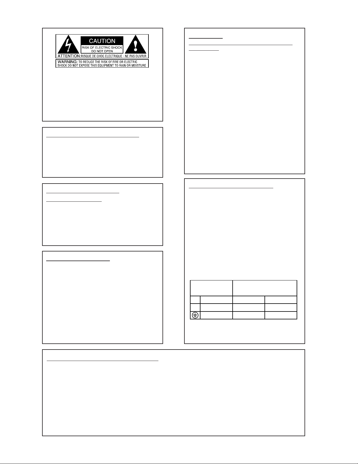
The symbols shown above are internationally accepted symbols that warn of
potential hazards with electrical products. The lightning flash with arrowpoint
in an equilateral triangle means that there are dangerous voltages present within the unit. The exclamation point in an equilateral triangle indicates that it is
necessary for the user to refer to the owner’s manual.
These symbols warn that there are no user serviceable parts inside the unit.
Do not open the unit. Do not attempt to service the unit yourself. Refer all
servicing to qualified personnel. Opening the chassis for any reason will void
the manufacturer’s warranty. Do not get the unit wet. If liquid is spilled on
the unit, shut it off immediately and take it to a dealer for service. Disconnect
the unit during storms to prevent damage.
ELECTROMAGNETIC
COMPATIBILITY
This unit conforms to the Product Specifications noted on the Declaration of
Conformity. Operation is subject to the following two conditions:
• this device may not cause harmful interference, and
• this device must accept any interference received, including
interference that may cause undesired operation. Operation of
this unit within significant electromagnetic fields should be
avoided.
• use only shielded interconnecting cables.
FCC COMPLIANCE
This equipment has been tested and found to comply with the limits for a Class
B digital device, pursuant to Part 15 of the FCC Rules. These limits are
designed to provide reasonable protection against harmful interference in a residential installation. This equipment generates, uses and can radiate radio frequency energy and, if not installed and used in accordance with the instructions, may cause harmful interference to radio communications. However, there
is no guarantee that interference will not occur in a particular installation. If
this equipment does cause harmful interference to radio or television reception,
which can be determined by turning the equipment off and on, the user is
encouraged to try to correct the interference by one or more of the following
measures:
• Reorient or relocate the receiving antenna
• Increase the separation between the equipment and receiver that may cause
undesired operation.
• Connect the equipment into an outlet on a circuit different from that to which
the receiver is connected
• Consult the dealer or an experienced radio/TV technician for help.
SAFETY INSTRUCTIONS
Notice For Customers If Your Unit Is Equipped With A Power Cord.
WARNING:THISAPPLIANCEMUSTBEEARTHED.
The cores in the mains lead are coloured in accordance with the following
code:
GREEN and YELLOW - Earth BLUE - Neutral BROWN - Live
As colours of the cores in the mains lead of this appliance may not correspond
with the coloured markings identifying the terminals in your plug, proceed as
follows:
• The core which is coloured green and yellow must be connected to the terminal in the plug marked with the letter E, or
with the earth symbol, or coloured green, or green and yellow.
• The core which is coloured blue must be connected to the terminal marked N or coloured black.
• The core which is coloured brown must be connected to the
terminal marked L or coloured red.
This equipment may require the use of a different line cord, attachment plug,
or both, depending on the available power source at installation. Connect this
equipment only to the power source indicated on the equipment rear panel. If
the attachment plug needs to be changed, refer servicing to qualified service
personnel who should refer to the table below. The green/yellow wire shall be
connected directly to the unit's chassis.
WARNING: If the ground is defeated, certain fault conditions in the unit or in
the system to which it is connected can result in full line voltage between
chassis and earth ground. Severe injury or death can then result if the chassis
and earth ground are touched simultaneously.
Line
Neutral
Earth Grnd.
CONDUCTOR
L
N
Brown
Blue
Green/Yel.
Black
WIRE COLOR
White
Green
DECLARATION OF CONFORMITY
Manufacturer’s Name: IVL Technologies Ltd.
per DigiTech specifications
Manufacturer’s Address: 6710 Bertram Place
Victoria, B.C.
Canada V8M 1Z6
declares that the products:
DigiTech VCS-1 Dynamics Processor
conform to the following product specifications:
EMC: EN 55022 (1987):
CISPR 22 (1993) Class B
EN 50082-1 (1992)
Supplementary Information:
The product herewith complies with the requirements of the Low Voltage Directive
73/23/EEC and the EMC Directive 89/336/EEC (1989) as amended by the CE
Marking Directive 93/68/EEC (1993).
IVL Technologies Ltd.
6710 Bertram Place
Victoria, B.C.
Canada V8M 1Z6
December 12, 1996
Peter George, Vice President of Engineering
European Contact: Your local DigiTech Sales and Service Office or
International Sales Office
3 Overlook Drive Unit #4
Amherst, New Hampshire 03031, USA Tel (603) 672-4244 Fax (603) 672 4246
Safety: EN 60065
IEC 65 (1993)
Amendment 1 (1987)
Amendment 2 (1989)
Amendment 3 (1992)
Page 3

Digitech VCS-1 Owner’s Manual
Table of Contents
Introduction ..........................................................................1
Connection Examples..........................................................2
Rear Panel............................................................................3
Wiring Scheme.....................................................................3
Line Input.............................................................................3
Level Switch........................................................................3
Sidechain Send & Return ....................................................3
Line Output..........................................................................4
Front Panel...........................................................................5
Output Control.....................................................................5
Clip LED ..............................................................................5
Tube Gain Control...............................................................5
VU Meter.............................................................................5
Trim Adjustment..................................................................6
Gate Threshold & Attenuation.............................................6
De-ess Control .....................................................................6
Peak Limiter.........................................................................7
Compressor Controls ...........................................................7
Meter Function Switch ........................................................8
Auto Switch .........................................................................8
Knee Switch.........................................................................8
Process Switch.....................................................................8
Stereo Link Switch ..............................................................8
Application Notes................................................................9
Specifications.....................................................................13
Signal Flow Diagram.........................................................15
DigiTech VCS-1 Owners Manual version 1.01 rev. 12/16/96
Page 4

Introduction
Thank you and congratulations on your purchase of the Digitech VCS-1. This product was developed to give you precise control over dynamics in digital recording, analog recording and live performance. The VCS-1 also has an adjustable-gain vacuum tube stage with analog VU metering and
LED peak indication.
The compression circuit is comprised of the latest solid state VCA components available. This
ensures that even under considerable compression, the VCS-1 will not contribute significant
amounts of noise or colouration to an audio signal. The attack and release timing is based on the
“True Logarithmic Compression” design that sounds most natural to human hearing and is an emulation of “vintage” compressor sound.
The vacuum tube amplification stage in the VCS-1 is a classic, high plate-voltage design utilizing a
pure class Atopology. A parallel-triode arrangement is employed, in addition to a fully-regulated
235V plate supply to maximize signal-to-noise performance and transient response. The premiumgrade 12AX7A vacuum tubes used in the VTP-1 are manufactured in Russia, and hand tested and
graded specifically for the VCS-1 by Audio Glassic in the USA.
Precision 1% metal-film resistors are used throughout the audio path to ensure performance stability
and low noise. In addition to precision resistors, all filter circuits utilize high quality plastic-film
capacitors to maintain spectral accuracy and minimize the long-term effects of component drift. To
ensure years of trouble-free operation, each VCS-1 must pass a rigorous set of performance tests and
a 24-hour burn-in period before it is shipped from the factory.
Features
• Fast, quiet industry standard VCA circuitry with “True Logarithmic Compression” timing
• Dual Class Avacuum tube stages
• Convenient single knob De-ess control
• Input, Output and Gain Reduction VU metering with LED peak indication
• Peak limiter circuit for transient peak protection
• Gate feature with variable attenuation level
• XLR and TRS 1/4” balanced inputs and outputs
• Sidechain loop for frequency-sensitive compression and gating
•••
1 •••
Page 5
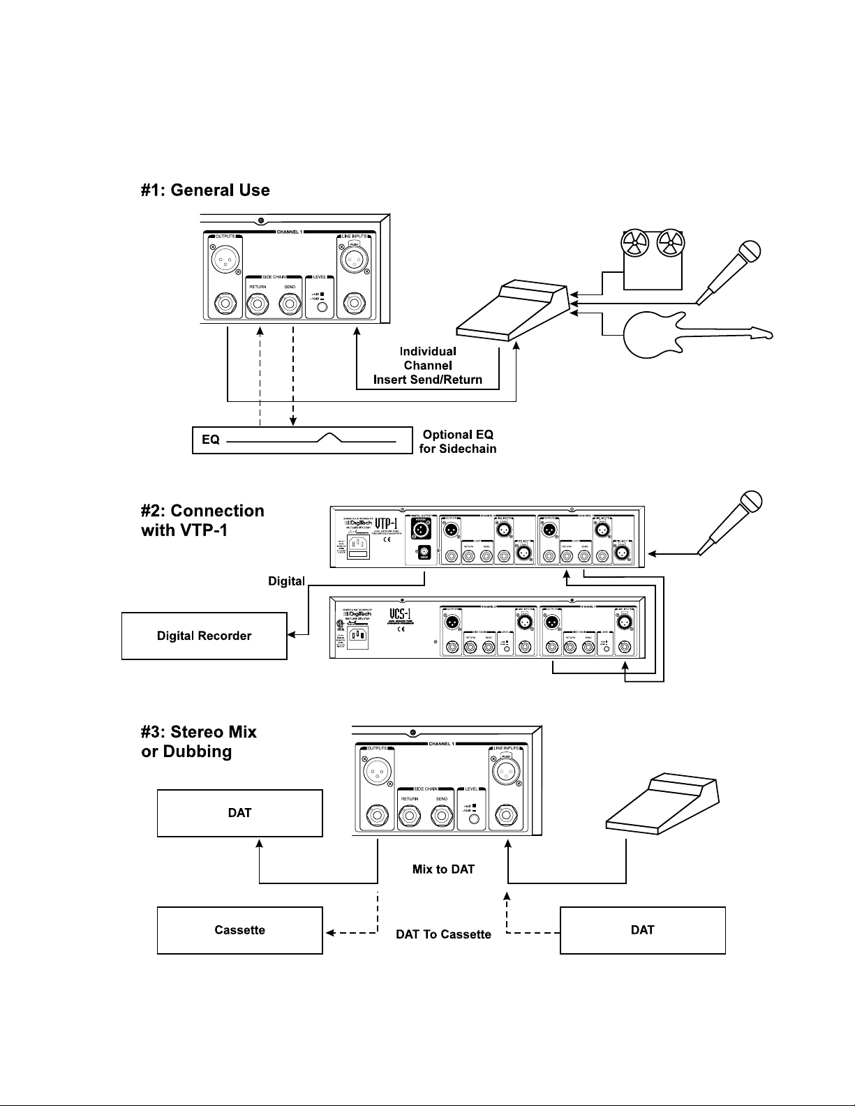
Connection Examples
The following diagrams show a few ways in which the VCS-1 can be used.
••• 2 •••
Page 6
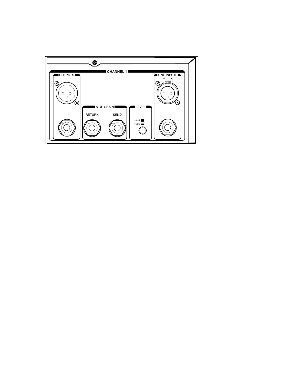
REAR PANEL
WIRING SCHEME
All of the XLR input and output connectors are pin 2 hot, meaning that pin 2 carries the positive
side of the balanced signal. Pin 3 is cold, carrying the negative polarity and pin 1 is the shield.
The 1/4” TRS jacks are wired so that when you use 3 conductor cables and balanced signals, the tip
is hot, the ring is cold and the sleeve is the shield. The 1/4” jacks can also be used with 2 conductor
unbalanced cables. In this case, the tip is hot and the ring and sleeve are grounded.
LINE INPUT
The XLR connector for the line input is electronically balanced and will accept +4 dBu or -10 dBV
signals. The 1/4” phone connector is also a balanced input using TRS (Tip Ring Sleeve) connectors.
TRS jacks require a cable with stereo phone jacks to be used if balancing is desired. The 1/4” TRS
inputs can also be used with an unbalanced source using a standard two conductor cable. Plugging a
1/4” connector into the phone jack input will override signal coming into the XLR input.
LEVEL SWITCH
This switch sets the nominal operating level for the line input only. When the switch is in the -10
dBV position a small amount of gain is added to the input signal to match the internal level of the
VCS-1. Consult your manual on any device connected here if you are unsure of which setting is
best.
SIDECHAIN SEND AND RETURN
These connectors allow you to insert an external processor or audio signal into the detector signal
path which is known as a “Sidechain”. Sidechain processing is used to accomplish frequency-sensitive compression, keyed gating and ducking. The Sidechain Send output level is +4 dBu and the
connector is 1/4” TRS impedance balanced. The Sidechain Return is +4 dBu unbalanced.
••• 3 •••
Page 7

LINE OUTPUT
This output is servo-balanced producing +4 nominal level to XLR and 1/4” TRS connectors.
Unbalanced cables may be used also.
•••
4 •••
Page 8

••• 5 •••
Front Panel
OUTPUT CONTROL
This center-detented knob controls the output level. The center detent indicates unity gain. Provided,
the Tube Gain control is in the center detent position as well. The output level can be adjusted to
provide make-up gain when the compressor is active, or reduce the output level fed to a device that
will only accept -10 dBV signals. You would also reduce the output level to retain unity levels when
increasing the vacuum tube saturation with the TUBE GAIN control. In either case, you should
switch back and forth between Bypass and Active to ensure level unity.
Note: If the Stereo Link 1>2 switch is In, the Output controls for Channel 1 and 2 remain
independent. The Tube Gain control for Channel 1 controls Tube Gain for both channels.
CLIP LED
The Clip LED is a fast-acting indicator to warn you of quick transient peaks that can cause audible
output distortion. The Clip LED will light when the signal is 3 dB below the onset of clipping.
Critical points in the audio path are monitored so that clipping cannot occur in any one stage.
TUBE GAIN CONTROL
This control determines the amount of gain the tube amplifier will apply to the input signal. Unity
gain for a signal passing through the VCS-1 is achieved when this and the OUTPUT control are at
the center detent position. As you increase the TUBE GAIN you will increase the amount of tube
saturation that, in moderate amounts, enhances pleasant even order harmonics but in greater
amounts, can cause audible distortion. If you have the TUBE GAIN control set to a level causing
tube saturation, you should lower the OUTPUT level so you don’t overdrive the outputs.
VU METER
The VU Meter can be used to indicate input level, output level and the amount of gain reduction.
The following shows how each display mode is selected.
Page 9

••• 6 •••
• Line input level: PROCESS switch set to Bypass, METER switched to Output
• Line output level: PROCESS switch set to Active, METER switch set to Output
• Compressor gain reduction: PROCESS switch set to Active or Bypass, METER switch set to G.R.
• “0 VU” is calibrated to +4 dBu for the input and output VU modes and 0 dB of gain reduction in
G.R. mode.
VU meters are calibrated in Volume Units to give an average signal level reading. The key term here
is “average” because VU meters show the average difference between the peaks and valleys in the
level of the program material. While VU meters generally show an accurate level for a synthesizer
pad sound where the dynamic differences are slight, they will let brief peaks through that don’t register on the needle such as those from an energetic Bass guitar track. See the Application Notes section at the end of this manual for more information on VU metering.
TRIM
This trimpot allows adjustment of the 0 VU setting for gain reduction display only. This is precisely
set at the factory however it may need re-calibration from time to time. To adjust, set the Meter
mode to show gain reduction and use a jeweler’s flathead screwdriver to align the needle with the 0
VU mark.
GATE THRESHOLD
This control determines the level at which the noise gate closes. Turning the control clockwise raises
the threshold at which the gate will open. For example, if you have set the threshold to -20 dBu,
only signals louder than -20 dBu open the gate and thus, be audible. The gate is fully open or “off”
in the furthest left (counter-clockwise) position. The indicator LED shows that the gate is closed.
GATE ATTENUATION
When the gate closes, this control sets how much level reduction is desired. The reasoning behind
this is that you don’t always want the gate to close fully. A slight attenuation will reduce, but not
eliminate crowd noises for instance. Less gate attenuation will also make the opening time as fast as
possible because although the gate is extremely fast, it will always open more quickly when starting
from an intermediate level. If the attenuation is set to 0 attenuation the gate is inactive regardless of
the threshold setting.
DE-ESS ATTENUATION
This knob is used to adjust the amount of gain reduction applied to sibilant vocal frequencies that
result from “ess”, “tee”, “ch” and “dee” sounds. When the De-ess control is turned clockwise, a program peak above the 4.5 kHz knee frequency will cause the de-esser to quickly “duck” the audio
down and back up again. Because the gain reduction is broadband (all frequencies) this is optimized
for vocal de-essing only and it is not suitable for full program material. The LED shows when sibilants are being attenuated.
Page 10

••• 7 •••
PEAK LIMITER THRESHOLD
The Peak Limiter puts an instantaneous “ceiling” on the transient peak levels of your audio material
without affecting dynamics below the threshold. This feature is essential for digital recording and
speaker protection for live sound. In the furthest clockwise position, the limiter is off. Turning the
control counter-clockwise engages the peak limiter. The LED shows when peak limiting occurs and
the VU meter (in the G.R. switch position) will show the amount of attenuation.
COMPRESSOR THRESHOLD
The compressor threshold control is used to set the minimum level at which you want gain reduction
to occur. Turning this control counter-clockwise from the rightmost +20 dBu position brings the
threshold lower so that more of the program material is compressed. The Green (-) LED shows that
the audio signal is below the threshold and is not being compressed. The Red (+) LED shows that
audio has exceeded the threshold and is being compressed.
Note: The legend around this control are calibrated for the Hard Knee setting. When you
switch to Soft Knee, you should turn this control 10 dB in the clockwise direction to achieve
equivalent gain reduction due to the increased gain of the soft knee detector circuit.
COMPRESSOR RATIO
This control varies the amount of “squeeze” you need for the audio material that exceeds your
threshold setting. Turning the control clockwise from the 1:1 (off) position increases the ratio from
gentle compression (2:1 to 8:1) to hard limiting (>8:1). Compression is expressed as a ratio to show
that, for a specified increase in input level, there will be 1dB increase in output. For example, a ratio
of 10:1 means that for a 10 dB increase in input level, the output will only increase by 1 dB.
ATTACK TIME
The Attack Time control allows you to tailor how fast the compressor acts on audio exceeding the
threshold. Slowing the attack time allows a little of the input transient from a drum or guitar to slip
through before compression sets in. This can preserve punch while keeping levels under control.
Faster attack times tend to cause a more obvious compression effect.
RELEASE TIME
Release Time is the time it takes for the compressed signal to return to its original level once the
input signal is no longer above threshold. The VCS-1 uses a true logarithmic timing circuit called
“TLC” (True Logarithmic Compression) that more closely matches the response curve of human
hearing and results in very natural-sounding dynamic control. This timing curve evokes the “classic”
sound of vintage compressors so popular today. The TLC timing is most transparent at longer
release times but will produce a pleasing effect at short settings as well.
Page 11

••• 8 •••
METER FUNCTION
This switch allows you to toggle the VU meter display between monitoring input level, output level
or gain reduction. In the G.R. (gain reduction) setting, the meter needle will center on the 0VU portion of the legend and swing to the left indicating how much attenuation is occurring due to the
compressor or peak limiter. When this switch is in the Output position and the channel is active
(Process switch is in the Active position), the VU meter will show output level. Switching the
Process switch to Bypass while in the Output position causes the VU meter to display input level.
Further information on setting levels with the VU meters is available in the Applications section.
AUTO
The Auto switch enables a circuit that overrides the manual Attack and Release controls. When the
Auto switch is “In”, the attack and release timing will depend on the changing dynamics of the input
signal. Auto can be used to make setup faster or to emulate the sound of “classic” compressors. The
Auto circuit can also be used to reduce fast release time distortion on signals with sustained low frequency content such as bass guitar.
KNEE
The Knee switch allows you to select a “Hard” or “Soft” transition into compression. As the audio
signal approaches the threshold, the Soft Knee setting will initiate a more gentle transition to compression from just below the threshold. This results in more natural sound even with higher ratios
and attack times. The Hard knee is more useful for obvious compression effects and is particularly
useful for peak limiting.
Note: The Threshold control is calibrated for Hard Knee. When using Soft Knee you will need
to raise the threshold by 10 dB to achieve similar compression.
PROCESS
This switch allows you to bypass each channel individually. When in the Bypass position, the
Output and Tube Gain controls are bypassed and all dynamics circuitry is removed from the audio
path. In the Active position, all dynamic circuitry and level controls are active. The Bypass function
is essential for comparing the original audio with any changes you have made. It is also important
for matching input and output levels if you have adjusted either the Tube Gain or Output controls.
STEREO LINK 1>2
The Stereo Link circuit assesses relative power of the left and right channels of stereo input material
to preserve proper left/right balance under compression. When this switch is in the In position, the
dynamic controls for Channel 1 become the master for both channels. Because Channel 1 is the
master, the LEDs and controls in Channel 2 will become inactive.
With Stereo Link engaged:
• Tube Gain from Channel 1 affects both channels
• Output controls are independent
• Bypass controls are independent
Page 12

APPLICATION NOTES
Compression
Vocals:
Unless the vocalist you are recording has exceptional microphone control, some compression is
always welcome on a vocal track. Agenerally accepted practice, is to use a light compression ratio
of 2:1 or so when first recording the vocal to tape then, later to increase the ratio amount depending
on the density of the mix. Aside effect of vocal compression is that it raises the level of lip smacks,
breathing and grunts which may be gated. Another side effect of compression is the increased level
of sibilance. You may need the De-esser function to compensate.
Drums:
Compression on drums is very effective in increasing punch without adding level or EQ. Bass drum
and snare should be compressed separately but a stereo mix of the rack toms can be compressed
together. Experiment with slow manual attack time settings and an 8:1 ratio. These settings will let
brief percussive transients through, while reducing low frequency flap. Using the Soft knee setting
will accomplish a similar effect where the beginning “tick” of a drum is passed before compression
occurs.
Bass
Bass guitar is a particularly dynamic instrument. This is especially noticeable when the Bass is
played with pop/slap technique. Without compression you can end up with peaks that distort and
low level notes that disappear in the mix. Switch in the Auto setting and start with a ratio of 4:1.
Auto is best for reducing release time chattering on sustained bass notes but you can switch to manual as long as the release time is set fairly long. With higher ratios you can increase the apparent
sustain of bass notes making a nice “bed” for the rest of the mix to sit on. The sound of a pick on
roundwound strings can be emphasized by using slower attack times in manual timing mode.
Mixdown
Assuming your individual tracks were lightly or not compressed to tape, you can consider adding a
bit of overall “mastering” compression to your mixes. Anote of caution though: good mastering is
done by professionals with years of experience. Be careful not to overdo it. Compression can, however help greatly when you are making cassette dubs from DAT. Cassettes cannot handle dynamics
like DAT so it’s a good idea to compress when dubbing. Agood setting to start with is with Auto on
and a ratio of 2:1. The Auto setting is program-dependent and it works well with mixed program
material.
Peak Limiting
Peak limiting is an important asset during live-to-digital recording. Input levels set at the beginning
of a recording date can be exceeded as the players perform with more enthusiasm than during the
sound check. The peak limiter in the VCS-1 can be used to reduce the number of transient peaks
causing digital distortion with no effect on dynamics below the threshold.
•••
9 •••
Page 13

Set the Threshold control to the maximum level you want to send to your recorder which, for most
digital recorders, is 0 VU. Because 0 VU is referenced differently from one manufacturer to another,
start by setting the Limiter Threshold to +10 dBu. For additional protection, you can engage the
compressor at 2:1 ratio with a threshold just below the Limiter setting.
Gating
One of the most basic uses of a gate, is to reduce the noise floor raised by compression. Other applications include removing unwanted low level sounds from instrument and vocal tracks as well as
reducing ambient sound level in a vocal or announcement mic. More creative use of a gate involves
the use of a sidechain processor. This is discussed in the Sidechain section below.
De-essing
The De-esser in the VCS-1 is optimized for vocal applications where gain reduction is applied on
the sibilant parts of speech or singing. Vocal tracks that require de-essing are usually the result of
large amounts of compression and/or the addition of high-mid frequency EQ. These techniques
increase the intelligibility of the vocal but they also increase the amount of harsh high frequencies.
You should start by setting the de-ess attenuation to 6dB and evaluate the full length of the program
material if you can. If you have a vocal track where the sibilant range is higher than the VCS-1’s 4.5
kHz, you can connect an equalizer into the Sidechain. In this way you can experiment with the optimum frequency by boosting individual frequencies until you find the correct one.
Because sibilance and vowels generally do not occur together, the De-esser is a broadband-type that
attenuates all frequencies simultaneously.
Sidechain
The most common application of the sidechain is to insert an equalizer with certain frequencies
boosted or cut causing frequency-sensitive compression. An EQ in the sidechain does not affect the
frequency balance of the audio you intend to compress, it only affects what specific frequency causes the compressor to activate. Boosting frequencies above 4 kHz produces the classic “de-essing”
effect. There is a convenient circuit in the VCS-1 that does this for you but additional sidechain EQ
usages include:
• cutting of low frequencies to make the compressor less sensitive to bass drum in an overall mix,
for example.
• boosting high frequencies to make the compressor more sensitive to cymbals or the high-mid blare
of guitar amps.
• To vary the gate’s sensitivity-bias to certain frequencies.
Sidechain can also be used to adjust the response of the gate in the VCS-1. A common usage is to
feed a bass drum track into the sidechain return while a send from a bass guitar track is connected to
the VCS-1’s line input. The line output of the VCS-1 is fed to another mixer channel at a slightly
higher level so that when the gate opens in time with the bass drum, there is a little dynamic boost
in the bass track.
•••
10 •••
Page 14

Creative effects are possible with sidechain gating as well. Sustained sounds from a synthesizer can
be layered onto real drums without MIDI using the technique described in the preceding paragraph.
Run a synth tone such as noise, or a pure sine wave into the line input of the VCS-1 and out to a
mixer channel. Into the sidechain return, run a signal from a snare or bass drum track. This “trigger”
track must be well isolated to work properly so use the other channel of the VCS-1 to gate any
unwanted sounds.
“Ducking” or “keyed attenuation” are useful combination effects of a compressor and sidechain.
This is used often in hotels where the level of background music is reduced when an announcer
speaks into a microphone. It is also used in the studio to reduce the level of sustained effects such as
reverb or echo when the instrument is played and raise the effect level when the instrument stops
sounding. This serves to accentuate the effect but not wash out the instrument. The audio signal you
want to duck (such as the background music or reverb) is connected to the VCS-1 Line input and the
audio signal you want to override the input signal is connected to the Sidechain Return. The amount
of attenuation is controlled by the Ratio and Threshold controls, but varying the amount of level
received from the Sidechain Return works also.
Understanding VU Meter and Clip LED Readings
The functions of the VU Meter and Clip LED combine to give an excellent indication of average
and peak levels. The ballistics of the VU Meter are optimized to show the subjective loudness of the
audio material. Quick peaks have little effect on meter movement because to our ears, constant moderate levels will appear subjectively louder than lower levels with higher transient peaks.
Because the VCS-1 is unity gain device, the VU meter is mostly used in gain reduction mode to
show the amount of compression rather than input or output levels. If you plan to use the VU meter
to monitor input or output levels, it must be understood that actual levels generally exceed what is
shown on the meter. This is especially true with transient-rich percussive tracks. The meter level
may show -20 VU but the actual level may be +10 dBu or higher.
Should you need to add gain to a weak input signal or increase level lost to compression, you may
need to use the VU meters to ensure you are not adding too much. You can increase the Tube Gain
or Output level controls to increase meter movement until the Clip LED lights. The Clip LED lights
at +18 dBu, 3 dB before the VCS-1 circuitry clips. While this is generally the amount of headroom
professional gear has, it may be excessive for semi-pro or amateur gear. In this case, you should
check that the input level meter in the next device in the chain is not reporting a clip.
••• 11 •••
Page 15

••• 12 •••
Page 16

VCS-1 SPECIFICATIONS
System Performance
Signal-to-Noise Ratio: > 102 dB, Aweighted
Total Harmonic Distortion + Noise: < 0.1% typical, user-variable
Frequency Response: +0, -1 dB from <10 Hz to 35 kHz
+0, -3 dB from <10 Hz to 70 kHz
Inputs
Connectors: Female XLR and 1/4” TRS
(XLR pin 2 and TRS tip hot)
Input Impedance: 20 kΩ
Maximum Input Level: +21 dBu
Outputs
Connectors: Male XLR and 1/4” TRS
(XLR pin 2 and TRS tip hot)
Output Impedance: <100 Ω
Nominal Output Level: balanced or unbalanced: +4 dBu
Maximum Output Level: balanced or unbalanced: +21 dBu
Side Chain Send
Connector: 1/4” TRS (tip hot)
Type: Impedance balanced
Impedance: 1 kΩ
Max Output Level: +21 dBu
Side Chain Return
Connector: 1/4” TS
Type: Unbalanced
Impedance: >20 kΩ
Max Input Level: +21 dBu
Compressor
Threshold Range: -40 to +20 dBu
Ratio: 1:1 to ×:1
Threshold Characteristic: Soft or Hard knee
Attack/Release Modes: Manual or Auto
Manual Attack Range: 0.1 to 200 ms
Manual Release Range: 50 ms to 3 seconds
Auto Attack/Release Time: Variable, program dependent
•••
13 •••
Page 17

Peak Limiter
Threshold Range: -8 to +24 dBu (off)
Attack Time: Typically <10 ms
Release Time: Program dependent
Gate:
Threshold Range: -60 to +20 dBu
Maximum Attenuation variable from 0 to 60 dB
Attack Time: Typically <10 ms from maximum attenuation
Release Time: Program-dependent
De-esser
Attenuation Range: 0 (Off) to 28 dB
Ratio: ×:1
Detection Filter: 3 pole highpass, -3 dB @ 4.5 kHz
Vacuum Tube Circuit
Type: Class A, high-voltage parallel-triode design
Tube Complement Single 12AX7Aper channel
Saturation: User-variable
Power Requirements:
Operating Voltage 120 V AC, 50/60 Hz
or as specified on rear panel (International)
Power Consumption 30 Watts
Fuse: 315 mA, slo-blo
Mains Connection IEC receptacle
General
Lamp bulb: Manufacturer: Shogyo P/N: 7152
5 VDC @ 115 mA0.15 Candle Power
Dimensions: 48 cm W x 8.9 cm H x 14.6 cm D
(19” W x 3.5” H x 5.75” D)
Weight: 3.6 kg (8 lbs.)
Specifications subject to change without notice
•••
14 •••
Page 18

••• 15 •••
DIGITECH VCS-1 SIGNAL FLOW DIAGRAM (One Channel Only)
Page 19

Printed in the USA
18-2202-A
 Loading...