

Page 1
Valve FX
Guitar Preamp/
Signal Processor
A Harman International Company
INPUT OUTPUT PRESENCE
GUITAR PREAMP / SIGNAL PROCESSOR
DSP Clip
-18
-12
-6
0
Bypass
Program Number
FX
Owner's Manual
S-DISC
™
PROCESSING
Page 2

1
Table Of Contents.............................................................1
Introduction .......................................................................3
Safety Precautions ............................................................3
Lithium Battery Warning....................................................4
Warranty............................................................................4
SECTION 1 - STARTUP Supplying Power...............................................................6
Front Panel Controls .........................................................6
Input............................................................................6
Headphone Output.....................................................6
Main Output Level ......................................................6
Presence Control........................................................6
Display Window..........................................................7
Cursor Keys................................................................7
Effects Access............................................................8
Global Buttons............................................................8
Data Wheel .................................................................8
Power Switch ..............................................................8
Rear Panel Connections ...................................................8
AC Line Input..............................................................8
Foot Controller ............................................................8
MIDI In ........................................................................8
MIDI Out .....................................................................8
Outputs.......................................................................9
Input............................................................................9
MIDI and Audio Setups.....................................................9
SECTION 2 - BASIC OPERATIONS Main Operating Mode.......................................................11
Parameter Architecture.....................................................11
Accessing Factory Programs ...........................................12
SECTION 3 - PROGRAMMING Using the Function Keys...................................................13
More Special Characters ..................................................13
The Effects Access Keys..................................................14
About The I/O Module.......................................................14
Modifying Factory Programs.............................................14
Basic Program Creation....................................................16
Selecting an Algorithm......................................................16
Storing and Naming Programs .........................................17
SECTION 4 - EFFECTS AND PARAMETERS About The Effects Library .................................................20
Analog Effects...................................................................20
Compressor................................................................20
Distortion.....................................................................20
Equalizers .........................................................................22
4-band PEQ / 10-band GEQ ......................................22
Cabinet Emulator........................................................23
Reverbs.............................................................................24
BigVerb / MFX Reverb................................................24
Gated Reverb .............................................................28
Delays / Sampler...............................................................30
Delays.........................................................................30
Sampler ......................................................................32
Pitch Shifters .....................................................................34
Pitch Shifters...............................................................34
Detuners .....................................................................35
Whammy™ .................................................................35
Arpeggiators...............................................................36
Table of Contents
Valve FX Owner’s Manual
Page 3

2
Modulation Effects ............................................................37
Choruses ....................................................................37
Flangers......................................................................38
Phasers.......................................................................39
Tremolos.....................................................................39
Auto Panners ..............................................................39
Mixers................................................................................40
More ..................................................................................41
Noise Gates................................................................41
DSP Level ...................................................................42
Wahs...........................................................................42
Duckers ......................................................................42
Phase Inverter ............................................................43
SECTION 5 - THE UTILITY MENU Utility Menu .......................................................................44
MIDI Sub-Menu.................................................................44
MIDI Channel ....................................................................44
Send Prg (Program Change)............................................45
Prg Send Map...................................................................45
Prg Rcv Map .....................................................................47
Continuous Controller Links..............................................48
Display CC’s .....................................................................52
Bulk Dump ........................................................................52
MIDI Program Dump.........................................................53
MIDI Merging ....................................................................54
Programming The Footswitch ...........................................54
Patch Assignment.............................................................55
Program, Bank Up/Down ..................................................56
Toggle CC.........................................................................56
Int Ped = CC.....................................................................56
List Up / Down ..................................................................57
Prg List Asssign ................................................................57
Continuous Control Pedal .................................................58
Assign CC Number...........................................................58
CC Transmit Channel........................................................59
Pedal Calibration...............................................................60
LED Assignment ...............................................................62
Tuning From The Front Panel ...........................................62
Tuning From The Foot Controller ......................................63
Changing The Tuning Reference .....................................63
Adjusting The LCD Contrast.............................................64
Output Mode.....................................................................64
Cabinet Emulation.............................................................65
Sales Banner.....................................................................65
Reinitializing The Valve FX................................................66
SECTION 6 - APPENDIX Specifications....................................................................68
Factory Algorithm Diagrams .............................................69
Block Diagram ..................................................................78
Factory Program List.........................................................79
MIDI Implementation Chart...............................................80
Table of Contents
Valve FX Owner’s Manual
Page 4
3
INTRODUCTION Congratulations, and thank you for your purchase of the DigiTech
Valve FX Guitar Preamp / Signal Processor. The Valve FX combines
the world’s most powerful digital signal processor, the S-DISC™ with
real tube distortion or one of our three most popular solid state distortion types. These digital multi-effects are second to none, and when
joined with the warmth and clarity of one of the best analog preamps
on the market, the results are amazing. Special features of the Valve
FX include:
• Full bandwidth effects (20-20kHz)
• 24-bit signal path, 48-bit internal data transmission
• Stereo processing
• Instant Module and Parameter access
• The Control One remote foot controller (optional)
• Programmable cabinet emulation for running direct to a mixing
console (great for both studio and live applications)
• Front panel Presence control and headphone output
• Full MIDI implementation
• Built-in MIDI merging (MIDI output can act as a standard out or
as a merged out)
• MIDI Transmit and Receive mapping
• All effects and parameters are available for MIDI continuous
control with up to 10 CC links available per program
For the first time, all of your effects needs can be filled by a single unit
with 16-bit digital clarity. This owner’s manual is your key to understanding the powerful world of the Valve FX. Read it carefully. After
you’ve had time to familiarize yourself with the unit, try experimenting
with unusual effects settings. You may achieve some interesting
results.
SAFETY PRECAUTIONS
The symbols shown above are internationally accepted symbols that
warn of potential hazards with electrical products. The lightning flash
with arrowpoint in an equilateral triangle means that there are dangerous voltages present within the unit. The exclamation point in an equilateral triangle indicates that it is necessary for the user to refer to the
owner’s manual.
Introduction and Safety Precautions
Valve FX Owner’s Manual
CAUTION
RISK OF ELECTRIC SHOCK
DO NOT OPEN
ATTENTION:
WARNING:
SHOCK DO NOT EXPOSE THIS EQUIPMENT TO RAIN OR MOISTURE
RISQUE DE CHOC ELECTRIQUE - NE PAS OUVRIR
TO REDUCE THE RISK OF FIRE OR ELECTRIC
Page 5

4
These symbols warn that there are no user serviceable parts inside
the unit. Do not open the unit. Do not attempt to service the unit
yourself. Refer all servicing to qualified personnel. Opening the
chassis for any reason will void the manufacturer’s warranty. Do not
get the unit wet. If liquid is spilled on the unit, shut it off immediately
and take it to a dealer for service. Disconnect the equipment during
storms to prevent damage.
U.K. ONLY - A moulded mains plug that has been cut off from the
cord is unsafe. Discard the mains plug at a suitable disposal facility.
NEVER UNDER ANY CIRCUMSTANCES SHOULD YOU INSERT A
DAMAGED OR CUT MAINS PLUG INTO A 13 AMP POWER SOCKET.
Do not use the mains plug without the fuse cover in place.
Replacement fuse covers can be obtained from your local retailer.
Replacement fuses are 13 amps and MUST be ASTA approved to
BS1362.
LITHIUM BATTERY WARNING CAUTION! This product contains a lithium battery. There is danger
of explosion if battery is incorrectly replaced. Replace only with an
Eveready CR 2032 or equivalent. Make sure the battery is installed
with the correct polarity. Discard used batteries according to manufacturer’s instructions.
ADVARSEL! Lithiumbatteri - Eksplosjonsfare. Ved utskifting benyttes
kun batteri som anbefalt av apparatfabrikanten. Brukt batteri
returneres apparatleverandøren.
ADVARSEL! Lithiumbatteri - Eksplosionsfare ved fejlagtig håndtering.
Udskiftning må kun ske med batteri av samme fabrikat og type. Levér
det brugte batteri tilbage til leverandøren.
VAROITUS! Paristo voi räjähtää, jos se on virheellisesti asennettu.
Vaihda paristo ainoastaan laitevalmistajan suosittelemaan tyyppin.
Hävitä käytetty paristo valmistajan ohjeiden mukaisesti.
VARNING! Explosionsfara vid felaktigt batteribyte. Använd samma
batterityp eller en ekvivalent typ som rekommenderas av apparattillverkaren. Kassera använt batteri enligt fabrikantens instruktion.
WARRANTY 1. The warranty registration card must be mailed within ten days after
purchase date to validate this warranty.
2. DigiTech warrants this product, when used solely within the U.S., to
be free from defects in materials and workmanship under normal
use and service.
Warnings and Warranty
Valve FX Owner’s Manual
Page 6

5
3. DigiTech liability under this warranty is limited to repairing or
replacing defective materials that show evidence of defect, provided the product is returned to DigiTech WITH RETURN AUTHORIZATION, where all parts and labor will be covered up to a period of
one year. A Return Authorization number may be obtained from
DigiTech by telephone. The company shall not be liable for any
consequential damage as a result of the product’s use in any circuit
or assembly.
4. Proof-of-purchase is considered to be the burden of the consumer.
5. DigiTech reserves the right to make changes in design or make
additions to or improvements upon this product without incurring
any obligation to install the same on products previously manufactured.
6. The foregoing is in lieu of all other warranties, expressed or implied,
and DigiTech neither assumes nor authorizes any person to
assume for it any obligation or liability in connection with the sale of
this product. In no event shall DigiTech or its dealers be liable for
special or consequential damages or from any delay in the performance of this warranty due to causes beyond their control.
DigiTech™, S-DISC™, Whammy™ and Silencer™ are registered
trademarks of DOD Electronics Corporation.
The information contained in this manual is subject to change at any
time without notification. Some information contained in this manual
may also be inaccurate due to undocumented changes in the product
or operating system since this version of the manual was completed.
The information contained in this version of the owner’s manual supersedes all previous versions.
Warnings and Warranty
Valve FX Owner’s Manual
Page 7
6
SECTION 1 - STARTUP
SUPPLYING POWER Line Conditioning - The Valve FX, like any piece of computer hard-
ware, is sensitive to voltage drops, spikes, and surges. Interference
such as lightning or power “brownouts” can seriously, and in extreme
cases, permanently damage the circuitry inside the unit. Here are
some ways to avoid this type of damage:
• Spike/Surge Suppressors - This is an inexpensive solution to all
but the severest of AC line conditions. Surge protected power
strips usually cost only slightly more than unprotected strips,
making them a worthy investment for protection of all your valuable gear.
• AC Line Conditioners - This is the best way to go for total protection from improper line voltages, albeit the more expensive
way. Line conditioners constantly monitor for excessively high
or low voltages and adjust accordingly, thus delivering consistent power levels.
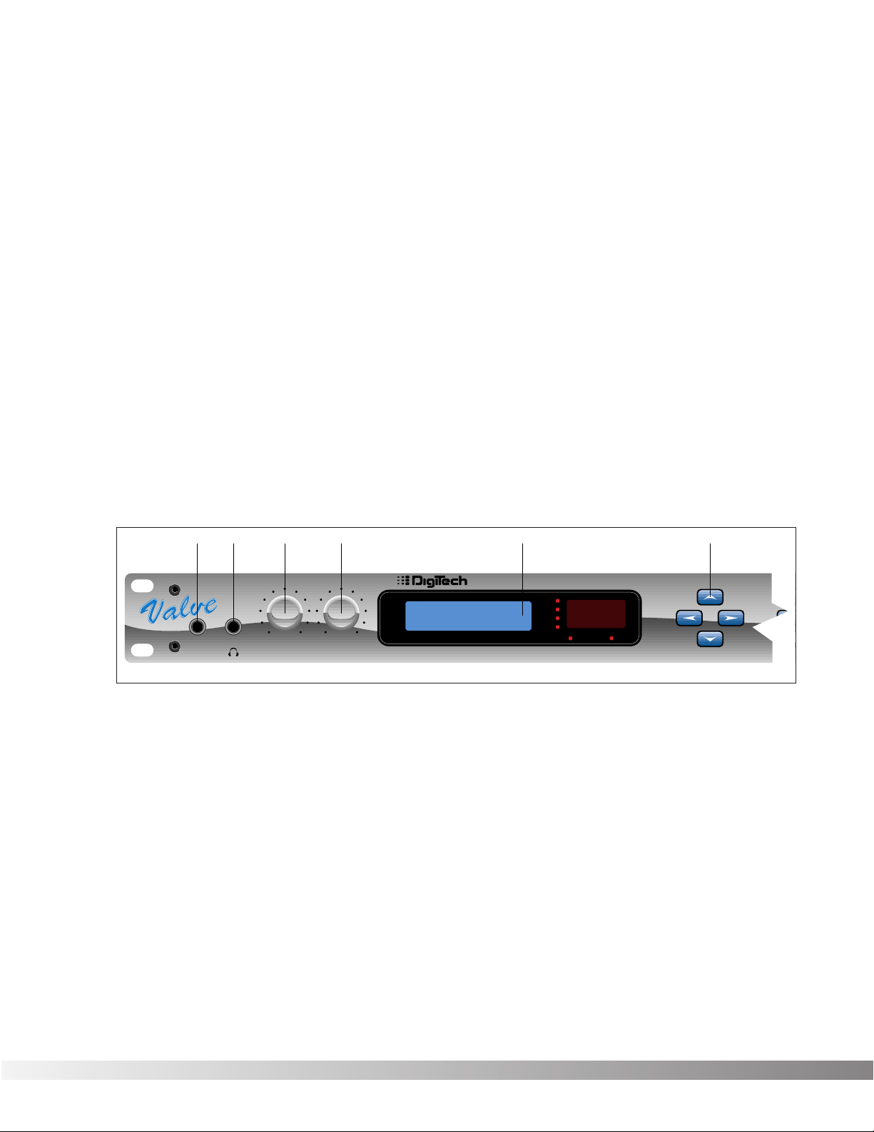
FRONT PANEL CONTROLS The front panel controls and functions of the Valve FX are as follows
(refer to diagram):
1) Input - Plug your instrument in here. The front panel input is a 1/4”
unbalanced tip-sleeve connector. When using the front panel
input, the rear panel input is automatically disengaged.
2) Headphone Output - 1/4” stereo plug for headphones (do not use
a mono 1/4” plug). The headphone level is controlled by the main
output level knob.
3) Main Output Level - Controls the overall output level of the Valve
FX. Also controls the overall level of the headphones.
4) Presence Control - Controls the overall brightness of the output
signal. Turn it up for bright, sparkling high-end response or down
for a dark, mellow tone. Frequency center for this control is 10 kHz.
Section 1 - Startup
Valve FX Owner’s Manual
23 4156
FX
Program Number
0
-6
-12
-18
DSP Clip
Bypass
CURSORINPUT OUTPUT PRESENCE GUITAR PREAMP / SIGNAL PROCESSOR
Reverb
Pitch
Mod
1
Page 8
7
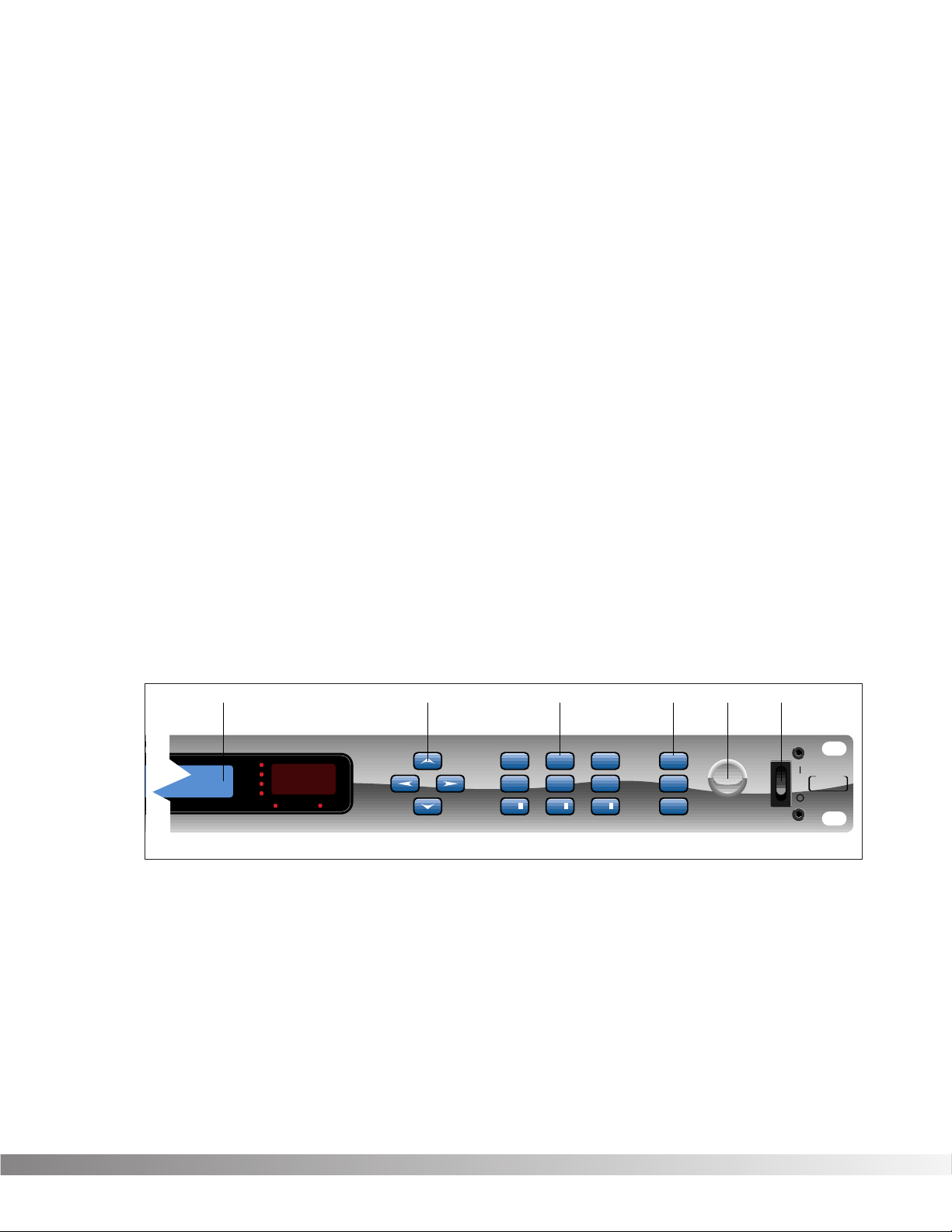
5) Display Window - The display window shows all current operating
and programming information and is comprised of several parts:
the LCD display, the input level meter, the Program number indicator, and the Bypass and DSP Clip indicator LEDs. The LCD display
shows all Program names, Parameters and Parameter values, and
is the communication interface between you and the Valve FX. The
input level meter monitors the level of the signal before it enters the
analog to digital converter. In the Program number indicator window you will find the currently selected Program number. This
changes as you scroll through the available Programs. The functions of the Input Level Meter, Bypass and DSP Clip indicator LEDs
are as follows:
• Input Level Meter - Displays the strength of the incoming signal
in 6 dB steps before it enters the analog to digital converter.
• Bypass Indicator - Indicates (when lit) that all effects have been
bypassed using either the Bypass button or the optional Control
One foot controller. To exit bypass mode, simply press the
Bypass button on the front panel or on the foot controller.
• DSP Clip - Indicates digital information overflow in the processor. When lit, distortion may be heard in the output signal. The
guideline for this indicator is let your ears be the judge. If this
indicator lights occasionally and no audible distortion is present,
it can be ignored. If distortion is audible in the output signal, the
EQ levels or perhaps one of the internal digital effects levels of
the Program must be turned down to eliminate the problem.
6) Cursor Keys - The Cursor keys perform several different functions
depending on your location in the menu. When the Program title is
displayed, the <UP> and <DOWN> Cursor keys scroll through
Programs, while the <LEFT> and <RIGHT> Cursor keys move
through Parameters. The Algorithm selection screen is one screen
to the right of the Program title screen. On this screen, the <UP>
and <DOWN> Cursor keys select the Algorithm you want to use
with the Program. On any other screen, the <UP> and <DOWN>
keys increment or decrement through Parameter values.
Section 1 - Startup
Valve FX Owner’s Manual
/ SIGNAL PROCESSOR
5678910
Program Number
0
-6
-12
-18
DSP Clip
Bypass
Reverb
Pitch
Mod
EFFECTS ACCESSCURSOR DATA
Delay
Sample
Mix
Chorus
More
EQ
321
Name
Midi/Util
Bypass
S-DISC
PROCESSING
™
Page 9
8
7) Effects Access - This group of buttons allows you to jump directly
to the first Parameter of Modules in the currently selected
Algorithm. The buttons in this group are: <EXIT>, <CMP/DIST>,
<EQ>, <REVERB>, <DLY/SMP>, <PITCH>, <MOD>, <MIX>, and
<MORE>. Also included in this section and sharing buttons with
the <MOD>, <MIX>, and <MORE> buttons are the Function keys
(indicated by ¡, ™,and £) which act as menu selection keys in the
Utility menus. The <EXIT> key is used for backing out of multi-level
submenus one level at a time or returning to the title screen
(depending where you currently are in the menus).
8) Global Buttons - Buttons in this group are: <STORE>, <UTILITY>,
and <BYPASS>. These buttons perform global functions, including
those required for storing Programs, Utility functions such as LCD
contrast and footswitch setup, MIDI setups (including transmit and
receive maps), and global bypass.
9) Data Wheel - Increments (clockwise) or decrements (counter-
clockwise) through Programs, Algorithms, or Parameter values.
10) Power Switch - Turns the unit on or off.
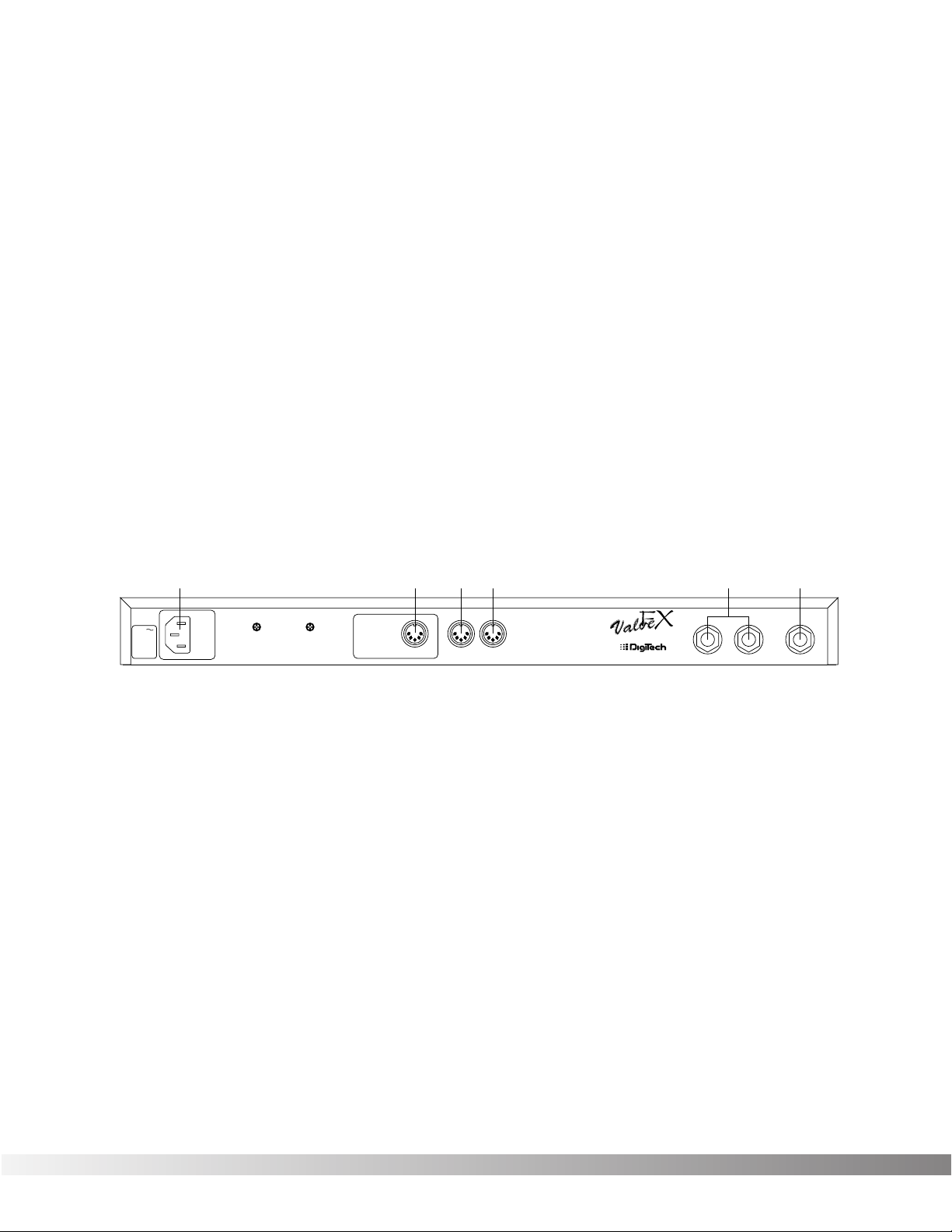
REAR PANEL CONNECTIONS The Valve FX rear panel connectors and functions are as follows:
1) AC Line Input - This is the power cord receptacle.
2) Foot Controller - This 5-pin DIN plug is for connecting the optional
DigiTech Control One foot controller. THIS IS NOT A MIDI PORT.
CONNECTING A DEVICE OTHER THAN THE DIGITECH CONTROL
ONE FOOT CONTROLLER TO THIS JACK MAY DAMAGE THE
DEVICE. A standard MIDI-type 5-pin DIN connector was chosen
for the Control One foot controller connector because cables are so
readily available.
3) MIDI In - The MIDI In port allows the Valve FX to respond to incom-
ing MIDI messages, including Program Change, Continuous
Control, and System Exclusive data.
4) MIDI Out - Sends out MIDI data generated by the Valve FX to
other devices. It can also pass MIDI data received by the Valve
FX’s MIDI In to other devices.
Section 1 - Startup
Valve FX Owner’s Manual
123456
120 V
60 Hz
30 WATTS
FUSE:
200 mA 250 V
SLOW BLOW
WARNING: This
jack is not a MIDI
connection.
Connecting a MIDI
device to this jack
may damage the
FOOTSWITCH
device.
MIDIINMIDI
OUT
CAUTION: TO REDUCE THE
RISK OF FIRE REPLACE ONLY
WITH SAME TYPE FUSE.
ATTENTION: UTILISER UN
FUSIBLE DE RECHANGE DE
MEME TYPE.
MANUFACTURED
IN THE
USA BY
SALT LAKE CITY, UTAH
LEFT (MONO) INPUTRIGHT
Page 10
9
5) Outputs - These are the main left and right audio outputs of the
Valve FX. Use both outputs when possible since Programs are set
up to take advantage of stereo effects. When the Output mode is
set to mono, either output can be used.
6) Input - This is the audio input to the Valve FX. Plug your instru-
ment in here. This input is disengaged when the front panel input
is used.
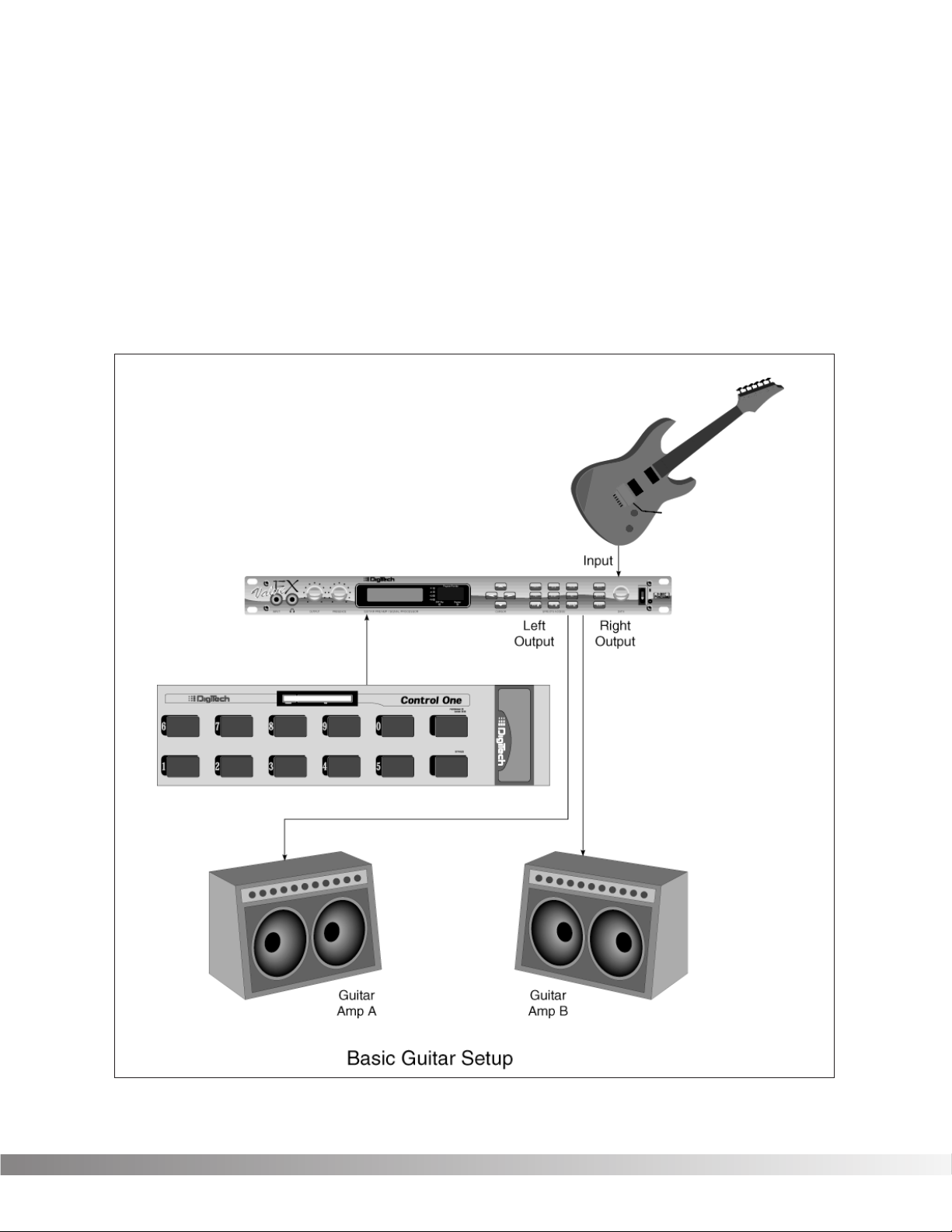
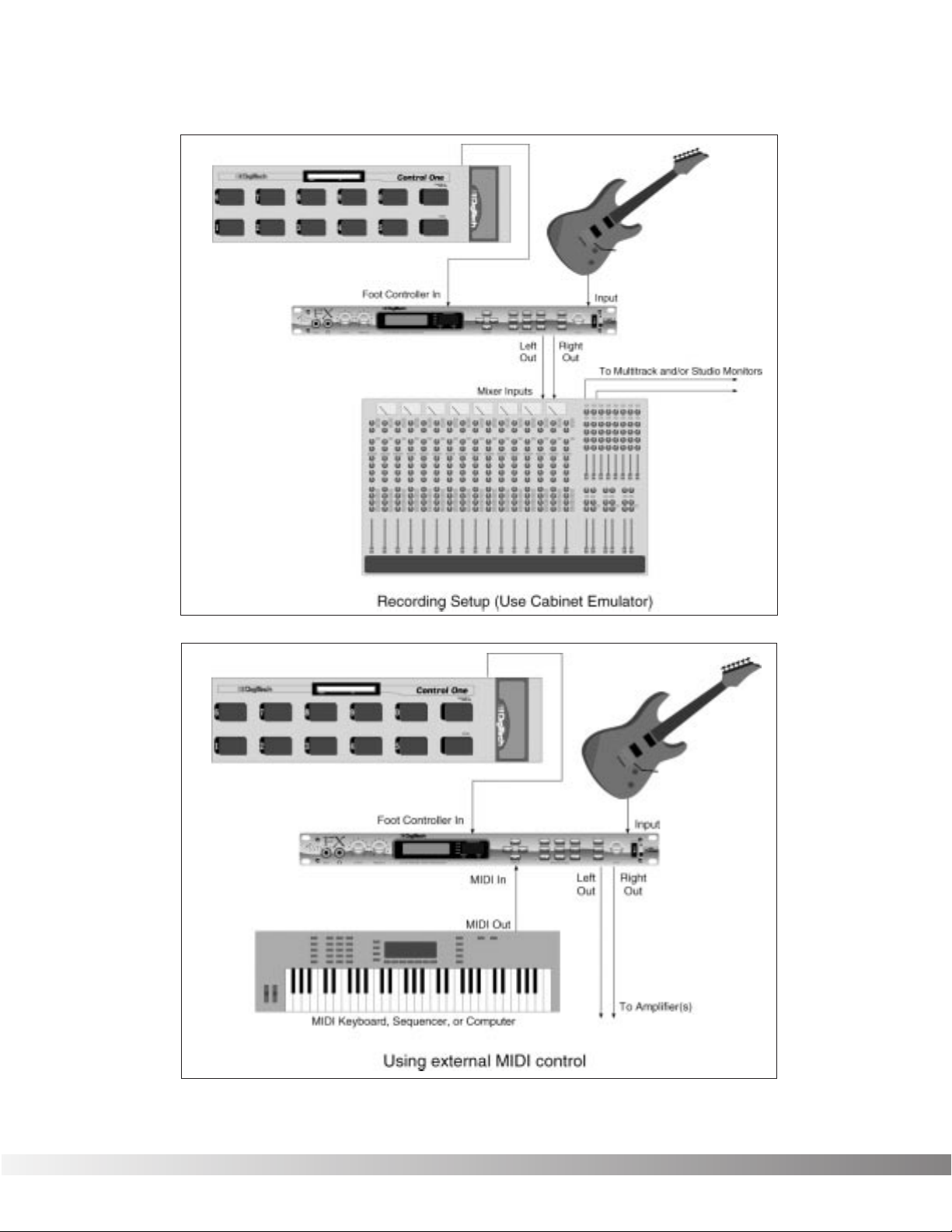
MIDI AND AUDIO SETUPS The following diagrams show possible MIDI and audio routing setups
for the Valve FX.
Section 1 - Startup
Valve FX Owner’s Manual
Page 11
10
Section 1 - Startup
Valve FX Owner’s Manual
Page 12
11
SECTION 2 - BASIC OPERATIONS
MAIN OPERATING MODE After the Valve FX powers-up, the current Program title screen is dis-
played. This is the main operating mode for the Valve FX from which
any of the operating Parameters can be easily reached and modified.
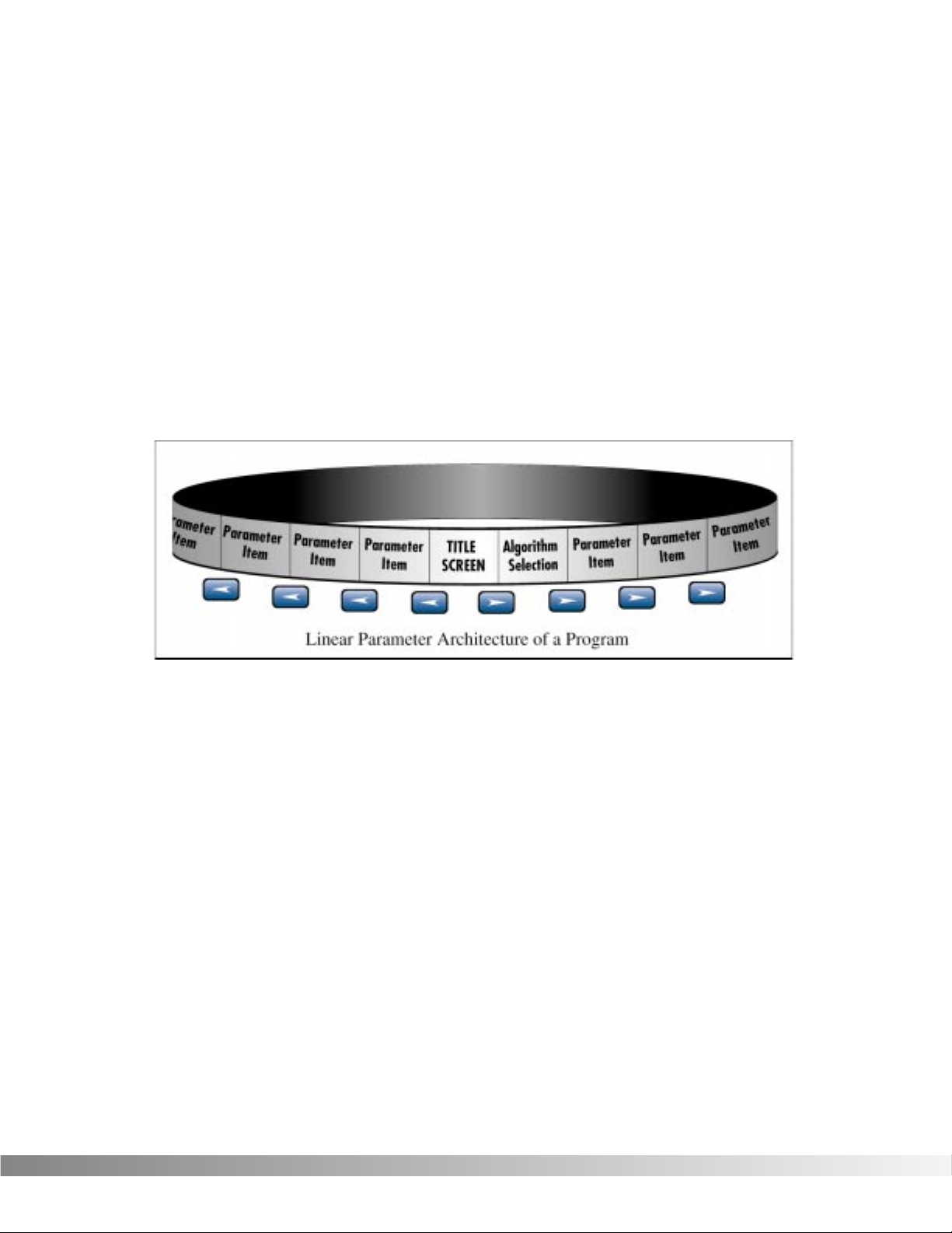
PARAMETER ARCHITECTURE The Program’s Parameter architecture in the Valve FX has been
designed to be a linear series of items rather than a multiple-level
menu (see diagram). In other words, instead of including several submenus, or levels, under a single Parameter heading, all Parameters
and functions are included in a single level, and are accessed using
the <LEFT> and <RIGHT> Cursor keys. This makes access to specific Parameters of a Program quick and easy, and provides a much
clearer picture of exactly where you are in the menu.
The diagram above shows the linear arrangement of Parameters in the
Valve FX. Notice that if you press the <RIGHT> Cursor key from the
last item in the list (the Parameter item to the left of the title screen),
the display jumps, or “wraps around to” the first item in the menu (in
this case, the title screen).
Likewise, if the <LEFT> Cursor key is pressed from the title screen,
the display will wrap to the last Parameter in the list. This wraparound
menu feature is provided so that Parameters that appear near the end
of a long list of items can be just as easily reached as items near the
beginning of the menu. If you press and hold either the <LEFT>
Cursor key or the <RIGHT> Cursor key, the Valve FX will begin
scrolling at high speed through the available Parameters in the
Parameter menu.
Section 2 - Basic Operations
Valve FX Owner’s Manual
Page 13

12
ACCESSING FACTORY PROGRAMS There are four methods for recalling Programs. The first method uses
the <UP> and <DOWN> Cursor keys. The procedure is as follows:
• From the title screen, press the <UP> Cursor key. Note that the
Program shown in the display changes and the number shown
in the LED display increments by one each time the <UP>
Cursor key is pressed. Pressing the <DOWN> Cursor key causes the reverse to occur: the Valve FX decrements through the
Programs in memory.
• To scroll at high speed through the Programs in memory, press
and hold either the <UP> or <DOWN> Cursor key.
The second method for changing Programs is the same as the first,
except that instead of using the Cursor <UP> and <DOWN> keys,
turn the Data wheel. Turning the Data wheel clockwise from the title
screen increments through Programs, while turning it counter-clockwise decrements through Programs.
The third method uses the optional Control One foot controller.
NOTE: When you send a Program change to the Valve FX using
the optional Control One foot controller, any unstored modifications you have made will be lost.
The procedure is as follows:
• Press the Select switch (in the upper right corner of the Control
One foot controller) once. The foot controller display reads:
• Using the numbered foot switches, enter the number of the
Program you want to recall. If the Program number is only two
digits long, press the Select switch again to accept the selected
Program number.
The fourth method is through the use of MIDI. This method will be
covered later in the Utilities section of this manual, pg. 44.
PROGRAM NUMBER
Section 2 - Basic Operations
Valve FX Owner’s Manual
Page 14

13
SECTION 3 - PROGRAMMING
USING THE FUNCTION KEYS The Valve FX has three Function keys that perform several functions in
different menus. They are located in the bottom row of the Effects
Access keys and they share buttons with the <MOD ¡>, <MIX ™>,
and <MORE £> options. Each Function key is numbered and performs several functions in the Utility mode (depending on the selected
menu screen). These keys are also used in the Program naming
process (see Storing / Naming Programs, pg. 17). For more on the
Utility and MIDI Menus, see pg. 44.
¡Indicates that Function key 1 performs the function shown in the
display.
™Indicates that Function key 2 performs the function shown in the
display.
£Indicates that Function key 3 performs the function shown in the
display.
MORE SPECIAL CHARACTERS There are several special characters that the Valve FX uses to tell you
at a glance exactly what it is doing. All special characters in the
Valve FX (except CC) are in inverted type, that is, reversed out of a
black background, and they will usually appear in the upper righthand corner of the display.
ß Indicates that the Cabinet Emulator is currently active.
Ç Indicates that a MIDI continuous controller is linked to the
Parameter.
å∫Characters from this group are used for distinguishing
between redundant Modules in a single Algorithm. This special character will immediately follow the Module name rather than appear in
the corner of the display.
Section 3 - Programming
Valve FX Owner’s Manual
Page 15
14
THE EFFECTS ACCESS KEYS The Effects s are used to jump to specific places in menus. For
example, if a Program contains several delays and you want to
change the delay time on only one of them, you could press the
<DLY/SMP> Effects Access button from Program’s title screen and
you would be jumped to the first Parameter of the first delay in the
Algorithm. Press the button again, and you are taken to the first
Parameter of the next delay in the Algorithm, and so on.
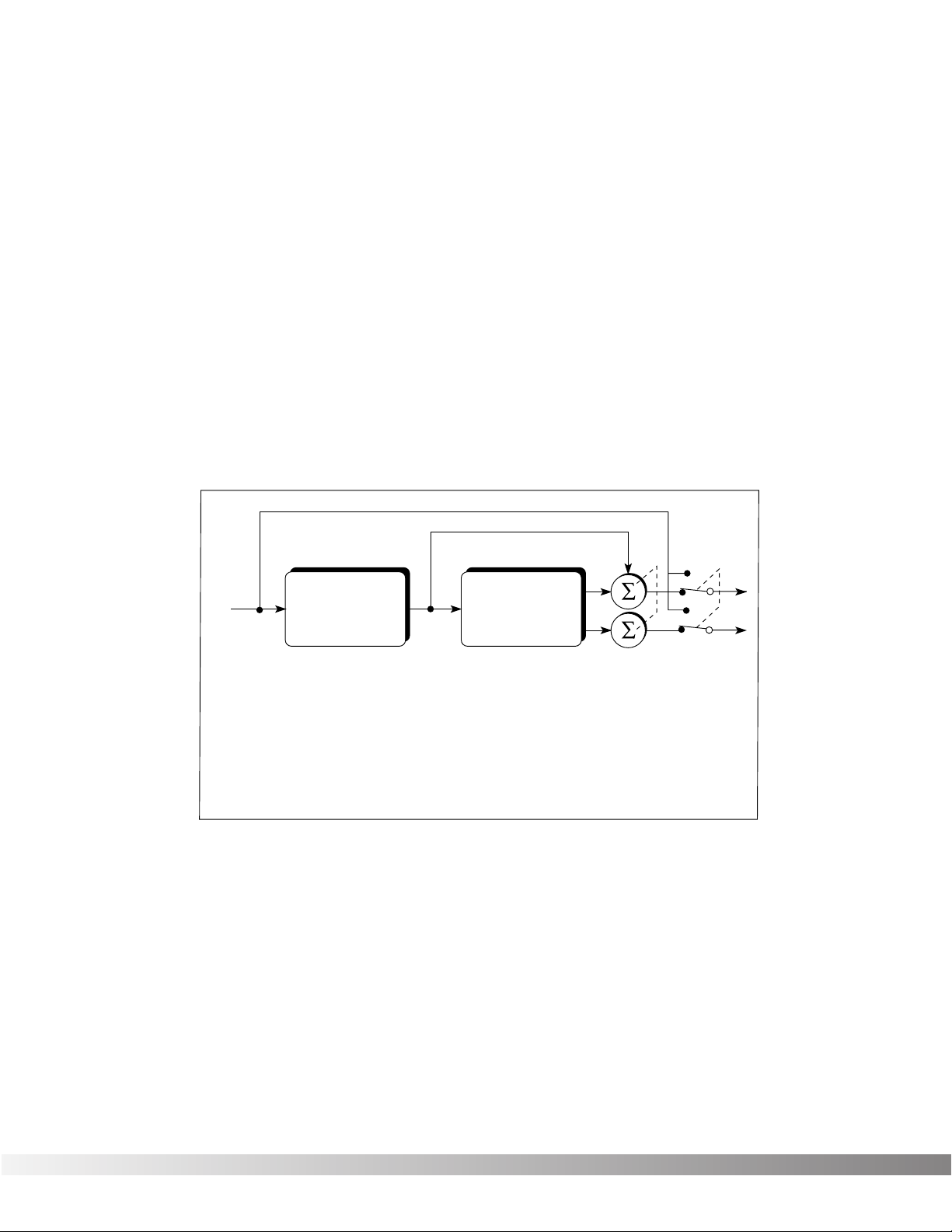
ABOUT THE I /O MODULE Each Program in the Valve FX is equipped with Compression,
Distortion, Clean / Distortion Level, Noise Gate, DSP Master Level,
Parametric EQ, and Cabinet Emulator controls. These items are permanent residents of every Algorithm in the unit.
This group of items is called the Input / Output Module (or I/O Module)
because they are always a part of both the input and output audio
paths of the Valve FX. The following diagram shows how the I/O
Module affects the signal as it flows through the unit.
The Valve FX’s Compression, Distortion, and Clean / Distortion Level
are analog for warmth and power. The Noise Gate, DSP Master Level,
Parametric EQ, and Cabinet Emulator are all accomplished in the digital realm for absolute flexibility and precision.
MODIFYING FACTORY PROGRAMS After you’ve had time to familiarize yourself with the Valve FX, you may
find that there are several factory Programs that are very close to what
you’re looking for, but that need a few small tweaks to get them perfect. The effects used in each Program are arranged as Algorithms
and are explained in more detail on page 15.
Section 3 - Programming
Valve FX Owner’s Manual
Bypass Switch
I / O
From Inst.
Module
Compression (A)
Distortion (A)
Clean / Dist Level (A)
Noise Gate (D)
DSP Master Level (D)
Parametric EQ (D)
Cabinet Emulator (D)
Algorithm
(Digital Section)
Reverb
Delay / Sampler
Modulation
Pitch Shift
Mixers
Etc...
To Outputs
Master Mix (D)
A = Analog
D = Digital
Page 16

15
Program 105 (Infusion) has a Whammy™, a chorus, and a 200 millisecond stereo delay. Let’s suppose that in order to work in your
application, it needs to have a 425 millisecond delay. Using this
Program as an example for Program modification, the procedure for
changing the delay time is as follows:
• From the Program title screen, scroll to Program 105 using the
<UP> and <DOWN> Cursor keys or the Data wheel. The display reads:
• Using the <RIGHT> or <LEFT> Cursor keys, scroll to the DELAY
TIME Parameter. The display reads:
NOTE: By pressing the <DLY/SMP> key you can skip directly
to the first Parameter of the Delay effect in the Algorithm and
continue scrolling with the <RIGHT> Cursor key to the desired
Parameter.
The cursor appears under the 2 and the entire number is
enclosed in parenthesis indicating that this is the stored value for
that Parameter.
IMPORTANT:Delay Time Parameters in the Valve FX are
editable in two different ranges, giving the most flexibility and
accuracy in the least amount of scrolling time. In this example
Parameter, the cursor appears under the 2 in 0.200. The 2
resides in the hundred milliseconds position. In other words,
if you press the <UP> Cursor key when the cursor is in this
position, you will increase the delay time by 100 milliseconds.
If you press the <RIGHT> Cursor key, the cursor will move to
the third position to the right of the decimal point (0.200), or
milliseconds position. Each press of the <UP> Cursor key
from this position increases the delay time in single millisecond steps. Using this method of ranging allows you to scroll
rapidly to large-value delay times without having to wait for the
unit to scroll to it in single millisecond steps.
• Using the <UP> Cursor key, scroll upward until the hundreds
position shows a 4. The display reads:
Delay Time
0.400
Delay Time Tap 1
(0.200)
Infusion
Wah≥Wham≥Cho≥Dly
Section 3 - Programming
Valve FX Owner’s Manual
Page 17

16
• Press the <RIGHT> Cursor key once. The cursor moves to the
milliseconds position.
• Using the <UP> Cursor key, scroll until the last two digits of the
delay time read 25. The delay time is now set at .425 seconds.
If you change Programs at this point, either through MIDI or via the
front panel, any modifications that you have made to the Program will
be lost. In order for the Valve FX to remember the changes that you
have made, you must store the Program in memory. The procedure
for storing Programs is covered in more detail in Section 3, pg. 17.
BASIC PROGRAM CREATION There are several requirements for creating a Program on the Valve
FX. The first is that an Algorithm needs to be assigned to the
Program; second, Parameters must be modified to your liking, and
third, the Program must be stored in memory in order to be recalled
for later use.
SELECTING AN ALGORITHM The Algorithm you choose for a Program determines the basic func-
tion of the Program. It is therefore necessary to choose an Algorithm
that contains all the Modules you want to use in an appropriate configuration. For a complete list of the available Algorithms in the Valve
FX, see Section 6 on page 69. The Algorithm selection screen for all
Programs in the Valve FX is one screen to the right of the title screen.
The Algorithm selection screen works in conjunction with the LED display to show the Algorithm number When in the Algorithm selection
screen, the LCD display looks something like this:
Press the <UP> or <DOWN> Cursor keys from the Algorithm selection
screen, the LED display to the right of the screen shows an A followed by the Algorithm’s number. To select an Algorithm for a
Program, the procedure is as follows:
• From the title screen, press the <RIGHT> Cursor key once. This
is the Algorithm selection screen. The name of the currently
selected Algorithm is shown on the top line of the display, while
the bottom line shows the effects in the Algorithm.
NOTE: When there are more effects in the Algorithm than will
fit on a single line of the display, an arrow will appear in the
first and/or last character of the bottom line of the display.
These arrows indicate that there is more information about the
effects that could not be displayed on a single screen. To
see the remaining information, simply press the <RIGHT> or
<LEFT> Cursor key (depending on the arrow direction indicated in the display).
Wham≥2TDly≥Revrb
Comp Dist MVol≥
Section 3 - Programming
Valve FX Owner’s Manual
Page 18

17
• Use the <UP> and <DOWN> Cursor keys to select the
Algorithm you want to use with the Program. The LED display
now shows the Algorithm number as you scroll up or down.
• Use the <RIGHT> and <LEFT> Cursor keys to begin modifying
the Parameters of the currently selected Algorithm to suit your
purpose.
NOTE: When you change the currently selected Algorithm,
the default Parameters selected for the new Algorithm are
taken from the first Program in memory that uses it.
Once you have selected the Algorithm you want to use and modified
its Parameters, an asterisk appears in the upper right corner of the
title screen. This asterisk indicates that the Program has been modified and any changes you have made will be lost if not stored in the
Valve FX’s memory.
STORING / NAMING PROGRAMS In order for modified Programs to be available for later recall, you
must store them in memory. This is accomplished using the
<STORE> key. The Valve FX also allows you to give your Programs
custom names up to 15 characters in length. The naming procedure
uses the <UP> and <DOWN> Cursor keys, the Function keys, and/or
the data wheel to make Program naming extremely quick and easy.
The <MOD ¡> key changes the character from upper to lower case
and back. The <MIX ™> key places a space into the Program name,
and the <MORE £> key instantly jumps you to the numbers section of
the character set. The complete procedure for storing and naming a
Program is as follows:
• After you have made all the necessary modifications to the
Algorithm, press the <STORE> button once. The Valve FX is
now in Name mode. The display shows:
The blocked numbers preceding each option on the bottom line
indicate the Function key that will perform the function shown.
• Using the <UP>/<DOWN> Cursor keys or the Data wheel, scroll
to the character you want to use, or press one of the Function
keys. When you have selected the character you want, press
the <RIGHT> Cursor key. Note that the cursor moves to the
next character. Repeat this procedure until the Program name
is satisfactory.
Unique to the Valve FX naming process are several special naming
[PROGRAM NAME]
¡CAPS ™SPC £NUM
Section 3 - Programming
Valve FX Owner’s Manual
Page 19

18
functions. The <REV> and <PITCH> keys allow you bump an entire
name or section of a name either left or right in one-space increments.
The procedure is as follows:
• In Name mode, use the <RIGHT> and <LEFT> Cursor keys to
place the cursor underneath the character to be moved.
• Press the <REV> or <PITCH> keys to move the characters
either left or right.
The <CMP/DIST> key copies the character under which the cursor
sits into memory. This allows you to place a copy of that character
(using the <DLY/SMP> key) anywhere else in the name that you want.
The procedure is as follows:
• In Name mode, use the <RIGHT> / <LEFT> Cursor keys to
place the cursor under the character to be copied.
• Press the <CMP/DIST> key. The selected character is copied
into memory.
• Move the cursor to the location into which you want to place a
copy of the character and press the <DLY/SMP> key. A copy of
the character appears in the location you selected.
• When the Program name appears as you want it, press the
<STORE> key. The display reads:
This screen allows you to select the location in which you want to
store the new Program.
• Using the <UP>/<DOWN> Cursor keys, scroll to the Program
number location in which you want to store the new Program.
• To store the Program in the selected location, press the
<STORE> key again. The display briefly reads:
after which you will be returned to the previous mode. To abort
the command, press <EXIT>.
***Storing***
Store To Prg ##
[PROGRAM NAME]
Section 3 - Programming
Valve FX Owner’s Manual
Page 20

19
The Store function can also be used to copy Programs from one memory location to another. If no changes have been made to the selected Program and the <STORE> key is pressed, the Valve FX is placed
in Name mode; press the <STORE> key a second time and the display reads:
Select the memory location in which you want to place a copy of the
selected Program using the <UP>/<DOWN> Cursor keys, and press
<STORE> again. The display briefly reads:
after which you will be returned to the previous mode. To abort the
command and return to the naming screen, press <EXIT>.
***Copying***
Copy To Prg ##
[PROGRAM NAME]
Section 3 - Programming
Valve FX Owner’s Manual
Page 21

20
SECTION 4 - EFFECTS AND PARAMETERS
ABOUT THE EFFECTS LIBRARY The Effects Library consists of all the effects Modules you can find in
the Valve FX. Broken down into individual categories, specific
Modules and their abbreviated library names are as follows:
The analog section of the Valve FX includes the compressor and the
distortion section. These two items are always available in all
Programs.
COMPRESSOR The Valve FX’s compressor is a high-quality, low-noise circuit special-
ly designed for guitars. Compression can be used to increase sustain
and to tighten up guitars, and is particularly useful on clean sounds.
Parameters of the Valve FX compressor are as follows:
Comp On / Bypass .......Turns the Module on or off. When Modules
are bypassed their Parameters disappear
from the Parameter menu. To see the
Parameters, you must turn the Module on.
Comp Amount ...............Controls the amount of compression applied
to the signal. Higher settings yield a tighter,
more focused sound, while lower settings
allow better dynamics. Ranges from 0 to 31.
Comp Level...................Sets the output level of the compressor before
feeding to the distortion. Higher settings send
more signal level into the distortion, yielding
extra gain and drive. Varies from 1 to 7.
DISTORTION The distortion section of the Valve FX provides six distinctly different
types of distortion. There are three tube-driven (12AX7) voicings and
three are solid-state distortion sounds ranging from a light overdrive
tone to a screaming grunge. The Overdrive and Heavy Sustain settings offer classic distortion sounds while the Grunge setting provides
extremely high-gain distortion, without the mush and tonal sacrifices
found in other manufacturers’ products. The Tube distortions give you
the added warmth, touch, power, and grind that only a tube can produce for a lethal combination of tube power with the programmability
of digital control.
Distortion
Compressor
Analog Effects
Module Name Description
Analog compressor tailored for instruments
Analog distortion (3 tube or 3 solid-state types)Distrt
Compr
Module Abbrv.
Section 4 - Effects and Parameters
Valve FX Owner’s Manual
Page 22

21
The Distortion Parameters are as follows:
Dist On / Bypass ...........Turns the Module on or off. When Modules
are turned off, their Parameters disappear
from the Parameter menu. To see the
Parameters, you must turn the Module on.
Distortion Type ..............Selects the type of distortion to be used in the
Program. Options are: SATURATED TUBE Hot, loud, and thoroughly modern grind of the
best tube amps and guitar rigs. Capable of
generating extremely high gain, but remains
quiet enough for use in any studio. DISTORTED TUBE - Great for heavy rhythms or gritty
leads. CLEAN TUBE - For sparkling, breathy
clean sounds. OVERDRIVE - Solid-state overdrive with extra punch. HEAVY SUSTAIN Smooth, warm distortion sound with lots of
sustain. GRUNGE - Tons of solid-state gain.
Tight and highly focused for powerful rhythms
and leads.
Distortion Gain ..............Controls the amount of distortion produced by
the Valve FX. High settings produce greater
gain and drive for effortless soloing, while low
settings offer better control of playing nuances
and touch. Ranges from 0 to 11.
Dist/Clean Level ............This Parameter allows two separate levels to
be set. If the Distortion is turned on, the
Distortion level can be adjusted. If the
Distortion is turned off, the Clean level can be
adjusted. Both level settings are saved when
the Program is stored. Settings include MUTE
or ranging from -60dB to +12dB.
Section 4 - Effects and Parameters
Valve FX Owner’s Manual
Page 23
22
4-BAND PEQ / 10-BAND GEQ The equalizer Modules provided in the Valve FX offer superb noise
performance, and allow accurate tonal shaping of many different
types of sound sources. There is a standard 4-band parametric
equalizer with adjustable Q available in all Algorithms. The Valve FX
also features a 10-band graphic equalizer in select Algorithms. All
equalizer Modules offer silent, hyper-accurate (double-precision) for
tonal shaping.
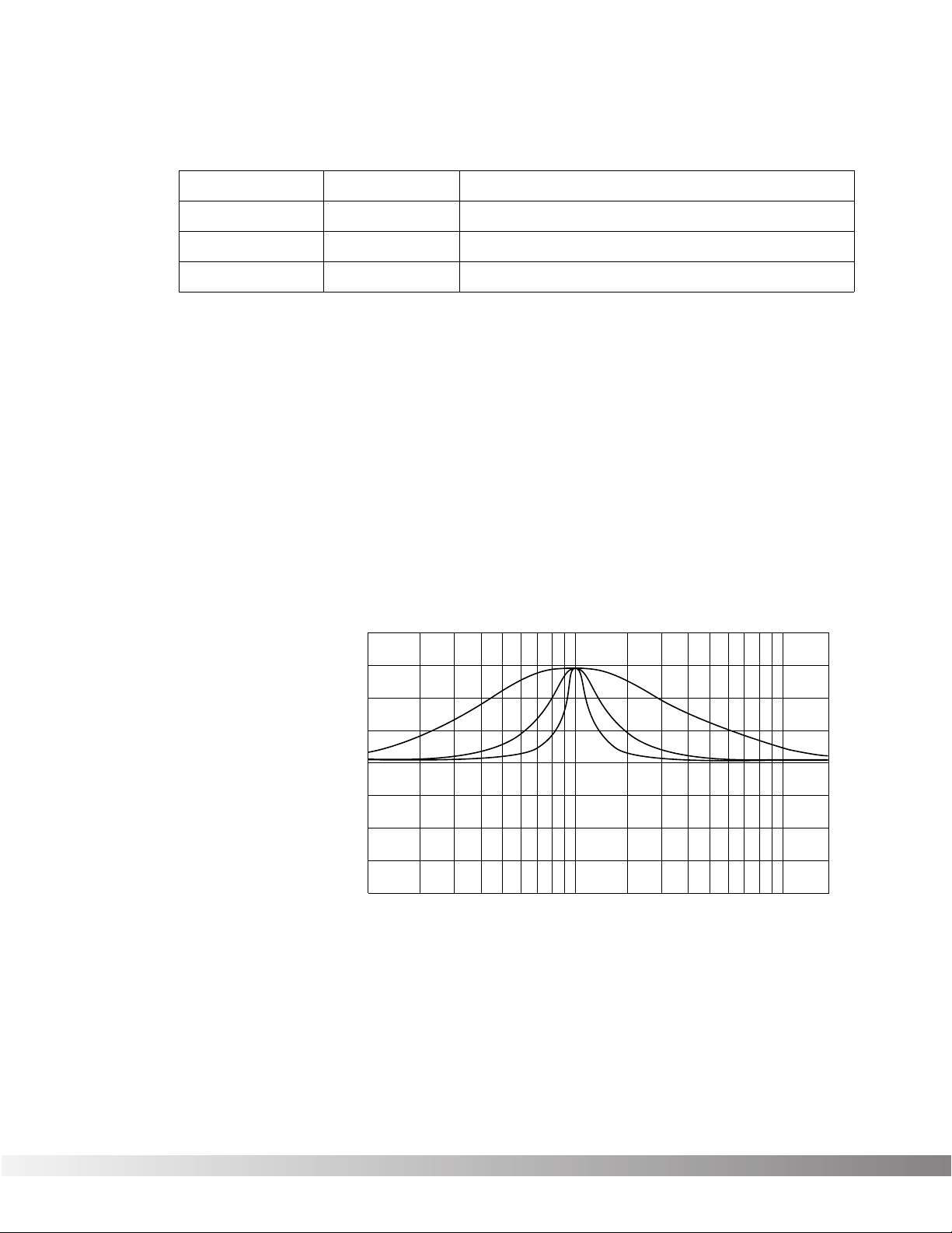
Adjustable Q equalizers offer the ability to control the bandwidth of
the boost/cut ranges. High Q settings yield extremely narrow bandwidth, where boost and cut have minimal effect on adjacent frequencies of the program material. Low Q settings affect a wider number of
frequencies when the selected band is boosted or cut.
With a Q setting of 2, you can see that a large number of frequencies
are affected by boosting the center frequency. Now take a look at the
middle and lower curves in the diagram, and notice the much narrower bandwidth of the curves with a Q setting of 4 and 8.
Section 4 - Effects and Parameters
Valve FX Owner’s Manual
Equalizers
Module Name
10 Band GEQ
4Bnd ParamtrcEQ
Cabinet Emulator
Module Abbrv.
GEQ10
PEQ4
CabEm
DigiTech Audio Precision STD AMPL (dBr) vs FREQ (Hz)
20.000
Description
Full bandwidth 10-band graphic equalizer
4-band parametric equalizer w/adjustable Q
Full-bore stack sound direct-to-console
15.000
10.000
5.0000
0.0
-5.000
-10.00
-15.00
-20.00
100 1k 10k
Q = 2
Q = 4
Q = 8
20k
Page 24

23
CABINET EMULATOR The Valve FX’s programmable Cabinet Emulator circuitry allows you to
use it in both recording and live situations without lugging heavy
amps and/or cabinets around. Just connect the Valve FX outputs to a
mixing console and kick in the Cabinet Emulator. No miking hassles,
no heavy equipment; just a full-on miked cabinet sound. Programs
can be stored with different Cabinet Emulator settings so you can customize your banks or setlists for whatever sound types you need.
Parameters are as follows:
Effect On / Bypass ........Turns the Module on or off. When Modules
are turned off, their Parameters disappear
from the Parameter menu. To see the
Parameters, you must turn the Module on.
Cabinet Type.................Selects the tonal characteristics of the simulat-
ed cabinet. There are 10 different cabinet
types; 3 warm cabinets, 3 medium cabinets, 3
bright cabinets, and 1 full bandwidth cabinet
for maximum frequency response. The full
bandwidth cabinet is useful when the Cabinet
Emulator is set globally on (in the Utility menu)
and a full bandwidth sound is still desired.
Section 4 - Effects and Parameters
Valve FX Owner’s Manual
Page 25

24
BIGVERB / MFX REVERB Bigverb is the flagship reverb Module of the Valve FX. It contains 14
Parameters, giving exceptional soundfield and tonal shaping control
over reverberation. Bigverb is capable of producing reverberation of
virtually any size, shape, depth, timbre or soundfield location.
MFX Reverb is a slightly trimmed version of the Bigverb, offering much
of the same flexibility and controls as Bigverb, but in less memory
space. MFX Reverb allows you to achieve high-quality reverb in conjunction with other effects.
Before covering all the reverb Parameters and their definitions in
detail, however, let’s discuss the benefits and theory behind reverberation Algorithms.
Ambience, or reverberation, is produced when sound energy is
reflected off room surfaces and objects. Using reverberation in
recorded program material gives the listener a sense that the material
is being performed in an actual room or hall. It is this similarity to
actual acoustic spaces that makes reverberation a useful tool in
recorded music.
The length of the reverberation, or reverb time, can be perceived by
the listener and is useful during the course of continuous program
material (reverb time is defined as “the length of time the reverberation takes to decay to inaudibility”, or -60 dB). Studies have shown
that the character of reverberation depends heavily upon the initial
buildup and decay of the reverberation reflections.
The Valve FX uses early reflections to better emulate the natural
sound of a hall. Early reflections are short clusters of direct reflections
from the closest room walls. In an average size hall, these direct
reflections usually occur within the first 30 to 100 milliseconds,
depending on the size of the room and the placement of the sound
source within the room. Adding these early reflections to the reverberation increases the perceived reverberation time and the apparent
size of the reverberant space, but adding more than small amounts
tends to make the reverb sound unnatural.
Reverbs
Module Name DescriptionModule Abbrv.
BigVerb Studio-quality reverb.Big
MFX Reverb Reverb used in multi-effects Algorithms.MVerb
Gated Reverb Professional gated reverbGtRvb
Section 4 - Effects and Parameters
Valve FX Owner’s Manual
Page 26

25
The BigVerb’s ER SPREAD, ER SHAPE and ER DIFFUSION controls
allow you to modify the build/decay of the early portion of the reverberation envelope and the relative reverberation time of the midrange
reverb frequencies. The ER SHAPE Parameter controls the shape of
the early reflection envelope. The ER SPREAD sets the time over
which this early reflection shape is achieved, and the ER DIFFUSION
controls the smoothness of the early reflection. A chart showing all 10
early reflection shapes can be found on Pg. 26.
The RV SIZE control is the master control for the apparent room size.
The RV RT60 Parameter varies in relation to the setting of the RV SIZE.
This means that as RV SIZE is modified, the RV RT60 Parameter
changes to correspond with the selected room size (the RV RT60
value is calculated automatically). The RV SIZE Parameter, on the
other hand, does not vary when RV RT60 is modified.
These few controls, in conjunction with the RV DIFFUSION, RV HIFREQ DECAY, and RV HI-FREQ ROLLOFF controls, give your simulated environment its reflectivity characteristics, and can be used to simulate the presence of nearly any type of large-area reflective surface
in a reverberant space, such as wood, carpet, glass, metal, etc.
A M P L I T U D E
T I M E
SUBSEQUENT REVERBERATIONS
RV PRE-DELAY
RV SIZE
EARLY
REFLECTIONS
EARLY RFLCT
PREDELAY
INITIAL
SOUND
Section 4 - Effects and Parameters
Valve FX Owner’s Manual
Page 27

26
Now that we better understand all the aspects and properties of
Reverb, the Parameters of the Reverb modules are as follows:
Reverb On / Off.............Turns the Module on or off.
ER Predelay ..................Controls the length of time before the early
reflections are heard. Ranges in milliseconds
from 0 to 100. (ER settings in BigVerb only.)
ER Spread.....................Controls the length of time over which the
early reflections occur. Low settings yield a
dense, smooth cluster of early reflections
while higher settings spread the same number
of reflections out over a longer period of time.
Ranges from 25 to 300 milliseconds. (ER settings in BigVerb only).
ER Shape ......................Controls the shape of the early reflection
envelope. There are 10 different early reflection envelope shapes. The following diagram
shows all the available early reflection envelope shapes. The numbers across the top of
each envelope shape graph represent the relative level of the signal at each point in the
envelope. (ER settings in BigVerb only.)
ER Diffusion
...................Controls the smoothness of the early reflec-
tions. Ranges from 1 to 10. (ER settings in
BigVerb only.)
ER Level ........................Master level control for early reflections.
Ranges from 0 to 100. (ER settings in
BigVerb only.)
-20 dB
0 dB
TIME
AMPLITUDE IN dB
SHAPE = 1
-5 dB
-10 dB
-15 dB
-20 dB0 dB -5 dB -10 dB -15 dB
-20 dB
0 dB
TIME
AMPLITUDE IN dB
SHAPE = 2
-5 dB
-10 dB
-15 dB
-20 dB-3 dB -2 dB -8 dB -14 dB
-20 dB
0 dB
TIME
AMPLITUDE IN dB
SHAPE = 3
-5 dB
-10 dB
-15 dB
-20 dB-5 dB 0 dB -6.6 dB -13.3 dB
-20 dB
0 dB
TIME
AMPLITUDE IN dB
SHAPE = 4
-5 dB
-10 dB
-15 dB
-18 dB-10 dB -3 dB -2 dB -10 dB
-20 dB
0 dB
TIME
AMPLITUDE IN dB
SHAPE = 5
-5 dB
-10 dB
-15 dB
-15 dB-15 dB -7.5 dB 0 dB -7.5 dB
-20 dB
0 dB
TIME
AMPLITUDE IN dB
SHAPE = 6
-5 dB
-10 dB
-15 dB
-10 dB-18 dB -10 dB -2 dB -3 dB
-20 dB
0 dB
TIME
AMPLITUDE IN dB
SHAPE = 7
-5 dB
-10 dB
-15 dB
-5 dB-20 dB -13.3 dB -6.6 dB 0 dB
-20 dB
0 dB
TIME
AMPLITUDE IN dB
SHAPE = 8
-5 dB
-10 dB
-15 dB
-3 dB-20 dB -14 dB -8 dB -2 dB
-20 dB
0 dB
TIME
AMPLITUDE IN dB
SHAPE = 10
-5 dB
-10 dB
-15 dB
-5 dB-10 dB -10 dB -5 dB -3 dB
-20 dB
0 dB
TIME
AMPLITUDE IN dB
SHAPE = 9
-5 dB
-10 dB
-15 dB
0 dB-20 dB -15 dB -10 dB -5 dB
Section 4 - Effects and Parameters
Valve FX Owner’s Manual
Page 28

27
RV Predelay ..................Controls the amount of time before the first
room reverberations are heard. In an actual
acoustic space, the amount of reverberation
predelay depends largely on the shape and
size of the room and the placement of both
listener and sound source within the room.
Long RV PREDELAY settings place the reverberation after the program material rather than
in sync with it. Ranges in milliseconds from 0
to 100.
RV Spread.....................Controls the dispersal and density of reverber-
ations through the course of the early portion
of RV RT60. BigVerb’s RV SPREAD varies in
20 ms increments from 20-180 ms. MFX
Reverb’s RV SPREAD varies in 10 ms increments from 10-100 ms.
RV Diffusion...................RV DIFFUSION controls the smoothness of the
reverberation. In a real room, reverberation is
naturally diffused by air. However, diffusion
can also be affected by temperature, humidity, and the presence of absorptive or diffusive
materials in the room. Ranges from 1 to 10.
RV Hi-Freq Decay .........Controls the decay length (damping) of the
high frequency reverberations. Variable from
25Hz to 20 kHz.
RV Hi-FrqRolloff.............This is a low-pass filter that sets the rolloff fre-
quency of the reverberations. This is a bandlimiting control, and the frequencies above the
setting of this Parameter will be rolled off
rapidly. Variable from 25Hz to 20 kHz.
RV Size..........................Sets the apparent size of the reverberant
space. As the setting of RV SIZE is increased
or decreased, the setting of RV RT60 changes
to correspond with the new room size setting.
However, changing the setting of RV RT60
does not affect the setting of RV SIZE.
Ranges from 1 to 10.
RV RT60 ........................Controls the length (RT60) of the reverb after
the signal has stopped. Ranges in seconds
from 0.01 to 20.00.
RV Level ........................Sets the overall level of the reverberations.
Varies from 0 to 100.
Section 4 - Effects and Parameters
Valve FX Owner’s Manual
Page 29

28
GATED REVERB Gated reverbs usually include adjustable thresholds to set the point at
which the reverberations will be gated (cut off). The Valve FX’s RV
DECAY TIME control behaves in somewhat the same way, except that
instead of setting the length by level (threshold), the length is set by
time (in milliseconds). In the left side of the diagram that follows, you
can see that reverberations occurring after RVB GATE TIME are
muted. This causes the reverb to cut off abruptly.
Gated reverbs are most commonly used on percussion, but there are
other ways to employ the unique sound they produce. For instance,
using a REVERSE envelope shape, a reverse gate can be accomplished. Rather than decaying out to be cut off by the gate, a reverse
gate builds for a specific amount of time, and is cut off by the gate.
Reverse envelopes are similar in sound to playing a record backwards. The right diagram below shows how a Reverse envelope
works.
The accent point shown in the diagram allows placement of the actual
sound, either before or after the gate has cut off the reverberation.
The Valve FX offers three different envelope shapes in the Gated
Reverb Algorithm: DECAYING, FLAT, and REVERSE. DECAYING is a
standard gated reverb envelope, with a linear decay to the cutoff
point. In most applications, the DECAYING envelope doesn’t need an
accent point, although it can produce some interesting unnatural
sounds. In instances where an accent point is not needed, simply
turn down the left and right REVERB ACCENT DLY Parameters.
Using a FLAT envelope shape, the reverberation neither decays nor
builds, but remains at a constant level for a specified amount of time
(determined by the setting of RVB DECAY TIME). This shape is particularly useful for short, percussive sounds.
A REVERSE envelope allows creation of dramatic reverse gate reverb
effects, with placement of the accent point ±50 milliseconds either
before or after the end of RVB DECAY TIME.
ACCENT
A M P L I T U D E
T I M E
RVB DECAY TIME
MUTED
REVERBERATIONS
A M P L I T U D E
T I M E
RVB DECAY TIME
MUTED REVERBERATIONS
GATE
THRESHOLD
PRE
DELAY
INITIAL
SOUND
Section 4 - Effects and Parameters
Valve FX Owner’s Manual
Page 30

29
Gated reverbs can be found in the <REVERB> library, and their
Parameters are as follows:
Gated Reverb On / Off..Turns the Module on or off.
Reverb Pre-Delay..........Sets the amount of time before the reverbera-
tions are heard. Adjustable from 0 to 100 milliseconds.
Rvb Decay Time............Controls the amount of time before the gate
cuts off the reverberations. Variable from 20
to 1000 milliseconds.
Rvb Envelope................Sets the shape of the reverberation envelope
(DECAYING, FLAT, or REVERSE).
Rvb Diffusion.................Controls the smoothness of the reverbera-
tions. Variable from 1 to 10.
Rvb LPF Frequency ......Reverb low-pass filter. Sets the frequency
below which reverberations will be heard.
Adjustable from 25Hz to 20kHz.
Rvb Accent Delay .........Allows placement (in time) of the actual
sound, ±50 milliseconds from the reverb gate
point.
Rvb Accent Left ............Controls the level of the accent in the left side
of the stereo soundfield. Variable from 0 to
100.
Rvb Accent Right ..........Controls the level of the accent in the right
side of the stereo soundfield. Variable from 0
to 100.
Rvb Level Left ...............Sets the output level of reverberations heard
in the left channel. Variable from 0 to 100.
Rvb Level Right.............Sets the output level of reverberations heard
in the right channel. Variable from 0 to 100.
Section 4 - Effects and Parameters
Valve FX Owner’s Manual
Page 31

30
DELAYS All the delays in this group have the same basic Parameters for con-
trolling the behavior of the Module. General Parameters include
DELAY ON/OFF, DELAY LEVEL, DELAY TIME, DELAY FEEDBACK,
and DELAY REPEAT HOLD. The only differences between them lie in
the number of taps available and the total amount of delay time. The
multi-tap delays also include independent delay time controls for each
tap with a feedback control on the last tap in the series.
Each delay Module has a number that immediately follows the name.
These numbers represent, in seconds, the amount of delay time available to each Module. For example, if the Module name shown in the
display reads MONO DELAY 1.4S, you know that the Module has a
maximum of 1.4 seconds of delay time available.
The available delay time ranges are 0.4 seconds (400 milliseconds),
0.5 seconds (500 milliseconds), .8 seconds (800 milliseconds), 1.0
second (1000 milliseconds), and 1.4 seconds (1400 milliseconds).
Delay Parameters are as follows:
Delay On / Off ...............Turns the delay Module either on or off. When
Modules are turned off, their Parameters disappear from the Parameter menu. To see the
Parameters, you must turn the Module on.
Delay Level ...................Controls the level of the delay Module.
Variable from 1 to 100.
Delay Time (Tap #) .......Controls the delay time of the tap indicated in
the display. If a mono delay is used, no tap
number is shown. Delay time Parameters are
editable in two different ranges to give the
most flexibility and accuracy in the least
amount of scrolling time. If you press the
<UP> Cursor key when the cursor is in the
hundred milliseconds position (one place to
Delays/Sampler
Module Name
Mono Delay x.x
2Tap Delay x.x
4Tap Delay x.x
Stereo Delay
Description
1-tap digital delay
2-tap digital delay
4-tap digital delay
Stereo digital delay
Module Abbrv.
Dly
2TDly
4TDly
SDly
Modulated Delay Digital delay with pitch modulationModDly
Sampler 1.5 second samplerSmpl1.5
Section 4 - Effects and Parameters
Valve FX Owner’s Manual
Page 32

31
the right of the decimal), you will increase the delay time in increments
of 100 milliseconds. Pressing the <RIGHT> Cursor key moves the
cursor to the third position to the right of the decimal point, or milliseconds position. Each press of the <UP> Cursor key from this position
increases the delay time in single millisecond steps. Using this
method of ranging allows you to scroll rapidly to large-value delay
times without having to wait for the unit to scroll to it in single millisecond steps. Variable from 0.000 sec. to 1.400 sec.
Delay Feedback............Controls the amount of feedback, or number
of repeats, in the delay line. In multi-tap
delays, this Parameter controls the feedback
amount of the last tap in the series. Variable
from 0 (Off) to 99%.
Delay Repeat Hold........This is the infinite repeat Parameter. When
turned on, the delay taps will repeat indefinitely until the Repeat Hold Parameter is disengaged. This Parameter is either ON or OFF.
A M P L I T U D E
T I M E
INITIAL
SOUND
Fig. 3-4 Delay with Repeat Hold
0 dB
-30 dB
REPEAT
HOLD
A M P L I T U D E
T I M E
INITIAL
SOUND
Fig. 3-4 Delay Feedback at 50%
0 dB
-30 dB
Section 4 - Effects and Parameters
Valve FX Owner’s Manual
Page 33

32
SAMPLER The Valve FX offers a studio-grade sampler Module. It uses a 40 kHz
sample rate for great sound quality. Sample recording and playback
can be triggered from the external Valve FX switching device, or via
MIDI (through continuous controller linkages). Sampling can also be
triggered upon detection of a sound source. Parameters of Sampler
Modules are as follows:
Sampler On / Off ...........Turns the Module on or off.
Smpl Plybck Levl...........Determines the overall level of the sample
when played back. Varies from 0 to 100.
Smpl Looping................This Parameter has two settings: MANUAL
and AUTO. When this Parameter is set to
MANUAL: the sample must be triggered either
manually or using an audio trigger. When the
sample is finished playing, it resets and waits
for another manual trigger. When this
Parameter is set to AUTO, the sample begins
playing. When the sample is finished playing,
it is automatically retriggered from the beginning of the sample, and continues retriggering
until the Parameter is switched back to MANUAL.
Smpl Record/Play .........When set to RECORD, the sampler will record
a new sample into memory when triggered.
When set to PLAYBACK, the sample in memory will be played back when triggered.
Manual Trigger..............This Parameter allows manual playback trig-
gering of the sample in memory. To trigger
the sample, simply press the <UP> Cursor
key on this screen. To trigger the Sampler
using MIDI, link this Parameter to a MIDI CC
number (see Continuous Controller Links, pg.
48)
Smpl Triggr Mode .........Determines whether audio triggering or manu-
al triggering is active. There are two audio
triggering options and one manual triggering
option. They behave as follows: when set to
MANUAL TRIG, samples and sampling are
triggered using manual methods (footswitch,
front panel, etc.). When set to AUDIO TRG
ONCE, the sample is triggered once using an
audio source of a set level (determined by the
setting of INPUT TRIG LEVEL), following which
this Parameter is automatically reset to MANUAL. When set to AUDIO RE-TRIG, the sample
is retriggered any time a signal over the level
setting of SAMPLE TRIG LEVEL is detected.
Section 4 - Effects and Parameters
Valve FX Owner’s Manual
Page 34

33
Smpl Triggr Levl............Sets the level at which the audio signal will
trigger the sample. Variable from 0 to 100.
Smpl Direct Levl............Sets the level of the dry (non-effected) sound.
Variable from 1 to 100.
Smpl Start Point.............Determines the point at which the sample will
begin playing after it has been recorded. This
Parameter can be used to eliminate unwanted
sounds at the beginning of the sample, such
as empty space (silence), fret noise, amplifier
buzz, wrong notes, etc. Each time this
Parameter is changed, the sample is retriggered. This allows easy editing of start sample points. This control can be set at any
point in the sample below the setting of SAMPLE END. Like the DELAY TIME Parameter in
delay Modules, this Parameter is controlled in
two ranges. Refer to the section in the owner’s manual on controlling the delay time of a
delay Module for explanation of the ranges.
Smpl Stop Point.............Determines the point at which the sample
stops playing. This Parameter can be used to
eliminate unwanted sounds from the end of
the sample. This Parameter can be set at any
point in the sample above the setting of SAMPLE START. Like the DELAY TIME Parameter
of delay Modules, this Parameter is controlled
in two ranges. Refer to the section on controlling the delay time of a delay Module for an
explanation of the ranges.
Section 4 - Effects and Parameters
Valve FX Owner’s Manual
Page 35

34
The <PITCH> group includes pitch shifters, mono and dual detuners,
arpeggiators and DigiTech’s exclusive Whammy™.
Pitch shifters allow you to change your input note by a specified interval and mix it with the original, creating a totally new note. The effect
is similar to two or more guitars playing different notes simultaneously.
Detuning is similar in sound to a chorus, except that its pitch remains
constant, rather than modulating back and forth between two points.
It is best visualized in terms of two guitar strings tuned to the same
approximate pitch; both are tuned to the same note, but each is
slightly out of tune with the other. Both notes are constant in pitch,
but subtle additions in richness and overtones can be heard.
DigiTech’s exclusive Whammy™ allows you to create mind-bending
dive bombs and pitch bends with the continuous controller pedal on
the optional Control One foot controller or by using MIDI Continuous
Controllers. All the intervals are selectable and can be stored in
memory for later use. You’ve never heard anything like it!
An arpeggiator is simply a pitch shifter in the feedback loop of a
delay. Each time a note is fed back to the input of the pitch shifter, it
is once again pitch shifted and sent to the delay, which, in turn, sends
part of the signal to the output and the rest back into the pitch shifter
to repeat the process. With high feedback settings and short delay
times, the sound is reminiscent of an early analog synthesizer.
Parameters are as follows:
PITCH SHIFTERS Pitch On / Off ................Turns the Module on or off. When Modules
are turned off, their Parameters disappear
from the Parameter menu. To see the
Parameters, you must turn the Module on.
Pitch Level.....................Controls the overall level of the pitch shift.
Variable from 0 to 100.
Pitch Shifters
Module Name
Pitch Shift
Mono Detune
Dual Detune
Whammy
Description
1-voice pitch shifter
Single-voice pitch shifter
Mono dual detuner
Foot-controlled pitch bending effects
Module Abbrv.
Pch
Dtn
DDtn
Wham
Arpeggiator Mono arpeggiatorArp
Section 4 - Effects and Parameters
Valve FX Owner’s Manual
Page 36

35
Pitch Shft Amount..........Sets the interval of semitones between the
original note and the pitch shifted note.
Variable from -24 to +24 (4 octaves).
Pitch Detune..................Determines the amount of detuning applied to
the shifted note. Variable, in cents, from -100
to +100.
Pitch Tracking ...............Controls the sound quality/tracking speed of
the pitch shifted material. This control should
be set in relation to the Pitch Shift Amount or
the interval setting. There are 10 different
tracking settings, and some overlap of intervals is provided to help you find the sound
that works best for you more quickly. The
final judge of this setting should be your ears.
Pitch Regenerate ..........Controls the amount of pitch shifted material
that is fed back to the input of the pitch
shifter. High regeneration settings produce
interesting unnatural sounds. Varies from 99% to +99%.
DETUNERS Detune On / Off.............Turns the Module on or off. When Modules
are turned off, their Parameters disappear
from the Parameter menu. To see the
Parameters, you must turn the Module on.
Detune Predelay ...........Sets the amount of time, up to 100 ms, before
the detuned note is heard.
Detune Amount .............Controls the amount of detuning. Variable, in
cents, from -99 to +99.
WHAMMY™ Effect On / Off ...............Turns the Module on or off. When Modules
are turned off, their Parameters disappear
from the Parameter menu. To see the
Parameters, you must turn the Module on.
Whammy Function ........Selects the function of the Whammy Module.
There are 16 functions available in regular
Whammy Modules. They are as follows:
SHALLOWDETUNE, DEEP DETUNE, 1
OCTAVE ABOVE, 2 OCTAVES ABOVE, 2ND
BELOW, 1 OCTAVE BELOW, 2 OCTAVES
BELOW, 2NDABV- 3ABV, MIN3AB-MAJ3AB,
3RDABV-4THABV, 4THABV-5THABV,
5THABV-6THABV, 5THABV-7THABV,
4THBLW-3RDBLW, 5THBLW-4THBLW, AND
12BELOW-12ABV.
Section 4 - Effects and Parameters
Valve FX Owner’s Manual
Page 37

36
Whammy Pedal .............The WHAMMY PEDAL Parameter reflects the
current setting of the continuous control
device used to control the whammy effect.
This Parameter can be modified manually
using the Valve FX’s stand-alone whammy
pedal. As the Parameter is modified, the pitch
of the original note will change in intervals
according to the setting of the WHAMMY
FUNCTION. Varies from 0 to 100.
ARPEGGIATORS Arpeggiator On / Off .....Turns the Module on or off.
Arpeggiator Level .........Controls the overall level of the arpeggiator.
Variable from 0 to 100.
Arpeggio Shift ...............Sets the interval between the original note and
the shifted note. Variable from -24 to +24
(4 octaves).
Arpeggio Detune...........Determines the amount of detuning applied to
the shifted note. Variable, in cents, from -99
to +99.
Arp Pch Tracking ..........Controls the sound quality/tracking speed of
the pitch shifted material. This control should
be set in relation to the amount of pitch shifting being performed. That is, as the pitch
shift interval increases, ARP PCH TRACKING
should be increased to optimize sound quality. Ranges vary from 0-100 cents to 12-24
Tones.
Arpeggio Delay .............Determines the amount of delay applied to the
shifted note. Variable, in milliseconds, from
0 to 400.
Arpeggio Feedback ......Sets the amount of pitch shifted material that
is fed back into the input of the arpeggiator.
High settings of ARPEGGIO FEEDBACK produce interesting unnatural sounds. Variable
from from -99% to +99%.
Section 4 - Effects and Parameters
Valve FX Owner’s Manual
Page 38

37
CHORUSES The Valve FX offers a diverse selection of choruses, each unique in
character and sound. The dual chorus and 4-phase chorus Modules
offer exceptionally rich chorusing using multiple voices with different
phasing characteristics. The dual chorus Modules use two choruses
with their modulating waveforms set 180 degrees out of phase. The
4-phase chorus Modules have four chorus voices with their modulating waveforms set 90 degrees out of phase. Each chorus in the
Module has continuously variable phase controls (CHORUS DELAY).
Chorus Parameters are as follows:
Chorus On / Off.............Turns the Module on or off.
Chorus Level .................Controls the overall level of the chorus.
Variable from 0 to 100.
Chorus Speed ...............Controls the speed of the chorus sweep.
Variable from 0.06 to 16.00 Hz.
Chorus Depth................This Parameter sets the sweep depth (intensi-
ty) of the chorus. Variable from 0.00 to 40.00
milliseconds.
Chorus Delay (#) ...........Sets the amount of delay present in the cho-
rus effect. Varies from 0 to 60 milliseconds.
Chorus Waveform .........Controls the LFO waveform pattern of the cho-
rus effect. SINE produces a smooth sine
wave-type chorus with even transitions in and
Mod (Modulation Effects)
Module Name DescriptionModule Abbrv.
Mono Tremolo
Stereo Tremolo
Auto Panner
1-in / 1-out tremolo
Stereo input / output tremolo
1-in / 1-out auto panner
Trm
STrm
Pan
Mono Phaser
Dual Phaser
Mono phaser
1-input / 2-output dual phaser
Pha
DPha
Mono Chorus
Dual Chorus
4 Phase Chorus
1-in / 1-out chorus
1-input / 2-output dual chorus
1-input/4-output chorus w/ 4 independent delay times
Cho
DCho
4PCho
Mono Flange
Dual Flange
Mono flange
1-input / 2-output dual flange
Fla
DFla
Section 4 - Effects and Parameters
Valve FX Owner’s Manual
Page 39

38
out of the turnaround points. TRIANGLE is a linear chorus effect, and
ramps the pitch of the wave up and down with no slowing at turnaround points. LOGARITHMIC and EXPONENTIAL waveforms are
more dramatic in their effect on the signal (waveform selection is not
available in 4 Phase Chorus).
FLANGERS The Valve FX also offers studio-quiet flanging. The dual flange
Module offers exceptionally rich flanging using multiple voices with
different phasing characteristics. The dual flange Module uses two
flangers set 180 degrees out of phase. Flange Parameters are as follows:
Flange On / Off .............Turns the Module either on or off. When
Modules are turned off, their Parameters disappear from the Parameter menu. To see the
Parameters, you must turn the Module on.
Flange Level..................Controls the overall level of the flange.
Variable from 0 to 100.
Flange Delay .................Sets the amount of delay present in the flange
effect. Varies from 0 to 60 milliseconds.
Flange Feedback ..........Controls the amount of flanged sound fed
back to the input of the Module. High regeneration settings produce dramatic and interesting unnatural sounds. Varies from -99% to
+99%. This Parameter can also be turned off.
Flange Speed................Controls the speed of the flange sweep.
Variable from 06.00 to 16.00 Hz.
Flange Depth ................This Parameter sets the sweep depth (intensi-
ty) of the flange. Variable from 0.00 to 40.00
milliseconds.
Flange Waveform ..........Same as CHORUS WAVEFORM.
0 ms
TIME
CHORUS DEPTH
CHORUS WAVEFORM: SINE
40 ms
0 MS
TIME
CHORUS DEPTH
CHORUS WAVEFORM: TRIANGLE
40 ms
0 ms
TIME
CHORUS DEPTH
CHORUS WAVEFORM: LOGARITHMIC
40 ms
0 ms
TIME
CHORUS DEPTH
CHORUS WAVEFORM: EXPONENTIAL
40 ms
Section 4 - Effects and Parameters
Valve FX Owner’s Manual
Page 40

39
PHASERS Effect On / Off ...............Turns the Module either on or off. When
Modules are turned off, their Parameters disappear from the Parameter menu. To see the
Parameters, you must turn the Module on.
Phaser Level .................Controls the overall level of the phaser.
Variable from 0 to 100.
Phaser Regenertn .........Controls the amount of phased sound fed
back to the input of the Module. High regeneration settings produce dramatic and interesting unnatural sounds. Varies from -99% to
+99%. This Parameter can also be turned off.
Phaser Speed ...............Controls the speed of the phase sweep.
Variable from 06.00 to 16.00 Hz.
Phaser Depth ................This Parameter sets the sweep depth (intensi-
ty) of the phaser. Variable from 0 to 100.
Phaser Waveform..........Same as CHORUS WAVEFORM.
TREMOLOS Tremolo was one of the first real “effects”, and appeared mostly on
early guitar amplifiers. Because of this, tremolo is sometimes perceived as sounding “old” or “vintage”. The Valve FX, however,
breathes new life into this classic effect, providing totally transparent
volume modulation of sound sources.
Tremolo On / Off ..........Turns the Module on or off. When Modules
are turned off, their Parameters disappear
from the Parameter menu. To see the
Parameters, you must turn the Module on.
Tremolo Level................Controls the output level of the tremolo effect.
Tremolo Speed..............Controls the tremolo speed (speed of modula-
tion). Variable from 0.00 to 16.00 Hz.
Tremolo Depth ..............Adjusts the intensity of the tremolo effect.
Varies from 0 to 100.
AUTO PANNERS An auto panner is a modern relative of the tremolo that, instead of
modulating the volume of the entire sound, modulates the sound from
left to right at a given rate. Both tremolo and auto panner Modules
can be found in the <MOD> library. Parameters are as follows:
Effect On / Off ...............Turns the Module on or off.
Panner Level .................Controls the output level of the panning effect.
Varies from 0 to 100.
Panner Speed ...............Controls the panning speed (speed of modu-
lation). Variable from 0.06 to 16.00 Hz.
Panner Depth ................Adjusts the intensity of the panning effect.
Varies from 1 to 100.
Section 4 - Effects and Parameters
Valve FX Owner’s Manual
Page 41

40
The Valve FX’s Mixer modules enable the use of effects in parallel
configurations. They allow multiple Module outputs to be connected
to a single input of another Module. Each mixer channel is equipped
with an input level to give you maximum control over levels coming
and going to and from different Modules. Mixer Modules appear in 1out, 2-out, and 3-out configurations. 2-out and 3-out configurations
include pan controls on the inputs. 3-out mixers are configured so
that the first output is actually a mono sum of all the inputs while the
outputs two and three function as left and right outs respectively.
Mixers............................When the MIXERS Parameter is set to
HIDDEN, mixer Parameters disappear from
the Parameter menu. To see mixer
Parameters, you must turn the Parameter to
DISPLAYED or press the <MIX> key. The
<MIX>key option allows you to temporarily
show mixer Parameters without the need for
turning this Parameter on each time.
NOTE: The next two Parameters use a 4x2 Mixer as an example. The
actual numbers in the screen will vary depending on the Mixer Module
being used.
4x2 In 1 Level...............Controls the level of the input indicated in the
display. Variable from 0 to 100.
4x2 In 1 Pan .................Controls the panning of the input indicated in
the display from left to right. Variable from
ALL LEFT to ALL RIGHT.
Mixers (mono)
Module Abbrv.
4x2
5x2
6x2
Description
2-in / 1-out mixer
3-in / 1-out mixer
5-in / 1-out mixer
Description
4-in / 2-out mixer
5 in / 2-out mixer
6-in / 2-out mixer
Module Abbrv.
2x1
3x1
5x1
7x2 7-in / 2-out mixer
8x2 8-in / 2-out mixer
Module Abbrv.
3x3
4x3
5x3
Description
3-in / 3-out mixer
4-in / 3-out mixer
5 in / 3-out mixer
Mixers (stereo) Mixers (3-out)
3x2 3-in / 2-out mixer
Section 4 - Effects and Parameters
Valve FX Owner’s Manual
Page 42

41
NOISE GATES The Valve FX utilizes Silencer™ digital noise reduction, which can only
be found in the S-DISC™, to perform its noise gating chores. The
gate is actually found in the digital portion of the processing which
makes it so unique. This means that when the gate is closed, it writes
digital zeros (commonly known as digital black) which brings the
processor to its quietest status. The Parameters are as follows:
Effect On / Bypass ........Turns the Module on or off. When Modules
are turned off, their Parameters disappear
from the Parameter menu. To see the
Parameters, you must turn the Module on.
NG Threshold................Sets the level at which the gate will open.
Ranges from -∞ to +∞.
NG Hold Time ...............Controls the amount of time the signal must
remain below the off-threshold before NG
RELEASE TIME begins. This control should
be set long enough to prevent false triggering
during long decay times. Ranges from 0 to
500 milliseconds.
NG Attack Time.............Controls the how fast the gate opens after
detecting a signal above NG THRESHOLD.
Large numbers yield slower attack times,
while small numbers give a fast attack. Varies
from 0 to 2000 milliseconds (2 seconds).
NG Release Time ..........Controls how fast the gate closes after the sig-
nal has fallen below NG THRESHOLD for the
amount of time set by NG HOLD TIME. Large
numbers yield slow release times, while small
numbers give a fast release. Varies from 0 to
2000 milliseconds (2 seconds).
More
Module Name DescriptionModule Abbrv.
Silencer™ Noise Gate
Mono noise gateNGt
Traditional Wah Vintage wah effectTWah
Stereo Ducker Stereo input / output automatic duckerSDuc
Phase Inverter Inverts signal phaseInv
Automatic Wah Automatic amplitude-based wah effectAWah
Section 4 - Effects and Parameters
Valve FX Owner’s Manual
Page 43

42
NG Attenuation..............Sets the amount of attenuation (noise floor
reduction) when the gate is closed. Varies
from 100 dB (below the level of the ungated
noise floor) to 0 dB (no attenuation).
NG Delay Time..............Allows placement of a slight delay on the
source signal after the gate is triggered. This
Parameter allows source material with a very
fast attack time to be heard in its entirety without the lag in gate response that is common
to inferior noise gates. Variable from 0 to 10
milliseconds.
DSP LEVEL DSP Level......................Controls the overall level of the effected sig-
nal. Variable from 0 to 100.
WAHS Effect On / Off ...............Turns the Module on or off. When Modules
are turned off, their Parameters disappear
from the Parameter menu. To see the
Parameters, you must turn the Module on.
Level..............................Controls the overall level of the wah effect.
Varies from 0 to 100.
Wah Pedal Position .......The PEDAL POSITION Parameter reflects the
current setting of the continuous control
device used to control the wah effect. This
Parameter can be modified manually using
the Valve FX’s Data wheel or by linking it to a
continuous controller to perform the wah function. As the Parameter is modified, the tone of
the original note will change. Varies from 0 to
127.
DUCKERS This effect lowers the level of an Effect passing through the ducker
when a signal is present at the third input. This allows the effect passing through the ducker to be more dynamic.
Effect On / Off ...............Turns the Module on or off. When Modules
are turned off, their Parameters disappear
from the Parameter menu. To see the
Parameters, you must turn the Module on.
Duc Threshold...............Sets the minimum input level required to trig-
ger the ducker (it is perhaps easier to think of
this Parameter as the ducker sensitivity).
Higher settings of CONTROL THRESHOLD
require higher input levels to trigger the ducker. Lower settings make the ducking effect
easier to trigger. Ranges in 1 dB steps from 100 to 0 dB.
Section 4 - Effects and Parameters
Valve FX Owner’s Manual
Page 44

43
Duc Hold Time ..............Controls the amount of time before the ducker
disengages after the signal has stopped.
Varies from 0.000 to 5.000 seconds.
Duc Attenuation ............Adjusts the amount of level attenuation
applied to the ducked effects when the ducker is engaged (ducker is engaged when the
input level exceeds the setting of CONTROL
THRESHOLD). Adjustable from -100 dB to 0
dB.
Duc Attack Rate ............Sets the amount of time over which the ducker
will reach full attenuation. Adjustable in milliseconds from 0.00 to14.00 seconds.
Duc Release Rate .........Sets the amount of time over which the ducker
will disengage. Adjustable in milliseconds
from 0.00 to 14.00 seconds.
PHASE INVERTER Phase Inverter ...............Flips the signal phase 180 degrees. Settings
are either IN PHASE or OUT OF PHASE.
Phase Inv Level.............Sets the level of the output signal from the
Phase Inverter Module. Adjustable from 0 to
100.
Section 5 - The Utility Menu
Valve FX Owner’s Manual
Page 45

44
SECTION 5 - THE UTILITY MENU
UTILITY MENU The Utility section of the Valve FX contains several functions, including
MIDI setup, footswitch setup menu, display contrast, output setting,
cabinet emulation mode, sales banner setup, and the factory Program
restore menu. These menus are reached by pressing the <UTILITY>
button. The procedure is as follows:
• Press the <UTILITY> button once. The display reads:
This is the main Utility options menu. From this selection screen, you
are able to choose the option you want using the Function keys. Note
that the cursor is located under the 4of the Contrast Parameter.
The LCD contrast can be adjusted using the Parameter
<UP>/<DOWN> cursor keys.
The arrow indicates that more options can be found by pressing the
<RIGHT> or <LEFT> Cursor key (depending on the direction of the
arrow in the display). Note that each option is preceded by an
inverse (white on black) number. These numbers indicate the
Function button you should press to reach each option or submenu.
Also, it is important to note that when you are several submenus
below the main menu (such as in the footswitch setup menu) you can
press the <EXIT> key to take you back to the main menu one level at
a time, or press the <UTILITY> button to return to the current
Program’s title screen.
MIDI SUB-MENU All of the MIDI setup menus for the Valve FX are found under the
¡MIDI
sub-menu. These setup items include
MIDI Channel
,
Send Prg
(Program Change),
Prg Send Map,Prg Rcv Map
,
CC Assignments
,
Display CCs,Bulk Dump,Program
Dump
and
MIDI Merging
.
MIDI CHANNEL The Valve FX’s MIDI Channel Parameter allows you to select the MIDI
receive channel on which the Valve FX will respond to MIDI control.
This option can be set to channels
1-16, OMNI
(all channels), or
Disabled
. If this Parameter is set to
Disabled
, the Valve FX will
not recognize incoming MIDI data.
• Press the <UTILITY> button once. The display reads:
¡MIDI Contrst:4
™Foot £Tuner ≥
¡MIDI Contrst:4
™Foot £Tuner ≥
Section 5 - The Utility Menu
Valve FX Owner’s Manual
Page 46

45
• Press Function key 1 once. The display reads:
Note that a cursor appears under the
MIDI Channel
num-
ber.
• Using the <UP>/<DOWN> Cursor keys, Function key 1, or the
Data wheel select the channel on which you want the Valve FX
to receive MIDI data.
• To exit, press the <UTILITY> button once.
SEND PRG (PROGRAM CHANGE)
Send Prg
determines whether or not corresponding Program
Changes will be sent out the Valve FX MIDI port as you select
Programs. This Parameter is either Onor
Off
but will be ignored
by the Valve FX if all the Devices in the Program Send Map are disabled. The procedure is as follows:
• Press the <UTILITY> button once. The display reads:
• Press Function key 1 once. The display reads:
Note that a cursor appears under the
MIDI Channel
num-
ber.
• Press Function key 2 once. The cursor appears under
Off
.
• Using the Parameter <UP>/<DOWN> Cursor keys, turn the function on or off. When you’re finished, press the <UTILITY> button
once and you will be returned to your original position in the
Program, or press <EXIT> to return to the previous Utility setup
menu.
PRG SEND MAP Device mapping allows the Valve FX to act as a MIDI multiplexer for
up to four other devices. Here’s how it works: when you change from
the current Program, or the Valve FX receives a Program Change
message via MIDI, each device you specify can receive independent
Program Change messages on an individual MIDI channels. This feature can allow you to control up to four separate MIDI devices with
MIDI information received upline on one MIDI channel. If all four
¡MIDI Channel:1
™Send Prg: Off ≥
¡MIDI Contrst:4
™Foot £Tuner ≥
¡MIDI Channel:1
™Send Prg: Off ≥
Section 5 - The Utility Menu
Valve FX Owner’s Manual
Page 47

46
devices are set to
Disabled
, no Program Changes will be sent out
the MIDI port. To set up external devices:
• From the Program title screen press the <UTILITY> button once.
The display reads:
• Press Function key 1 once. The display reads:
• Press the <RIGHT> Cursor key once. The display reads:
• Press Function key 1 once. The display reads:
Note that a cursor appears under the
Device
number.
• Using the <UP>/<DOWN> Cursor keys, select the
Device
number (
1-4
) you want to edit.
• Press <STORE> and rename the device with a custom name
according to the standard naming procedures found on pg. 17.
When you’re finished, press the <STORE> key again, and the
display again reads:
• Press Function key 2 to move the cursor under
Channel 1
.
• Using the <UP>/<DOWN> Cursor keys, select the MIDI channel
you want the device to respond to (if this Parameter is set to
Disabled
, the Valve FX will not send out any Program Change
messages for that device).
¡[CUSTOM NAME]
™Channel 1 ≥
¡Device 1
™Channel 1 ≥
¡Prg Send Map
≤™Prg Rcv Map ≥
¡MIDI Channel:1
™Send Prg: Off ≥
¡MIDI Contrst:4
™Foot £Tuner ≥
Section 5 - The Utility Menu
Valve FX Owner’s Manual
Page 48

47
• Press the <RIGHT> Cursor key once. The display reads:
This screen tells you that when the Valve FX sends or receives
MIDI Program Change number 1, the selected device will be
sent Program Change number 1 on its designated MIDI channel.
• Press Function key 2 once. The cursor appears under
™Prg:1
.
• Using the <UP>/<DOWN> Cursor key, select the Valve FX
Program number (1-256) that will send the mapped Program
Change to the external device.
• Press Function key 3 once. The cursor now appears under
£As:#
. This Parameter determines the Program Change number that the external device will receive when the appropriate
Program Change number is received on the Valve FX. If this
parameter is set to
Disabl
, the Valve FX will send nothing to
that particular external device. Select the Program Change
number that will be sent (
1-128
,
Disabl
) using the
<UP>/<DOWN> Cursor keys.
You may map as many of the Program Changes as you like. These
are stored in memory automatically, and are always active until you
change them or until the factory presets are restored.
PRG RCV MAP The
Prg Rcv Map
function allows you to map incoming Program
Changes that are within MIDI range to any Program out of MIDI
Program Change number range on the Valve FX. For example, suppose you want to access Program #146 using a MIDI Program
Change. Since MIDI only supports Program Change numbers 1 128, Program Change number 146 would normally be impossible for
the Valve FX to recognize. With the Valve FX’s flexible MIDI input
mapping, however, you can assign a Program Change number that
MIDI will recognize to be received as Program #146 on the Valve FX.
To illustrate, let’s assign MIDI Program Change number 26 to change
the Valve FX to Program #146.
• After entering the main MIDI setup menu, scroll <RIGHT> until
the display reads:
¡Prg Send Map
≤™Prg Rcv Map ≥
¡Device # Send
™Prg:1 £As:1
Section 5 - The Utility Menu
Valve FX Owner’s Manual
Page 49

48
• Press Function key 2 (
Prg Rcv Map
) once. The display
reads:
• The cursor appears under
Rcv MIDI Prg 1
. This display
means that MIDI Program Change number 1 is currently set to
activate Program number 1 on the Valve FX.
• Using the Parameter <UP>/<DOWN> Cursor keys, set the
Rcv MIDI Prg
number to 26. Note that as you change this
number, the
™As ValveFX:
number changes with it.
• Press Function key 2 once. The cursor appears under
As ValveFX 26
.
• Change the number to
146
using the <UP> Cursor key. When
you’re finished, press the <UTILITY> button to exit back to the
Parameter screen you left.
When the Valve FX receives Program Change number 26 via MIDI,
Program 146 will be recalled. Any number of Program Changes (up
to the MIDI maximum of 128) can be mapped to recall any Program
number on the Valve FX.
Continuous Controller Links Creating MIDI continuous controller links on the Valve FX has been
specially designed to be extremely fast and simple. Up to 10 CCs
can be linked to nearly any Parameter of each Program in the Valve
FX and can be controlled with an external MIDI device such as a
DigiTech MC2. The optional Control One foot controller can also be
used to control CC Links. CCs are active only when the Program to
which they are linked is selected.
To show you how it’s done, let’s link Local CC #1 to a Parameter item.
The procedure is as follows:
• Locate the Program Parameter you want to link to a MIDI continuous controller.
• Enter the MIDI setup menu (by pressing the <UTILITY> key
once) and then press Function key 1. The display reads:
¡MIDI Channel:1
™Send Prg: Off ≥
¡Rcv MIDI Prg 1
™As ValveFX: 1
Section 5 - The Utility Menu
Valve FX Owner’s Manual
Page 50

49
• Using the <RIGHT> Cursor key, scroll until the display reads:
• Press Function key 1 once. The display reads:
• Using the <UP>/<DOWN> Cursor keys, select which of the 10
possible CC Links you want to assign to the Parameter.
• Press Function key 2 once. The display reads:
NOTE: If you failed to pick a Parameter before attempting to
assign it, you will see this display instead:
This simply means that you need to select the Parameter before you
try to assign it to a CC Link.
• Using the <UP>/<DOWN> Cursor keys, select the MIDI continuous controller number that will control the Parameter [
0-127
,
ChPress
(channel pressure),
IntPed
(internal pedal),
ExtPed
(external pedal), or
No Link
].
The location of
IntPed
and
ExtPed
depends on their respective
CC assignments. Since the
IntPed
is defaulted to CC 4 from the
factory you won’t see
CC4
in the menu. In its place you will see
IntPed
since that is its assignment. See Continuous Controller
Pedal, page 58 to change the pedal’s default CC number.
• Press the <RIGHT> Cursor key once. The display reads:
The value shown with this Parameter automatically defaults to the
minimum Parameter value available.
Minimum CC Value
≤[PARAM VALUE] ≥
Move to Param to
Link Local CC
[Parameter Name]
No Link ≥
¡LocalCC Link:1
™Assign
¡CC Assignments
≤™Disp CC's:Off≥
Section 5 - The Utility Menu
Valve FX Owner’s Manual
Page 51

50
NOTE: The
Minimum CC Value
and
Maximum CC
Value
Parameters allow you to limit the range of the continuous controllers in the full on and full off positions. The values
you select on these two screens determine the behavior of the
continuous controller. For example, if a Parameter ranges
from 0-100 and
Minimum CC Value
is set at 40, the lowest the Parameter can be set via continuous control is 40.
Likewise, if
Maximum CC Value
is set at 90, the CC range
would run from 40 to 90. It is also possible to set
Minimum
CC Value
higher than
Maximum CC Value
to reverse
the action (polarity) of the continuous controller.
• Use the <UP>/<DOWN> Cursor keys to set the minimum
Parameter value when the continuous controller is at minimum.
• Press the <RIGHT> Cursor key once. The display reads:
The number shown with this Parameter automatically defaults to
the maximum Parameter value).
• Use the <UP>/<DOWN> Cursor keys to set the maximum
Parameter value when the continuous controller is at maximum.
• Press the <UTILITY> Cursor key once to return to Parameter in
the Program. Note that the CC symbol appears in the upper
right corner of the display. This symbol simply tells you that the
Parameter is linked to a continuous controller.
At this point, you have successfully assigned CC Link #1 to a
Parameter and a specific continuous controller number. When you
move your CC transmitting device (such as the internal pedal of the
optional Control One foot controller), the Valve FX sweeps smoothly
between the two values you selected (minimum, maximum). The
Program must now be saved or the CC Link assignment will be lost
upon changing Programs (see Storing / Naming Programs, pg. 17).
NOTE: In order for the Valve FX to respond to incoming CCs, the
Valve FX
MIDI Channel
setting must match the channel of the
incoming messages. The Valve FX
MIDI Channel
can be set
to any one of the 16 MIDI channels, or all channels (omni).
Maximum CC Value
≤[PARAM VALUE]
Section 5 - The Utility Menu
Valve FX Owner’s Manual
Page 52

51
Let’s back up to the
LocalCC Link
screen for a moment and
tackle another scenario: if the Local Link number you want already
has a CC assignment, the
LocalCC Link
display will read:
This screen gives you the option of either reassigning the link (
™New
)
or selecting a different Local CC Link number along with the
Minimum
and
Maximum
CC settings of the current CC Link
assignment. To erase Parameter CC links:
• Enter the MIDI setup menu (by pressing the <UTILITY> key
once) and press Function key 1. The display reads:
• Using the <RIGHT> Cursor key, scroll until the display reads:
• Press Function key 1 once. The display reads:
• Press Function key 1 once. The display reads:
• Using the <DOWN> Cursor key or the Data wheel, scroll until
the bottom line reads
No Link
.
• Press <UTILITY> to exit to your original position in the Program
or <EXIT> to exit to the previous Utility menu.
It is also possible to toggle continuous controller values between 0 to
127 using a pedal on the optional Control One foot controller (see
page 56, Toggle CC). From the factory, all the effect on/off functions
are performed using this toggle feature, and in some cases, more
than one item is toggled with a single footswitch.
[PARAM NAME] Ç
Link to:IntPed ≥
¡LocalCC Link:#
£[PARAM NAME]
¡CC Assignments
≤™Disp CC's:No≥
¡MIDI Channel:1
™Send Prg: Off ≥
¡LocalCC Link:1
™New£[PARAM NAME]
Section 5 - The Utility Menu
Valve FX Owner’s Manual
Page 53

52
The default CC numbers and how they are used as effect groups on
the Valve FX are as follows:
CC # Function Control One Patch #
21 Compression On / Off 6
22 Distortion On / Off 7
23 Modulation/Pitch On / Off 8
24 Delay On / Off 9
25 Reverb On / Off 0 (10)
The Control One foot controller setup is defaulted to use these CC
numbers as its CC toggle assignments. All of the factory Programs
use these same CC numbers (along with CC 4 for the continuous controller pedal) to control these various Parameters in an organized fashion.
DISPLAY CCs This is a simple option that allows you to see the CC values change in
real time. When this Parameter is set to
Yes
, the CC response time
is slowed slightly, making it useful for troubleshooting MIDI CC problems (for quickest response time, this Parameter should be set to
No
).
Also, when this option is enabled, any CC activity will cause the Valve
FX to automatically jump to the first Parameter screen of the values
being controlled. To display CCs, the procedure is as follows:
• After entering the MIDI setup menu, press the <RIGHT> Cursor
key twice. The display reads:
• To change the setting, press Function key 2 until the display
shows the setting you want. When you’re finished, press the
<UTILITY> button once to return to your original position in the
Program.
BULK DUMP This option allows you to dump a copy of the entire contents of the
Valve FX memory out the MIDI port. This is particularly useful for
backing up the memory of the Valve FX, or for copying all the
Programs from one Valve FX to another. The procedure is as follows.
• Connect the MIDI Out of the Valve FX to the MIDI in of another
Valve FX, computer, or external System Exclusive recording
device.
• After entering the main MIDI menu, press the <RIGHT> Cursor
key three times. The display reads:
¡Bulk Dump
≤™Program Dump ≥
¡CC Assignments
≤™Disp CC's:No ≥
Section 5 - The Utility Menu
Valve FX Owner’s Manual
Page 54

53
• Press Function key 1 once. The display reads:
• To dump a copy of the entire contents of the Valve FX memory,
press Function key 2. To abort the operation, press <EXIT>.
• The display briefly reads:
When the dump is finished, the display returns to:
• To return to your original position in the Program, press the
<UTILITY> button.
MIDI PROGRAM DUMP This option allows you to dump an individual Program from the Valve
FX out the MIDI port to another device. It also allows you to dump the
selected Program as a Program number other than its own. The procedure is as follows.
• Connect the MIDI Out of the Valve FX to the MIDI in of another
Valve FX, a computer, or an external System Exclusive recording
device.
• After entering the main MIDI menu, press the <RIGHT> Cursor
key three times. The display reads:
• Press Function key 2 once. The display reads:
• Using the <UP> and <DOWN> Cursor keys, select the Program
number you want to dump out the MIDI port.
• Press Function key 2 once. Note that the cursor moves under
™as:1
.
Dump ¡Prg:###
™as:### £Start
¡Bulk Dump
≤™Program Dump ≥
¡Bulk Dump
≤™Program Dump ≥
**Dumping MIDI**
** Data **
Dump MIDI Data?
Press ™ for Yes
Section 5 - The Utility Menu
Valve FX Owner’s Manual
Page 55

54
• Using the <UP>/<DOWN> Cursor keys, select the Program
number location in which you want the dumped Program to
appear.
• Press Function key 3 to start the dump. The display briefly
reads:
To abort the operation press the <EXIT> key.
MIDI MERGING
MIDI Merging
allows incoming MIDI data to be merged with any
MIDI data generated by the Valve FX before being sent to the MIDI
Out port. This is a simple Onor
Off
option. To change the setting
of the MIDI merging option, the procedure is as follows:
• After entering the MIDI setup menu, press the <RIGHT> Cursor
key four times. The top line of the display reads:
• To change the setting, press Function key 1. When you’re finished, press the <UTILITY> button once to return to Program
title screen.
PROGRAMMING THE FOOTSWITCH The Foot Controller setup menu contains all the setup options neces-
sary to use the Valve FX with the Optional Control One foot controller.
The Foot Controller allows you to assign 30 Banks of Patches (10
Patches per Bank) to be used as footswitch functions. Patch numbers
coordinate exactly with footswitch numbers on the foot controller. The
foot controller can be thought of as a MIDI controller (even though by
itself it is not a MIDI controller). All the assignments made for the foot
controller are interpreted as MIDI information by the Valve FX.
If a Bank is set up with Toggle CC and Int Ped CC assignments,
Parameters can be controlled in real time by linking them to the same
MIDI continuous controller numbers (0 through 127). For example, you
can assign Patch 1 of Bank 10 as Toggle CC 100. Any Program containing Parameters linked to CC 100 can then toggled between their
defined minimum and maximum values. For more information about
linking Paramters see page 48, Continuous Controller Links.
From the factory, the Banks, Patches, and Programs are set up to
map as follows: Bank 1, Patches 1-5 recall Programs 1-5 on the Valve
FX, in Bank 2 Patches 1-5 recall Programs 6-10 of the Valve FX, Bank
3 recalls Programs 11-15, etc.
¡MIDI Merging
≤ On
* Sending *
* Program ### *
Section 5 - The Utility Menu
Valve FX Owner’s Manual
Page 56

55
The submenus included under the Foot Controller setup menu are:
Patch Assignment, Continuous Control Pedal, Program List
Assignment, and LED Assignment.
PATCH ASSIGNMENT The Patch Assignment option allows any Patch in any Bank of the
Control One foot controller to recall a Valve FX Program number. To
illustrate, let’s set Patch 7 of Bank 4 to recall Program 150 on the
Valve FX. The procedure is as follows:
• From the Program title screen, press <UTILITY> once. The display reads:
• Press Function key 2 once. The display reads:
• Press Function key 1. The display reads:
This screen means that Patch 1 in Bank 1 of the Valve FX is set
to recall Program 1 of the Valve FX.
• Since we need to assign Patch 7 in Bank 4, let’s first select Bank
4 for editing. To do this, press Function key 1. Note that a cursor appears under the number next to
¡Bank
.
• Use the <UP/DOWN> Cursor keys to select the Bank number for
editing (in this case, Bank 4).
• Press Function key 2. The cursor moves to the number next to
™Patch
.
• Use the <UP/DOWN> Cursor keys to select the Patch you want
to assign (for this example, Patch 7). Again, as you change the
Patch designation, the Program number changes to reflect the
current assignment for the Patch.
• Press Function key 3. The cursor moves to the number next to
the Program name.
¡Bank 1 ™Patch 1
£[PROG. NAME] 1
¡Patches ™CC Ped
£PrgList Assign≥
¡MIDI Contrst:4
™Foot £Tuner ≥
Section 5 - The Utility Menu
Valve FX Owner’s Manual
Page 57

56
• Finally, use the <UP/DOWN> Cursor keys or the Data wheel to
select Program 150. The display should now read:
• Press <UTILITY> to exit to your last position in the Program.
Now, when you’re in Bank 4, pressing Patch footswitch #7 on the
Control One foot controller will recall Program #150 on the Valve FX.
PROGRAM / BANK - UP / DOWN Instead of choosing a Program as a Patch in a Bank (as described in
Patch Assignment above), it is possible to assign various performance
functions to the footswitches. When assigning the function of the
Patch, scroll past Program 256 and these other options will appear.
Program Up, Program Down, Bank Up
, and
Bank Down
perform exactly as the name implies in that they increment and decrement through Programs or Banks.
NOTE: When using
Program Up
/
Program Down
or
Bank
Up
/
Bank Down
, it is important to remember that they function
only within their assigned Bank. When you leave the Bank in
which they are assigned, they will take on their assigned function
for the newly selected Bank. These functions can be assigned to
as many Banks in the Valve FX as you want, but remember that
you must set up each Bank individually.
TOGGLE CC It is also possible to set up a Patch so that the footswitch acts as a
Continuous Controller toggle. Following the same procedure as Patch
Assignment, a
Toggle CC ##
can be selected in place of a
Program number. You will find, for example, that Patch 6 in every
Bank is assigned as
Toggle CC 21
at the factory. Each time
footswitch 6 is pressed, it will toggle between values 0 and 127 of CC
21. By following the factory default Patch / CC map on page 51, this
causes the Compression to be turned On and Off in nearly all the
Factory Programs.
INT PED = CC The built in Continuous Controller Pedal (defaulted to CC 4) can be
reassigned to manipulate a different Continuous Controller by setting
a patch up with a
Int Ped = CC ##
. Use the same procedure as
Patch Assignment and choosing
Int Ped = CC ##
instead of a
Program number.
Upon hitting the assigned footswitch, the Internal CC pedal will be reassigned from its current controller to the new continuous controller.
Hitting the footswitch again will assign the pedal back to the default
CC number. Changing the Program will also always cause the pedal
to be assigned to the default CC number.
¡Bank 4 ™Patch 7
™(PROG.NAME) 150
Section 5 - The Utility Menu
Valve FX Owner’s Manual
Page 58

57
This function is especially useful if you want to use the CC pedal with
a Program in more than one way. For example, you can control the
level of a Delay linked to CC 4. Then, in real time, reassign the pedal
to CC 10 which will control any Parameter in the Program linked to CC
10 (like a Reverb level).
LIST UP / DOWN Another special feature of the Foot Controller menu allows you to step
through custom sequences of Programs using a single footswitch.
These sequences are called Lists. They can be up to 32 steps in
length, and each step has its own Program number assignment. To
use the List, assign a Patch as
List Up
and another as
List Down
.
PRG LIST ASSIGN Once the
List Up
and
List Down
are assigned as Patches,
the actual List of Programs needs to be assigned. The procedure is
as follows:
• Press Function key 2. The display reads:
• Press Function key 3. The display reads:
This display tells you that the list is currently set to be 10 steps
long. You can adjust the number of steps in the List using the
<UP / DOWN> Cursor keys or the Data wheel (a List can have a
maximum of 32 steps). The right arrow on the bottom line indicates that there are more List setup options available by pressing the <RIGHT> Cursor key.
• Press the <RIGHT> Cursor key. The display reads:
• Press Function key 1. Using the <UP / DOWN> Cursor keys or
the Data wheel select the step number you want to assign or
change.
• To change the Program number assigned to the selected step
¡Step Number 1
≤™[PROG NAME/#]
List Size:10
≥
¡Patches ™CC Ped
£PrgList Assign≥
¡MIDI Contrst:4
™Foot £Tuner ≥
Section 5 - The Utility Menu
Valve FX Owner’s Manual
Page 59

58
number in the List, press Function key 2 once and use the Data
wheel to scroll to the desired Program number.
• When you are finished adjusting your List, press the <UTILITY>
key once to exit to your last position in the Program.
CONTINUOUS CONTROL PEDAL This series of menus and submenus allows setup of the continuous
controller pedal(s) of the Control One foot controller. Using these
pedals, you have real-time control over nearly any Parameter in the
Valve FX. For instance, you might use the CC pedal to sweep from a
gritty overdrive to roaring distortion while simultaneously washing in
chorus and delay.
There are several things you must do in order for the continuous controllers to work properly. The first step is to assign a MIDI CC number
to your CC pedals.
ASSIGN PEDAL CC NUMBER This option allows you to choose the MIDI CC numbers you want to
use for sending continuous control messages. From the factory, the
default settings are: the internal (built-in) CC pedal uses MIDI CC #4
and an external pedal (a standard volume pedal will work fine) connected to the Valve FX uses MIDI CC #16. These defaults can be
changed by observing the following procedure:
• From the Program, press the <UTILITY> key once. The display
reads:
• Press Function key 2 once. The display reads:
• Press Function key 2. The display reads:
• Press Function key 1. The display reads:
This screen has three options. You can change the internal
pedal’s MIDI CC number, the external CC pedal’s MIDI CC
¡IntPedal:CC 4
™ExtPedal:CC 16≥
¡Assign Pedal CC
™Calibrate Pedal
¡Patches ™CC Ped
£PrgList Assign≥
¡MIDI Contrst:4
™Foot £Tuner ≥
Section 5 - The Utility Menu
Valve FX Owner’s Manual
Page 60

59
number, or you can change the MIDI channel(s) on which the
internal or external pedal will transmit MIDI CC messages to
other MIDI devices (using the MIDI Out port).
• To change the internal or external CC pedals’ default MIDI CC
number, press the appropriate Function key. Note that a cursor
appears under the value of the pedal you selected.
• Use the <UP / DOWN> Cursor keys or the Data wheel to
change the value as desired.
• Press <UTILITY> to return to your last position in the Program.
CC TRANSMIT CHANNEL This option allows you to set the MIDI channel on which CCs will be
sent out the Valve FX’s MIDI Out port to other MIDI devices. The CC
channel for Int Ped, Ext Ped and Toggle CCs may be set independently. This option allows you to use CCs in the following three ways:
• For MIDI CC control of the Valve FX only
• For MIDI CC control of the Valve FX and other MIDI devices at
the same time
• For MIDI CC control of other MIDI devices only using the Control
One foot controller
If you are using CCs for control of the Valve FX only, you don’t need to
worry about setting up this option. If, however, you plan to use the
Control One foot controller for continuous control over other MIDI
devices (either in conjunction with the Valve FX or by themselves), it is
necessary to assign a MIDI transmit channel for each of the CC numbers you’ll be using for continuous control of the other devices. To
change the MIDI channels on which the selected CCs will transmit to
other MIDI devices, the procedure is as follows:
• From the Program, press the <UTILITY> key once. The display
reads:
• Press Function key 2. The display reads:
¡Patches ™CC Ped
£PrgList Assign≥
¡MIDI Contrst:4
™Foot £Tuner ≥
Section 5 - The Utility Menu
Valve FX Owner’s Manual
Page 61

60
• Press Function key 2. The display reads:
• Press Function key 1. The display reads:
• Press the <RIGHT> Cursor key. The display reads:
• To change the CC pedal transmit channel numbers, press the
appropriate Function key to select whether you want to change
the setting for the internal or external pedal and use the
<UP / DOWN> Cursor keys or the Data wheel to change the
Channel as desired.
• Press the <RIGHT> Cursor key again. The display reads:
• The footswitches which have been assigned with toggle CC
functions also have a selectable MIDI channel. This allows the
CC pedal to control a different external MIDI device than the
toggle CC footswitches.
In order for the external units to respond to CC messages you’ve set
up to transmit out the Valve FX MIDI Out port, it is necessary to set
them up to respond to the same MIDI Channel and CC numbers that
you’ve just set.
PEDAL CALIBRATION The next step is calibrating the CC pedal(s) so that the Valve FX
knows what ranges of control the pedal(s) can generate. Calibrating
CC pedals allows the Valve FX to handle CC messages with the greatest efficiency and smoothness. Calibration procedures are the same
for both the Control One’s internal (built-in) continuous control pedal
and the external pedal that connects to the Valve FX. Although calibration is not required everytime the Valve FX is powered up, it is a
good idea to calibrate regularly to insure pedal accuracy. The procedure is as follows:
¡Toggle Transmit
≤ Channel 1
¡Int Xmit:Ch 1
≤™Ext Xmit:Off ≥
¡IntPedal:CC 4
™ExtPedal:CC 16≥
¡Assign Pedal CC
™Calibrate Pedal
Section 5 - The Utility Menu
Valve FX Owner’s Manual
Page 62

61
• From the Program, press the <UTILITY> key once. The display
reads:
• Press Function key 2. The display reads:
• Press Function key 2 once. The display reads:
• Press Function key 2. The display reads:
• Select whether you want to calibrate the internal (built-in) Control
One foot controller pedal or an externally connected pedal by
pressing the appropriate Function key. The display reads:
This step sets the maximum value of the CC pedal when it is in
the fully forward position.
• Move the pedal to its full forward (toe down) position and press
Function key 1. The display reads:
• Move the pedal to its full back (toe up) position and press
Function key 2. When the display returns to the Utility setup
menu, you have successfully calibrated the CC pedal.
• Press the <UTILITY> key to exit to your last position in the
Program.
Set Pedal Up
(Back), press ™
Set Pedal Down
(Forward) press¡
Calibrate Pedal
¡IntPed ™ExtPed
¡Assign Pedal CC
™Calibrate Pedal
¡Patches ™CC Ped
£PrgList Assign≥
¡MIDI Contrst:4
™Foot £Tuner ≥
Section 5 - The Utility Menu
Valve FX Owner’s Manual
Page 63

62
LED ASSIGNMENT The LED indicators of the Control One foot controller can be set up to
function in one of three ways. In the
LED Normal
mode, the LED
above the currently selected Patch will light. In
LED Reversed
mode, all LEDs on the foot controller except the currently selected
Patch are lit. This setting is particularly useful for extreme low light
environments where it is impossible to see the actual switches on the
foot controller. The third mode is called
LED All On
, which causes all LEDs on the foot controller to be lit all the time. From the factory, the default setting of this option is
LED Normal
. To select an
LED mode, the procedure is as follows:
• From the Program, press the <UTILITY> key once. The display
reads:
• Press Function key 2. The display reads:
• Press the <RIGHT> Cursor key once. The display reads:
• To select a mode, simply press Function key 1 until the desired
mode is displayed.
• To exit to your last position in the Program, press <UTILITY>
once.
TUNING FROM THE FRONT PANEL To access the tuner from the front panel of the Valve FX, do the follow-
ing:
• From the Program, press <UTILITY> once. The display reads:
• Press Function key 3. The display reads:
Tuner A = 440
-- -- -- --
¡MIDI Contrst:4
™Foot £Tuner ≥
¡LEDs:Normal
≤
¡Patches ™CC Ped
£PrgList Assign≥
¡MIDI Contrst:4
™Foot £Tuner ≥
Section 5 - The Utility Menu
Valve FX Owner’s Manual
Page 64

63
• Begin tuning your instrument. As you tune, the note name is
shown on the top line of the display, while vertical bars appear
on the second line of the display and begin strobing. If the note
is sharp, the bars will strobe from left to right. If the note is flat,
they’ll strobe from right to left. When the note is in tune, the
strobing bars will stop moving and asterisks will appear around
the note name on the top line of the display.
• To exit the tuner, press <UTILITY>.
Tuning on the Foot Controller To access the tuner using the optional Control One foot controller, do
the following:
• Press the Select switch (in the upper right corner of the foot controller) three times. The foot controller display reads:
• Begin tuning your instrument using only single notes (the tuner
will not recognize chords) As you tune, the foot controller display shows the name of the note you are playing on the left and
a tuning scale that displays ± 1 semitone from the center (in
tune) note. The display will look something like this:
• The note is in tune when the moving asterisk is inside the center
block. If the note is sharp, the asterisk will move to the right of
the center block, leaving a trail of arrows pointing to the left. If
the note is flat, the asterisk moves to the left of the center block
with arrows pointing to the right.
After a few seconds of tuner inactivity, the display returns to:
To exit the tuner mode, press the Select switch once.
Changing the Tuning Reference You can easily change the Valve FX’s tuning reference by turning the
Data wheel in tuner mode. The top line of the display will show the
current setting. The default factory setting is: A = 440 Hz. The tuning
reference control ranges from 427 Hz to 453 Hz, which is the equivalent of ±50 cents (1/2 semitone) in either direction from 440 Hz.
- - - TUNER - - -
E *)))o
- - - TUNER - - -
Section 5 - The Utility Menu
Valve FX Owner’s Manual
Page 65

64
When you scroll down from 427 Hz, you will also find alternate tunings. Alternate tunings are Ab, G, and Gb.
When you use any of the alternate tunings as your reference, tune
your instrument so that the display shows normal tuning (E, A, D, G,
B, E for guitars) and the Valve FX will do the rest (the display shows
normal tuning, but you’ll actually be tuning to your selected reference
key).
ADJUSTING THE LCD CONTRAST The LCD CONTRAST adjustment control is used to adjust the angle at
which the display can be read most clearly. To change the LCD contrast, do the following:
• From the Program, press the <UTILITY> key once. The display
reads:
The value indicates the current setting of the LCD contrast.
• Adjust the contrast using the Parameter <UP>/<DOWN> Cursor
keys until the display is easily readable.
• To return to your last position in the Program, press <UTILITY>.
OUTPUT MODE The output option selects whether the outputs of the Valve FX are
summed to mono or not. For best results in mono applications, this
Parameter should be set to
Mono
. If stereo output is desired, set it to
Stereo
(the factory default setting of this Parameter is
Stereo
).
To change the output mode of the Valve FX, do the following:
• From the Program, press the <UTILITY> key once. The display
reads:
• Press the <RIGHT> Cursor key once. The display reads:
• Press Function key 1 until the top line of the display show the
desired output mode.
• Press the <UTILITY> key to return to your last position in the
Program.
¡Output:Stereo
≤™CabEm:Local ≥
¡MIDI Contrst:4
™Foot £Tuner ≥
¡MIDI Contrst:4
™Foot £Tuner ≥
Section 5 - The Utility Menu
Valve FX Owner’s Manual
Page 66

65
CABINET EMULATION Each Program in the Valve FX has a local Cabinet Emulation setting
that lets you customize each Program’s output sound by choosing
from 10 different full-bore guitar stack sounds; 3 warm cabinets, 3
medium cabinets, 3 bright cabinets, and one full-range cabinet for
maximum frequency response. The global Cabinet Emulation mode
serves as a master on/off control for all Cabinet Emulation effects.
The options are:
All On,All Off
, and
Local.Local
leaves
the Cabinet Emulation on/off control within the individual Programs,
and is the default setting. To change the Cabinet Emulation mode of
the Valve FX, do the following:
• From the Program, press the <UTILITY> key once. The display
reads:
• Press the <RIGHT> Cursor key once. The display reads:
• Press Function key 2 until display shows the desired output
mode.
• Press the <UTILITY> Cursor key to return to your last position in
the Program.
SALES BANNER Determines whether or not the Valve FX will show the sales banner
when first powered up. This function can be turned on or off. If it is
turned on when you power up, simply press any key on the front
panel to exit. The procedure for turning the sales banner on or off is
as follows:
• From the Program, press the <UTILITY> key once. The display
reads:
• Press the <RIGHT> Cursor key once. The display reads:
¡Output:Stereo
≤™CabEm:Local ≥
¡MIDI Contrst:4
™Foot £Tuner ≥
¡Output:Stereo
≤™CabEm:Local ≥
¡MIDI Contrst:4
™Foot £Tuner ≥
Section 5 - The Utility Menu
Valve FX Owner’s Manual
Page 67

66
• Press the <RIGHT> Cursor key again. The display now reads:
• Press Function key 1 to turn the sales banner on or off.
• When you are finished, press the <UTILITY> key to exit to your
last position in the Program.
REINITIALIZING THE VALVE FX This option allows you to restore the contents of the Valve FX’s memo-
ry to the original factory condition.
WARNING: Performing this function will destroy all user-programmed data. All such data will be lost forever!
To restore the factory Programs, do the following:
• From the Program, press the <UTILITY> key once. The display
reads:
• Press the <RIGHT> Cursor key once. The display reads:
• Press the <RIGHT> Cursor key again. The display now reads:
• Press Function key 2. The display reads:
• Press Function key 1. The display briefly reads:
This will erase
User Programs
Restore Factory
Programs?¡Yes™No
¡Sales:Off
≤™Reinitialize
¡Output:Stereo
≤™CabEm:Local ≥
¡MIDI Contrst:4
™Foot £Tuner ≥
¡Sales:Off
≤™Reinitialize
Section 6 - Appendix
Valve FX Owner’s Manual
Page 68

67
followed by
• This is your last chance to change your mind. To abort the
operation, press Function key 3. To restore all Programs to original factory condition, press Function key 2. The display briefly
reads:
after which you will be returned to Program title screen.
Resetting.
Please wait ...
Are You Sure?
™Yes £Cancel
Section 6 - Appendix
Valve FX Owner’s Manual
Page 69

68
SECTION 6 - APPENDIX
SPECIFICATIONS A/D Converter: 16 bit PCM
D/A Converter: 16 bit PCM
Sampling Frequency: 40 kHz
DSP Section:
Architecture: Static-Dynamic Instruction Set Computer (S-DISC™)
Digital Signal Path Width: 24 bits (144.5 dB)
Internal Data Path Width: 48 bits (289 dB)
Dynamic Delay Memory: 64k x 24 bits (1.68 seconds)
Static Delay Memory: 256 24-bit registers (6.55 milliseconds)
Data ALU Processing: 10.0 MIPS
Address ALU Processing: 15.0 MIPS
Multiplier Size: 24 bits x 24 bits
Input Section:
Connector: 1/4” Unbalanced TRS
Nominal Level: -8 dBu
Maximum Level: +10 dBu
Impedance: 470 kohms
Output Section:
Connector: 1/4” TRS
Nominal Level: +4 dBu
Maximum Level: +18 dBu
Impedance: 50 ohms
General:
Frequency Response: 20 Hz. - 20 kHz. +0, -3 dB
S/N ratio: Greater than 90 dB; ref = max signal, 22 kHz measurement
bandwidth
Total Harmonic Distortion: Less than 0.04% (1 kHz.)
Memory Capacity:
Factory: 128 programs, 33 algorithms
User: 128 programs, 33 algorithms
Power Requirements:
US and Canada: 120 V AC, 60 Hz
Japan: 100 V AC, 50/60 Hz
Europe: 230 V AC, 50 Hz
UK: 240 V AC, 50 Hz
Power Consumption: 30 watts
Dimensions: 19” (482 mm) W x 1.75” (44 mm) H x 9” (229 mm) D
Section 6 - Appendix
Valve FX Owner’s Manual
Page 70

69
FACTORY ALGORITHM DIAGRAMS Following are block diagrams of all the Factory Algorithms. These
diagrams show all of the input and output information associated with
each Module, as well as the signal path routings for each of the 33
Algorithms.
Algorithm #2
DDtn -> 2TDly -> Revrb
Algorithm #1
DCho -> 2TDly -> Revrb
Algorithm #3
DFla -> 2TDly -> Revrb
Algorithm #4
DPha -> 2TDly -> Revrb
Algorithm #5
Pch -> 2TDly -> Revrb
Out 2
DFla
Dual Flange
Inp 1
Out 1
RIGHT MAIN
LEFT MAIN
4 x 2
Stereo 4 x 2 Mixer
Out 1
Inp 1
Inp 2
Out 2
Out L
Out R
In 1
In 2
Inp 3
In 3
Inp 4
In 4
4 x 3
4 x 3 Mixer
Inp 1
Inp 2
Inp 3
Inp 4
In 1
In 2
In 3
In 4
Out 1
Out 2
Out 1
Out 2
Out 3
Inp 1
Out 1
2TDly
2 Tap Delay 8
Out 2
Tap 1
Tap 2
Out 2
MVRB
MFX Reverb
Inp 1
Out 1
3 x 3
3 x 3 Mixer
Inp 1
Inp 2
In 1
In 2
Out 1
Out 2
Out 1
Out 2
Out 3
Out 3
Inp 3
In 3
LEFT INPUT
3 x 3
3 x 3 Mixer
Inp 1
Inp 2
In 1
In 2
Out 1
Out 2
Out 1
Out 2
Out 3
Out 3
Inp 3
In 3
Out 2
DPha
Dual Phaser
Inp 1
Out 1
Inp 1
Out 1
Trm
Mono Tremolo
4 x 2
Stereo 4 x 2 Mixer
Out 1
Inp 1
Inp 2
Out 2
Out L
Out R
In 1
In 2
Inp 3
In 3
Inp 4
In 4
4 x 2
Stereo 4 x 2 Mixer
Out 1
Inp 1
Inp 2
Out 2
Out L
Out R
In 1
In 2
Inp 3
In 3
Inp 4
In 4
Inp 1
Out 1
DDtn
Dual Detune
Out 2
Detune 1
Detune 2
Out 2
MVRB
MFX Reverb
Inp 1
Out 1
LEFT INPUT
4 x 3
4 x 3 Mixer
Inp 1
Inp 2
Inp 3
Inp 4
In 1
In 2
In 3
In 4
Out 1
Out 2
Out 1
Out 2
Out 3
Inp 1
Out 1
2TDly
2 Tap Delay 8
Out 2
Tap 1
Tap 2
DCho
Dual Chorus
Inp 1
Out 1
Out 2
Cho 1
Cho 2
3 x 3
3 x 3 Mixer
Inp 1
Inp 2
In 1
In 2
Out 1
Out 2
Out 1
Out 2
Out 3
Out 3
Inp 3
In 3
Out 2
MVRB
MFX Reverb
Inp 1
Out 1
LEFT INPUT
4 x 3
4 x 3 Mixer
Inp 1
Inp 2
Inp 3
Inp 4
In 1
In 2
In 3
In 4
Out 1
Out 2
Out 1
Out 2
Out 3
Inp 1
Out 1
2TDly
2 Tap Delay 8
Out 2
Tap 1
Tap 2
3 x 3
3 x 3 Mixer
Inp 1
Inp 2
In 1
In 2
Out 1
Out 2
Out 1
Out 2
Out 3
Out 3
Inp 3
In 3
LEFT INPUT
RIGHT MAIN
LEFT MAIN
4 x 2
Stereo 4 x 2 Mixer
Out 1
Inp 1
Inp 2
Out 2
Out L
Out R
In 1
In 2
Inp 3
In 3
Inp 4
In 4
4 x 3
4 x 3 Mixer
Inp 1
Inp 2
Inp 3
Inp 4
In 1
In 2
In 3
In 4
Out 1
Out 2
Out 1
Out 2
Out 3
Inp 1
Out 1
2TDly
2 Tap Delay 8
Out 2
Tap 1
Tap 2
Out 2
MVRB
MFX Reverb
Inp 1
Out 1
LEFT INPUT
RIGHT MAIN
LEFT MAIN
Inp 1
Out 1
2TDly
2 Tap Delay 8
Out 2
Tap 1
Tap 2
Out 2
MVRB
MFX Reverb
Inp 1
Out 1
RIGHT MAIN
LEFT MAIN
RIGHT MAIN
LEFT MAIN
Pch
Mono Pitch Shift
Inp 1
Out 1
3 x 2
Stereo 3 x 2 Mixer
Out 1
Inp 1
Inp 2
Out 2
Out L
Out R
In 1
In 2
Inp 3
In 3
2 x 1
Mono 2 x 1 Mixer
Out 1
Inp 1
Inp 2
3 x 1
Mono 3 x 1 Mixer
Out 1
Inp 1
Inp 2
Inp 3
Section 6 - Appendix
Valve FX Owner’s Manual
Page 71

70
RIGHT MAIN
LEFT MAIN
Algorithm #6
DCho -> 2TDly -> 2 Pans
7 x 2
Stereo 7 x 2 Mixer
Inp 1
Inp 2
Inp 3
Inp 4
Inp 5
Inp 6
In 1
In 2
In 3
In 4
In 5
In 6
Out 1
Out 2
Out L
Out R
Inp 7
In 7
Algorithm #7
Cho -> Pch -> 4TDly
RIGHT MAIN
LEFT MAIN
5 x 2
Stereo 5 x 2 Mixer
Out 1
Inp 1
Inp 2
Out 2
Inp 3
Inp 4
Inp 5
In 1
In 2
In 3
In 4
In 5
Out L
Out R
Pch
Mono Pitch Shift
Inp 1
Out 1
4TDly2
4-Tap Delay 1.4
Inp 1
Out 3
Out 4
Out 2
Out 1
Tap 2
Tap 3
Tap 1
Tap 4
2 x 1
Mono 2 x 1 Mixer
Out 1
Inp 1
Inp 2
Algorithm #8
Dly -> Revrb -> SDuc
Inp 1
Out 1
Dly
Mono Delay 1
RIGHT MAIN
LEFT MAIN
Algorithm #9
DCho -> 2TDly/STrem
RIGHT MAIN
LEFT MAIN
LEFT INPUT
DCho
Dual Chorus
Inp 1
Out 1
Out 2
Cho 1
Cho 2
5 x 2
Stereo 5 x 2 Mixer
Out 1
Inp 1
Inp 2
Out 2
Inp 3
Inp 4
Inp 5
In 1
In 2
In 3
In 4
In 5
Out L
Out R
3 x 1
Mono 3 x 1 Mixer
Out 1
Inp 1
Inp 2
Inp 3
Inp 1
Out 1
Pan
Auto Panner
Out 2
Inp 1
Out 1
2TDly
2-Tap Delay 1.4
Out 2
Tap 1
Tap 2
Inp 1
Out 1
Pan
Auto Panner
Out 2
2 x 1
Mono 2 x 1 Mixer
Out 1
Inp 1
Inp 2
2 x 1
Mono 2 x 1 Mixer
Out 1
Inp 1
Inp 2
LEFT INPUT
LEFT INPUT
Cho
Mono Chorus
Inp 1
Out 1
Out 2
MVRB
MFX Reverb
Inp 1
Out 1
3 x 2
Stereo 3 x 2 Mixer
Out 1
Inp 1
Inp 2
Out 2
Out L
Out R
In 1
In 2
Inp 3
In 3
SDuc
Stereo Ducker
Out 1
Inp 1
Inp 2
Out 2
Inp 3
Inp 1
Out 1
2TDly
2-Tap Delay 1.4
Out 2
Tap 1
Tap 2
STrm
Stereo Tremolo
Inp 1
Out 1
Inp 2
Out 2
5 x 2
Stereo 5 x 2 Mixer
Out 1
Inp 1
Inp 2
Out 2
Inp 3
Inp 4
Inp 5
In 1
In 2
In 3
In 4
In 5
Out L
Out R
LEFT INPUT
DCho
Dual Chorus
Inp 1
Out 1
Out 2
Cho 1
Cho 2
3 x 2
Stereo 3 x 2 Mixer
Out 1
Inp 1
Inp 2
Out 2
Out L
Out R
In 1
In 2
Inp 3
In 3
Section 6 - Appendix
Valve FX Owner’s Manual
Page 72

71
4 x 2
Stereo 4 x 2 Mixer
Out 1
Inp 1
Inp 2
Out 2
Out L
Out R
In 1
In 2
Inp 3
In 3
Inp 4
In 4
LEFT INPUT
Algorithm #10
Wah -> Wham -> Cho -> Dly
RIGHT MAIN
LEFT MAIN
Inp 1
Out 1
TWah
Traditional Wah
SDly
Stereo Dly 5
Inp 1
Out 1
Inp 2
Out 2
Algorithm #11
Arpeggio2 -> Dly
LEFT INPUT
Algorithm #12
Sampler -> GEQ10
LEFT INPUT
Algorithm #13
2TDly -> 6VoiceCho
Inp 1
Out 1
Smpl
Sampler 1.5 Sec
Inp 1
Out 1
Inv
Phase Inverter
Inp 1
Out 1
GEQ10
10-Band Graphic
3 x 2
Stereo 3 x 2 Mixer
Out 1
Inp 1
Inp 2
Out 2
Out L
Out R
In 1
In 2
Inp 3
In 3
8 x 2
Stereo 8 x 2 Mixer
Inp 1
Inp 2
Inp 3
Inp 4
Inp 5
Inp 6
Inp 7
Inp 8
In 1
In 2
In 3
In 4
In 5
In 6
Out 1
Out 2
Out L
Out R
In 7
In 8
DCho
Dual Chorus
Inp 1
Out 1
Out 2
Cho 1
Cho 2
4PCho
4-Phase Chorus
Inp 1
Out 2
Out 3
Out 1
Out 4
Cho 2
Cho 3
Cho 1
Cho 4
Inp 1
Out 1
2TDly
2 Tap Delay 1.4
Out 2
Tap 1
Tap 2
RIGHT MAIN
LEFT MAIN
RIGHT MAIN
LEFT MAIN
3 x 3
3 x 3 Mixer
Inp 1
Inp 2
In 1
In 2
Out 1
Out 2
Out 1
Out 2
Out 3
Out 3
Inp 3
In 3
4 x 2
Stereo 4 x 2 Mixer
Out 1
Inp 1
Inp 2
Out 2
Out L
Out R
In 1
In 2
Inp 3
In 3
Inp 4
In 4
Inp 1
Out 1
Arp
Arpeggiator
Inp 1
Out 1
2TDly
2-Tap Delay 0.4
Out 2
Tap 1
Tap 2
Inp 1
Out 1
Arp
Arpeggiator
RIGHT MAIN
LEFT MAIN
Inp 1
Out 1
Wham
Whammy
LEFT INPUT
DCho
Dual Chorus
Inp 1
Out 1
Out 2
Cho 1
Cho 2
3 x 2
Stereo 3 x 2 Mixer
Out 1
Inp 1
Inp 2
Out 2
Out L
Out R
In 1
In 2
Inp 3
In 3
Section 6 - Appendix
Valve FX Owner’s Manual
Page 73
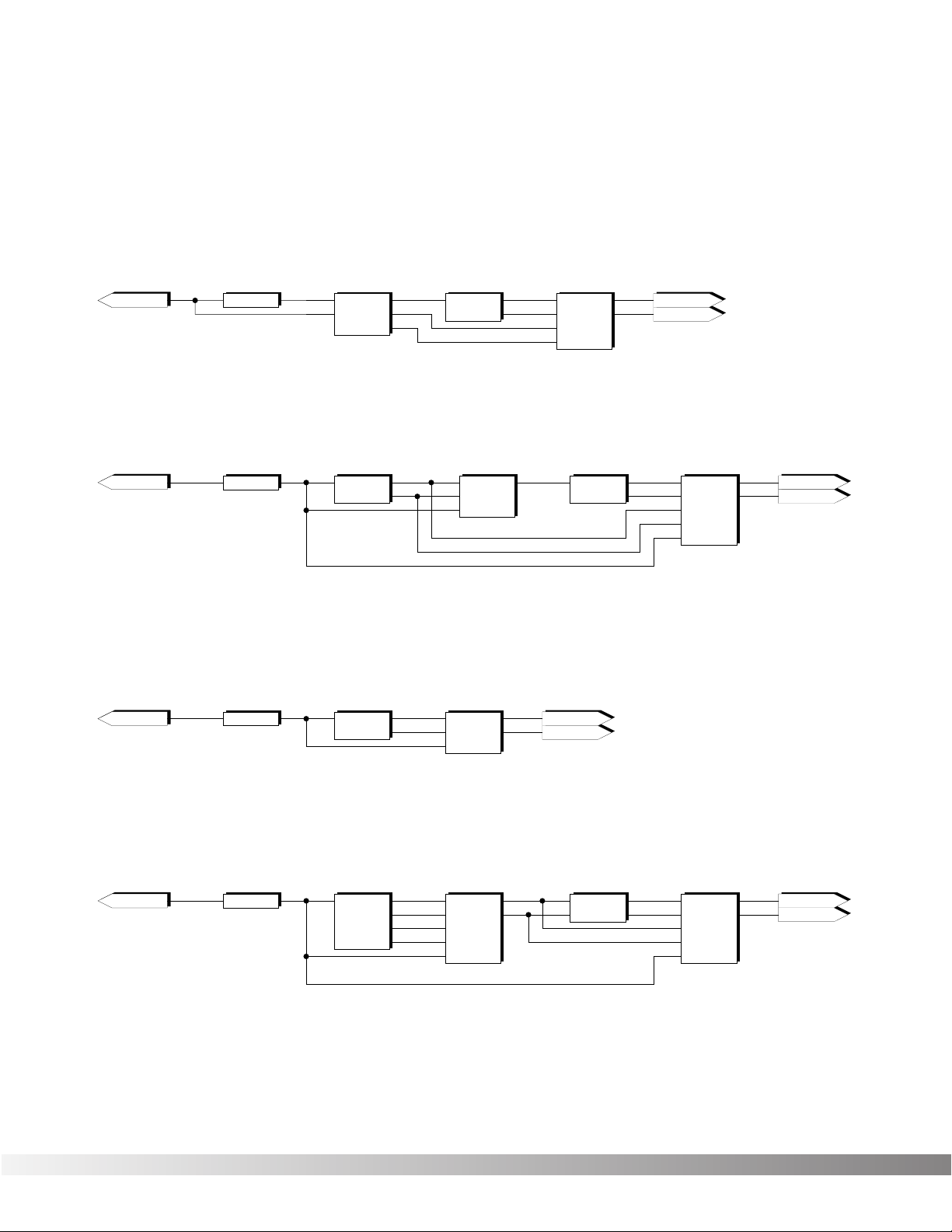
72
LEFT INPUT
Algorithm #14
Mod Dly -> Revrb
LEFT INPUT
Algorithm #15
Wham -> 2TDly -> Revrb
RIGHT MAIN
LEFT MAIN
Out 2
MVRB
MFX Reverb
Inp 1
Out 1
5 x 2
Stereo 5 x 2 Mixer
Out 1
Inp 1
Inp 2
Out 2
Inp 3
Inp 4
Inp 5
In 1
In 2
In 3
In 4
In 5
Out L
Out R
3 x 1
Mono 3 x 1 Mixer
Out 1
Inp 1
Inp 2
Inp 3
Inp 1
Out 1
Wham
Whammy
Inp 1
Out 1
2TDly
2 Tap Delay 8
Out 2
Tap 1
Tap 2
LEFT INPUT
Algorithm #16
Wah -> BigVerb
RIGHT MAIN
LEFT MAIN
LEFT INPUT
Algorithm #17
AWah -> Cho -> Dly
RIGHT MAIN
LEFT MAIN
Inp 1
Out 1
TWah
Traditional Wah
Out 2
BIG
Big Verb
Inp 1
Out 1
3 x 2
Stereo 3 x 2 Mixer
Out 1
Inp 1
Inp 2
Out 2
Out L
Out R
In 1
In 2
Inp 3
In 3
Inp 1
Out 1
AWah
Automatic Wah
5 x 2
Stereo 5 x 2 Mixer
Out 1
Inp 1
Inp 2
Out 2
Inp 3
Inp 4
Inp 5
In 1
In 2
In 3
In 4
In 5
Out L
Out R
4PCho
4-Phase Chorus
Inp 1
Out 2
Out 3
Out 1
Out 4
Cho 2
Cho 3
Cho 1
Cho 4
SDly
Stereo Dly 1.0
Inp 1
Out 1
Inp 2
Out 2
5 x 2
Stereo 5 x 2 Mixer
Out 1
Inp 1
Inp 2
Out 2
Inp 3
Inp 4
Inp 5
In 1
In 2
In 3
In 4
In 5
Out L
Out R
2 x 3
2 x 3 Mixer
Inp 1
Inp 2
In 1
In 2
Out 1
Out 2
Out 1
Out 2
Out 3
Out 3
Inp 1
Out 1
MDly
Modulation Delay
Out 2
MVRB
MFX Reverb
Inp 1
Out 1
4 x 2
Stereo 4 x 2 Mixer
Out 1
Inp 1
Inp 2
Out 2
Out L
Out R
In 1
In 2
Inp 3
In 3
Inp 4
In 4
RIGHT MAIN
LEFT MAIN
Section 6 - Appendix
Valve FX Owner’s Manual
Page 74

73
LEFT INPUT
Algorithm #18
DCho -> 4TDly -> Pan
RIGHT MAIN
LEFT MAIN
5 x 1
Mono 5 x 1 Mixer
Out 1
Inp 1
Inp 2
Inp 3
Inp 5
Inp 4
6 x 2
Stereo 6 x 2 Mixer
Out 1
Inp 1
Inp 2
Out 2
Inp 3
Inp 4
Inp 5
Inp 6
In 1
In 2
In 3
In 4
In 5
In 6
Out L
Out R
4 x 2
Stereo 4 x 2 Mixer
Out 1
Inp 1
Inp 2
Out 2
Out L
Out R
In 1
In 2
Inp 3
In 3
Inp 4
In 4
Inp 1
Out 1
Pan
Auto Panner
Out 2
3 x 3
3 x 3 Mixer
Inp 1
Inp 2
In 1
In 2
Out 1
Out 2
Out 1
Out 2
Out 3
Out 3
Inp 3
In 3
4TDly
4-Tap Delay 1.4
Inp 1
Out 3
Out 4
Out 2
Out 1
Tap 2
Tap 3
Tap 1
Tap 4
LEFT INPUT
Algorithm #19
DDtn -> 4TDly -> Pan
RIGHT MAIN
LEFT MAIN
5 x 1
Mono 5 x 1 Mixer
Out 1
Inp 1
Inp 2
Inp 3
Inp 5
Inp 4
6 x 2
Stereo 6 x 2 Mixer
Out 1
Inp 1
Inp 2
Out 2
Inp 3
Inp 4
Inp 5
Inp 6
In 1
In 2
In 3
In 4
In 5
In 6
Out L
Out R
4 x 2
Stereo 4 x 2 Mixer
Out 1
Inp 1
Inp 2
Out 2
Out L
Out R
In 1
In 2
Inp 3
In 3
Inp 4
In 4
Inp 1
Out 1
Pan
Auto Panner
Out 2
3 x 3
3 x 3 Mixer
Inp 1
Inp 2
In 1
In 2
Out 1
Out 2
Out 1
Out 2
Out 3
Out 3
Inp 3
In 3
4TDly
4-Tap Delay 1.4
Inp 1
Out 3
Out 4
Out 2
Out 1
Tap 2
Tap 3
Tap 1
Tap 4
Inp 1
Out 1
DDtn
Dual Detune
Out 2
Detune 1
Detune 2
DCho
Dual Chorus
Inp 1
Out 1
Out 2
Cho 1
Cho 2
Section 6 - Appendix
Valve FX Owner’s Manual
Page 75

74
LEFT INPUT
Algorithm #20
DFla -> 4TDly -> Pan
RIGHT MAIN
LEFT MAIN
5 x 1
Mono 5 x 1 Mixer
Out 1
Inp 1
Inp 2
Inp 3
Inp 5
Inp 4
6 x 2
Stereo 6 x 2 Mixer
Out 1
Inp 1
Inp 2
Out 2
Inp 3
Inp 4
Inp 5
Inp 6
In 1
In 2
In 3
In 4
In 5
In 6
Out L
Out R
4 x 2
Stereo 4 x 2 Mixer
Out 1
Inp 1
Inp 2
Out 2
Out L
Out R
In 1
In 2
Inp 3
In 3
Inp 4
In 4
Inp 1
Out 1
Pan
Auto Panner
Out 2
3 x 3
3 x 3 Mixer
Inp 1
Inp 2
In 1
In 2
Out 1
Out 2
Out 1
Out 2
Out 3
Out 3
Inp 3
In 3
4TDly
4-Tap Delay 1.4
Inp 1
Out 3
Out 4
Out 2
Out 1
Tap 2
Tap 3
Tap 1
Tap 4
LEFT INPUT
Algorithm #21
DPha -> 4TDly -> Pan
RIGHT MAIN
LEFT MAIN
5 x 1
Mono 5 x 1 Mixer
Out 1
Inp 1
Inp 2
Inp 3
Inp 5
Inp 4
6 x 2
Stereo 6 x 2 Mixer
Out 1
Inp 1
Inp 2
Out 2
Inp 3
Inp 4
Inp 5
Inp 6
In 1
In 2
In 3
In 4
In 5
In 6
Out L
Out R
4 x 2
Stereo 4 x 2 Mixer
Out 1
Inp 1
Inp 2
Out 2
Out L
Out R
In 1
In 2
Inp 3
In 3
Inp 4
In 4
Inp 1
Out 1
Pan
Auto Panner
Out 2
3 x 3
3 x 3 Mixer
Inp 1
Inp 2
In 1
In 2
Out 1
Out 2
Out 1
Out 2
Out 3
Out 3
Inp 3
In 3
4TDly
4-Tap Delay 1.4
Inp 1
Out 3
Out 4
Out 2
Out 1
Tap 2
Tap 3
Tap 1
Tap 4
Out 2
DFla
Dual Flange
Inp 1
Out 1
Out 2
DPha
Dual Phaser
Inp 1
Out 1
Section 6 - Appendix
Valve FX Owner’s Manual
Page 76

75
LEFT INPUT
RIGHT MAIN
LEFT MAIN
Algorithm #22
Gated Reverb
3 x 2
Stereo 3 x 2 Mixer
Out 1
Inp 1
Inp 2
Out 2
Out L
Out R
In 1
In 2
Inp 3
In 3
Inp 1
Out 1
GtRvb
Gated Reverb
Out 2
Left
Right
LEFT INPUT
RIGHT MAIN
LEFT MAIN
Algorithm #23
4PCho -> 2TDly -> SDuc
4PCho
4-Phase Chorus
Inp 1
Out 2
Out 3
Out 1
Out 4
Cho 2
Cho 3
Cho 1
Cho 4
4 x 2
Stereo 4 x 2 Mixer
Out 1
Inp 1
Inp 2
Out 2
Out L
Out R
In 1
In 2
Inp 3
In 3
Inp 4
In 4
5 x 3
5 x 3 Mixer
Inp 1
Inp 2
Inp 3
Inp 4
In 1
In 2
In 3
In 4
Out 1
Out 2
Out 1
Out 2
Out 3
Inp 5
In 5
Inp 1
Out 1
2TDly
2 Tap Delay 1.4
Out 2
Tap 1
Tap 2
SDuc
Stereo Ducker
Out 1
Inp 1
Inp 2
Out 2
Inp 3
LEFT INPUT
RIGHT MAIN
LEFT MAIN
Algorithm #24
Chorus -> BigVerb
4 x 2
Stereo 4 x 2 Mixer
Out 1
Inp 1
Inp 2
Out 2
Out L
Out R
In 1
In 2
Inp 3
In 3
Inp 4
In 4
2 x 3
2 x 3 Mixer
Inp 1
Inp 2
In 1
In 2
Out 1
Out 2
Out 1
Out 2
Out 3
Out 3
Out 2
BIG
Big Verb
Inp 1
Out 1
Cho
Mono Chorus
Inp 1
Out 1
Inp 1
Out 1
Dtn
Mono Detune
LEFT INPUT
RIGHT MAIN
LEFT MAIN
Algorithm #25
Detune -> BigVerb
4 x 2
Stereo 4 x 2 Mixer
Out 1
Inp 1
Inp 2
Out 2
Out L
Out R
In 1
In 2
Inp 3
In 3
Inp 4
In 4
2 x 3
2 x 3 Mixer
Inp 1
Inp 2
In 1
In 2
Out 1
Out 2
Out 1
Out 2
Out 3
Out 3
Out 2
BIG
Big Verb
Inp 1
Out 1
Inp 1
Out 1
Pha
Mono Phaser
LEFT INPUT
LEFT MAIN
Algorithm #27
Phaser -> BigVerb
4 x 2
Stereo 4 x 2 Mixer
Out 1
Inp 1
Out L
In 1
2 x 3
2 x 3 Mixer
Inp 1
In 1
Out 1
Out 1
BIG
Big Verb
Inp 1
Out 1
LEFT INPUT
RIGHT MAIN
LEFT MAIN
Algorithm #26
Flange -> BigVerb
Out 2
BIG
Big Verb
Inp 1
Out 1
Inp 1
Out 1
Fla
Mono Flange
2 x 1
Mono 2 x 1 Mixer
Out 1
Inp 1
Inp 2
3 x 2
Stereo 3 x 2 Mixer
Out 1
Inp 1
Inp 2
Out 2
Out L
Out R
In 1
In 2
Inp 3
In 3
Section 6 - Appendix
Valve FX Owner’s Manual
Page 77

76
LEFT INPUT
RIGHT MAIN
LEFT MAIN
Algorithm #28
Dly -> Dual Chorus
4 x 2
Stereo 4 x 2 Mixer
Out 1
Inp 1
Inp 2
Out 2
Out L
Out R
In 1
In 2
Inp 3
In 3
Inp 4
In 4
Inp 1
Out 1
Dly
Mono Delay 1.0
LEFT INPUT
RIGHT MAIN
LEFT MAIN
Algorithm #29
Dly -> Dual Detune
2 x 1
Mono 2 x 1 Mixer
Out 1
Inp 1
Inp 2
4 x 2
Stereo 4 x 2 Mixer
Out 1
Inp 1
Inp 2
Out 2
Out L
Out R
In 1
In 2
Inp 3
In 3
Inp 4
In 4
Inp 1
Out 1
Dly
Mono Delay 1.0
LEFT INPUT
Algorithm #30
Dly -> Dual Flange
2 x 1
Mono 2 x 1 Mixer
Out 1
Inp 1
Inp 2
4 x 2
Stereo 4 x 2 Mixer
Out 1
Inp 1
Inp 2
Out 2
Out L
Out R
In 1
In 2
Inp 3
In 3
Inp 4
In 4
Inp 1
Out 1
Dly
Mono Delay 1.0
Algorithm #31
Dly -> Dual Phaser
Inp 1
Out 1
DDtn
Dual Detune
Out 2
Detune 1
Detune 2
Out 2
DFla
Dual Flange
Inp 1
Out 1
DCho
Dual Chorus
Inp 1
Out 1
Out 2
Cho 1
Cho 2
2 x 1
Mono 2 x 1 Mixer
Out 1
Inp 1
Inp 2
LEFT INPUT
Inp 1
Out 1
Dly
Mono Delay 1.0
4 x 2
Stereo 4 x 2 Mixer
Out 1
Inp 1
Inp 2
Out 2
Out L
Out R
In 1
In 2
Inp 3
In 3
Inp 4
In 4
2 x 1
Mono 2 x 1 Mixer
Out 1
Inp 1
Inp 2
Out 2
DPha
Dual Phaser
Inp 1
Out 1
RIGHT MAIN
LEFT MAIN
RIGHT MAIN
LEFT MAIN
Section 6 - Appendix
Valve FX Owner’s Manual
Page 78

77
LEFT INPUT
Algorithm #32
Pitch -> 4TDly -> Pan
RIGHT MAIN
LEFT MAIN
4 x 2
Stereo 4 x 2 Mixer
Out 1
Inp 1
Inp 2
Out 2
Out L
Out R
In 1
In 2
Inp 3
In 3
Inp 4
In 4
Inp 1
Out 1
Pan
Auto Panner
Out 2
2 x 1
Mono 2 x 1 Mixer
Out 1
Inp 1
Inp 2
Pch
Mono Pitch Shift
Inp 1
Out 1
LEFT INPUT
Algorithm #34
No Digital
RIGHT MAIN
LEFT MAIN
4TDly
4-Tap Delay 1.4
Inp 1
Out 3
Out 4
Out 2
Out 1
Tap 2
Tap 3
Tap 1
Tap 4
5 x 2
Stereo 5 x 2 Mixer
Out 1
Inp 1
Inp 2
Out 2
Inp 3
Inp 4
Inp 5
In 1
In 2
In 3
In 4
In 5
Out L
Out R
5 x 1
Mono 5 x 1 Mixer
Out 1
Inp 1
Inp 2
Inp 3
Inp 5
Inp 4
Inp 1
Out 1
TWah
Traditional Wah
Cho
Mono Chorus
Inp 1
Out 1
2 x 1
Mono 2 x 1 Mixer
Out 1
Inp 1
Inp 2
Inp 1
Out 1
2TDly8
2 Tap Delay .8
Out 2
Tap 1
Tap 2
4 x 3
4 x 3 Mixer
Inp 1
Inp 2
Inp 3
Inp 4
In 1
In 2
In 3
In 4
Out 1
Out 2
Out 1
Out 2
Out 3
4 x 2
4 x 2 Mixer
Inp 1
Inp 2
Inp 3
Inp 4
In 1
In 2
In 3
In 4
Out 1
Out 2
Out 1
Out 2
RIGHT MAIN
LEFT MAIN
Out 2
MVRB
MFX Reverb
Inp 1
Out 1
LEFT INPUT
Algorithm #33
Wah>Cho>Dly>Rvb
Section 6 - Appendix
Valve FX Owner’s Manual
Page 79

78
BLOCK DIAGRAM Following is a simplified block diagram of the Valve FX.
Section 6 - Appendix
Valve FX Owner’s Manual
Meter
Presence
Distortion
1/4" Output Right
Level
Output
D/A
Converter
1/4" Output Left
Headphone Output
Switch
Bypass
Compressor
Front Panel Input
S-DISC™
A / D
Rear Panel Input
(DSP)
Processor
Converter
Page 80

79
FACTORY PROGRAM LIST
Top Ten
1 O Solo Mio
2 6 Voice Chorus
3 Vintage Amp
4 Virtual Wah
5 Soloing 4ths
6 Whammy Deluxe
7 Chorus Hall
8 Synth Pad Swell
9 True Valve
10 Comfort Zone
Metal Rock
11 Metal Chor/Verbk
12 Grind Your Axe
13 Behemothk
14 Beat on d’ Brat
15 Step It Up
16 Steamroller
17 H.Metal Weekend
18 Ten Foot Screwz
19 Wham Me Down
20 Phase Creep
21 Tube In A Hall
22 Spacey Flange
23 Rude Awakening
24 Sky Dive
25 “Yo, Hollywood”
26 Pedal Pan
27 Face First
28 Stack In A Hall
29 Goin’ Down(Ped)
30 Killer Arena
Pop Clean
31 6 + 6 Makes 12
32 In Full Circle
33 Valve w/Flange
34 Dream Verb
35 Box Of Candles
Pop Rock
36 Wah Kin the Dog
37 Rockin’ Hall
38 L/R Detune
39 Edge Overdrive
40 Power Ballad
41 A Bit Nosey
42 Dynamic Drive
43 Duckerverb
44 Got That Edge
45 Moore Sustain
46 Crunch FX
47 Test Tube Baby!
48 Pop Alternative
49 Crunch Hall Pan
Studio Clean
50 Detune w/Pan
51 Clean X
52 Tap Delays
53 Pan Swirl
54 Delay in Chorus
55 Ultra Chorus
Studio Dirty
56 Thick ‘n Juicy
57 Flying Solo
58 Blue Smoothy
59 A Space Place
60 Your Lef’ Right
61 Touchy Feely
62 Stereo Solo
Mod/Alt Rock
63 Combe Filter Cab
64 Big Bottom
65 Future Shock
66 Wild Phaser
67 Dreamy Flange
68 Bad Apple
69 H.O.T.H.
70 Slappy Rock
Country
71 Pure Country
72 Electric Dobro
73 Tele Funkin’
74 Hawaiian Steel
75 Cowboy Ballad
Harmony
76 Octivizer
77 Take the 5th
78 Tibetan Dream
79 Shim Pedal
80 Pink Rhythm
81 Octave Solo
Jazz
82 Jazzin’
83 Be Bop A Rama
84 Definitely Dry
85 Comp A Little
86 Water Chorus
87 Big House
Classic 70’s
88 Classic Phase
89 British Metal
90 12 String Strum
91 Deep Phase
92 Boxed In
93 Power Rhythm
94 Smooth Change
95 Talk Box
Blues
96 Cleanest Blue
97 Club Rat
98 Leslie Pedal
99 Super Duck
100 Pannin’ For Blue
101 Cool Combo
Modern Jazz
102 Mellow Lead
103 Pedal Of Life
104 Synthy Solo
105 Infusion
106 Techno Crunch
107 Mod World
New Age
108 Pedal Synth
109 6 String Chime
110 Envelope Pan
111 Guitar Pad
112 New Ageless
113 Borealis
114 Guitar Synth
50’s and 60’s
115 Surf’s Up
116 60’s Wah Wah
117 Vari-Trem
118 Doppler Flange
119 Happy Hippy
120 Wahs Dat Pedal?
121 Fuzz Tremelo
122 Saving Phase
Special Application
123 Pipe Organ
124 Wait A Second
125 1.5 Sec Sampler
126 Sound on Sound
127 Phase To Trem
128 Clean and Empty
Section 6 - Appendix
Valve FX Owner’s Manual
Page 81

80
Basic
Channel
Default
Channel
1-16
1-16
Mode 3
X
X
Mode 3
X
X
XX
XX
XX
XX
XX
XX
XX
XX
XX
XX
XX
XX
XX
XX
XO
OO
OO
1-16
0-127
0-127 1-128
1-16
Default
Messages
Altered
True Voice
Note
Number
Mode
Velocity Note ON
Note OFF
Function... Transmitted Recognized Remarks
After
Touch
Key's
Ch's
Pitch Bender
Control
Change
Prog
Change
True #
System Exclusive
System
Common
:Song Pos
:Song Sel
:Tune
System
Real Time
:Clock
:Commands
Aux
Messages
:Local ON/OFF
:All Notes Off
:Active Sense
:Reset
Notes
Mode 1 : OMNI ON, POLY Mode 2 : OMNI ON, MONO
Mode 3 : OMNI OFF, POLY Mode 4 : OMNI OFF, MONO
O : Yes
X : No
Memorized
Default Channel 1
Section 6 - Appendix
Valve FX Owner’s Manual
Page 82

8760 South Sandy Parkway
Sandy, Utah, 84070
Telephone (801) 566-8800
FAX (801) 566-7005
International Distribution: 7 Farmington Road
Amherst, New Hampshire 03031 U.S.A.
FAX (603) 672-4246
DigiTech™, S-DISC™, Whammy™ and Silencer™
are registered trademarks of DOD Electronics
Corporation
Copyright © 1994
DOD Electronics Corporation
Printed In U.S.A. 9/94
Manufactured in the U.S.A.
Valve FX 18-2098
OS v1.00
EFFECTS ACCESSURSOR DATA
S-DISC
™
P
ROCESSING
Bypass
Midi/Util
Name
EQ
More
Chorus
Mix
Sample
Delay
Pitch
Reverb
Mod
321
E
This manual
is made from
recycled
materials.
 Loading...