

Page 1

SD10 Operation Manual
User Manual
User Manual Version A for Software Versions 1.0.415+
0-1
Page 2

SD10 Operation Manual
Copyright © 2011 Digico UK Ltd
All rights reserved.
No part of this publication may be reproduced, transmitted, transcribed, stored in a retrieval system, or translated into any
language in any form by any means without the written permission of Digico UK Ltd. Information in this manual is subject to
change without notice, and does not represent a commitment on the part of the vendor. Digico UK Ltd shall not be liable for any
loss or damage whatsoever arising from the use of information or any error contained in this manual.
All repair and service of the SD10 product should be undertaken by Digico UK Ltd or its authorised agents. Digico UK Ltd cannot
accept any liability whatsoever for any loss or damage caused by service, maintenance, or repair by unauthorised personnel.
Software License Notice
Your license agreement with Digico UK Ltd, which is included with the SD10 product, specifies the permitted and prohibited uses
of the product. Any unauthorised duplication or use of Digico UK Ltd software, in whole or in part, in print or in any other storage
and retrieval system is prohibited.
Licenses and Trademarks
The SD10 logo and SD10 name are trademarks, and Digico UK Ltd and the Digico UK Ltd logo are registered trademarks of Digico
UK Ltd. Microsoft is a registered trademark and Windows is a trademark of Microsoft Corp.
Digico (UK) Ltd
Unit 10
Silverglade Business Park
Leatherhead Road
Chessington
Surrey
KT9 2QL
England
Telephone: +44 (0)1372 845600
Fax: +44 (0)1372 845656
Email: sales@digiconsoles.com
WWW: http://www.digiconsoles.com
Manual Issue and Date: Issue A - March 2011 - For Version 1.0.415+ Software
Licence Agreement
"Product" : SD10 software product produced by Digico UK Ltd intended for use on Target Platform identified below.
"Target Platform": Digico SD10 Digital Console system.
In return for the payment of the one-time fee, the Customer (identified at the end of this Agreement) receives from Digico UK
Ltd a licence to use the Product subject to the following terms and conditions.
1. The Product may be used without time limit by the Customer on the Target Platform.
2. The Customer must register the Product with Digico UK Ltd. Registering the Product is deemed an acceptance of the terms and
conditions in this agreement.
3. The Product and its licence are not transferable, and the Customer is not permitted to onward-license to any third party. The Customer indemnifies Digico UK Ltd against any and all claims and actions arising from third party use of copies of the Product made by
the Customer.
4. The Customer agrees not to attempt to decompile the object code of the Product otherwise than in circumstances specifically provided
for by law, and then only after consultation with Digico UK Ltd.
5. The Customer agrees not to use, or licence the Product for use, with equipment other than the Target Platform.
6. The Customer agrees not to modify the Product without the prior written consent of Digico UK Ltd.
7. This Agreement applies to any enhancement or upgrades that may become available for the Product.
8. This Agreement does not transfer any right, title, or interest in the Product to Customer except as specifically set forth herein.
9. Digico UK Ltd reserves the right to terminate this Agreement upon breach, in which event Customer shall thereafter only be authorised
to use the Product to the extent that its contractual commitments to third parties require and then only where such commitments relate
to use of the Product as authorised in the foregoing provisions of the Agreement.
LIMITED WARRANTY - Digico UK Ltd warrants for a period of 1 year from the date of purchase of the Product, the Product will reasonably execute its programming instructions when properly installed on the Target Platform. In the event that this Product fails to execute its
programming instructions during the warranty period, the Customer's remedy shall be to return the Product to Digico UK Ltd for replacement or repair at Digico UK Ltd option. Digico UK Ltd makes no other express warranty, whether written or oral with respect of this
Product.
LIMITATION OF LIABILITY - Except as otherwise expressly provided by law, (a) the remedies provided above are the Customer's sole
and exclusive remedies and (b) Digico UK Ltd shall not be liable for any direct, indirect, special, incidental, or consequential damages
(including lost profit whether based on warranty, contract, tort, or any other legal theory.)
This agreement is made under the Laws of England.
LICENCE NO:..................... ..........................................................
REGISTRATION DATE: ..... ..........................................................
0-2
Page 3

SD10 Operation Manual
Contents
1.1 Introduction .............................................................................. .......1-3
1.2 Manual Overview ..................................................................... .......1-3
1.3 Before You Start..............................................................................1-4
1.3.1 Worksurface Layout .............................................................1-4
1.3.2 Screen Assignment ..............................................................1-5
1.3.3 Layers and Banks.................................................................1-6
1.3.4 Using the Control Surface ...................................................1-6
1.3.5 The Assigned Channel.........................................................1-7
1.3.6 The Master Fader ..................................................................1-7
1.3.7 Other Centre Section Controls ............................................1-8
1.3.8 Channel Types ......................................................................1-8
1.4 Hardware Configuration.......................................................... .......1-9
1.4.1 Connections..........................................................................1-9
1.4.2 Audio I/O Panel....................................................................1-10
1.5 Configuring a Session .......................................................... .......1-13
1.5.1 Session Structure ...............................................................1-13
1.5.2 Assigning Faders to the Worksurface....................... .......1-14
1.6 Saving and Loading Sessions ............................................. .......1-15
1.7 Audio Sync .............................................................................. .......1-16
1.8 Routing Basics ....................................................................... .......1-17
1.8.1 Selecting Inputs & Outputs ................................................1-17
1.8.2 Ripple Channels .................................................................1-18
1.9 Presets..................................................................................... .......1-19
1.10 Naming Channels and Busses........................................... .......1-20
1.11 Channel Processing ............................................................ .......1-21
1.11.1 EQ.......................................................................................1-21
1.11.2 Dynamics...........................................................................1-22
1.11.3 Auxiliaries ..........................................................................1-22
1.12 The Matrix ............................................................................. .......1-23
1.13 Control Groups .................................................................... .......1-24
1.14 Solo Setup............................................................................. .......1-25
0-3
Page 4

SD10 Operation Manual
2.1 Introduction to Channel Types .............................................. .......2-2
2.2 Channel Input Setup - Common Elements ........................... .......2-2
2.2.1 Channel Strip Input Area ......................................................2-2
2.2.2 Channel Names ....................................................................2-2
2.2.3 Channel Safes.......................................................................2-3
2.2.4 Channel Settings ..................................................................2-3
2.2.5 Channel Solos ......................................................................2-5
2.3 Channel Output and Inserts - Common Elements ............... .......2-6
2.3.1 Channel Strip Output Area ...................................................2-6
2.3.2 Channel Strip Insert Areas ............................................ .......2-7
2.3.3 Console Output and Insert Routing ....................................2-7
2.3.4 Creating and Configuring FX Modules ...............................2-7
2.4 Input Channel Specific Functions ....................................... .......2-10
2.4.1 T rim and Track ....................................................................2-10
2.4.2 Input Routing ......................................................................2-10
2.4.3 Input Configuration ............................................................2-10
2.4.4 Output Routing ............................................................ .......2-11
2.4.5 Aux Busses and Assignable Controls ....................... .......2-11
2.4.6 Group Outputs ....................................................................2-12
2.4.7 Direct Outputs .....................................................................2-12
2.5 Group Channels Specific Functions ..........................................2-13
2.6 Aux Channels Specific Functions ..............................................2-13
2.7 Matrix Channels Specific Functions ................................... .......2-14
2.8 Channel Signal Processing .................................................. .......2-14
2.8.1 Channel Filters (Input Channels Only) ..............................2-14
2.8.2 Channel EQ .........................................................................2-14
2.8.3 Channel Dynamics .............................................................2-16
2.9 LCD Functions........................................................................ .......2-17
2.9.1 Introduction to LCD Functions..........................................2-17
0-4
2.9.2 Solo......................................................................................2-17
2.9.3 Solo Choice.........................................................................2-17
2.9.4 GANG ...................................................................................2-17
2.9.5 JOIN CG ...............................................................................2-18
2.9.6 Assign Faders .....................................................................2-19
2.9.6 Unassign Faders ................................................................2-19
2.9.8 Copy Bank From.................................................................2-20
2.9.9 Copy Bank To .....................................................................2-20
2.9.10 Clear Bank.........................................................................2-20
Page 5

SD10 Operation Manual
3.1 System Menu ............................................................................ .......3-2
3.1.1 Diagnostics ...........................................................................3-2
3.1.2 Oscillator ...............................................................................3-2
3.1.3 Security .................................................................................3-2
3.1.4 Clear Over Indicators............................................................3-4
3.1.5 Overview Clear Screen.........................................................3-4
3.1.6 Keyboard Help ......................................................................3-4
3.1.7 F10: Reset FX........................................................................3-4
3.1.8 F11: Reset Engine ................................................................3-4
3.1.9 F12: Reset Surfaces .............................................................3-4
3.1.10 Set Date & Time ..................................................................3-4
3.1.11 Shutdown ............................................................................3-4
3.2 Files Menu ................................................................................. .......3-5
3.2.1 Session Structure .................................................................3-5
3.2.2 Load Session ........................................................................3-7
3.2.3 Save Session ........................................................................3-7
3.2.4 Save As New File ..................................................................3-7
3.2.5 Load Presets .........................................................................3-8
3.2.6 Save Presets .........................................................................3-9
3.2.7 Global Set T o Defaults..........................................................3-9
3.2.8 Session Notes.....................................................................3-10
3.2.9 Session Report ...................................................................3-10
3.3 Layout Menu ........................................................................... .......3-11
3.3.1 Fader Banks................................................................. .......3-11
3.3.2 Channel List ........................................................................3-12
3.3.3 T ransport Control ...............................................................3-12
3.4 Snapshots Menu .................................................................... .......3-13
3.4.1 Storing a Snapshot.............................................................3-13
3.4.2 Recalling a Snapshot .........................................................3-14
3.4.3 Replacing a Snapshot ........................................................3-14
3.4.4 Editing Multiple Snapshots ................................................3-14
3.4.5 Moving a Snapshot.............................................................3-15
3.4.6 Renaming a Snapshot........................................................3-15
3.4.7 Renumbering Snapshots...................................................3-15
3.4.8 Deleting a Snapshot ...........................................................3-15
3.4.9 Snapshot Undo...................................................................3-15
3.4.10 Snapshot Groups .............................................................3-15
3.5.11 Global Recall Scope.........................................................3-17
3.5.12 Individual Snapshot Recall Scope .................................3-17
3.5.13 Snapshot Crossfades ......................................................3-18
0-5
Page 6

SD10 Operation Manual
3.5.14 Snapshot Recall Times ....................................................3-19
3.5.15 Introducing Snapshots and MIDI.....................................3-19
3.5.16 Snapshot Control by MIDI ................................................3-19
3.4.17 MIDI Devices......................................................................3-20
3.4.18 MIDI Program and MIDI List..............................................3-20
3.4.19 GPOs and Snapshots.......................................................3-21
3.4.20 Surface Offline & Snapshot Editing ................................3-22
3.4.21 Snapshot s and Transport Automation............................3-22
3.4.22 Auto Update ......................................................................3-22
3.5 Options Menu ................................................................................3-23
3.5.1 Surface ................................................................................3-23
3.5.2 Faders..................................................................................3-24
3.5.3 Solo......................................................................................3-24
3.5.4 Disable.................................................................................3-25
3.5.5 Brightness...........................................................................3-25
3.5.6 Meters ..................................................................................3-25
3.5.7 Session................................................................................3-26
3.5.8 Status...................................................................................3-26
3.6 Matrix Menu.......3-28
3.6.1 The Matrix Panel .................................................................3-28
3.6.2 Matrix Presets .....................................................................3-29
3.7 Graphic EQs Menu ................................................................ .......3-29
3.7.1 Graphic EQ Panel................................................................3-29
3.7.2 Ganging Graphic EQs.........................................................3-30
3.7.3 Graphic EQ ALL Button......................................................3-30
3.7.4 Graphic EQ Presets ............................................................3-30
3.8 Solos Menu ............................................................................. .......3-31
3.8.1 The Solo Panel....................................................................3-31
3.8.2 The No Solo Setup Display ................................................3-32
3.8.3 Assigning Solo Busses to W orksurface Controls ...........3-33
3.8.4 Solo Outputs Routing................................................. .......3-33
3.8.5 Headphone Outputs ...........................................................3-33
3.9 Setup Menu ....................................................................................3-34
3.9.1 Audio I/O ..............................................................................3-34
3.9.2 Port Selection......................................................................3-34
3.9.3 Port Hardware Configuration.............................................3-34
3.9.4 Port Control.........................................................................3-35
3.9.5 The Socket Display.............................................................3-35
3.9.6 Socket Conforming ............................................................3-35
0-6
Page 7

SD10 Operation Manual
3.9.7 Group and Socket Names ..................................................3-36
3.9.8 Socket Options ...................................................................3-36
3.9.9 Audio Sync ..........................................................................3-36
3.9.10 Timecode & T ransport......................................................3-37
3.9.11 Macros ...............................................................................3-37
3.9.12 The Macro Editor ..............................................................3-38
3.9.13 T alkback ............................................................................3-39
3.10 Screen and Light Brightness ............................................. .......3-40
4.1 Network and Mirroring ............................................................ .......4-2
4.1.1 Network Configuration.........................................................4-2
4.1.2 Mirroring for the first time.....................................................4-2
4.2 Multi-console Setups ......................................................................4-4
4.2.1 FOH and Monitors sharing a stage rack .............................4-4
5.1 Troubleshooting ...................................................................... .......5-2
5.1.1 Starting the console .............................................................5-2
5.1.2 Audio not p assing on cert ain channels ..............................5-2
5.1.3 Snapshots not recalling as expected..................................5-2
5.1.4 Snapshots not inserting as expected .................................5-2
5.1.5 Assigning console controls .................................................5-2
5.1.6 Console controls not affecting the audio ...........................5-2
5.1.7 Channels not appearing on the worksurface.....................5-3
5.1.8 No signal from the Solo buss ..............................................5-3
5.1.9 Signal from the Solo buss when nothing is soloed ...........5-3
5.1.10 External keyboard ..............................................................5-3
5.1.11 Resetting the console.........................................................5-3
5.1.12 T alkback ..............................................................................5-3
5.1.13 Meters ..................................................................................5-3
5.1.14 Console lighting..................................................................5-3
5.1.15 Joystick not responding as expected...............................5-3
5.1.16 Features not yet implemented ...........................................5-3
5.1.17 Diagnostics .........................................................................5-4
0-7
Page 8

SD10 Operation Manual
0-8
Page 9

Chapter 1 - Getting Started
SD10 Operation Manual
Chapter 1:
Getting Started
1-1
Page 10

Chapter 1 - Getting Started
1-2
Page 11
Chapter 1 - Getting Started
1.1 Introduction
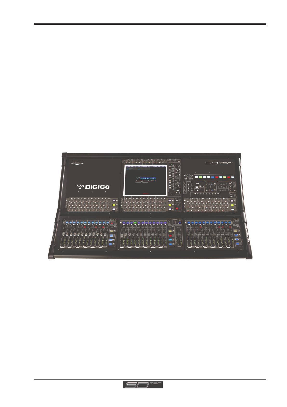
The Digico SD10 consists of a worksurface with an onboard audio engine and a range of onboard inputs and outputs. This can be
connected to multiple Input/Output Rack Units by MADI links or optical fibre (optionally) which carry all the audio input and output
signals.
The console worksurface consists of 3 sections that can control 96 input channels (12 of which can be stereo with no loss of
channel count), 12 VCAs, up to 48 aux/group busses (plus Master buss configurable as LCR, and solo buss), a matrix of 16
inputs and 12 outputs, 24 onboard graphic EQs and 10 onboard stereo effects.
The left section has 12 assignable faders and 12 sets of assignable encoders and switches.
The centre section has, a touchscreen, 12 assigned encoders, 12 assignable faders, 12 sets of assignable encoders and
switches, a full set of channel processing controls and a master fader.
The right section has 12 assignable faders, 12 sets of assignable encoders and switches and controls for monitoring, head-
phones, talkback, macros and snapshots.
Any of these worksurface sections can be assigned to the centre touchscreen.
Multiple console setups can provide:
Front of House and Monitoring with shared stage racks and gain tracking.
Remote control of a console from a laptop computer.
Optional extras include Waves plug-ins and Broadcast mode (Broadcast mode includes features such as surround busses, mix
minus busses, multi-input channels, backstop PFL, auto PFL, fader start GPOs and expanded monitoring options). See the Appendices for details of these options.
1.2 Manual Overview
- Chapter 1 provides an overview of the desk, and describes some of the basic operating principles which the user
will need to understand in order to run the desk.
- Chapter 2 describes the functions of the different channel types.
- Chapter 3 describes the master section of the desk, focusing on the various menus in the Master screen.
- Chapter 4 describes network, mirroring and multi-console setups
- Chapter 5 is a guide to troubleshooting
- Appendices are provided for the Waves plug-ins, Broadcast mode options, and Optocore operation.
The following typographical conventions are used in this manual:
Bold type is used to indicate that the text is an exact copy of the labelling either on a screen or on the worksurface.
An arrow bracket (>) is used to indicate a sequence of button pressing. For example, Layout > Fader Banks indicates that the
Fader Banks button is accessed by first pressing the Layout button.
1-3
Page 12
Chapter 1 - Getting Started
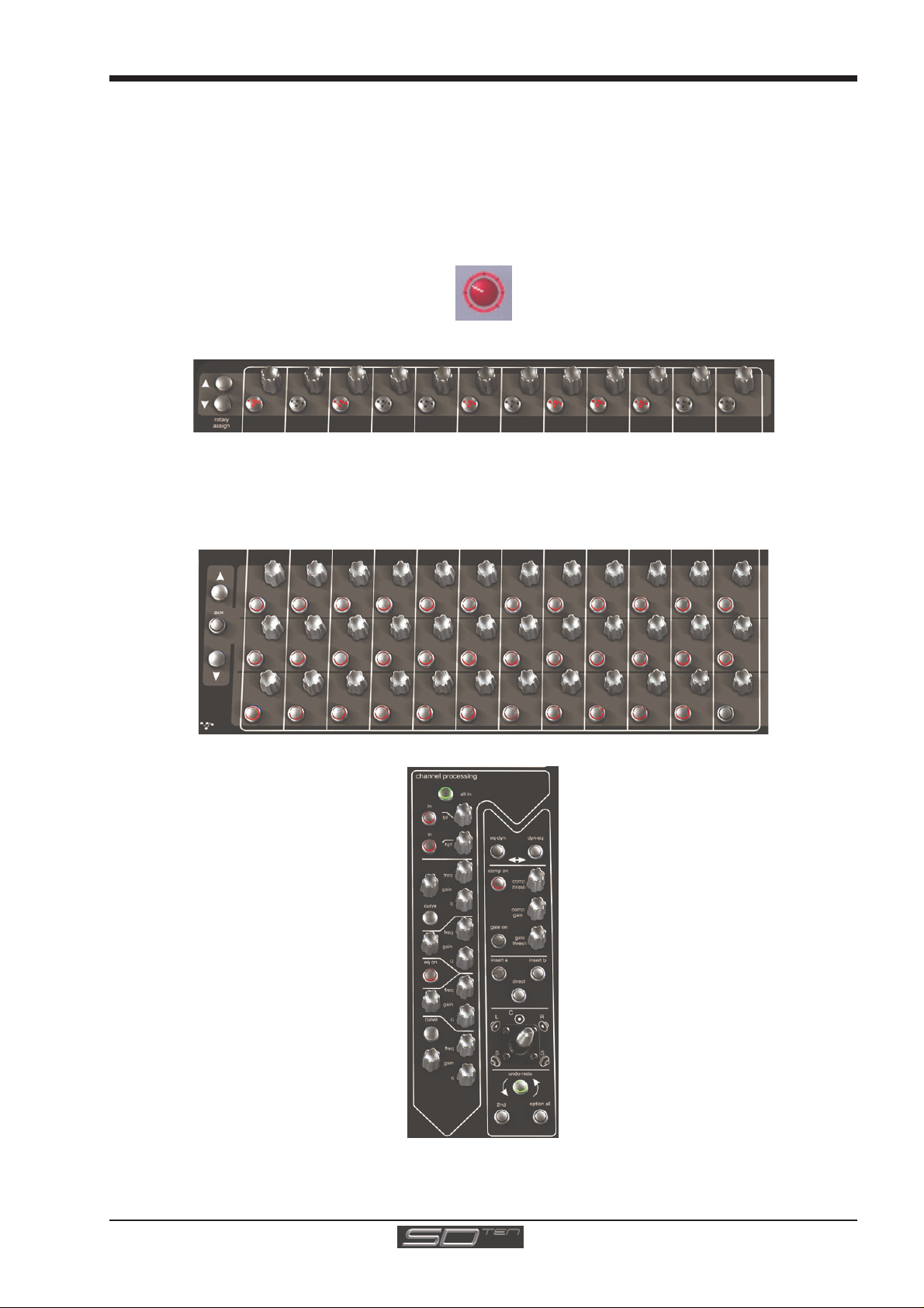
A
A
USB Port
Light
Assignable Rotary Scrollers
Dynamics Thresholds & On / Off
n
A
n
1.3 Before You Start
There are certain general operating principles and terms that should be understood before continuing to use this manual.
Please read this chapter carefully before proceeding.
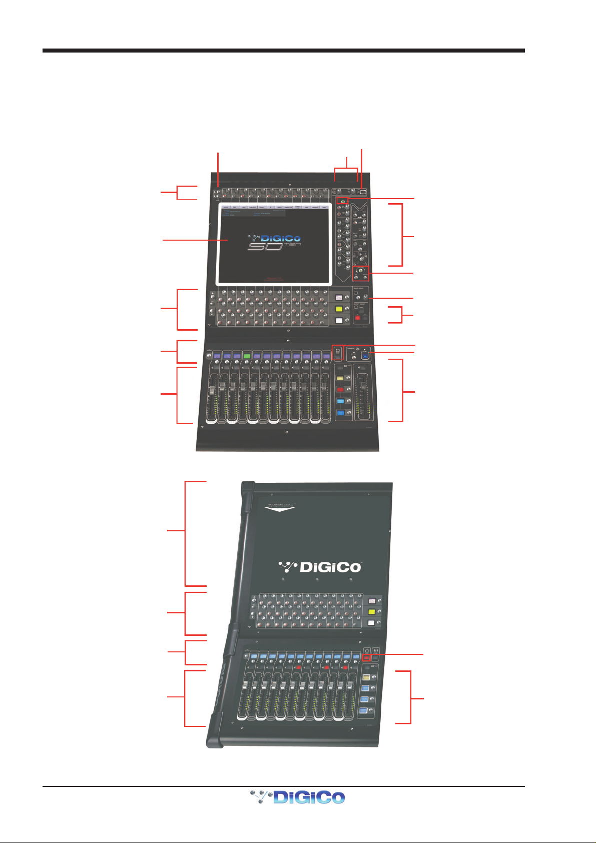
1.3.1 Worksurface Layout..............................................................
Centre Section
Controls
Input Gain and Phase
Touchscreen
ssignable Rot aries and Switches
ux / Pan / Dynamics/FX Controls
Mute and Channel Select Buttons
Channel Faders
Left Section
ALT Input Sw i t ch
Channel Processing:
High and Low Pass Filters
4 Band Dynamic Parametric EQ
Channel Inserts A & B On/Off
Direct Out On/Off
Joystick Panning
Undo/Redo
2nd Function Button
Option/All Button
Touch/Turn Controls
Left/Right/Master Screen Assig
Centre Section Sc reen Assign
Snapshot Previous / Next
Bank Select Buttons
& Master Fader/ Mu te
Laptop Area for Optional
Remote Control
ssignable Rotaries and Switches
Aux / Pan / Dyna mics Controls
Mute and Channel Select Buttons
Channel Faders
Left Section Screen Assig
Bank Select Buttons
1-4
Page 13
Right Section
A
n
Chapter 1 - Getting Started
Space for Keyboard
& Trackball
Smart Keys
Snapshot Automa tion
Macros
ssignable Rotaries and Switches
Aux / Pan / Dynamics Controls
Mute and Channel Select Buttons
Channel Faders
Monitoring
Talk back
Right Section Screen Assig
Bank Select Buttons
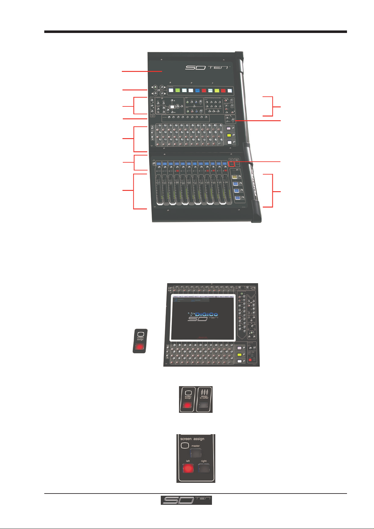
1.3.2 Screen Assignment...............................................................
The SD10 touchscreen is used to access many of the console's functions. There are 4 possible views that can be seen on this screen - Left section - Centre section - Right section - Master screen Each console worksurface section has its own Screen Assign button which, when pressed, will allow the channels in that
section to be viewed on the screen and controlled by the Centre section's Channel Processing controls such as EQ and Dynamics. When the button is lit, that section is assigned to the screen.
When a section has been assigned to the screen all of the controls in the upper centre section are also assigned.
The Left and Right worksurface sections also each have a button labelled Assign To Centre which will allow all of the Centre sections controls including faders, mutes and solos to control the bank which has been selected in the Left or Right sections..
There are also additional buttons in the centre section which can assign the Left and Right sections to the screen and a Master
button which allows you to view the Master screen. The Master screen gives access to many setup and other functions which
are not directly related to the console's channels.
1-5
Page 14
Chapter 1 - Getting Started
S
S
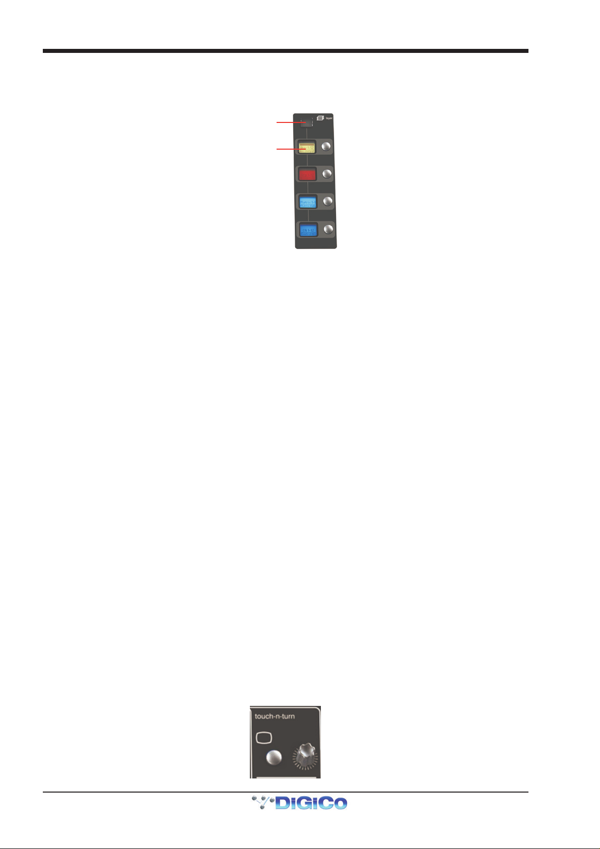
1.3.3 Layers and Banks .................................................................
The SD10's worksurface is divided into Layers and Banks. Each Bank contains twelve channels, and the channels which are
currently active on the control surface are defined using the fader bank and bank layer buttons to the right of the Channel Strip
section’s faders:
elect a Layer
elect a Bank
A ‘bank’ is a set of twelve faders, and a ‘layer’ contains up to four ‘banks’. There are two ‘layers’ in each section of the desk,
allowing up to 144 channels to be accessible on the worksurface.
Pressing the bank layer button, located above the fader bank buttons, toggles between layers.
To access a bank of faders within that layer, press the appropriate fader bank button. To switch all three sections of the
console to the same bank level, press and hold one of the fader bank buttons.
The position of the banks on the worksurface is defined in the Layout > Fader Banks panel. By default, the Input channels will
be assigned to Layer 1 on the left and right sections of the console. The different output channels will be assigned to Layer 1 on
centre section. Control Groups will also be assigned to the centre section. These bank assignments can be customised by the
user and saved in a session at any time.
1.3.4 Using the Control Surface ....................................................
There are two main ways in which all of the functions of the SD10 are accessed:
1. The touchscreen display, which can be controlled directly using a finger, or by using the keyboard and mouse
2. The physical encoders, switches and faders.
Note that when touching the screen directly, you may find it easier to use a finer point than your finger.
However, in order to prevent damage to the screen, it is important that you only use devices specifically
designed for touching screens (such as a pda stylus), and that you never press down hard on the screen.
A number of functions can be accessed in different ways, allowing users to operate the console using whichever interface they
prefer. This manual will describe accessing on-screen functions by touching the screen directly and not by using the mouse.
All of the physical controls found in the centre section are described in full within the relevant section of the manual and many
require no further introduction. The Master screen has a row of grey buttons which are used to access a range of configuration
displays. Pressing these buttons opens either a further drop-down sub-menu or a pop-up display. If a drop-down menu is
opened, pressing on one of its entries will open a pop-up display. The buttons lighten to indicate that their sub-menu or pop-up
display is open. A number of the buttons within each pop-up display generate further pop-ups.
The buttons within the pop-ups are coloured grey when their function is inactive, generally switching to a lighter shade of the
pop-up background when their function is active. Pressing on a text box opens a numeric or QWERTY keypad which can be
operated directly by pressing the screen or via the console’s external keyboard.
Pop-ups are closed by pressing the box in the top right-hand corner of the pop-up, marked CLOSE or CANCEL (or by pressing CAN on keypad pop-ups).
To the right and below the Master screen is a single encoder marked touch-n-turn (shown below). This is used to access some
of the rotary and switch controls within the Master screen. To assign the touch-n-turn encoder to a particular on-screen pot,
touch the pot to be assigned. You will notice that a coloured ring appears around the on-screen pot, indicating that it is assigned
to the touch-n-turn encoder/switch.
1-6
Page 15
Chapter 1 - Getting Started
1.3.5 The Assigned Channel .........................................................
One of the channels in the Channel Strip panel is displayed in gold, indicating that it is currently the Assigned Channel. This means
that it has been assigned to the worksurface controls and can be configured in detail, as described below. To Assign a channel,
touch anywhere in the channel on the screen (except the Aux Send area).
Once a channel is Assigned, all of the controls for that channel which are not displayed within the channel strip itself can be
accessed via secondary pop-ups, displayed by touching inside the relevant area of the channel. These pop-ups include controls
such as input and output routing and signal processing parameters.
A number of the physical rotary encoders on the control surface can be assigned to different on-screen pots. In order to ensure
that it is clear which function is assigned to which encoder, the assigned on-screen pot will have a coloured ring around it.
The twelve encoders and buttons immediately above the touchscreen refer to the channels with which they are aligned. These
controls are concerned with the channel input, located at the top of the Channel Strip panel.
The three rows of encoders and buttons immediately below the touchscreen also refer to the channels with which they are
aligned. Normally, the upper two rows control the level and on/off status of the two highlighted aux sends, but can have a number
of functions assigned to them. Touching on an aux send on the screen will assign that aux and the ones immediately below it to
the aux encoders. Six of the aux sends can be displayed in the Channel Strip panel at any one time. If more than six aux sends
have been created in the session, the scroll buttons outside the bottom left-hand corner of the screen can be used to scroll the
display through the remaining auxiliaries. The third row is assigned to channel pan by default.
The controls to the right of the Channel Strip panel allow the Assigned channel to be adjusted:
1.3.6 The Master Fader..................................................................
By default, the master fader is assigned to the master group output, which is the lowest stereo group output by default. In
addition, the master fader can be assigned to the solo buss output.
1-7
Page 16
Chapter 1 - Getting Started
Inputs
C
Groups
Auxes
Matrix
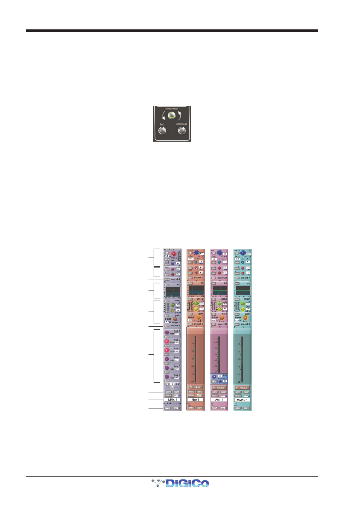
1.3.7 Other Centre Section Controls.............................................
To the left of the Channel Strip panel are more channel controls: When pressed, the 2nd function button allows access to different parameters:
1) Stereo Aux Pan and Pre/Post switching
2) Hard Mute of a channel
3) Fine adjustment of Delay settings on output channels
The Option/All button has 2 main functions:
1) When pressed and released, any channel that is a member of a gang will be temporarily isolated from that gang.
2) When pressed and held, any parameter that is adjusted on a single channel will also be adjusted in the same way
on all of the channels in that bank
1.3.8 Channel Types ......................................................................
The signal flow of the SD10 is best understood in terms of the four channel types contained within it, shown below. Each channel
type offers full signal processing capabilities. As a summary, the four channel types are as follows:
- Input channels bring signals into the console to be mixed and sent to aux and group busses.
- Aux channels send a variety of mixes of the Input channels to the Aux outputs, mainly for use as monitor mixes and FX
sends.
- Group channels mix groups of input channels together, to feed the buss outputs or the output matrix.
- Matrix channels send the outputs of the matrix to the console’s main outputs (Optionally).
Note there is also a TB In channel which is its own channel type. This is described in the Talkback section of the Master
Screen chapter.
The Group channels, Aux channels and Matrix channels are all referred to as output channels. While the Aux and Matrix channels
are the channel types most commonly routed to outputs, all four channel types can be routed directly to outputs.
Input Module - Touch to Expand
Analogue Gain/ Digi tal Trim
Phase - Gain Track i ng
Main/Alt Input Select
HPF/LPF
Inser t A Rout ing & On/Off
4 Band EQ
Touch To Expand
Dynamics
Touch To Expand
Insert B Routing & On/Off
Aux Se nds (
omponent unf olding (Group, Aux)
Routing Module - Touch to Expand
Input Channels -
Touc h to Assign Rows
Metering (Output Channels)
Talkback (Aux)
Channel Pan
Mute & Hard Mu te
Channel Label
Gang & Safe Indicators
)
Channels are laid out in banks of 12 on the console worksurface and can be identified by their colour: Light-blue for Input channels, red for Group channels, purple for Aux channels and blue-green for Matrix channels.
By default, the Input Channels will be assigned to Layer 1 on the left and right sections of the console. Output channels (Groups,
Auxes and Matrices) and Control Groups will be assigned to the centre section. These bank assignments can be customised by
the user and saved in a session at any time.
Holding any bank or layer button down for a couple of seconds will switch all 3 worksurface sections to the same bank level or
layer.
The controls on each different type of output channel are similar but an input channel has a number of additional features.
1-8
Page 17
Chapter 1 - Getting Started
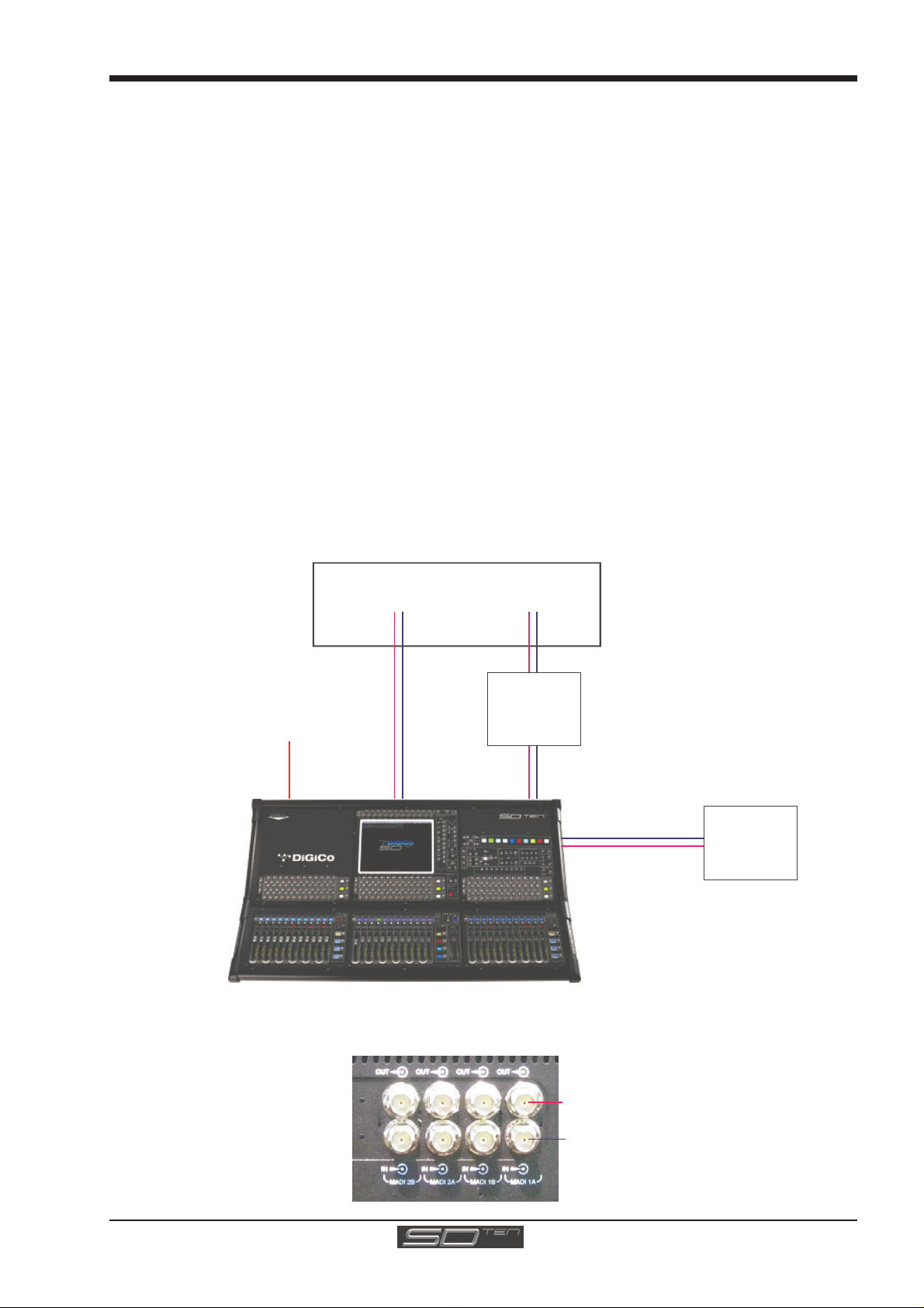
E
STANDARD CONN E CTION WI TH MADI
Redundant
r
k
1.4 Hardware Configuration
1.4.1 Connections ..........................................................................
Detailed information on the various systems of connection is provided in the relevant Appendix but the following diagram provides
an overview of a single console/single rack setup.
All connections should be made before switching on the console and racks.
The console and rack each have dual redundant power supplies and both should be switched on at all times. After switching on
the console the software will be launched automatically and the state of the worksurface and settings should be the same as
when it was last Shut Down.
To Shut Down the console press the System>Shut Down button and wait until you receive a message saying that it is safe to
switch the power off.
The SD10 worksurface has 8 analogue I/O and 8 AES I/O on its rear panel and remote I/O racks are available in several formats.
These racks can be connected to the console with 2x 100M high specification 75Ohm coaxial cables fitted with BNC connectors,
or optical fibre.
In normal operation the MADI connections should be as follows (see diagram below):
Rack MAIN MADI IN connected to the console MADI 1A OUT
Rack MAIN MADI OUT connected to the console MADI 1A IN
Note - Optionally, a second set of MADI cables can be connected to provide MADI redundancy from the
rack's AUX MADI ports to the console's MADI 1B ports
The console's MADI Port 2 can be connected to a MADI recorder or a second DiGiCo Rack or console.
Remote I/O Rack
MAIN MADI
IN
Optional Remote Control
Laptop connection with
thernet Crossover Cable
MADI 1A OUT
SD10 Rear Panel MADI Connec tions
MAIN MADI
OUT
MADI 1A IN
AUX MADI
IN
MADI 1B OUT
MADI 1BMADI 2AMADI 2B
AUX MADI
Optional
MADI
Connection
MADI 1B IN
MADI 1A
OUT
MADI 2A IN
MADI 2B OUT
MADI OUT
MADI IN
Optional
MADI Recorde
or
Second I/O Rac
MADI OUTPUTS
MADI INPUTS
1-9
Page 18
Chapter 1 - Getting Started
Port propert i es
Options display for:
.
(Defined by buttons
to the area’s left)
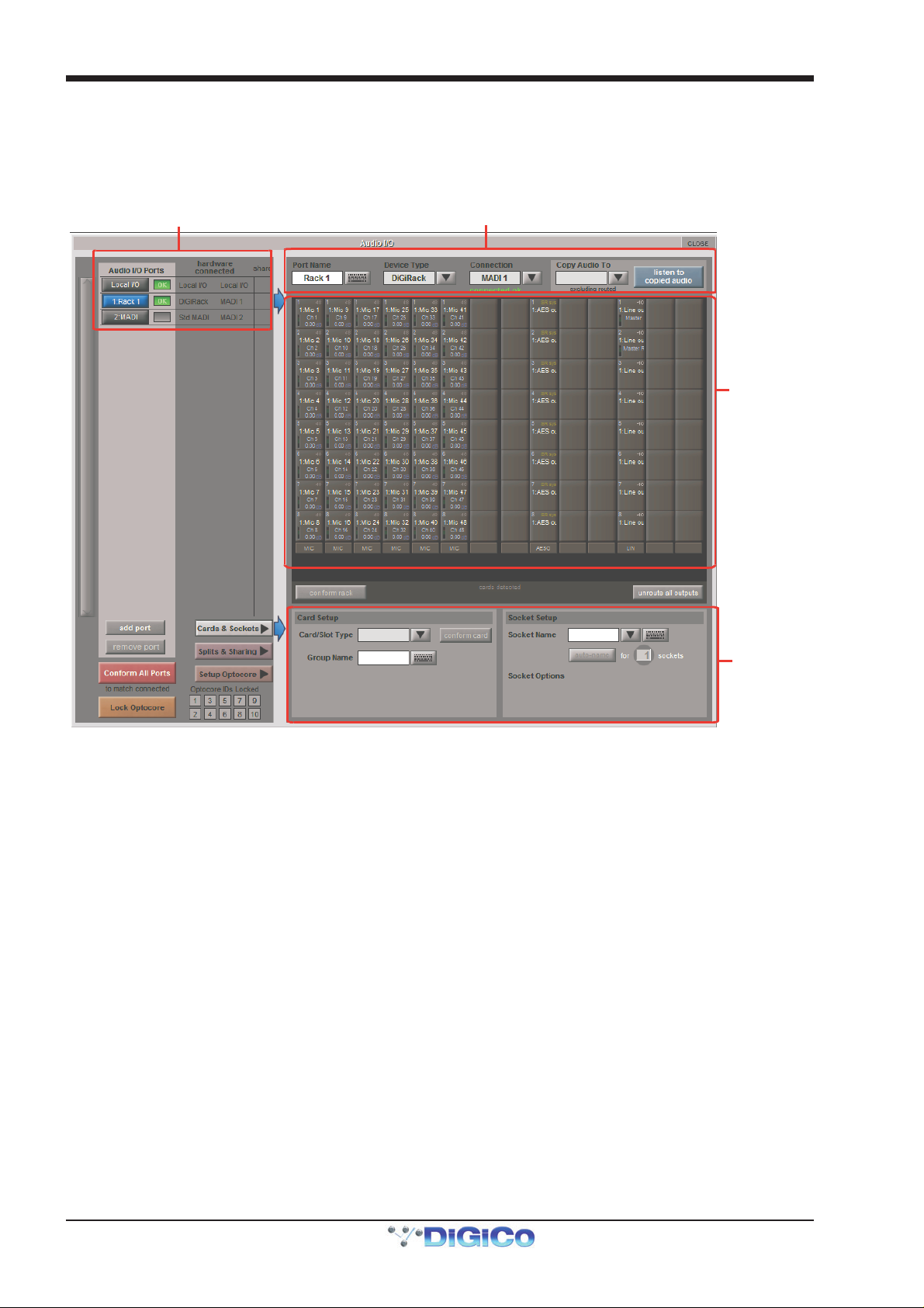
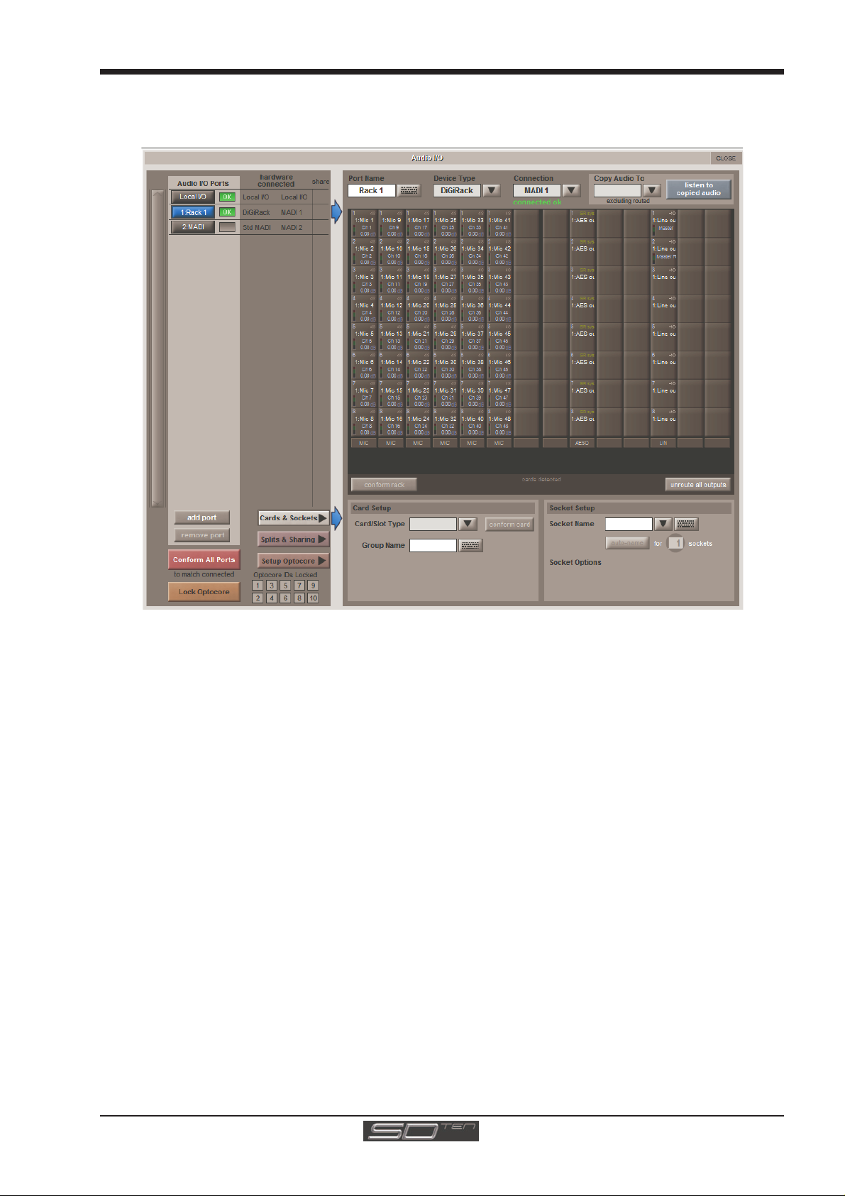
1.4.2 Audio I/O Panel.....................................................................
The Audio I/O window is used to configure the physical I/O connected to the SD10, including configuring and naming the sockets
of the cards installed in racks, and the setting of Pads and phantom power.
Local I/O : The SD10 provides local audio I/O in the rear of the console. These operate independently of connected racks.
To access the SD10 Audio I/O Setup touch Setup>Audio I/O on the Master Screen
The Audio I/O window that opens is divided up into the following sections:
Port selection
Graphic of
connected
rack
Cards & sockets,
Splits & Sharing,
or Optocore setup
The top-left corner of the window shows the ports. Each port relates to an available physical audio connection (Local IO, MADI
Ports or optional Optocore connections).
The top section to the right of this contains the controls relating to the ports. When a port is selected, this section changes to
reflect the status of the selected port, and allows it’s configuration to be changed as required.
Below the port controls is a graphical representation of the rack configuration connected to the selected port. Depending on the
port selected, the graphic will change, showing the available physical I/O. Each small “square” on the image represents a single
physical audio connection or socket, with these arranged in columns or rows, representing I/O cards in racks, or the local I/O on
the back of the console.
The section below the graphical rack picture displays one of three things, as selected by the coloured buttons to its left:
- Select Cards &Sockets to configure the cards or slots and sockets, including
custom naming, phantom power and pad selection.
- Select Splits &Sharing to configure the sharing of card control between consoles
and split outputs on an SD Rack
- Select Setup Optocore to configure optocore connections (See the separate
Optocore v221 manual)
The local I/O configuration is fixed, so no hardware changes are possible. You can, however, change the Port Name, the Group
Names and the Socket Names (the name of each physical connector on a card).
Note that Setup Optocore only applies (and only appears) if the session is setup to use Optocore version 221.
1-10
Page 19
Chapter 1 - Getting Started
Rack Connections
With a Rack selected in the left hand port selection list, the window will change to look something like the image below, depending
on the cards installed in the connected rack. The graphic shows the 14 available cards/slots, 7 input & 7 output.
In order to use the rack, the on-screen contents of the rack must match the cards physically installed in the rack connected. There
are two ways of achieving this :
Manual Conforming of Rack:
Select each card (column) and manually select the appropriate card in the Card/Slot Type drop down menu in the lower section of
the window (displayed when the Cards & Sockets button towards the bottom-left is selected). Once the correct card type is
selected, the Label at the bottom the selected card will turn green, indicating the card type matches the card installed in the rack. If
the Card Type name is Red, then there is a mismatch, and the error should be corrected by selecting the correct card type.
Automatic Conforming:
There are three levels of automatic conforming:
- globally, using the red Conform All Ports button in the bottom left of the window;
- on a rack-by-rack basis, using the conform rack button just below the rack view
section of the window;
- on a card-by-card basis, by selecting a socket from the card in the graphical display
and using the conform card button next to the Card/Slot type button selector in the
lower section of the window. (Note that the Cards & Sockets button towards the
bottom-left should be selected)
Pressing any of these buttons will correctly select the card types for the range in question. Once complete, all of the Card Labels
beneath each slot should turn green.
Copying Audio and Listening to Copied Audio (External Recorder Setup)
Any incoming MADI or Optocore stream can be copied to any MADI Output by selecting the incoming Port in the Ports list (in the top
left of the panel) and selecting the MADI output in its Copy Audio To drop-down menu (in the top right of the panel). The console
will send the 56 channel MADI stream to the selected output.
In addition, by connecting a MADI return from the external device (the playback from a recorder, for example) to its corresponding
MADI input on the console, it can be monitored in the same channels as the original source material: press the Listen to Copied
Audio button. Press the button again to return to normal monitoring.
1-11
Page 20
Chapter 1 - Getting Started
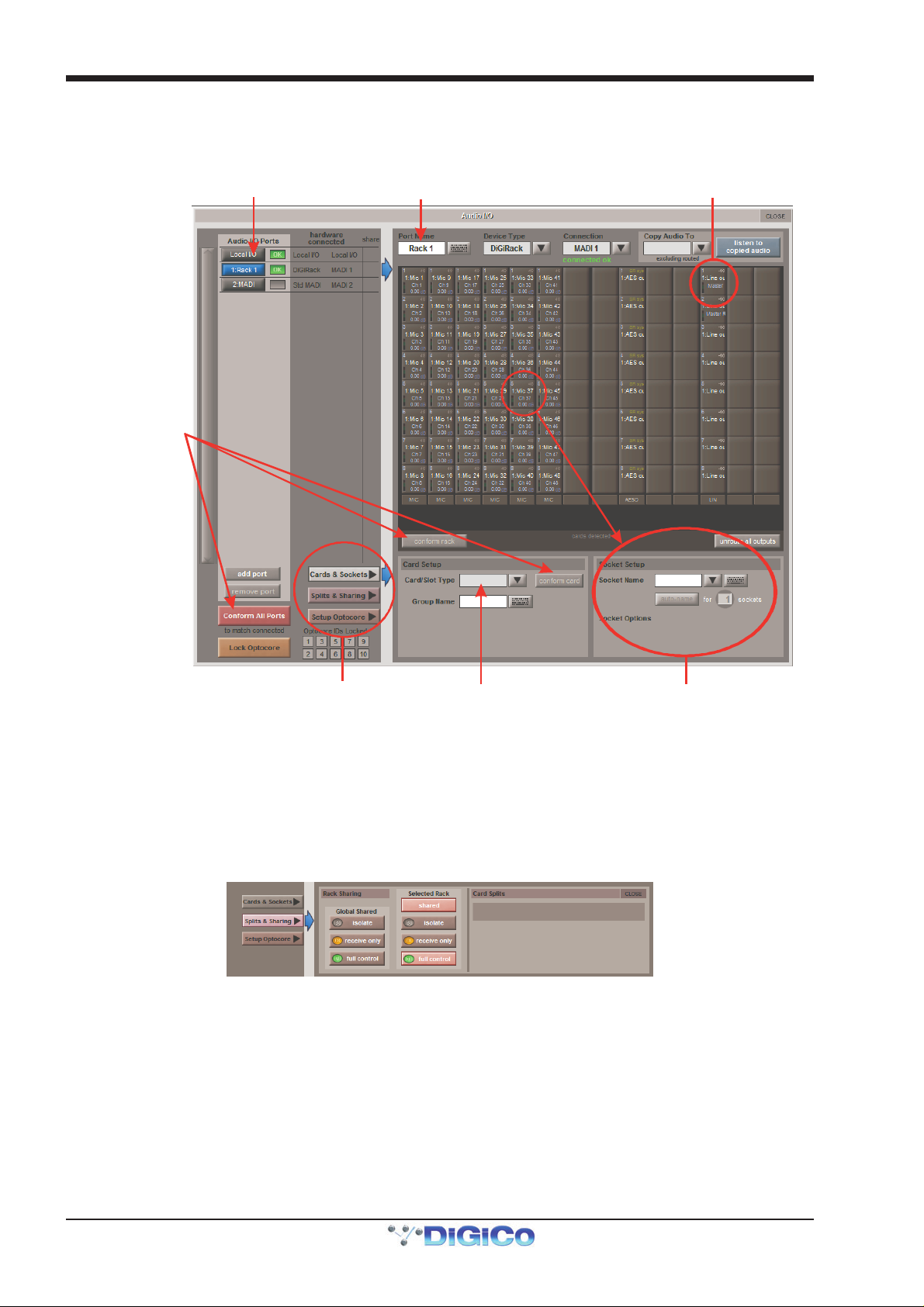
Edit the Port Name here.
Eg. Stage Rack, Local Rack etc...
Analogue Line Out
A
i
o
Select the contents of the bottom-right
Standard MADI Connections
If you have a standard MADI connection (not a DiGiCo Rack) to your SD10, you can set the SD10 to display the MADI with generic
signal names, i.e. MADI 1, MADI 2.. etc. through to MADI 56 instead of the usual rack style names. The naming does not affect the
signal, but makes routing signals easier.
uto Conforming for all ports,
ndividual racks,
r individual car ds
Select the port to be configured
Socket with -10db Pad
corner of the Audio IO window
Select Card Type manually or
using Auto-Conform function,
and edit Group Name
Selected Socket Properties
Edit Name and Socket options.
Console to Console routing
If two DiGiCo consoles are connected together, it is possible to route audio between them.
Splits & Sharing
In a multi-console system where Racks are connected with MADI and shared between two DiGiCo Consoles, only one of the
consoles can take control of the rack, with respect to Gain, Phantom Power and Pads. To overcome this, it is possible to place the
SD10 into one of 3 states of operation; Isolate, Receive Only or Full Control.
Sharing is configured in the bottom right-hand corner of the window when the Splits & Sharing button is selected:
These three states can be set individually in the right column), on a per-rack basis (middle column), or globally for all shared racks
(left column).
Isolate : The SD10 will not communicate with the rack and therefore any adjustment of input gain or +48V switch will have no
effect on the rack settings
Receive Only : The SD10 will receive the rack’s existing settings but will not be able to control the gain etc on the racks.
Full Control : The SD10 will send its settings to the racks and change them accordingly.
1-12
Page 21
Chapter 1 - Getting Started
Total number
Option to Clear
parts of the session
Option to automatically
when using the Clear function
Touch numbers to
S
1.5 Configuring a Session
The SD10 has a default setup which means that the new user need not get involved in configuring the desk at this stage. However, here is a brief overview of how the different displays are used in putting together a session. Each of the master displays
introduced below are described fully within the rest of the manual.
The Setup > Audio IO display is used to configure the physical I/O connected to the SD10, including configuring and naming the
sockets of the option cards installed in racks, and the setting of pads and phantom power. (See previous section)
The File > Session Structure display is used for configuring how the console’s the DSP channels are divided between channel types, and is also where the format of the channels is defined.
The Session Structure display can be used to automatically assign the channels to the worksurface. However, channels can
also be manually added to the worksurface using the Layout > Channel Faders display.
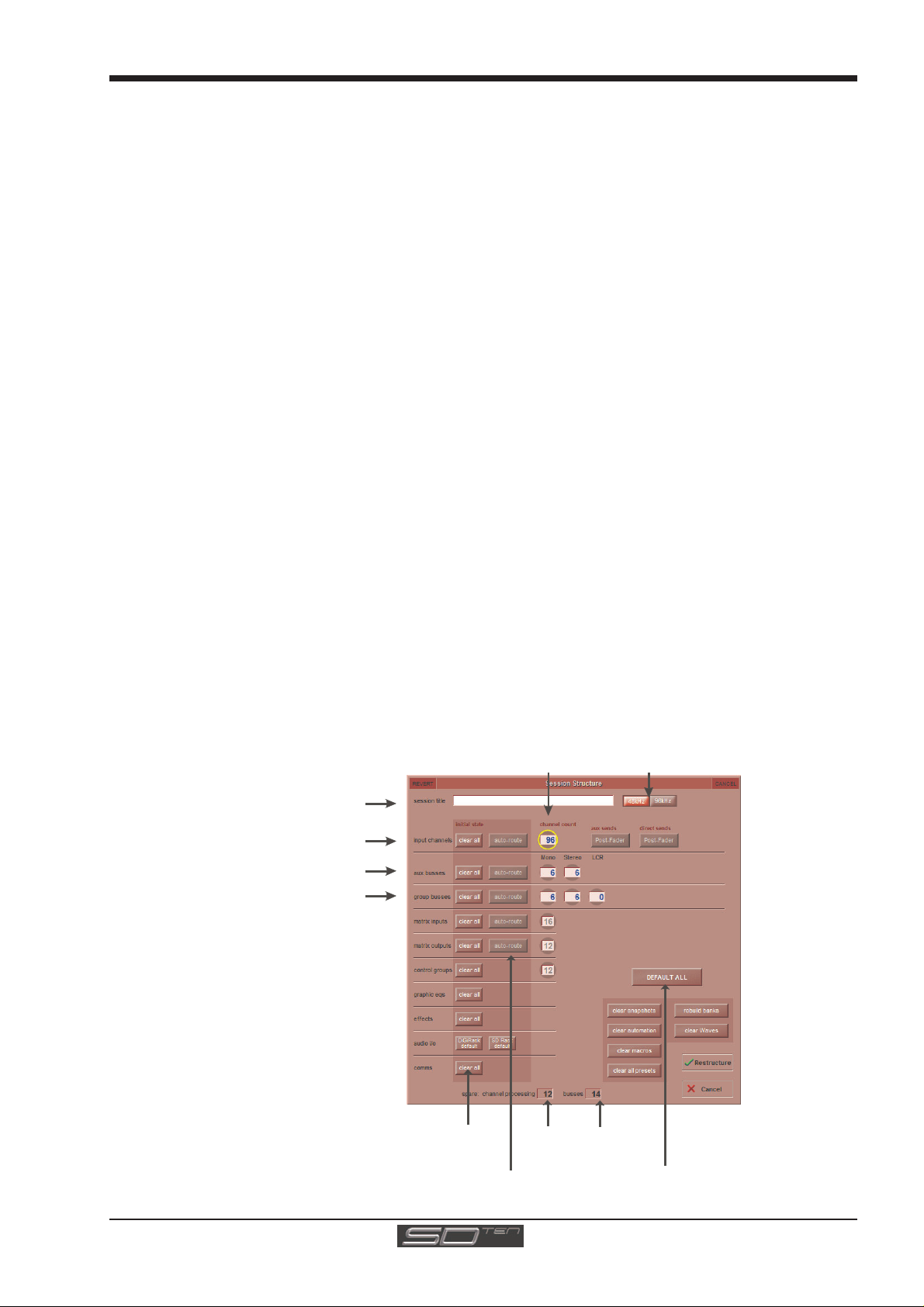
1.5.1 Session Structure..................................................................
When starting a new session, it is important to decide how many of each type of buss is required. While changes to session
structure can be made once a session has been started, it is best to try and set these parameters before configuring the session.
The structure will set the number and type of aux and group channels and allow you to choose which parts of the new session
will be cleared and reset. There is also an option to automatically route the inputs and outputs from channel types that you have
opted to clear.
To adjust any of the channel allocations, touch on the associated channel count box, and either enter a number using the pop-up
number keypad, or adjust using the assigned touchturn controller.
The maximum total amount of Aux and Group channels available is 48. As you increase the number that you require you will see
the resources available decreasing accordingly in the number boxes at the bottom of the panel.
Note - Pressing the Default All button followed by the Restructure button will automatically configure a new
session with the following setup where the first 96 rack inputs are routed to input channels 1-96 and the
Master Buss is routed to Local outputs 1 & 2 and also to rack outputs 1 & 2. All input channels will be routed
to the Master Buss and the console headphones will be fed by the Master Buss when nothing else is soloed.
The default configuration is :
96 Input channels (Adjustable)
6 Mono Aux busses & 6 Stereo Aux busses (Adjustable)
6 Mono Group busses & 6 Stereo Group busses (Adjustable)
16 Matrix Inputs and 12 Matrix Outputs (Fixed)
12 Control Groups (Fixed)
1 Stereo or LCR Master Buss (Fixed)
2 Mono or Stereo Solo Busses (Fixed)
Select session
sample rate
Enter Session title
Set number of input channels
and define sends
Set number and type of Aux
et number and type of Group
edit with pop-up
keypad or touchturn
when restructuring
route inputs/outputs
of unallocated
processing
Total number
of spare
busses
Create a default session
with flat parameters
and basic routing
1-13
Page 22
Chapter 1 - Getting Started
C
Clear All Buttons : When changing routing, you have the option of clearing any non-default routing or processing (EQ, dynamics
etc) from the channels in the session. This is especially useful when restructuring an existing session to make a new session.
The clear snapshots, clear automation and clear macro’s perform similar operations.
Rebuild Banks: When changing the session structure, there are two possible scenarios. If you restructure the session without rebuilding banks, any additional channels you have allocated are not “placed” on the worksurface, and need to be manually assigned to faders. If however, you restructure a session with Rebuild Banks enabled, the worksurface will be built with all channels available on the worksurface.
Aux Sends and Direct Sends: By toggling the state of the Aux Sends and Direct Sends Buttons in the Input Channels section, it
is possible to change the default operation of the Aux Sends and Direct Sends. These functions toggle between “Post Fader”,
“Pre-Fader” and “Pre-Mute”. These buttons can only be used in conjunction with the clear all function.
Auto-Route: The Auto-route functions automatically routes consecutive inputs for input channels, and consecutive outputs for busses. For example, auto-routing 60 inputs will route the first physical input (eg 1:Mic 1) to input channel 1, the second physical input (1:Mic 2) to input channel 2… until you either run out of inputs or channels. Auto-routes are as follows :
Input Channels auto-route with physical inputs
Aux, Group and Matrix Channels auto route to physical outputs
Matrix Inputs auto-route with group outputs
NOTE: Auto-Routing can only be used in conjunction with the “Clear All” button.
Session Sample Rate: The Session Structure window is also used to set the session's sample rate. Use the buttons to the right
of the session title box to switch the sample rate between 48kHz and 96kHz.
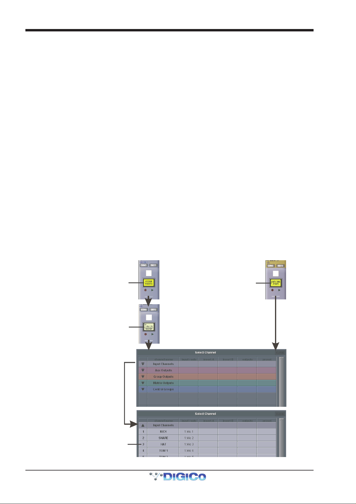
1.5.2 Assigning Faders to the Worksurface .................................
If, after a Session Restructure where the Rebuild Banks button was not pressed, you find that newly created channels do not
appear on the worksurface, open the Layout>Channel List panel on the Master screen and you will see a full list of all input and
output channels that are present in the session.
Channels can be assigned to the worksurface individually (in order to create custom banks of mixed channel formats) or as
complete banks.
First, select a bank and press the LCD Function button.
To create a custom bank, press the Channel Select button below the display labelled Assign Faders followed by the LCD button
on the fader to be assigned (or select multiple faders to assign consecutive channels). To create complete a complete bank, press the Channel Select button labelled Copy Bank From. Having selected the faders or bank, press the first channel that you wish to assign on the Layout/Channel List on the Master
screen.
Consecutive channels will be assigned to the selected worksurface faders.
Now press the LCD Function button again and return to the standard mode by pressing the LCD button labelled Solo
ustom Fader Assignments:
Press LCD Function button
then Assign Faders
Press LCD button(s)
Whole Bank Assignments:
Press LCD Function button
then Copy Bnk From
for Assignment
Open
Layout/Channel List
Click down arrow
to expand list
Touch first channel
to assign
1-14
Page 23
Chapter 1 - Getting Started
Enter a Filename
Enter a Description
I
er
Select a File
File Details
I
d
1.6 Saving and Loading Sessions
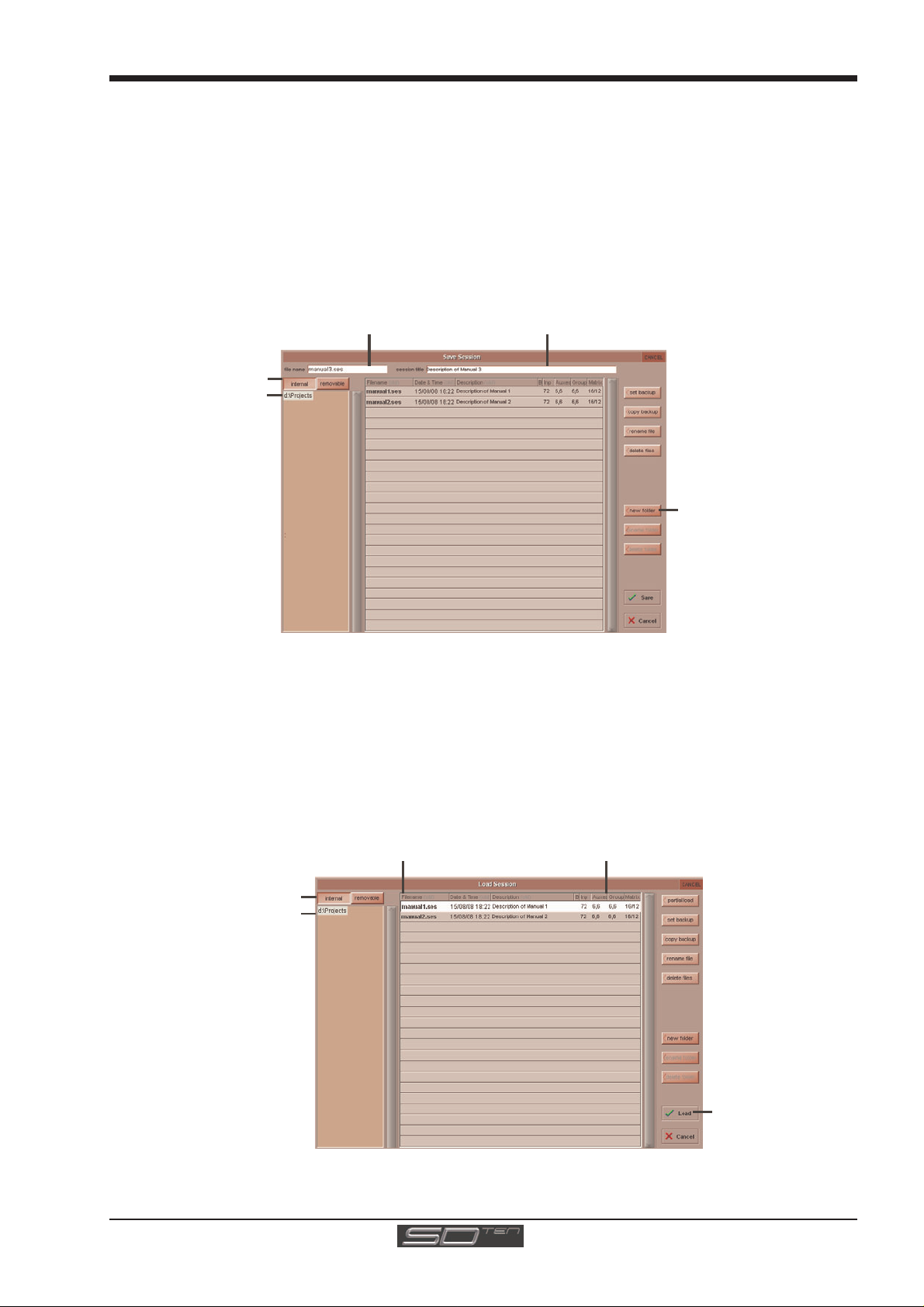
1.6.1 Save As New File .................................................................
When you change the configuration of the a session you should save under a new filename.
If the Save Session panel has not appeared automatically after a session restructure then touch the Files button on the Master
screen and then press Save As New File.
Select the destination drive (Internal or Removable) and file path and then enter a new file name and description for the file - then
press the Save button.
The USB connection for the removable drive is located in the top right hand corner of the centre section.
Note: If you touch a session name on the existing list, this name will automatically be selected as the new file
name and touching Save will overwrite the old file.
Select Inte rnal or
Removable USB
nternal files saved
in D:\Projects
To create a new fold
in D:\P rojects
1.6.2 Save Session ........................................................................
This button which is found above the Save As New File button will save the existing session in the same location and under the
same file name as it was previously saved or loaded from. It therefore serves as a "Quick Save" option to update an existing
session.
Remember that this function will overwrite your last saved version. If you wish to save the session under a new name use the Files menu button and select Save As New File (See above).
Load Session
To load a previously saved session:
Touch the Files button on the Master screen and then press Load Session.
Select the source drive (Internal or Removable) and the required file from the list - then press the Load button.
Select Inte rnal or
Removable USB
nternal files saved
in D:\Projects
Press Loa
1-15
Page 24
Chapter 1 - Getting Started
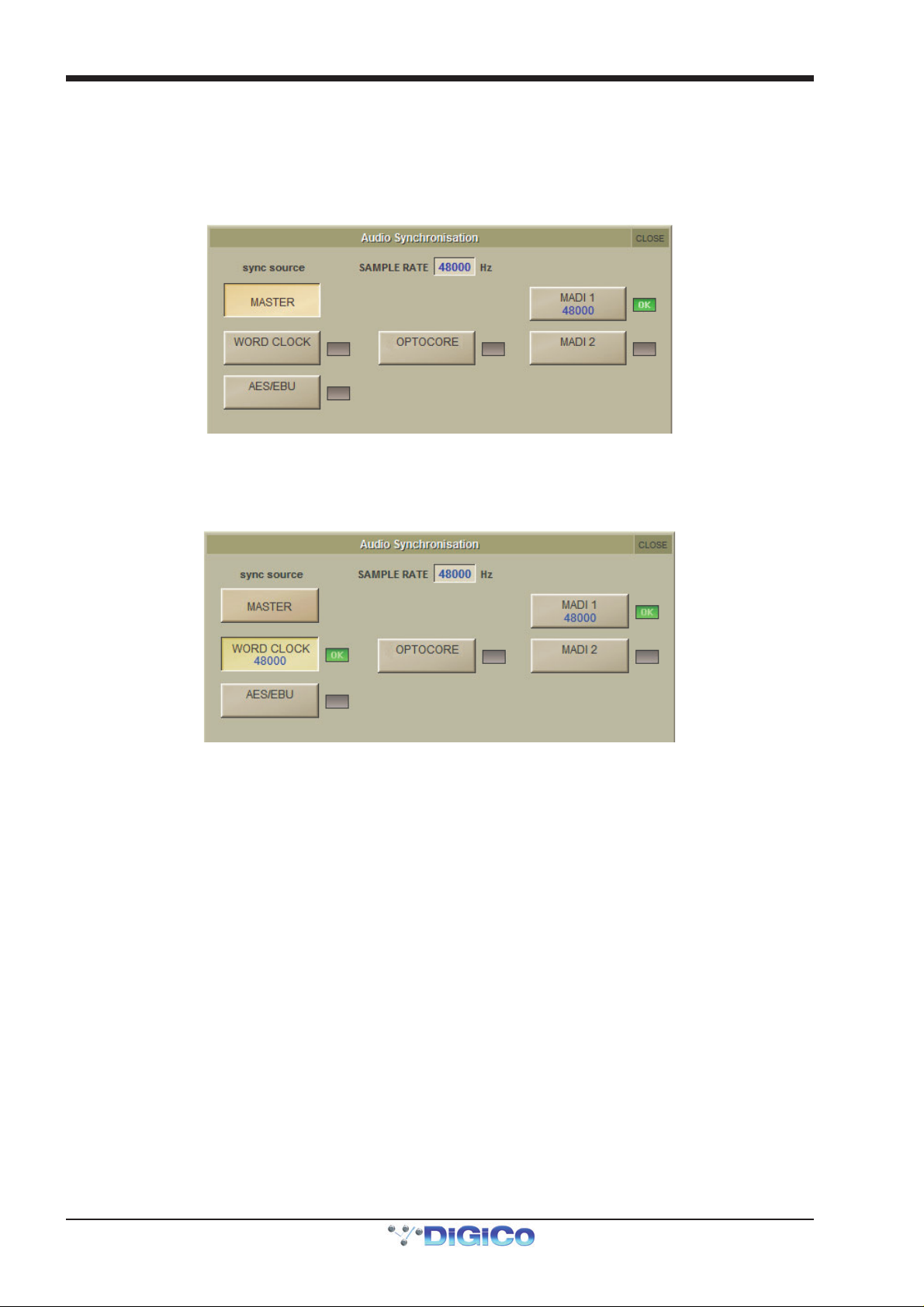
1.7 Audio Sync
The SD10 will operate at Sample Rates of either 48000Hz (48kHz) or 96000Hz (96kHz). By default, it is set to clock internally (as a
Master) at 48kHz. To switch the clock to 96kHz, open the Session Structure dialogue in the File menu and click on the appropriate sample rate button at the top of the window.
Within a normal setup, the SD10 will usually remain as clock master. However, there are times when the SD10 needs to be
clocked externally. The Audio Sync panel allows you to control external synchronisation.
To access the Audio Sync Panel, touch the Setup Menu button, followed by Audio Sync. A panel similar to the below will open.
The SD10 will clock from the following sources : Word Clock, AES/EBU, MADI & Optocore (if fitted)
Note : When a valid clock is detected on an external sync input, the corresponding Green OK box will light, even if that input is not
selected as the clock source for the SD10.
Example External Clocking : Word Clock @ 48kHz
1-16
Page 25
Chapter 1 - Getting Started
Touch top of
Select or type
S
S
1.8 Routing Basics
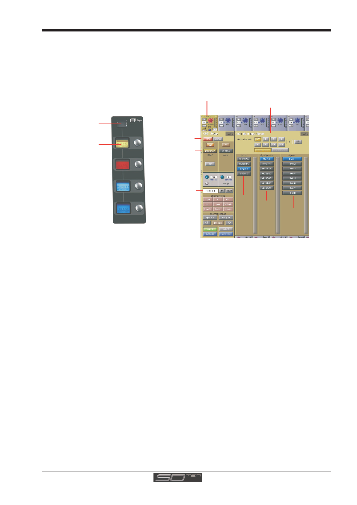
1.8.1 Selecting Inputs & Outputs...................................................
All channel input, output, insert send and insert return routing is done via routing displays, accessed via the dark grey routing
buttons in the channel Setup and Output displays (shown below for an Input channel’s input).
To access Channel Input Setup, touch the top of an input channel display on the touchscreen.
To access Channel Output Setup, touch the bottom of any channel type's display on the touchscreen.
Input Channel
elect a Layer
Mono/Stereo
elect a Bank
Press Main Input
Label Channel
Within each display, there are three columns containing three levels of routing selection:
- The left-hand column contains the available ports within which the desired input or output might be located;
- The middle column, signal groups, then shows the available groups of inputs or outputs within that port;
- The right-hand column, signals, then displays the individual inputs or outputs available within that signal group.
Number of Inputs
to Ripple Route
Select
Rack
Select
Card
Select
Socket
The boxes in each column are lit blue to indicate that they are currently selected. If there is already a routing assigned within the
display, the port and signal group columns containing the current assignment will be half-lit.
Each output can only have one channel routed to it. The outputs that are currently in use by another channel display in blue text. If
you attempt to route a different channel to an output which is already in use, a confirmation box appears, indicating which channel
is already using it, and warning that continuing with the action will cause the old channel to be derouted from this output. Press
Yes to proceed, No to cancel.
Note that when routing direct outs from Input channels or outputs from output channels, any number of
available signals can be selected. A new route selection will therefore be added to previous selections in
these cases. However, inputs, insert sends and insert returns can only route to/from one signal (in the case of
mono channels) or two signals (in the case of stereo channels). A new route selection will therefore result in
the previous selection being lost for inputs and insert sends and returns.
For stereo channels, left and right routes are presumed to be consecutive: When routing stereo signals, select the left route, and
the next signal in the list will be automatically selected as the right route. If the last signal in a signal group or port is selected as
the left route, the first signal in the following signal group or port will selected as the right route.
Note: If Waves is enabled, a Waves port will be displayed. See the relevant appendix for more details.
For input and insert return routing, the INTERNAL port provides the following signal groups:
Misc: The oscillator, white and pink noise generators.
Graphic EQs: The outputs of the SD10’s internal graphic EQ’s.
Effects: The outputs of any effects sends that have been created
Channels: The direct outputs from the other input channels
Groups: The outputs of the group busses
Auxes: The outputs of the auxiliary busses.
1-17
Page 26

Chapter 1 - Getting Started
Note: The outputs for the channel being routed are locked out of the signal list.
Note also that the console views all routes as a single list. Therefore, if the left signal is connected to the last
signal in a port, the right signal, will be automatically connected to the first signal of the next port, regardless of port type.
For output and insert send routing, the INTERNAL port provides access to the inputs of the SD10’s Graphic EQ’s, and the inputs to
any effects that have been created.
The 0:Local I/O port contains a list of the inputs or outputs found directly on the SD10’s back panel. The Rack ports contain all of the inputs or outputs available within the remote I/O racks, as defined in the Audio I/O display. The mono > mono and mono > stereo buttons define whether sends from mono channels to the console's Internal effects and
Waves effects (see the relevant appendix) are mono or stereo.
Once a route has been selected, its name will appear below the routing button in the Setup or Outputs display.
Whenever a route is created, metering and additional controls are made available below the routing button. These controls are
dependent on the type of route created, and are described in detail within Chapter 2 where necessary:
Local input routed to an input or insert return: a Line or Mic selector.
Line input routed to an input or insert return: no additional control.
Mic pre-amp routed to a mono input: a 48V button for remote control of phantom power, and delay controls.
Mic pre-amp routed to a stereo input: a 48V button, delay controls and pan controls.
Mic pre-amp routed to an insert return: a 48V button, phase reverse (Æ) button and gain trim.
Output routed to a console output: a -10db pad (rack out only), on button for switching the send on and off, gain trim
Insert send routed to a console output: a -10db pad (rack out only), on button for switching the send on and off, and gain
Insert send routed to a graphic EQ: an on button for switching the send on and off
Output routed to a graphic EQ: no additional control.
and send point selector which toggles the place within the channel from which the
direct output is fed:
pre-F Pre-fader,
post Post-fader
pre-M Pre-mute (and pre-fader)
trim.
Buttons become ringed in either red or green to indicate that they are on.
1.8.2 Ripple Channels ...................................................................
The ripple channels function, located at the top of the route display, allows consecutive channel routes to follow the routing of the current display incrementally. For example, Channels 1 to 8 direct outputs can be routed to Rack 1 > Line outs 1 to 8 respectively by routing Channel 1’s direct out to Rack 1 > Line out 1 and allowing the ripple channels function to route Channels 2-8 automatically.
The number of channels to be rippled is defined either by selecting the appropriate grey numbered button, or by selecting the
keyboard button to the right of the numbered buttons, typing the required number of channels (8 in the example above) into the
numeric keypad which appears, and pressing OK. Once you have configured the ripple channels function, any routing action
will also effect the appropriate number of channels above the channel being routed.
The ripple channels function treats stereo channels as two channels. In other words, if Channel 2 in the above example is
stereo, the ripple channels function will route Channel 1 to Line out 1, Channel 2 Left and Right to Line outs 2 and 3, Channel 3
to Line out 4 etc.
1-18
Page 27
Chapter 1 - Getting Started
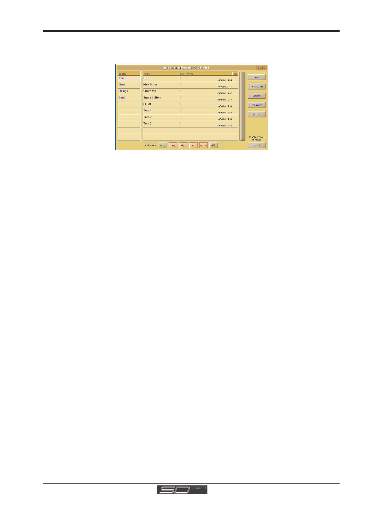
1.9 Presets
Presets are used for storing and recalling settings for channels, fx units, graphic EQs and the matrix. While each preset functions
slightly differently, this section provides a basic understanding of how to use the various preset displays:
The left-hand column of a preset display contains the available groups of presets, and touching one of these groups brings up
the list of presets within that group in the column to its right (name). The columns to the right of the preset name displays the
number of channels whose settings are included in the preset (chs) (Channel and Matrix presets only), the date and time it was
created or updated (notes), and whether or not it is locked (lock).
Note that a presets display will only list presets of the relevant type.
To recall a preset, touch the name of the group containing the preset you wish to recall, and then touch the preset’s name. The
recall scope buttons at the bottom of the some preset displays allow you to select which elements are recalled and which
elements remain unchanged. The buttons are included in the recall when they are lit.
To save the current settings as a new preset, touch the group in which you want the preset to be stored and press the new
button. The new preset is automatically named according to the preset type. To alter the preset’s name, type the new name using
the keyboard display that appears (or the external keyboard) then, if relevant, touch and edit the number of channels’ settings that
you want to store in the preset (the default is one channel). Now touch OK.
Note that pressing CAN in the keyboard display will cancel the display but create the new preset with its
default name.
To save the settings as an update of a previous preset, press update, touch the preset you wish to overwrite, and press Yes in
the confirmation display which appears.
Note that when updating a previous preset, failing to press update will result in the preset you wish to overwrite being recalled, and the settings to be saved being lost.
To create a new group of presets, press new group. A new group will be created, called group n, where n is the next available preset group number. To alter the group’s name, type the new name using the keyboard display that appears (or the external keyboard) and touch OK.
Note that pressing CAN in the keyboard display will cancel the display but create the new group with its
default name.
The edit name button allows preset names and group names to be edited, and the preset to be locked, preventing them from
being edited, overwritten, or deleted. The button lightens to indicate that it is active. To edit a preset’s name, make sure the preset
is unlocked (see below), activate the edit name button and touch the preset’s name. Type the new name in the keyboard display
and press OK. To edit a preset group name, activate the edit name button and touch the group name. Type the new name in the
keyboard display and press OK.
To lock the preset, activate the edit name button and touch the preset’s lock column. A grey padlock appears, indicating that the preset is now locked. Touching the lock again with edit name active unlocks the preset.
To delete a preset, press delete, touch the preset to be deleted, and press confirm. To delete a consecutive range of presets,
press delete followed by select range, touch the first and last preset to be deleted and press confirm. To delete one preset,
or a nonconsecutive range, touch each preset to be deleted and press confirm. To delete an entire group of presets, press
delete followed by select all, then press confirm.
1-19
Page 28
Chapter 1 - Getting Started
1.10 Naming Channels and Busses
A large number of elements within the SD10 can be custom named. Access to the naming facility is via black and white text boxes
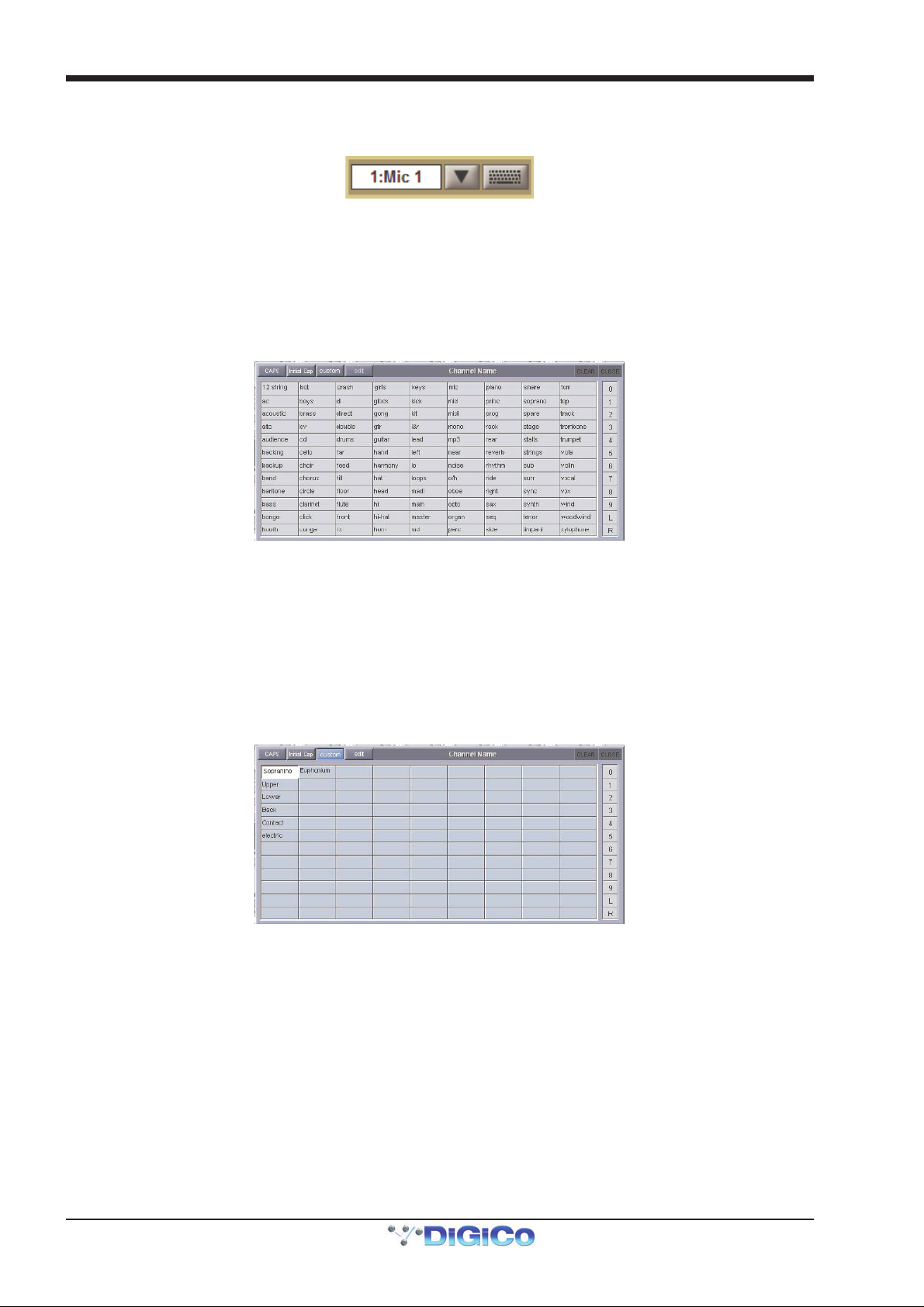
with down arrow and keyboard buttons to their right, such as shown here:
To create a name manually, touch the text box or the keyboard symbol to its right to bring up a QWERTY keyboard display. This keyboard includes standard Caps, Shift and Delete functions, as well as Cut , Copy and Paste functions which can be used to move name text between channels. The arrow buttons in the bottom left-hand corner of the keyboard display move the cursor within the text box. Create the new name, either using the on-screen keyboard display or the external keyboard, and press OK. To close the keyboard display without changing the name, press CAN. To move the keyboard display to the following channel, press Next (or TAB on the external keyboard).
The Channel Name display enables commonly used words to be inserted quickly without the use of the keyboard. This facility is available not only when naming channels but also when naming other elements. To open the Channel Name display, touch the down arrow immediately to the right of the Setup display’s channel name text box.
Touching any word from the display inserts that word into the channel name text box. Further words can then be added to the
channel name in the same way, divided by a single space. Numeric and L/R identifiers can be added from the column down the
right-hand edge of the display. Text can be entered in CAPS or Initial Caps by pressing the CAPS and Initial Cap buttons in the
top of the display. If neither of these are selected, all text is inserted in lower case.
Note that the first text to be inserted from the Channel Name display when it is opened overwrites all previous text.
Note also that text that extends beyond the end of the text box will not be visible!
In addition to the standard word set, a list of user-defined words can be created and inserted by pressing the custom button,
located next to the Initial Cap button. The button lightens to indicate that the custom set is displayed.
To add a new word to the custom set, touch the box which you want to use and press edit, located next to the custom button, to bring up a QWERTY keyboard display. Type the required word and press OK. In this keyboard display, the Next button saves any text inserted in the current box and moves the keyboard to the next box in the custom list. To cancel the keyboard display, press CAN within the display, or press edit again. The words in the custom list are inserted into the channel name text box in exactly the same way as words in the standard list. Pressing custom again returns the display to the standard word set.
Tip: As custom names appear in the box in which they are typed, they are not automatically alphabetised.
The user may find it helpful to define a system for ordering the custom page.
Note also that the standard word set cannot be edited.
The current name can be cleared by touching the CLEAR button towards the top right-hand corner of the Channel Name display. The Channel Name display can be closed by touching the CLOSE box, in the top right-hand corner.
1-20
Page 29
Chapter 1 - Getting Started
EQ
Presets
HPF/LPF
4 Bands
Processing Order
1.11 Channel Processing
1.11.1 EQ.........................................................................................
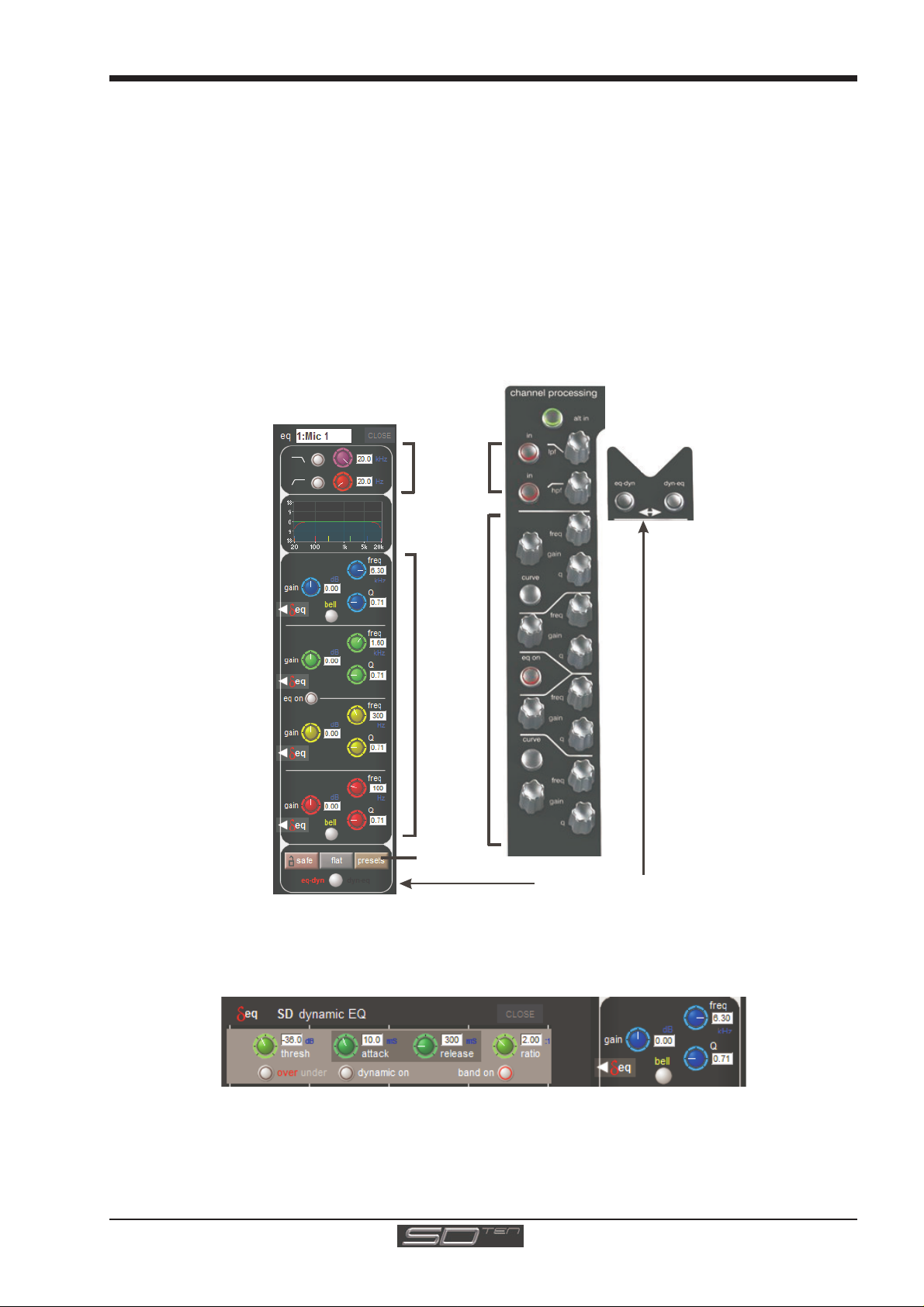
On input channels, the EQ section comprises four user-configurable parametric filters and a pair of swept High-pass and Lowpass filters. On output channels, there are eight bands of EQ and no filters.
The EQ is accessed by touching the on screen display to Assign the channel (the colour changes to yellow) and then using
the controls on the right hand side of the screen.
When a control is adjusted the expanded view seen below appears in the input screen but this view can be seen at any time by
touching the EQ response graph on the screen.
Note - If the expanded view does not appear when a control is adjusted open the Options panel and set the
Auto Expand EQ option to Yes
Touching the normal EQ response graph will show an expanded view in a separate panel.
The order of EQ and Dynamics in the channel signal path can be changed using the worksurface button to the right of the
worksurface HPF and LPF controls.
The type of filter used by the top and bottom bands can be changed by successive presses of the Curve button for that band.
Dynamics are available to each EQ band – dynamic EQ modules can be assigned to a maximum of 10 channels. Clicking on the
'delta' EQ button below the band's gain control will open up its Dynamic EQ display:
1-21
Page 30
Chapter 1 - Getting Started
A
C
t
n
A
1.11.2 Dynamics .............................................................................
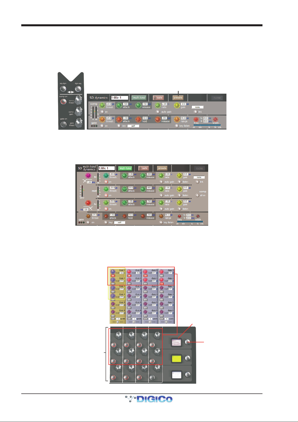
The dynamics are accessed by touching the words Comp or Gate just below the EQ graph on screen to open the dynamics panel.
The worksurface controls beneath the screen control the various parameters. Touching the Close button in the top right corner
of the panel will close it.
Dedicated Threshold, Gain controls and In/Out switches can be found on the right hand side of the centre section's
worksurface. These can control the Assigned channel's dynamics whether the on screen dynamics panel is open or not.
Dynamics Presets
The Assignable encoders and switches beneath the screen can be assigned to any of the main dynamics controls. Hold the Assign Switch button on the left of the input section and touch the dynamics control required on the screen. The selected control is shown by the Status Display.
Multiband Compression is available for up to 10 channel dynamics modules. Click on the multi-band button at the top of the
display to access the 3 dymanics bands:
1.11.3 Auxiliaries ...........................................................................
The auxiliaries can be accessed by touching the auxiliary row on screen or using the Screen Scroll buttons on the left of the worksurface
Using either of these methods, the highlighted auxiliaries on the input screen will change. The 3 rows of rotary controls and
switches in each worksurface section are used as auxiliary sends, pans (with 2nd Function ON), On/Off and pre/post switches
(with 2nd Function ON).
ssigned
ontrol LCD
Hold then
ouch scree
ssignable Aux Send Controls
Touch screen to select
to Assign
1-22
Page 31

Chapter 1 - Getting Started
1.12 The Matrix
To open the Matrix Inputs panel, touch the Matrix button on the Master Screen Menu. The window that opens allows you to route
inputs to the Matrix Output Channels, and set the Matrix crosspoint levels.
To route an input, touch the top of the appropriate Matrix column. This opens a standard SD10 input routing page.
Matrix Input Routing
Matrix Crosspoint
Level Control
Matrix Snapshot
Safe control
Matrix Preset Control Touch-turn assignments
The example above has the Master Stereo Buss routed to the inputs of Matrix 1 and Matrix 2 (Labelled as PA LEFT & PA RIGHT).
By adjusting the crosspoint levels, you can change how much of each side of the Master buss is fed to these Matrix Channels.
There are three modes of level adjustment : multi, single & all.
Multi : Touch one or more level “knob” on screen, then adjust using the Touchturn control. Single : Touch any level “knob” and adjust. Touching another “knob” will deselect the first. All : All “knobs” are adjusted at the same time.
When adjusting more than one crosspoint, their relative levels are maintained.
Note that Matrix outputs are named in the Matrix Channel displays.
1-23
Page 32

Chapter 1 - Getting Started
1.13 Control Groups
Any number of input channels and output channels can be connected to one or more of the 12 Control Groups. They can then all
be operated from a single worksurface channel. Changes to the Control Group fader, mute or solo or controls will affect all
channels connected to the group.
There are 2 methods to set up Control Groups:
1) Press the LCD Function button on a CG fader bank (normally found in the centre section)
Press the JOIN CG button Press the channel select button for the CG that you want to use Press the channel select buttons for each of the channels that you want to make members of the CG Release the JOIN CG button and return to standard Solo mode by pressing the channel select button beneath the LCD display
labelled SOLO
Press LCD
Function Button
then JOIN CG
2) Press the on screen JOIN/LEAVE button for the required CG channel
Press the channel select buttons for each of the channels that you want to make members of the CG
Release the JOIN/LEAVE button
Press Join/Leave button on required CG channel Press Ch annel LCD buttons to assign members
A list of all the connected channels and their names is displayed above each Control Group display.
You can also clear all the channels from a Control Group by pressing Clear.
When a channel is a member of a Control Group, its own controls can still be adjusted independently of the other Group members.
Adjustments to fader levels are transmitted to the Group members as dB changes, so that a level increase of 2dB on the Control
Group fader will increase all the member levels by 2dB, irrespective of the relative levels of the individual channel faders.
Select Control
Group to join
Press Channel LCD Buttons to assign members
List of members
Control Group Mutes are treated as “in series” where a channel is a member of more than one group – all CG mutes must be off
for channel to be unmuted and muting any CG always mutes all of its members. If a channel is CG muted by single or multiple CGs,
the worksurface channel mute button will override all CG mutes for that channel. The channel will not however be removed from
CG membership, so if the relevant CG is muted again, the channel will also be muted.
1-24
Page 33

Chapter 1 - Getting Started
Solo Trim
Solo Delay
Direct Out Level - Fader Assignment
Direct Out Level
S
w
1.14 Solo Setup
The SD10 Solo panel is accessed from a button at the top of the Master Screen. Some of the controls on this panel are duplicated
on the right worksurface section.
There are two solo busses and each channel on the console can be independently assigned to use Solo1, Solo2 or Solo 1+2.
Therefore, if the console was being used for Stage monitors, the first solo buss could feed “In-Ear” monitors, and the second solo
buss could feed a wedge.
pfl / afl solo mode
multi / sin gle s o lo mode
Clear
Solo level meter
Switch buss between
Mono / Stereo / LCR
elect signal heard
hen no solo is active
Insert routing
Direct Out routing
Headphones On / Off
The following functions are available independently for each solo buss :
- Mono / Stereo Switch
- No Solo source routing
- Insert Point with both internal and external routing capability
- Direct Out routing (eg. for feeding a wedge)
- Assignment of Direct Out level control to master fader or speaker volume pot
- afl or pfl mode
- single or multi solo mode
- Delay
- Level Trim
- Auto solo mode
No Solo : Source for solo buss when no channel is in solo mode. No Solo source does not show on Solo meters.
Auto Solo : If a channel is set to Auto Solo, it will automatically solo when another channel is soloed. The Auto Solo function of
each solo buss can be enabled and disabled as required. The solo buss must be in multi mode for the auto solo function to
operate.
1-25
Page 34

Chapter 1 - Getting Started
1-26
Page 35

Chapter 2 - Channel Types
SD10 Operation Manual
Chapter 2:
Channel Types and Functions
2-1
Page 36

Chapter 2 - Channel Types
2.1 Introduction to Channel Types
This chapter describes all of the functions available within the SD10’s channel strips. The first two parts of the chapter will
examine the Input/Setup and Output sections of each of the types of channel strip, and the third part will cover the in-channel
signal processing, which functions in precisely the same way on each channel type. Those elements which are common to each
channel type are dealt with first, and then those elements which are specific to a channel type are dealt with separately.
In order to understand this chapter, you will find it helpful to have read Chapter 1 (Getting Started).
2.2 Channel Input Setup - Common Elements
2.2.1 Channel Strip Input Area .....................................................
The channel strip input section is located at the top of the channel strip in the Channel Strip panel (shown below for an Input
channel). This is where the channel inputs, snapshot safes, and solo bus feeds are configured. Some basic controls are displayed in the channel strip. However, most of the input parameters are contained in the channel Setup display, accessed by
touching the channel’s input or filters areas at the top of the screen. The Setup display also contains a number of channel
configuration elements.
Note that channels without an external input selected display a simpler input section than that shown here.
The large pot at the top of the input area of the main channel strip controls the input level, and can be accessed using the encoder
immediately above the channel strip. For Input channels which have ADC’s assigned to their inputs, this remotely controls the
analogue gain of the mic pre-amp in the I/O rack. For all other input types, this is a digital level trim. The gain value is displayed to
the right of the level pot.
To the left of the pot there is a phase reverse button which is grey when inactive and red when switched in.
In output channels, the lower half of the channel strip input area contains the input delay controls: The delay is switched on using
the on/off button on below the on screen total delay readout. The button turns red to indicate that the delay is active. The small pot
to its right determines the course delay amount, and the current course delay value is displayed above the on/off switch. The
channel's topmost encoder can be assigned to the delay pot using the rotary assign scrollers to the left of the encoders. On
Output channels, the delay can then be adjusted more finely by pressing the 2nd function button and turning the gain encoder.
This value is displayed in microseconds or milliseconds to the right of the delay pot.
Note that, in Input channels, the lower half of the channel strip input area is used for trim and track controls. The delay function is
found within the Setup display, not in the channel strip.
2.2.2 Channel Names.....................................................................
The black and white text box in the Setup display is used for naming the channel. Channel names are displayed in the scribble
strip at the bottom of the screen. By default, the channel is given the same name as the selected input signal.
Note that if no input signal is selected, the scribble strip simply displays the channel number, prefixed by ch for Input channels,
and prefixed by Aux, Grp or Matrix in the case of output channels.
The following notes are specific to naming channels:
The Next button moves the entire Setup display to the new channel.
At the very top of the channel, the channel number and input signal name are displayed for Input channels, and the channel type
and number are displayed for output channels. These labels remain unchanged, regardless of any channel naming.
For Input channels, note that if the channel input signal is changed once a channel has been manually named, the channel name
will no longer follow the input signal name. To reactivate the automatic channel naming function, clear the name and re-select the
channel input.
Note also that the channel Output display also provides access to this channel naming facility.
2-2
Page 37

Chapter 2 - Channel Types
2.2.3 Channel Safes.......................................................................
The Channel Safes area of the Setup display defines which parts of the channel will be not be affected when snapshots are recalled to this channel.
Note that the above diagram displays the Input channel safes. Output channels display a smaller list of
available channel safes.
Select whichever parts of the channel you want to protect in this way by touching the appropriate button. To cancel a safe, press
the relevant button again. The buttons turn red to indicate that they are safed. The presence of safes within the channel is also
indicated by the label of the appropriate channel part turning red and the background colour of that channel’s name also turning
red.
The EQ and dynamics settings can also be safed and unsafed from within the eq and dynamics displays. The whole channel can also be safed and unsafed by pressing the SAFE button at the bottom of on-screen channel (Offline software). It is grey to indicate that some elements of the channel are not safed, and red to indicate that the entire channel is safed.
Tip: When some elements of the channel are safed, a double-press on the SAFE button can be used to quickly
clear all channel safes.
Note: Channel safes refer specifically to snapshot recalls and do not protect channel settings when using the
copy from, copy to and presets functions described below.
2.2.4 Channel Settings ..................................................................
The Channel Settings area of the Setup display allow channel settings to be copied between channels. The left and right arrow
buttons are used to move the Setup display to adjacent channels.
The copy from button allows settings to be copied from other channels to this channel and those to its right: Pressing copy from opens up a Copy Channels display:
The extent of the channel settings to be copied is selected using the scope buttons towards the bottom of the display. Each button lightens to indicate that it is included in the copy function. The number of source channels to be copied is defined either by selecting the appropriate grey numbered button, or by selecting the keypad button to the right of the numbered buttons, typing the required number of source channels into the numeric keypad which appears, and pressing OK. Press the Channel Select button (shown below) on the left-most source channel in order to action the channel copy. If more than one source channel has been selected, the settings of appropriate number of channels to the right of the source channel will copy to the channels to the right of the destination channel (The current Assigned channel).
2-3
Page 38

Chapter 2 - Channel Types
C
For example, to copy the EQ settings on channels 1-8 to channels 9-16 respectively:
- Make channel 9 the Assigned channel and touch copy from
- In the scope area of the Copy Channels display, select only the eq button
- Set the number of channels to be 8.
- Press the Channel Select button on channel 1.
hannel Select Button
The copy to button allows settings to be copied from this channel to other channels: Pressing copy to opens up a Copy Chan-
nels display:
Note that this is a different Copy Channels display from that opened by the copy from button.
The extent of the channel settings to be copied is selected using the scope buttons towards the bottom of the display. Each
button lightens to indicate that it is included in the copy function. The number of destination channels to which this channel’s
settings will be copied is defined either by selecting the appropriate grey numbered button, or by selecting the button to the right
of the numbered buttons, typing the required number of source channels into the numeric keypad which appears, and pressing
OK. Press the Channel Select button (shown above) on the left-most destination channel in order to action the channel copy. If
more than one destination channel has been selected, the settings of the source channel will copy to the appropriate number of
channels to the right of the selected destination channel.
For example, to copy the EQ settings on channel 1 to channels 9-16:
- Make channel 1 the Assigned channel and touch copy to
- In the scope area of the Copy Channels display, select only the eq button
- Set the number of channels to be 8.
- Press the Channel Select button on channel 9.
If a copy from or copy to function is actioned by mistake, it can be undone by pressing the undo previous copy button in the
current Copy Channels display.
Tip: Use copy to for copying one channel’s settings to a number of other channels; Use copy from to copy the
settings of a group of channels to another group of channels.
Tip: If you wish to make several different copies press the STAY OPEN button on the Copy To panel and it
will remain open until it is manually closed with the CLOSE button
2-4
Page 39

Chapter 2 - Channel Types
Pressing the presets button opens the Presets display. The basic functions of a Preset display are described in the Getting
Started section. Functions specific to Channel presets are described below.
Note that presets are specific to a channel type: The Presets display will only list those presets which apply to
the current channel type.
To reset the channel to the default settings, press default.
2.2.5 Channel Solos.......................................................................
The SD10 has two solo busses, and each channel can be assigned to solo 1, solo 2 or both solo 1 and 2. If the console was
being used for Stage monitors, this would allow, for example, the first solo buss to feed In-Ear monitors and the second solo buss
to feed a wedge.
Note: The solo busses are configured in the master solo displays, accessed by pressing the Solos button at the
top of the Master Screen.
The channel’s solo routing is assigned in the section at the bottom section of the channel Setup display. Pressing the green solo 1 and solo 2 buttons enables the channel to be routed to solo busses 1 and 2 respectively. The buttons are green to indicate that the solo bus is available, and grey to indicate that it isn’t.
Solo buss assignments can also be configured by pressing an lcd function button, followed by the SOLO CHOICE function button which appears. Pressing a channel's LCD button will then cycle the channel's solo buss routing between SOLO 1, SOLO 2 and SOLO 1+2.
Note that each channel must be enabled for at least one solo buss.
When the blue auto solo buttons are active (indicated by white, rather than grey, text), that channel is automatically routed to that solo bus whenever another channel is soloed to that buss.
Note that a list of channels with auto solo enabled is displayed in the auto solo section of the master solo
display. The auto solo function has to be activated by pressing the blue enabled button below the auto solo
list in the master solo display.
2-5
Page 40

Chapter 2 - Channel Types
Tip: If you are using effects returns, selecting auto solo can allow soloed tracks to be auditioned with their
effects returns.
2.3 Channel Output and Inserts - Common Elements
2.3.1 Channel Strip Output Area...................................................
The channel strip output area makes up the lower half of the Channel Strip panel (shown below for an input channel). This is
where the channel output routes are configured (including Aux sends in the case of Input channels).
Each channel also has two inserts: insert A and insert B. Both inserts follow the format (mono or stereo) of their channel. The channel strip insert areas are located above the eq section (insert A) and below the gate section (insert B), and their signals are sent and returned to that position within the signal path: insert A is pre-signal processing (but post filters), and insert B is post signal-processing.
Some basic output and insert functions are found in the channel strip. However, most of the output and insert parameters are
contained in the channel Output display, accessed by touching the channel’s output or insert areas.
For all output channel types, there is a channel meter displayed in the channel strip (see below right). For Input channels, this part
of the channel strip contains the aux outputs (see below left):
Below the meters section of the output channels, there is an fx output button. This button brings up either the controller display for the effects preset that has been assigned, or the fx Presets display if no preset has been assigned.
Note that below the aux section of an Input channel, there is a pan control in place of the fx output button.
When an effects preset has been assigned to that channel's Direct Out, touching this pan control brings up
the FX preset controller display.
Towards the bottom of the channel strip there is a scribble strip of black and white text boxes displaying the channel names.
Note that the channel naming facility is found in both the channel Setup and Outputs displays.
Below the channel name, there is indication of the lowest group (Grp:) output (along with indication of the lowest direct output
(Dir:) in the case of Input channels), and indication of any control group (CG:) to which the channel belongs.
The on-screen channel has MUTE and HARD indicators located above the scribble strip. Pressing the worksurface MUTE button silences all outputs from the channel apart from any which have been assigned pre-mute (this option is available for auxes and direct outs) Pressing the worksurface 2nd Function button to activate the HARD mute silences all outputs from the channel, including those which are assigned pre-mute.
Immediately below the HARD button, there is a numeric display of the channel’s main fader value in dB.
2-6
Page 41

Chapter 2 - Channel Types
In the bottom left-hand corner of the channel strip, there is a GANG display. To the right of the GANG button there is a SAFE button. This indicates the Safe status of the channel.
2.3.2 Channel Strip Insert Areas...................................................
Each channel has two inserts which are displayed in the channel strip in the location which reflects their position within the
channel's processing order. The channel strip insert areas include a button for switching that insert send on and off, which is
grey when the send is off, and red when it is on.
Below the on/off button, there is a display of the current insert routing. The send route is displayed on the left, prefixed by S:, and
the return route is displayed on the right, prefixed by R:. If no routing has been selected, these areas are blank apart from these
prefixes. If the channel is stereo, only the left side of the insert routing is displayed.
2.3.3 Console Output and Insert Routing .....................................
The Output displays for all four channel types allow direct routing either to the external IO racks, or to one of a variety of internal
locations, for both the channel’s main output (or direct output in the case of Input channels), and its insert send and return.
Towards the bottom of the Outputs display, there are three buttons marked output (direct in Input channels), insert A and
insert B. Selecting one of these buttons assigns that send (or send and return) to the signal routing area above it: When either
insert is assigned, the ins A send or ins B send routing button appears in the left-hand column, and the ins A return or ins B
return routing button in the right-hand column; When the output (direct output in Input channels) is assigned, the outputs (direct
outs in Input channels) routing button appears in the left-hand column and the right-hand column is left blank. Pressing any of
these routing buttons opens a routing display.
There are two additional options for insert routing:
The send+return button links the send and return routing for all signals within the INTERNAL port: If the Graphic 1 input is assigned to the insert send, the Graphic 1 output is automatically assigned to that insert return. Similarly, if it is the return which is manually assigned, the send automatically copies that send assignment. The send+return button is grey when inactive and brown when active.
The mono > mono and mono > stereo buttons define how inserts are routed to the internal fx units: If mono > mono is
selected, mono channels are routed to a single side of the selected fx unit. If mono > stereo is selected, mono channels are
routed to both sides of the unit, via the channel's pan control.
2.3.4 Creating and Configuring FX Modules................................
Each channel output or insert send can be sent to an internal FX Unit. FX modules can be accessed either from a channel which is
to feed them, or using the fx menu button in the Master Screen.
Channel FX access
Press the fx presets button at the bottom of a channel's Outputs display to bring up the fx presets display. The effects preset is applied to whichever channel output is active in the Outputs display when the fx presets button is pressed: the main channel output (or direct output), insert send A or insert send B:
2-7
Page 42

Chapter 2 - Channel Types
Note that the basic functions of Preset displays are described in the Getting Started Chapter.
A number of factory presets are provided, and these provide the basis for any user-adjusted presets. Factory presets are
indicated by the presence of a red padlock in the lock column on the right. The FX modules available are listed below, along with
notes regarding anything which users may not be familiar with.
Delay Simple delay, and Studio delay (which includes a cross fb button which reverses the pan on stereo feedback
Reverb A range of reverbs are provided, including a number of non-linear options. Note that the lo filter is 'high-pass' and
Pitch Shifter A number of pitch-shift/thickener presets are included. The left and right numeric values are displayed as a ratio
Chorus A number of chorus presets are included.
Enhancer There is also an audio enhancer module.
Select an fx preset group (left column) followed by the specific preset (right column). The fx preset is then adjusted using the fx
module which appears:
It can then be saved, either as a new preset or as an updated version of the preset that has already been created, to prevent the
changes from being lost.
To lock the preset, activate the edit name button and touch the preset’s lock column. A grey padlock appears, indicating that the
preset is now locked. Touching the lock again with edit name active unlocks the preset. All master presets are locked and
cannot be unlocked. Master presets can be distinguished from user presets by the red colour of their padlocks.
signals, along with a feedback hi pass filter and modulator)
The tempo button below the delay pot can be used to set the delay length: When the button is pressed twice
within five seconds, the delay time is set to the time interval between button presses.
the hi filter is 'low-pass'.
of the original pitch.
Note - that factory preset group names can be edited, even though the presets themselves cannot.
Once an effects preset has been assigned, the fx output button in the channel strip recalls the preset’s controller display. In the
case of Input channels, once an effects preset has been assigned, the preset’s display can be recalled by touching the pan area
of the channel strip. The fx Presets display can then be recalled by pressing the fx presets button within the controller display.
Each FX unit can be safed by pressing the safe button at the top of its display. The channel’s name and output are also shown at
the top of the display, and each effect displays its input and output levels in meters in the left-hand side of the controller.
Note that a total of ten fx units of any type can be assigned. If Presets are greyed out in the presets list this
means that the maximum number of modules has already been used.
When an fx unit is open in a channel screen, its pots are assigned to the assignable encoders below the screen. Each value is
displayed to the right of its pot.
To cancel a route to an fx module, open the fx Presets window for that channel, and deselect the preset.
Note that all fx modules are stereo, though mono signals can be routed to them as described in the previous section.
2-8
Page 43

Chapter 2 - Channel Types
The Master FX Display
Selecting the fx menu button in the master screen opens the master fx display, which shows all of the currently assigned fx units
in a single rack.
To create a new module, click on the New button in the top left-hand corner of the fx window to bring up the fx Presets display,
then select the appropriate preset in the usual way. Routing to fx modules is then performed in the channel Outputs display. Note
that up to 10 fx modules can be created. A scroll bar provides access to hidden modules when the rack overshoots the screen.
To delete a module, click on the fx presets button on the module, and deselect the preset in the fx Presets display which
appears.
2-9
Page 44

Chapter 2 - Channel Types
2.4 Input Channel Specific Functions
2.4.1 Trim and Track......................................................................
On Input channels with an external input, there is a trim section at the bottom of the channel strip’s input area, consisting of a smaller pot marked trim and a track on/off button. The trim pot trims the level of the digital input signal, and the level adjustment is displayed to the right of the pot in dB. If track is switched on, the trim level automatically compensates for any adjustments made to the analogue input level: If the analogue input level is increased, the trim level will decrease in order to keep the signal level coming through the channel at the same level. This function is particularly useful when the analogue level is being controlled from another console, such as when this console is running monitor mixes and another console is running Front of House. Control of the trim pot and track on/off button can be assigned to the encoder and button above the channel using the assign scrollers to the right of the encoders.
2.4.2 Input Routing.........................................................................
The two buttons at the top of the channel Setup display to define the format of the channel: mono or stereo.
As the channel format affects a number of functions within the Setup display, it is advisable to select the format before any
further configuration takes place. The current format of the channel is indicated in the channel strip by the number of meters
displayed: One meter for mono channels and two for stereo.
For mono channels, each input channel has two inputs: a main input and an alt(ernative) input. These are selected using the main button in the channel strip. The button is green when the main input is selected and red when the alt input is selected. The input can also be selected using the main and alt buttons towards the top of the Setup display – these buttons go green and red respectively when selected. For stereo channels, the alternative input is becomes the right side of the stereo input, and therefore no main and alt input selection buttons are shown.
The inputs available on an Input channel include feeds from the external IO racks, the local inputs on the back of the console and a
variety of internal signals. Pressing either the main input or alt input routing button in the Setup display opens the Input Route
display. The signal feeding each input can then be selected as described in the Getting Started section of this manual.
2.4.3 Input Configuration...............................................................
If a channel is stereo, balance and width controls appear below the mono and stereo buttons: The left-hand blue pot controls the balance and can be reset to centre by pressing the centre button below it. The right-hand blue pot effects the width of the stereo signal, with a range from mono to wide. The width can be reset to stereo be pressing the stereo button beneath the width pot. The value of the balance and width is displayed to the right of each pot as a percentage divergence.
2-10
Page 45

Chapter 2 - Channel Types
In addition to the standard routing button, stereo channels also have an m-s button which switches in a decode function for replaying M-S signals as a normal stereo pair. There are three further buttons in this panel: L<>R swaps the channel’s left and right outputs, L>L+R sends the left signal to both left and right busses, and R>L+R sends the right signal to both left and right busses.
Input channel delay controls are found below the input routing area of the Setup display. The delay is switched on using the on
button, which is ringed in red to indicate that it is on. The left-hand blue pot controls the course delay amount in milliseconds. The
right-hand blue pot enables fine adjustments to be made, measured in samples. Both pots can be assigned to gain encoders using
the assign scrollers to the right of the encoders, in which case each pot is assigned to the encoder above it.
Note: This will normally mean that the course pot is assigned to the Assigned channel’s gain encoder and the
fine pot is assigned to the next channel’s encoder. If, however, the Assigned channel is channel 12, the course
pot is assigned to the previous channel’s encoder and the fine pot is assigned to the Assigned channel’s
encoder.
2.4.4 Output Routing ......................................................................
Input channels have four different output types: aux sends, group sends, insert sends and direct outputs. The top half of the
output section of the Input channel strip contains the aux buss controls. Aux sends, Insert routing and basic direct output routing
are described in the Getting Started chapter.
2.4.5 Aux Busses and Assignable Controls ..................................
Within an Input channel strip, all aux sends have a level trim and on/off switch. The switch is grey to indicate that the send is off,
and red to indicate that it is on. The trim level is displayed in dB on the right of the channel strip, underneath the aux number.
There are three places within the channel from which the aux sends can be fed, as indicated by the source display immediately to
the right of the level trim:
PRE Pre-fader POST Post-fader Pre-M Pre-mute (and pre-fader)
The source position can be changed by pressing the worksurface 2nd function button and using the switches below the aux
send encoders. The source for each aux can also be adjusted globally via the aux channel’s Setup display.
On stereo aux sends, there is a pan control to the right of the on/off switch. This can be adjusted by pressing the worksurface
2nd function button and using the rows of encoders below the worksurface screen. The pan controls for each aux can be
globally linked to the channel fader via the aux channel’s Setup display.
The three rows of encoders and buttons on each worksurface section can be used to control either the aux sends, or a separate
function. This function is referred to as the ‘locked’ function, as it does not change when the auxes are moved. The button at the
right-hand end of each row, next to the LCD, flips the assignment of that row between the aux sends and the locked function.
Touching any on-screen aux send assigns the highest available encoder row to that send, and assigns any other available
encoder rows to the aux sends below it. The scroll buttons to the right of the rows of encoders allow scrolling of the assigned
auxes.
Pressing the button labelled Aux situated between the two scroll buttons will automatically assign the three rows of encoders to
the aux sends.
Pressing and holding this button will assign the three rows of encoders to the aux sends in all 3 worksurface sections which
have selected banks that contain input channels. In this state the button will flash green - press it again to release the function.
Note that only six auxes can be displayed in the Channel Strip panel at once. The panel will always display
the auxes assigned to the encoder rows below it. This means that the auxes controlled by the dedicated aux
encoders in the channel worksurface controls may not be visible.
By default, the encoders control the aux level and the button controls the aux on/off status. However, by pressing the 2nd function button (located to the left of the Channel Strip panel), the button becomes the aux’s source selector (toggling between PRE, POST or Pre-M), and the encoder becomes the pan control of a stereo channel. On mono auxes, the encoder has no
second function.
2-11
Page 46

Chapter 2 - Channel Types
Note that further worksurface assignments of auxes is available via the Surface and Solo tabs of the Options
menu. See the Master Screen Chapter
2.4.6 Group Outputs .......................................................................
Group outputs are routed from within the groups section of the channel Outputs display. Touching the mono, stereo or LCR
buttons in the left of the display produces a list of groups of the selected format in the right of the display. These buttons light to
indicate that it is their group outputs list which is currently displayed. Touching any of the groups within each list routes the
channel to that group. Each channel can be routed to as many mono and stereo groups as have been created.
Any mono groups being fed by a stereo channel will receive a L+R summed signal of the channel output.
The lowest selected group output is displayed in the channel strip, below the left side of the channel name, and the currently
selected direct output is displayed below the right side of the channel name.
When a new session is created, one buss is designated the Master. The Master will always be the lowest numbered group with
the highest number of channels – the LCR buss if there is one, or the first stereo buss if there is no LCR buss. All input channels
are routed to the Master by default, and the master faders are assigned to it.
Pan and Blend
Below the auxes, there is a pan control for panning to stereo and LCR busses, and a blend control for adjusting the centre
component of sends to LCR busses. Approximate blend ratios are as follows:
The pan of the Assigned channel can be controlled using the joystick in the centre section. The pan control is assigned to the
lower row of assignable encoders by default, with LCR blend as the control's 2nd function. The numeric box above the pan
control displays the pan value as a percentage of divergence from centre, with left panning being indicated by a negative value.
On stereo channels, the pan controls the balance of sends to stereo and LCR busses.
2.4.7 Direct Outputs .......................................................................
Basic routing is described in the Getting Started section. Once the direct output has been routed, any relevant additional controls
are displayed below the direct outs routing button. The output is switched on by pressing the grey on button next to the output
level meter in the grey area below the routing button. The direct out is taken post-fader by default, but can be switched to prefader or pre mute by pressing the button to the right of the on button. The current selection is displayed to the right of the button.
2-12
Page 47

Chapter 2 - Channel Types
2.5 Group Channels Specific Functions
The Group channel input signals are defined within the Input channels Output display. The top section of the Group channel
Setup display lists all of the currently selected inputs to that group. The inputs list can be scrolled using the scroll bar to the right
if necessary. Below the list there are two buttons: clear all removes all of the input routes to that group. Pressing this button produces a confirmation box in which the clear all can be confirmed or cancelled. connect all routes all Input channels to the group.
2.6 Aux Channels Specific Functions
As the Aux channel input signals are defined within the Input channels, there is no input selection available within the Aux channel
Setup display. There are, however, a number of configuration options in the top half of the Setup display:
The grey set all sends buttons at the top of the Setup display affect the sends to that aux bus from all of the Input channels. The three buttons on the left, pre mute, pre fader and post fader, set the point in the channel from which the aux send is taken. The current send point is displayed next to the aux send level in the Input channels.
Note that send points can also be individually selected within the Input channel using the 2nd function
button.
Pressing the link pans button, located to the right of the pre mute button on stereo busses, links that aux send pan to the main channel pan in the Input channels. Further indication is provided by the aux pan slider in the Input channel strip being lit pink.
Pressing aux to fader assigns control of all input channel’s auxiliary sends to the channel faders. Pressing aux to rotary assigns control of all input channel’s auxiliary sends to the top available encoder row beneath the Channel Strip panel.
The purple copy levels from buttons also affect the sends to that aux bus from all of the Input channels. The buttons list can be scrolled using the scroll bar on the right. These buttons are used for universally setting the aux send levels: Off sets the level to off and 0dB to 0db. fader sets each Input channel’s aux send level to match the level of its channel fader. The remaining copy levels from buttons copy a different set of Input channel aux send levels to that aux send.
Note that when a copy levels from button has been pressed, send levels can still be individually readjusted
within the Input channel.
In the main Aux channel strip, there is also a talk area for assigning talkback to auxes. This is described in the Talkback section of
the Master Screen chapter.
2-13
Page 48

Chapter 2 - Channel Types
2.7 Matrix Channels Specific Functions
As the Matrix channel input signals are defined within the Matrix inputs display, there is no input selection available within the
Matrix channel.
2.8 Channel Signal Processing
Each channel type contains signal processing capability, including multi-band EQ and a compressor/gate. Pressing on each of
these areas of the channel strip will open the relevant signal-processing display.
2.8.1 Channel Filters (Input Channels Only) ................................
The filters section of an input channel's fader strip is located below the input section. It consists of two frequency pots, each with
its own on/off button and a display of the filter’s cutoff frequency in Hertz. The grey on/off buttons become ringed red to indicate
that they are on. The low-pass filter is at the top and the high-pass filter is at the bottom, and both have a roll-off of 24dB per
octave. The filters directly follow the input section in the signal chain.
The filters area is replicated at the top of the EQ/filters display, accessed by touching the EQ area of the channel strip. The filter
can be configured using the dedicated filter encoders and buttons at the top of the channel worksurface controls:
A graphic representation of the filters is included in the EQ graph located below Insert A in the channel strip, described below.
The red line in the graph represents the current filter settings.
2.8.2 Channel EQ ...........................................................................
SD10 input channels have four bands of EQ which can be configured using the dedicated encoders and buttons on the
worksurface. Output channels have eight bands – four before Insert A and four after. The pre-insert eq and post-insert eq
buttons above the Insert A area of an output channel strip select which set of bands is assigned to the control surface encoders.
The four EQ bands are colour coded: Blue for HF, green for HMF, yellow for LMF and red for LF. The in-channel display is located
below Insert A and consists of a graphic representation of the current EQ and an on/off button. The button is grey to indicate
that the EQ is off, and red to indicate that it is on. The green line in the graph represents the frequency response of the EQ, and
the red line represents the response of the filters. The central frequency of each band is displayed by small lines in the band
colours, along the bottom of the graph, with pre-insert output bands indicated by lighter shades of the relevant colour.
Touching the EQ area of the channel strip brings up the EQ display. On input channels, the EQ section of the display is below the
filters section. On output channels, the pre-insert eq and post-insert eq buttons at the top of the display define which set of
four EQ bands is shown in the rest of the display (and is assigned to the worksurface encoders). The display follows the same
layout as the worksurface encoders.
There is also a larger graphic representation of the current EQ at the top. Touching this EQ graph will open an expanded view of
the graph.
2-14
Page 49

Chapter 2 - Channel Types
In both the EQ/filters display and on the worksurface, each band has a ±18dB gain controller on the left, a freq uency controller (ranging from 20Hz to 20kHz) top right and a Q control bottom right. Each pot has its value displayed to its right. The top and bottom EQ bands have Curve buttons that all the filter type to be switched.
Towards the bottom of the EQ/filters display are three grey buttons marked safe, flat and preset. Touching safe adds the EQ to that channel’s list of channel safes. Touching flat resets the EQ gain controls to 0dB. Touching preset brings up the Presets display which can be used to save and recall presets.
Below these buttons is a smaller round button which is also found on the channel worksurface controls, for switching the signalprocessing order. The default setting is EQ followed by dynamics, as indicated by the eq-dyn label being to the left of the button. Pressing this button reverses the order, as indicated by the labelling switching to an dyn-eq display to the right of the button.
Note that on output channels, these processing order buttons refer to the position of the post-insert EQ.
Dynamic EQ
Dynamics are available to each EQ band – dynamic EQ modules can be assigned to a maximum of 10 channels. Clicking on the
'delta' EQ button below the band's gain control will open up its Dynamic EQ display:
Switch the EQ band on and off using the band on button, and activate the band's dynamics using the dynamic on button.
The over under button switches between the following modes, with the active mode shown in red:
In over mode (default), adjustment (amplification or attenuation) to the frequency band's level begins at the threshold (thresh),
and increases to the maximum defined by the gain control. The ratio affects how fast this maximum is reached.
In under mode (over under button ring lights red), adjustment to the frequency band's level is at a maximum when the signal is
well below the threshold, reducing to 0 at the threshold. The signal level at which level adjustment starts to reduce is defined by
the gain and ratio controls.
The amount of gain adjustment is indicated by the gain meter which appears above the gain pot once dynamics have been
activated.
Note that dynamics are not available for the pre-insert EQ on output channels.
Note also that a warning message will appear if you attempt to create more than 10 dynamic EQ modules.
EQ Graph
The amount of gain reduction being introduced is indicated in the graph located in the channel strip eq area and in the expanded
eq display. The green line indicates the effect of the EQ (with the maximum gain change indicated in the case of dynamic EQ), and
the red line indicates the effect of the filters. Note that these lines assume that each filter and eq band is switched on – the light
shaded area in the display indicates the actual effect of the filters, with the light area being restricted to underneath the red line
when the filters are on.
The centre frequency of each band is indicated by a small line at the base of the display, matching the colour of the band's
controls.
Green line: EQ
Red line: filters
Shaded area: filter effect
Coloured lines: Bands
centre frequencies.
2-15
Page 50

Chapter 2 - Channel Types
2.8.3 Channel Dynamics................................................................
The SD10’s channel dynamics includes a fully configurable compressor and a gate with high- and low-pass filtering. The inchannel display is located below the eq display. The compressor can be switched on by pressing the on/off switch to the left of
the comp label, and the gate can be switched on by pressing the on/off switch to the left of the gate label. These buttons are
grey when off and red when on. The channel strip compressor display then includes a threshold and gain pot, each with their
current value displayed to their right in dB, an input (In) meter and a gain reduction (GR) meter. The gate display includes a
threshold pot with its current value displayed to its left in dB, and three status indication lights. The input meter in the comp area
has two small arrows to its right: The green arrow displays the current compressor threshold, and the orange arrow the gate
threshold.
Pressing anywhere in the comp or gate areas brings up the dynamics display. When the expanded display is open the compressor and gate controls are assigned to the encoders below the touch screen.
Both compressor and gate can be switched on using the on button below their threshold buttons. The compressor also has an auto gain function which is switched on by pressing the auto gain button below the ratio pot. This function automatically adjusts the gain makeup to when changes are made to the threshold, thus keeping the compressor output steady.
Dynamics Presets
On mono channels, there is also a link button to the right of the compressor controls, allowing two channels to be linked together as if stereo. In other words, the link button enables another channel signal’s to be added to this compressor’s control circuit input, and for this channel’s signal to be added to the other channel’s control circuit input. Pressing this button brings up a dynamics link display listing Channels, Groups and Auxes signal groups in the left-hand side. When one of these signal groups is selected, their available signals are listed in the right-hand side of the display. Select a signal to link to and close the display. The link button is ringed red and the linked channel’s number and name is displayed in the box above it to indicate that there is a link present. To cancel the link, press the button again and deselect the link signal.
Gates can be keyed by a different signal by pressing the key button below the attack pot. This brings up a Gate Key Route display from which a key input can be selected. Consecutive channel gates can be keyed by consecutive input signals using the ripple channels function. The key button is ringed red and displays the key input in the text box to its right to indicate that another signal is keying the gate. The key input signal can be auditioned by pressing the key listen button.
Each pot has its value displayed to its right. These pots are automatically assigned to the worksurface encoders below the
screen when the dynamics panel is expanded, as indicated by the matching coloured rings around the pots and encoders. When
the display is expanded to three bands, each band is assigned to a row of encoders. When the gate is also on, it appears in the
bottom row of encoders.
At the top of the dynamics display are two buttons marked safe, and presets. Touching safe adds the dynamics to that
channel’s list of channel safes. Touching preset brings up the Presets display which can be used to save and recall presets.
The meters in the left of the window display the incoming signal level and compression amount, with small colour-coded arrows
on the input meter to indicate the compressor and gate thresholds.
Multiband Compression
Multiband Compression is available for up to 10 channel dynamics modules. Clicking on the multi-band button at the top of the
display produces an expanded dynamics display, showing three bands of compression.
Each band provides the same controls as the single-band module, with global controls for on/off and link functions. Each band can
also be switched on and off individually.
Important note: if a band is switched off, that EQ band will not pass audio.
The purple and red pots on the left of the display control the frequency at which the bands crossover. Each band's listen button
solos that band to the mix (not the solo) buss. The threshold and gain controls located in the main channel strip adjust all three
bands, maintaining relative levels.
Note that all settings will be lost when switching between single-band and multi-band modes. Note also that a warning message
will appear if you attempt to create more than 10 multiband compression modules.
2-16
Page 51

Chapter 2 - Channel Types
2.9 LCD Functions
2.9.1 Introduction to LCD Functions .............................................
The LCD functions are accessed by pressing the lcd function button located to the left of the channel LCD displays in each of
the three console sections. The LCD displays themselves provide information about the relevant channel and the current function
mode is displayed in the bottom half of the display.
When the lcd function button is pressed, the Channel Select buttons beneath the LCD displays are used to activate the various
functions and to select channels as required:
Selecting one of these options assigns that function mode to the Channel Select buttons for all the channels within the banks
associated with that lcd function button.
There are nine different function mode options.
2.9.2 Solo........................................................................................
When an lcd function button is pressed, the left-hand LCD display is labelled SOLO. When SOLO mode is selected, the Channel
Select buttons become solo buttons. The bottom half of the LCD display indicates which solo busses are available to the channel,
as defined in the channel Setup display and the SOLO CHOICE function mode (described below). The button also displays
whether each buss is AFL or PFL, as defined in the top-left corner of the master solo display.
In SOLO mode, the LCD displays are coloured according to their channel type when not soloed, and coloured green when soloed.
Note that this is the default mode of the LCD displays, current when no other function modes have been
selected.
2.9.3 Solo Choice...........................................................................
When an lcd function button is pressed, the second LCD display from the left is labelled SOLO CHOICE. When this mode is
selected, the Channel Select buttons are used to select the solo bus assignment for that channel, toggling between 1, 2 and 1+2.
In SOLO CHOICE mode, the LCD displays are coloured cyan.
2.9.4 GANG .....................................................................................
When an lcd function button is pressed, the third LCD display from the left is labelled GANG. When this mode is selected, the
Channel Select buttons are used for linking together all channel controls. All Channel Select buttons which are then pressed will
have their controls linked. In the case of currently ganged channels, the Channel Select button can be used to remove them from
their ganging group. The colour of the GANG symbols in the bottom left-hand corner of the on-screen channel display indicate
what ganging groups exist: All faders which are ganged together will share one colour. Each time the GANG lcd function is
selected, a new ganging group is started, as indicated by the GANG symbols turning a different colour.
When channels are ganged together, operating any of their channel controls will cause all other channels within the ganging
group to replicate that movement. Pan and phase controls are not included in gangs.
Note that it is the level change associated with the fader movement which is replicated, not the physical
distance the fader is moved.
Note also that gangs cannot be edited once they have been created - they must be cleared and created again.
Note also that when channel is muted, those channels within the ganging group which were already muted
will stay muted. When the channel is then unmuted, all channels unmute, irrespective of whether they had
been initially muted.
Channels can be temporarily isolated from Gangs by pressing the Option button.
2-17
Page 52

Chapter 2 - Channel Types
2.9.5 JOIN CG .................................................................................
When an lcd function button is pressed, the fourth LCD display from the left is labelled JOIN CG. When this mode is selected for
a bank that contains the blue Control Group channel strips, the Channel Select buttons are used for assigning channels to Control
Groups.
Control Groups enable a number of channel output levels and mute functions to be controlled from one master fader. Control
Groups can include any combination of channels from all four channel types.
First select a Control Group to Join by pressing the appropriate Channel Select button (the LCD display will show a tick symbol)
and then press all of the Channel Select buttons that you wish to make members of that Control Group.
Note that Control Group channels function completely differently from Group (GRP) channels: Group
channels mix together the audio from any channels routed to them, whereas Control Groups simply allow
adjustment of the levels of the channels to which are assigned to them, irrespective of any audio routing.
A session can have up to 12 Control Groups. Control Groups can be named using the standard naming tools described in the
Getting Started Section. The safe button, located at the bottom of the on-screen channel strip, can be used to protect the assignments and settings of the Control Group from being changed if a new Snapshot is fired.
Control Groups Channel Assignments
To add or remove channels from a Control Group, enter JOIN CG function mode and press the Channel Select button on the Control Group channel to be edited. Alternatively, touch the join/leave button at the top of the button set in the Control Group channel’s panel. All Channel Select buttons will now turn blue to indicate that they are in Control Group Join mode, and will display the number of the Control Group being edited in the bottom half of the button.
Note that touching join/leave on one channel puts all channels into JOINCG mode.
The LCD displays on any channel currently included in the group will display light blue. Press the Channel Select button to remove
that channel from the group.
All other channel LCD displays will be dark blue, indicating that they are not currently included in the Control Group being edited.
Pressing any of the Channel Select buttons will add them to the group.
All of the Control Groups to which a channel belongs are displayed immediately above the GANG and SAFE buttons in the Channel
strip panel.
Note that only the first two to three Control Group assignments within a channel can be displayed in the
channel strip.
All of the channels included in a Control Group are listed in the top half of its channel strip display.
2-18
Page 53

Chapter 2 - Channel Types
To clear all of the channels currently assigned to a Control Group, touch the Control Group’s clear button, located below the join/
leave button, and press Yes in the warning display that appears.
Control Group Fader Modes
There are three modes in which the Control Group fader can interact with the faders of the channels assigned to it, and the button
below the clear button in the channel strip display toggles between them:
In moving fader mode, all assigned faders will move to replicate any Control Group fader movements.
Note that it is the level change associated with the fader movement which is replicated, not the physical
distance the fader is moved.
In vca style mode, moving the Control Group fader affects the output level of all assigned channels without moving their faders.
In mute only mode, the Control Group only controls the mute buttons of assigned channels, not the output level.
Note that in all three modes, moving the fader of a channel assigned to a group does not impact the output
levels of other channels within the group.
Control Group Mute Functions
The mute buttons within a Control Group interact in the same way, regardless of the current fader mode:
The mute button above the LCD display on a Control Group fader can be used to mute all of its assigned channels. Its function is duplicated by the all mute button below the channel’s scribble strip. When deactivated, the Control Group mute button unmutes all assigned channels, regardless of their mute state before the Control Group mute button was activated. If a channel is unmuted while a Control Group to which it is assigned is muted, the remaining channels in the group remain individually muted but the Control mute button will no longer be lit.
The auto-mute function, activated by touching the auto-mute button located above the Control Group name in the Channel Strip panel, automatically mutes any channel which is removed from that Control Group and unmutes any channel that joins the Control Group.
The Master Control Groups Display
In addition to the Control Group channel strips, an overview of all the Control Groups within a session can be access via the
Control Groups menu button in the master screen.
This display consists of basic versions of each Control Group channel strip, including the channel assignments lists and a number
of basic settings which can also be adjusted in the display: join/leave, clear and all mute. The Control Group naming controls
are also available within the display’s channel strips.
2.9.6 Assign Faders........................................................................
To create custom banks of channels from different channel types, press ASSIGN FADERS, followed by the LCD buttons on the
faders to which you wish to assign channels, and then select the channels in the Layout menu's Channel List. See the Getting
Started section for more information.
2.9.6 Unassign Faders ...................................................................
To de-assign individual channels from their faders, press UNASSIGN FADERS, followed by the LCD buttons on the faders you
wish to de-assign. the faders will go blank. Press the lcd functions button to cancel UNASSIGN FADERS mode.
2-19
Page 54

Chapter 2 - Channel Types
2.9.8 Copy Bank From ...................................................................
To copy a different bank of channels to the current bank location, press COPY BNK FROM. The message ‘PRESS | A BANK |
BUTTON | FOR | COPYIN | FROM’ will be shown across the LCD displays. Simply press the bank button for the bank which you
want to copy to the current location.
Note that COPY BNK FROM can also be used to assign new banks of contiguous channels from the Layout menu's Channel
List. See the Getting Started section for more information.
2.9.9 Copy Bank To........................................................................
To copy the current bank to different bank location, press COPY BNK TO. The message ‘PRESS | A BANK | BUTTON | FOR |
COPYIN | TO’ will be shown across the LCD displays. Simply press the bank button for the bank to which you want to copy.
2.9.10 Clear Bank...........................................................................
To clear all channels from a bank, press CLEARBANK. ‘The message ‘CONFIR| CLEAR| BANK:| YES| NO’ will be shown across the LCD displays. Press NO to cancel the action or YES to continue.
Note - Banks can be moved between layers, and also between sections of the console.
Note also that the Fader Banks display on the master screen can also be used for altering the bank layout.
Note also that there is no undo function for these actions. Proceed with care!
2-20
Page 55

Chapter 3 - The Master Screen
SD10 Operation Manual
Chapter 3:
The Master Screen
3-1
Page 56

Chapter 3 - The Master Screen
This chapter describes all of the functions accessed from the Master Screen. The chapter focuses on the functions of the menu
buttons across the top of the Master Panel, working through the buttons from left to right. Centre Section worksurface elements
are described within the context of the Master Panel display.
To open the Master screen press the worksurface Master button in the centre section.
3.1 System Menu
3.1.1 Diagnostics ............................................................................
The SD10’s Diagnostics display is explained in the Troubleshooting chapter.
3.1.2 Oscillator ...............................................................................
The SD10’s oscillator is configured in the Oscillator display.
The frequency of the oscillator is controlled by the left-hand frequency pot, and its audio level is controlled by the right-hand
level pot. The buttons below each pot, can be used to set the oscillator to standard frequencies (100Hz, 440Hz, 1kHz, 10kHz)
and levels (-3dB, -6dB, -12dB, -18dB). The current value of each parameter is displayed below its pot.
For Stereo channels, the 1 KHz oscillator can be set to produce a pulsing ID signal on the left signal or a GLITS signal as indicated
by the on-screen graphic.
3.1.3 Security .................................................................................
Security allows access to the console's functions to be restricted to the following levels:
Setup : Users have full access to every function on the console.
Live : Access to elements of the console can be limited, and password protected.
Unattended : The console is locked, and cannot be operated.
3-2
Page 57

Chapter 3 - The Master Screen
User passwords can be defined for the Live and Unattended modes by pressing the set Live password or set Unattended
password buttons, and entering the old password followed by the new password twice.
By default, the passwords are blank.
NOTE: If you should forget your password, call your Distributor to obtain a reset password. Entering the master override password will delete all of the user-set passwords, allowing a new password to be set.
To modify restrictions in Live mode, press the set Live restrictions button in the middle of the Security Panel. A range of
options are provided, and the channel list can be expanded with a scope per controller, per channel.
A Tick indicates that access is allowed, and a Cross that the item will be locked when the console is placed in Live mode.
3-3
Page 58

Chapter 3 - The Master Screen
3.1.4 Clear Over Indicators ...........................................................
Pressing this entry in the System sub-menu clears all peak LED’s from the on screen meters.
3.1.5 Overview Clear Screen ........................................................
Some panels such as the information bar and the status indicators can be dragged with the trackball to external overview screen. To quickly reset the position of these panels back to the Master screen, press the Overview Clear Screen button.
3.1.6 Keyboard Help ......................................................................
The Keyboard Help button opens up a display detailing the console control elements which are available via an external keyboard:
3.1.7 F10: Reset FX ........................................................................
Pressing this entry in the System sub-menu will reset the FX module audio. This allows, for example, lengthy delay and reverb
tails to be killed. To complete the reset, select Yes in the warning pop-up which appears.
Note that this will briefly bypass all of the FX units.
3.1.8 F11: Reset Engine .................................................................
Pressing this entry in the System sub-menu will restart the audio engine. To complete the reset, select Yes in the warning popup which appears.
Note that this will briefly interrupt the audio - do not use this function unless absolutely necessary.
3.1.9 F12: Reset Surfaces ..............................................................
Pressing this entry in the System sub-menu will reset all of the worksurface controls. To complete the reset, select Yes in the
warning pop-up which appears.
3.1.10 Set Date & Time..................................................................
Pressing this entry in the System sub-menu will open the Date and Time window for the console's operating system.
3.1.11 Shutdown ............................................................................
Pressing this entry in the System sub-menu shuts the console’s control computer down. If the session is not saved, pressing Shutdown will bring up a warning display. Press Yes to shut down without saving, or No to cancel the shut down.
3-4
Page 59

Chapter 3 - The Master Screen
Total number
Option to Clear
parts of the ses sion
Option to automa tically
when using the Clear function
Touch numbers to
S
3.2 Files Menu
3.2.1 Session Structure..................................................................
Touching on Session Structure in the Files menu brings up the Session Structure display. This is where a session is named
and where the buss allocation for the session is configured. While changes to session structure can be made once a session has
been started, it is best to try and set these parameters before configuring the session. Session Structure changes are not
implemented until the Restructure button in the bottom right-hand corner of the display is pressed.
To name the session, touch the session title box, type the session name using the either the on-screen or external keyboard, and press OK.
To define the session's sample rate, use the 48kHZ and 96kHz buttons to the right of the session title.
Below the session title, each channel type has its own setup row, which includes clear all and auto-route buttons, and a display of the current number of channels in the session. To adjust the quantity of aux or group busses, touch on the associated channel count box, and either enter a number using the pop-up number keypad, or adjust using the assigned Touch-Turn controller. Sessions can have up tp 96 Input Channels (up to 12 of which can be set to stereo in the input channel screens without loss of channel count) and up to 48 busses (aux or group) in addition to the stereo or LCR master buss. The spare: channel processing and busses boxes at the bottom of the display show the number of processing channels and output channels still available.
Note that two or three processing channels (one stereo or LCR group) are reserved for the master buss.
edit with pop-up
keypad or touchturn
Select session
sample rate
Enter Session title
Set number of input channels
and define sends
Set number and type of Aux
et number and type of Group
Note - Pressing the Default All button followed by the Restructure button will automatically configure a new session with the following setup where the first 96 rack inputs are routed to input channels 1-96 and the Master Buss is routed to Local outputs 1 & 2 and also to outputs 1 & 2 on the first rack. All input channels will be routed to the Master Buss and the console headphones will be fed by the Master Buss when nothing else is soloed.
when restructuring
route inputs/ outputs
of unallocated
processing
Total number
of spare
busses
Create a default session
with flat param eters
and basic routing
3-5
Page 60

Chapter 3 - The Master Screen
The default configuration is :
96 input channels (Adjustable), twelve of which can be stereo without loss of channel count;
6 Mono Aux busses & 6 Stereo Aux busses (Adjustable);
6 Mono Group busses & 6 Stereo Group busses (Adjustable);
16 Matrix Inputs and 12 Matrix Outputs (Fixed);
12 Control Groups (Fixed);
1 Master Buss (Stereo, or LCR if an LCR buss is present);
2 Mono or Stereo Solo Busses (Fixed).
If the clear all button is pressed, any non-default routing or processing (EQ, dynamics etc) will be cleared from the channels in
the session when the Restructure button is pressed. This is especially useful when restructuring an existing session to make a
new session.
The auto-route button automatically routes the physical inputs and outputs in the rack to the inputs and output channels in the
session when the Restructure button is pressed, thus saving the operator from manually routing them in the channel Setup and
Output displays. For example, auto-routing 48 inputs will route the first physical input (eg 1:Mic 1) to input channel 1, the second
physical input (1:Mic 2) to input channel 2 until you either run out of inputs or channels. Auto-routes are as follows:
- Input Channels auto-route with physical inputs
- Aux, Group and Matrix Channels auto-route to physical outputs
- Matrix Inputs auto-route with group outputs
Note that auto-routing can only be used in conjunction with the Clear All button, and is not available for
input channel direct outs.
Important Note: auto-routing overwrites any previous input and output routing.
Note also that the outputs of Aux, Group and Matrix channels are auto-routed in sequence: Aux outputs
followed by Group outputs, followed by Matrix outputs.
As Control Groups include no signal routing, there is no control groups auto-route button.
`
The send point for input channel direct outs can be set globally using the direct sends button toward the top right-hand corner of the display. The button is made active by touching the input channels Clear All button. The direct sends button then toggles between Post-Fader , Pre-Fader and Pre-Mute.
Similarly, the send point for aux channel outputs can be set globally using the aux sends button to the left of the direct sends button. The button is made active by touching the aux busses Clear All button. The aux sends button then toggles between Post-Fader, Pre-Fader and Pre-Mute.
The audio i/o and comms rows beneath the standard channel-type rows allow the settings of the audio i/o cards and talkback
function to be reset. When configuring sessions off-line, use the DiGiRack default and SD Rack default buttons to define which
rack type will be used on the session. (Note that these buttons are not used when configuring sessions on-line)
The clear snapshots and clear macros buttons towards the bottom-right of the window can be used to clear any existing snapshots and macros when making a new session.
Note that the clear automation function has not yet been implemented.
The Rebuild Banks button to the right of the clear snapshots button enables changes in the Session Structure display to be reflected in the layout of the console’s layers and banks. If you restructure the session without rebuilding banks, any additional channels you have allocated are not placed on the worksurface, and need to be manually assigned to faders. If however, you press Restructure with Rebuild Banks enabled, the worksurface will be rebuilt with all channels being made available on the worksurface.
Note that when Rebuild Banks is used, any non-default configuration of the channel layout is lost.
To implement changes in the Session Structure display touch the Restructure button in the bottom right-hand corner. To exit
the display without implementing the changes, touch Cancel, located below the Restructure button.
To clear unimplemented changes from the display, touch REVERT, located in the top left-hand corner of the display.
3-6
Page 61

Chapter 3 - The Master Screen
Select a File
File Details
I
d
3.2.2 Load Session.........................................................................
Touching this entry in the File menu opens the Load Session display. The left-hand column of the display shows the file directory. At the top of the directory are two buttons which switch the list of folders below them between the contents of the console
computer’s internal d:/Projects folder and the contents of a removable USB drive. Each folder can be expanded by touching the
+ symbol to its right. The list can be scrolled using the scroll bar to its right.
When a folder or sub-folder in the left-hand directory is touched, a list of the session files contained within it appears in the list in the centre of the screen. The list displays the Filename, Date & Time of last save, and Description of the session. In addition, the list also displays the number of Inputs, Auxes (mono, stereo), Groups (mono, stereo) and Matrix channels (ins/outs).
To load a session, touch the session in the list and press Load, located in the bottom right-hand corner of the display. To close the display without loading a session, press Cancel, located below the Load button (and also found in the top right-hand corner of the display).
Once a session is loaded, a summary of the currently loaded session is displayed in the Session: display in the background of
the master panel. Once any changes have been made to the session, the File: indication in this display will only show the folder
of the most recently saved session, not the file name.
Note also that if any of the buttons in the right-hand column of the window are active, sessions cannot be
selected from the list.
Select Inte rnal or
Removable USB
nternal files saved
in D:\Projects
Press Loa
3.2.3 Save Session.........................................................................
Touching this entry in the File menu saves the current session. Once the session has been saved, a confirmation pop-up appears
displaying the location of the saved session file.
Note that this function overwrites the most recently saved session. If you want to retain the most recently saved session, save
the current session as a new session.
3.2.4 Save As New File..................................................................
Touching this entry in the File menu opens the Save Session display. At the top of the display are two text boxes showing a file
name and session title. The file name will normally be ‘sessionxxx.ses’ where xxx is an auto-incrementing number and the
session title is the same as the current session. If the session has not been changed since it was last saved, the file name will
be the same as the current session. To edit the file name and session title, touch the relevant text box, enter the new name or title in the on-screen or external keyboard, and press OK. To overwrite another session, or to save the session in a new folder but with a previously used name, touch the session of that name and its name will appear in the file name box.
The location of the session file to be saved is defined in the directory in the left-hand side of the display. At the top of the directory are two buttons which switch the list of folders below them between the contents of the console computer’s internal
d:\Projects folder and the contents of a removable USB drive. Each folder can be expanded by touching the + symbol to its right.
The list can be scrolled using the scroll bar to its right. Touch the button and folder within which you want to save the session.
To create a new folder, select the location for the folder in the way described above, touch the new folder button in the right-
hand side of the display, type the folder’s name using the external keyboard and press the external keyboard’s return button. To
rename a folder, touch the folder within the directory, touch the rename folder button in the right-hand side of the display, type
the folder’s new name using the external keyboard and press the external keyboard’s return button.
3-7
Page 62

Chapter 3 - The Master Screen
Enter a Filename
Enter a Description
I
er
To delete a folder, touch the delete folder button in the right-hand side of the display, touch the folder to be deleted and touch Yes in the confirmation pop-up which appears.
Note that this action cannot be undone.
Once the session has been named and its save location has been selected, save the session by pressing Save, located in the bottom right-hand corner of the display. To close the display without saving, press Cancel, located below the Save button (and also found in the top right-hand corner of the display). If you attempt to save the session under a file name which already exists within that folder, a pop-up appears, warning that continuing will cause the file with that name to be overwritten. Touch Yes to continue, No to cancel.
Note that overwriting the most recently saved session can be performed more quickly using the Save Session
function described above.
Once the session has been saved, a confirmation pop-up appears displaying the location of the saved session file.
To rename a file, touch the file to be renamed followed by rename file, located in the right-hand side of the display, enter the new name into the on-screen or external keyboard and press OK. If rename file is pressed without a file being selected, the first file in the list will be automatically selected for renaming.
Note that the file name is the only file element that can be edited once the file has been saved.
To delete files, select the folder containing the files to be deleted and touch delete files. To delete all files in the folder, touch select all, followed by confirm delete. To delete one file or a selection of files, touch the files you wish to delete followed by confirm delete. To delete a consecutive range of files, touch select range, touch the first and last files included in the range to be deleted, and touch confirm delete. To complete the deletion process, touch Yes in the confirmation pop-up which appears.
Note that the set backup and copy backup functions have not yet been implemented.
Select Internal or
Removable USB
nternal files saved
in D:\Projects
To create a new fold
in D:\Projects
3.2.5 Load Presets .........................................................................
Touching this entry in the File menu opens the Load Presets display. This allows Channel, FX, Graphic EQ and Matrix presets created in other sessions to be imported into the current session. The left-hand column of the display shows the file directory. At the top of the directory are two buttons which switch the list of folders below them between the contents of the console computer’s internal d:/Projects folder and the contents of a removable USB drive. Each folder can be expanded by touching the + symbol to its right. The list can be scrolled using the scroll bar to its right.
When a folder or sub-folder in the left-hand directory is touched, a list of the Preset files contained within it appears in the list in
the centre of the screen. The list displays the Filename, creation Date & Time, and Description of the preset file. In addition,
the list also displays the number of Input, Out (fx), GEQ (Graphic EQ) and Matrix presets contained within the preset file.
3-8
Page 63

Chapter 3 - The Master Screen
To load a set of presets, touch the preset file in the list and press Load, located in the bottom right-hand corner of the display. To
close the display without loading a session, press Cancel, located below the Load button (and also found in the top right-hand
corner of the display).
Note that a session’s presets are also saved as part of the session file.
Note also that the set backup and copy backup functions have not yet been implemented.
Note also that if any of the buttons in the right-hand column of the window are active, sessions cannot be
selected from the list.
3.2.6 Save Presets .........................................................................
Touching this entry in the File menu opens the Save Presets display. At the top of the display is a text box showing the file name of the most recently created presets file. It will normally be ‘presetsxxx.pre’ where xxx is an auto-incrementing number.
To edit the file name touch the text box, enter the new name or title in the on-screen or external keyboard, and press OK. To
overwrite another file, or to save the file in a new folder but with a previously used name, touch the file of that name and its name
will appear in the file name box.
The location of the presets file to be saved is defined in the directory in the left-hand side of the display. At the top of the directory
are two buttons which switch the list of folders below them between the contents of the console computer’s internal d:/Projects
folder and the contents of a removable USB drive. Each folder can be expanded by touching the + symbol to its right. The list
can be scrolled using the scroll bar to its right. Touch the button and folder within which you want to save the session.
Once the presets file has been named and its save location has been selected, save it by pressing Save, located in the bottom
right-hand corner of the display. To close the display without saving, press Cancel, located below the Save button (and also
found in the top right-hand corner of the display). If you attempt to save the set of presets under a file name which already exists
within that folder, a pop-up appears, warning that continuing will cause the file with that name to be overwritten. Touch Yes to
continue, No to cancel.
Note that a session’s presets are also saved as part of the session file.
Note also that the set backup and copy backup functions have not yet been implemented.
3.2.7 Global Set To Defaults .........................................................
The Global Set to Defaults Panel allows global default settings to be applied to the console. Select the Channel type from the list
on the left side of the panel, and then select the operation to perform from the available functions.
The UNDO button in the top left-hand corner undoes all changes since the panel was opened.
Note that once the panel is closed, changes cannot be undone.
3-9
Page 64

Chapter 3 - The Master Screen
3.2.8 Session Notes........................................................................
The Session Notes button opens a simple note-taking panel. Note that no manual saving is required.
3.2.9 Session Report......................................................................
The Session Reports button opens a display of session details. The report can be saved as an .rtf file by pressing the SAVE
FILE button – the file will be saved in the Projects folder with the same name as the session. The REFRESH button updates any of
the window's contents which have changed since it was last opened.
3-10
Page 65

Chapter 3 - The Master Screen
3.3 Layout Menu
3.3.1 Fader Banks ..........................................................................
Touching on Fader Banks in the Layout menu brings up the Fader Banks display. This display allows the location of each fader bank to be altered. The bank buttons available within each layer of each section of the desk are displayed with their current fader set, with the left and right section banks on the left and right respectively, and the centre section banks down the middle. Towards the bottom of the display there are a number of grey function buttons which turn light-grey to indicate that they have been selected.
To swap the locations of two fader banks, touch one bank button so that it is highlighted in yellow, touch swap (located below the left fader bank’s layer 1) and touch the other bank button.
To copy a fader bank to a new location, highlight the bank you wish to copy, touch copy to and touch the bank to which you
wish to copy it. If there is currently a fader bank in the destination bank, it will be overwritten.
Clearing a bank is associated with the LCD Functions described in the Channel Types Chapter of this manual.
The labelling within the bank LCD displays can be edited using the text boxes in the bottom left-hand corner of the display. By
default, the top row of the button displays a short version of the channel type (Ch for input channels, Aux for aux channels, Grp
for group channels, Matrix for matrix channels and CG for control group channels) followed by the channel number range, and
the bottom row displays the channel type in full.
To edit the either row, touch its text box, type in the new name using the on-screen or external keyboard and press OK. The
keyboard symbol to the right also activates the naming function for the top row.
Note that this label affects the bank button displays, not the channel faders within the bank.
3-11
Page 66

Chapter 3 - The Master Screen
The Overview Display
A miniature graphic of each fader set can be displayed on the master screen, or on a separate screen connected to the Overview VGA output on the back of the console. These graphics display the fader position, mute, solo status and insert status, and
the meter for the channels within all displayed banks. The parameters displayed in this overview can also be adjusted on the overview screen using the external mouse. The on overview and on master buttons, located below the Fader Bank display’s master banks, are used to include and exclude fader banks from the external overview display and the master panel respectively.
3.3.2 Channel List ..........................................................................
Touching on Channel List in the Layout menu brings up the Channel List display, containing a complete list of all the input, aux,
group, matrix and control group channels which exist within the session. The channel list for each channel type can be accessed
by touching the appropriate down arrow in the left-hand column.
Primarily, the Channel List display is used for adjusting the fader assignments of the session’s channels. This function employs
the ASSIGN FADERS and COPY BANK FROM LCD function modes, and is described in full in the Getting Started chapter of this
manual.
Note that when new channels are added to a session, or when a session is created, all of the existing channels
can be assigned to the worksurface using the rebuild banks function within the Session Structure display.
3.3.3 Transport Control..................................................................
Touching on Transport Control in the Layout menu brings up a display of the transport control of an external playback device.
Playback devices are controlled via the MIDI or MTC/SONY 9Pin connector on the console's back panel. The incoming MTC is also
displayed.
Note that control of external playback devices can be programmed within the Snapshots screen, as described in the following
section.
3-12
Page 67

Chapter 3 - The Master Screen
Updates all members of Snapshot Group
Allows editing of multiple snapshots after selection
Surface Offline
O
O
3.4 Snapshots Menu
Any number of Snapshots of the entire current console settings can be stored and recalled using the Snapshots panel. (This is
only limited by system memory). These Snapshots can be absolute or grouped with other snapshots.
The recall scope of the snapshot (how many controls it will affect when fired) can be set by controller or by input channel.
To display the Snapshots panel, touch the Snapshots button at the top of the Master Screen.
Worksurface controls can be found on the right section of the console worksurface.
Scroll Up
Return To Audio
Updates selected (Green)snapshot
Updates all members of Snapshot Group
Activate Auto-Update
Opens Global scope panel
Opens snapshot notes panel
Adds current snapshot to group
Puts snapshot under control of sequence
Removes snapshot from Prev/Next control
Shows individual snapshot option buttons
pens individual snapshot recall scope panel
Opens group/auto-update scope pane
pens snapshot MIDI program change panell
Opens snapshot transport control panel
duration in recall times panel
Opens snapshot crossfades panel
Opens snapshot recall times panel
Opens snapshot MIDI list
Opens snapshot GPO panel
Opens snapshot MIDI control panel
Inserts new snapshot after
selected (Green) snapshot
Undo last Snapshot Fire
Fire Select ed (Green) S napshot
Scroll Down
Inserts new snapshot after
selected (Green) snapshot
Duplicates selected (Green)
Updates current (Highlighted)snapshot
Updates selected (Green)snapshot
Allows changing of order of snapshot list
Press and select snapshot to rename
Press to open Renumber panel
Press and select snapshot(s) to delete
Fires previous snapshot in list
Fires selected (Green) snapshot
Fires next snapshot in list
Undo firing of last snapshot
Activate snapshot fire by touching list
Activate Auto-Update
Group Update Mode
Note - The current snapshot appears in the panel as the highlighted (pressed) button. The snapshot name
displayed in green indicates that it is the selected snapshot on the worksurface and its name is indicated in
the display. The Fire button recalls this selected snapshot and highlights it in the screen list as the current
snapshot.
If the current snapshot button shows an asterisk next to the number (eg. 001*) this indicates that a controller has changed since
the snapshot was fired.
If a Snapshot name appears in black in the list it is a standard Snapshot and if it appears in red or blue then it is a member of a
group of snapshots.
3.4.1 Storing a Snapshot ...............................................................
When a snapshot is stored all the console settings are saved but when the snapshot is recalled its effect can be limited to certain
channels and controllers using the Global and Recall Scopes.
To store a snapshot of the current state of all the console controls, touch the Snapshot panel or worksurface Insert New button and a new snapshot will be inserted below the currently selected (green) snapshot. Alternatively, if the Touch To Fire function is active, touch an unused button in the list and a new snapshot will be added to the end of the list, then type a name for the snapshot.
Another method of creating a Snapshot is to press the Duplicate Selected button and this will create a copy of the selected (green) Snapshot below it.
Note - If Duplicate Selected is used, the Snapshot that is stored may not reflect the current state of the
console's controls - it will simply create a copy of the Snapshot that was selected when the button was
pressed.
3-13
Page 68

Chapter 3 - The Master Screen
3.4.2 Recalling a Snapshot ...........................................................
There are several ways to recall a snapshot:
1) Activate the Touch To Fire function using the button on the Snapshot panel and then touch the snapshot button you require.
2) The buttons on the Worksurface on the right of the screen provide Scroll Up/Down buttons to change the selected snapshot
named in the worksurface display and listed on screen in green. The Fire button then recalls the assigned snapshot.
3) The worksurface Previous and Next buttons just above the master fader can be used to step up and down the list firing
snapshots in consecutive order.
4) Snapshot firing can also be controlled by specific events on MIDI channel 16 (See Snapshots and MIDI).
5) Assign a Macro button to fire the Snapshot.
3.4.3 Replacing a Snapshot ..........................................................
To update or change a snapshot, set the console controls as required and then touch the one of the Update buttons (Current,
Selected or Group)
Note - The Current snapshot is not necessarily the one whose name appears in the display on the
worksurface, this is the Selected snapshot. For a snapshot to be Current it must have been the last one that
was fired and be highlighted in the on screen panel's list.
3.4.4 Editing Multiple Snapshots ..................................................
Individual controller changes can be written to several snapshots simultaneously using the edit range button. This does not
replace the complete snapshot associated with the button.
When the edit range button is pressed, a panel pops up allowing a group of Snapshots to be selected by pressing their buttons.
If you press the select range button, touching the first and last snapshots in a range will automatically select all the snapshots in
that range. Pressing select all selects all the snapshots in the list. To cancel an Edit operation before it has been confirmed,
press cancel.
With the edit range button active, pressing the Snapshot buttons does not fire the snapshots, it only selects them for editing.
The selection may be changed by pressing and releasing snapshot buttons at any time during the operation of the Edit command,
so a variety of controllers or routes may be changed in a variety of snapshots before completing the operation. Once finished, press the Confirm button. The Snapshots window may even be closed to gain access to other editable functions - In this case, a warning message will
appear to advise the user that they are still in snapshot edit mode.
While any Snapshot button is selected, changes to any snapshottable controller, routing changes, and any changes to the
Snapshot Scope controls can be written to every selected Snapshot, overwriting the previous settings.
Pressing the Confirm button keeps the changes.
3-14
Page 69

Chapter 3 - The Master Screen
For example, if Snapshots 1 and 2 are selected and the input gain for channel 1 is changed, subsequent recall of Snapshots 1 or
2 will set channel 1’s input gain to the new value.
Only channels which are altered while the Edit command is active will be affected and only in snapshots that are selected at the
time.
Note - Snapshot Scopes and Crossfade Times can also be edited for multiple Snapshots using the Edit Range
function.
3.4.5 Moving a Snapshot ...............................................................
If you wish the Snapshot list to appear in a specific order, you may change the order of the list by moving the entries. Touch the
move button and then touch the Snapshot that you wish to move. You then touch the point in the list where the snapshot should
be moved to.
3.4.6 Renaming a Snapshot..........................................................
To rename a snapshot, touch the rename button, then the name that you wish to change and enter a new name using the keyboard.
3.4.7 Renumbering Snapshots......................................................
As snapshots can be inserted at any point in the list you may find that you wish to renumber part or all of the list. Press the renumber button at the bottom of the snapshots panel and a new panel will open. Enter the range that you wish to renumber using the touch turn control or by touching the entry and typing and then enter the steps to renumber to (1.00 is the
default value). Then press the Renumber button and the list will be adjusted accordingly.
3.4.8 Deleting a Snapshot .............................................................
To delete snapshots, touch the delete button and then select range or select all. If you have pressed select range, touch the
Snapshots in the list that you wish to delete and then press confirm. If you have pressed select all, the complete list of Snapshots will be highlighted and pressing confirm will delete all Snapshots. Pressing cancel will cancel the deletion.
3.4.9 Snapshot Undo......................................................................
When a snapshot is fired, a separate hidden snapshot of the complete console is stored before the fired snapshot has its effect.
If the undo button is pressed, the hidden snapshot is fired using the same scope as the previously fired snapshot to undo its
effect.
3.4.10 Snapshot Groups ................................................................
A standard Snapshot (black entry in the list) is an absolute snapshot of the current state of all the console controls. A Snapshot
can also be a member of a Group, allowing all members of that Group to be updated together according to the Group Update mode
that is selected.
To make a Snapshot a member of a Group, select the Snapshot in the list and press the add to group button on the left of the
Snapshot panel. Grouped snapshots are red or blue in the list.
Note - Snapshots can only be members of the same Group if they are next to each other in the list. There can
be several different groups of Snapshots in one list.
If a Snapshot is a member of a Group, the colour of its entry in the list is determined by the current setting of the relative groups
button in the bottom right of the Snapshots panel. This determines how the Group of Snapshots will be updated when update
group is pressed.
Red entry in the list = Relative Update mode selected
Blue entry in the list = Non Relative Update mode selected
Relative Group Update Mode (Red entries in the list)
If update group is pressed when the relative groups button is active, all dB controls such as faders and aux sends will be updated relatively. This means that if a fader is moved by +10dB in one snapshot, the same fader will be moved by +10dB in all Snapshots that are members of the same group, irrespective of the original level of that fader. So +10dB will be applied to the stored level of that fader in all of the Snapshots in the group.
Non dB controls such as Dynamics times, EQ Frequency & Q and Pans will only be changed in members of the group that had the
same value for that control before it was moved. So, if one channel pan is in the same position in all the members of a group of
Snapshots and you change one of them and press Update Group in Relative mode then the same channel pan will change in the
same way in all the other snapshots that are members of that group. If however, any one of the Snapshots in the group has that
channel pan in a different position to the current Snapshot then this one will not be changed when you press Update Group.
Non Relative Group Update Mode (Blue entries in the list)
If update group is pressed when the relative groups button is not active then all controls behave in exactly the same way. Changes are only applied to the other Snapshots in the group if the controls that are being changed had the same value as the current Snapshot before the change was made. This is exactly the same behaviour as non dB controllers in Relative mode but in this case all controls are included.
3-15
Page 70

Chapter 3 - The Master Screen
Group & Auto Update Scope
The behaviour of the group update function explained above is also dependant on the Global Auto Scope and the Group and
Auto Update Scope settings that can be set per Snapshot for different types of controls.
Pressing the global scope button at the top left of the Snapshot panel opens the following display:
Horizontal rows show the different sections of the console and the vertical rows show the recall and update status for each of
the different types of control. A red X indicates not included, a green tick indicates included, and a blank box indicates that the
parameter isn't applicable. These settings can be changed individually by touching the X or tick symbols or by touching the name
of a row or column to change all of its contents.
The update columns determine which controls will be included in the automatic group update. Any elements that have a red X will
not be updated in any snapshots when update group is pressed: In the picture above the Input devices (rack and local input
sockets) are not included in the update scope, so none of their gains or phantom power can be updated using the update
group function. All other elements are ticked and therefore can be included. (Recall is dealt with in the next section)
Note - If elements are included in the Global Auto Scope they can still be prevented from Group Updating by
the individual Snapshot's Group and Auto Update Scope.
Selecting a Snapshot in the list and pressing the group & auto update scope button (visible when the scope button is active)
opens the following panel:
This is very similar to the global scope panel but represents the Group and Auto Update Scope for one individual snapshot
which is indicated by its name and number at the top of the panel.
Pressing on any of the arrows down the left-hand side of the panel expands the element, allowing each of its contents (individual
connections, channels or devices) to be configured separately.
In the picture above the only green ticks are in the EQ, faders and mutes columns and therefore all other elements are prevented
from being affected by a Group Update in this particular Snapshot.
Note - When using Snapshot Groups it is advisable to set the Global Auto Update scope before attempting to
change the update settings for each individual Snapshot. Use of the Global Scope alone probably offers
quite sufficient control for most common applications.
3-16
Page 71

Chapter 3 - The Master Screen
3.5.11 Global Recall Scope..........................................................
When a snapshot is stored, all the console settings are saved, but when the snapshot is recalled its effect can be limited to
certain channels and controllers.
Note - All elements of console channels and several other features such as Graphic EQ and Effects have their
own SAFE settings. If any of these SAFE settings are active then the relevant controls cannot be affected by
any Snapshots. This is in addition to the Global Scope settings described here.
Pressing the global scope button expands the panel to display and edit the scope for all snapshots.
Horizontal rows show the different sections of the console and the vertical rows show the recall and update status for each of
the different types of control. A red X indicates not included, a green tick indicates included, and a blank box indicates that the
parameter isn't applicable. These settings can be changed individually by touching the X or tick symbols or by touching the name
of a row or column to change all of its contents.
The recall columns determine which controls will be included in the Snapshot recall. Any elements that have a red X will not be
recalled in any snapshots.
In the picture above the Input devices (rack and local input sockets) are not included in the snapshot scope, so none of their
gains or phantom power can be changed by firing Snapshots. All other elements are ticked and therefore can potentially be
changed when a Snapshot is fired.
Note - If elements are included in the Global Recall Scope they can still be prevented from recall by the
individual Snapshot's Recall Scope.
3.5.12 Individual Snapshot Recall Scope ...................................
Selecting a Snapshot in the list and pressing the recall scope button opens the following panel:
This is very similar to the group & auto update scope panel but represents the Recall Scope for one individual snapshot which
is indicated by its name and number at the top of the panel.
In the picture above the only red crosses are in the input trim column for Local I/O and Rack 1 and therefore all other elements can
potentially be recalled with Snapshots.
3-17
Page 72

Chapter 3 - The Master Screen
The controls that are included in each of the Recall Scope columns can be seen at the bottom of the panel when any of the entries
are changed and are as follows:
Controllers
Input/Trim (Local I/O and Racks) - analogue gains, switches and phantom power
Input/Trim (Input Channels) - input routes, digital trim, phase and channel name
Input/Trim (Aux Outputs/Group Outputs/Matrix Outputs) - digital trim, phase, delays and buss name
Input/Trim (Matrix Inputs) - input routes and matrix input name
Delay (All channel types) - Channel delay
Filters (All channel types) - HPF and LPF
EQ (All channel types) - all controllers except channel HPF and LPF.
Dynamics (All channel types) - all controllers except stereo link.
Inserts (All channel types) - Insert Send & Return routes and ON/OFF switch
Sends (Input Channels) - Aux send levels, ON/OFF & PRE/POST switches and Aux pans
Sends (Matrix Inputs) - Matrix send levels and switches
Fader (All channel types) - channel fader.
Mute (All channel types) - channel mute
Panner (Input Channels) - channel pan
To Groups (Input Channels) - Input Channel to Buss routing switches
To Groups (Group Channels) - Group to Group routing switches
Outputs (Input Channels) - Direct output routes, direct gains and ON/OFF switches
Outputs (Aux Outputs/Group Outputs/Matrix Outputs) - Output routes and gains
Outputs (Local I/O and Racks) - analogue output 10dB pads and digital output SRC
Misc
CG Members - Control Group label and a complete list of each group’s members.
Gangs - Channel gang members.
Banks - Current assignment for all controllers on the worksurface.
3.5.13 Snapshot Crossfades ..........................................................
A crossfade time which is measured in seconds and frames can be applied to different controls in a Snapshot by adjusting the
Crossfade Time in the Cross Fades panel. This crossfade occurs as you go into the Snapshot.
Select an individual time by touching it or select a column or row by touching its heading. Then enter a time in the Secs/Frames
boxes at the bottom of the panel. Either touch and type or use the Touch Turn rotary to enter a figure.
Different Crossfade times can be applied to input trims, filters, EQs, dynamics, sends, faders and pans and these will apply to all
of the channels in a given category eg All input channels. A value of zero switches it off.
3-18
Page 73

Chapter 3 - The Master Screen
3.5.14 Snapshot Recall Times.......................................................
In additional to being fired manually, snapshots can be timed to fire automatically in sequence. This is done in the Snapshot Recall Times panel, opened by pressing the scope>recall times button on the left hand side of the Snapshots panel.
Each snapshot can be given a recall at time (the timecode at which the snapshot will fire) and a duration (the time lapse before
moving onto the following snapshot).
Both the duration and recall times must be activated by ensuring that their Active column is ticked.
The first snapshot can be fired manually in the main Snapshot window, if no specific recall at time is required.
When this snapshot is fired, the next snapshot in the list will automatically be fired after the set time has elapsed and a progress
bar in the snapshot's entry in the Snapshots panel will show the time remaining until the snapshot is fired. Pressing the duration
active button while the progress bar is moving will halt the process. The recall at time overrides any active duration time.
3.5.15 Introducing Snapshots and MIDI........................................
MIDI can be used within snapshots to control external devices, and can also be used to fire snapshots from external devices:
1) A snapshot can have a MIDI Message attached to it, and will output that MIDI when fired. The MIDI message can be created via
the scope>midi program, scope>midi list, or control by midi buttons.
2) The firing of snapshots can be controlled by incoming MIDI messages on channel 16, and can cause these same messages to
be output in addition to any MIDI snapshots included in (1) above.
3.5.16 Snapshot Control by MIDI...................................................
The use of incoming MIDI to trigger snapshots is configured in the Snapshot Control by MIDI panel, opened by pressing the
control by midi button. Basic outgoing program change MIDI commands can also be configured here.
3-19
Page 74

Chapter 3 - The Master Screen
The MIDI received fires snapshot button allows the Snapshot system to respond to the following incoming MIDI messages:
General Purpose Controller A (Controller 16); Values 0 to 127 will fire snapshots 1 to 128
General Purpose Controller B (Controller 17); Values 0 to 127 will fire snapshots 129 to 256
General Purpose Controller C (Controller 18); Values 0 to 127 will fire snapshots 257 to 384.
General Purpose Controller D (Controller 19); Values 0 to 125 will fire snapshots 385 to 510.
General Purpose Controller D (Controller 19); Value 126 will fire the previous snapshot in list.
General Purpose Controller D (Controller 19); Value 127 will fire the next snapshot in list.
When active, the fire snapshot sends MIDI button causes the above messages 1 to 510 to be sent whenever a snapshot
button is pressed. Previous and Next buttons do not output MIDI messages of their own.
To change any MIDI controller number, select its snapshot, press change and select a new number from the list which appears.
To clear a MIDI controller number, select the snapshot and press clear.
3.4.17 MIDI Devices........................................................................
If you intend to send MIDI to external devices it is advisable to first define your receiving devices - this will make the programming
of MIDI messages in Snapshots easier to achieve.
Press either the scope>midi program or the scope>midi list button and then press the devices button - the following panel
will open:
The SD10's built in MIDI port is referred to as Port A in the port column.
Set the receiving MIDI channel and name for each of your receiving devices and set 1 or 0 in the PC column according to
whether the device uses 0-127 (0) or 1-128 (1) for its data values. If you don't know this piece of information then leave the
setting as 1.
Placing a Y in the chng column will result in program changes only being sent when they differ from the last one. Pressing the
clear PC button ensures that the next program change is sent, even if it is the same.
This has defined your devices for later use and the panel can now be closed.
3.4.18 MIDI Program and MIDI List ...............................................
The MIDI Program changes panel has a column for each of the 16 MIDI channels on Port A and a row for each existing Snapshot.
Touch and type, use the value up/down buttons or enter a value using the Touch Turn rotary control for each program change
that you wish to send with each snapshot and ensure that the Active box is ticked for each relevant Snapshot. Once entered,
this MIDI information will be sent when the Snapshot is fired.
Selecting the ripple down button will cause new program changes to be replicated in all snapshots following the one being
edited.
3-20
Page 75

Chapter 3 - The Master Screen
If MIDI program change messages have been entered in this way they will also appear in the Scope>MIDI List panel which
allows entry and editing of other types of MIDI message.
There are columns for the device name (mentioned in the last section), the MIDI port, MIDI channel, type of command and two
data values.
Note - If you have already defined MIDI Devices, selecting one of these in the MIDI Device column will automatically enter the Port and MIDI channel that you have previously entered for that device.
If you want to send multiple MIDI messages with a single Snapshot, use the Insert button to add extra lines for message entry.
To test the MIDI message without firing the Snapshot, press the Send button - the display at the bottom right of the panel shows
the presence of incoming and outgoing MIDI messages.
MIDI messages can also be automatically entered into the list by generating the required message from the external MIDI device,
sending this to the console's MIDI In and pressing the Capture button.
3.4.19 GPOs and Snapshots ..........................................................
GPOs can be included as part of Snapshots, using the GPO Relays panel, opened using the scope>gpo relays button in the
Snapshot window:
The GPOs are displayed in columns and the Snapshots in rows. Selecting a box will cause it to go red, indicating that the relay will
open with that Snapshot and close with the following Snapshot.
Clicking the box again will cancel the relay closure on the following Snapshot, as indicated by the thinner red segment.
Ensure that GPOs are active for the Snapshots in question, as indicated by a tick in the act column.
3-21
Page 76

Chapter 3 - The Master Screen
3.4.20 Surface Offline & Snapshot Editing...................................
In the Snapshot section of the console worksurface there are 2 buttons labelled Surface Offline and RTN To Audio. When pressed, the Surface Offline button stops the communication between the worksurface controls and the audio engine - this
means that anything that is done on the surface of the console will have no effect on the audio passing through the console.
Pressing the RTN To Audio button will reconnect the surface controls to the audio engine ignoring any worksurface changes that
have been made since the surface was put Offline and returning the console to its state before the Surface was put Offline.
Important Note - if the Surface Offline button is pressed, worksurface changes are made and the Surface
Offline button is pressed a second time, the changes that have been made on the worksurface will immediately applied to the current audio - be careful with this function...!
The main purpose of the Surface Offline and RTN To Audio buttons is to enable Snapshots to be edited with the worksurface
offline so that any Snapshot can be previewed, adjusted and updated without affecting the current audio.
While Surface Offline is active any of the Snapshot functions already described can be used.
As an example, if you are currently in Snapshot number one and wish to check or edit Snapshot number two you should:
1) Press the Surface Offline button and the audio will continue normally.
2) Scroll down and fire Snapshot two to see its settings on the worksurface.
3) Edit the settings for Snapshot two and Update either Current or Selected according to requirements.
4) Press the RTN to Audio button to automatically put the surface back online and back in Snapshot one.
3.4.21 Snapshots and Transport Automation...............................
Control of an external playback machine can be automated alongside any snapshot sequencing, using MMC messages. This is
done in the Snapshot Transport Control panel, opened by pressing the transport control button in the bottom left of the main
Snapshot panel.
The panel lists all current session snapshots and allows entry, per snapshot, of the following MMC commands:
PLAY: Basic Play command. External device will play from current location
play from: External device will play from specified time value
play to: External device will stop when the specified time is reached.
locate to: External device will Locate to specified time, once playback has stopped.
STOP: Basic Stop command. External device will stop.
Place a tick in the appropriate box to make the command active.
Commands can be sent via MIDI or 9Pin, selected at the bottom of the panel.
NOTE: Correct MMC operation relies on a correctly configured MIDI system, with MTC from the external device connected to the
console MIDI Input. If this MTC connection is not present, the MMC snapshot system will not work.
3.4.22 Auto Update.........................................................................
The Auto Update button in the Snapshots panel activates automatic updating of the current Snapshot whenever a control is
adjusted. The current Snapshot will be updated without using the Update Current, Selected or Group functions. The elements of
the Snapshot that are automatically updated is dictated by the Group and Auto Update Scope settings that are described in the
Group Snapshots section of this chapter.
Note - In view of the potential for changing Snapshots without active manual intervention, it is probably
advisable to leave this function OFF unless you are absolutely certain that you require it.
3-22
Page 77

Chapter 3 - The Master Screen
3.5 Options Menu
The Options menu includes a variety of SD10 system preferences, grouped into eight tabs. Most functions are described fully
within the display. Each function’s button displays Yes in purple to indicate that it is active, and No in grey to indicate that it is
inactive.
Note that if Waves is enabled, the Options menu is located in the Setup drop-down menu. See the appendices for more details.
3.5.1 Surface ..................................................................................
The Surface tab includes settings related to the console screen, buttons and encoders:
Touch Keyboard
This option defines whether or not the on-screen keyboard appears when a name box is touched. It is active by default.
Large LCD Names
This option allows the names in the LCD displays to be displayed in a larger font. It is inactive by default.
Round to whole dBs
Fractional dB values are rounded to the nearest integer value.
Auto Expand EQ
This option defines whether or not the EQ display opens when an EQ is adjusted. It is active by default.
Auto Expand Dynamics
This option defines whether or not the dynamics display opens when an dynamics is adjusted. It is active by default.
Auto Expand Time
This pot, located to the right of the Auto Expand EQ and Dynamics options, defines how long the EQ and dynamics displays
remain open after the parameters within them are adjusted. The current setting is displayed in seconds, below the pot. Touching
the pot assigns it to the Touch-Turn encoder.
Auto-cancel 2nd Function
This option defines whether or not active 2nd Function buttons are cancelled after the time defined in the auto-cancel time pot
to its right. It is inactive by default. Touching the pot assigns it to the Touch-Turn encoder.
Note that both the auto-expand time and auto-cancel time values are set on the console and are not saved as
part of the session file.
Bank Switch Assigns Screen
This option defines whether or not pressing a bank button will automatically assign that bank to the screen. It is inactive by
default.
3-23
Page 78

Chapter 3 - The Master Screen
3.5.2 Faders....................................................................................
Fader Assigns Channel
This option allows a channel to be assigned to the worksurface channel controls whenever it is touched. It is inactive by default.
Note that when this option is active, accidentally touching a fader will assign it to the worksurface controls.
Fader 0dB Detent
This option defines which controls have a detent at 0dB. Options are None, Graphic EQ only (default) and ALL.
Fader Touch Control
This option defines whether or not a fader moves when it doesn't detect a touch. Options are Free (fader moves freely) and
Protected (fader is protected from moving without touch.
Note that this setting is set on the console and is not saved as part of the session file.
3.5.3 Solo........................................................................................
The Solo tab includes settings related to the console’s solo functions:
Solo Displays Insert
This option defines whether or not the display of any FX or Graphic EQ inserted on a channel is opened when that channel’s solo
button is pressed. The Graphic EQ panel can only be displayed on the Master screen. It is active by default.
Solo Assigns Aux to Faders
This option defines whether or not the send levels to an aux channel are assigned to the channel faders when that aux channel’s
solo button is pressed. It is inactive by default.
Solo Assigns Aux to Rotaries
This option defines whether or not the send levels to an aux channel are assigned to the top row of aux encoders when that aux
channel’s solo button is pressed. It is inactive by default.
Solo Assigns Channel
This option defines whether or not a channel is automatically assigned to the channel worksurface controls when that channel’s
solo button is pressed. It is inactive by default.
Solo Assigns Channel Also Assigns Screen
If the Solo Assigns Channel option above is active this option defines whether soloing a channel will assign that channel's bank to
the screen.
3-24
Page 79

Chapter 3 - The Master Screen
Solo Reverts to Output
This option defines what happens if an output channel solo is active when an input channel solo is then activated and deactivated. When this option is active, deactivating the input channel solo will return the solo buss to the output previously in solo
mode. When this function is inactive, deactivating the input channel solo will leave all solos inactive.
The option is only available if the solo buss is in single mode. The option is inactive by default.
3.5.4 Disable...................................................................................
This tab is used for disabling Snapshot Prev & Next, Snapshot Auto Update, Joystick and Alt Input worksurface buttons.
These disables do not affect on-screen operation of the functions:
3.5.5 Brightness..............................................................................
The Brightness tab is used for setting the brightness of the console’s meter leds, lcd displays and surface leds. Touching each pot assigns it to the Touch-Turn encoder.
3.5.6 Meters ....................................................................................
The Meters tab includes settings related to the console meters:
The four pots across the top half of the display affect the attack and release reaction time (attack rate and release rate), the peak hold time and the overs hold time. The current setting for each is displayed in either milliseconds or seconds, below each pot. Touching each pot assigns it to the Touch-Turn encoder.
Note that when the overs hold time is set to 0, the hold time is set to infinite, not 0. The overs lights will therefore remain lit until they are manually cleared.
3-25
Page 80

Chapter 3 - The Master Screen
The point being metered within the channel is set using the eight buttons in bottom left of the display. The input channel meters are adjusted using the buttons on the left, and the output channels are adjusted on the right. The options for each are pre-trim, post-trim (pre-processing), pre-fader (post-processing) and post fader. The default setting is post-trim for input channels, and post-fader for output channels. The currently selected button is displayed in purple.
The Overview area in the bottom right of the display allows the size of Input and Output Meters to be set: small or large.
Note that the settings in the bottom half of the display affect the meters on the worksurface, not the onscreen meters.
3.5.7 Session ..................................................................................
The Session tab includes settings related to the console’s startup procedure:
Load Startup Session
This option allows the startup session to be automatically loaded on system start up. When not selected, the desk will always
start up in the default state.
Save Startup Session
This option allows the startup session to be automatically saved when quitting. When not selected, the desk will always start up in
the same state.
Default Positions
This option allows all windows to be set to their default positions on next launch.
Enable Waves MultiRack
This option enables Waves features. Waves is an optional extra which provides a set of Waves plug-ins in addition to the
console's own fx units. See the relevant appendix for more details, or contact DiGiCo if you are interested in purchasing waves.
Enable Console Network
This option activates networking for remote control PCs and consoles and is explained in the Network and Mirroring chapter.
Mirroring Mode
This option defines the way control is assigned between networked consoles and is explained in the Network and Mirroring
chapter.
Note that Enable Waves MultiRack and Enable Console Network both require a restart for changes to take effect.
3.5.8 Status.....................................................................................
The Status tab defines whether console status notifications are displayed. Both functions are active by default.
3-26
Page 81

Chapter 3 - The Master Screen
Display System Status Indicators
This option defines whether or not the Status display is open. This display provides constant monitoring of various elements of the
console’s systems. The indication box to the right of each element displays a green OK when that element is running correctly, a
red ERR when that element is in need of attention, and a blank grey box when that element is not relevant. Clicking on any
indication box will bring up the appropriate Diagnostics page, if there is one.
Display System Alerts
This option defines whether or not system warnings are displayed. The time for which alerts are displayed is adjusted via the
message display time pot, located towards the bottom of the window. The current setting is displayed in seconds, below the pot.
Touching the pot assigns it to the Touch-Turn encoder.
3-27
Page 82

Chapter 3 - The Master Screen
3.6 Matrix Menu
Note that the fx menu is covered in the Channel Functions chapter.
3.6.1 The Matrix Panel ..................................................................
Touching the Matrix menu opens the Matrix Inputs panel. This panel allows the matrix inputs to be selected and the level of that
input feeding each of the matrix outputs to be set. Each column of the display represents an input to the matrix, and each row
represents an output.
Matrix Input Routing
Matrix Crosspoint
Level Control
Matrix Snapshot
Safe control
Matrix Preset Control Touch-turn assignments
Each pot within the display trims the signal coming from the input for that column, going to the output for that row. The top of each
input column displays the input’s name, and the label above each trim pot displays the pot’s matrix output. Touching any trim pot
assigns it to the Touch-Turn encoder, and the pots lighten and are ringed green to indicate that they have been assigned.
There are three touch-turn assignment buttons at the bottom of the display. The all button assigns all the trim pots to the Touch-Turn encoder. Individual pots can then be deselected by touching them. The clear button clears all the pots from the touchturn encoder. Activating the single button prevents more than one trim pot from being assigned to the Touch-Turn encoder simultaneously. The button goes brown to indicate that it is active.
Note that the all function can still be triggered when the single function is active.
Multiple pots can be assigned at the same time, in which case the encoder alters all assigned pots by the same amount, regardless of each pot’s position. The value of each trim pot is displayed in dB to its right. Each trim pot is switched on by touching the
box below it. This box displays OFF in grey when it is off, and ON in red when switched on. Turning a pot also automatically
switches it on.
Each matrix input signal is selected in the Setup display for that matrix input, accessed by touching the text box at the top of each
input column:
At the top of the display, there is a text box which can be used for renaming the matrix input..
Below the text box, there is a matrix input routing button which opens up a routing display. Routing displays are described in The
Getting Started Section of this manual.
3-28
Page 83

Chapter 3 - The Master Screen
3.6.2 Matrix Presets .......................................................................
The Matrix Input Presets display is opened by touching either the presets button at the bottom of a matrix input Setup display
(this creates a one channel preset by default) or the presets button towards the bottom left-hand corner of the Matrix panel
(this creates a 16 channel preset by default). Matrix presets include all of the matrix input routes, trim pot levels and on/off
buttons. The chs column of the Matrix Input Presets display indicates the number of channels included in the preset.
Activating the safe button, located in the bottom left-hand corner of the Matrix panel, protects the matrix settings from being
overwritten by a snapshot recall.
3.7 Graphic EQs Menu
3.7.1 Graphic EQ Panel .................................................................
Touching the Graphic EQs menu opens a display of the SD10’s Graphic EQs. This display allows all 24 of the 32-band Graphic
EQ’s to be configured. Graphic EQ’s can be assigned to the inserts and outputs of all four channel types, and can also feed the
input of an input channel. Graphic EQ routing is done via the channel routing pages, and is not accessible from the master
Graphic EQs display.
The display consists of miniature representations of all 24 Graphic EQ’s, one of which is also shown expanded in the bottom of
the display:
The settings on each graphic EQ are accessed via the expanded display, though some settings can also be adjusted in the
miniature display. Touch any of the graphic EQs to assign it to the expanded display. The EQ assigned to the expanded display
can also be scrolled using the scroll bar to the right of the expanded display. The EQ currently assigned to the expanded display is
indicated in the top left-hand corner of the expanded display, along with indication of the EQ’s source. The miniature display can
be opened and closed by pressing the expand button (a down-arrow when opened, and an up-arrow when closed) to the left of
the expanded EQ close button.
The left-hand side of the expanded display includes metering of the EQ’s IN and OUT signals, a ±18dB gain trim pot with value
indication to its right, and an on button which is ringed red to indicate that the EQ is on. Touch the trim pot to assign it to the
Touch-Turn encoder. To the right of these controls, the 32 EQ band faders are displayed. The label located beneath each fader
indicates the frequency of each band in Hertz, and the gain associated with each line on the display is indicated to the left of the
lowest band. Each band can also be altered within the miniature display.
3-29
Page 84

Chapter 3 - The Master Screen
3.7.2 Ganging Graphic EQs...........................................................
The grey GANG and build gang buttons above the band faders are used for ganging together different graphic EQ’s. When EQs
are ganged, their band faders, on buttons and trim pots are locked together.
Note that ganging of faders is relative: EQs can have different shapes when they are ganged, and each EQ
will move by the same amount when a band is adjusted.
Note that if faders are moved within the miniature display, any other EQs ganged to them will also move.
To start building a gang, touch one of the graphic EQs to be included in the gang to assign it to the expanded display, and touch
build gang. The button turns red to indicate that it is active. The GANG button to its left will also become coloured, indicating that it
is included in the gang being built. To add further EQs to the gang, touch anywhere within the displays of the graphic EQs to be
included, and their GANG button will change colour to match the expanded EQ’s GANG button. To deselect an EQ from the gang,
touch its display again and its GANG button will return to grey. Touch the build gang button to complete the ganging process. EQ
gang assignments can be adjusted by reselecting the build gang button.
Note - To temporarily isolate a Graphic EQ band from a gang, press and hold the mute button above the
band's fader and then make the adjustment to that fader - this move will only be made to that band on the
Graphic EQ that you are currently adjusting.
3.7.3 Graphic EQ ALL Button ........................................................
To adjust all 32 graphic EQs at once, select the all button to the right of the build gang button. It turns red to indicate that it is active. Adjusting any band in the expanded EQ will cause that band in all 32 EQs to jump to that position.
Note that the all function is absolute: Once a band is altered, any variations on that band between the EQs is
eliminated.
Note also that the all function does not affect the normal operation of faders in the miniature display.
To return all 32 bands within one EQ to 0dB, touch the flat button to the right of the all button, and touch Yes in the confirmation
pop-up which appears.
Note that the flat function affects any EQs which are ganged to the expanded EQ.
Note also that pressing flat when the all button is selected does not result in the flattening of any unganged
EQs.
Activating the safe button, to the right of the flat button, protects the graphic EQ settings from being overwritten by a snapshot
recall.
3.7.4 Graphic EQ Presets...............................................................
Touching the preset button, to the right of the safe button, opens the Graphic EQ Presets display in which current settings can
be saved and pre-created settings imported.
The positions of the trim pot, on button and all 32 faders are included in an EQ preset. To reset the channel to the default
settings, press default.
3-30
Page 85

Chapter 3 - The Master Screen
Solo Trim
Solo Delay
Direct Out Level
S
w
3.8 Solos Menu
Note that Control Groups are covered in the Channel Functions chapter.
3.8.1 The Solo Panel .....................................................................
Touching the Solos menu opens the Solo 1 and Solo 2 displays. These displays are used for configuring the console’s solo busses. Solo buss 1 is configured in the left-hand display, and solo buss 2 in the right. Both displays function in exactly the same way:
pfl / afl solo mode
multi / single solo mode
Clear
Solo level meter
Switch buss between
Mono / Stereo / LCR
elect si gnal heard
hen no solo is activ e
Insert routing
Direct Out routing
Headphones On / Off
Direct Out Level - F ader Assignment
Note that the in-channel solo functions are described in the Channel Types Chapter
At the top of each display is a black box containing the solo meter(s), three buttons, and an input trim pot. These controls are
duplicated on the console worksurface in the right hand section:
The first button selects which point in the channel feeds the buss, and toggles between PFL and AFL, as indicated by the pfl or
afl labelling above the button turning green. The button is also ringed green on the worksurface when afl is selected.
The second button toggles the two solo button modes: multi in which multiple channels can feed the solo buss at once, or
single in which only one channel can feed the buss. In single mode, when a channel is feeding the solo buss, pressing the solo
button on a different channel will cause the originally selected channel to be deselected from the solo buss. The solo button mode
is indicated by the multi or single labelling above the button turning red. The button is also ringed red on the worksurface when
single is selected.
All feeds to the solo buss can also be cleared by pressing the clear button. When there is a feed to that solo buss somewhere on
the console, the button is ringed blue on the worksurface.
The level of the solo buss can be adjusted using the on-screen trim pot or the trim encoder on the worksurface. The on-screen trim pot is always assigned to this worksurface encoder, as indicated by the presence of green ring around it. The signal can be trimmed by ±18dB, and the trim value is indicated to the right of the on-screen trim pot.
In the centre of the Solo 1 or Solo 2 display, there is an auto solo area which lists all the channels which are selected for the auto solo function. This function automatically routes selected channels to that solo bus whenever another channel is assigned to it, and the selected channels can be scrolled if necessary using the scroll bar on the right of the list. The auto solo channels are selected in the Channel Setup display. This auto solo function is enabled and disabled by touching the left-hand blue button below the auto solo list. The button label displays whether the auto solo function is enabled or disabled. The channels in the auto solo list can all be removed by touching the clear all button below the auto solo list.
Tip: If you are using effects returns, selecting auto solo will allow soloed tracks to be auditioned with their
effects returns.
The solo buss signal can be delayed using the delay pot to the right of the auto solo area. Switch the delay on using the on button below the pot. Touch the pot to assign it to the Touch-Turn encoder. The delay value has a range of 0 to 3 seconds and is displayed above and to the right of the delay pot.
The mono, stereo and LCR buttons define the buss format. The selected button is red and the format is also indicated by the
number of meters displayed in the top-left corner of each display.
3-31
Page 86

Chapter 3 - The Master Screen
3.8.2 The No Solo Setup Display ..................................................
Below the mono, stereo and LCR buttons is a button marked no solo. This button defines what signal (if any) is present on the
buss when no channel solo is active. By default, when no channel solo is active, the master buss feeds solo buss 1 and there is
no signal feeding solo buss 2. Pressing this button opens the No Solo Setup display:
At the top of the display, there is a text box which can be used for renaming the solo buss. Touch the box or the keyboard symbol
to its right, type the new name on the on-screen or external keyboard and press OK. The Channel Name display containing
commonly used words for quick insertion can be accessed for buss naming by touching the down arrow immediately to the right
of the text box. The solo buss name will then appear at the top of its master solo display, and in any solo-assigned master faders
(See below for details).
Below the naming area, there are two columns of buttons used for selecting the audio source for the no solo function from
among the group and aux channels. The left-hand column contains a number of buttons: the groups buttons (mono, LCR or
stereo) and the auxes buttons (mono or stereo). Touching one of these buttons causes it to lighten to indicate that it is
selected, and results in a list of those channels appearing in the right-hand column. A scroll bar appears in the right of the display
if the channel list is too long for the window.
Touching one of these signal buttons assigns it to the no solo function, as indicated by the lightening of the signal’s button and by
the labelling immediately beneath the no solo button displaying the signal name. If a stereo signal is selected here, only the lefthand signal is displayed beneath the button. Signals can be deselected by touching them again. When no signal is selected for the
no solo function, the labelling beneath the button displays none.
To close the No Solo Setup display, press the CLOSE button in the top right-hand corner.
The area below the auto solo area concerns the solo buss outputs. In the centre of the output area, there is an output level pot.
Touch the pot to assign it to the Touch-Turn encoder. The buss output level trim ranges from OFF to +10dB, as indicated to the
right of the pot.
3-32
Page 87

Chapter 3 - The Master Screen
3.8.3 Assigning Solo Busses to Worksurface Controls ................
The solo buss output level can also be assigned to either the master fader or the speaker volume rotary by pressing one of the
assign level to buttons to the right of the level pot. The buttons turn brown when selected.
3.8.4 Solo Outputs Routing ...........................................................
Each solo buss includes an insert send and return, and a direct output, both of which are routed in the Solo Outputs display.
This display is accessed by touching the insert button below the no solo button, or the direct outs button in the top left of the
solo buss output area.
This insert point only applies to the Solo buss Direct Output, not to the headphone signal.
At the top of the Solo Outputs display, the buss naming function described above is duplicated. Towards the bottom of the
display, there are two buttons marked output and insert A. Selecting one of these buttons assigns that send (or send and
return) to the signal routing area above it: When the insert is assigned, the ins A send routing button appears in the left-hand
column, and the ins A return routing button in the right-hand column; When the output is assigned, the outputs routing button
appears in the left-hand column and the right-hand column is left blank. Pressing any of these routing buttons opens a routing
display. Insert and output routing can then be routed as described in the Getting Started section of this manual.
An extra button labelled send+return is included above the ports list in the Insert Send Route display button. When this button
is activated, the send and return routing is linked for all signals within the INTERNAL port: If the Graphic 1 input is assigned to the
insert send, the Graphic 1 output is automatically assigned to that insert return. Similarly, if it is the return which is manually
assigned, the send automatically copies that send assignment. The send+return button is grey when inactive and brown when
active.
Once insert send and return signals have been selected, any relevant controls appear in the bottom half of the Solo Outputs
display, along with a meter (or pair of meters, in the case of stereo channels) displaying the send or return level. In the send area
there is an on button which switches the send on and off, and in the return area there is a reverse phase button which inverts
the phase of the returning signal. Both of these buttons become ringed in red to indicate that they are on.
Once any insert or direct out has been routed, the route is displayed below the button in the Solo 1 or Solo 2 display.
3.8.5 Headphone Outputs..............................................................
Touching the headphone button in the bottom left-hand corner of the display sends the solo buss signal to the headphone socket, located on the right side of the console, under the arm rest. The button turns blue to indicate that it is active.
The headphone output receives both solo buss signals, and the headphones will be silent when neither buss it routed to them,
unless a no solo signal has been assigned.
The headphone level is controlled by the output level pot in the output area, and also by the headphone level encoder located in
the right hand section of the worksurface. The headphone signal can be muted by pressing the mute button next to the
worksurface headphone level encoder, and the button is ringed red to indicate that the headphone send is muted.
3-33
Page 88

Chapter 3 - The Master Screen
Edit the Port Name here.
Eg. Stage Rack, Local Rack etc...
Analogue Line Out
Select the contents of the bottom-right
3.9 Setup Menu
Note that the Network menu is covered in the Networking and Mirroring chapter.
3.9.1 Audio I/O ...............................................................................
The Audio I/O display is used to configure the physical I/O connected to the SD10, including identifying and naming the sockets of
the option cards installed in racks, and the setting of pads and phantom power.
Auto Conforming for all ports,
individual racks,
or individual cards
Select the por t to be configured
Socket with -10db Pad
corner of the Audio IO window
Select Card Type manually or
using Auto-Conform function,
and edit Group Name
Selected Socket Properties
Edit Name and Socket options.
3.9.2 Port Selection .......................................................................
The ports buttons in the top left-hand corner of the display select which port is being configured in the rest of the display. Each
port relates to a set of physical audio connections:
Local I/O The Input/Output sockets on the rear of the console Rack A remote I/O rack connected via MADI or Optocore
Once a port has been selected, the connections contained within it are displayed in the Sockets graphic which makes up the most
of the rest of the Audio I/O display.
Note that on sessions running at 96kHz, both MADI ports are required for 56 channels of audio, and they are therefore displayed
as a single port.
The box to the right of each port selection button displays the current state of the connection:
3.9.3 Port Hardware Configuration...............................................
The port is named automatically according to its connection type, as displayed to the right of the ports selection area. However, the name can be edited by touching the Port Name box or the keyboard symbol to its right, typing the new name into the QWERTY keyboard which appears, and pressing OK. The type of device connected to the port can be altered by touching the down arrow next to the Device Type box, located next to the Port Name box, and selecting the appropriate device (normally DiGiRack) from the drop-down list that appears.
Note that the configuration of the Local I/O port is fixed, so no hardware changes are possible. You can,
however, change the Port Name, the Group Names (relating to name of each physical card) and the Socket
Names (the name of each physical connector on a card).
3-34
Page 89

Chapter 3 - The Master Screen
3.9.4 Port Control ...........................................................................
The Splits & Sharing button, towards the base of the panel, will cause the port control configuration to be displayed in the bottom
right of the window. These buttons define the level of control between the console and the I/O racks:
Normally, the input gain, phantom power and pad of each DiGiRack input is controlled remotely from the SD10. However, in multiconsole systems where DiGiRacks are connected with MADI and shared between two DiGiCo consoles, only one of the consoles
can remotely control these rack settings. Therefore, the level of control given to each console must be defined. There are three
levels of control: isolate, receive only or full control.
isolate: The SD10 will not exchange any control data with the rack. This means that the console will neither be able to adjust rack
settings, nor adjust its own settings according to returning control data.
receive only: The SD10 will receive the rack’s existing settings but not send control data back. This means that the console will
not be able to adjust rack settings, but will be able to adjust its own settings according to returning control data.
full control: The SD10 will receive the rack’s existing settings and will send control data back. This means that the console will
be able to adjust both its own settings and the rack’s settings.
If racks are defined as Shared by selecting the relevant port and pressing the Shared button, the global control buttons in the bottom left of the panel can be used to set the level of control for all shared racks.
Individual racks can also be controlled using the Isolate, Receive Only and Full Connect buttons beneath the Shared button - these
buttons will only affect the selected port.
Note that card splits are only available on SD Racks and are described in the separate SD Rack manual.
3.9.5 The Socket Display ...............................................................
When a port has been selected from the ports list on the left, the individual connections within that port are displayed in the
Sockets graphic, which makes up most of the rest of the Audio IO display. For Rack or Console ports, each column in the graphic
represents an I/O card, and the type of I/O card is displayed at the bottom of each column. For the Local I/O port, each row
represents a type of I/O socket.
Each individual socket displays the following information: the current socket name is across the middle, and the socket number
within the card is in the top left-hand corner.
For analogue input sockets, the current gain is at the bottom, and the top right-hand corner displays a red 48 symbol if the socket’s
phantom power is switched on.
For analogue rack output sockets, there is a -10 symbol in the top right-hand corner which is yellow to indicate that the 10dB pad
is switched in, and white to indicate that no pad is present.
For digital inputs the status of Sample Rate Conversion On/Off is displayed.
Touching a socket within the graphic assigns that socket and its card to the area below the graphic for configuration, as de-
scribed below.
3.9.6 Socket Conforming ...............................................................
In order to use the rack, the on-screen contents of the rack must match the cards physically installed in the rack connected. There
are two ways of achieving this:
Manual Conforming
Select each card (column) and manually select the appropriate card in the Card/Slot Type drop down menu in the lower section of the window. Once the correct card type is selected, the card type name at the bottom the selected card will turn green, indicating the card type matches the card installed in the rack. If there is a mismatch, the card type name will be red, and the error should be corrected by selecting the correct card type.
Automatic Conforming
The audio I/O can be automatically conformed for the whole console (using the Conform All Ports button in the bottom left of the
panel) or the currently selected rack (using the conform rack button below the socket display). Pressing these buttons will
correctly select the correct card for each slot. Once complete, all of the card labels beneath each slot should turn green.
It is also possible to auto-conform on a card-by-card basis: With a single card selected (by touching any of the sockets on that
card), press the Cards & Sockets button towards the base of the screen, followed by the conform card button which
appears in the area to its right.
3-35
Page 90

Chapter 3 - The Master Screen
3.9.7 Group and Socket Names ....................................................
Cards and sockets are named automatically, according to the Device Type, Card/Slot Type and their position within the port. However, these names can be edited by touching either the Group Name and Socket Name boxes (or the keyboard symbol to their right) which are visible below the Sockets graphic when the Cards & Sockets button is active. Type the new name into the QWERTY keyboard which appears and press OK.
Touching the down arrow in between the Socket Name box and keyboard symbol opens up the Channel Name display which enables commonly used words to be inserted quickly without the use of the keyboard.
A range of sockets can named with the same label and an incrementing number by using the auto-name function below the Socket Name box:
To define how many sockets will be auto-named, touch the numeric display, turn the Touch-Turn encoder to the right of the
screen until the numeric display below the keyboard symbol displays the correct number.
Alternatively, touch the numeric display, type in the number of sockets to auto-name into the keypad that appears, and press OK.
Once the number of sockets has been defined, the auto-name button becomes active. Pressing it will cause the name of the
assigned socket to be replicated for all the sockets selected for auto-naming.
If the assigned socket’s name does not end in a number, a ‘1’ will be added to it and incremented for the remaining sockets. If the
assigned socket’s name already ends in a number, that number will be incremented for the remaining sockets.
For assistance with the Setup Optocore display, please refer to the separate Optocore v221 manual.
3.9.8 Socket Options......................................................................
Depending on the socket type, further Socket Options are displayed below the Socket Name area.
3.9.9 Audio Sync ............................................................................
Selecting Audio Sync from the Setup menu opens the Audio Sync display. This is where the clock master is selected:
The currently selected rate is indicated in the SAMPLERATE box at the top of the display. This can be switched between 48kHz and 96kHz in the Files > Session Structure window..
Within a normal setup, the SD10 will usually be the clock master, indicated by the MASTER button on the left of the display being selected. However, there are times when the SD10 needs to be clocked externally. The sources from which an external clock can be taken are shown in the rest of display: Word Clock, AES/EBU, Optocore (if implemented) and the two MADI inputs.
When a valid clock is detected on an external sync input, it will have a green OK symbol to its right, even if that input is not
selected as the clock source for the SD10. To select an external source, simply touch the appropriate labelled box from among
those which have a green OK symbol.
3-36
Page 91

Chapter 3 - The Master Screen
3.9.10 Timecode & Transport ........................................................
This section of the SD10 has not been implemented
3.9.11 Macros .................................................................................
Selecting Macros from the Setup menu opens the Macros display. This display is also opened by pressing the assign button to
the left of the main row of smart keys on the worksurface.
This is where macro commands can be assigned to the smart keys in the right-hand section of the console (shown below), as
well as to the function (F) buttons on the external keyboard and to the console’s GPIs (if implemented). There are four banks of
ten smart keys – use the four numbered buttons to their left to switch between banks. Macros can also be fired directly from this
list by touching the macro when none of the right-hand buttons is active.
The Macros display includes a list of all the macro commands which have been created, along with the button to which they have been assigned, if this has been selected. The list is scrollable using the scroll bar to the right of the list.
Note that this list therefore includes macros which have been created but have no trigger.
To create a blank macro, touch the new button, in the top right-hand corner of the display. To create a macro based one that
already exists, touch the duplicate button below the new button, followed by the macro you wish to duplicate. When either
button is touched, a macro is created with the default name macro n where n is an auto-incrementing number, and the Macro
Editor display (described below) is opened. A duplicate macro will contain all of the settings of its parent, apart from the name.
To edit a macro, touch the editor button below the duplicate button, followed by the macro you wish to edit. The Macro Editor display (described below) will then open.
Macros can be assigned from the main Macros display without opening the Macro Editor by touching the assign button below the editor button, touching the macro you wish to assign, and then pressing the button to which you wish to assign the macro.
Macros can be deleted by touching delete. To delete all the macros in the list, touch select all, followed by confirm. To delete
one macro or a selection of macros, touch the macros you wish to delete followed by confirm. To delete a consecutive range of
macros, touch select range, touch the first and last macros included in the range to be deleted, and touch confirm.
3-37
Page 92

Chapter 3 - The Master Screen
3.9.12 The Macro Editor ................................................................
The Macro Editor is where macros are defined, including the commands included in the them and the button used to trigger them.
Virtually any command within the console can be assigned to a macro.
Note that fx parameters are only included available once fx units are in use in the session.
The name of the macro being edited is shown at the top of the display. To switch to a different macro in the list, touch the new
macro in the Macro display list (You may need to move the displays around the panel to access the list).
To rename the macro, touch the macro name text box, type the new name in the on-screen or external keyboard, and touch OK.
This name will be used in the Macros display and also in the LCD display within a smart key assigned to that macro.
The list beneath the macro name text box, lists the commands currently included in the macro. When there are multiple commands in the included commands list, they are triggered in the order in which they are listed.
New commands are added to the selected row in the list, overwriting any command previously in that row. To insert a row for a new command in between two adjacent commands, touch the row above which you want to insert the command, then touch the insert button to the right of the included commands list.
There are two ways of adding a command to the included commands list:
1. Touch the row in the list in which you want the command to appear, then touch the capture button, located in the top right-
hand corner of the display. The button turns pink to indicate that it is active. Any commands now actioned on the console will then
be added to the included commands list. Once all the desired commands have been actioned, deselect the capture button.
2. Touch the row in the list in which you want the command to appear, then touch one of the command types in the scrollable
command types list to the left of the display. This brings up a list of the commands within that command type in the scrollable commands list in the centre of the lower half of the display. Touch the desired command to bring it into the included commands
list.
For commands associated with worksurface controls (all command types above System in the command types list), the
included commands list displays the command type (in the channel type column), the scope of channels included in the command
where appropriate (in the from and to columns), the command’s name (controller) and any value associated with the command.
For command types associated with the master panel (from System down), the included commands list displays the command,
along with any filename or value associated with it. The list can be scrolled if necessary using the scroll bar to its right.
The values in the from, to and value columns can be adjusted by using the Touch-Turn encoder and value + and value -
buttons to the right of the included commands list. Touch the box to be adjusted to assign it to the encoder and value buttons. The
3-38
Page 93

Chapter 3 - The Master Screen
present value is shown in the display in between the value buttons. If the value column displays something other than numeric values, the options are cycled using the Touch-Turn encoder and value + and value - buttons (cycling for example, between on, off and toggle).
Values can also be typed in by touching the value box, typing the new value using the external or on-screen keyboard, and
touching OK.
To remove a command from the list, touch the command to be removed and touch the remove button to the right of the included
commands list.
The bottom-right of the Macro Editor is used to define which of the smart keys triggers the macro. The action buttons define whether the Macro is to be triggered by a macro button ON command or a macro button OFF command. This means that one macro button can trigger 2 different macros depending on whether it is switched ON or OFF. If you do not require the macro button to trigger 2 different macros then set the action to ON. Selecting a new trigger for a macro automatically deselects any old trigger than might have been assigned.
Smart keys are selected below the assigned to legend. Select the bank using the numbered buttons (the selected button’s ring will light green), followed by the smart key within that bank. You can now select a button colour by using the left and right colour scrollers. (The lower row in the display refer to the right-hand five worksurface buttons)
If GPIs are implemented, they are selected by touching the GPI number box and using the Touch-Turn encoder, or by using the
arrow buttons to the right of the GPI number.
Macros can also be fired with snapshots by assigning them to the previous and next buttons in the snapshot area just above
the main fader. They are shown in the Macro Editor display to the right of the GPI box.
Function keys on the external keyboard are assigned by touching the F1 to F8 buttons at the bottom of the display.
Macros can be tested by touching the fire macro button, located in the top left-hand corner of the display. Once the macro has
been fully configured, close the Macro Editor display.
3.9.13 Talkback ..............................................................................
The talkback area of the console is located in the top right-hand corner of the right hand section. The talkback area includes a gain control encoder and two talk buttons, labelled a and b. Pressing these buttons routes the talkback mic to that talk buss output, as assigned in the Talkback display. These buttons are momentary if held, and latching if pressed quickly. The Talk buttons only function if there is a valid output route for the Talkback.
Note that the input signal for the talkback mic should be defined as one of the Local I/O or rack inputs in the
Talkback panel.
The Talkback display is opened by selecting Talkback from the Setup menu. This is where the two talkback busses are configured.
The white boxes across the bottom of the display open routing panels, allowing for selection of the main output for each talk buss,
and the input used for the talkback mic, using the standard routing procedure. Routes can also be named in the normal way. The
current routes are displayed in the boxes. Note that multiple outputs can be selected (though only the first is displayed) and there
is an alt input available.
3-39
Page 94

Chapter 3 - The Master Screen
The grey boxes above the a and b buttons allow aux outputs to be included in the talkback. Press a box to open the Talk to Aux
Setup panel. The mono and stereo buttons define whether the mono or stereo auxes are listed in the right of the panel. Select
all of the auxes to be included in that talkback, then close the panel.
In the right-hand side of the Talkback display, there is a mic input gain pot which is always assigned to the gain encoder in the
worksurface talkback area. The pot’s gain value is indicated in dB in the box above the pot and its signal level is shown in the
meter to its right.
The two talk buttons (labelled a and b), activate and deactivate the corresponding talkback button on the worksurface. Each
button rings red to indicate that the buss is active.
The TB In channel strip (which is located in Layer 2 of the centre section faders by default) can also be used to route talkback
mics to the Talkback buss. Standard input channel control is provided, including full signal processing. Note, however, that there is
no channel fader.
Talkback to Auxes can also be controlled from the talk area of the Aux output channel strips:
Touching the Talk button will route the talkback mic to that aux output. The level pot controls the talkback level on the aux buss,
and the dim pot controls the amount of level reduction introduced to the aux buss's normal signal when talkback is active. You will
notice the talk button go red on any aux buss assigned to a talkback via the master screen, whenever that talkback is active.
To assign control of the talk area to one of the encoder rows beneath the screen, hold that row's Assign button and then touch
inside the talk area on the screen. This will assign the selected rotary encoder and switch to be talkback level and on/off control,
and the 2nd function rotary encoder to be the dim level.
3.10 Screen and Light Brightness
In the top right hand corner of the centre section there are two pots for controlling the brightness of the screen and the brightness of any little desk-light:
3-40
Page 95

Chapter 4 - Network & Mirroring
SD10 Operation Manual
Chapter 4:
Network & Mirroring
4-1
Page 96

Chapter 4 - Network & Mirroring
4.1 Network and Mirroring
4.1.1 Network Configuration .........................................................
The SD10 console is fitted with a network card and offers the possibility of remote controlling the console from a standard PC. In
order to take advantage of this, you need to verify the console networking is functioning and synchronise your session between
the two devices.
The SD10 software on the PC is exactly the same as the console software and the USB key that is provided with the console will
contain a file called SD10_xxx.exe that should be used to install the software on the PC.
Alternatively download the Offline Software from the Support downloads section at www.digico.biz.
Run this self extracting ZIP file and change the install path from D:\SD10 to C:\SD10 - this will copy the SD10 folder and its
contents to C:\SD10. Now create a new folder called C:\Projects which is where you will save and load your sessions from.
Finally, open the C:\SD10 folder on your PC and double click on the SD10.exe program file to run the application.
IMPORTANT NOTE - When mirroring a console to a PC you are required to set a static IP address on your PC
which is in the same subnet as the console itself. The console's subnet mask is 255.255.0.0 and its IP address
can be seen next to its entry in the Network panel - in the picture below it is 192.168.2.77.
The IP address of the PC must start with 192.168.xxx.xxx. and must be different to that of the console.
The setup of network addresses on a PC may differ from one operating system to another so if you are in
doubt, please consult the documentation for your PC's operating system before proceeding.
As an example, on Windows XP, the IP address and subnet mask can be changed by:
1) Opening the Control Panel>Network Connections.
2) Right clicking on the Local Area Connection and selecting Properties.
3) Double Click on Internet Protocol (TCP/IP) from the list to show its Properties.
4) Set the radio button to Use the following IP address
5) Type the IP Address and Subnet Mask as detailed above
6) Confirm the changes and restart the computer
Before the console and PC can be mirrored, you should ensure that a standard crossover network (Ethernet) cable is connected
between the two devices. Without this connection, the two devices will not “talk” to each other.
To open the Network window, touch the Network button at the top of the Master Screen. The following window will open…
Note - The picture above shows a console identified as an SD9 - this entry will reflect the console model used
When running SD10 software on a PC the software will appear in a number of "floating" windows, each of which represent a
console section. A screen touch on the console is simulated by a right click with the PC mouse. To switch between console
sections use the small toolbar buttons that also appear on the screen marked Master\Left\Right\Overview.
4.1.2 Mirroring for the first time ....................................................
If the console and the PC are connected together, but do not see each other you will see red offline indicators next to the device
entries in the network list. In this case you may need to enable Networking.
There is an option in the OPTIONS/SESSION tab to ENABLE CONSOLE NETWORK (YES/NO). This must be set to YES on both
devices. After doing this, shutdown and restart both devices and when the sessions are loaded go to the NETWORK window
and you should see yellow Online lights against Engine A and one of the Remote Control slots as in the picture above. This
indicates that the network has connected the two devices but they are not yet mirrored.
4-2
Page 97

Chapter 4 - Network & Mirroring
Touch Mirror button to activate Mirroring
Unmirror Self
device to send to or receive a session from
t
d
Once synchronised, se ssi on det ail
M
In order to mirror the two devices, they need to be running the same session. The way to achieve this is to load the session into
the console, then transfer it to the remote PC using this Network window.
1. Load your session into the console.
2. Open the Network Window
3. Press the Select button for the Remote PC and then press the Send Session To Selected button.
This will copy your current console session and load it into the remote PC. Once this is done, the remote detail section will change
to reflect the new loaded session. You can also check that this process is complete by looking at the remote PC and waiting for
the progress bar to indicate that the session has finished building.
You can now press the Mirror To Selected button or the Mirror From Selected button.
Note: We recommend mirroring the console TO the remote PC to ensure that the current state of the console
is transferred to the remote PC.
The Mirror buttons will turn green, and the console is now mirrored.
for both Engines will match
irrored Status Indicator
Network ID - A OR B - only
used when Mirroring 2 consoles
to each other
Press the Select button to choose which
When highlighted in orange
the Audio Master bu t ton indicat es tha
this audio engine is master for share
racks and their gain controls
Press here to send a session
to the selected device
Press here to receive a session
from the selected device
To or From the ot her device
Buttons greyed out when mirrored
Unmirror Selected device
If no devices are selected
Note - The picture above shows a console identified as an SD9 - this entry will reflect the console model used
Note - The exact method of Mirroring is determined by a setting in the Options panel / Sessions tab - see below
Mirroring Mode
This option determines how the console will behave when Mirrored via a network to another console or Offline PC.
This option is saved for console not in the individual session.
There are 4 modes of operation.
Full Mirror - all functions mirrored from one device to the other.
Expander - intended for use with an SD7 console and an EX007 Expander unit. The second device mirrors most functions from
the first device but significantly, allows different banks to be selected on the different devices.
Remote - intended for use with a PC being used as a Remote Control for a console. Allows different banks to be selected and
different setup options on each device.
One Way - only to be used in exceptional circumstances when specifically directed to do so by a qualified DiGiCo support
representative.
Functions are mirrored from one device to the second device but not from the second device back to the first.
4-3
Page 98

Chapter 4 - Network & Mirroring
FOH & MONITORS
SHARED
Y)
d
N
4.2 Multi-console Setups
4.2.1 FOH and Monitors sharing a stage rack..............................
It is possible for 2 DiGiCo consoles to share the inputs from a remote DiGiCo Rack by using the 2 sets of MADI ports on the rack.
In the case of the SD10 the shared rack can be connected by BNC MADI cables to console Ports 1 or 2 (or with optical fibre
where fitted).
In the situation where connections are made with BNC MADI cables, only one of the consoles can control the rack functions such
as the analogue gain of the mic pre amp and the phantom power switching.
The suggested setup for two SD10's which are sharing the same rack is as follows:
ST AGE RACK
USING MADI ONLY
Uni-Directional Gain Tracking
FOH has control of the Analogue Gains
MAIN
IN/OUT
AUX
OUT
ONLY
and Monitors can track this
OPTIONAL
LOCAL RACK
PORT 2
PORT 1
IN/OUT
FOH
Audio Sync = MASTER
etwork/Audio Master = ON (ORANGE)
Audio Panel - Port 1 is SHARED and
set to Full Control
PORT 2
PORT 1 IN
MAIN
MAIN
MONITORS
Audio Sync = MADI IN ON PORT 1
Network/Audio Master = OFF (GRE
Audio Panel - Port 1 is SHARED an
set to Receive Only
OPTIONAL
LOCAL RACK
The recommended connection between the Monitor console and Stage Rack is a single MADI OUT from the Stage Rack's AUX
MADI connected to one of the console's MADI IN ports.
The FOH (Master console) is connected via MADI IN and OUT to the stage rack.
A similar method can be used if the Monitor console requires gain control and the FOH console will track the gain changes.
MADI OUT from the Stage Rack's AUX MADI connected to the FOH console's MADI IN..
The Monitor (Master console) is connected via MADI IN and OUT to the stage rack.
Each console may also optionally be connected to one or two Racks for its own local signals.
Note - The console that is controlling the gains should be set to Setup / Audio Sync = Master and the console
that is tracking should be set to Setup / Audio Sync = MADI X (where X is the incoming MADI signal's port)
4-4
Page 99

Chapter 4 - Network & Mirroring
1) Open the Setup>Audio I/O panel, select the shared rack port from the port's list (eg Port 1) and then press the Shared button
for that rack. Do this on both consoles and the rack control functions Isolate/Receive Only/Full Control will become available.
2) One console should be fully connected to the racks using the Setup>Audio I/O panel's Full Control button for the Shared
racks.
This console's Network / Audio Master button should be pressed (Orange) to allow Full Control to be set.
3) The operators should agree on and set a level of analogue gain that provides enough headroom for the required application.
4) The second console should connect to the Shared racks in Receive Only mode
This console's Network / Audio Master button should be off (Grey) to allow Receive Only to be set.
5) Gain Tracking (the Track buttons at the top of the Input channel screen) should be switched on for the console that is in
Receive Only mode for all the channels that are being shared.
6) When an analogue gain control is changed on the "Master" console, the "Slave" console's analogue gain should reflect the
changes and the digital trim control should compensate for this change by moving by the same amount in the opposite direction.
4-5
Page 100

Chapter 4 - Network & Mirroring
4-6
 Loading...