

Page 1

SD Series Software Reference
SD Series Software Reference Manual
Software Reference Version A for Software Versions 5.0.680+
0-1
Page 2

SD Series Software Reference
Copyright © 2014 Digico UK Ltd
All rights reserved.
No part of this publication may be reproduced, transmitted, transcribed, stored in a retrieval system, or translated into any
language in any form by any means without the written permission of Digico UK Ltd. Information in this manual is subject to
change without notice, and does not represent a commitment on the part of the vendor. Digico UK Ltd shall not be liable for any
loss or damage whatsoever arising from the use of information or any error contained in this manual.
All repair and service of the SD products should be undertaken by Digico UK Ltd or its authorised agents. Digico UK Ltd cannot
accept any liability whatsoever for any loss or damage caused by service, maintenance, or repair by unauthorised personnel.
Software License Notice
Your license agreement with Digico UK Ltd, which is included with the SD product, specifies the permitted and prohibited uses of
the product. Any unauthorised duplication or use of Digico UK Ltd software, in whole or in part, in print or in any other storage
and retrieval system is prohibited.
Licenses and Trademarks
The SD logo and SD name are trademarks, and Digico UK Ltd and the Digico UK Ltd logo are registered trademarks of Digico UK
Ltd. Microsoft is a registered trademark and Windows is a trademark of Microsoft Corp.
Digico (UK) Ltd
Unit 10
Silverglade Business Park
Leatherhead Road
Chessington
Surrey
KT9 2QL
England
Telephone: +44 (0)1372 845600
Fax: +44 (0)1372 845656
Email: sales@digiconsoles.com
WWW: http://www.digico.biz
Manual Issue and Date: Issue A - 7th April 2014 - For Version 5.0.680+ Software
Licence Agreement
"Product" : SD software product produced by Digico UK Ltd intended for use on Target Platform identified below.
"Target Platform": Digico SD Digital Console systems.
In return for the payment of the one-time fee, the Customer (identified at the end of this Agreement) receives from Digico UK
Ltd a licence to use the Product subject to the following terms and conditions.
1. The Product may be used without time limit by the Customer on the Target Platform.
2. The Customer must register the Product with Digico UK Ltd. Registering the Product is deemed an acceptance of the terms and
conditions in this agreement.
3. The Product and its licence are not transferable, and the Customer is not permitted to onward-license to any third party. The
Customer indemnifies Digico UK Ltd against any and all claims and actions arising from third party use of copies of the Product
made by the Customer.
4. The Customer agrees not to attempt to decompile the object code of the Product otherwise than in circumstances specifically
provided for by law, and then only after consultation with Digico UK Ltd.
5. The Customer agrees not to use, or licence the Product for use, with equipment other than the Target Platform.
6. The Customer agrees not to modify the Product without the prior written consent of Digico UK Ltd.
7. This Agreement applies to any enhancement or upgrades that may become available for the Product.
8. This Agreement does not transfer any right, title, or interest in the Product to Customer except as specifically set forth herein.
9. Digico UK Ltd reserves the right to terminate this Agreement upon breach, in which event Customer shall thereafter only be
authorised to use the Product to the extent that its contractual commitments to third parties require and then only where such
commitments relate to use of the Product as authorised in the foregoing provisions of the Agreement.
LIMITED WARRANTY - Digico UK Ltd warrants for a period of 1 year from the date of purchase of the Product, the Product will
reasonably execute its programming instructions when properly installed on the Target Platform. In the event that this Product
fails to execute its programming instructions during the warranty period, the Customer's remedy shall be to return the Product to
Digico UK Ltd for replacement or repair at Digico UK Ltd option. Digico UK Ltd makes no other express warranty, whether written
or oral with respect of this Product.
LIMITATION OF LIABILITY - Except as otherwise expressly provided by law, (a) the remedies provided above are the Customer's sole and exclusive remedies and (b) Digico UK Ltd shall not be liable for any direct, indirect, special, incidental, or consequential damages (including lost profit whether based on warranty, contract, tort, or any other legal theory.)
This agreement is made under the Laws of England.
LICENCE NO: .................... ..........................................................
REGISTRATION DATE: ..... ..........................................................
0-2
Page 3

SD Series Software Reference
Contents
1.1 Introduction to Channel Types .............................................. .......1-2
1.2 Channel Input Setup - Common Elements ........................... .......1-2
1.2.1 Channel Strip Input Area ......................................................1-2
1.2.2 Channel Delays.....................................................................1-2
1.2.3 DiGiT ube/Warmth ..................................................................1-3
1.2.4 Naming Channels and Busses ...........................................1-3
1.2.5 Channel Safes.......................................................................1-4
1.2.6 Copy Channels .....................................................................1-4
1.2.7 Channel Presets ...................................................................1-6
1.2.8 Channel Solos ......................................................................1-7
1.3 Channel Output and Inserts - Common Elements............... .......1-8
1.3.1 Channel Strip Output Area ...................................................1-8
1.3.2 Channel Strip Insert Areas ...................................................1-9
1.3.3 Console Output and Insert Routing ....................................1-9
1.3.4 FX Presets ...........................................................................1-10
1.4 Input Channel Specific Functions ....................................... .......1-10
1.4.1 T rim and Track ....................................................................1-10
1.4.2 Input Routing ............................................................... .......1-11
1.4.3 Input Configuration ..................................................... .......1-11
1.4.4 Channel Metering................................................................1-12
1.4.5 Output Routing ..................................................................1-12
1.4.6 Aux Busses and Assignable Controls ..............................1-13
1.4.7 Group Outputs ....................................................................1-14
1.4.8 Direct Outputs .....................................................................1-14
1.5 Output Channels Specific Functions .................................. .......1-14
1.5.1 Unfolding Channels............................................................1-14
1.5.2 Group Channels Specific Functions .................................1-15
1.5.3 Aux Channels Specific Functions .....................................1-16
1.5.4 Matrix Channels Specific Functions .................................1-17
1.6 Channel Signal Processing .................................................. .......1-17
1.6.1 Channel Filters....................................................................1-17
1.6.2 Input Channel EQ................................................................1-17
1.6.3 Output Channel EQ.............................................................1-20
1.6.4 Channel Dynamics .............................................................1-20
0-3
Page 4

SD Series Software Reference
1.7 LCD Functions........................................................................ .......1-22
1.7.1 Introduction to LCD Functions..........................................1-22
1.7.2 Solo......................................................................................1-23
1.7.3 Solo Choice.........................................................................1-23
1.7.4 GANG ...................................................................................1-23
1.7.5 JOIN CG ...............................................................................1-24
1.7.6 Assign Faders .....................................................................1-24
1.7.7 Unassign Faders ................................................................1-24
1.7.8 Swap Faders (SD5/SD7)............................................. .......1-24
1.7.9 Move Faders (SD5/SD7) .....................................................1-25
1.7.10 Copy Bank From...............................................................1-25
1.7.11 Copy Bank To ............................................................. .......1-25
1.7.12 Clear Bank.........................................................................1-25
1.7.13 Create Multi .......................................................................1-25
1.8 Multi Channels........................................................................ .......1-25
2.1 System Menu ............................................................................ .......2-2
2.1.1 Diagnostics ...........................................................................2-2
2.1.2 Oscillator ...............................................................................2-2
2.1.3 GPIO Relays ..........................................................................2-2
2.1.4 Security .................................................................................2-3
2.1.5 Signal Over Indicators..........................................................2-4
2.1.6 Overview Clear Screen.........................................................2-4
2.1.7 Keyboard Help ......................................................................2-4
2.1.8 F10: Reset FX........................................................................2-4
2.1.9 F11: Reset Engine ................................................................2-4
2.1.10 F12: Reset Surfaces ...........................................................2-4
2.1.1 1 Set Date & Time...................................................................2-4
2.1.12 Quit to Windows (SD5, SD7) ..............................................2-4
2.1.13 Restart (SD5, SD7) ..............................................................2-4
2.1.14 Shutdown............................................................................2-4
2.1.15 Shutdown All.......................................................................2-4
2.2 Files Menu ................................................................................. .......2-5
0-4
2.2.1 T emplates ..............................................................................2-5
2.2.2 Session Structure.................................................................2-5
2.2.3 Load Session ........................................................................2-7
2.2.4 Save Session ........................................................................2-9
2.2.5 Save As New File ..................................................................2-9
2.2.6 Load Presets .......................................................................2-10
2.2.7 Save Presets .......................................................................2-10
2.2.8 Global Set T o Default s................................................. .......2-11
Page 5

SD Series Software Reference
2.2.9 Session Notes.............................................................. .......2-11
2.2.10 Session Report .................................................................2-11
2.3 Layout Menu ........................................................................... .......2-12
2.3.1 Fader Banks........................................................................2-12
2.3.2 The Overview Display.........................................................2-13
2.3.3 Channel List ........................................................................2-13
2.3.4 Set Spill................................................................................2-15
2.3.5 T ransport Control ...............................................................2-15
2.4 Snapshots Menu .................................................................... .......2-16
2.4.1 Storing a Snapshot.............................................................2-16
2.4.2 Recalling a Snapshot .........................................................2-16
2.4.3 Replacing a Snapshot ........................................................2-17
2.4.4 Editing Multiple Snapshots ................................................2-17
2.4.5 Moving a Snapshot.............................................................2-17
2.4.6 Renaming a Snapshot........................................................2-17
2.4.7 Renumbering Snapshots...................................................2-18
2.4.8 Deleting a Snapshot ...........................................................2-18
2.4.9 Snapshot Undo...................................................................2-18
2.4.10 Snapshot Groups .............................................................2-18
2.4.11 Global Recall Scope.........................................................2-20
2.4.12 Individual Snapshot Recall Scope .................................2-20
2.4.13 Snapshot Recall Times ....................................................2-21
2.4.14 Snapshot Crossfades ......................................................2-22
2.4.15 Snapshots and MIDI .........................................................2-22
2.4.16 MIDI Devices......................................................................2-23
2.4.17 MIDI Program and MIDI List..............................................2-23
2.4.18 Snapshot GPO Relays.......2-24
2.4.19 Surface Offline & Snapshot Editing (Not SD11) .............2-25
2.4.20 Auto Update ......................................................................2-25
2.4.21 Snapshots & MTC.............................................................2-25
2.4.22 Snapshot Notes ................................................................2-26
2.4.23 Snapshot Locked .............................................................2-26
2.5 Options .................................................................................... .......2-27
2.5.1 Surface ................................................................................2-27
2.5.2 Faders..................................................................................2-28
2.5.3 Solo......................................................................................2-29
2.5.4 Delays ..................................................................................2-30
2.5.5 Disable.................................................................................2-30
2.5.6 Brightness...........................................................................2-31
2.5.7 Meters ..................................................................................2-31
0-5
Page 6

SD Series Software Reference
2.5.8 Console ...............................................................................2-32
2.5.9 Status...................................................................................2-33
2.6 FX ............................................................................................. .......2-34
2.6.1 The Master FX Display .......................................................2-34
2.7 Matrix Menu ............................................................................ .......2-35
2.7.1 The Matrix Panel .................................................................2-35
2.8 Graphic EQs Menu .......................................................................2-37
2.8.1 Graphic EQ Panel................................................................2-37
2.8.2 Ganging Graphic EQs.........................................................2-37
2.8.3 Graphic EQ ALL Button......................................................2-38
2.8.4 Graphic EQ Presets ............................................................2-38
2.9 Control Groups..............................................................................2-39
2.9.1 The Master Control Groups Display..................................2-39
2.9.2 Control Group Fader Modes ..............................................2-40
2.9.3 Control Group Mute Functions..........................................2-41
2.10 Solos Menu ..................................................................................2-41
2.10.1 The Solo Panel..................................................................2-41
2.10.2 The No Solo Setup Display ..............................................2-42
2.10.3 Assigning Solo Busses to Faders...................................2-43
2.10.4 Solo Outputs Routing............................................... .......2-43
2.10.5 Headphone Outputs .........................................................2-43
2.10.6 Solo Meters .......................................................................2-43
2.10.7 Solo As an Input Source...................................................2-43
2.11 Network and Mirroring ........................................................ .......2-44
2.11.1 Network Configuration.....................................................2-44
2.1 1.2 Mirroring for the first time .................................................2-44
2.1 1.3 Mirroring Mode ..................................................................2-45
2.11.4 Mirroring with a laptop PC................................................2-45
2.13 Setup Menu ..................................................................................2-46
2.13.1 Audio I/O ............................................................................2-46
0-6
2.13.2 Port Selection....................................................................2-46
2.13.3 Port Hardware Configuration ..........................................2-47
2.13.4 Port Control.......................................................................2-47
2.13.5 The Socket Display...........................................................2-47
2.13.6 Socket Conforming ..........................................................2-47
2.13.7 Group and Socket Names ................................................2-48
2.13.8 Socket Options .................................................................2-48
2.13.9 Copy Audio........................................................................2-49
Page 7

SD Series Software Reference
2.13.10 Audio Sync ......................................................................2-50
2.13.1 1 Timecode & Transport....................................................2-50
2.13.12 Macros .............................................................................2-51
2.13.13 The Macro Editor ............................................................2-52
2.13.14 Talkback ..........................................................................2-54
2.13.15 Text Chat (SD5, SD7) .............................................. .......2-55
2.13.16 Video Link (SD7 Only) ....................................................2-56
3.1 Console Audio Connections .................................................. .......3-2
3.2 Multi-Console setups............................................................... .......3-2
3.2.1 FOH & Mons sharing a stage DiGiRack (MADI) .................3-2
3.2.2 FOH & Mons sharing a stage SD Series Rack (MADI)........3-3
3.2.3 FOH & Mons sharing DiGiRacks (Opto V220).....................3-4
3.2.4 FOH & Mons sharing SD Series Racks (Opto V221) ..........3-5
A1.1 Optocore V221 - Introduction ...................................................A1-4
A1.1.1 System Overview...................................................... .......A1-4
A1.1.2 Opto V220 (DiGiRacks) and Opto V221 (SD Racks).......A1-5
A1.1.3 Replacing DiGiRacks with SD Racks ..................... .......A1-5
A1.1.4 Replacing SD Racks with DiGiRacks ..................... .......A1-7
A2.1 The Audio IO Panel.....................................................................A1-8
A2.1.1 Layout ....................................................................... .......A1-8
A2.1.2 Quick Start Guide for SD V370+ and Optocore V221.......A1-8
A2.1.3 Audio Sync.............................................................. .......A1-12
A2.1.4 The Port List ........................................................... .......A1-12
A2.1.5 Managing Ports ...................................................... .......A1-12
A2.1.6 SD Rack Splits........................................................ .......A1-13
A3.1 SD Series Dual Loop Optocore Systems ...................... .......A1-13
A3.1.1 Important Considerations...................................... .......A1-13
A3.2.1 Setting up a Dual Loop System ............................ .......A1-14
A3.2.3 Console Snd/Rcv Ports ......................................... .......A1-14
A3.2.4 Single Loop Console on Loop 2 ........................... .......A1-15
0-7
Page 8

Chapter 1 - Channel Types
SD Series Software Reference
Chapter 1:
Channel Types and Functions
1-1
Page 9
Chapter 1 - Channel Types
1.1 Introduction to Channel Types
This chapter describes all of the functions available within the SD channel strips. The first two parts of the chapter will examine
the Input/Setup and Output sections of each of the types of channel strip, and the third part will cover the in-channel signal
processing, which functions in precisely the same way on each channel type. Those elements which are common to each
channel type are dealt with first, and then those elements which are specific to a channel type are dealt with separately.
In order to understand this chapter, you will find it helpful to have read the "Getting Started" manual for your console.
1.2 Channel Input Setup - Common Elements
1.2.1 Channel Strip Input Area .....................................................
The channel strip input section is located at the top of the channel strip (shown below for an Input channel). This is where the
channel inputs, snapshot safes, and solo bus feeds are configured. Some basic controls are displayed in the channel strip.
However, most of the input parameters are contained in the channel Setup display, accessed by touching the channel’s input or
filters areas at the top of the screen. The Setup display also contains a number of channel configuration elements.
Note that channels without an external input selected display a simpler input section than that shown here.
Note also that input channels can display a channel meter which hides the input and filters sections of the
channel strip. Press the 'assign' down button to close the meter view.
The large pot at the top of the input area of the main channel strip controls the input level, and can be accessed using the encoder
immediately above the channel strip (SD7,8,10) or using the "quick select" buttons (SD 5, 9,11). For Input channels which have
ADC’s assigned to their inputs, this remotely controls the analogue gain of the mic pre-amp in the I/O rack. For all other input types,
this is a digital level trim. The gain value is displayed to the right of the level pot.
To the left of the pot there is a phase reverse button which is grey when inactive and red when switched in.
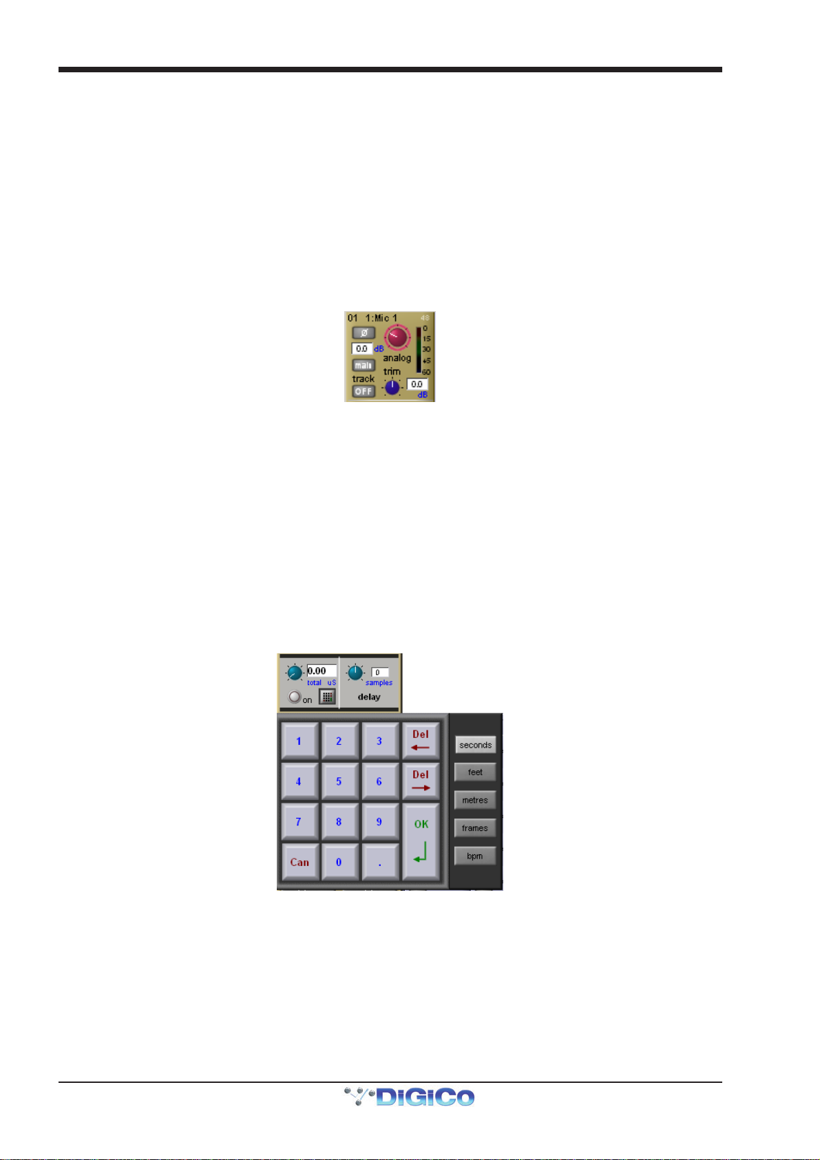
1.2.2 Channel Delays.....................................................................
Delay controls are found in the Setup display. The delay can be switched on using the on button, which is ringed in red to
indicate that it is on. The left-hand blue pot controls the course delay amount in milliseconds. The right-hand blue pot enables fine
adjustments to be made to this amount, measured in samples. Both pots can be assigned to encoders by touching the on screen
control.
It is also possible to enter a specific delay amount using a numeric keypad. To do this, touch the keypad symbol to the right of the
delay on button in the Setup display, select the desired units from the buttons to the right of the number buttons ( seconds, feet,
metres, frames or bpm) enter to amount using the keypad, and press OK.
Note that altering the delay units in this keypad display will change them wherever they appear on the
console.
1-2
Page 10
Chapter 1 - Channel Types
1.2.3 DiGiTube/Warmth .................................................................
The digitube area of the Channel Setup panel allows for the emulation of the non-linearities of a valve amplifier: At low levels the
valve is almost linear and at high levels the valve starts to compress and exhibits “soft clipping.”
Click the on button to activate. The number of times the tube can be activated is dependent on which SD console you are using.
Please refer to the Console comparison chart in the appendix for more information.
The drive control increases the gain into the valve and automatically reduces the output gain so that the volume stays the same
(like gain tracking); the indicator shows how hard you are driving the valve and hence how much distortion is being introduced.
The bias control sets the symmetry of the distortion: At 0 the distortion is symmetrical and produces largely 2nd harmonic (and
even) distortions; as the bias is increased, the distortion becomes more and more asymmetrical and starts adding 3rd (and odd)
harmonic distortions. In effect, the bias controls the characteristics of the distortion; a lower bias produces a softer distortion,
whereas as higher bias produces a harder distortion.
The warmth control (which is hidden if the on button is pressed) switches DIGItube on, sets it to its default settings, and hides
the rest of the controls. There is no limit to the number of times warmth can be switched on.
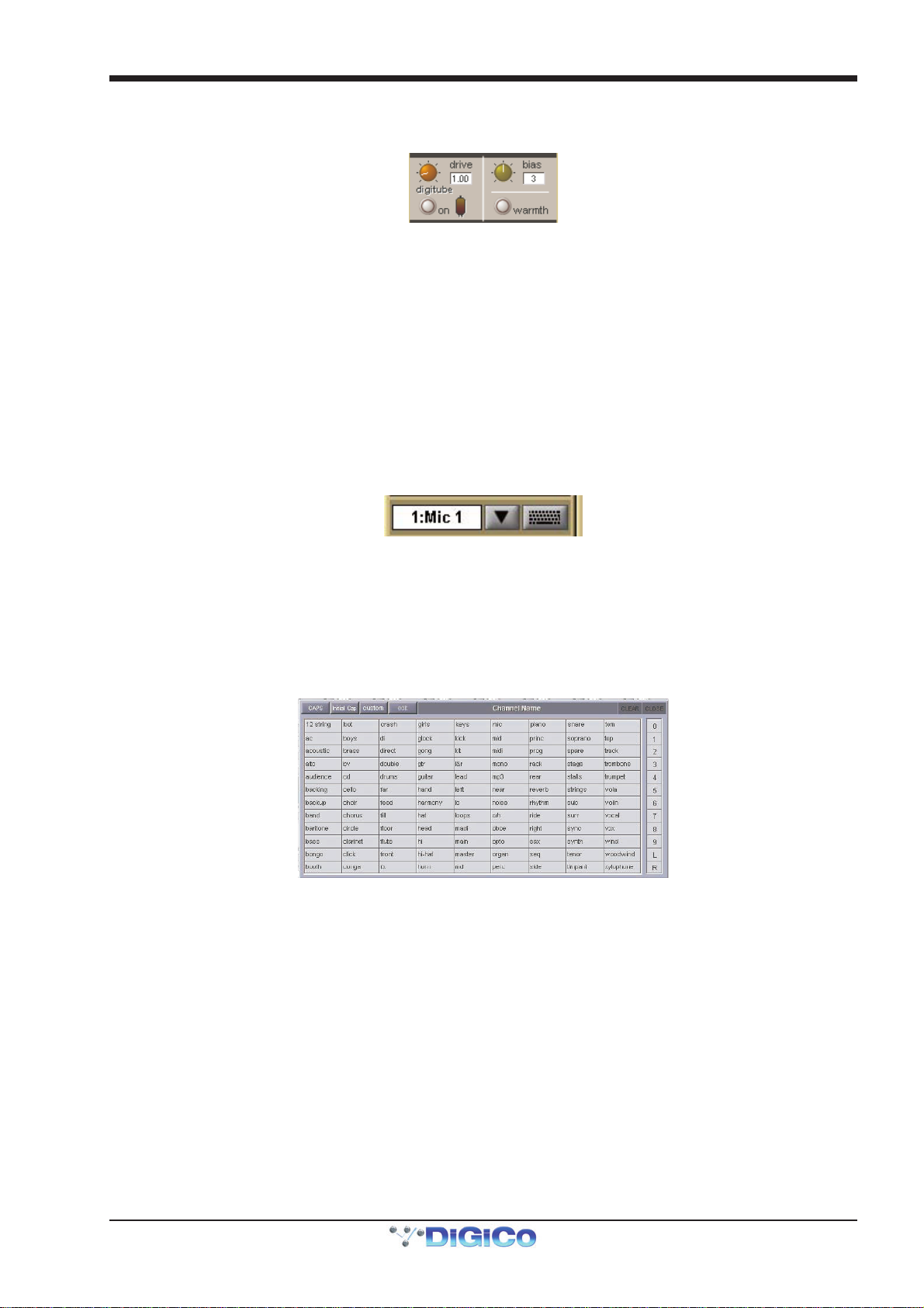
1.2.4 Naming Channels and Busses ............................................
A large number of elements within the console can be custom named. Access to the naming facility is via black and white text
boxes with down arrow and keyboard buttons to their right, such as shown here:
To create a name manually, touch the text box or the keyboard symbol to its right to bring up a QWERTY keyboard display. This keyboard includes standard Caps, Shift and Delete functions, as well as Cut, Copy and Paste functions which can be used to move name text between channels. The arrow buttons in the bottom left-hand corner of the keyboard display move the cursor within the text box. Create the new name, either using the on-screen keyboard display or the external keyboard, and press OK. To close the keyboard display without changing the name, press CAN. To move the keyboard display to the following channel, press Next (or TAB on the external keyboard).
The Channel Name display enables commonly used words to be inserted quickly without the use of the keyboard. This facility is available not only when naming channels but also when naming other elements. To open the Channel Name display, touch the down arrow immediately to the right of the Setup display’s channel name text box.
Touching any word from the display inserts that word into the channel name text box. Further words can then be added to the
channel name in the same way, divided by a single space. Numeric and L/R identifiers can be added from the column down the
right-hand edge of the display. Text can be entered in CAPS or Initial Caps by pressing the CAPS and Initial Cap buttons in the
top of the display. If neither of these are selected, all text is inserted in lower case.
Note that the first text to be inserted from the Channel Name display when it is opened overwrites all previous text.
Note also that text that extends beyond the end of the text box will not be visible!
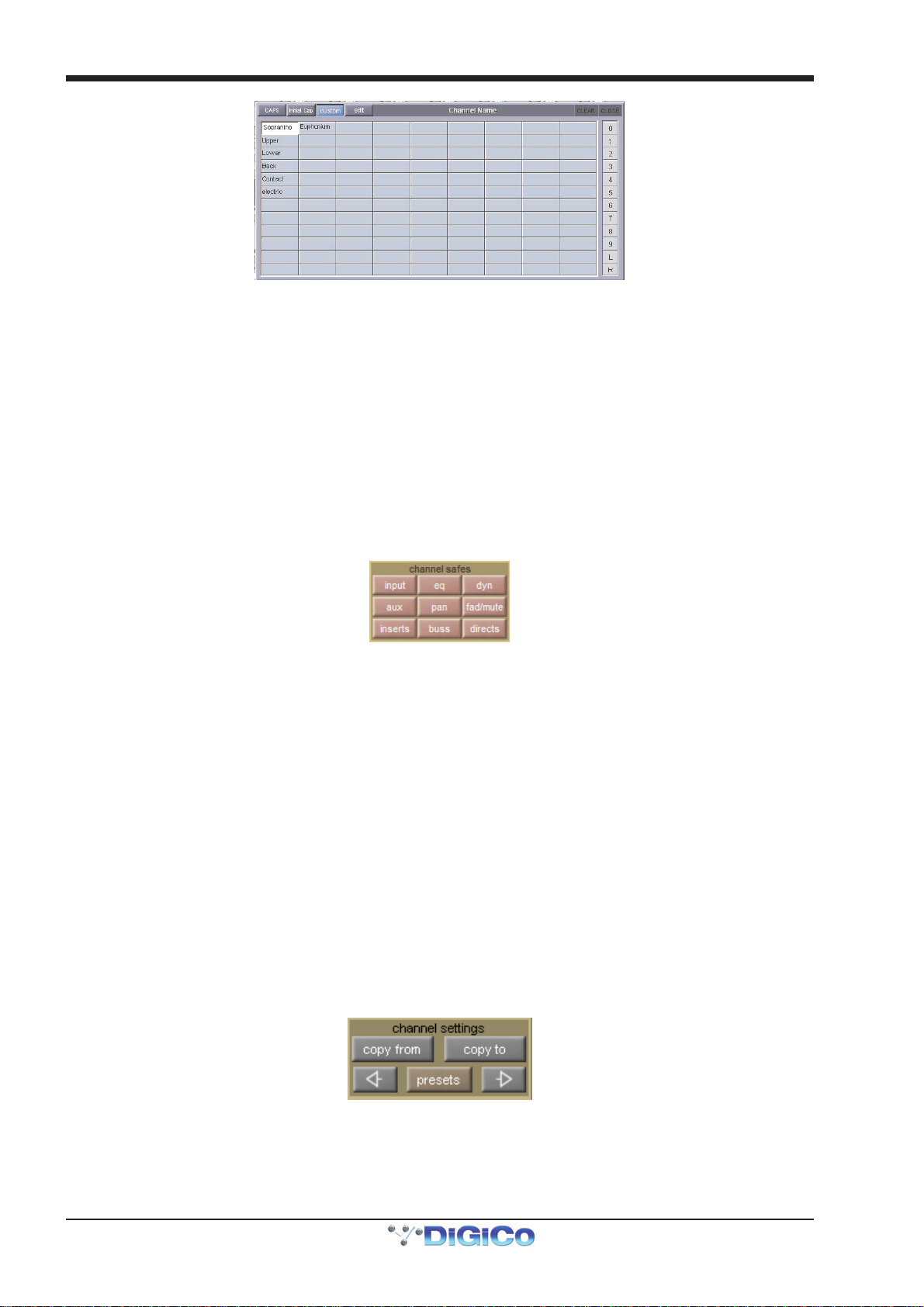
In addition to the standard word set, a list of user-defined words can be created and inserted by pressing the custom button,
located next to the Initial Cap button. The button lightens to indicate that the custom set is displayed.
1-3
Page 11
Chapter 1 - Channel Types
To add a new word to the custom set, touch the box which you want to use and press edit, located next to the custom button,
to bring up a QWERTY keyboard display. Type the required word and press OK. In this keyboard display, the Next button saves
any text inserted in the current box and moves the keyboard to the next box in the custom list. To cancel the keyboard display,
press CAN within the display, or press edit again. The words in the custom list are inserted into the channel name text box in
exactly the same way as words in the standard list. Pressing custom again returns the display to the standard word set.
Tip: As custom names appear in the box in which they are typed, they are not automatically alphabetised.
The user may find it helpful to define a system for ordering the custom page.
Note also that the standard word set cannot be edited.
The current name can be cleared by touching the CLEAR button towards the top right-hand corner of the Channel Name display. The Channel Name display can be closed by touching the CLOSE box, in the top right-hand corner.
1.2.5 Channel Safes.......................................................................
The Channel Safes area of the Setup display defines which parts of the channel will be not be affected when snapshots are recalled to this channel.
Note that the above diagram displays the Input channel safes. Output channels display a smaller list of
available channel safes.
Select whichever parts of the channel you want to protect in this way by touching the appropriate button. To cancel a safe, press
the relevant button again. The buttons turn red to indicate that they are safed. The presence of safes within the channel is also
indicated by the label of the appropriate channel part turning red and the background colour of that channel’s name also turning
red.
The EQ and dynamics settings can also be safed and unsafed from within the eq and dynamics displays. The whole channel can also be safed and unsafed by pressing the SAFE button at the bottom of on-screen channel (offline software), . It is grey to indicate that some elements of the channel are not safed, and red to indicate that the entire channel is safed.
Channel elements which have been safed are indicated by their text displaying red in the channel strip.
Tip: When some elements of the channel are safed, a double-press on the SAFE button can be used to quickly
clear all channel safes (SD5, SD7).
Note: Channel safes refer specifically to snapshot recalls and do not protect channel settings when using the
copy from, copy to and presets functions described below.
1.2.6 Copy Channels......................................................................
The Channel Settings area of the Setup display allow channel settings to be copied between channels. The left and right arrow
buttons are used to move the Setup display to adjacent channels.
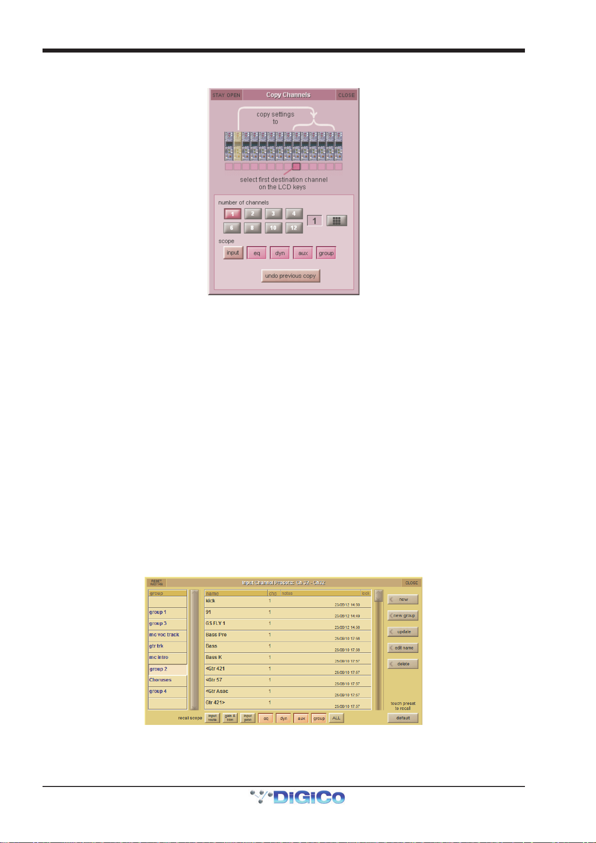
The copy from button allows settings to be copied from other channels to this channel and those to its right: Pressing copy from opens up a Copy Channels display:
1-4
Page 12
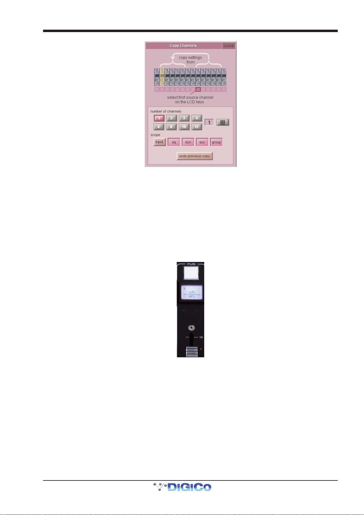
Chapter 1 - Channel Types
The extent of the channel settings to be copied is selected using the scope buttons towards the bottom of the display. Each
button lightens to indicate that it is included in the copy function. The number of source channels to be copied is defined either by
selecting the appropriate grey numbered button, or by selecting the keypad button to the right of the numbered buttons, typing the
required number of source channels into the numeric keypad which appears, and pressing OK. Press the LCD button (shown
below) on the left-most source channel in order to action the channel copy. If more than one source channel has been selected,
the settings of appropriate number of channels to the right of the source channel will copy to the channels to the right of the
destination channel (The current Assigned channel).
For example, to copy the EQ settings on channels 1-8 to channels 9-16 respectively:
- Make channel 9 the Assigned channel and touch copy from
- In the scope area of the Copy Channels display, select only the eq button
- Set the number of channels to be 8.
- Press the LCD/select button on channel 1.
1-5
Page 13
Chapter 1 - Channel Types
The copy to button allows settings to be copied from this channel to other channels: Pressing copy to opens up a Copy Chan-
nels display:
Note that this is a different Copy Channels display from that opened by the copy from button.
The extent of the channel settings to be copied is selected using the scope buttons towards the bottom of the display. Each
button lightens to indicate that it is included in the copy function. The number of destination channels to which this channel’s
settings will be copied is defined either by selecting the appropriate grey numbered button, or by selecting the button to the right
of the numbered buttons, typing the required number of source channels into the numeric keypad which appears, and pressing
OK. Press the LCD button (shown above) on the left-most destination channel in order to action the channel copy. If more than
one destination channel has been selected, the settings of the source channel will copy to the appropriate number of channels to
the right of the selected destination channel.
For example, to copy the EQ settings on channel 1 to channels 9-16:
- Make channel 1 the Assigned channel and touch copy to
- In the scope area of the Copy Channels display, select only the eq button
- Set the number of channels to be 8.
- Press the LCD/select button on channel 9.
If a copy from or copy to function is actioned by mistake, it can be undone by pressing the undo previous copy button in the
current Copy Channels display.
Tip: Use copy to for copying one channel’s settings to a number of other channels; Use copy from to copy the
settings of a group of channels to another group of channels.
1.2.7 Channel Presets....................................................................
Presets are used for storing and recalling settings for channels, fx units, graphic EQs and the matrix. While each preset functions
slightly differently, this section provides a basic understanding of how to use the various preset displays:
The left-hand column of a preset display contains the available groups of presets, and touching one of these groups brings up
the list of presets within that group in the column to its right (name). The columns to the right of the preset name displays the
number of channels whose settings are included in the preset (chs) (Channel and Matrix presets only), the date and time it was
created or updated (notes), and whether or not it is locked (lock).
Note that a presets display will only list presets of the relevant type.
1-6
Page 14

Chapter 1 - Channel Types
To recall a preset, touch the name of the group containing the preset you wish to recall, and then touch the preset’s name. The
recall scope buttons at the bottom of the some preset displays allow you to select which elements are recalled and which
elements remain unchanged. The buttons are included in the recall when they are lit.
To save the current settings as a new preset, touch the group in which you want the preset to be stored and press the new
button. The new preset is automatically named according to the preset type. To alter the preset’s name, type the new name using
the keyboard display that appears (or the external keyboard) then, if relevant, touch and edit the number of channels’ settings that
you want to store in the preset (the default is one channel). Now touch OK.
Note that pressing CAN in the keyboard display will cancel the display but create the new preset with its
default name.
To save the settings as an update of a previous preset, press update, touch the preset you wish to overwrite, and press Yes in
the confirmation display which appears.
Note that when updating a previous preset, failing to press update will result in the preset you wish to overwrite being recalled, and the settings to be saved being lost.
To create a new group of presets, press new group. A new group will be created, called group n, where n is the next available preset group number. To alter the group’s name, type the new name using the keyboard display that appears (or the external keyboard) and touch OK.
Note that pressing CAN in the keyboard display will cancel the display but create the new group with its
default name.
The edit name button allows preset names and group names to be edited, and the preset to be locked, preventing them from
being edited, overwritten, or deleted. The button lightens to indicate that it is active. To edit a preset’s name, make sure the preset
is unlocked (see below), activate the edit name button and touch the preset’s name. Type the new name in the keyboard display
and press OK. To edit a preset group name, activate the edit name button and touch the group name. Type the new name in the
keyboard display and press OK.
To lock the preset, activate the edit name button and touch the preset’s lock column. A grey padlock appears, indicating that the preset is now locked. Touching the lock again with edit name active unlocks the preset.
To delete a preset, press delete, touch the preset to be deleted, and press confirm. To delete a consecutive range of presets,
press delete followed by select range, touch the first and last preset to be deleted and press confirm. To delete one preset,
or a nonconsecutive range, touch each preset to be deleted and press confirm. To delete an entire group of presets, press
delete followed by select all, then press confirm.
1.2.8 Channel Solos.......................................................................
SD consoles have two solo busses, and each channel can be assigned to solo 1, solo 2 or both solo 1 and 2. If the console was being used for Stage monitors, this would allow, for example, the first solo buss to feed In-Ear monitors and the second solo buss to feed a wedge.
Note: The solo busses are configured in the master solo displays, accessed by pressing the Solos button at
the top of the Master Screen.
The channel’s solo routing is assigned in the section at the bottom section of the channel Setup display. Pressing the green solo 1 and solo 2 buttons enables the channel to be routed to solo busses 1 and 2 respectively. The buttons are green to indicate that the solo buss is available, and grey to indicate that it isn’t.
Note that each channel must be enabled for at least one solo buss.
When the blue auto solo buttons are active (indicated by white, rather than grey, text), that channel is automatically routed to that solo buss whenever another channel is soloed to that buss.
Note that a list of channels with auto solo enabled is displayed in the auto solo section of the master solo
display. The auto solo function has to be activated by pressing the blue enabled button below the auto solo
list in the master solo display. Auto solo is disabled when in single solo mode.
Tip: If you are using effects returns, selecting auto solo can allow soloed tracks to be auditioned with their
effects returns.
1-7
Page 15
Chapter 1 - Channel Types
1.3 Channel Output and Inserts - Common Elements
1.3.1 Channel Strip Output Area...................................................
The channel strip output area makes up the lower half of the Channel Strip panel (shown below for an input channel). This is
where the channel output routes are configured (including Aux outputs in the case of Input channels).
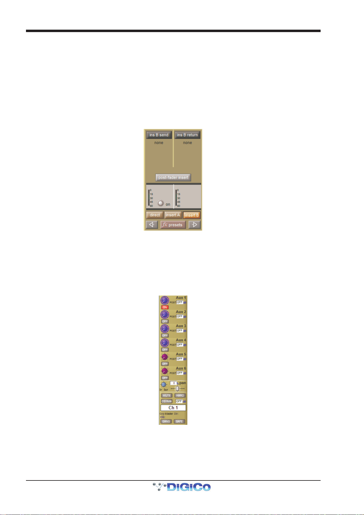
Each channel also has two inserts: insert A and insert B. Both inserts follow the format (mono or stereo) of their channel. The channel strip insert areas are located above the eq section (insert A) and below the 2nd Dynamics section (insert B), and their signals are sent and returned to that position within the signal path: insert A is pre-signal processing (but post filters), and
insert B is post signal-processing. Only one point, either insert A or insert B, can be used per channel on SD9 or SD11.
Post-Fade Inserts
Up to 32 mono input channels can have their insert B point switched to a post fader insert point using the button in the Output
Setup panel.
Note that Multi channels do not have their own insert controls – each multi-channel component's insert
points are configured individually.
Some basic output and insert functions are found in the channel strip. However, most of the output and insert parameters are
contained in the channel Output display, accessed by touching the channel’s output or insert areas.
Note that on Input channels, an aux display is opened by touching the aux area. To open the Output display,
touch in the muting and naming area below the pan control.
Note that if there are any multi-channel busses in the Session Structure, the pan display will be different
from that shown above.
1-8
Page 16
Chapter 1 - Channel Types
For all output channel types, there is a channel meter displayed in the channel strip. For Input channels, this part of the channel
strip contains the aux outputs, as shown above. On stereo and multi-channel format channels, symbols below each meter
indicates which component is displayed. LFE channels are indicated by a small box with a dot in it.
Note that input channels can display a meter in the top section of the channel strip.
Meter sources are defined in the Options menu, described in the Master Section
Below the meters section of output channels, there is an fx output button. This button brings up either the controller display for the effects preset that has been assigned, or the fx Presets display if no preset has been assigned.
Note that below the aux section of an Input channel, there is a pan control in place of the fx output button.
When an effects preset has been assigned to that channel's Direct Out, touching this pan control brings up
the FX preset controller display.
Towards the bottom of the channel strip there is a scribble strip text box displaying the channel names.
Note that the channel naming facility is found in both the channel Setup and Outputs displays.
Below the channel name, there is indication of the lowest group (Grp:) output (along with indication of the lowest direct output
(Dir:) in the case of Input channels), and indication of any control group (CG:) to which the channel belongs.
The on-screen channel has MUTE and HARD indicators located above the scribble strip. Pressing the worksurface MUTE button (above the LCD button) silences all outputs from the channel apart from any which have been assigned pre-mute (this option is available for auxes and direct outs). Pressing the worksurface 2nd Function button to activate the HARD mute silences all outputs from the channel, including those which are assigned pre-mute. A dedicated HARD mute button can be found on both SD5 and SD7 worksurfaces.
Immediately below the HARD button, there is a numeric display of the channel’s main fader value in dB. Below the MUTE button there is a CG MUTE Indicator which shows when the channel is muted as the result of its membership of a muted Control
Group. At in the bottom left-hand corner of the channel strip, there is a GANG display. To the right of the GANG button there is a SAFE button. This indicates that one or more of the channel's recall safes have been activated.
1.3.2 Channel Strip Insert Areas...................................................
Channel strip insert areas include a button for switching that insert send on and off. The button is grey when the send is off, and
red when it is on.
Below the on/off button, there is a display of the current insert routing. The send route is displayed on the left, prefixed by S:, and
the return route is displayed on the right, prefixed by R:. If no routing has been selected, these areas are blank apart from these
prefixes. If the channel is stereo, only the left side of the insert routing is displayed.
1.3.3 Console Output and Insert Routing .....................................
The Output displays for all channel types allow direct routing either to the external IO racks, or to one of a variety of internal
locations, for both the channel’s main output (or direct output in the case of Input channels), and its insert send and return.
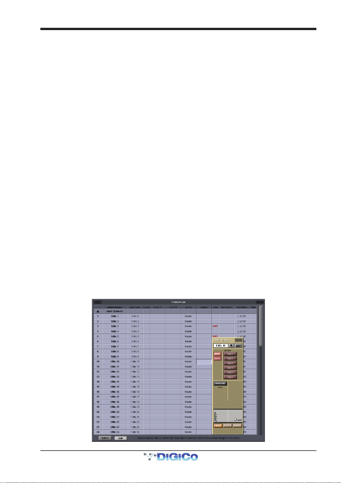
In addition to touching inside the output area of the channel strip, it is also possible to open each channel's Outputs display from
the Channel Lists display, opened from the Master Screen's Layout menu: Activate the Edit button at the base of the display,
expand the required channel type by touching its entry in the list, then touch the output column within the required channel row.
An outputs display will open within the Master Screen:
1-9
Page 17
Chapter 1 - Channel Types
Towards the bottom of the Outputs display, there are three buttons marked output (direct in Input channels), insert A and
insert B. Selecting one of these buttons assigns that send (or send and return) to the signal routing area above it: When either
insert is assigned, the ins A send or ins B send routing button appears in the left-hand column, and the ins A return or ins B
return routing button in the right-hand column; When the output (direct output in Input channels) is assigned, the outputs (direct
outs in Input channels) routing button appears in the left-hand column and the right-hand column is left blank. Pressing any of
these routing buttons opens a routing display.
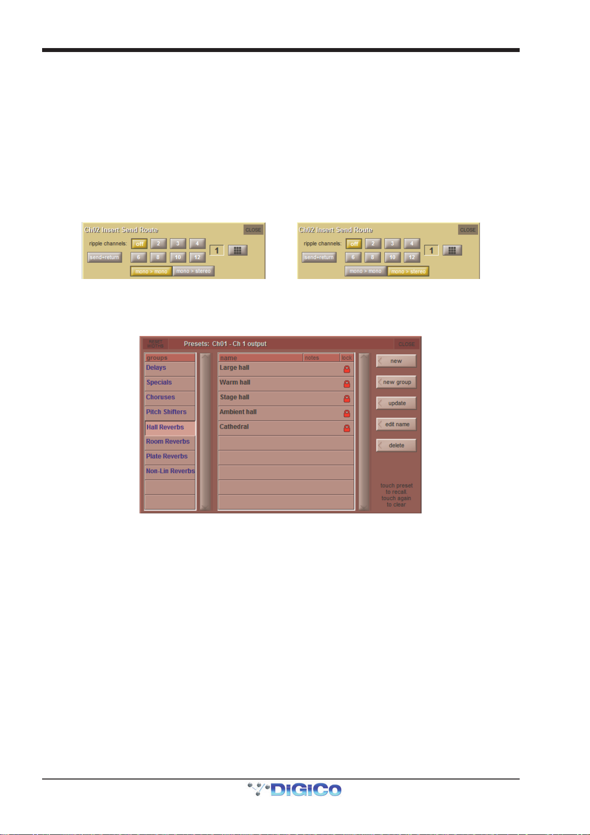
An extra button labelled send+return is included above the ports list in the Insert Send Route display button. When this button is activated, the send and return routing is linked for all signals within the INTERNAL port: If the Graphic 1 input is assigned to the insert send, the Graphic 1 output is automatically assigned to that insert return. Similarly, if it is the return which is manually assigned, the send automatically copies that send assignment. The send+return button is grey when inactive and brown when active.
The mono > mono and mono > stereo buttons are used when routing a mono channel to internal fx units and Waves plug-ins
(where available). When mono > mono is selected, the channel signal is routed to left side of an fx unit, or to a mono Waves
rack input. When mono > stereo is selected, the channel is routed to both sides of the fx unit or Waves rack.
1.3.4 FX Presets .............................................................................
Each channel output or insert send can be sent to an internal FX Unit. Pressing the fx presets button at the bottom of the Outputs display brings up the fx Presets display. The fx preset is applied to whichever channel output is active in the Outputs display when the fx presets button is pressed: the main channel output (or direct output), insert send A or insert send B:
Note that column widths can be adjusted by dragging their borders within the title row. To return all columns to their default widths, press RESET WIDTHS, in the top left-hand corner of the window.
For more details of SD FX and FX preset management, please refer to the Master Section Chapter
1.4 Input Channel Specific Functions
1.4.1 Trim and Track......................................................................
On Input channels which a mic or line input, there is a trim section at the bottom of the channel strip’s input area, consisting of a smaller pot marked trim and a track on/off button. The trim pot digitally trims the level of the input signal, and the level adjustment is displayed to the right of the pot in dB. If track is switched on, the trim level automatically compensates for any adjustments made to the analogue input level: If the analogue input level is increased, the trim level will decrease in order to keep the signal level coming through the channel at the same level. This function is particularly useful when the analogue level is being controlled from another console, such as when this console is running monitor mixes and another console is running Front of House. Control of the trim pot and track on/off button can be assigned to the encoder and button above/below the channel using the assign scrollers to the left of the encoders or the quick select buttons.
Relative Gain-Tracking - Snapshot Recalls Total Gain
“Relative Gain-Tracking” is implemented as a “Snapshot Recalls Total Gain” option at the bottom of the Snapshot Global Scope
panel. When a snapshot recalls an input channel trim, it compares the snapshot’s stored analogue gain against the current gain
on the channel’s input socket. If there’s a difference it offsets the value recalled by the trim. This only happens when the
socket’s rack is in Receive Only, or the analog gain is not in Recall Scope.
1-10
Page 18
Chapter 1 - Channel Types
1.4.2 Input Routing.........................................................................
Inputs are routed using the channel Setup display, opened by touching in the input area of the channel strip. It is also possible to
open the display from the Channel List display, opened from the Master Screen's Layout menu: Activate the Edit button at the
base of the display, expand the required channel type by touching its entry in the list, then touch the output column within the
required channel row. A Setup display will open within the Master Screen:
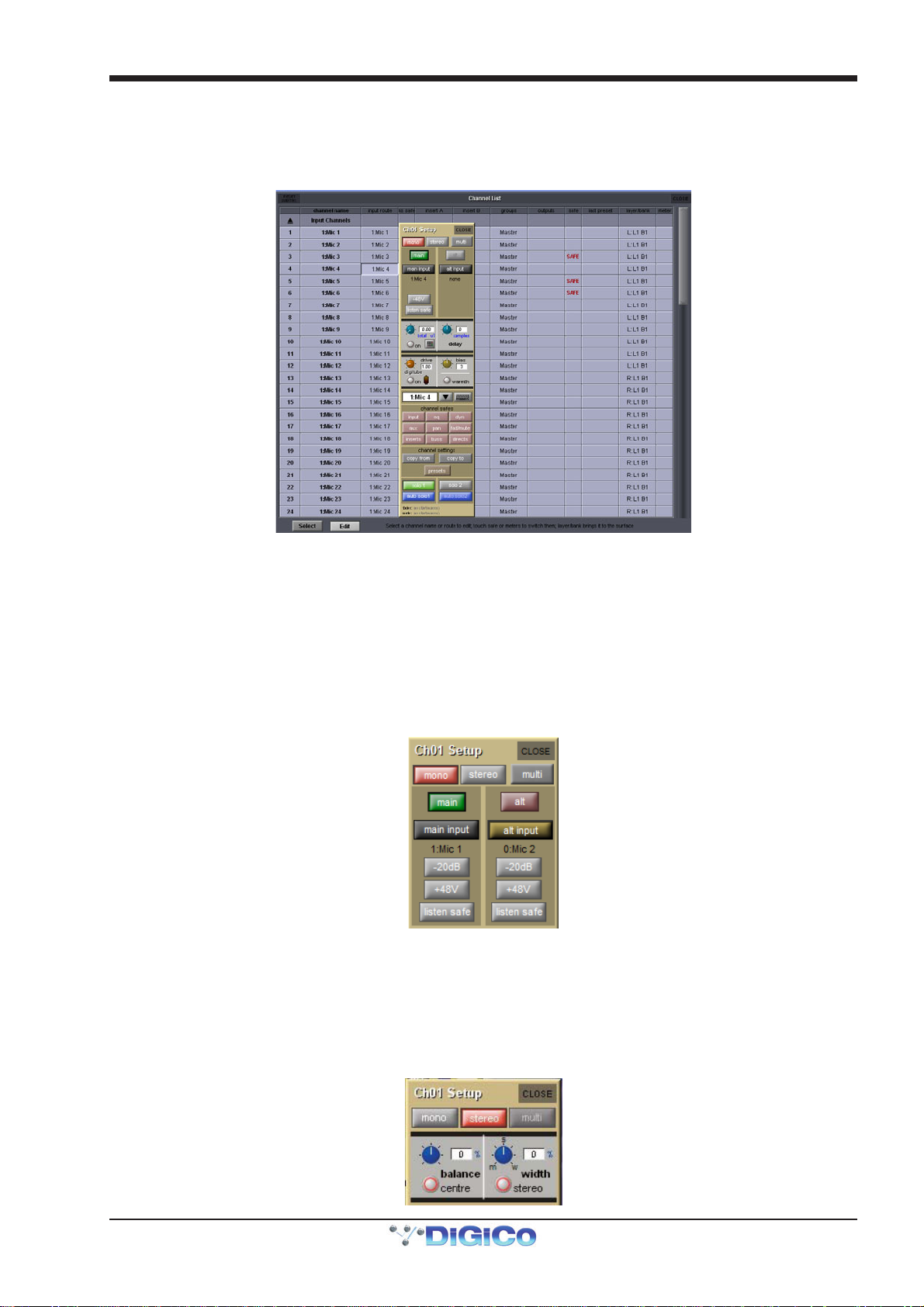
The buttons at the top of the channel Setup display to define the format of the channel: mono or stereo.
Note that Multi-channel formats are configured in a different way from mono and stereo formats, as described later in this chapter
As the channel format affects a number of functions within the Setup display, it is advisable to select the format before any
further configuration takes place. The current format of the channel is indicated in the channel strip by the number of meters
displayed: One meter for mono channels and two for stereo.
For mono channels, each input channel has two inputs: a main input and an alt(ernative) input. These are selected using the main button in the channel strip. The button is grey when the main input is selected and red when the alt input is selected. The input can also be selected using the main and alt buttons towards the top of the Setup display. These buttons light to indicate which one is currently selected. For stereo channels, the alternative input becomes the right side of the stereo input, and therefore no main and alt input selection buttons are shown.
The inputs available on an Input channel include feeds from the external IO racks, the local inputs on the back of the console and a
variety of internal signals. Pressing either the main input or alt input routing button in the Setup display opens the Input Route
display. The signal feeding each input can then be selected as described in the Getting Started section of this manual.
1.4.3 Input Configuration...............................................................
If a channel is stereo, balance and width controls appear below the mono and stereo buttons: The left-hand blue pot controls the balance and can be reset to centre by pressing the centre button below it. The right-hand blue pot effects the width of the stereo signal, with a range from mono to wide. The width can be reset to stereo be pressing the stereo button beneath the width pot. The value of the balance and width is displayed to the right of each pot as a percentage divergence.
1-11
Page 19
Chapter 1 - Channel Types
Stereo channels also have an m-s button, located above the input routing button, which switches in a decode function for replaying M-S signals as a normal stereo pair. There are three further buttons in this panel: L<>R swaps the channel’s left and right outputs, L>L+R sends the left signal to both left and right busses, and R>L+R sends the right signal to both left and right busses.
1.4.4 Channel Metering .................................................................
Channel meters can be displayed in the top section of the Input channel strip, in place of the input and filters areas. To do this,
press the meter (SD7, SD5), rotary assign (SD8, SD10), screen scroll (SD9, SD11) up button, located on the console
worksurface. If these encoders are initially assigned to the trim function, you will need to press the rotary assign up button
twice to display the meters.
If you adjust any parameter which is hidden by the meters, the meters will be hidden momentarily, allowing adjustments to be
viewed.
1.4.5 Output Routing.....................................................................
Signals can be fed from Input channels to four different places: aux busses, group busses, insert sends and direct outputs. Insert
routing and basic direct output routing are described in the Getting Started Manual.
The top half of the output section of the Input channel strip contains the aux buss controls, as previous described. Below the
auxes, there is a pan control, affecting the relative levels of the channel’s left and right outputs to any stereo routing destinations.
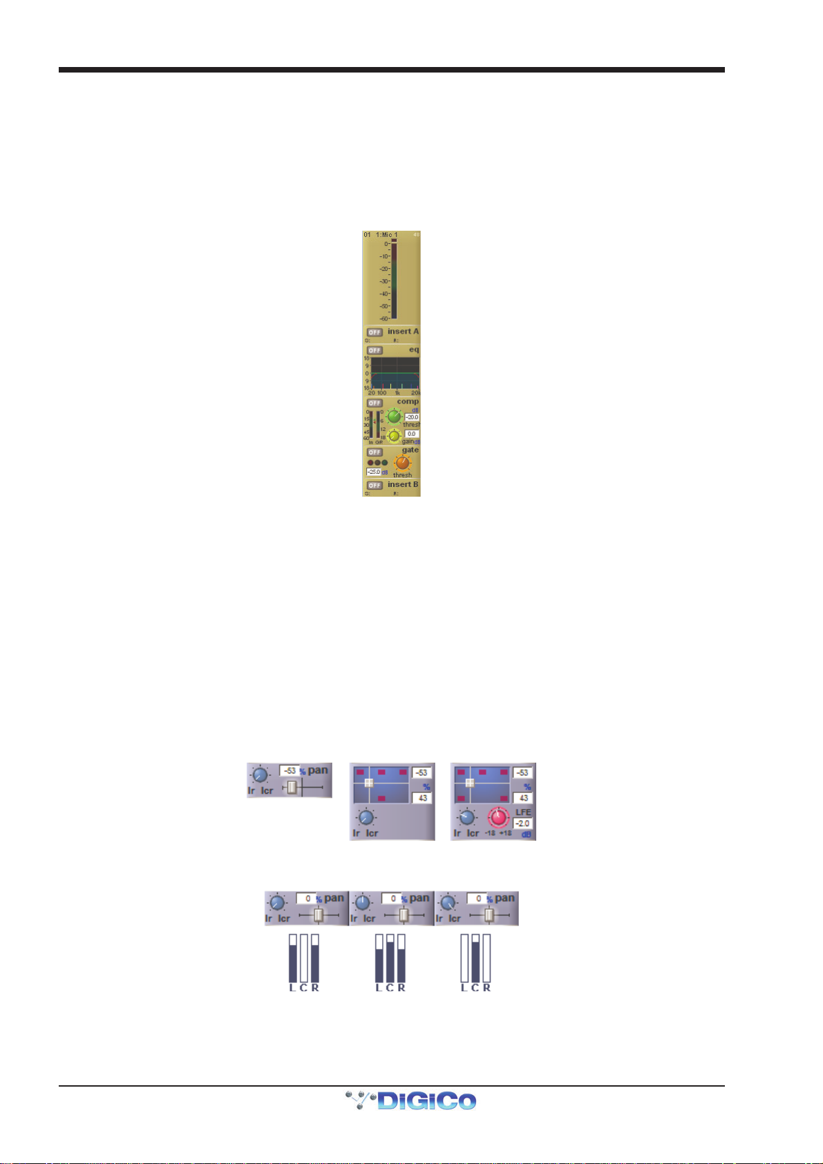
The controls are formatted to match the format of the buss with the most components:
- Where there are only stereo or LCR busses, a simple pan slider is shown (see below left). Move the slider to adjust the
pan. A text box indicates the panning position as a percentage from the centre towards the right.
- Where there are LCRS busses, a two-dimensional panning scope is shown (see below centre). Move the central grey
square to adjust the position. Text boxes indicate the left-right and front-back position.
- Where there are 5.1 busses, a two-dimensional panning scope is shown, along with a pink LFE level control (see below
right). Move the central grey square to adjust the position. Text boxes indicate the left-right and front-back position, as
well as the LFE gain.
There is also an LR/LCR Blend control. This control allows adjustment of the amount of signal that is sent to the centre leg (where one exists) of a surround buss. In the extreme left LR position, no signal will go to the centre leg:
The pan of the Assigned channel can be controlled using the worksurface joystick (SD5,7,8,10). The pan control can also be
assigned to one of the encoder rows. LR/LCR Blend is adjusted using the 2nd function button.
1-12
Page 20
Chapter 1 - Channel Types
1.4.6 Aux Busses and Assignable Controls ..................................
Within an Input channel strip, each aux send has a level trim and on/off switch to the right. The switch is grey to indicate that the
send is off, and red to indicate that it is on. The trim level is displayed in dB on the right of the channel strip, underneath the aux
number.
There are three places within the channel from which the aux sends can be fed, as indicated by the source display immediately to
the right of the level trim:
PRE Pre-fader
POST Post-fader
Pre-M Pre-mute (and pre-fader)
The source position can be changed by pressing the worksurface 2nd function button and using the switches below the aux
send encoders. The source for each aux can also be adjusted globally via the aux channel’s Setup display.
On stereo aux sends, there is a pan control to the right of the on/off switch. This can be adjusted by pressing the worksurface
2nd function button and using the rows of encoders below the worksurface screen. The pan controls for each aux can be
globally linked to the channel fader via the aux channel’s Setup display.
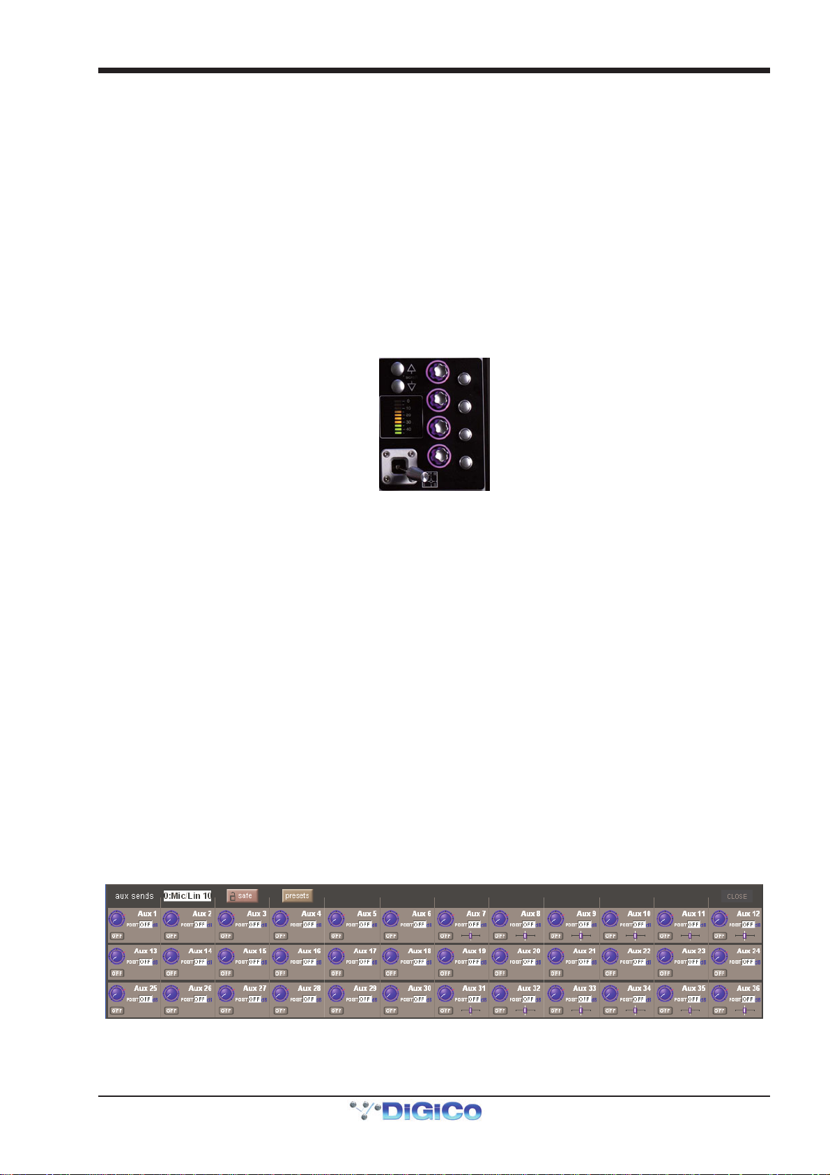
At the bottom of the assigned channel SD7 worksurface controls, there are four dedicated aux encoders with buttons, which
control four contiguous aux send pots and on/off switches for the Assigned channel:
The auxes controlled by these encoders and buttons can be selected using the scroll buttons to the left of the top encoder, and is
indicated by purple ring on the on-screen aux sends.
Note that this assignment is channel specific and will be recalled if the Assigned channel is changed and
returned to that channel.
The encoders and buttons immediately below the Channel Strip can be used to control either the aux sends, or a separate
function. This function is referred to as the ‘locked’ function, as it does not change when the auxes are moved. The button at the
end of each row, next to the LCD display, flips the assignment of that row between the aux sends and the locked function.
Touching any on-screen aux send assigns the highest available encoder row to that send, and assigns any other available
encoder rows to the aux sends below it. The scroll button outside the bottom left-hand corner of the screen can also be used to
change which auxes are assigned to the encoders. (SD5,7,8,10)
Note that only six auxes can be displayed in the Channel Strip panel at once. The panel will always display
the auxes assigned to the encoder rows below it. This means that the auxes controlled by the dedicated aux
encoders in the channel worksurface controls may not be visible.
By default, the encoders control the aux level and the button controls the aux on/off status. However, by pressing the 2nd
function button (located on the surface), the button becomes the aux’s source selector (toggling between PRE, POST or Pre-M),
and the encoder becomes the pan control of a stereo channel. On mono auxes, the encoder has no second function.
It is also possible to show all of the aux sends for a channel in a single display and assign them to the rotaries beneath the
screen. This is done by assigning the required channel to the aux controls (the assigned auxes will be displayed in dark purple
with a dark purple surround) then touching one of the assigned auxes. The layout of the display indicates which encoder each
aux is assigned to; if there are more sends than rotaries, the assignments becomes scrollable using the Screen Scroll function.
The Picture below shows an SD7 with 36 Sends.
Once you have adjusted the auxes in this display, you need to close it manually before opening any other channel detail display.
Note that further worksurface assignments of auxes is available via the Surface, Faders and Solo tabs of the
Options menu.
1-13
Page 21
Chapter 1 - Channel Types
1.4.7 Group Outputs .......................................................................
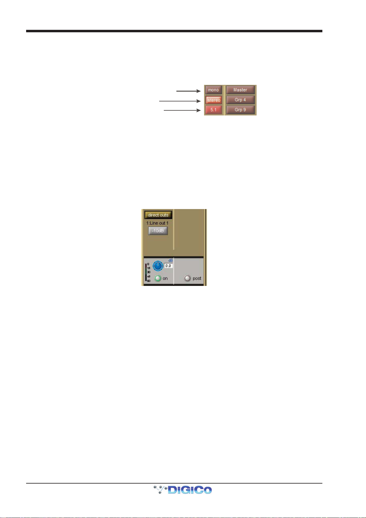
Group outputs are routed from within the groups section of the channel Outputs display. Touching the mono button to the left
of the display produces a list of available mono groups in the right of the display, and touching the stereo or surround format
buttons produces a list of the other types of group. These buttons 'light' to indicate that it is their group outputs list which is
currently displayed, and 'half-light' to indicate that there is routing to busses of that format which isn't shown in the display.
Touching any of the groups within each list routes the channel to that group. Each channel can be routed to as many mono and
stereo groups as have been created.
Unlit: mono routing inactive and not shown
Lit: stereo groups shown to right
Half lit: 5.1 routing active but hi dden
Any mono groups being fed by a stereo channel will receive a L+R summed signal of the channel output.
The lowest selected group output is displayed in the channel strip, below the left side of the channel name, and the currently
selected direct output is displayed below the right side of the channel name.
When a new session is created, the lowest numbered stereo group is always designated the Master. Therefore, all input
channels are routed to it by default, and the master fader(s) are assigned to it.
1.4.8 Direct Outputs .......................................................................
Basic routing is described in your console's Getting Started section. Once the direct output has been routed, it is switched on by
pressing the grey on button next to the output level meter in the grey area below the direct outs routing button. The direct out is
taken post-fader by default, but can be switched to pre-fader or pre mute by pressing the button to the right of the on button. The
current selection is displayed to the right of the button.
1.5 Output Channels Specific Functions
1.5.1 Unfolding Channels ..............................................................
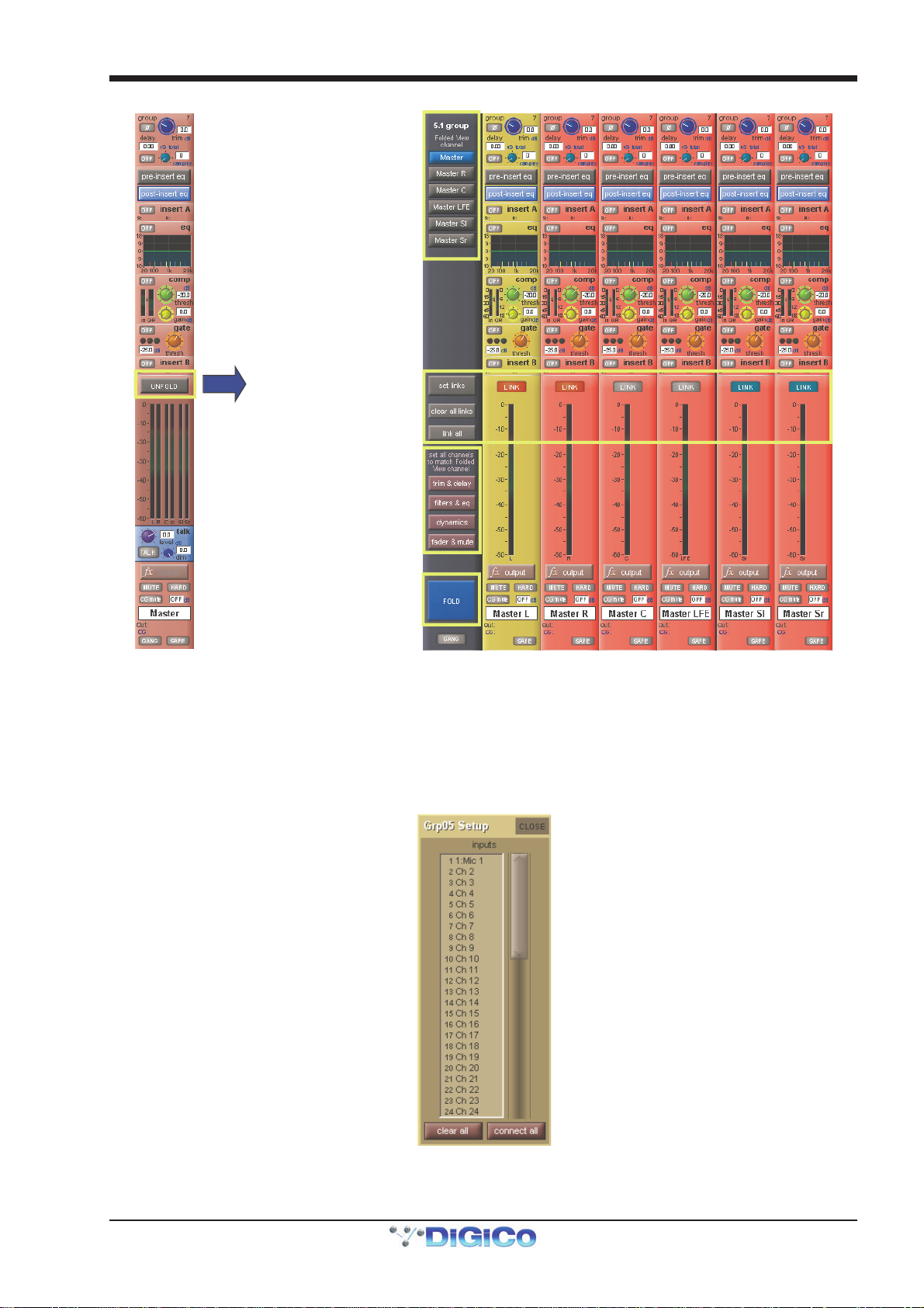
Group and Aux Channels which are stereo or surround have an Unfold button above their meters, which is used to display the
components of the signal in their own channel strip with a master channel displayed to their left.
In the top section of the unfolded Master channel, buttons for each component channel allow you to define which channel's
elements are displayed in the Folded View.
In the middle area of the unfolded Master channel, the links between component channels can be edited. Links function in the same way as Gangs, but are limited to the components of a multi-channel signals. To edit links, press the Set Links button so that it goes red, then press the LINK buttons above the channel meters in the channels to be linked or unlinked - each button will take on the same colour, indicating that they are linked. To remove a link, press the LINK button while Set Links is active. Note that if you start a set of links and then de-link and re-link another channel, a new link set will be started, as indicated by the introduction of a new link colour. When you have finished linking channels, deselect Set Links. You can also clear all links and link all using the buttons below Set Links.
Note that if component channels have different settings when linked, changes in hidden, linked channels will
be made relative to the change in the Folded View channel, but the display will only reflect the Folded View
channel.
Below the link buttons in the master, there are buttons for each element in the components' channels - trim & delay, filters &
eq, dynamics and faders & mutes. Pressing one of these buttons will cause that element in all the channels to match those of
the Folded channel. Once you have finished with the unfolded view, press the FOLD button to fold the channels back together. The picture below
shows a 5.1 Buss from an SD5/SD7
1-14
Page 22
Folded View
Channel
Chapter 1 - Channel Types
Unfold
Links
Settings
Fold
1.5.2 Group Channels Specific Functions....................................
The Group channel input signals are defined within the Input channels Output display. The top section of the Group channel
Setup display lists all of the currently selected inputs to that group. The inputs list can be scrolled using the scroll bar to the right
if necessary. Below the list there are two buttons: clear all removes all of the input routes to that group. Pressing this button produces a confirmation box in which the clear all can be confirmed or cancelled. connect all routes all Input channels to the group.
Note: With either the connect or clear all functions, you can exclude individual channels from the function
by touching their faders when the button is pressed.
Group channel output routing functions are very much like Input channel output routing.
1-15
Page 23
Chapter 1 - Channel Types
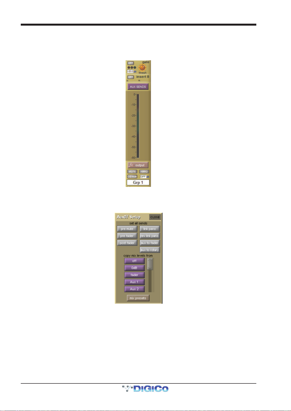
Aux Sends on Groups
Group output Busses can send audio to Aux output busses. Pressing the Aux send button, located above the output meter, will
open the expanded aux panel and the sends will be assigned to the under screen rotaries.
To access the aux sends for a stereo, LCR, LCRS or 5.1 Group, the Buss must be unfolded to show the individual legs, each leg
having it’s own aux send levels.
1.5.3 Aux Channels Specific Functions........................................
As the Aux channel input signals are defined within the Input channels, there is no input selection available within the Aux channel
Setup display. There are, however, a number of configuration options in the top half of the Setup display:
The set all sends buttons at the top of the Setup display affect the sends to that aux bus from all of the Input channels.
The three buttons on the left, pre mute, pre fader and post fader, set the point in the channel from which the aux send is
taken. The current send point is displayed next to the aux send level in the Input channels.
Note that send points can also be individually selected within the Input channel using the 2nd function
button.
Pressing the link pans button, located to the right of the pre mute button, links that aux send pan to the main channel pan in the Input channels. This button lights red to indicate that it is active. Further indication is provided by the aux pan slider in the Input channel strip being lit pink. Rev link pans inverts the link between the channel pan and aux send pan.
Pressing aux to fader assigns control of all input channel’s auxiliary sends to the channel faders.
1-16
Page 24
Chapter 1 - Channel Types
Pressing aux to rotary assigns control of all input channel’s auxiliary sends to the top available encoder row beneath the Channel Strip panel.
The purple copy levels from buttons also affect the sends to that aux bus from all of the Input channels. The buttons list can be scrolled using the scroll bar on the right. These buttons are used for universally setting the aux send levels:
Off sets the level to off and 0dB to 0db. fader sets each Input channel’s aux send level to match the level of its channel fader.
The remaining copy levels from buttons copy a different set of Input channel aux send levels to that aux send.
Note that when a copy levels from button has been pressed, send levels can still be individually readjusted
within the Input channel.
Touching the mix presets button (below the copy mix levels from list) opens the Aux Mix Presets display, where you can store and recall presets of an aux send's parameters for all input channels, using the standard presets procedure, detailed in Section 2.
1.5.4 Matrix Channels Specific Functions....................................
As the Matrix channel input signals are defined within the Matrix inputs display, there is no input selection available within the
Matrix channel.
1.6 Channel Signal Processing
Each channel type contains similar signal processing functions, including EQ and dynamics. Input channels also have high-pass
and low-pass filters. Pressing on each of these areas of the channel strip will open the relevant signal-processing display.
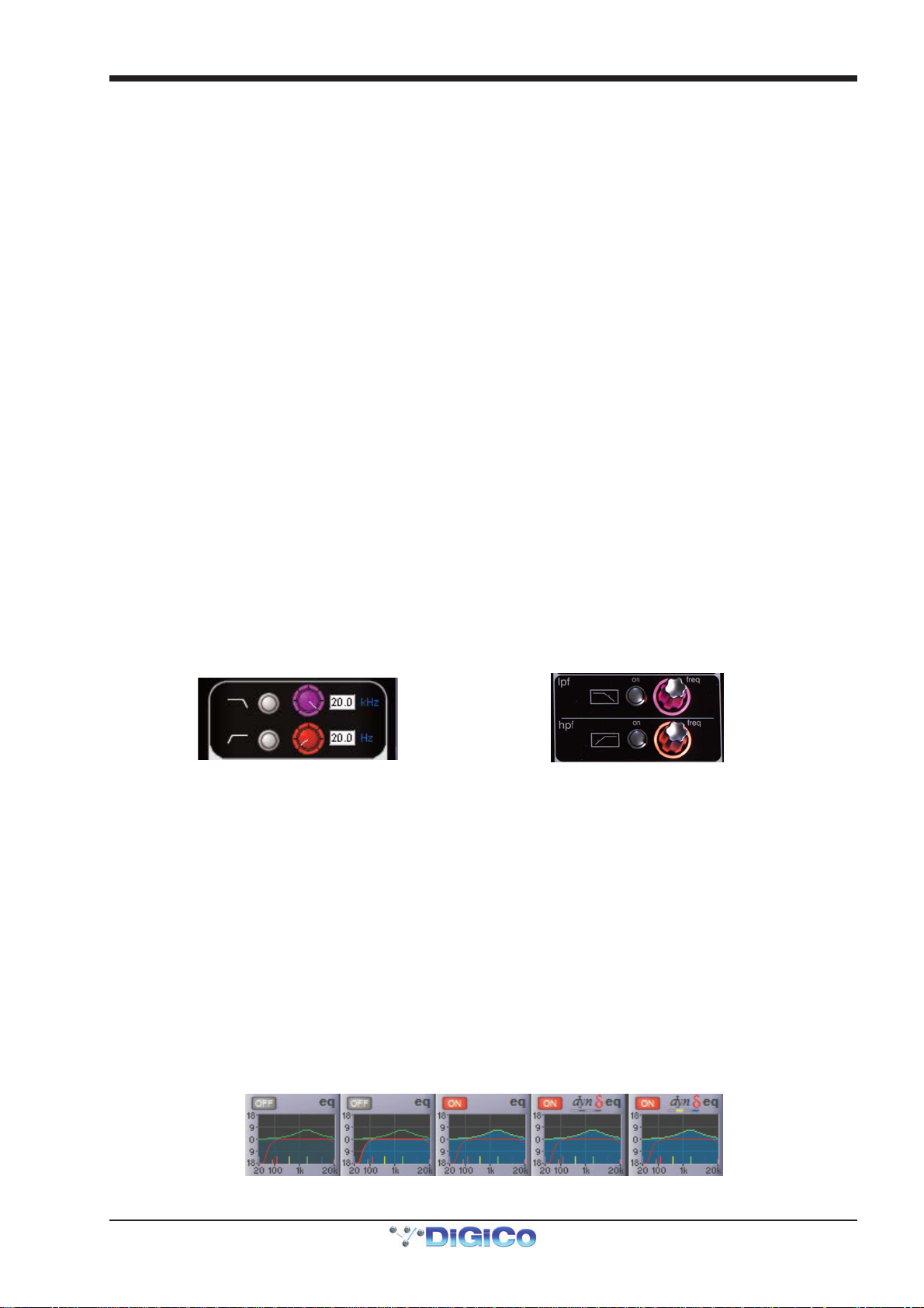
1.6.1 Channel Filters......................................................................
(All SD input channels and on SD8,9,11 output channels)
The filters section of the channel-strip is located below the input section of each input channel. It consists of two frequency pots,
each with its own on/off button and a display of the filter’s cutoff frequency (the -3dB value) in Hertz. The on/off buttons are grey
to indicate that the frequency band is off, and red to indicate that it is on. The low-pass filter is at the top and the high-pass filter is
at the bottom, and both have a roll-off of 24dB per octave. The filters directly follow the input section in the signal chain.
The filters area is replicated at the top of the EQ/filters display, accessed by touching the EQ area of the channel strip. The filter
can be configured using the dedicated filter encoders and buttons at the top of the channel worksurface controls:
A graphic representation of the filters is included in the EQ graph located below Insert A in the channel strip, described below.
The red line in the graph represents the current filter settings.
Note that the filters section of the input channel strip may be hidden behind channel meters. In this case,
moving the filter encoders will cause them to be displayed momentarily. To hide the meters and retain a
permanent display of the filter controls, press the assign down button, located to the left of the encoders
above the screen.
1.6.2 Input Channel EQ..................................................................
The SD input channel EQ has four bands, each of which can be made dynamic. The four EQ bands are colour coded: Blue for HF,
green for HMF, yellow for LMF and red for LF. The in-channel display is located below Insert A and consists of a graphic
representation of the current EQ and an on/off button. The button is grey to indicate that the EQ is off, and red to indicate that it is
on. The green line in the graph represents the frequency response of the EQ, and the red line represents the response of the
filters – each line goes bright to indicate that it is on. The extent and brightness of the clouded area in the bottom half of the graph
also indicates which elements are on. The central frequency of each band is displayed by small lines in the band colours, along
the bottom of the graph.
EQ and filters
both off
EQ off,
filters on
EQ on,
Filters off
Dynamic EQ on
bands 2+4, with
both bands off
Dynamic EQ on
band 2+4, with
both bands on
1-17
Page 25
Chapter 1 - Channel Types
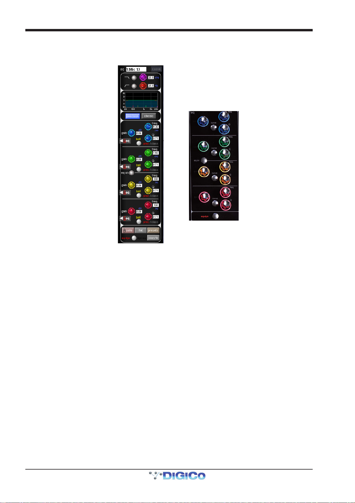
Touching the EQ area of the channel strip brings up the EQ/filters display. The EQ section of the display is below the filters
section, and has another graphic representation of the current EQ at the top. Touching this EQ graph will open an expanded view
of the graph. The EQ can be configured using the dedicated encoders and buttons on the worksurface which follow the same
layout as the display:
In both the EQ/filters display and on the worksurface, each band has a ±18dB gain controller on the left, a frequency controller
(ranging from 20Hz to 20kHz) top right and a Q control bottom right. Each pot has its value displayed to its right.
Bands can be switched between a bell curve (which is the default setting) and a Hi/lowshelf using the bell button.
On SD5/SD7, the bell button's 2nd function allows the each band to be switched between prec (precision, where the Q is
narrower on the cut curve than the boost curve) and class (classic, where the cut and boost Q curves are identical in width).
The active setting is shown in red to the right of the bell button. Pressing the precision or classic buttons above the EQ controls
will switch all four visible bands to that shape. The active button goes blue – if different bands are employing different shapes,
neither button will be lit.
The EQ is switched on using the eq on button between the HMF and LMF controls which rings red to indicate that it is on.
Note that when a band is in dynamic mode, it can also be switched on and off individually in the dynamic
display. See below.
Towards the bottom of the EQ/filters display are four grey buttons marked safe, flat, preset and copy to. Touching safe adds
the EQ to that channel’s list of channel safes. Touching flat resets the EQ gain controls to 0dB. Touching preset brings up the
Presets display which can be used to save and recall presets. Touching copy to will open the copy to panel with the EQ section
Pre Selected.
Below these buttons is a smaller round button which is also found at the bottom of the channel worksurface controls, for switching the signal-processing order. The default setting is EQ followed by dynamics, as indicated by the eq-dyn label being to the left of the button. Pressing this button reverses the order, as indicated by the labelling switching to an dyn-eq display to the right of the button.
1-18
Page 26
Chapter 1 - Channel Types
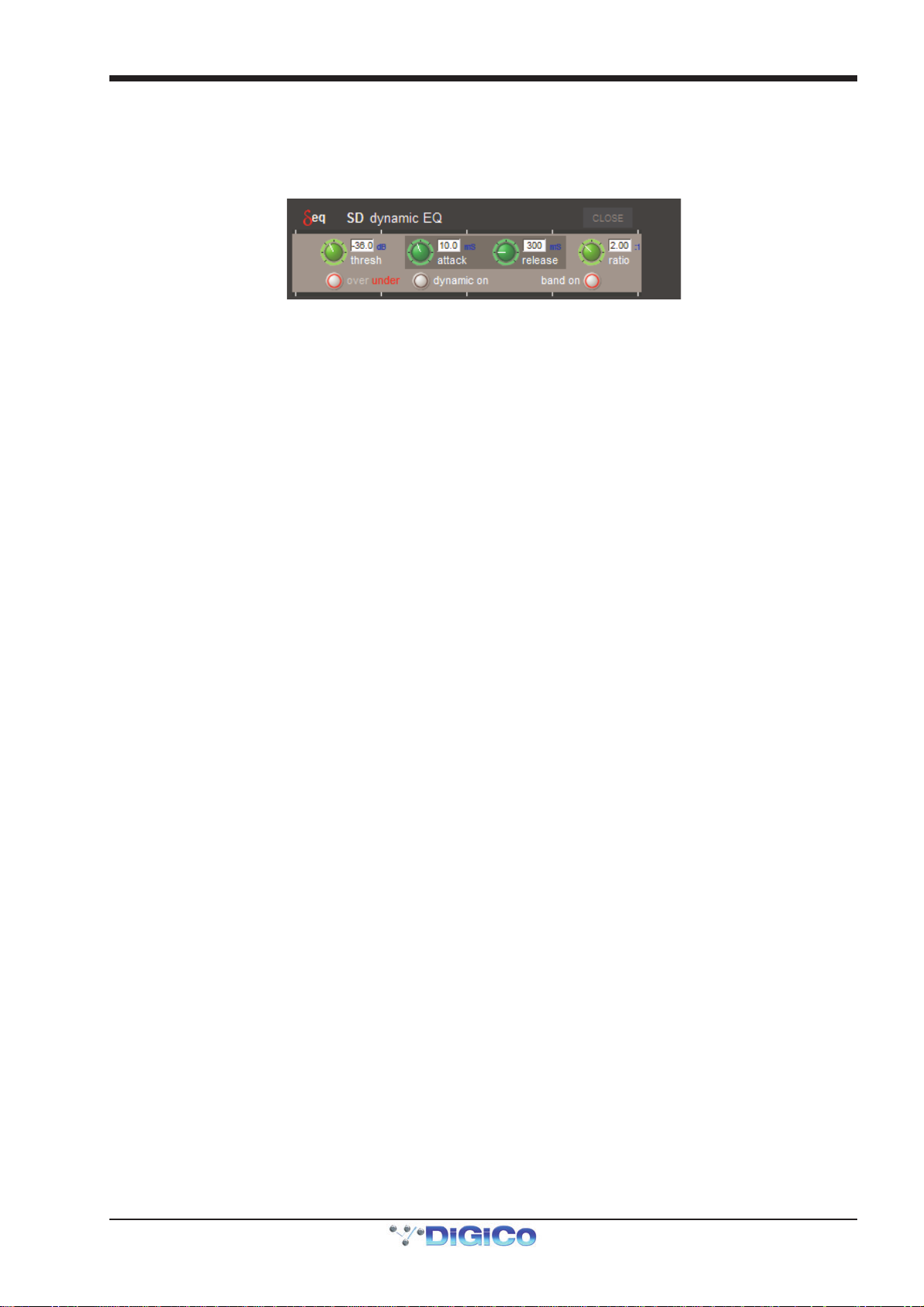
Dynamic EQ
In a dynamic EQ module, the EQ adjustment is applied dynamically, based on the level of the incoming frequency relative to a predetermined threshold. Dynamic EQ is accessed by touching the red "Delta" symbol on any EQ band. Activate the dynamic function by pressing the dynamic on button (a red ring will appear in the button). When dynamic EQ is active, you can also mute and unmute the entire EQ band by pressing the band on button (a red ring indicates that the band is unmuted).
When any dynamic EQ bands are on, a dynamic EQ icon appears above the EQ graph in the channel strip (as shown on the
previous page). The four boxes beneath the icon indicate the status of each band – each box is empty (light grey) when the band
dynamics are off, dark grey when the dynamics are on but the band is off, and coloured when the dynamics and band are on.
DiGiCo dynamic EQ can operate in two modes: 'over' or 'under':
Over Mode
To place the dynamic module into Over mode, ensure that the Over indication below the threshold control is not illuminated.
When the signal entering the module passes the threshold, the EQ adjustment (as determined by the frequency and Q controls)
starts to be applied, up to a maximum adjustment, determined by the EQ band gain control. The manner in which the EQ adjustment
is applied once the threshold has been reached is determined by the attack, release and ratio controls.
Gain : Sets the maximum EQ adjustment that could be applied
Frequency / Q / Curve : Adjusts the EQ characteristics
Threshold : Sets the threshold at which the EQ starts to be applied
Attack : controls how quickly the dynamic module responds to level passing the threshold
Release : adjusts how quickly the module responds to a fall in level
Ratio : controls how quickly the maximum adjustment is reached once the threshold level is passed.
Over Mode is generally used with a reduction in gain at a specific frequency, such that when the threshold is reached, a gradual
reduction of level at that frequency is applied. This could be used to control a change in tonal characteristics as a singer pushes
their voice to sing louder.
Under Mode
To place the dynamic module into Under mode, ensure that the Over indication below the threshold control is illuminated.
In under mode, the maximum EQ adjustment (as determined by the frequency, Q and band gain controls) is applied when the signal
entering the module is below the threshold. As the signal level approaches the threshold, the EQ adjustment is reduced to the point
where there is no EQ being applied at the threshold. The manner in which the EQ adjustment is reduced as the signal level
approaches the threshold is determined by the attack, release and ratio controls.
1-19
Page 27
Chapter 1 - Channel Types
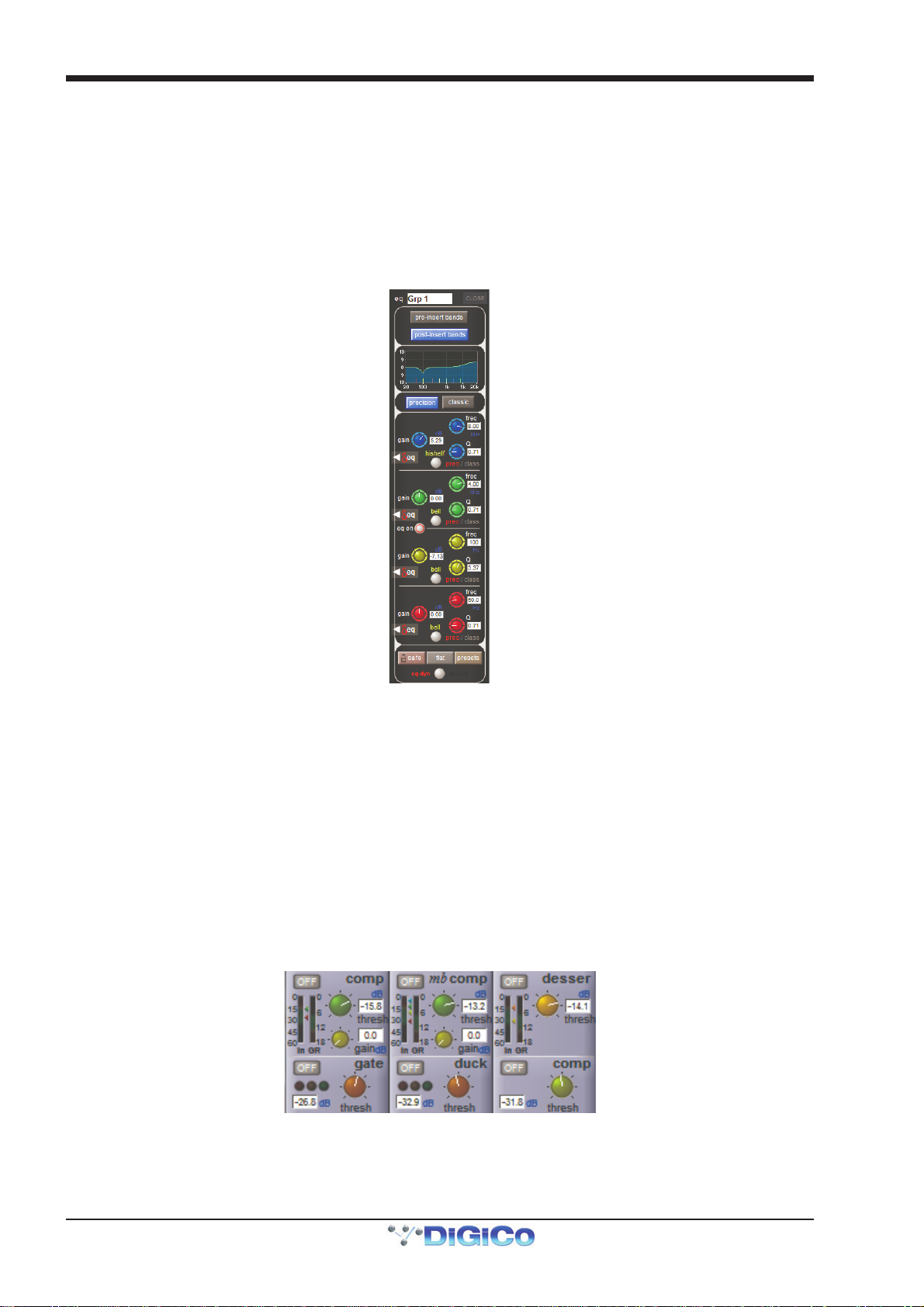
1.6.3 Output Channel EQ ...............................................................
The EQ located in each output Channel is similar in operation to the input channel EQ, with the following exceptions:
Output channel EQs have either have 4 Bands of EQ and HPF/LPF (SD8,9,11) or eight bands – four pre-insert and four postinsert (SD5,7,10). Buttons in the channel strip (pre-insert eq and post-insert eq) and in the EQ display (pre-insert bands and post-insert bands) select which set of bands is assigned to the worksurface and display controls. All eight bands are shown in the EQ graph, with the pre-insert bands shown in lighter shades than the post-insert bands.
The precision and classic buttons above the EQ bands only affect the four bands currently displayed, and not the full 8 bands
available. The pre-insert bands do not have dynamic EQ or bell-shelf switching – the bell button is only used for switching
between precision and classic Q shapes. (SD5,7,10)
1.6.4 Channel Dynamics................................................................
The SD channel dynamics includes two dynamics modules. Module 1 is a fully configurable compressor which can be split into
three frequency bands or configured as a de-esser; Module 2 can function as a gate, a ducker, or a compressor, all with highand low-pass filtering on the key input.
The in-channel display is located below the eq display, with Module 2's controls shown below Module 1's. Each module can be
switched on by pressing the on/off switch in the upper left corner of its channel area. These buttons are grey when off and red
when on.
The display includes an input (In) meter and a gain reduction (GR) meter. The input meter has arrows to its right which display the
current threshold values for each module. Each arrow is distinguished by its colour, which matches its associated threshold pot.
When Module 1 is in Compressor or Multiband mode, threshold and gain pots, each with a value display in dB, are also shown in
the channel strip (when in Multiband mode, the threshold pot affects all bands and the mid band's value is displayed). The Deesser only displays a threshold pot and its value. There is a threshold pot (with value display) shown for Module 2, with three
status indication lights shown when in Gate or Ducker mode.
1: Compressor
2: Gate
Pressing anywhere in either module area brings up the expanded dynamics display.
1: Multiband
2: Ducker
1: De-ess er
2: Compressor
To switch each module between its three modes, touch the button on the left of its expanded display, marked comp/multi/
desser for Module 1, and gate/duck/comp for Module 2. Both modules can be switched on using the on button below their
1-20
Page 28
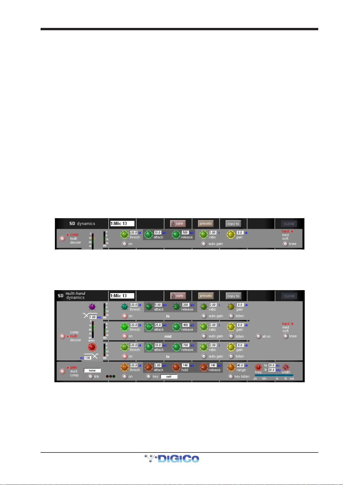
Chapter 1 - Channel Types
threshold buttons. The joint input meter is shown in the expanded display, with the same threshold indication. In multiband
channels, each component has its own meter.
The pots within the expanded display are automatically assigned to the worksurface encoders below the screen when the
dynamics panel is expanded, as indicated by the matching coloured rings around the pots and encoders. When in Multiband mode,
each band is assigned to a row of encoders. When Module 2 is also on, it appears in the bottom row of encoders.
Note that if the gate occupies the bottom row of encoders while the multiband compressor is on, the HF
compressor band is not displayed, and the MF and LF bands both shift up a row.
At the top of the expanded display are buttons marked safe, presets and copy to. Touching safe adds the dynamics to that
channel’s list of channel safes. Touching preset brings up the Presets display which can be used to save and recall presets.
Touching copy to will open the copy to panel with the dynamics section pre selected.
If a link button is shown below the input meter, it allows two channels to be linked together. In other words, the other channel's signal is added to this compressor’s control circuit input, and this channel’s signal is added to the other channel’s control input.
On stereo input channels, the link is always active and the button isn't shown. On stereo output channels, the link button is
available and the link is always between left and right components; it is active by default.
On mono or multiband channels, pressing this button brings up a dynamics link display listing Channels, Groups and Auxes
signal groups in the left-hand side. When one of these signal groups is selected, their available signals are listed in the righthand side of the display. Select a signal to link to and close the display.
The link button is ringed red and the linked channel’s number and name is displayed in the box above it to indicate that there is a
link present. To cancel the link, press the button again and deselect the link signal.
Note that when a link channel has no name, the display repeats the channel number.
Beyond the link function, the different modes of each module have completely separate settings: No settings are copied between
them. If you switch from one mode to the other, the settings will be reset to there defaults. The controls specific to each mode of
each module are described below:
Module 1: Compressor
In Module 1's compressor, threshold, attack, release, ratio and gain controls are provided, each of which function in the
normal way. The compressor has an auto gain function which is switched on by pressing the auto gain button below the ratio
pot. This function automatically adjusts the gain makeup when changes are made to the threshold, thus keeping the compressor
output steady. The threshold knee can be switched between hard, mid and soft using the knee button in the right side of the
module. The gain reduction (GR) meter is duplicated in this display.
Module 1: Multiband Compressor
In Module 1's multiband compressor, each band includes all of the parameters found in the single band compressor. The link function remains available for the whole compressor, and is not assigned to any band. The bands can be switched on individually using the on buttons in the left-hand side of each band, or together using the all on button in the display’s right.
The crossover frequency between bands is controlled using the purple and red pots to the left of the hi and lo bands. Each
crossover has a range of 20Hz to 20kHz, and the crossover frequencies are displayed below each pot. Each band can be
auditioned by pressing the listen button below each gain pot.
Important Note: In software versions earlier than V463, when any band is switched off, that band will not pass
audio. In later software versions, bands which are off are bypassed rather than muted.
1-21
Page 29
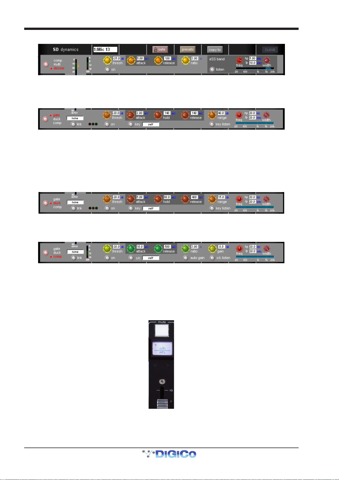
Chapter 1 - Channel Types
Module 1: De-esser
The de-esser's controls are similar to those of the compressor, with the following exceptions: In the right side of the module, there
is a band-pass filter control for the de-esser sidechain, with pots provided for the centre frequency and filter width. The -3dB
points for the hi-pass (hp) and lo-pass (lp) frequencies are shown. The filtered sidechain can be auditioned by pressing the
listen button. Note that there is no makeup gain included.
Module 2: Gate
Gates can be keyed by a different signal by pressing the key button below the attack pot. This brings up a Gate Key Route display from which a key input can be selected. Consecutive channel gates can be keyed by consecutive input signals using the ripple channels function. The key button is ringed red and displays the key input in the text box to its right to indicate that another signal is keying the gate. The key input signal can be auditioned by pressing the key listen button underneath the range pot.
There is a band-pass filter available: the width control adjusts the width of the band being passed, and the freq control moves
that band through the frequency range. The hi- and lo-pass sidechain filter frequencies are displayed.
To the right of the link button, there are red, amber and green status indication 'traffic lights'.
Module 2: Ducker
The ducker has exactly the same controls as the gate, though the sidechain performs the opposite function of ducking the signal
rather than gating it.
Module 2: Compressor
Module 2's compressor is identical to the single band mode of Module 1, with the addition of the band-pass filter described above,
and a sidechain input function (S/C) which functions exactly like the key function of the gate.
1.7 LCD Functions
1.7.1 Introduction to LCD Functions .............................................
The LCD button/display is located above the channel fader, and is included in every channel in both the centre section and side
sections of the consoles. The channel number is displayed in the top half and the current function mode of the button is displayed
in the bottom half of the display and is also indicated by its colour.
LCD buttons (SD5,7) or Select Buttons (SD8,9,10,11) are able to fulfil a number of different functions, and are even involved in
selecting their own function. These functions are accessed by pressing the lcd function button, located above the bank buttons
on each section of the desk. When this button is pressed, LCD displays for the channels associated with it turn yellow, indicating
that they have become function mode selectors:
1-22
Page 30
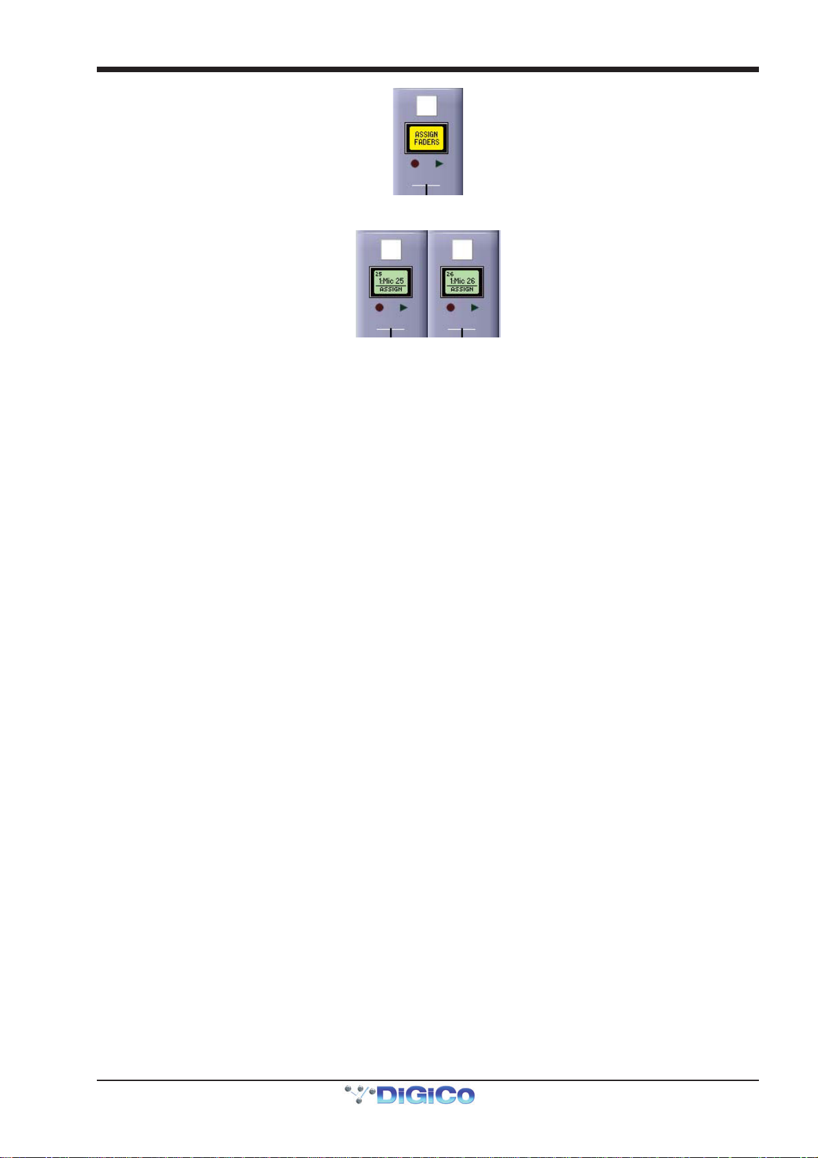
Chapter 1 - Channel Types
Selecting one of these options assigns that function mode to the LCD/select buttons for all the channels within the banks
associated with that lcd function button.
There are twelve different function mode options.
1.7.2 Solo........................................................................................
When an lcd function button is pressed, the left-hand LCD display is labelled SOLO. When SOLO mode is selected, the LCD/
select buttons become solo buttons. The bottom half of the LCD display indicates which solo busses are available to the channel,
as defined in the channel Setup display and the SOLO CHOICE function mode (described below). The display also shows
whether each buss is AFL or PFL, as defined in the top-left corner of the master solo display.
In SOLO mode, the LCD displays are coloured according to their channel type when not soloed, and coloured green when soloed.
Note that this is the default mode of the LCD/select buttons, current when no other function modes have been
selected.
1.7.3 Solo Choice...........................................................................
When an lcd function button is pressed, the second LCD display from the left is labelled SOLO CHOICE. When this mode is
selected, the LCD/select buttons are used to select the solo bus assignment for that channel, toggling between 1, 2 and 1+2.
In SOLO CHOICE mode, the LCD displays are coloured cyan.
1.7.4 GANG .....................................................................................
When an lcd function button is pressed, the third LCD display from the left is labelled GANG. When this mode is selected, the
LCD/select buttons are used for linking together all channel controls. All LCD/select buttons which are then pressed will have their
controls linked. In the case of currently ganged channels, the LCD/select button can be used to remove them from their ganging
group. The colour of the GANG symbols in the bottom left-hand corner of the on-screen channel display indicate what ganging
groups exist: All faders which are ganged together will share one colour. Each time the GANG lcd function is selected, a new
ganging group is started, as indicated by the GANG symbols turning a different colour.
To gang channels across different surfaces of the console, activate the GANG LCD function on each surface before starting to
build the gang. A single cross-surface gang can then be created using the LCD/select buttons in the usual way.
To stop adding channels to the current gang and start a new gang, simply reselect the GANG LCD function.
When channels are ganged together, operating any of their channel controls will cause all other channels within the ganging
group to replicate that movement. Pan and phase controls are not included in gangs.
Note that it is the level change associated with the fader movement which is replicated, not the physical
distance the fader is moved.
Note also that when a ganged channel is muted, those channels within the ganging group which were
already muted will stay muted. When the channel is then unmuted, all channels unmute, irrespective of
whether they had been initially muted.
Note also that when any member of a gang is Assigned, the Undo function will always take the faders back to
their position when the channel Assignment was made.
Channels can be temporarily isolated from Gangs by pressing the Option button.
Note that gangs cannot be edited once they have been created.
1-23
Page 31

Chapter 1 - Channel Types
L
1.7.5 JOIN CG .................................................................................
When an lcd function button is pressed, the fourth LCD display from the left is labelled JOIN CG. When this mode is selected, the LCD/select buttons can be used for assigning channels to Control Groups. Control Groups enable a number of channel output levels and mute functions to be controlled from one master fader. Control Groups can include any combination of channels from all four channel types. For more detailed information on Control Groups, please refer to the Master Section of this Manual.
1.7.6 Assign Faders........................................................................
To assign channels to the worksurface, enter ASSIGNFADERS mode. The LCD displays will turn dark green and their lower
halves will read ASSIGN. Press the LCD/select buttons for each of the channel strips to which you wish to assign new channels.
Press LCD Functi o n bu tt o n
then Ass i gn Faders
Press LCD button(s)
for Assi gn ment
ayout/Channel Faders
Click down arrow
Touch first channel
To select the channels you wish to assign to those channel strips, open up the Channel List display, accessed by going to the
master screen and touching Layout > Channel List. There you will find a list of all input, output and control channels that are
present in the session structure, grouped by channel type. Open up the channel list for the channel type of the first channel to be
assigned by touching the appropriate down arrow in the left-hand column. The channel list can be scrolled using the scroll bar on
the right of the display:
To assign one of the listed channels to the channel strip, simply touch the channel name in the list. The remaining channels can
now be assigned in the same way, The channels selected in the Channel List display are assigned to the selected channel
strips in ascending order, starting with the lowest channel in the bank.
Note that the assign function is restricted to the currently selected bank.
Note also that when new channels are added to a session, or when a session is created, all of the existing
channels can be assigned to the worksurface using the rebuild banks function within the Session Structure
display.
Open
to expa nd li st
to assign
1.7.7 Unassign Faders ...................................................................
To remove channel assignments from a channel strip, enter UNASSIGNFADERS mode. The LCD displays will turn dark green and
their lower halves will read UNASSIGN. Press the LCD/select button for any channel strip you wish to clear, and the strip will go
blank.
1.7.8 Swap Faders (SD5/SD7) .......................................................
To swap the positions of two channels, enter SWAP FADERS mode. The LCD buttons will turn dark green and their lower halves
will read SWAP. Press the LCD button for the two channels you wish to swap, and they will swap places.
1-24
Page 32

Chapter 1 - Channel Types
1.7.9 Move Faders (SD5/SD7) ........................................................
To move channels within a channel strip, enter MOVEFADERS mode. The LCD buttons will turn dark green and their lower halves
will read MOVE>>. Pressing any LCD button will result in that channel moving one space to the right. If the bank is full all channels
to the right of the moved channel will move right, and any channel which had been occupying channel-strip 12 will be lost from the
layout. If there is a blank channel strip anywhere to the right of the moved channel, any channels further right than the blank will
not move, and the moved channels will simply fill the blank space.
For example, if the bank is occupied by input channels 1 to 12, pressing MOVE>> on channel 6 will result in channels 6 to 11
moving one space to the right, leaving a space in channel strip 6, and channel 12 being removed from the layout. Pressing
MOVE>> on channel 4 will then result in channels 4 and 5 moving one space to the right, filling the space that was in channel strip
6 and leaving a space in channel strip 4.
When blank channels are moved they simply swap positions with the channel to their right. Note that any blank channels immediately to the right of the one being moved will move as well, and the blanks will move by as many channel strips as there are blank
spaces being moved.
For example, if channel strips 1 to 3 are blank and Input channels 1 to 9 are occupying strips 4 to 12, pressing MOVE>> on
channel strip 2 will result in blanks 2 and 3 swapping places with Input channels 1 and 2.
1.7.10 Copy Bank From .................................................................
To copy a different bank of channels to the current bank location, press COPYBNKFROM. The message ‘PRESS | A BANK |
BUTTON | FOR | COPYIN | FROM’ will be shown across the LCD displays. Simply press the bank button for the bank which you
want to copy to the current location.
1.7.11 Copy Bank To ......................................................................
To copy the current bank to different bank location, press COPYBNKTO. The message ‘PRESS | A BANK | BUTTON | FOR |
COPYIN | TO’ will be shown across the LCD displays. Simply press the bank button for the bank to which you want to copy.
1.7.12 Clear Bank...........................................................................
To clear all channels from a bank, press CLEARBANK. ‘The message ‘CONFIR| CLEAR| BANK:| YES| NO’ will be shown across the LCD displays. Press NO to cancel the action or YES to continue.
Note - Banks can be moved between layers, and also between sections of the console.
Note also that the Fader Banks display on the master screen can also be used for altering the bank layout.
Note also that there is no undo function for these actions. Proceed with care!
1.7.13 Create Multi.........................................................................
The final LCD function, CREATE MULTI, is used to place new Multi channels onto the surface. When active, the LCD function buttons of any assigned faders will remain in their SOLO mode, whereas all unassigned faders will be available for creating new Multis. Once created, Multis can be configured in the normal way, as described below.
1.8 Multi Channels
If you are working in Surround, or using another multi-channel format, you can create LCR, LCRS and 5.1 busses in the Session
Structure window described in Section 1.5.1.
Multi-channel inputs are controlled by routing each component through a mono channel and then linking those channels via a 'Multi'
channel. To start with, use the normal input and output routing procedures to route each component through a channel. There are
then two options for creating a Multi channel: If you want to create the Multi in place of the channel strip for its first component,
open the Setup display for the first component and select Multi at the top. Alternatively, if you want to create a Multi in a
previously unassigned location, use the CREATE MULTI LCD function described above.
Whichever procedure you use to create the Multi and assign it to a fader, you will now be presented with a Setup Multi Chan- nels display. Select the format – LCR, LCRS, 5.1 or multi-input (which allows you up to 11 components) – and then press the LCD buttons for the remaining component channels, working down the displayed list in order. Channel names will appear against each component. Channels can then be left on the worksurface or removed using the buttons towards the base of the display. Finally, touch OK to close the display to link the channels together.
Create M ulti and
assign fader
Select multichannel format
Select channels,
leave/remove,
press OK
1-25
Page 33
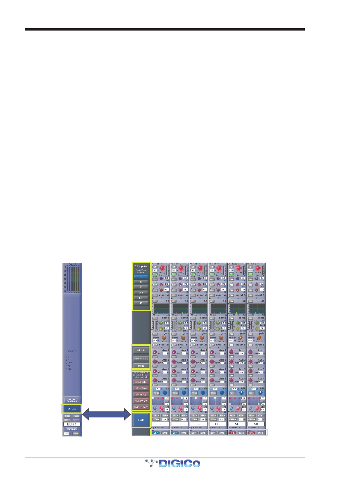
Chapter 1 - Channel Types
Multis can be unfolded in order to access controls for each component. This is done by pressing the Unfold button in the channel
strip. When unfolded, the normal channel assignments are hidden, each component is given its own channel strip, and a Multi
master channel is displayed to their left (shown over the page).
Note that if leave (channels on the surface) was selected when the Multi was created, the component channel
strips are available whether or not the Multi is folded.
In the top section of the unfolded Master channel, buttons for each component channel allow you to define which channel's elements are displayed in the Folded View, if any Folded Controls are activated (see below).
In the middle area of the unfolded Master channel, the links between component channels can be edited. Links function in the
same way as Gangs, but are limited to the components of a multi-channel signal. To create or edit links, press the Set Links
button so that it goes red, then press the LINK buttons below the channel names in the channels to be linked - each button will
take on the same colour, indicating that they are linked. To remove a link, press the LINK button while Set Links is active. Note
that if you start a set of links and then de-link and re-link another channel, a new link set will be started, as indicated by the
introduction of a new link colour. When you have finished linking channels, deselect Set Links. You can also clear all links and
link all using the buttons below Set Links.
Below the link buttons in the unfolded Multi Master, there are buttons for each element in the components' channels - trim &
delay, filters & eq, dynamics and faders & mutes. Pressing one of these buttons will cause that element in all the channels
to match those of the Folded channel.
Once you have finished with the unfolded view, press the FOLD button to fold the channels back together.
In folded view, the channels included in the Multi are shown in the middle of the Multi channel strip. Touching the Folded Control
button brings up four buttons which allow you to define which channel elements are displayed in the folded channel strip: Input,
EQ, Dynamics and Aux Sends . These settings reflect the channel which has been set as the Folded View channel; the Folded
View Channel is shown with a blue (as opposed to black) channel number in the list displayed in the folded channel, if any Folded
Controls are activated. Adjusting any element in the Folded channel strip will affect all linked channels.
Note, however, that if channels have different settings when linked, changes in hidden, linked channels will
be made relative to the change in the Folded View channel, but the display will only reflect the Folded View
channel.
Note also that activating the Aux Sends Folded Controls will result in the channel components list becoming
hidden.
Folded
Folded
channel
view
Edit Links
Unfolded
1-26
Match
Settings
Link Indicators
Page 34

Chapter 1 - Channel Types
The fader and mute on the Multi channel strip will always affect all of the Multi members irrespective of the link settings and thus
serves as a “Master” fader and mute for that multi’s members.
The on screen indicators for Channel Mute, Hard Mute and CG Mute at the bottom of the Multi strip give an indication as to
whether any of the Multi members are Channel Muted, Hard Muted or CG Muted. If any member has any one of these types of
mute active, the Folded Multi’s indicator will show this.
In the Folded Multi view the worksurface Mute switch can have one of three different states:
1) Not lit (OFF) - the Multi Master Mute is not active - unmuted. Note that if any channels are muted individually, the mute indicator
below the unfold button will be red.
2) Lit and red (ON) - the Multi Master Mute is active - muted.
3) Flashing from OFF to ON - the Multi Master Mute is active but at least one of the members has been unmuted (opened) thus
overriding the Multi Master Mute on one or more of the Multi’s Members.
Edit Multi
At the bottom of the Multi strip there is also an Edit Multi button which allows the members of the Multi to be changed or the Multi
to be cleared or deleted. Pressing this button will open the Setup Multi Channels panel.
To edit the members of the Multi, press one of the grey buttons on the left to select a member and then press one of the
worksurface Channel Select buttons to assign a channel. To clear the Multi, press the Clear All button at the top of the panel and
then either select a new type of Multi or delete the Multi completely by pressing the Delete Multi button at the bottom of the panel.
1-27
Page 35

Chapter 2 - The Master Screen
SD Series Software Reference
Chapter 2:
The Master Screen
2-1
Page 36
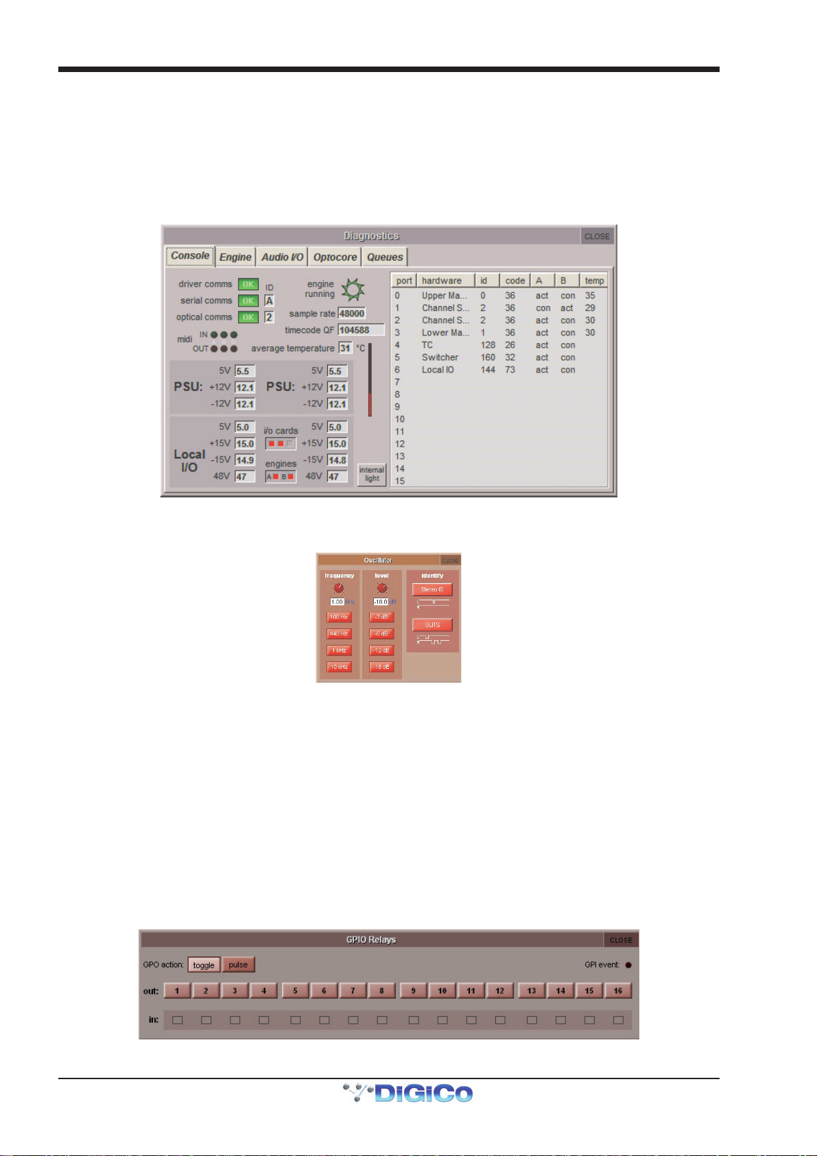
Chapter 2 - The Master Screen
This chapter describes all of the functions accessed from the Master Screen. The chapter focuses on the functions of the menu
buttons across the top of the Master Panel, working through the buttons from left to right. Master Section worksurface elements
are described within the context of the Master Panel display.
To open the Master screen press the worksurface Master button in the centre section (SD8, SD10, SD9, SD11).
2.1 System Menu
2.1.1 Diagnostics ............................................................................
The Diagnostics display is explained in the Troubleshooting chapter.
2.1.2 Oscillator ...............................................................................
The oscillator is configured in the Oscillator display.
The frequency of the oscillator is controlled by the left-hand frequency pot, and its audio level is controlled by the right-hand
level pot. The buttons below each pot, can be used to set the oscillator to standard frequencies (100Hz, 440Hz, 1kHz, 10kHz)
and levels (-3dB, -6dB, -12dB, -18dB). The current value of each parameter is displayed below its pot.
For Stereo channels, the 1 KHz oscillator can be set to produce a pulsing ID signal on the left signal or a GLITS signal as indicated
by the on-screen graphic.
2.1.3 GPIO Relays ..........................................................................
Selecting GPIO Relays opens a panel displaying the current GPI and GPO states. The panel will show the GPIO configuration for your console. The numbered 'out:' buttons allow GPOs to be triggered. If the toggle button above them is active (lighter), then touching a GPO button will switch it on (red) or off (brown). If the pulse button is active, touching a GPO button will send an 'on' pulse.
Note that GPOs which are on when entering pulse mode will stay on. Touching them while in pulse mode will
switch them off.
The GPI event light in the top right-hand corner indicates when GPI messages arrive. Below the GPO buttons is a row of
indicators (labelled 'in:') showing the current state of each GPI.
2-2
Page 37
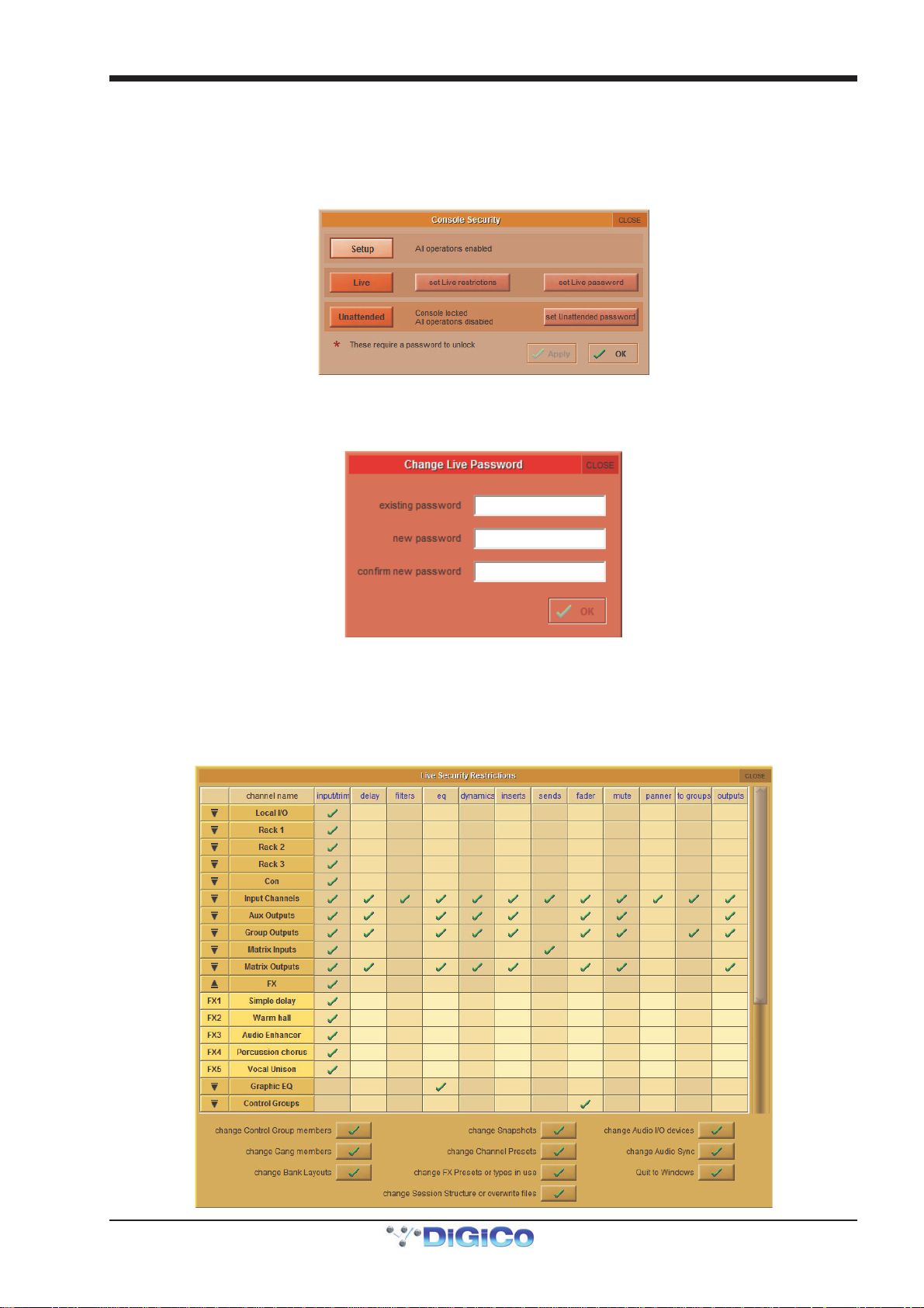
Chapter 2 - The Master Screen
2.1.4 Security .................................................................................
Security modes are selected in the system menu, with a choice of three levels of access:
Setup: Users have full access to every function on the console.
Live: Access to elements of the console can be limited, and password protected.
Unattended: The console is locked, and cannot be operated.
User passwords can be defined for the Live and Unattended modes. To set a password, press the Set Password button. Enter
the old password then the new one twice, and press OK. By default, the passwords are blank.
NOTE: If you should forget your password, call your Distributor to obtain a reset password. Entering the master
override password will allow new passwords to be set.
To modify restrictions in Live mode, press the Set Live Restrictions button in the Console Security Panel. A range of parameters are shown, with a tick indicating that access is allowed and a cross that the item will be locked out in Live mode. Each group list can be expanded for item-specific restrictions by pressing on the down arrow in the left-hand column, as shown for FX below:
2-3
Page 38
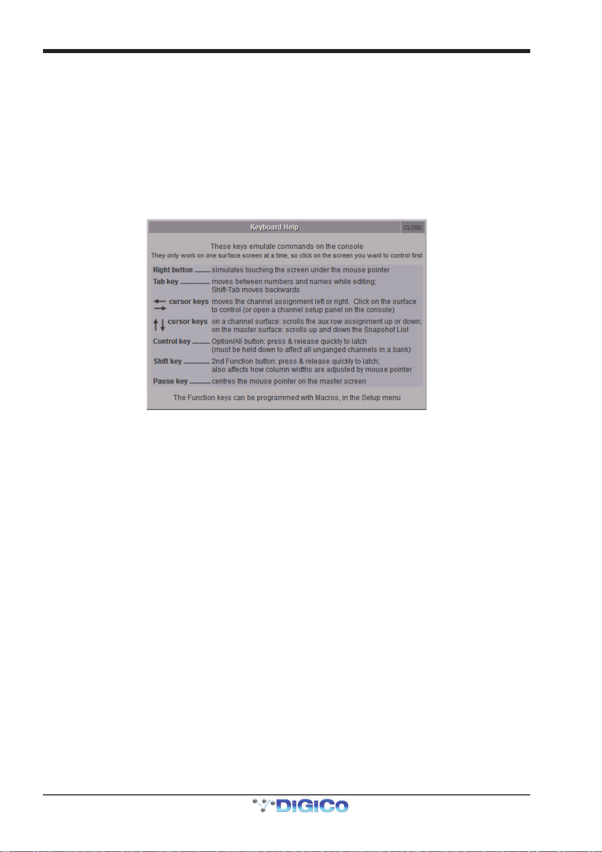
Chapter 2 - The Master Screen
2.1.5 Signal Over Indicators..........................................................
Pressing this entry in the System menu opens the Signal Overs panel, showing details of any signals which have peaked. Touching an entry in the Signal Overs list brings the channel to the surface to be adjusted. The Signal Overs panel also duplicates the Clear Over Indicators button.
Note that the Signal Overs panel can also be set to open automatically when a signal peaks. This is done in
the Status tab in the Options menu.
2.1.6 Overview Clear Screen ........................................................
Some panels such as the information bar and the status indicators can be dragged with the trackball to external overview screen. To quickly reset the position of these panels back to the Master screen, press the Overview Clear Screen button, and select
Yes in the confirmation pop-up which appears.
2.1.7 Keyboard Help ......................................................................
The Keyboard Help button opens up a display detailing the console control elements which are available via an external keyboard:
2.1.8 F10: Reset FX ........................................................................
Pressing this entry in the System sub-menu will reset the FX module audio. This allows, for example, lengthy delay and reverb
tails to be killed. To complete the reset, select Yes in the warning pop-up which appears.
Note that this will briefly bypass all of the FX units.
2.1.9 F11: Reset Engine .................................................................
Pressing this entry in the System sub-menu will restart the audio engine
Note that this will briefly interrupt the audio - do not use this function unless absolutely necessary.
2.1.10 F12: Reset Surfaces ............................................................
Pressing this entry in the System sub-menu will reset all of the worksurface controls. This function will briefly interrupt the audio
on the Local I/O only.
2.1.11 Set Date & Time..................................................................
Pressing this entry in the System sub-menu will open the Date and Time window for the console's operating system.
2.1.12 Quit to Windows (SD5, SD7)...............................................
Pressing this entry in the System sub-menu quits the SD console software but leaves windows running. If the session is not saved, pressing Quit to Windows will bring up a warning display. Press Yes to quit without saving, or No to cancel the quit.
2.1.13 Restart (SD5, SD7) ...............................................................
Pressing this entry in the System sub-menu shuts the console’s control computer down and restarts it. If the session is not saved, pressing Restart will bring up a warning display. Press Yes to restart without saving, or No to cancel the restart.
2.1.14 Shutdown ............................................................................
Pressing this entry in the System sub-menu shuts the console’s control computer down. If the session is not saved, pressing Shutdown will bring up a warning display. Press Yes to shut down without saving, or No to cancel the shut down.
2.1.15 Shutdown All.......................................................................
When consoles, engines or remotes are mirrored together in Full Mirror or expander mode, an additional Shutdown All button will appear at the bottom of the system menu. When pressed, it will shut down all SD consoles or remotes which are in either Full Mirror or Expander mirroring modes.
2-4
Page 39

Chapter 2 - The Master Screen
2.2 Files Menu
2.2.1 Templates..............................................................................
Touching on Templates in the Files menu brings up the Session Templates display. This lists any ordinary session files which are located in the folder d:\Templates (or c:\Templates if not on a console), along with key session information.
Note: If this folder doesn't exist, it should be created manually. The required template sessions can then be
copied into it.
To load a Session Template, simply select it in the list and touch the Load button.
2.2.2 Session Structure..................................................................
Touching on Session Structure in the Files menu brings up the Session Structure display. This is where a session is named and where the channel allocation and sample rate for the session are configured. While changes to session structure can be made once a session has been started, it is best to try and set these parameters before configuring the session. Session Structure changes are not implemented until the Restructure button in the bottom right-hand corner of the display is pressed.
To name the session, touch the session title box, type the session name using the either the on-screen or external keyboard, and press OK.
Set the Session sample rate at the top of the panel.
It is worth remembering that each output (buss) allocated also uses up one of your processing channels.
Below the session title, each channel type has its own setup row, which includes clear all and auto-route buttons, and a display of the current number of channels in the session. To adjust any of the channel allocations, touch on the associated channel count box, and either enter a number using the pop-up number keypad, or adjust using the assigned touchturn controller.
The SD7 is the only SD Series console where all these parameters are adjustable. For example, on an SD8, SD9 and SD11, only
the Aux buss and Group buss allocations are adjustable and all other Parameters are fixed.
For specific console model information, please refer to Configuring Session page in the Getting Started Section.
Note also that processing channels are reserved for the master buss, talkback channel and stereo solos.
2-5
Page 40
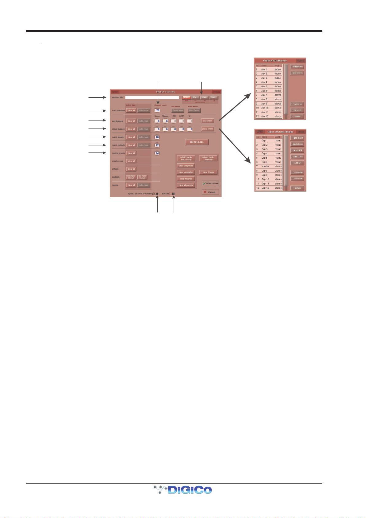
Chapter 2 - The Master Screen
busses
Tou ch number’s to
keypad or touchturn
S
Set Order of Aux and
Select session
Group busses
Enter Se ssion ti tle
Set number of Input Channels
Set number and type of Aux
et number and type of Group
Set number of Mat rix I nput s
Set number of Mat rix Outputs
Set number of Control Groups
edit wi th pop- up
Total number
of unallocated
processing
Total number
of spare
sample rate
Note - The Above picture shows the SD7 Session Structure Panel. Pressing the Default All button followed by
the Restructure button will automatically configure a new session with the following setup where the inputs
from Port 1 are routed to input channels and the Master Buss is routed to Local outputs 1 & 2 and also to
Port 1 rack outputs 1 & 2. All input channels will be routed to the Master Buss and the console headphones
will be fed by the Master Buss when nothing else is soloed.
If the clear all button is pressed, any non-default routing or processing (EQ, dynamics etc) will be cleared from the channels in
the session when the Restructure button is pressed. This is especially useful when restructuring an existing session to make a
new session.
The auto-route button automatically routes the physical inputs and outputs in the rack to the inputs and output channels in the
session when the Restructure button is pressed, thus saving the operator from manually routing them in the channel Setup and
Output displays. For example, auto-routing 48 inputs will route the first physical input (eg 1:Mic 1) to input channel 1, the second
physical input (1:Mic 2) to input channel 2 until you either run out of inputs or channels. Auto-routes are as follows:
- Input Channels auto-route with physical inputs
- Aux, Group and Matrix Channels auto-route to physical outputs
- Matrix Inputs auto-route with group outputs
Note that auto-routing can only be used in conjunction with the Clear All button, and is not available for
input channel direct outs.
Important Note: auto-routing overwrites any previous input and output routing.
Note also that the outputs of Aux, Group and Matrix channels are auto-routed in sequence: Aux outputs
followed by Group outputs, followed by Matrix outputs.
The send point for input channel direct outs can be set globally using the direct sends button toward the top right-hand corner
of the display. The button is made active by touching the input channels Clear All button. The direct sends button then toggles
between Post-Fader, Pre-Fader and Pre-Mute.
Similarly, the send point for aux channel outputs can be set globally using the aux sends button to the left of the direct sends
button. The button is made active by touching the aux busses Clear All button. The aux sends button then toggles between
Post-Fader, Pre-Fader and Pre-Mute.
2-6
Page 41

Chapter 2 - The Master Screen
Aux and Group Order
By default, the aux and group channels are ordered with the stereo channels following the mono channels. These orders can be altered in the Order of Aux Busses and Order of Group Busses displays, accessed by pressing the Aux Order and Group Order buttons on the right hand side of the display.
Busses can be added using the buttons in the top-right of the display. To change a busses position or delete it, touch the buss in
the display’s list and use the buttons in the bottom-right of the display.
Note that only the mono/stereo format of the Busses and their display within the input channel can be
reordered in this display. Channel settings are not reordered. The console layout can be reordered using the
Rebuild Banks function described below.
The Master buss is the first stereo buss, regardless of the order you place the busses in.
The audio i/o and comms rows beneath the standard channel-type rows allow the settings of the audio io cards and talkback
function to be reset.
The clear snapshots and clear macros buttons towards the bottom-right of the window can be used to clear any existing snapshots and macros when making a new session.
Note that the clear automation function has not yet been implemented.
Rebuild Banks : When changing the number of allocated channels in any section (input channels, busses etc), you can restructure the session without rebuilding banks, meaning that any additional channels you have allocated will not be “placed” on the worksurface, and need to be manually assigned to faders. If however, you restructure a session with Rebuild Banks (either Horizontally or Vertically) enabled, the worksurface will be built with all channels available on the worksurface in a default layout. Rebuilding horizontally will result in input channels being spread across the top layer of both sides of the console, using as many banks as required, with output channels being assigned to Layer 2. Rebuilding vertically will result in input channels being assigned to Layer 1 on the left side of the console, and output channels to Layer 1 on the right. See the Session Structure section of Chapter 3 for more details.
Note that when Rebuild Banks is used, any non-default configuration of the channel layout is lost.
To implement changes in the Session Structure display touch the Restructure button in the bottom right-hand corner. To exit
the display without implementing the changes, touch Cancel, located below the Restructure button.
To clear unimplemented changes from the display, touch REVERT, located in the top left-hand corner of the display.
2.2.3 Load Session.........................................................................
Touching this entry in the File menu opens the Load Session display. The left-hand column of the display shows the file directory. At the top of the directory are two buttons which switch the list of folders below them between the contents of the console computer’s internal d:\Projects folder and the contents of a removable USB drive. Each folder can be expanded by clicking the + symbol to its right. The list can be scrolled using the scroll bar to its right.
When a folder or sub-folder in the left-hand directory is expanded, a list of the session files contained within it appears in the list in the centre of the screen. The list displays the Filename, creation Date & Time, and Description of the session. In addition, the list also displays the number of Inputs, Auxes (mono, stereo), Groups (mono, stereo) and Matrix channels (ins/outs).
To load a session, touch the session in the list and press Load, located in the bottom right-hand corner of the display. To close the display without loading a session, press Cancel, located below the Load button and also found in the top right-hand corner of the display.
Once a session is loaded, a summary of the currently loaded session is displayed in the Information Bar which is normally
found on the Master screen. Once any changes have been made to the session, the File: indication in this display will only show
the folder of the most recently saved session, not the file name.
Note also that if any of the buttons in the right-hand column of the window are active, sessions cannot be
selected for loading from the list.
2-7
Page 42

Chapter 2 - The Master Screen
Select a File
I
d
File Details
Select Internal or
Removable USB
nternal files saved
in D:\Projects
Press Loa
Note that column widths can be adjusted by dragging their borders within the title row. To return all columns to their default widths, press RESET WIDTHS, in the top left-hand corner of the window.
Partial Load
When a session file is selected from the list, the Partial Load button becomes available in the top right corner of the panel.
Pressing this button opens the panel shown below where elements of the session can be selected for Partial Loading.
Possible selections include ranges of Input channels, Matrix inputs, Matrix outputs and Graphic EQs, banks and layout, Presets
and Macros.
There are also options to Partial Load all or some of the Snapshots from the selected session.
Replace Snapshots will remove the existing Snapshot list and replace it with the partially loaded one. Add Snapshots will open a Snapshot list where snapshots can be selected to be imported into the existing session.
Note that if Snapshots are imported that contain data that the existing session is not capable of recalling (eg
channels that don't exist) then this data will be ignored when the Snapshot is recalled.
The numbering of imported Snapshots will be the same as their original numbers so there may be duplication in Snapshot numbers after the import.
2-8
Page 43

Chapter 2 - The Master Screen
Enter a Filename
Enter a Description
I
To create a new folder
2.2.4 Save Session.........................................................................
Touching this entry in the File menu saves the current session. Once the session has been saved, a confirmation pop-up appears
displaying the location of the saved session file.
Note that this function overwrites the most recently saved session. If you want to retain the most recently saved session, save
the current session as a new session.
2.2.5 Save As New File..................................................................
Touching this entry in the File menu opens the Save Session display. At the top of the display are two text boxes showing a file
name and session title. The file name will normally be ‘sessionxxx.ses’ where xxx is an auto-incrementing number and the
session title is the same as the current session. If the session has not been changed since it was last saved, the file name will
be the same as the current session. To edit the file name and session title, touch the relevant text box, enter the new name or
title in the on-screen or external keyboard, and press OK. To overwrite another session, or to save the session in a new folder
but with a previously used name, touch the session of that name and its name will appear in the file name box.
The location of the session file to be saved is defined in the directory in the left-hand side of the display. At the top of the directory are two buttons which switch the list of folders below them between the contents of the console computer’s internal
d:\Projects folder and the contents of a removable USB drive. Each folder can be expanded by clicking the + symbol to its right.
The list can be scrolled using the scroll bar to its right. Touch the button and folder within which you want to save the session.
To create a new folder, select the location for the folder in the way described above, touch the new folder button in the right-
hand side of the display, type the folder’s name using the external keyboard and press the external keyboard’s return button. To
rename a folder, touch the folder within the directory, touch the rename folder button in the right-hand side of the display, type
the folder’s new name using the external keyboard and press the external keyboard’s return button.
To delete a folder, touch the delete folder button in the right-hand side of the display, touch the folder to be deleted and touch Yes in the confirmation pop-up which appears.
Note that this action cannot be undone.
Once the session has been named and its save location has been selected, save the session by pressing Save, located in the bottom right-hand corner of the display. To close the display without saving, press Cancel, located below the Save button and also found in the top right-hand corner of the display. If you attempt to save the session under a file name which already exists within that folder, a pop-up appears, warning that continuing will cause the file with that name to be overwritten. Touch Yes to continue, No to cancel.
Note that overwriting the most recently saved session can be performed more quickly using the Save Session function described above.
Once the session has been saved, a confirmation pop-up appears displaying the location of the saved session file.
To rename a file, touch the file to be renamed followed by rename file, located in the right-hand side of the display, enter the new name into the on-screen or external keyboard and press OK. If rename file is pressed without a file being selected, the first file in the list will be automatically selected for renaming.
Note that the file name is the only file element that can be edited once the file has been saved.
To delete files, select the folder containing the files to be deleted and touch delete files. To delete all files in the folder, touch select all, followed by confirm delete. To delete one file or a selection of files, touch the files you wish to delete followed by confirm delete. To delete a consecutive range of files, touch select range, touch the first and last files included in the range to
be deleted, and touch confirm delete. To complete the deletion process, touch Yes in the confirmation pop-up which appears.
Select Internal or
Removable USB
nternal files saved
in D:\Projects
in D:\Projects
2-9
Page 44

Chapter 2 - The Master Screen
Note that column widths can be adjusted by dragging their borders within the title row. To return all columns to their default widths, press RESET WIDTHS, in the top left-hand corner of the window.
Set Backup
Located on the right hand side of both the Load Session and Save as new file panels, are the Set backup and Copy backup
Buttons. The backup function enables batch copying of session files to and from a connected removable drive. Press the set
backup button and touch on the session files to copy to/from the removable drive. Once selected, an asterisk will appear in the
"B" column of the panel. Now press the copy backup button and after the confirmation stage, the selected session files will be
copied to/from the removable drive.
Note that the Copy Backup button will not be available until a valid removable drive has been connected to
the console's USB port.
2.2.6 Load Presets .........................................................................
Touching this entry in the File menu opens the Load Presets display. This allows Channel, FX, Graphic EQ and Matrix presets created in other sessions to be imported into the current session. The left-hand column of the display shows the file directory. At the top of the directory are two buttons which switch the list of folders below them between the contents of the console computer’s internal d:\Projects folder and the contents of a removable USB drive. Each folder can be expanded by clicking the + symbol to its right. The list can be scrolled using the scroll bar to its right.
When a folder or sub-folder in the left-hand directory is touched, a list of the Preset files contained within it appears in the list in
the centre of the screen. The list displays the Filename, creation Date & Time, and Description of the preset file. In addition,
the list also displays the number of Input, Out (fx), GrEQ (Graphic EQ) and Matrix presets contained within the preset file.
To load a set of presets, touch the preset file in the list and press Load, located in the bottom right-hand corner of the display. To
close the display without loading a session, press Cancel, located below the Load button and also found in the top right-hand
corner of the display.
Note that a session’s presets are also saved as part of the session file.
Note also that if any of the buttons in the right-hand column of the window are active, sessions cannot be
selected for loading from the list.
2.2.7 Save Presets .........................................................................
Touching this entry in the File menu opens the Save Presets display. At the top of the display is a text box showing the file name of the most recently created presets file. It will normally be ‘presetsxxx.pre’ where xxx is an auto-incrementing number.
To edit the file name touch the text box, enter the new name or title in the on-screen or external keyboard, and press OK. To
overwrite another file, or to save the file in a new folder but with a previously used name, touch the file of that name and its name
will appear in the file name box.
The location of the presets file to be saved is defined in the directory in the left-hand side of the display. At the top of the directory
are two buttons which switch the list of folders below them between the contents of the console computer’s internal d:\Projects
folder and the contents of a removable USB drive. Each folder can be expanded by clicking the + symbol to its right. The list can
be scrolled using the scroll bar to its right. Touch the button and folder within which you want to save the session.
Once the presets file has been named and its save location has been selected, save it by pressing Save, located in the bottom
right-hand corner of the display. To close the display without saving, press Cancel, located below the Save button and also
found in the top right-hand corner of the display. If you attempt to save the set of presets under a file name which already exists
within that folder, a pop-up appears, warning that continuing will cause the file with that name to be overwritten. Touch Yes to
continue, No to cancel.
Note that a session’s presets are also saved as part of the session file.
2-10
Page 45

Chapter 2 - The Master Screen
2.2.8 Global Set To Defaults .........................................................
The Global Set to Defaults Panel, opened via the Files menu, allows certain settings to be applied globally to the console. Select
the Channel type from the list on the left side of the panel, and then select the action from the list to the right. Most actions are self
explanatory, with the possible exception of the following:
- blend LR only moves all the lr/lcr blend controls to lr
- blend LCR moves all the lr/lcr blend controls to lcr
- groups off unroutes all sends to Groups
Note that multiple channel types can be selected simultaneously,
The undo button in the top-left undoes all changes since the panel was opened. Once the panel is closed, changes cannot be
undone.
2.2.9 Session Notes........................................................................
The File menu Session Notes button opens a panel in which can be used for saving any important session information:
2.2.10 Session Report ....................................................................
In the Files menu there is also a Session Report button. This lists the session details on the master screen in an RTF compatible format.
Across the top, the three include buttons can be used to define what optional extras are included in the report: channels, audio
i/o and snapshots.
The save to internal button at the top right of the panel will save the report in the D:\Projects as the session file name suffixed
with .rtf. The save to removable will save the report to any USB drive insert in the consoles USB port.
2-11
Page 46

Chapter 2 - The Master Screen
2.3 Layout Menu
2.3.1 Fader Banks ..........................................................................
Note that not all of the functions described in this section are available on all console models. The example
below represents the full set of functions from an SD7.
Touching on Fader Banks in the Layout menu brings up the Fader Banks display. This display allows the location of each fader bank to be altered. The bank buttons available within each layer of each section of the desk are displayed with their current fader set, with the left and right section banks on the left and right and the master banks down the middle. Towards the bottom of the display there are a number of grey function buttons which turn light-grey to indicate that they have been selected.
The SD7 Fader Banks panel
To swap the locations of two fader sets, touch one set’s bank so that it is highlighted in yellow, touch swap (located below the left fader bank’s layer 1) and touch the other set’s bank.
To move a fader set to a new bank location, highlight the fader set you wish to move, touch move (located to the right of the swap button) and touch the bank to which you wish to move it. If there is currently a fader set in the destination bank, the current fader set will shift down one, as will any other sets below it until there is a blank bank which can be filled. If a fader set located in the lowest bank of a layer is shifted down, it will move to the first bank of the next layer. If there are no spaces between the selected destination bank and the end of the console section, a pop-up appears indicating that the move cannot be completed.
To copy a fader set to a new bank location, highlight the fader set you wish to copy, touch copy to (located to the right of the
move button) and touch the bank to which you wish to copy it. If there is currently a fader set in the destination bank, it will be
overwritten.
To clear a bank, highlight the fader set you wish to copy, and touch clear (located below the copy to button). Banks can be protected from being accidentally cleared by locking them: Touch the bank you wish to lock and touch lock (located below the clear button). On SD7, the lock button will turn light grey whenever a locked bank is highlighted. All banks can be locked by pressing the lock button to the right of the all: legend, underneath the right fader banks in the display.
Note that locked banks can still be moved and overwritten. If a locked bank is moved, the lock function stays
with the fader set, not the bank location.
The labelling within the bank LCD buttons can be edited using the text boxes in the bottom left-hand corner of the display. By
default, the top row of the button displays a short version of the channel type (Ch for input channels, Aux for aux channels, Grp
for group channels, Matrix for matrix channels and CG for control group channels) followed by the channel number range, and
the bottom row displays the channel type in full. To edit the either row, touch its text box, type in the new name using the onscreen or external keyboard and press OK. The keyboard symbol to the right also activates the naming function for the top row.
Note that this label affects the bank button displays, not the channel faders within the bank.
On an SD7, the colour of the bank LCD buttons can be altered using the button colour buttons in the bottom right-hand corner of the display. By default, the LCD buttons are coloured to match the colour of their channel type: Light-blue for input channels, purple for aux channels, red for group channels, light-green for matrix channels and dark blue for control group channels. The arrow buttons either side of the button colour legend can be used to cycle through the available colours, and the current colour selection is displayed in between them.
2-12
Page 47

Chapter 2 - The Master Screen
Note that all of the default channel type colours are available for all bank buttons.
The SD7's upper and lower master meter bridge rows can be locked to any of the eight banks on the master screen. This is done
by pressing the upper meters and/or lower meters button which appear in the lower right-hand corner of the Fader Banks
panel when a master bank button is selected. The master bank button will become outlined in red to indicate that it is locked to
a row of the bridge.
2.3.2 The Overview Display ..........................................................
A miniature graphic of each fader set can be displayed on the master screen, or on a separate screen connected to the Overview VGA output on the back of the console. These graphics display the fader position, mute, solo status and insert status, and
the meter for the channels within all displayed banks. The parameters displayed in this overview can also be adjusted on the
overview screen using the external mouse. The on overview and on master buttons, located below the Fader Bank display’s
master banks, are used to include and exclude fader banks from the external overview display and the master panel respectively.
All banks can be included in the overview display by pressing the overview button to the right of the all: legend, underneath the
right fader banks in the display.
2.3.3 Channel List ..........................................................................
Touching on Channel List in the Layout menu brings up the Channel List display, containing a complete list of all the input, aux,
group, matrix and control group channels which exist within the session. The channel list for each channel type can be expanded
and collapsed by touching anywhere in the channel type's row. Channel Type rows can be distinguished from the specific
Channel rows by their slightly darker colour.
If the Edit button at the base of the display is active (lighter), touching the input route, insert A, insert B, groups or outputs
box for a channel will open up the appropriate Setup or Routing panel for that channel, allowing that routing to be edited.
Touching the safe box will cause all of that channel's safes (and those of any linked channels) to be activated.
2-13
Page 48

Chapter 2 - The Master Screen
If the Select button at the base of the panel is active, the display can be used for adjusting the bank assignments of the session’s
channels. This function employs the ASSIGN FADERS LCD function mode. The channel's current assignment is shown in the
layer/bank box: The surface (L or R; Master fader assignments are not shown), layer (L) and bank (B).
Note that when new channels are added to a session, or when a session is created, all of the existing channels
can be assigned to the worksurface using the rebuild banks function within the Session Structure display.
In Select mode, the display can also be used for assigning a channel to the worksurface controls. This is done by touching a
channel within the list, and also results in the channel’s bank being displayed in the appropriate side section of the console. If the
channel appears more than once within the session layout, the lowest bank in which it appears is the one which will appear on
the worksurface.
With either Select or Edit active, touching in a channel's meter box will cause a small meter panel for the channel to be displayed in the Master screen. This is meter display remains active regardless of whether or not the channel itself is currently on
the worksurface. It is possible to permanently display up to 12 channels in this way. Pressing the View button at the bottom of
any of these meters also allows them to be snapped to a grid, sized to either large or small, removed, and moved between the
Master screen and Overview screen.
The most recent Preset used on the channel is also displayed, in the last preset box.
2-14
Page 49
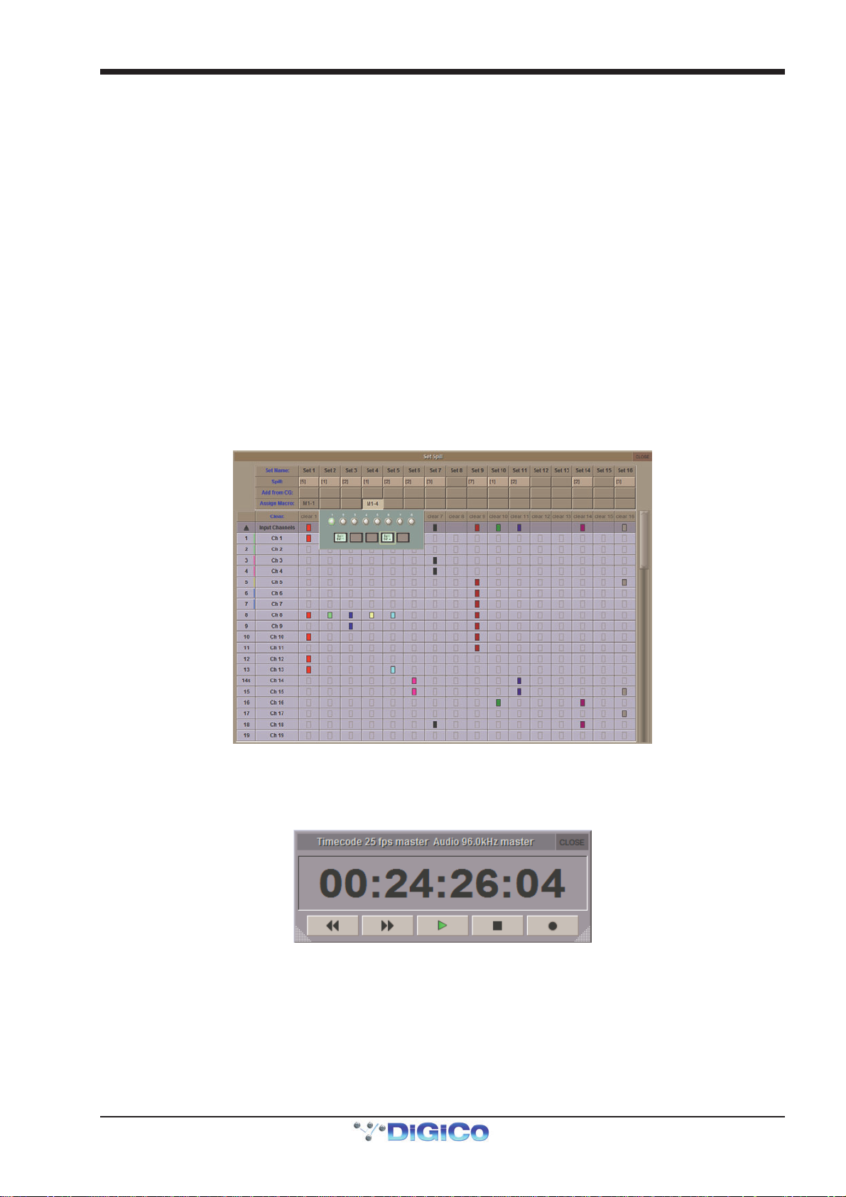
Chapter 2 - The Master Screen
2.3.4 Set Spill.................................................................................
Touching on Set Spill in the Layout menu brings up the Set Spill display, where channel Sets can be configured and spilled onto the console. A Set is simply a group of channels selected from across the console's layers, which can be 'Spilled' onto the worksurface together. They can be made up of a mixture of channel types, and need not have anything else in common. The main part of the display is navigated in the same way as the Channels List described above.
To create a Set simply choose a Set column and touch the boxes in that column for each channel you wish to include, expanding
the channel types as required. The boxes will all turn the same colour. The box in the channel type's parent rows will also turn the
same colour, indicating that some channels of that type are included in the Set. the number of channels included in the Set is
shown in the Set's Spill: box, above the channels display. Any channels which are included in a Gang are indicated by the
Gang's colour being displayed on the right-hand edge of the channel's number box (at the left end of its row in the channel
display).
To rename a Set, touch on its Set Name: box, type a new name on the on-screen or external keyboard, and press OK.
To add all channels from a Control Group, touch the Set's Add from CG: box and touch the appropriate CG button from the pop-
up which appears. The Spill: number will increment to indicate how many channels have been added.
To clear a Set, touch its Clear: box and touch Yes in the confirmation pop-up which appears.
Sets can be spilt directly from this panel, or assigned to a Macro. To spill a Set from this Panel, touch its Spill: box. A tick will
appear by the spill number to indicate that the channels are spilt. To assign the Set Spill to a Macro, touch the Set's Assign
Macro: box to bring up a display of the console's Macro controls; Now select a Macro button. The Macro's bank and position will
be displayed in the Set's Assign Macro: box.
The Set Spill Direction entry in the Faders tab of the Options menu defines how Sets are spilt onto the control surface.
Sets can be unspilt by pressing their Macro or Assign Macro: box, or by pressing the Layer button for the console section
where the set is shown.
The SD7 Set Spill panel
2.3.5 Transport Control..................................................................
Touching on Transport Control in the Layout menu brings up a display of the transport control of an external playback device.
Playback devices are controlled via the MIDI connector on the console's back panel. The incoming MTC is also displayed.
Note that control of external playback devices can be programmed within the Snapshots screen, as described later in this
chapter.
2-15
Page 50
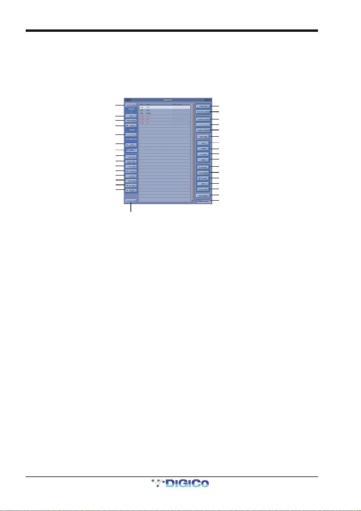
Chapter 2 - The Master Screen
n
O
O
Opens cont rol by MIDI panel
2.4 Snapshots Menu
Any number of Snapshots of the entire current console settings can be stored and recalled using the Snapshots panel. (This is
only limited by system memory)
These Snapshots can be independent or grouped with other snapshots.
The recall scope of the snapshot (how many controls it will affect when fired) can be set by controller or by channel.
To display the Snapshots panel, touch the Snapshots button at the top of the Master Screen.
Worksurface controls are detailed in Getting Started.
Opens Glob al scope panel
Opens snapshot notes panel
Adds current snapshot to group
Lock prevents snasphot update
Snapshot under control of sequence
duration in rec all times panel
Removes snaps hot from Prev/Nex t control
Shows indiv idual snapshot option buttons
pens indi vidual snapshot rec al l s cope panel
Opens group/auto-update scope panel
Opens snapshot crossfades panel
Opens snapshot recall times pane l
pens snapshot MIDI program change panel
Opens snapshot transport control panel
Opens snapshot MIDI list
Opens snapshot GPO panel
Inserts new snapshot after
selected (Green) snapshot
Duplicates selected (Green)
Updates current (Highlighted)snapshot
Updates all members of Snapshot Group
Updates selected (Gr een )sn apshot
Allows editing of multiple snapshots after selectio
Allows changing of order of snapshot list
Press and se lect snapshot to rename
Press to ope n R enumber panel
Press and se lect snapshot(s) to delete
Fires previous snapshot in list
Fires selected (Green) snapshot
Fires next snapshot in list
Undo firing of last snapshot
Activate snapshot fire by touching list
Activate snapshot Auto Update
Group Update Mode
Note - The current snapshot appears in the panel as the highlighted entry in the list. The snapshot name
displayed in green indicates that it is the selected snapshot on the worksurface and its name is indicated in
the display. The Fire button recalls this selected snapshot and highlights it in the screen list as the current
snapshot.
Note also that an 'update Waves only' button appears below the Scope buttons when Waves is active.
If the current snapshot shows an asterisk next to the number (eg. 001*) this indicates that a controller has changed since the
snapshot was fired.
If a Snapshot name appears in black in the list it is a standard Snapshot and if it appears in red or blue then it is a member of a
group of snapshots
2.4.1 Storing a Snapshot ...............................................................
When a snapshot is stored all the console settings are saved but when the snapshot is recalled its effect can be limited to certain
channels and controllers using the Global and Recall Scopes.
To store a snapshot of the current state of all the console controls, touch the Snapshot panel or worksurface Insert New button and a new snapshot will be inserted below the currently selected (green) snapshot. Alternatively, if the Touch To Fire function is active, touch an unused button in the list and a new snapshot will be added to the end of the list, then type a name for the snapshot.
Another method of creating a Snapshot is to press the Duplicate Selected button and this will create a copy of the selected (green) Snapshot below it.
Note - If Duplicate Selected is used, the Snapshot that is stored may not reflect the current state of the
console's controls - it will simply create a copy of the Snapshot that was selected when the button was
pressed.
2.4.2 Recalling a Snapshot ...........................................................
There are several ways to recall a snapshot:
1) Activate the Touch To Fire function using the button on the Snapshot panel and then touch the snapshot button you require.
2) The buttons on the Worksurface provide Scroll Up/Down buttons to change the selected snapshot named in the worksurface
display and listed on screen in green. The Fire button then recalls the assigned snapshot.
3) The worksurface Previous and Next buttons can be used to step up and down the list firing snapshots in consecutive order.
4) Snapshot firing can also be controlled by specific events on MIDI channel 16 (See Snapshots and MIDI).
5) Assign a Macro button to fire the Snapshot.
2-16
Page 51
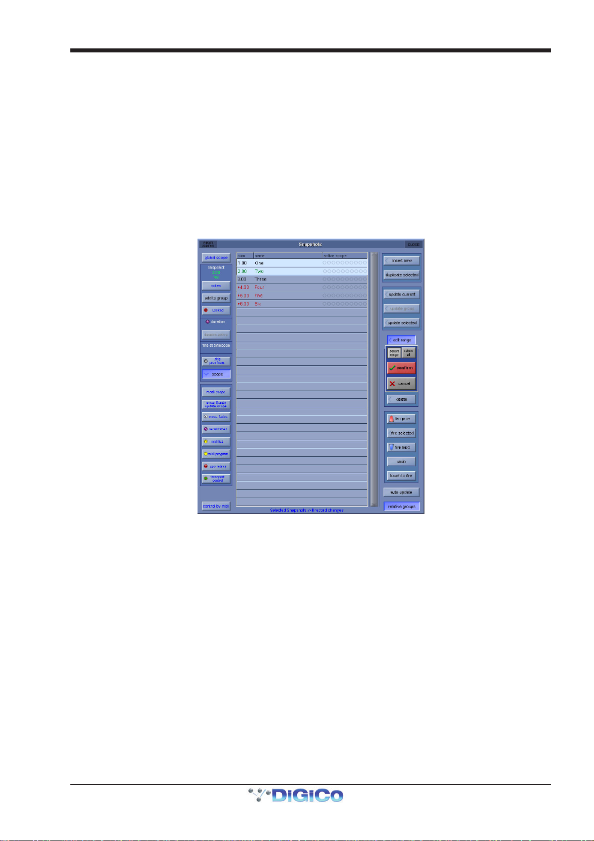
Chapter 2 - The Master Screen
2.4.3 Replacing a Snapshot ..........................................................
To update or change a snapshot, set the console controls as required and then touch the one of the Update buttons (Current,
Selected or Group)
Note - The Current snapshot is not necessarily the one whose name appears in the display on the
worksurface, this is the Selected snapshot. For a snapshot to be Current it must have been the last one that
was fired and be highlighted in the on screen panel's list.
2.4.4 Editing Multiple Snapshots ..................................................
Individual controller changes can be written to several snapshots simultaneously using the Edit Range button. This does not replace all of the data associated with the snapshot, just the elements that are changed at the time.
When the Edit Range button is pressed, a panel pops up allowing you to Select Range, Select All, or select individual Snapshots. You can now select the relevant snapshot(s) from the list.
If you press the Select Range button, touching the first and last snapshots in a range will automatically select all the snapshots in that range.
Once snapshots have been selected for editing, press the confirm button, or press cancel to cancel the Edit Range button.
With the Edit Range button active, pressing the Snapshot buttons does not fire the snapshots; it only selects them for editing.
The selection may be changed by pressing and releasing snapshot buttons at any time during the operation of the Edit command,
so a variety of controllers or routes may be changed in a variety of snapshots before completing the operation by pressing the Confirm button.
The Snapshots window may even be closed to gain access to other editable functions - In this case, a warning message will
appear to advise the user that they are still in snapshot edit mode.
While any Snapshot is selected, changes to any snapshottable controller, routing changes, and any changes to the Snapshot
Scope controls can be written to every selected Snapshot, overwriting the previous settings.
Pressing the Confirm button keeps the changes.
For example, if Snapshots 1 and 2 are selected and the input gain for channel 1 is changed, subsequent recall of Snapshots 1 or
2 will set channel 1’s input gain to the new value.
Only channels which are altered while the Edit command is active will be affected and only in snapshots that are selected at the
time.
Note - Snapshot Scopes and Crossfade Times can also be edited for multiple Snapshots using the Edit Range
function
2.4.5 Moving a Snapshot ...............................................................
If you wish the Snapshot list to appear in a specific order, you may change the order of the list by moving the entries. Touch the
Move button and then touch the Snapshot that you wish to move. You then touch the point in the list where the snapshot should
be moved to.
2.4.6 Renaming a Snapshot..........................................................
To rename a snapshot, touch the Rename button, then the name that you wish to change and enter a new name using the keyboard.
2-17
Page 52
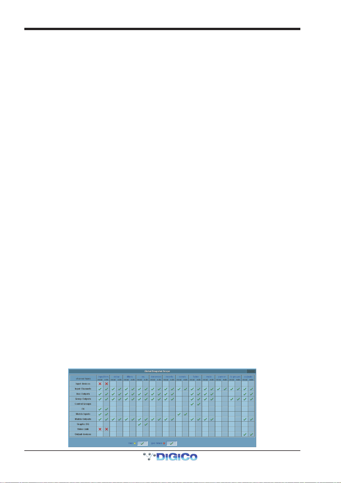
Chapter 2 - The Master Screen
2.4.7 Renumbering Snapshots......................................................
As snapshots can be inserted at any point in the list you may find that you wish to renumber part or all of the list. Press the Renumber button at the bottom of the snapshots panel and a new panel will open. Enter the range that you wish to renumber using the touch turn control or by touching the entry and typing and then enter the steps to renumber to (1.00 is the
default value). Then press the OK button and the list will be adjusted accordingly.
2.4.8 Deleting a Snapshot .............................................................
To delete snapshots, touch the Delete button and then Select Range or Select All. If you have pressed Select Range, touch
the Snapshots in the list that you wish to delete and then press Confirm. If you have pressed Select All, the complete list of
Snapshots will be highlighted and pressing Confirm will delete all Snapshots.
Note - To cancel a Delete operation before it has been confirmed, press the Delete button again.
2.4.9 Snapshot Undo......................................................................
When a snapshot is fired, a separate hidden snapshot of the complete console is stored before the fired snapshot has its effect.
If the Undo button is pressed, the hidden snapshot is fired using the same scope as the previously fired snapshot to undo its
effect.
2.4.10 Snapshot Groups ................................................................
A standard Snapshot (black entry in the list) is an independent snapshot of the current state of all the console controls.
A Snapshot can also be a member of a Group (red or blue entry in the list).
Making Snapshots members of a Group allows all members of that Group to be updated together according to the Group Update
mode that is selected.
To make a Snapshot a member of a Group, select the Snapshot in the list and press the add to group button on the left of the
Snapshot panel.
Note - Snapshots can only be members of the same Group if they are next to each other in the list. There can
be several different groups of Snapshots in one list.
If a Snapshot is a member of a Group, the colour of its entry in the list is determined by the current setting of the Relative Groups button in the bottom right of the Snapshots panel. This determines how the Group of Snapshots will be updated when Update Group is pressed.
Red entry in the list = Relative Update mode selected
Blue entry in the list = Non Relative Update mode selected
Relative Group Update Mode (Red entries in the list)
If Update Group is pressed when the relative groups button is active, all dB controls such as faders and aux sends will be updated relatively. This means that if a fader is moved by +10dB in one snapshot, the same fader will be moved by +10dB in all Snapshots that are members of the same group, irrespective of the original level of that fader. So +10dB will be applied to the stored level of that fader in all of the Snapshots in the group.
Non dB controls such as Dynamics times, EQ Frequency & Q and Pans will only be changed in members of the group that had the
same value for that control before it was moved. So, if one channel pan is in the same position in all the members of a group of
Snapshots and you change one of them and press Update Group in Relative mode then the same channel pan will change in the
same way in all the other snapshots that are members of that group. If however, any one of the Snapshots in the group has that
channel pan in a different position to the current Snapshot then this one will not be changed when you press Update Group.
Non Relative Group Update Mode (Blue entries in the list)
If Update Group is pressed when the relative groups button is not active then all controls behave in exactly the same way.
Changes are only applied to the other Snapshots in the group if the controls that are being changed had the same value as the
current Snapshot before the change was made. This is exactly the same behaviour as non dB controllers in Relative mode but in
this case all controls are included.
Group & Auto Update Scope
The behaviour of the Group Update function explained above is also dependent on the Global Auto Scope and the Group and
Auto Update Scope settings that can be set per Snapshot for different types of controls.
Pressing the Global Scope button at the top left of the Snapshot panel opens the following display:
2-18
Page 53
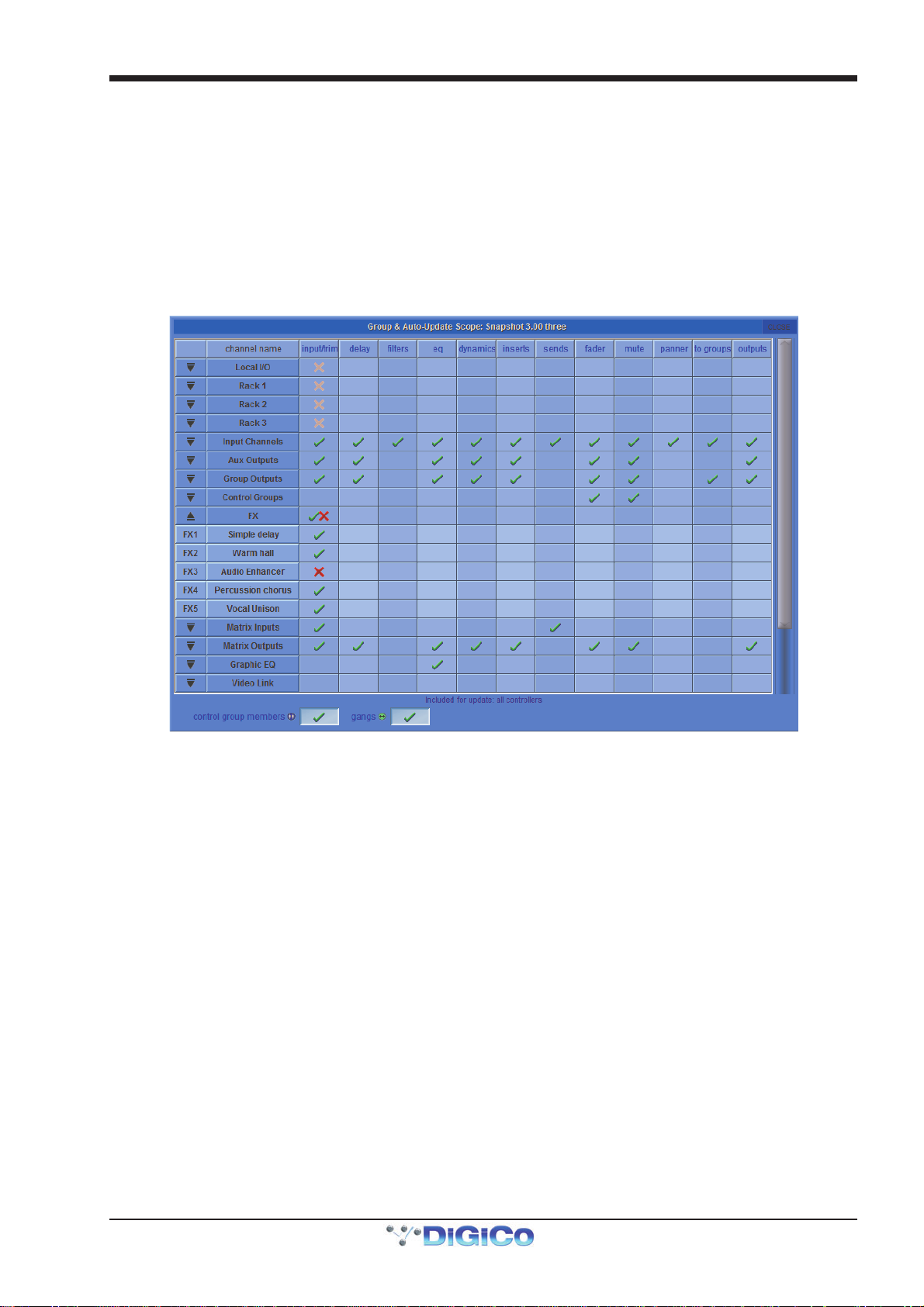
Chapter 2 - The Master Screen
Horizontal rows show the different sections of the console and the vertical rows show the Recall and Auto Update status for
each of the different types of control. A red X indicates not included and a green tick indicates included. These settings can be
changed individually by touching the X or tick symbols or by touching the name of a row or column to change all of its contents.
Recall Scope is dealt with in the next section but the Auto scope columns determine which controls will be included in the
automatic group update. Any elements that have a red X will not be updated in any snapshots when Update Group is pressed.
In the picture above the Input Devices (rack and local input sockets) are not included in the Auto scope so none of their gains or
phantom power can be updated using the Update Group function. All other elements are ticked and therefore can be included in
the Update Group function.
Note - If elements are included in the Global Auto Scope they can still be prevented from Group Updating by
the individual Snapshot's Group and Auto Update Scope.
Selecting a Snapshot in the list and pressing the Group & Auto Update Scope button opens the following panel:
This is similar to the Global Scope panel but represents the Group and Auto Update Scope for one individual snapshot which is
indicated by its name and number at the top of the panel.
The down arrows on the left of the panel can be clicked to expand the list to show and edit the status of individual sockets and
channels for each Snapshot.
Changes in Control Group membership and ganging can also be included or excluded using the tick boxes at the base of the panel.
In the picture above the Audio Enhancer input trim has been excluded from the Group Update in this particular Snapshot.
Note - When using Snapshot Groups it is advisable to set the Global Auto Update scope before attempting to
change the update settings for each individual Snapshot. Use of the Global Scope alone probably offers
quite sufficient control for most common applications.
2-19
Page 54
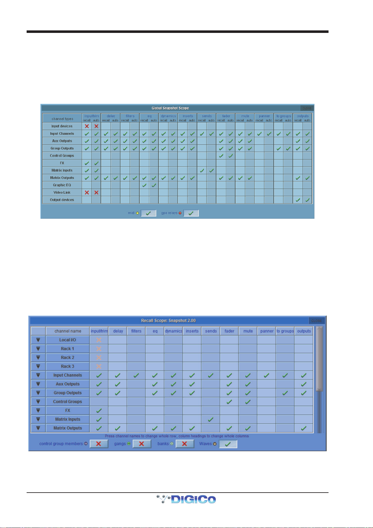
Chapter 2 - The Master Screen
2.4.11 Global Recall Scope..........................................................
When a snapshot is stored all the console settings are saved but when the snapshot is recalled its effect can be limited to certain
channels and controllers.
Note - All elements of console channels and several other features such as Graphic EQ and Effects have their
own SAFE settings. If any of these SAFE settings are active then the relevant controls cannot be affected by
any Snapshots. This is in addition to the Global Scope settings described here.
Pressing the Global Scope button expands the panel to display and edit the scope for all snapshots.
Horizontal rows show the different sections of the console and the vertical rows show the Recall and Auto Update status for
each of the different types of control. A red X indicates not included and a green tick indicates included. These settings can be
changed individually by touching the X or tick symbols or by touching the name of a row or column to change all of its contents.
The Recall scope columns determine which controls will be included in the Snapshot recall. Any elements that have a red X will not be recalled in any snapshots.
In the picture above the Input Devices (rack and local input sockets) are not included in the Recall scope so none of their gains or
phantom power can be changed by firing Snapshots. All other elements are ticked and therefore can potentially be changed when
a Snapshot is fired.
Note - If elements are included in the Global Recall Scope they can still be prevented from recall by the
individual Snapshot's Recall Scope.
2.4.12 Individual Snapshot Recall Scope ...................................
Selecting a Snapshot in the list and pressing the Recall Scope button opens the following panel:
The controls that are included in each of the Recall Scope columns can be seen at the bottom of the panel when any of the entries
are changed and are as follows:
Controllers
Input/Trim (Local I/O and Racks) - analogue gains, switches and phantom power
Input/Trim (Input Channels) - input routes, digital trim, phase, channel name and tubes
2-20
Page 55

Chapter 2 - The Master Screen
Input/Trim (Aux Outputs/Group Outputs/Matrix Outputs) - digital trim, phase, delays, buss name and tubes
Input/Trim (Matrix Inputs) - input routes, matrix input name and tubes.
Delay (All channel types) - Channel delay
Filters (All channel types) - HPF and LPF
EQ (All channel types) - all controllers except channel HPF and LPF.
Dynamics (All channel types) - all controllers except stereo link.
Inserts (All channel types) - Insert Send & Return routes and ON/OFF switch
Sends (Input Channels) - Aux send levels, ON/OFF & PRE/POST switches and Aux pans
Sends (Matrix Inputs) - Matrix send levels and switches
Fader (All channel types) - channel fader.
Mute (All channel types) - channel mute
Panner (Input Channels) - channel pan
To Groups (Input Channels) - Input Channel to Buss routing switches
To Groups (Group Channels) - Group to Group routing switches
Outputs (Input Channels) - Direct output routes, direct gains and ON/OFF switches
Outputs (Aux Outputs/Group Outputs/Matrix Outputs) - Output routes and gains
Outputs (Local I/O and Racks) - analogue output 10dB pads and AES SRC switches.
Misc
Control Group Members - Control Group label and a complete list of each group’s members.
Gangs - Channel gang members.
Banks - Current assignment for all controllers and selected bank on the worksurface.
Note that if Waves is active, a Waves scope button is also shown.
The down arrows on the left of the panel can be clicked to expand the list to show and edit the status of individual sockets and
channels for each Snapshot.
2.4.13 Snapshot Recall Times.......................................................
In additional to being fired manually, snapshots can be timed to fire automatically in sequence. This is done in the Snapshot Recall Times panel, opened by pressing the scope>recall times button on the left hand side of the Snapshots panel.
Each snapshot can be given a recall at time (the timecode value at which the snapshot will fire) and a duration (the time lapse before moving onto the following snapshot). Both the duration and recall times must be activated by ensuring that their Active column is ticked. The smallest time units can be switched between 1/100ths of a second and frames using the duration display buttons in the bottom right-hand corner of the panel.
The first snapshot can be fired manually in the main Snapshot window, if no specific recall at time is set. When this snapshot is fired, the next snapshot in the list will automatically be fired after the set time has elapsed and a progress bar in the snapshot's entry in the Snapshots panel will show the time remaining until the snapshot is fired. Pressing the duration active button while the progress bar is moving will halt the process. The recall at time overrides any active duration time.
2-21
Page 56
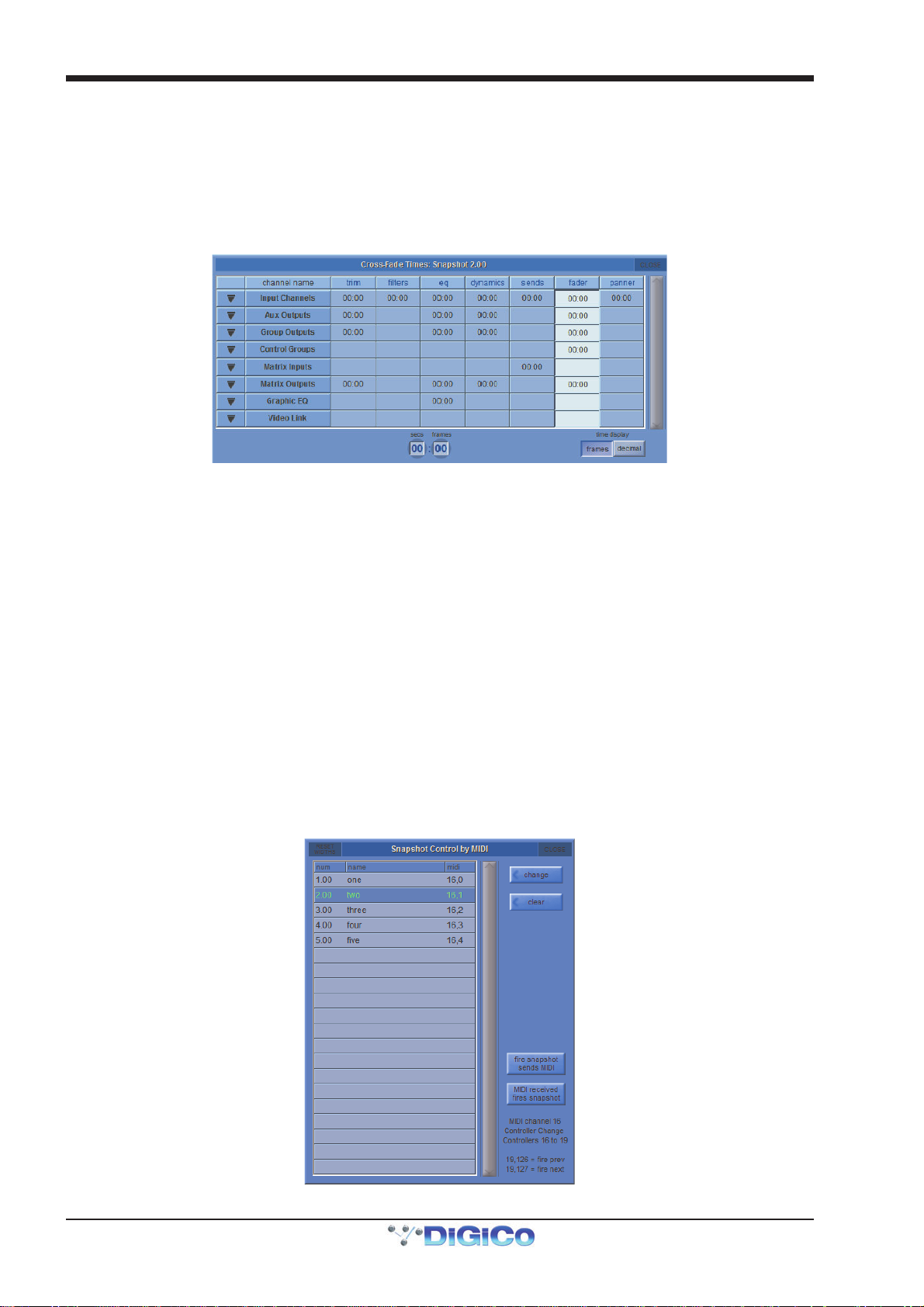
Chapter 2 - The Master Screen
2.4.14 Snapshot Crossfades ..........................................................
A crossfade time which is measured in seconds and frames can be applied to different controls in a Snapshot by adjusting the
Crossfade Time in the Cross Fades panel. This crossfade occurs as you go into the Snapshot.
Select an individual time by touching it or select a column or row by touching its heading. Then enter a time in the Secs/Frames
boxes at the bottom of the panel. Either touch and type or use the Touch Turn rotary to enter a figure.
Different Crossfade times can be applied to input trims, filters, EQs, dynamics, sends, faders and pans.
The down arrows on the left of the panel can be clicked to expand the list to show and edit the status of individual channels for
each Snapshot so different Crossfade times can be applied to different channels as well.
A value of zero switches it off.
2.4.15 Snapshots and MIDI ............................................................
There are two separate areas of MIDI control:
1) A snapshot can have a MIDI Message attached to it, and will output that MIDI when fired. The MIDI message must be created in
either the Scope>MIDI Program panel or the Scope>MIDI List panel.
2) The firing of snapshots can be controlled by incoming MIDI messages on channel 16, and can cause these same messages to
be output in addition to any MIDI List data contained in the snapshot. The specific MIDI messages that are being responded to can be edited in the Snapshot Control By MIDI panel, accessed via the
Control By MIDI button.
To change the default message for any particular snapshot, select the snapshot and press the Change button to select a
specific available controller number. The Clear button will remove the existing message completely. The MIDI Received Fires Snapshots button allows the Snapshot system to respond by default to the following incoming MIDI
messages:
General Purpose Controller 16; Values 1 to 127 will fire snapshots 1 to 127
General Purpose Controller 17; Values 0 to 127 will fire snapshots 128 to 255
General Purpose Controller 18; Values 0 to 127 will fire snapshots 256 to 383.
General Purpose Controller 19; Values 0 to 125 will fire snapshots 384 to 509.
General Purpose Controller 19; Value 126 will fire the previous snapshot in list.
General Purpose Controller 19; Value 127 will fire the next snapshot in list.
When active, the Fire Snapshot Sends MIDI button causes the above messages 1 to 509 (or customised versions - see below) to be sent whenever a snapshot button is pressed. Previous and Next buttons do not output MIDI messages of their own.
2-22
Page 57
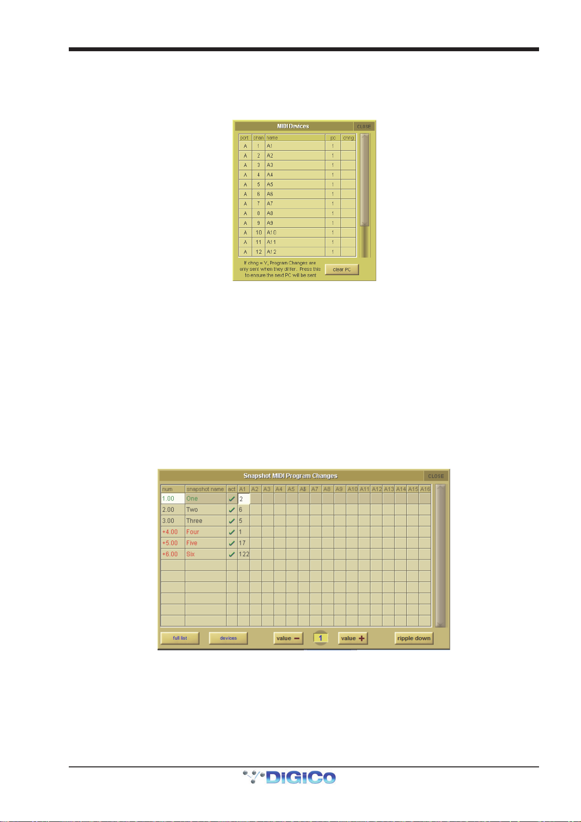
Chapter 2 - The Master Screen
2.4.16 MIDI Devices........................................................................
If you intend to send MIDI to external devices it is advisable to first define your receiving devices - this will make the programming
of MIDI messages in Snapshots easier to achieve.
Press either the Scope>MIDI Program or the Scope>MIDI List button and then press the Devices button - the following panel
will open:
The SD Console's built in MIDI port is referred to as Port A in the Port column. Set the receiving MIDI channel and name for each
of your receiving devices and set 1 or 0 in the PC column according to whether the device uses 0-127 (0) or 1-128 (1) for its data
values. If you don't know this piece of information then leave the setting as 1.
The column marked Chng determines whether Program Changes are only sent when they are different to the last sent message
(Y) or whether they are always sent irrespective of the last message sent. This would be useful if there was no need to change
the program on the receiving device and if you did this it might interrupt the signal passing through the receiving device as its
program changes.
The Clear PC button at the bottom of the panel ensures that the next message will be sent. This has defined your devices for later use and the panel can now be closed.
2.4.17 MIDI Program and MIDI List ...............................................
The Snapshot MIDI Program Changes panel, accessed via the midi program button has a column for each of the 16 MIDI channels on Port A and a row for each existing Snapshot. Touch and type, use the value up/down buttons or enter a value using the Touch Turn rotary control for each program change that you wish to send with each snapshot and ensure that the act (active) box is ticked for each relevant Snapshot. With the ripple down button active, entries will be copied to all consecutive following Snapshots that have the same value as the one which was changed or have no value. Once entered, this MIDI information will be sent when the Snapshot is fired.
If MIDI program change messages have been entered in this way they will also appear in the Scope>MIDI List panel which
allows entry and editing of other types of MIDI message.
There are columns for the midi device name (mentioned in the last section), the MIDI Port, MIDI Channel, type of command and
two data values.
Note - If you have already defined MIDI Devices, selecting one of these in the MIDI Device column will automatically enter the Port and MIDI channel that you have previously entered for that device.
2-23
Page 58

Chapter 2 - The Master Screen
If you want to send multiple MIDI messages with a single Snapshot, use the Insert button to add extra lines for message entry.
You can then configure the message by selecting each column in turn, and using the value controls to the right of the list. Below
the value controls is a key for the command column.
To test the MIDI message without firing the Snapshot, press the Send button - the display at the bottom right of the panel shows
the presence of incoming and outgoing MIDI messages.
MIDI messages can also be automatically entered into the list by generating the required message from the external MIDI device, sending this to the console's MIDI In and pressing the Capture button.
2.4.18 Snapshot GPO Relays
The Snapshot GPO relays panel allows the state of each GPO to be set when a snapshot is fired.
The Global Recall scope for each GPO can be set by touching the appropriate box at the top of the column.
2-24
Page 59

Chapter 2 - The Master Screen
2.4.19 Surface Offline & Snapshot Editing (Not SD11) ................
In the Snapshot section of the console worksurface there are 2 buttons labelled Surface Offline and RTN To Audio. When pressed and held, the Surface Offline button stops the communication between the worksurface controls and the audio
engine - this means that anything that is done on the surface of the console will have no effect on the audio passing through the
console.
Pressing the RTN To Audio button will reconnect the surface controls to the audio engine ignoring any worksurface changes that
have been made since the surface was put Offline and returning the console to its state before the Surface was put Offline.
Important Note - if the Surface Offline button is pressed, worksurface changes are made and the Surface
Offline button is pressed a second time, the changes that have been made on the worksurface will immediately applied to the current audio - be careful with this function...!
The main purpose of the Surface Offline and RTN To Audio buttons is to enable Snapshots to be edited with the worksurface
offline so that any Snapshot can be previewed, adjusted and updated without affecting the current audio.
While Surface Offline is active any of the Snapshot functions already described can be used.
As an example, if you are currently in Snapshot number one and wish to check or edit Snapshot number two you should:
1) Press and hold the Surface Offline button and the audio will continue normally.
2) Scroll down and fire Snapshot two to see its settings on the worksurface.
3) Edit the settings for Snapshot two and Update either Current or Selected according to requirements.
4) Press the RTN to Audio button to automatically put the surface back online and back in Snapshot one.
2.4.20 Auto Update.........................................................................
The Auto Update button in the Snapshots panel activates automatic updating of the current Snapshot whenever a control is
adjusted. The current Snapshot will be updated without using the Update Current, Selected or Group functions. The elements of
the Snapshot that are automatically updated is dictated by the Group and Auto Update Scope settings that are described in the
Group Snapshots section of this chapter.
Note - In view of the potential for changing Snapshots without active manual intervention, it is probably
advisable to leave this function OFF unless you are absolutely certain that you require it.
2.4.21 Snapshots & MTC ................................................................
Snapshots can also be programmed to send MMC messages, allowing control of external playback devices. Within the snapshot
scope section, press the transport control button. This opens the Snapshot Transport Control panel. The panel lists all
current session snapshots and allows entry, per snapshot, of the following MMC commands.
PLAY: Basic Play command. External device will play from current location
play from: External device will play from specified time value
play to: External device will stop when the specified time is reached.
locate to: External device will Locate to specified time.
STOP: Basic Stop command. External device will stop.
Commands can be sent via MIDI, selected at the bottom of this panel.
NOTE : Correct MMC operation relies on a correctly configured MIDI system, with MTC from the external
device connected to the console MIDI Input. If this MTC connection is not present, the MMC snapshot system
will not work.
A Transport Control panel is also provided in the Layout Menu. This provides a MTC readout of incoming MTC, and allows direct
control of the external device.
2-25
Page 60

Chapter 2 - The Master Screen
2.4.22 Snapshot Notes ...................................................................
Pressing the notes button (towards the top left-hand corner of the main Snapshots panel) opens a notes panel, displaying any
notes associated with the current Snapshot. This panel stays open whenever the notes button is active, switching to the next
Snapshot when it is fired. The selected and next snapshots are shown below the text box.
To add notes, simply touch inside the notes space in the centre of the window and type your notes. To clear the text, touch the
clear button in the top left-hand corner of the panel.
To format the text or background, touch the style button (next to the clear button) to open the Notes Style panel:
The text can be formatted using the text size controller and bold, italic and underline buttons in the left side of the panel. To
change the colour of the text or background, select either the text colour or background button in the left side of the panel,
touch inside the colour palette in the centre of the panel, and adjust the brightness using the brightness controller. The selected
colour is displayed above the brightness controller.
Note that text defaults to minimum brightness (black), and the background to maximum (white). You may
therefore need to move the brightness controller towards the middle in order to see the colour content.
You can save your selected colour as one of the twelve custom colours in the right of the panel. To do this, simply select the
add colour button and touch inside the desired custom colour box.
You can also copy styles from other snapshots using the copy from snapshot controls beneath the main colour palette. Use the
up and down arrows to move through the snapshot list – the snapshot whose style is currently displayed is shown in the copy
from snapshot text box.
Note that copying a style from another snapshot will overwrite the current style.
2.4.23 Snapshot Locked ................................................................
Note: Only available on non Theatre software versions
To lock a Snapshot and prevent it from being updated, select the Snapshot and then press the Locked button on the right of the
panel. It can be unlocked in a similar way.
When a Snapshot is Locked, it cannot be updated using update selected/current or deleted.
2-26
Page 61

Chapter 2 - The Master Screen
2.5 Options
The Options menu includes a variety of SD system preferences, grouped into nine tabs. Most functions are described fully within
the display. Each function’s button displays Yes in purple to indicate that it is active, and No in grey to indicate that it is inactive.
Note that if Waves is enabled, the Options menu is located in the Setup drop-down menu. See the appendices
for more details.
2.5.1 Surface ..................................................................................
The Surface tab includes settings related to the console screen, buttons and encoders:
Touch Keyboard
This option defines whether or not the on-screen keyboard appears when a name box is touched. It is active by default.
Large LCD Names
This option allows the names in the LCD displays to be displayed in a larger font, either with the gain value and solo buss (with
dBs) or as the channel only (name only). It is inactive by default.
Round to whole dBs
Fractional dB values are rounded to the nearest integer value.
Auto Expand EQ
This option defines whether or not the EQ display opens when an EQ is adjusted. It is active by default.
Auto Expand Dynamics
This option defines whether or not the dynamics display opens when an dynamics is adjusted. It is active by default.
Auto Expand Time
This pot, located to the right of the Auto Expand EQ and Dynamics options, defines how long the EQ and dynamics displays
remain open after the parameters within them are adjusted. The current setting is displayed in seconds, below the pot. Touching
the pot assigns it to the Touch-Turn encoder.
Aux To Masters (SD7 Only)
This option allows the all of the aux send levels for one channel to be assigned to the Lower Master faders by pressing that
channel’s lower aux button (the button in the third row of aux encoders below the Channel strip panel). This is useful if, for
example, all of the fold-back sends from one channel need to be adjusted. The function is inactive by default. If there are more
than twelve auxes in the session, the Lower master bank buttons are used to move between banks of twelve auxes.
Note that the number of auxes is not divisible by twelve, some faders within the last bank half banks will
retain their original function, as indicated by their LCD buttons.
Global Quick Select (SD5, SD9, SD11)
This option defines whether the Quick Select selection will be the same for every bank on a Surface. Note, on the SD5, the
selection will be different between the left and right surface.
Display Snapshots Overview
This option allows a floating copy of the Snapshots list to be displayed in the overview screen, for the viewing or triggering of
Snapshots.
Global 2nd Function
This option defines whether the 2nd function button affects just the current surface (no) or all surfaces on the console (yes).
Auto-cancel 2nd Function
This option defines whether or not active 2nd Function buttons are cancelled after the time defined in the auto-cancel time pot
to its right. It is inactive by default. Touching the pot assigns it to the Touch-Turn encoder.
2-27
Page 62

Chapter 2 - The Master Screen
Note that both the auto-expand time and auto-cancel time values are set on the console and are not saved as
part of the session file.
Engine A/B Switches Audio (SD7 Only)
This option concerns the Engine button in the top left-hand corner of the SD7's master section, shown below, which is used for
switching the SD7 to the redundant engine. When this function is inactive, the Engine button switches just the console controls;
when this function is active, the Engine button also switches the audio processing. This function is inactive by default.
2.5.2 Faders....................................................................................
Fader Assigns Channel
This option allows a channel to be assigned to the worksurface channel controls whenever its fader is touched. It is inactive by
default.
Note that when this option is active, accidentally touching a fader will assign it to the worksurface controls.
Fader 0dB Detent
This option defines which controls have a detent at 0dB. Options are Inputs, Outputs, Graphic EQ (default) and CGs.
Fader Touch Control
This option defines whether or not a fader moves when it doesn't detect a touch. Options are Free (fader moves freely) and Protected (fader is protected from moving without touch).
Note that this setting is set on the console and is not saved as part of the session file.
CG Faders control Aux Sends
If this option is set to Yes, whenever 'Aux to Faders' is activated (by any means), the Control Group faders jump to the middle and
become +/-18dB trims for the selected aux send, on all channels which are members of the Group. The fader for Control Groups
which have no members will simply close and do nothing. CG Mutes and Solos continue to operate as normal.
Set Spill Direction (SD5, SD7, SD8, SD9, SD10)
This option defines the way in which Sets are spilled onto the worksurface: L Vert places them on the left side, creating as many
banks as are required to spill all the channels in the Set; R Vert does the same on the right side; Horiz places the first 24
channels across both sides of the console before creating as many banks across both sides as are required to spill all the
channels.
2-28
Page 63

Chapter 2 - The Master Screen
2.5.3 Solo........................................................................................
The Solo tab includes settings related to the console’s solo functions:
Solo Displays Insert
This option defines whether or not the display of any internal FX or Graphic EQ inserted on a channel is opened when that
channel’s solo button is pressed. The Graphic EQ panel can only be displayed on the Master screen. It is active by default.
Solo Assigns Aux to Faders
This option defines whether or not the send levels to an aux channel are assigned to the channel faders when that aux channel’s
solo button is pressed. It is active by default.
Solo Assigns Aux to Rotaries
This option defines whether or not the send levels to an aux channel are assigned to the top row of aux encoders when that aux
channel’s solo button is pressed. It is active by default.
Aux to Faders includes Pans
This Option defines whether or not the pan assignment for the under screen rotaries will become the stereo aux pan when a
stereo aux is soloed if Solo Assigns Aux to Faders is active.
Solo Assigns Channel
This option defines whether or not a channel is automatically assigned to the channel worksurface controls when that channel’s
solo button is pressed. It is active by default.
Solo Reverts to Output
This option defines what happens if an output channel solo is active when an input channel solo is then activated and deactivated. When this option is active, deactivating the input channel solo will return the solo buss to the output previously in solo
mode. When this function is inactive, deactivating the input channel solo will leave all solos inactive.
The option is only available if the solo buss is in single mode. The option is inactive by default.
2-29
Page 64

Chapter 2 - The Master Screen
2.5.4 Delays ....................................................................................
This tab is used for defining the delay units used in the Setup panel of Input channels, Output channels and fx channels (fx
units). The options are seconds (default), feet, metres, bpm and frames.
Note that these options are also displayed to the right of the numeric keypad opened by pressing the delay's
keypad symbol.
2.5.5 Disable...................................................................................
This tab is used for disabling worksurface buttons, in order to prevent accidental changes if they are not being used. This
function does not affect on-screen operation of the functions: If the Panel will show the options relevant to your console.
2-30
Page 65
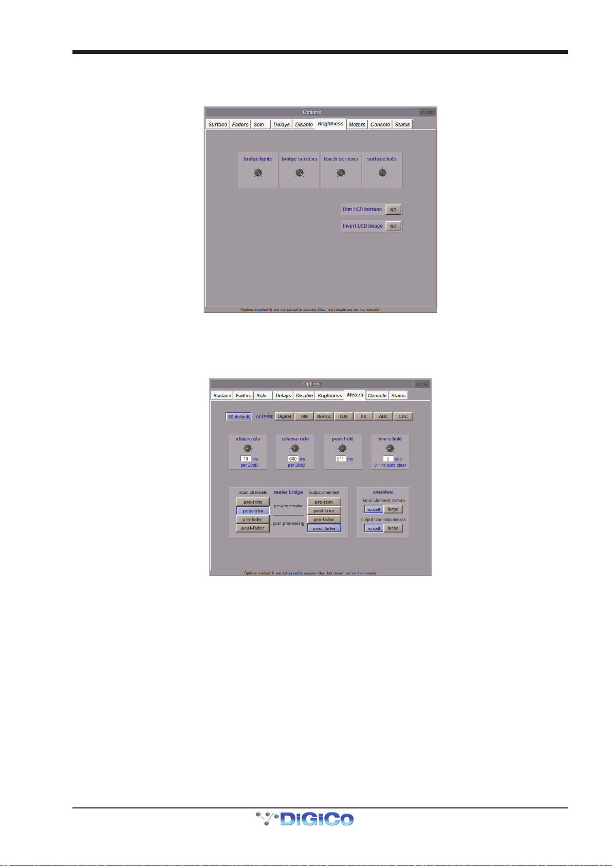
Chapter 2 - The Master Screen
2.5.6 Brightness..............................................................................
The Brightness tab is used for adjusting the brightness of the console’s bridge/Lil lights, screens and surface leds. Touching each pot assigns it to the Touch-Turn encoder.
The SD5 and SD7 console’s LCD buttons are not controlled by the surface leds pot but by the Dim LCD buttons and Invert
LCD Image options towards the bottom of the screen. Note that the dimming option only dims the brighter LCD colours.
2.5.7 Meters ....................................................................................
The Meters tab includes settings related to the console meters:
The four pots across the middle of the panel affect the attack and release reaction time (attack rate and release rate), the peak hold time and the overs hold time. The current setting for each is displayed in either milliseconds or seconds, below each pot. Touching each pot assigns it to the Touch-Turn encoder. The row of buttons above the pots provide access to a number of preset meter configurations, including the SD default and a number of PPM formats.
Note that when the overs hold time is set to 0, the hold time is set to infinite, not 0. The overs lights will therefore remain lit until they are manually cleared.
Note also that if you activate a metering preset and then edit it, the button for the preset on which the setting
are based will still appear selected.
The point being metered within the channel is set using the eight buttons in bottom left of the display. The input channel meters are adjusted using the buttons on the left, and the output channels are adjusted on the right. The options for each are pre-trim, post-trim (pre-processing), pre-fader (post-processing) and post fader. The default setting is post-trim for input channels, and post-fader for output channels. The currently selected button is displayed in purple.
The Overview area in the bottom right of the display allows the size of Input and Output Meters to be set: small or large.
Note that the settings in the bottom half of the display affect the meters on the worksurface, not the onscreen meters.
2-31
Page 66

Chapter 2 - The Master Screen
2.5.8 Console..................................................................................
The Console tab includes settings related to the console’s startup procedure:
Load Startup Session
This option allows the startup session to be automatically loaded on system start up. When not selected, the desk will always
start up in the default state.
Save Startup Session
This option allows the startup session to be automatically saved when quitting. When not selected, the desk will always start up in
the same state.
Auto-Save Recovery Session
This option enables an auto-save function, which saves the active .ses file regularly, in case it needs to be recovered. The time
between auto-saves is defined using the save every pot to the right of the option's button.
Default Positions
This option allows all windows to be set to their default positions on next launch.
Enable Waves MultiRack
This option enables Waves features. Waves is an optional extra which provides a set of Waves plug-ins in addition to the
console's own fx units.
Note: This option should not be enabled unless the console has Waves hardware and software installed.
Contact DiGiCo if you are interested in purchasing Waves.
Enable Optocore
This option allows optocore connections to be switched off if not in use. You can have both optocore loops OFF, or you can
enable Loop 1, Loop 2 or Both.
Enable Console Network
This option activates networking for remote control PCs and consoles and is explained in the Network and Mirroring section
Note that Enable Waves MultiRack and Enable Console Network both require a restart for changes to take effect.
Mirroring Mode
This option defines the way control is assigned between networked consoles and is explained in the Network and Mirroring
section.
Single Engine Only (SD7 Only)
When active, this option allows two SD7's with only one engine to be mirrored together.
2-32
Page 67

Chapter 2 - The Master Screen
2.5.9 Status .....................................................................................
The Status tab defines whether console status notifications are displayed. All functions are active by default.
Display System Status Indicators
This option defines whether or not the Status display is open. This display provides constant monitoring of various elements of the
console’s systems. The indication box to the right of each element displays a green OK when that element is running correctly, a
red error when that element is malfunctioning, and a blank grey box when that element is not relevant. Touching any indication box
will bring up the appropriate Diagnostics page, if there is one.
Display System Alerts
This option defines whether or not system warnings are displayed. The time for which alerts are displayed is adjusted via the
message display time pot, located towards the bottom of the window. The current setting is displayed in seconds, below the pot.
Touching the pot assigns it to the Touch-Turn encoder.
Display Overs Alerts
With this option active, whenever an input or output over-indicator comes on, the Signal Overs panel is displayed showing
details of the signals involved and their channels. Touching an entry in the Signal Overs list brings the channel to the surface to be
adjusted. The Signal Overs panel also duplicates the Clear Over Indicators button.
Note that the Signal Overs panel can also be opened using the Signal Over Indicators option in the System
menu.
Display Messages until acknowledged
With this option active, any system alert will remain on the screen until cancelled by the user.
2-33
Page 68
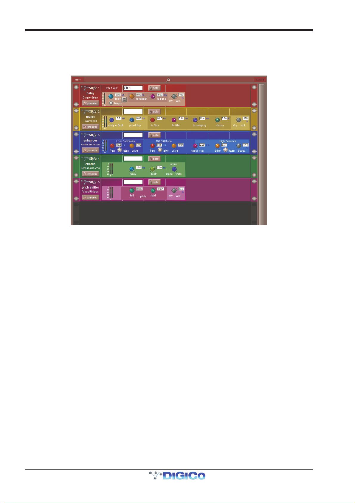
Chapter 2 - The Master Screen
2.6 FX
2.6.1 The Master FX Display..........................................................
Selecting the fx menu button in the master screen opens the master fx display, which shows all of the currently assigned fx units
in a single rack. Touching any control in this display allows adjustments to be made using the worksurface Touch Turn controls.
It is also possible to create and delete modules from this display:
To create a new module, click on the New button in the top left-hand corner of the fx window to bring up the fx Presets display,
then select the appropriate preset in the usual way. Routing to fx modules is then performed in the channel Outputs display.
To delete a module, click on the fx presets button on the module, and deselect the preset in the fx Presets display which appears.
A number of factory presets are provided, and these provide the basis for any user-adjusted presets. Factory presets are
indicated by the presence of a red padlock in the lock column on the right, and are described below. These include stereo FPGA
reverbs and other effects such as delays, choruses, pitch shifters and audio enhancers.
Once an effects preset has been adjusted, it can be saved, either as a new preset or as an updated version of the preset that
has already been created, to prevent the changes from being lost:
To lock the preset, activate the edit name button and touch the preset’s lock column. A grey padlock appears, indicating that the
preset is now locked. Touching the lock again with edit name active unlocks the preset. All master presets are locked and
cannot be unlocked. Master presets can be distinguished from user presets by the red colour of their padlocks.
Note - that factory preset group names can be edited, even though the presets themselves cannot.
Once an effects preset has been assigned, the fx output button in the channel strip recalls the preset’s controller display. In the
case of Input channels, once an effects preset has been assigned, the preset’s display can be recalled by touching the pan area
of the channel strip. The fx Presets display can then be recalled by pressing the fx presets button within the controller display.
Each FX unit can be safed by pressing the safe button at the top of its display. The channel’s name and output are also shown at
the top of the display, and each effect displays its input and output levels in meters in the left-hand side of the controller.
Note On SD7 up to 16 Stereo Reverbs and additionally up to 32 other effects (dependent on type) can be used at
any one time.
On SD5 up to 24 FX can be used with maximum of 16 Stereo Reverbs
On SD10 up to 16 FX Can be used
On SD8, up to 12 FX can be used
On SD9, up to 8 FX can be used
ON SD11, up to 6 FX can be used (4 on Standard SD11)
Note - If Presets are greyed out in the presets list this means that the maximum number of an FX type has
been reached
2-34
Page 69
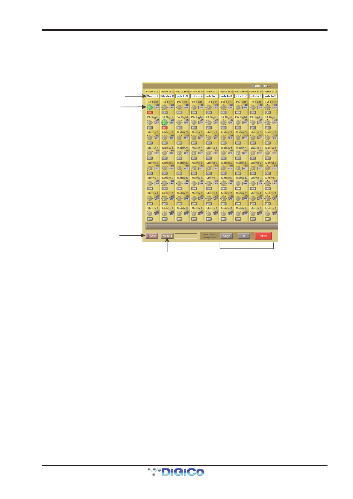
Chapter 2 - The Master Screen
2.7 Matrix Menu
2.7.1 The Matrix Panel ..................................................................
Touching the Matrix menu opens the Matrix Inputs panel, which allows matrix inputs to be selected and the level of each input to each output to be set. Each column of the display represents an input to the matrix, and each row represents an output. Each pot within the display trims the signal coming from the input for that column, going to the output for that row.
Matrix Input Routing
Matrix Crosspoint
Level Control
Matr ix Snapshot
Safe control
Matrix Preset Control Touch-turn assignments
The top of each input column displays the input’s name, and the label above each trim pot displays the pot’s output. Touching any
trim pot assigns it to the Touch-Turn encoder; pots lighten and are ringed green to indicate that they have been assigned. Multiple
pots can be assigned simultaneously, in which case the encoder alters all assigned pots by the same amount, regardless of each
pot’s position. The value of each pot is displayed in dB to its right. Sends are switched on using the Touch Turn control's button;
the display shows OFF in grey when it is off, and ON in red when switched on. Turning a pot automatically switches it on.
There are three touch-turn assignment buttons at the bottom of the display. The all button assigns all the trim pots to the Touch-Turn encoder; individual pots can then be deselected by touching them. The clear button clears all the pots from the touch-turn encoder. Activating the single button prevents multiple trim pots from being assigned to the encoder simultaneously.
Note that the all function can still be triggered when the single function is active.
2-35
Page 70
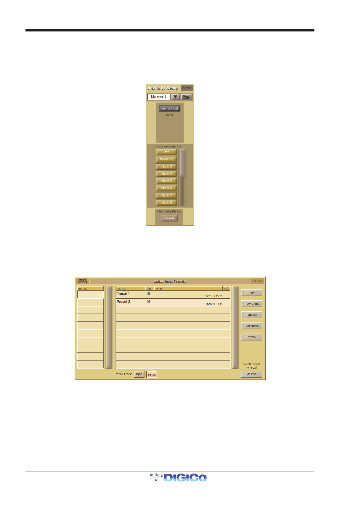
Chapter 2 - The Master Screen
Matrix input signals are selected in the Setup display, accessed by touching the text box at the top of each matrix input column.
At the top of the Setup display, there is a text box which can be used for renaming the matrix input. Below that, there is a matrix
input routing button which opens up a routing display. Routing displays are described in the Getting Started Section.
Below the routing button, there is a scrollable list of buttons displaying the names of all the other matrix inputs, under the heading
copy settings from, used to copy matrix settings between input columns. To copy the level and on/off status of each send from
one column to another, simply touch the button for the input column from which you want to copy settings.
The Matrix Input Presets panel is opened using the presets button located at the bottom of a matrix input Setup display and
also at the bottom of the Matrix panel. Preset panels are described in full in the Getting Started section. To include input routes in
the preset recall, make sure the input button at the base of the screen is active. To include trim pot levels and on/off buttons,
make sure the sends button at the base of the screen is active. The chs column of the display indicates the number of channels
included in the preset, and presets can be named – by default, Presets are named after input signal 1.
The safe button at the bottom of the Matrix panel protects the matrix settings from being overwritten by a snapshot recall.
2-36
Page 71
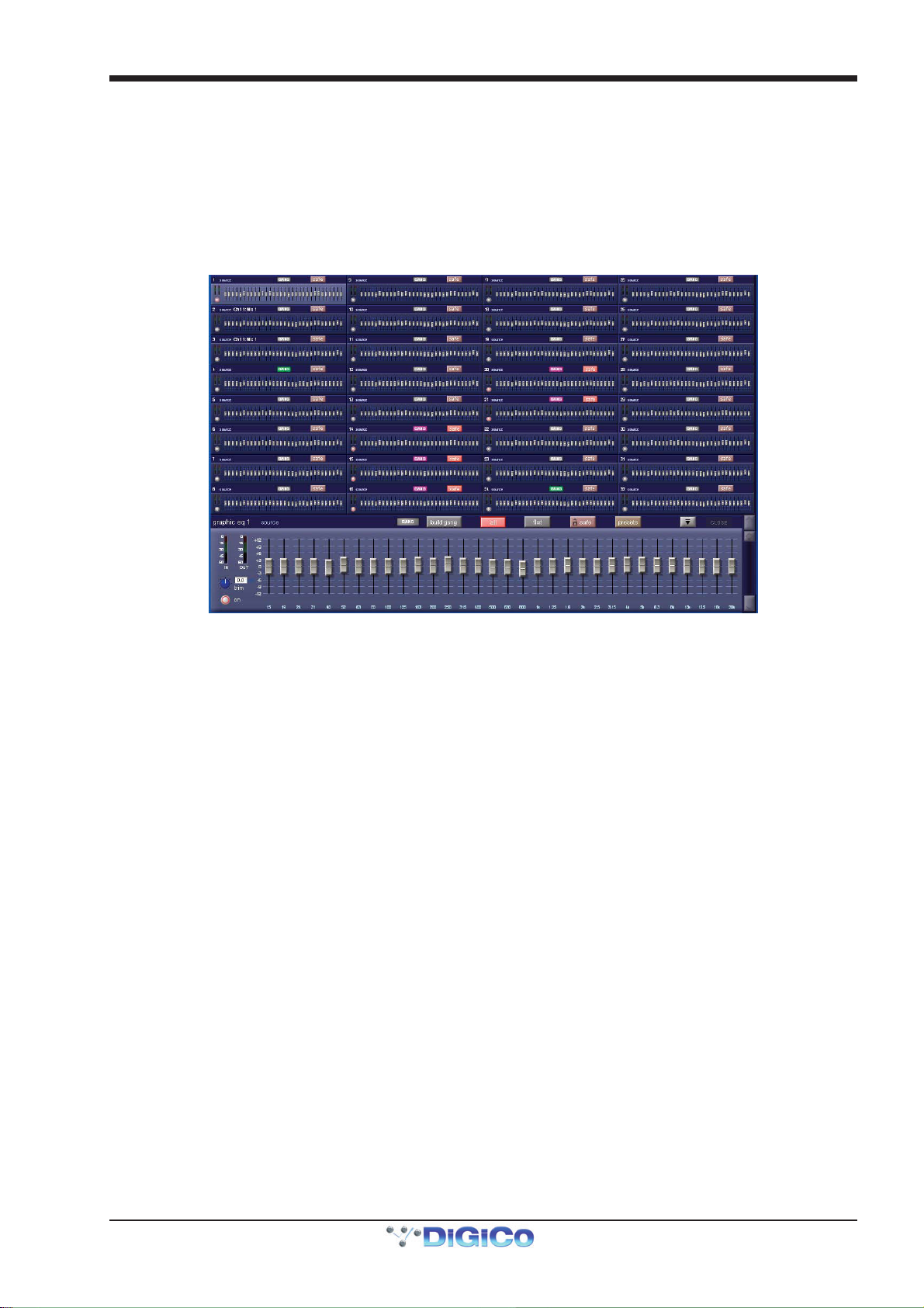
Chapter 2 - The Master Screen
2.8 Graphic EQs Menu
2.8.1 Graphic EQ Panel .................................................................
Touching the Graphic EQs menu opens a display of the console’s graphic EQs. This display allows all of the available 32-band
graphic EQ’s to be configured. Graphic EQ’s can be assigned to the inserts and outputs of all four channel types, and can also
feed the input of an input channel. Graphic EQ routing is done via the channel routing pages, and is not accessible from the master
Graphic EQs display.
The display consists of miniature representations of all available graphic EQ’s, one of which is also shown expanded in the bottom
of the display:
The settings on each graphic EQ are accessed via the expanded display, though some settings can also be adjusted in the
miniature display. Touch any of the graphic EQs to assign it to the expanded display. The EQ assigned to the expanded display
can also be scrolled using the scroll bar to the right of the expanded display. The EQ currently assigned to the expanded display is
indicated in the top left-hand corner of the expanded display, along with indication of the EQ’s source. The miniature display can
be opened and closed by pressing the expand button (a down-arrow when opened, and an up-arrow when closed) to the left of
the expanded EQ close button.
The left-hand side of the expanded display includes metering of the EQ’s IN and OUT signals, a ±18dB gain trim pot with value
indication to its right, and an on button which is ringed red to indicate that the EQ is on. Touch the trim pot to assign it to the
Touch-Turn encoder. To the right of these controls, the 32 EQ band faders are displayed. The label located beneath each fader
indicates the frequency of each band in Hertz, and the gain scale associated with each line on the display is indicated to the left
of the lowest band. Each band can also be altered within the miniature display.
2.8.2 Ganging Graphic EQs ...........................................................
The grey GANG and build gang buttons above the band faders are used for ganging together different graphic EQ’s. When EQs
are ganged, their band faders, on buttons and trim pots are locked together.
Note that ganging of faders is relative: EQs can have different shapes when they are ganged, and each EQ
will move by the same amount when a band is adjusted.
Note that if faders are moved within the miniature display, any other EQs ganged to them will also move.
When a set of Graphic EQs are inserted on a stereo or surround channel, those EQ units are automatically ganged together, and
are then automatically unganged when the insert route is removed.
Note that it is the Insert Return routing, not the Insert Send routing, which gangs EQ units.
To start building a gang manually, touch one of the graphic EQs to be included in the gang to assign it to the expanded display, and touch build gang. The button turns red to indicate that it is active. The GANG button to its left will also become coloured, indicating that it is included in the gang being built. To add further EQs to the gang, touch the relevant small Graphic EQ display on the other Graphic EQs to be included, and they will change colour to match the expanded EQ’s GANG button. To deselect any EQs from the gang, touch their GANG buttons again and they will return to grey. Touch the build gang button to complete the ganging process. EQ gang assignments can be adjusted by reselecting the build gang button.
Note - To temporarily isolate a Graphic EQ band from a gang, press and hold the mute button above the
band's fader and then make the adjustment to that fader - this move will only be made to that band on the
Graphic EQ that you are currently adjusting.
2-37
Page 72

Chapter 2 - The Master Screen
2.8.3 Graphic EQ ALL Button ........................................................
To adjust all graphic EQs at once, select the all button to the right of the build gang button. It turns red to indicate that it is active.
Adjusting any band in the expanded EQ will cause that band in all EQs to jump to that position.
Note that the all function is absolute: Once a band is altered, any variations on that band between the EQs is
eliminated.
Note also that the all function does not affect the normal operation of faders in the miniature display - they
still operate independently.
To return all 32 bands within one EQ to 0dB, touch the flat button to the right of the all button, and touch Yes in the confirmation
pop-up which appears.
Note that the flat function affects any EQs which are ganged to the expanded EQ.
Activating the safe button, to the right of the flat button, protects the graphic EQ settings from being overwritten by a snapshot
recall.
2.8.4 Graphic EQ Presets...............................................................
Touching the preset button, to the right of the safe button, opens the Graphic EQ Presets display in which current settings can
be saved and pre-created settings imported.
The positions of the trim pot, on button and all 32 faders are included in an EQ preset. To reset the channel to the default
settings, press default.
2-38
Page 73
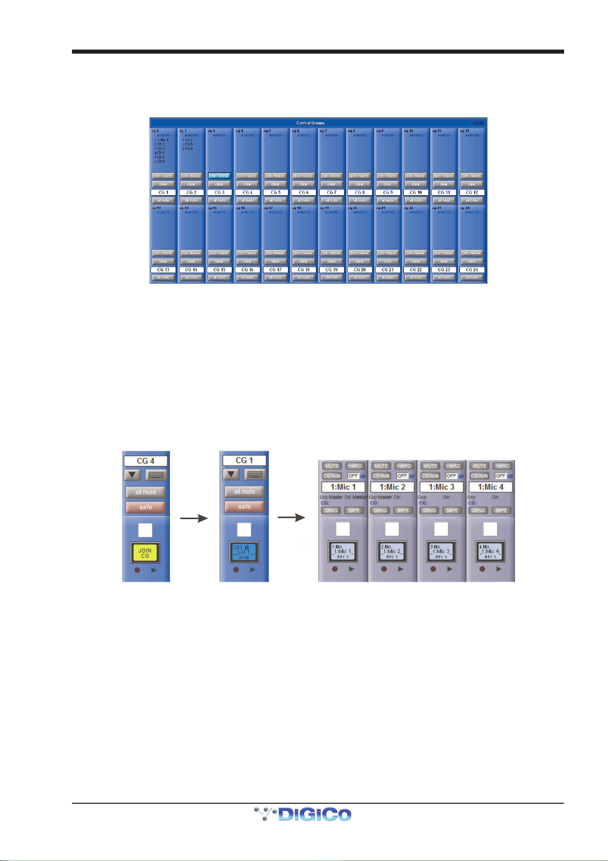
Chapter 2 - The Master Screen
2.9 Control Groups
2.9.1 The Master Control Groups Display.....................................
An overview of all the Control Groups within a session can be access via the Control Groups menu button in the master panel.
This display consists of basic versions of each Control Group channel strip, including the channel assignments lists and a number
of basic settings which can also be adjusted in the display: join/leave, clear and all mute. The Control Group naming controls
are also available within the display’s channel strips.
Any number of input channels and output channels can be connected to one or more of the Control Groups. They can then all be
operated from a single worksurface control. Changes to the Control Group fader, mute or solo or controls will affect all channels
connected to the group.
There are 2 methods to set up Control Groups:
1) Press the LCD Function button on the CG fader bank followed by the JOIN CG button;
Press the channel select button for the CG that you want to use;
Press the channel select buttons for each of the channels to be included in the CG;
Deselect the JOIN CG button:
Press LCD
Function Button
then JOIN CG
Select Control
Group to join
Press Channel LCD Buttons to assign members
2) Press the on screen JOIN/LEAVE button for the required CG channel; Press the channel select buttons for each of the channels that you want to make members of the CG; Release the JOIN/LEAVE button:
2-39
Page 74

Chapter 2 - The Master Screen
List of members
Press Join/Leave button on required CG channel Press Channel LCD buttons to assign members
A list of all the connected channels and their names is displayed above each Control Group display.
You can also clear all the channels from a Control Group by pressing Clear.
When a channel is a member of a Control Group, its own controls can still be adjusted independently of the other Group members.
Adjustments to fader levels are transmitted to the Group members as dB changes, so that a level increase of 2dB on the Group
fader will increase all the member levels by 2dB, irrespective of the relative levels of the individual channel faders.
Control Group Channel Strips
Note that Control Group channels function completely differently from Group channels: Group channels mix
together the audio from any channels routed to them, whereas Control Group channels simply move the
channel faders of any channels assigned to them, irrespective of any audio routing.
The number of control groups available is defined in the console Session Structure. Control Groups can be named using the
standard naming tools. The safe button, located at the bottom of the on-screen channel strip, can be used to protect the assignments and settings of the Control Group from being changed if a new Snapshot is fired.
All of the Control Groups to which an input or output channel belongs to are displayed immediately above the GANG and SAFE
buttons in the Channel strip panel.
Note that only the first two to three Control Group assignments within a channel can be displayed in the
channel strip.
All of the channels included in a Control Group are listed in the top half of the Control Group channel strip display.
To clear all of the channels currently assigned to a Control Group, touch the Control Group’s clear button, located below the join/
leave button, and press Yes in the warning display that appears.
2.9.2 Control Group Fader Modes ................................................
There are three modes in which the Control Group fader can interact with the faders of the channels assigned to it, and the button
below the clear button in the channel strip display toggles between them:
In moving fader mode, all assigned faders will move to replicate any Control Group fader movements.
2-40
Page 75

Chapter 2 - The Master Screen
Solo Trim
Solo Delay
Direct Out Level
N
pfl / afl solo mode
Floating Meter
Note that it is the level change associated with the fader movement which is replicated, not the physical
distance the fader is moved.
In vca style mode, moving the Control Group fader affects the output level of all assigned channels without moving their faders.
In mute only mode, the Control Group only controls the mute buttons of assigned channels, not the output level.
Note that in all three modes, moving the fader of a channel assigned to a group does not impact the output
levels of other channels within the group.
2.9.3 Control Group Mute Functions.............................................
The mute buttons within a Control Group interact in the same way, regardless of the current fader mode:
The mute button above the LCD display on a Control Group fader can be used to mute all of its assigned channels. Its function is duplicated by the all mute button below the channel’s scribble strip. When a channel is muted by its Control Group mute button, the channel's mute button lights in the normal way. The channel's CG mute button goes blue to indicate that the Control Group mute button (rather than the channel mute button) is responsible for the mute. When deactivated, the Control Group mute button returns all assigned channels to their mute state before the Control Group mute button was activated.
CG Mutes are treated as “in series” where a channel is a member of more than one group. All CG mutes must be off for a channel
to be unmuted; any CG muted always mutes all of its members.
If a channel is CG muted by single or multiple CGs, the worksurface channel mute button will override all CG mutes for that
channel. The channel will not however be removed from CG membership so if the relevant CG is muted again, the channel will
also be muted.
The auto-mute function, activated by touching the auto-mute button located above the Control Group name in the Channel Strip panel, automatically mutes any channel which is removed from that Control Group and unmutes any channel that joins the Control Group.
2.10 Solos Menu
2.10.1 The Solo Panel ...................................................................
Touching the Solos menu opens the Solo 1 and Solo 2 displays. These displays are used for configuring the console’s solo
busses. Solo buss 1 is configured in the left-hand display, and solo buss 2 in the right. Both displays function in exactly the same
way:
multi / single solo mode
Clear
Solo Level M ete r
Buss Format Switch
o solo source select
Insert routing
Direct Out routing
Headphones On / Off
activation
Direct Out Level
Fader Assignment
The SD7 Solo panel
Note that the in-channel solo functions are described in the Channel Types Chapter
At the top of each display is a black box containing the solo meter(s), three buttons, and an input trim pot. These controls are
duplicated on the console worksurface,
2-41
Page 76

Chapter 2 - The Master Screen
The first button selects which point in the channel feeds the buss, and toggles between PFL and AFL, as indicated by the pfl or
afl labelling above the button turning green. The button is also ringed green on the worksurface when afl is selected.
The second button toggles the two solo button modes: multi in which multiple channels can feed the solo buss at once, or single in which only one channel can feed the buss. In single mode, when a channel is feeding the solo buss, pressing the solo button on a different channel will cause the originally selected channel to be deselected from the solo buss. The solo button mode is indicated by the multi or single labelling above the button turning red. The button is also ringed red on the worksurface when single is selected.
All feeds to the solo buss can also be cleared by pressing the clear button. When there is a feed to that solo buss somewhere on
the console, the button is ringed blue on the worksurface.
The level of the solo buss can be adjusted using the trim encoder on the worksurface. The on-screen trim pot is always assigned to this worksurface encoder, as indicated by the presence of green ring around it. The signal can be trimmed by ±18dB,
and the trim value is indicated to the right of the on-screen trim pot.
In the centre of the Solo 1 or Solo 2 display, there is an auto solo area which lists all the channels which are selected for the
auto solo function. This function automatically routes selected channels to that solo bus whenever another channel is soloed,
and the selected channels can be scrolled if necessary using the scroll bar on the right of the list. The auto solo channels are
selected in the Channel Setup display. This auto solo function is enabled and disabled by touching the left-hand blue button
below the auto solo list. The button label displays whether the auto solo function is enabled or disabled. The channels in the
auto solo list can all be removed by touching the clear all button below the auto solo list.
Tip: If you are using effects returns, selecting auto solo will allow soloed tracks to be auditioned with their
effects returns - this function only works in Multi-Solo mode.
The solo buss signal can be delayed using the delay pot to the right of the auto solo area. Switch the delay on using the on button below the pot. Touch the pot to assign it to the Touch-Turn encoder. The delay value has a range of 0 to 2.7 seconds and is displayed above and to the right of the delay pot.
The mono, stereo and surround buttons to the left of the auto solo area select the size of the solo buss. Each button is red
when selected and grey when not selected. The selected format is also indicated by the number of meters displayed in the topleft corner of each display.
2.10.2 The No Solo Setup Display ................................................
Below the mono, stereo and surround buttons, is a button marked no solo. This button defines what signal (if any) is present
on the buss when no channel solo is active. By default, there is no signal feeding the buss when no channel solo is active.
Pressing this button opens the No Solo Setup display:
At the top of the display, there is a text box which can be used for renaming the solo buss. Touch the box or the keyboard symbol
to its right, type the new name on the on-screen or external keyboard and press OK. The Channel Name display containing
commonly used words for quick insertion can be accessed for buss naming by touching the down arrow immediately to the right
of the text box. The solo buss name will then appear at the top of its master solo display, and in any solo-assigned master faders
(See below for details).
Below the naming area, there are two columns of buttons used for selecting the audio source for the no solo function from
among the group and aux channels. The left-hand column contains two pairs of buttons: the groups buttons (mono or stereo)
and the auxes buttons (mono or stereo). Touching one of these buttons causes it to lighten to indicate that it is selected, and
results in a list of those channels appearing in the right-hand column. A scroll bar appears in the right of the display if the channel
list is too long for the window.
Touching one of these signal buttons assigns it to the no solo function, as indicated by the lightening of the signal’s button and by the labelling immediately beneath the no solo button displaying the signal name. If a stereo signal is selected here, only the lefthand signal is displayed beneath the button. Signals can be deselected by touching them again. When no signal is selected for the no solo function, the labelling beneath the button displays none.
2-42
Page 77

Chapter 2 - The Master Screen
To close the No Solo Setup display, press the CLOSE button in the top right-hand corner.
The area below the auto solo area concerns the solo buss outputs. In the centre of the output area, there is an output level pot.
Touch the pot to assign it to the Touch-Turn encoder. The buss output level trim ranges from OFF to +10dB, as indicated to the
right of the pot.
2.10.3 Assigning Solo Busses to Faders.......................................
The solo buss output level can also be assigned to the master fader(s) by pressing the assign level to master button(s) to the
right of the level pot. Each button is highlighted in gold when it is selected. When a solo buss is assigned to a master fader, the
master fader LCD button displays green, and the button lightens to indicate when any channels are assigned to the solo buss.
The top half of the LCD buttons displays the solo buss number along with any name given to it in the No Solo Setup display.
When the fader is moved, the bottom half of the LCD button displays the fader level.
When a solo buss is assigned to a master fader, the fader’s LCD button becomes a solo clear button, as indicated by CLEAR
being displayed in the bottom half of the button when the fader is stationary.
Solo Busses can also be assign to channel faders by using the LCD Function>assign faders and selecting the solo channels
from the channel list.
2.10.4 Solo Outputs Routing..........................................................
Each solo buss includes an insert send and return, and a direct output, both of which are routed in the Solo Outputs display.
This display is accessed by touching the insert button below the no solo button, or the direct outs button in the top left of the
solo buss output area.
This insert point only applies to the Solo buss Direct Output, not to the headphone signal.
At the top of the Solo Outputs display, the buss naming function described above is duplicated. Towards the bottom of the
display, there are two buttons marked output and insert A. Selecting one of these buttons assigns that send (or send and
return) to the signal routing area above it: When the insert is assigned, the ins A send routing button appears in the left-hand
column, and the ins A return routing button in the right-hand column; When the output is assigned, the outputs routing button
appears in the left-hand column and the right-hand column is left blank. Pressing any of these routing buttons opens a routing
display. Insert and output routing can then be routed as described in the Getting Started section.
An extra button labelled send+return is included above the ports list in the Insert Send Route display button. When this button
is activated, the send and return routing is linked for all signals within the INTERNAL port: If the Graphic 1 input is assigned to the
insert send, the Graphic 1 output is automatically assigned to that insert return. Similarly, if it is the return which is manually
assigned, the send automatically copies that send assignment. The send+return button is grey when inactive and brown when
active.
Once the insert send and return signals have been selected, level trim pots appear in the bottom half of the Solo Outputs display.
To the left of both pots there is a meter (or pair of meters, in the case of stereo channels) displaying the send or return level, and
to the right of both pots there is a numeric display of the level trim in dB. Below the send level trim there is an on button which
switches the send on and off. Below the return level trim there is a reverse phase button which inverts the phase of the returning
signal. Both of these buttons become ringed in red to indicate that they are on.
Once any insert or direct out has been routed, the route is displayed below the button in the Solo 1 or Solo 2 display.
2.10.5 Headphone Outputs ............................................................
Touching the headphone button in the bottom left-hand corner of the display sends the solo buss signal to the headphone socket(s), located under the arm rest. The button turns blue to indicate that it is active.
The headphone output(s) receive both solo buss signals, and the headphones will be silent when neither buss is routed to them,
unless a no solo signal has been assigned.
The headphone level is controlled by the output level pot in the output area, and also by the headphone level encoder located on
the surface. The headphone signal can be muted by pressing the mute button next to the worksurface headphone level encoder,
and the button is ringed red to indicate that the headphone send is muted.
2.10.6 Solo Meters .........................................................................
Solo meters can be displayed on the Master or Overview screen by pressing the floating meters button below the solo delay area in either side of the Solo panel.
Floating meters are described in the Channel List section of this chapter.
2.10.7 Solo As an Input Source ....................................................
Function only available on a Default Session created in SD V680+
Both Solo 1 and Solo 2 are available as input sources for all channel types. A warning confirmation will appear on screen before
the route is made.
WARNING: Soloing a channel that has a solo buss as its source will result in a feedback
loop being created and dangerously high audio levels at any output routed from the solo
buss or channel
2-43
Page 78

Chapter 2 - The Master Screen
Press the Selec t button to choose which
at
Once synchronised, session detail
2.11 Network and Mirroring
2.11.1 Network Configuration .......................................................
Any two SD Series consoles of the same type can be mirrored together to provide a fully redundant audio system. The SD7
console is fitted with two separate engines, and as such, offers built in redundancy.
In order to take advantage of this redundancy, you need to verify the console networking is working, and synchronise your
session between the two consoles/engines.
Before the consoles/engines can be mirrored, you should ensure that a standard crossover network (Ethernet) cable is connected between the two consoles/engines. Without this connection, the two consoles/engines will not “talk” to each other.
To open the Network window, touch the Network button at the top of the Master Screen. The following window will open…
for both Engines w ill match
Optocore ID
device to send to or receive a session from
When highlighted in orange
the Audio Master button indicates th
this audio engine is curr ently active
Press here to send a session
to the selected device
Press here to recei v e a sess ion
from the select ed device
Press here to Mirror To or From
the selected device
2.11.2 Mirroring for the first time ..................................................
If the consoles are connected together, but do not see each other, then you may need to enable Networking.
There is an option in the OPTIONS/SESSION tab to ENABLE CONSOLE NETWORK (YES/NO). This must be set to YES on both Engines. After doing this, shutdown and restart both consoles/engines and when the sessions are loaded go to the NETWORK window and you should see yellow OK lights against A & B. This indicates that the network has connected the two consoles/ engines but they are not yet mirrored.
In order to mirror the two consoles/engines, they need to be running the same session. The way to achieve this is to load the
session into the A console/engine, then transfer it to the B console/engine using this Network window.
1. Ensure you are switched to the A console/engine.
2. Load your session into console/engine A
3. Open the Network Window
4. Press the Select button for console/engine B and then press the Send Session To Selected button.
This will copy your current console/engine A session and load it into the B console/engine. Once this is done, the console/engine
B detail section will change to reflect the new loaded session.
You can now press the Mirror button. The Mirror buttons will turn green, and the console is now mirrored. Audio Mastership can
be switched between console/engine A and console/engine B using the Audio Master button and, assuming that the racks are
correctly connected, you will not hear the switch of between the two engines.
There is also an option to Receive Session From Selected which allows a session file to be brought into one engine from
another.
When the Mirror From Selected or Mirror To Selected buttons are pressed, the current worksurface mix settings like fader positions are transferred from one device to another. If you have sent or received a session and then made some simple changes, the additional adjustments are normally transferred when you activate the Mirror mode. If there is a significant difference between the two devices' settings at that point, you will be prompted to resync the session.
On an SD7, the ENGINE A/B switch at the top of the centre worksurface will switch the entire worksurface from one engine’s
control computer to another. It will not (by default) switch the audio processing from one engine to the other. This is achieved by
pressing the relevant Audio Master button in the network window on either engine. When the button is orange, the engine is
active.
There is an option in OPTIONS/SURFACE tab that enables the switching of both control computer and audio mastership at the
same time with the worksurface ENGINE A/B switch. When first configuring the system, we do not recommend running in this
mode
2-44
Page 79

Chapter 2 - The Master Screen
2.11.3 Mirroring Mode ...................................................................
This option determines how the console will behave when Mirrored via a network to another console, engine or Offline PC.
This option is saved for console not in the individual session.
There are 4 modes of operation.
Full Mirror - all functions mirrored from one device to the other - this mode should be used on both engines in an SD7. Expander - intended for use with an SD7 console and an EX007 Expander unit. The second device mirrors most functions from
the first device but significantly, allows different banks to be selected on the different devices. Remote - intended for use with a PC being used as a Remote Control for a console. Allows different banks to be selected and
different setup options on each device. One Way - this mode is intended for remote monitoring of what another device is doing. If a device is in One Way Mirror mode, it
can "see" what the other mirrored device is doing but cannot control the other device. This mode is only likely to be used in
exceptional circumstances.
When mirroring 2 single engine consoles, the correct mirroring mode will depend on the operational requirements of the system.
2.11.4 Mirroring with a laptop PC.................................................
An SD Series console can also be connected to a laptop PC running the Windows operating system in similar way to achieve
remote control of the console.
When running SD software on a PC, the software will appear in a number of "floating" windows, each of which represent a
console section. A screen touch on the console is simulated by a right click with the PC mouse. To switch between console
sections use the small toolbar buttons that also appear on the screen marked Master\Left\Right.
The DiGiCo website has downloads available for all current versions of "Offline" software.
The SD software on the PC is identical in operation to the console software and the USB key that is provided with the console will
contain the SD offline software installation package.
Run the Installer from the USB Key. It will create folders in the root directory of your PC's C:\ drive and place a shortcut to for the
Offline Software on the desktop.
IMPORTANT NOTE - When mirroring a console to a PC you are required to set a static IP address on your PC
which is in the same subnet as the console itself. The console's subnet mask is 255.255.0.0 255.255.255.0 (SD7
only) and its IP address can be seen next to its entry in the Network panel - in the picture above it is
192.168.2.84 for Engine A.
The IP address of the PC must start with 192.168.2.xxx. and must be different to that of the console.
The setup of network addresses on a PC may differ from one operating system to another so if you are in
doubt, please consult the documentation for your PC's operating system before proceeding.
As an example, on Windows XP, the IP address and subnet mask can be changed by:
1) Opening the Control Panel>Network Connections.
2) Right clicking on the Local Area Connection and selecting Properties.
3) Double Click on Internet Protocol (TCP/IP) from the list to show its Properties.
4) Set the radio button to Use the following IP address
5) Type the IP Address and Subnet Mask as detailed above
6) Confirm the changes and restart the computer
2-45
Page 80
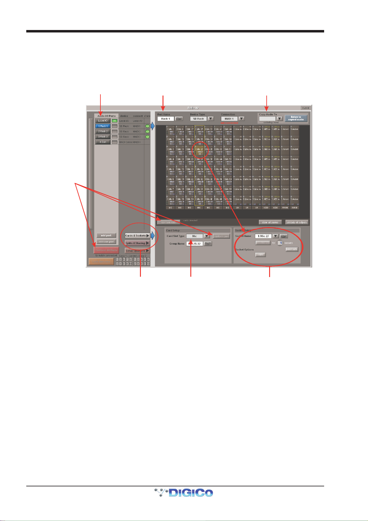
Chapter 2 - The Master Screen
Edit the Port Name here.
and edit Group Name
A
i
o
Copy Rack Audio to MADI
2.13 Setup Menu
APPENDIX A of this manual contains further details about Optocore connected systems
2.13.1 Audio I/O..............................................................................
The Audio I/O display is used to configure the physical I/O connected to the SD Console, including identifying and naming the
sockets of the option cards installed in racks, and the setting of pads and phantom power.
uto Conforming for all ports,
ndividual racks,
r individual cards
Select the port to be configured
Eg. Stage Rack, Local Rack etc...
Select the contents of the bottom-right
corner of the Audio IO window
Select Card Type manually or
using Auto-Conform function,
Selected Socket Properties
Edit Name and Socket options.
2.13.2 Port Selection .....................................................................
The ports buttons in the top left-hand corner of the display select which port is being configured in the rest of the display. Each
port relates to a set of physical audio connections:
Local I/O The I/O installed in the rear of the console
Rack A remote I/O rack connected via MADI or Optocore
Con A separate console connected using MADI or Optocore,
Once a port has been selected, the connections contained within it are displayed in the Sockets graphic which makes up the most
of the rest of the Audio IO display.
The box to the right of each port selection button displays the current state of the connection:
New optocore ports can be added to the ports selection area by pressing the add port button, below the Connection box.
User-created ports can also be deleted by pressing the remove port button, below the add port button.
Copying Audio and Listening to Copied Audio (MADI Recorder Setup)
Any incoming MADI or Optocore connected rack stream can be copied to any other MADI Output by selecting the incoming Port in the Ports list and using the Copy Audio To drop down menu. For example, if you want to copy Rack 1's Audio Inputs to a MADI equipped recorder connected on Port 2, select Port 1 in the ports list and then select MADI 2 from the Copy Audio To drop down menu.
The console will send the 56 or 64 channel MADI stream to MADI Output 2 and it can be recorded as necessary.
In addition, by connecting the recorder's MADI Output to the console's MADI 2 Input, the playback can be monitored in the same
channels as the original source material. Just press the Listen To Copied Audio button to monitor playback and press it again to
return to monitoring the live sources from the rack.
When Listen to Copied Audio is active, "Listening to Copied Audio" is displayed in the session status panel of the master screen.
More complex inter port routing is possible using the Copy Audio Panel. Please see the COPY AUDIO section of this manual.
2-46
Page 81

Chapter 2 - The Master Screen
2.13.3 Port Hardware Configuration.............................................
The port is named automatically according to its connection type, as displayed to the right of the ports selection area. However,
the name can be edited by touching the Port Name box or the keyboard symbol to its right, typing the new name into the QWERTY
keyboard which appears, and pressing OK. The type of device connected to the port can be altered by touching the down arrow
next to the Device Type box, located next to the Port Name box, and selecting the appropriate device from the drop-down list
that appears. The physical port being used to connect the device can be altered by touching the down arrow next to the Con-
nection box, to the right of the Device Type box, and selecting the appropriate connection port from the drop-down list that
appears. The current status of the connection is displayed below the Connection box as either connected (in green) or not
connected (in red).
Note that the configuration of the Local I/O port is fixed, so no hardware changes are possible. You can,
however, change the Port Name, the Group Names (relating to name of each physical card) and the Socket
Names (the name of each physical connector on a card).
2.13.4 Port Control .........................................................................
Normally, the input gain, phantom power and pad of each DiGiCo Rack input is controlled remotely from the SD Console. However,
in multi-console systems where Racks are shared between two DiGiCo consoles with MADI Connections, only one of the consoles can remotely control these rack settings. With Optocore connections any console can have control. Therefore, the level of
control given to each console must be defined. Control options are displayed in the bottom-right area of the Audio I/O panel when
the Splits & Sharing button towards the base of the panel is pressed:
There are three levels of control:
isolate: The SD Console will not exchange any control data with the rack. This means that the console will neither be able to
adjust rack settings, nor adjust its own settings according to returning control data.
receive only: The SD Console will receive the rack’s existing settings but not send control data back. This means that the
console will not be able to adjust rack settings, but will be able to adjust its own settings according to returning control data.
full control: The SD Console will receive the rack’s existing settings and will send control data back. This means that the console
will be able to adjust the rack’s settings and receive tallies back from the rack.
When the Rack port is selected in the main panel, its control can be defined as shared by pressing the Shared button. Individual racks can also be controlled using the isolate, receive only and full control buttons beneath the Shared button - these buttons will only affect the selected port.
2.13.5 The Socket Display .............................................................
When a port has been selected from the ports list on the left, the individual connections within that port are displayed in the
Sockets graphic, which makes up most of the rest of the Audio IO display. For Rack or Console ports, each column in the graphic
represents an IO card, and the type of IO card is displayed at the bottom of each column. For the Local I/O port, each row
represents a type of I/O socket.
Each individual socket displays the following information: the current socket name is across the middle, and the socket number
within the card is in the top left-hand corner.
For analogue input sockets, the current gain is at the bottom, and the top right-hand corner displays a red 48 symbol if the socket’s
phantom power is switched on.
For analogue rack output sockets, there is a -10 symbol in the top right-hand corner which is yellow to indicate that the 10dB pad
is switched in, and white to indicate that no pad is present.
For digital inputs the status of Sample Rate Conversion On/Off is displayed.
Touching a socket within the graphic assigns that socket and its card to the area below the graphic for configuration, as de-
scribed below.
The number in the top left corner of an output socket will change colour if the socket is being used by the Copy Audio Function.
2.13.6 Socket Conforming .............................................................
In order to use the rack, the on-screen contents of the rack must match the cards physically installed in the connected rack. There
are two ways of achieving this:
Manual Conforming
Select each card (column) and manually select the appropriate card in the Card/Slot Type drop down menu in the lower section
of the window. Once the correct card type is selected, the card type name at the bottom the selected card will turn green,
2-47
Page 82
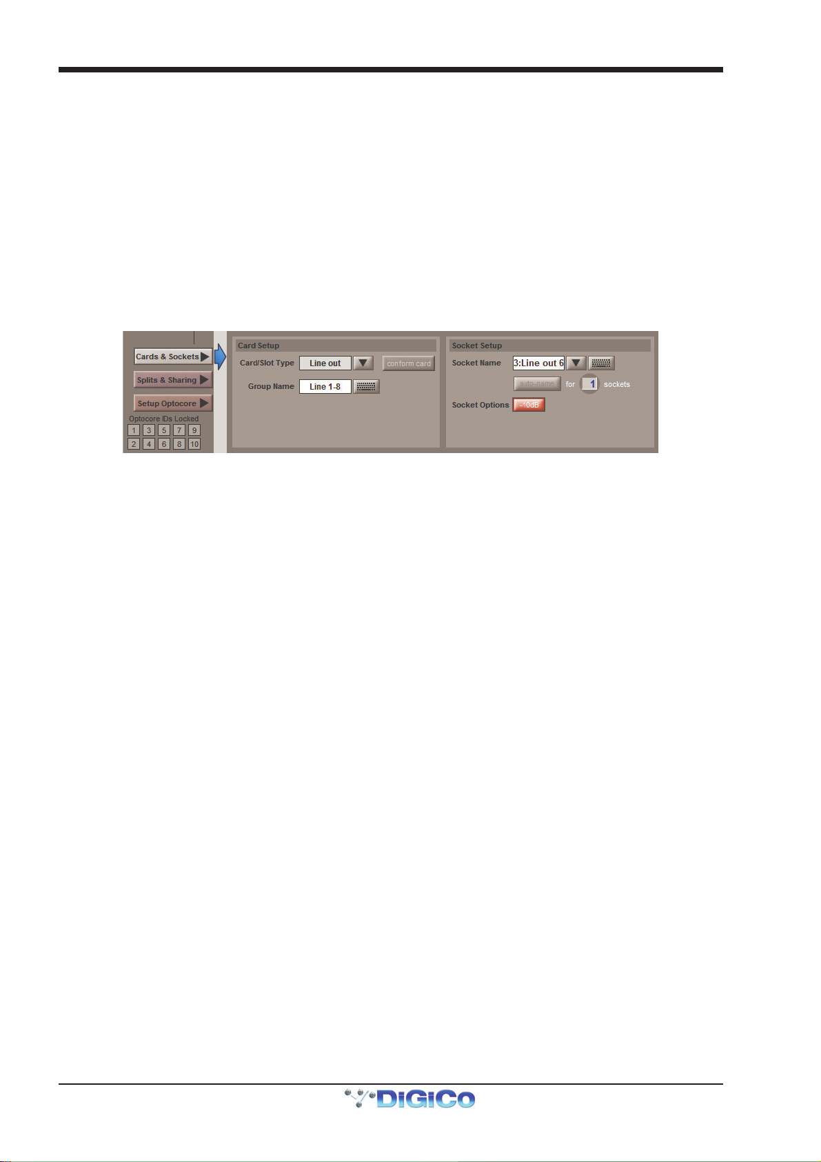
Chapter 2 - The Master Screen
indicating the card type matches the card installed in the rack. If there is a mismatch, the card type name will be red, and the error
should be corrected by selecting the correct card type.
Automatic Conforming
The audio I/O can be automatically conformed for the whole console (using the Conform All Ports button in the bottom left of the
panel) or the currently selected rack (using the conform rack button below the socket display). Pressing these buttons will
correctly select the correct card for each slot. Once complete, all of the card labels beneath each slot should turn green.
It is also possible to auto-conform on a card-by-card basis: With a single card selected (by touching any of the sockets on that
card), press the Cards & Sockets button towards the base of the screen, followed by the conform card button which
appears in the area to its right.
2.13.7 Group and Socket Names ..................................................
Cards and sockets are named automatically, according to the Device Type, Card/Slot Type and their position within the port. To edit these names, press the Cards & Sockets button towards the base of the Audio I/O panel to bring up the Card Setup and Socket Setup displays to its right:
Touch either the Group Name or the Socket Name box (or the keyboard symbols to their right), type the new name into the QWERTY keyboard which appears and press OK. Touching the down arrow in between the Socket Name box and keyboard symbol opens up the Channel Name display which enables commonly used words to be inserted quickly without the use of the keyboard.
A range of sockets can be named with the same label and an incrementing number by using the auto-name function below the Socket Name box: To define how many sockets will be auto-named, touch the numeric display, turn the Touch-Turn encoder to the right of the screen until the numeric display below the keyboard symbol displays the correct number. Alternatively, touch the numeric display, type in the number of sockets to auto-name into the keypad that appears, and press OK. Once the number of sockets has been defined, the auto-name button becomes active. Pressing it will cause the name of the assigned socket to be replicated for all the sockets selected for auto-naming. If the assigned socket’s name does not end in a number, a ‘1’ will be added to it and incremented for the remaining sockets. If the assigned socket’s name already ends in a number, that number will be incremented for the remaining sockets.
2.13.8 Socket Options ....................................................................
Depending on the socket type, further Socket Options are displayed below the Socket Name area.
2-48
Page 83
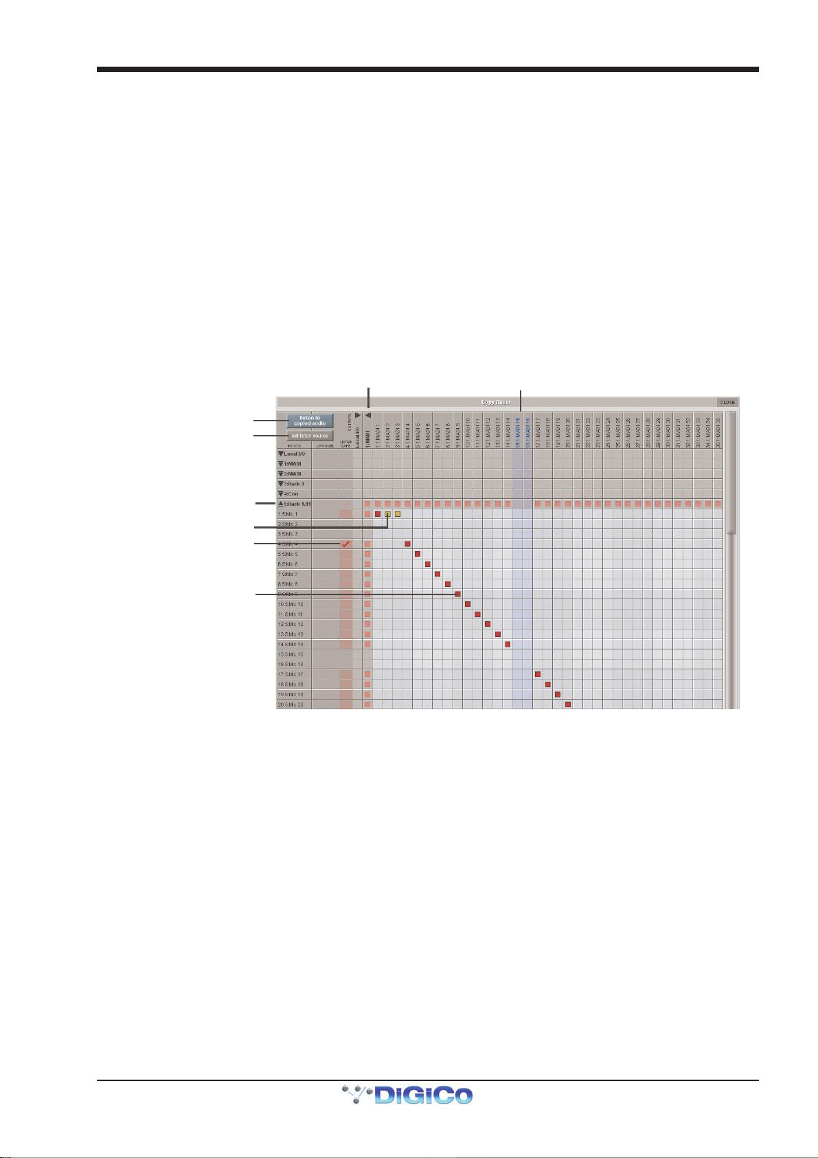
Chapter 2 - The Master Screen
Text/Shading in blue
O
b
2.13.9 Copy Audio ..........................................................................
The Copy Audio Matrix, located in the Setup Menu, has been designed to serve 2 purposes:-
1. To provide a flexible system for routing input sources from multiple racks to a recording system.
2. To route inputs from one rack to the outputs of another rack without using up console processing resources.
Any input socket connected to a console port can be copied multiple times to any output port socket. One of these “copies” can
be nominated as your “Listen Source” for when Listen to Copied Audio is activated.
It is also possible to place a copied input socket in “Listen Safe” so that when Listen to Copy Audio is activated, the original
source will be heard rather than the copy source.
Copy Audio settings are not snapshottable and remain constant throughout a session unless they are manually changed by the
user.
Setting up the system
In Audio IO, conform all your ports, make any required Optocore output allocations and map your system.
indicates output socket
unavailable
Listen To Copied Audio
Set Listen Source
Expanded view of rack inputs
range square indicates copi ed
ut not set as the Listen Source
Red tick ind i ca te s so ck et
is in Listen Safe Mode
Red square indicates copied
and set as the Listen Source
Expanded view of rack outp uts
Open the Master Screen / Setup / Copy Audio panel and you will see the collapsed matrix with input ports listed down the left side
and output ports across the top.
The input port list on the left shows all available input ports that have been configured in Audio IO including Local IO, MADI and
Optocore connections. Touching on any of these ports will expand the list to show the individual sockets. If a socket has been
routed into an input channel, the channel name will be shown in the “Channel” column.
The output port list across the top shows all available output ports that have been configured in Audio IO. When expanded, any
output socket that is already in use or is not allocated to your console is shown in blue and its column highlighted. Existing routes
from channels/busses cannot be overwritten in Copy Audio.
If a port is expanded, touching anywhere in the sockets list will collapse that port.
To make a copy route, expand an input port and output port and touch/drag on the grid. You will see the selected cells turn red. This first copy, by default, is defined as your Listen Source. Any subsequent copies of the same input socket are shown as orange cells. You may copy an input socket to as many locations as you wish but only one can be defined as your listen source. You can change the defined Listen Source by first pressing the “Set Listen Source” button in the top left corner of the panel and then touching on cell in the matrix. This cell will turn red and any previously selected listen source cell will turn orange.
If you have used the “Copy Audio To” function in the Audio IO Panel and the open the relevant ports in the Copy Audio panel,
you will see a diagonal line of Red cells between the source port and the destination port.
If an output socket is being used as a copy destination, this will be indicated in the Audio IO page by card socket number showing
red (for a Listen Source) or orange (for a copy). You will also see a red/orange square next to any sockets in use in any channel/
buss output routing panel. Please note the copy routes CAN be overwritten by output routes.
2-49
Page 84
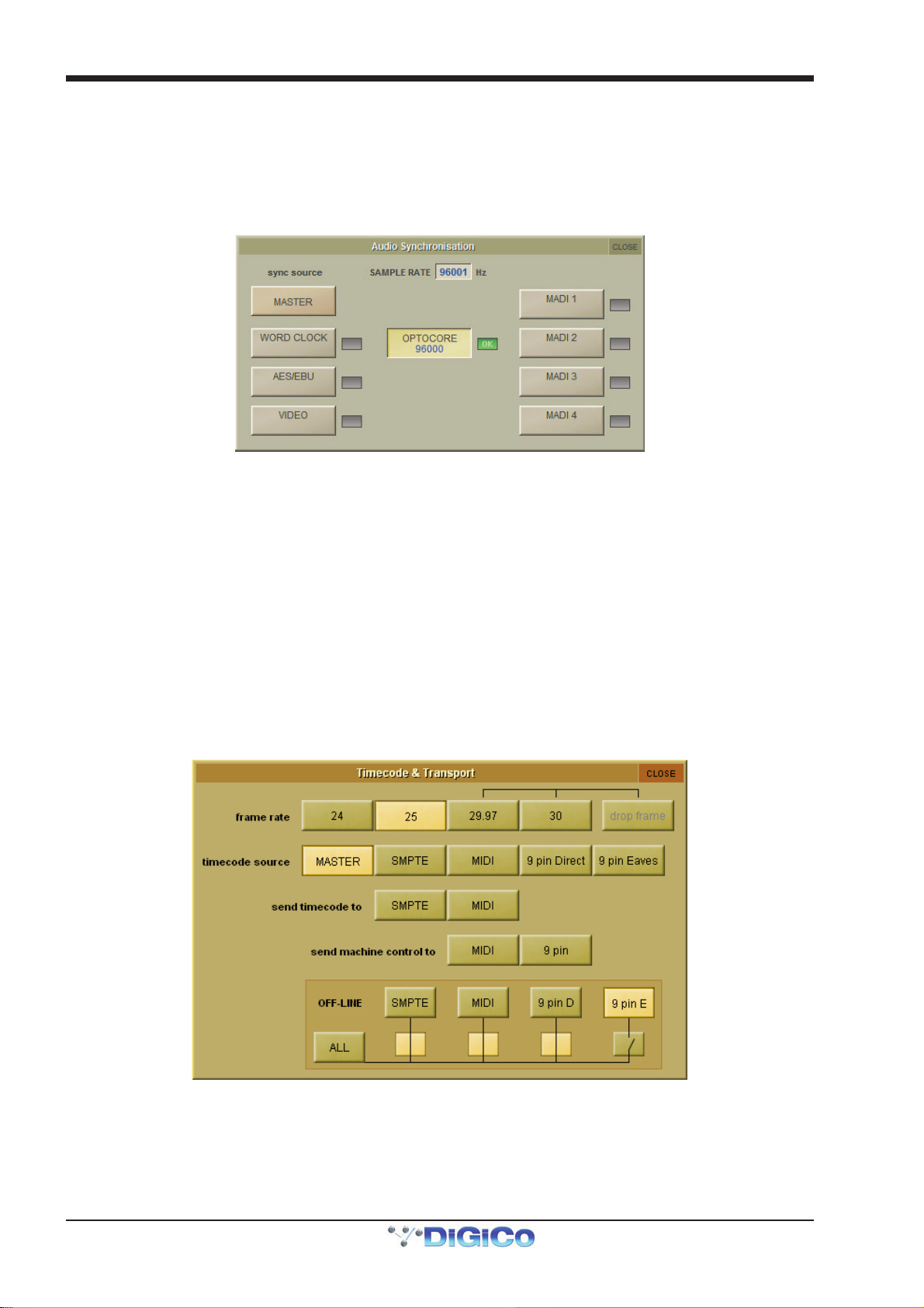
Chapter 2 - The Master Screen
Listen Safe
Listen safe is designed to allow the user to “Safe” a channel from the “Listen to Copied Audio” selection. This can be activated
from the Copy Audio Panel, the Channel List (when in Edit mode) or any Input Channel Setup Panel. When active, the Input
Channel Name box will turn red. As the Listen safe is associated with the input socket, Main and Alt inputs have independent
listen safes.
2.13.10 Audio Sync ........................................................................
Selecting Audio Sync from the Setup menu opens the Audio Sync display. This is where the clock source is selected:
The SD7 Audio Sync Panel
An SD Console will operate at Sample Rates of either 48000Hz (48kHz) or 96000Hz (96kHz), as configured in the Session
Structure panel.
By default, it is set to clock internally (Master) but the standard Audio Sync method is Optocore when the entire system uses the
device with the lowest Optocore ID (usually ID1) as its sync source.
This setting is saved within the session file so if any console(s) are connected to racks with optical fibre then all console engines
should be set to Optocore as their sync source.
There are also times when the console needs to be clocked externally. The Audio Sync panel allows you to control external
synchronisation.
The console will clock from the following sources : Word Clock, AES/EBU, Video Reference (SD5, SD7), MADI & Optocore
In this situation one Optocore device should be set to clock to the external source and all other Optocore devices should be set to
sync to Optocore.
Note : When a valid clock is detected on an external sync input, the corresponding Green OK box will light, even if
that input is not selected as the clock source for the console.
2.13.11 Timecode & Transport ......................................................
When the SD console is used in typical live sound applications there will be no time related control systems
(timecode) or motion control (tape transport) connected. Synchronisation and machine control does not need to
be considered.
This panel can be accessed by touching the Setup button on the Master screen and then touching the Transport & Timecode
button.
2-50
Page 85
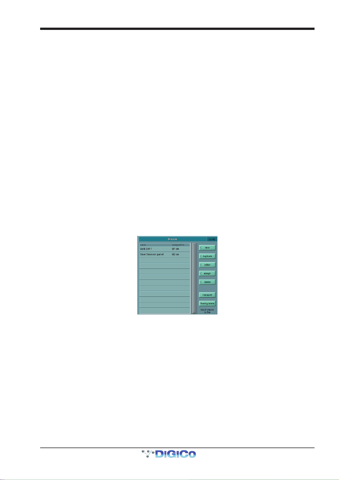
Chapter 2 - The Master Screen
Frame Rate
This must be set up for the frame rate used by your other equipment. You can select from four different basic frame rates, with a
drop-frame option available for 29.97 and 30fps.
Timecode Source
You can choose the Console option to make the console generate the master timecode for the setup, or you can choose to make the console "chase" timecode which arrives at one of the external sockets - SMPTE (LTC) (SD7 Only), MIDI (MTC), or 9-pin. These external sockets are located on the console rear panel.
The 9-pin Eavesdrop option requires a special 9-pin cable . The option is provided for installations where the 9-pin connection runs between two other pieces of equipment (for example, a video machine and DAW), but the console is required to chase this timecode. 9-pin does not normally allow more than a single direct connection between two machines, but using the Eavesdrop cable, you can make the console "listen" to the timecode passing between two other machines, and to sync to and display this timecode on the worksurface.
Note - if you are using 9-Pin Eavesdrop mode, you cannot use any of the options for direct 9-pin connection.
Timecode Output Enable
Whether the console is operating as timecode master or deriving its timecode from another device, you can choose to route a
timecode signal out from the MIDI (MTC) and/or SMPTE (LTC) sockets. If timecode is being received from another device it is
regenerated before being routed to the output.
Machine Control Enable
The console can only send Control signals if you have enabled a Machine Control output. This can be MIDI Machine Control (MMC)
and/or 9-pin Disk or Tape. Note that you cannot output 9-pin control if you are using the Eavesdrop option to read timecode.
MIDI Machine Control has limited transport features, supporting only the Play, Record, FF, Rewind, Stop and Locate functions. 9-pin control supports Shuttle and Jog functions.
Off-line Buttons
The configuration panel allows you to temporarily disable all timecode and transport control to any combination of outputs. The
ALL button disables all timecode and machine control output - this is especially useful to prevent external machines trying to
chase the console timecode.
2.13.12 Macros ...............................................................................
Selecting Macros from the Setup menu opens the Macros display. This display is also opened by pressing the assign button in the macros area of the worksurface.
This is where macro commands can be assigned to the smart keys or Macro buttons in the macros area of the console surface, as well as to the function (F) buttons on the external keyboard and to the console’s GPIs. Macros can also be fired directly from this list by touching the macro when none of the right-hand buttons is active.
The macros area has capacity for either 8 or 40 macros, arranged in one bank of eight, four banks of 10 or eight banks of five
depending on the console. If the console has bank buttons, pressing any of the bank buttons across the top of the macros area
assigns the smart keys below them to that bank. The bank currently assigned to the smart keys is indicated by its button being
ringed green.
The Macros display includes a list of all the macro commands which have been created, along with the button to which they
have been assigned, if this has been selected. The list is scrollable using the scroll bar to the right of the list.
Note that this list therefore includes macros which have been created but have no trigger.
Pressing the Transport Button will automatically assign the console transport controls to the macro buttons overwriting any
existing assignments.
On SD8,9,11, pressing the floating labels button opens a panel on the console's master screen that shows the worksurface macro buttons and their name label if macros have been assigned to them. Touching either the button or the label will fire the macro.
To create a new macro, touch the new button, in the top right-hand corner of the display. To create a macro based one that
already exists, touch the duplicate button below the new button, followed by the macro you wish to duplicate. When either
2-51
Page 86
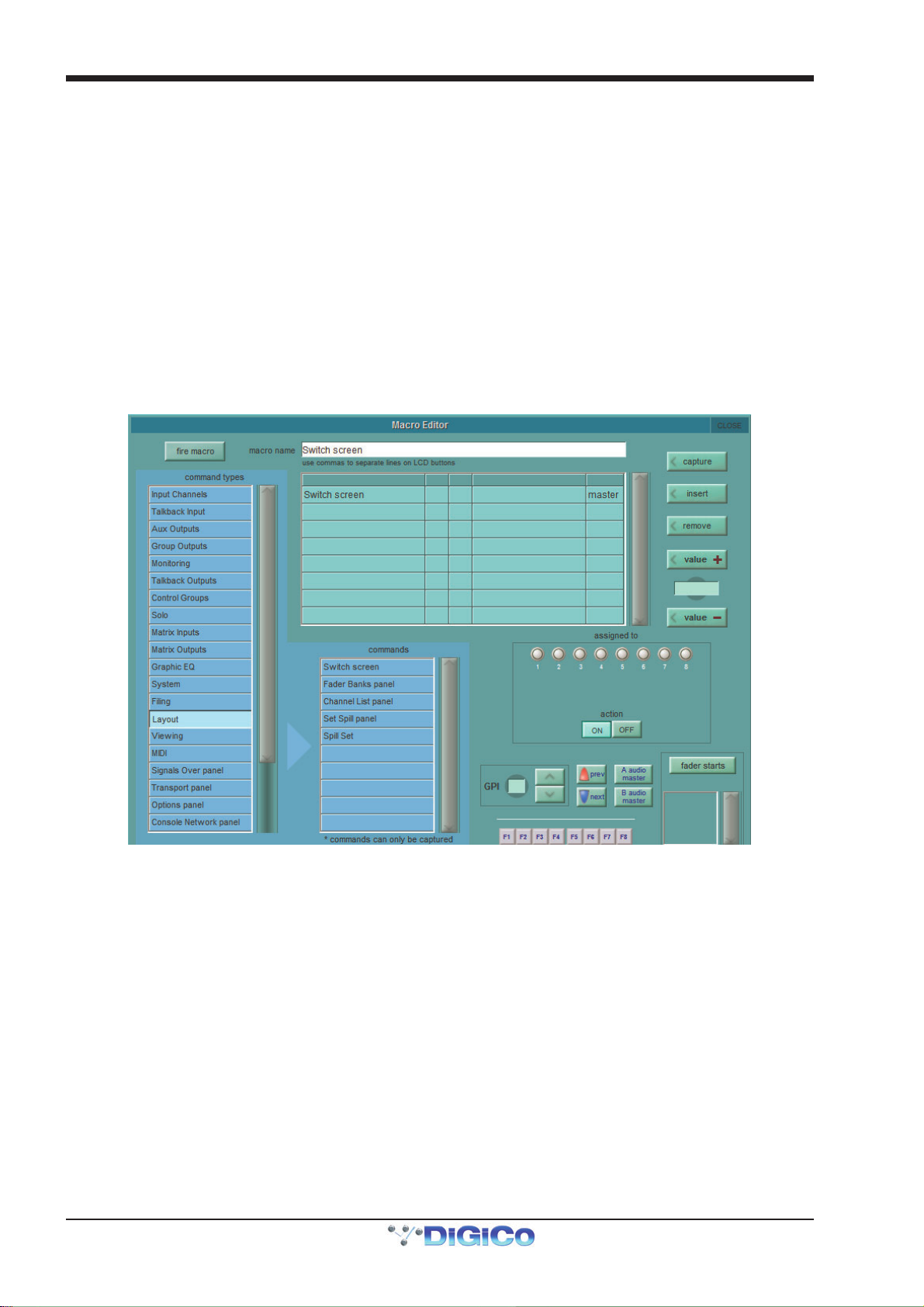
Chapter 2 - The Master Screen
button is touched, a macro is created with the default name macro n where n is an auto-incrementing number, and the Macro
Editor display (described below) is opened. A duplicate macro will contain all of the settings of its parent, apart from the name.
To edit a macro, touch the editor button below the duplicate button, followed by the macro you wish to edit. The Macro Editor
display (described below) will then open.
Macros can be assigned from the main Macros display without opening the Macro Editor by touching the assign button below
the editor button, touching the macro you wish to assign, and then pressing the button to which you wish to assign the macro.
Macros can be deleted by touching delete files. To delete all the macros in the list, touch select all, followed by confirm. To
delete one macro or a selection of macros, touch the macros you wish to delete followed by confirm. To delete a consecutive
range of macros, touch select range, touch the first and last macros included in the range to be deleted, and touch confirm.
2.13.13 The Macro Editor...............................................................
The Macro Editor is where macros are defined, including the commands included in the them and the control used to trigger them.
Virtually any command within the console can be assigned to a macro, ranging from opening master panels to adjusting in-channel
signal processing.
Note that fx parameters are only available once fx units are in use in the session.
The name of the macro being edited is shown at the top of the display. To switch to a different macro in the list, touch the new macro in the Macro display list (You may need to move the displays around the panel to access the list). To rename the macro, touch the macro name text box, type the new name using the on-screen or external keyboard, and touch OK. This name will be used in the Macros display and also in the LCD display within a smart key assigned to that macro.
Note that a line break can be inserted into the smart key macro name by typing a comma within the macro
name text.
The list beneath the macro name text box, lists the commands currently included in the macro. When there are multiple commands in the included commands list, they are triggered in the order in which they are listed. New commands are added to the
selected row in the list, overwriting any command previously in that row. To insert a row for a new command in between two
adjacent commands, touch the row above which you want to insert the command, then touch the insert button to the right of the
included commands list.
There are two ways of adding a command to the included commands list:
1. Touch the row in the list in which you want the command to appear, then touch the capture button, located in the top right-
hand corner of the display. The button turns pink to indicate that it is active. Any commands now actioned on the console will then
be added to the included commands list. Once all the desired commands have been actioned, deselect the capture button.
2-52
Page 87

Chapter 2 - The Master Screen
2. Touch the row in the list in which you want the command to appear, then touch one of the command types in the scrollable
command types list to the left of the display. This brings up a list of the commands within that command type in the scrollable commands list in the lower half of the display. Touch the desired command to bring it into the included commands list.
For commands associated with worksurface controls (all command types above System in the command types list), the
included commands list displays the command type (in the channel type column), the scope of channels included in the command
where appropriate (in the from and to columns), the command’s name (controller) and any value associated with the command.
For command types associated with the master panel (from System down), the included commands list displays the command,
along with any filename or value associated with it. The list can be scrolled if necessary using the scroll bar to its right.
The values in the from, to and value columns can be adjusted by using the Touch-Turn encoder and value + and value -
buttons to the right of the included commands list. Touch the box to be adjusted to assign it to the encoder and value buttons. The
present value is shown in the display in between the value buttons. If the value column displays something other than numeric
values, the options are cycled using the Touch-Turn encoder and value + and value - buttons (cycling for example, between on,
off and toggle). Values can also be typed in by touching the value box, typing the new value using the external or on-screen
keyboard, and touching OK.
To remove a command from the list, touch the command to be removed and touch the remove button to the right of the included
commands list.
The bottom-right of the Macro Editor is used to define what triggers the macro. The action buttons below the smart keys /
macro buttons are used to define whether pressing the button triggers a macro on or off command. Selecting a new trigger for
a macro automatically deselects any old trigger than might have been assigned.
On SD7, SD5 and SD10, Smart keys are selected by touching one of the eight bank buttons below the assigned to legend (causing the button’s ring to light green, indicating that it is selected) followed by one of its five smart keys. The smart key will then display the first command from the included commands list. The colour of the smart key can be chosen using the arrow buttons in the colour area below the smart keys. The selected colour is displayed between the arrow keys.
On SD8, SD9 and SD11 Macros are assigned in a similar way but directly to one of the 8 Macro buttons.
GPIs are selected by touching the GPI number box and using the Touch-Turn encoder, or by using the arrow buttons to the right
of the GPI number.
OSC assignments are selected by Touching the OSC button, then the number box and using the Touch-Turn encoder or by using
the arrow buttons to the right of the OSC/GPI area. (Note: OSC triggering only functions if External Control is enabled)
Function keys on the external keyboard are assigned by touching the F1 to F8 buttons at the bottom of the display.
The previous and next snapshot buttons on the control surface can also have macros associated with them, using the buttons
to the right of the GPI area.
It is also possible to fire a Macro in response to the Audio Master being changed. Different Macros can be assigned depending on
whether Audio Master is being switched to A or B. These are assigned using the A audio master and B audio master buttons
to the right of the GPI area.
Fader starts are configured in the bottom right-hand corner of the panel. Pressing the fader starts button opens a small configuration pop-up (shown below) as well as a Channel List display.
The four buttons above the fader starts button define what fader action fires the macro – fader up, fader down, mute off or
mute on. Once this has been defined, touching any channel row in the Channel List will add that channel fader to the fader
start, as listed below the fader starts button. If the ANY button is active, the Macro will fire when any of the associated faders
are moved to the specified state; if ALL is active, the Macro won't fire until all associated faders are in the specified state.
Note that fader starts are associated with the channel, not the fader – if a channel is moved, any fader start
functionality will move with it.
2-53
Page 88
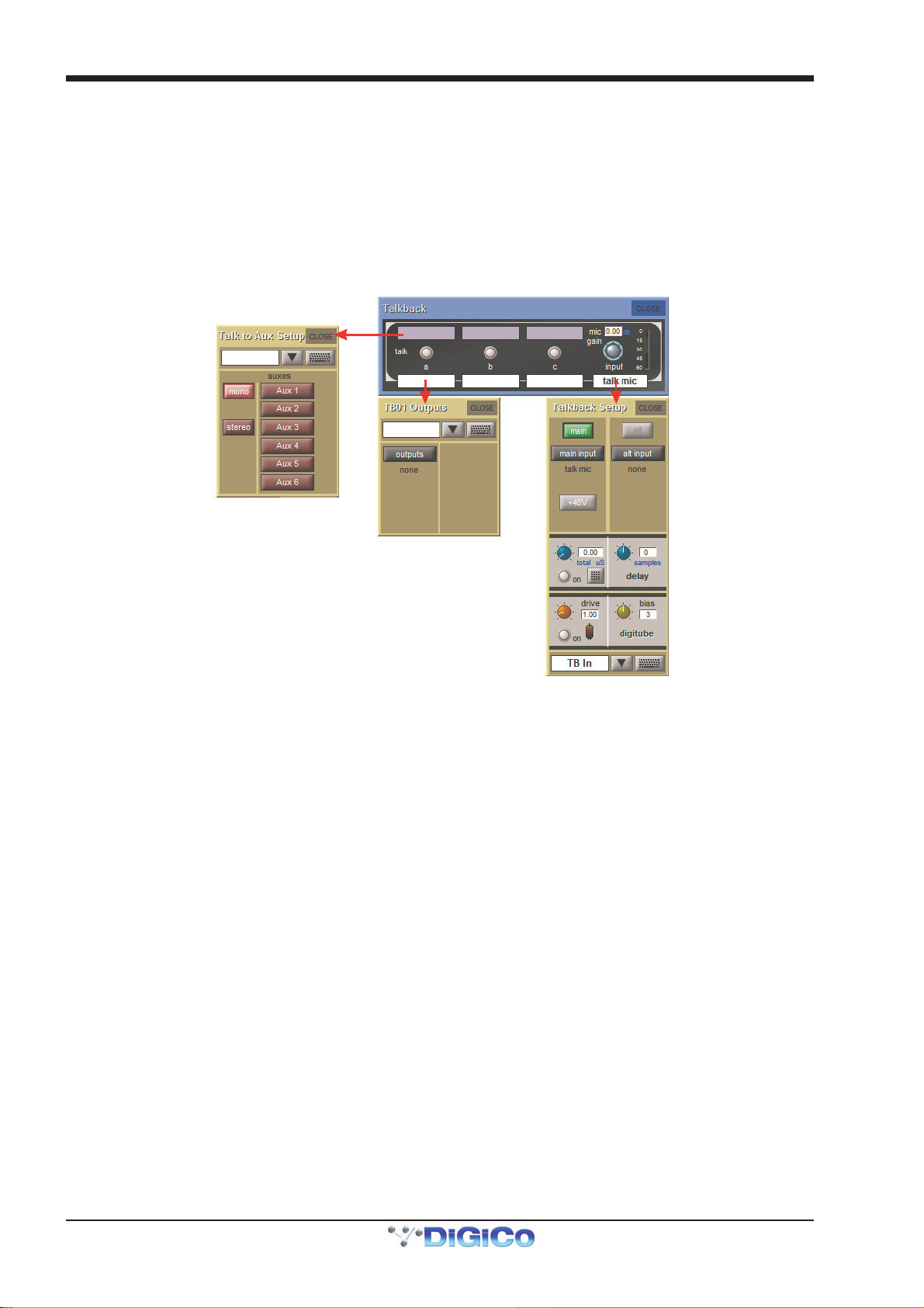
Chapter 2 - The Master Screen
Whenever a macro button is pressed, it performs what we call an On action. This is the first press of the macro button. The next
press of the same macro performs an Off action. These On and Off actions can be the inverse of each other, so instead of
having alternative presses of the macro button just toggle the state of a controller, you can program the macro button so that first
press is a definite mute on command and the 2nd press of the macro button is a definite mute off command. This has the advantage of being able to provide an indicator on the Macro button of the state of the controller. On and Off states can have different
colours and different text.
Macros can be tested by touching the fire macro button, located in the top left-hand corner of the display. Once the macro has
been fully configured, close the Macro Editor display.
2.13.14 Talkback ............................................................................
The Talkback display is opened by selecting Talkback from the Setup menu. This is where the talkback busses are configured.
In the right-hand side of the Talkback display, there is a mic input gain pot which is always assigned to the gain encoder in the worksurface talkback area. The pot’s gain value is indicated in dB in the box above the pot. The talkback signal level is shown in the meter to its right. Touching the white box below the gain pot opens up the Talkback Input display which consists of an input route button. The current route is displayed below the button. Pressing the button opens up the TB Input Route display, which functions in the same way as all other input routing panels.
To the left of the input section of the display, there are talk buttons with text boxes beneath them. Touching each button enables and disables the corresponding talkback button on the worksurface. The button rings red to indicate that the buss is active. Touching the text box beneath the button opens the TB Outputs display for that talk bus. This consists of a naming area and an outputs button. The first output currently selected is displayed below the button.
Pressing the button opens up the TB Output Routes display which functions in the normal way. The first selected route appears
in the text box below the talk button.
The three blue coloured text boxes above the buttons provide access to a panel allowing the selection of a number of aux
busses.
Once selected, the Talkback button will automatically activate the talk To Aux functions on those busses. This enables you to talk
to multiple Auxes of your choice at the press of a single button.
Talk To Auxes
In order to talk to individual or multiple of Aux outputs there is an assignable row of controls on Aux channels, controllable independently or from the Talkback panel which has a Talk to Aux Setup list for each Talk button.
This is implemented as a Talkback Input channel which uses a single engine processing channel to provide the aux sends. This
channel appears, in a default session, on its own in the last bank on the left of the console.
2-54
Page 89
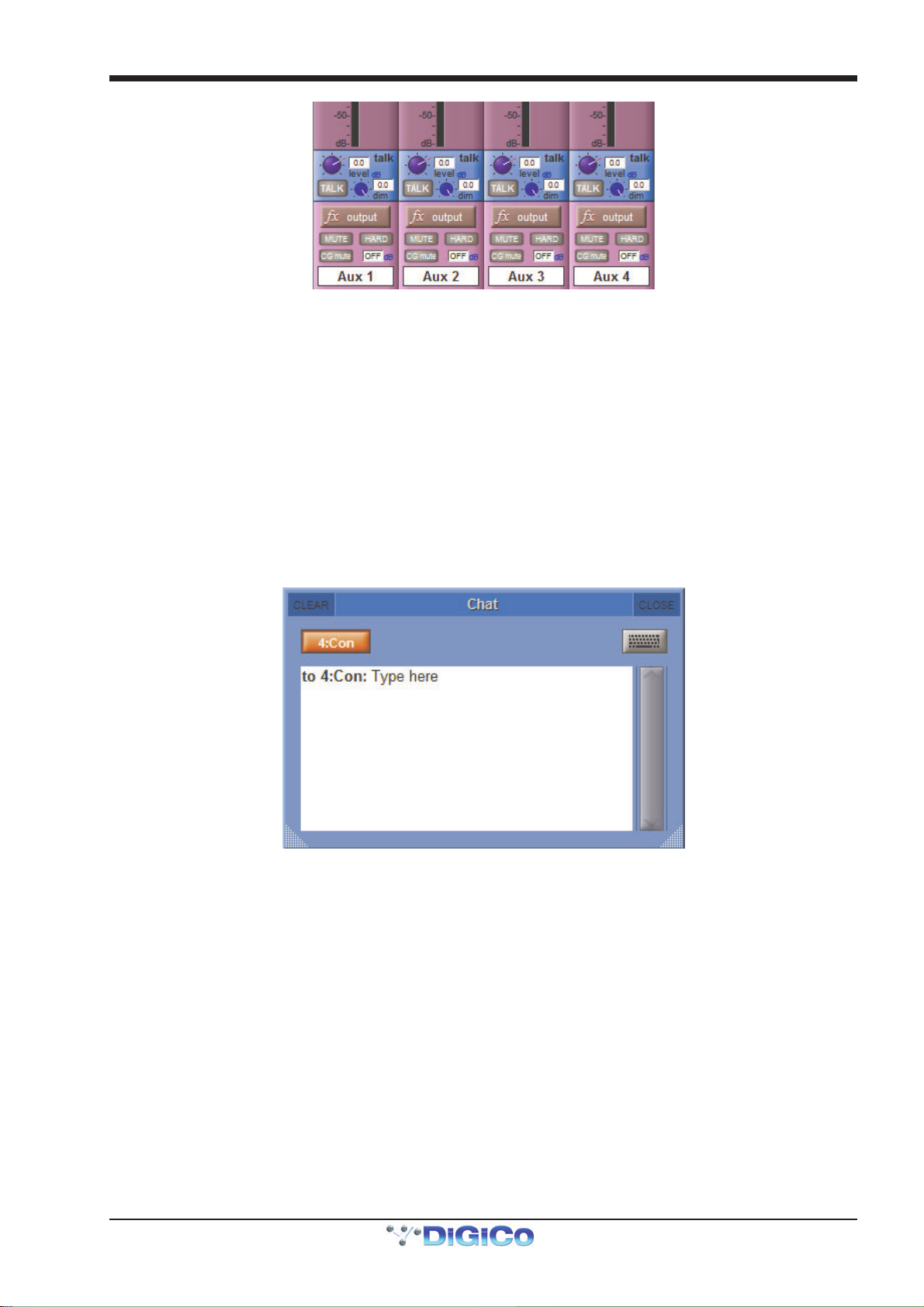
Chapter 2 - The Master Screen
On the Aux Output channels, hold one of the Assign buttons next to the row of assignable controls and then touch the talk area
of the screen. This will assign the selected rotary control and switch to the talk level and talk on/off.
These are used to switch Talk to Aux On/Off, control the level of talkback signal and set the level of dim when the talk is active. A
dim function is available for reducing the level of aux programme while the talk function is active. This is set using the 2nd
Function of the assigned controls.
The worksurface talk buttons can also be programmed to activate the Talk function on single or multiple user defined channels.
Open the Setup/Talkback panel and touch the label above the talk button, then select any combination of Mono and Stereo
Auxes to activate with that button.
2.13.15 Text Chat (SD5, SD7) ........................................................
Text messages can be sent from console to console on any MADI Port that is defined as "Console". This definition uses the last 8 audio inputs and outputs on the port to send text or video communications. The default setup of the SD7 defines MADI Port 4 as "Console". With MADI connections from one SD7's Port 4 In/Out to another SD7's Port 4 In/Out, open the Setup>Text Chat panel, press the 4:Con button to activate the link on that port and then type a message. When you press the keyboard Enter key, the message will be transmitted and will appear in the other console's Text Chat panel. This process is bidirectional so the other console can send messages back in a similar way. This communication can also be achieved across an optocore connection.
2-55
Page 90

Chapter 2 - The Master Screen
L
2.13.16 Video Link (SD7 Only).......................................................
The Setup>Video Link panel allows the routing of one of several different video signals to the console video screen. The worksurface buttons to select between these 3 sources can be found at the top of the console's centre section and are duplicated at the top of the on screen panel. There is also a Self button to send the console's own camera signal to the screen.
ocal Video Source
Selection
Video to send to
other consoles
Activate feed
To define the source associated with each button, touch the white label box below the on screen label and a drop down menu
will appear.
Potential sources include the console's two external video inputs (Ext 1 & Ext 2) located on the back panel and any optocore
equipped SD7 engines that are connected. Optocore engines are identified by their Optocore Loop number (normally 1) and their
Optocore ID which can be seen and set at the top of the console's Network panel).
The lower part of the Video Link panel determines which video source is fed from the console to the video network. Only one source can be sent at one time and this is done by pressing the Feed button beneath the required source.
Select the appropriate video format using the NTSC and PAL buttons, ensuring that all connected consoles are using the same
format.
The console's camera feed can also be sent as a Mirror image using the on screen buttons.
NOTE: The Options menu, which will appear beneath Video Link in the Setup menu if Waves is active, is
described in Section 5 of this chapter.
2-56
Page 91

Chapter 3 - Connections & Multi Console Setups
SD Software Reference Manual
Chapter 3:
Connections
& Multiple Console Setups
3-1
Page 92

Chapter 3 - Connections & Multi Console Setups
FOH & MONITORS
SHARED
LOCAL RACK
M
3.1 Console Audio Connections
SD Series console external audio connections can be made using either BNC MADI (AES10), Optocore or the DiGiCo Cat5e
Connection.
There are 2 types of MADI connecftion available. A DiGiCo Stage rack can be connected to a console via a bi-directional MADI
connection will have upto 112 channels (56 n, 56out) of audio plus the control data for the Rack (located on CH57). A Bi directional standard MADI stream will contain upto 128 channels of Audio (64in, 64out) and can be connected to any 3rd party device
that has MADI connection.
A DiGiCo Cat5e connection is a Bi Directiional up to 64 Channe l interface that uses STP Cat5e Cable with interference suppressors fitted on each end used to connect D-Racks and SD9 and SD11 Consoles.
3.2 Multi-Console setups
3.2.1 FOH & Mons sharing a stage DiGiRack (MADI) ..................
It is possible for 2 SD7 consoles to share the inputs from a remote DiGiRack by using the 2 sets of MADI ports on the rack.
In this situation, only one of the consoles can control the rack functions such as the analogue gain of the mic pre amp and the
phantom power switching.
The suggested setup for two SD7 consoles which are sharing the same racks is as follows:
STAGE RACK
WITH DIGIRA CKS
USING MADI ONLY
AUX MADI
IN/OUT
ENGINE B
MADI PORT 1
IN/OUT
ENGINE B
ADI PORT 2
IN/OUT
MAIN MADI
IN/OUT
MAIN MADI
IN/OUT
MADI
SPLIT
MADI
SPLIT
ENGI NE A
MADI PORT 1
IN/OUT
ENGI NE A
MADI PORT 2
IN/OUT
AUX MADI
IN/OUT
Uni-Directional Gain Tracking
FOH has control of the Analogue Gains
and Monitors can track this
ENGIN E A
MADI PORT 1
IN
ENGINE B
MADI PO R T 1
IN
ENGINE A
MADI PORT 2
IN/OUT
OPTIONAL
LOCAL RACK
ENGINE B
MADI PORT 2
IN/OUT
MONITORS
Audio Sync = MADI IN ON PORT 1
FOH
Audio Sync = MASTER
MAIN MADI
IN/OUT
AUX MADI
IN/OUT
When using DiGiRacks on MADI, because each SD7 has 2 engines there is a requirement to split the rack's MAIN and AUX MADI
OUT signals to feed the second console's MADI IN ports.
The recommended connection between the Monitor console and Stage Rack is a single MADI OUT from the Stage Rack's AUX
MADI connected to the console's MADI 1 IN..
The FOH (Master console) is connected via MADI IN and OUT to the stage rack.
A similar method can be used if the Monitor console requires gain control and the FOH console will track the gain changes.
MADI OUT from the Stage Rack's AUX MADI connected to the FOH console's MADI 1 IN..
The Monitor (Master console) is connected via MADI IN and OUT to the stage rack.
3-2
OPTIONAL
Page 93

Chapter 3 - Connections & Multi Console Setups
FOH & MONITORS
SHARED
LOCAL RACK
M
I
1) Open the Setup>Audio I/O panel, select the shared rack port from the port's list (eg Port 1) and then press the Shared button
for that rack. Do this on both consoles and the rack control functions Isolate/Receive Onlly/Full Control will become available.
2) One console should be fully connected to the racks using the Setup>Audio I/O panel's Full Control button for the Shared
racks.
3) The operators should agree on and set a level of analogue gain that provides enough headroom for the required application.
4) The second console should connect to the Shared racks in Receive Only mode
5) Gain Tracking (the Track buttons at the top of the Input channel screen) can be switched on for the console that is in Receive
Only mode for all the channels that are being shared.
6) When an analogue gain control is changed on the "Master" console, the "Slave" console's analogue gain should reflect the
changes and the digital trim control should compensate for this change by moving by the same amount in the opposite direction.
Relative Gain-Tracking - Snapshot Recalls Total Gain
“Relative Gain-Tracking” is implemented as a “Snapshot Recalls Total Gain” option at the bottom of the Snapshot Global Scope
panel. When a snapshot recalls an input channel trim, it compares the snapshot’s stored analogue gain against the current gain
on the channel’s input socket. If there’s a difference it offsets the value recalled by the trim. This only happens when the
socket’s rack is in Receive Only, or the analog gain is not in Recall Scope.
3.2.2 FOH & Mons sharing a stage SD Series Rack (MADI).........
When using SD Racks the setup is very similar but the rack split from an SD Rack can be acheived without an external splitter. The
SD rack has two built in split outputs which can each provide a 56 channel MADI stream at 48KHz. The added advantage of the
SD rack split is that it can be set to provide an automatically gain tracked MADI stream. This can be set on the rack itself or from
the Audio I/O panel on the console. This means that the receiving console does not need to provide the gain tracking facility.
STAGE RACK
2 x 48KHz
MADI SPLITS
WITH SD-RACKS at 48KHz
USING MADI ONLY
AUX MADI
IN/OUT
ENGINE B
MADI PORT 1
IN/OUT
ENGINE B
ADI PORT 2
IN/OUT
MAIN MADI
IN/OUT
MAIN MADI
IN/OUT
ENGIN E A
MADI PORT 1
IN/OUT
ENGIN E A
MADI PORT 2
IN/OUT
AUX MADI
IN/OUT
Uni-Directional Ga in Tracking
FOH has control of the Analogue Gains
and Monitors can track this
ENGINE A
MADI PORT 1
IN
ENGINE B
MADI PORT 1
IN
MONITORS
ENGINE A
MADI POR T 2
IN/OUT
OPTIONAL
LOCAL RACK
ENGINE B
MADI POR T 2
IN/OUT
Audio Sync = MADI IN ON PORT 1
FOH
Audio Sync = MASTER
MAIN MAD
IN/OUT
AUX MADI
IN/OUT
Note - The console that is controlling the gains should be set to Setup / Audio Sync = Master and the console
that is tracking should be set to Setup / Audio Sync = MADI 1
OPTIONAL
3-3
Page 94

Chapter 3 - Connections & Multi Console Setups
CONNECTION W ITH OPTICAL FIBRE
MONITORS
O
BOPTO
NGINE
LOCAL RACK
3.2.3 FOH & Mons sharing DiGiRacks (Opto V220) ......................
If 2 SD7's and DiGiRacks are connected with optical fibre, a similar setup can be achieved in the following way:
USING DiGiRAcks on Optocore V220
RACK OPTO ID 30 RACK OPTO ID 32
OPTO A
OPTO A
MADI PORT 2
AUX MADI
OPTO B
OPTO B
ENGINE A
ENGINE A
IN/OUT
IN/OUT
OPTO A
ENGINE B
MADI PORT 2
OPTO B
OPTION AL
REDUNDANT
LOOP
OPTO A
ENGINE B
IN/OUT
MAIN MADI
IN/OUT
OPTO B
Audio S ync = Optocore
A
E
OPTO B
A
O
T
P
OPTO A
B
E
N
I
G
N
E
FOH
Audio Sync = Optocore
ENGIN E A
MADI PORT 2
IN/OUT
OPTIONAL
LOCAL RA CK
ENGINE B
MADI PORT 2
IN/OUT
MAIN MADI
IN/OUT
AUX MADI
IN/OUT
OPTIONAL
In this setup, you are limited by Optocore firmware Version 220 to four SD7 engines (2 consoles) and four Optocore connected
racks. The system can only run at a sample rate of 48KHz.
Only one of these consoles will be able to use the outputs on Optocore connected racks and this console must be set to Optocore
ID1 (Engine A) and ID2 (Engine B), The other console should be set to ID3 (Engine A) and ID4 (Engine B).
These IDs are set from the Network panel in the Master screen.
The four racks can have any Optocore ID in the range ID30 to ID33. In the above example they have ID30 and ID32. These IDs are
set on the racks themselves.
The connections that should be made are shown in the diagram, as follows:
The fibre optic cables connect between each device on the optic loop, and connect an “A Port” to a “B Port”. You should not
connect the optic cables in A-A or B-B configurations. The cables connect between each device to form a closed loop. This is
necessary for the redundant loop to operate correctly.
The diagram also shows each console having a local MADI connected DiGiRack using BNC MADI cables.
The DiGiRack Main MADI Port is connected to one of the MADI Ports on Engine A and the Aux MADI Port is connected to the same
numbered port on Engine B.
Open the Setup > Audio Sync panel and set the Sync source to be Optocore. Do this on both engines of both consoles.
Save and Send the Session from the A engine on each console to its B engine and Mirror each pair of engines.
Now open the Setup > Audio IO panel on the A engine of both consoles, and press the Conform All Ports button in the bottom
left corner. The console will “look” down the connected optical fibre cables and auto discover and conform all the racks it can
find. In this example, they will find 2 optic stage racks. This function will be automatically mirrored to the B engine on each
console.
In its default setup, none of the optocore connected DiGiRacks will be defined as shared. This means that either console will be
able to control the rack and adjust Mic Amp Gain, Phantom Power, output pads etc.
If you are happy for either desk to control the racks, then you can leave the sessions with these default settings. Making changes
to this default state allows you to define the shared status of each rack. If you set a rack to be in full control, then that console
3-4
Page 95

Chapter 3 - Connections & Multi Console Setups
CONNECTION W ITH OPTICAL FIBRE
MONITORS
OPT
BOPTO
N
N
E
I
I
LOCAL RACK
will have full control of the rack. If you set a rack to be in receive only mode, then that console will not be able to make changes to
mic amp gain etc, but will “see” the changes made by the other console. This is necessary for Gain Tracking to function. The third
option is isolate, and when in this mode, the console will not be able to make changes, nor see changes made by someone else.
Gain tracking will not work if the rack is set in isolate mode.
To set a console as the master controller for the racks : In the Audio IO Panel, select the appropriate stage rack. Press the Splits
and Sharing button. In the section titled Selected Rack, press the shared button. It will default to the Isolate setting. Then press
the full control button. A warning will remind you that going into full control may affect the live audio.. then press Yes. If required,
repeat this process for the second stage rack.
To set racks to be in receive only mode : In the Audio IO Panel, select the appropriate stage rack. Press the Splits and Sharing
button. In the section titled Selected Rack, press the shared button. It will default to the Isolate setting. Then press the receive
only button. A warning will remind you that your session will change to correctly reflect the actual settings on the rack.. then
press Yes. If required, repeat this process for the second stage rack.
3.2.4 FOH & Mons sharing SD Series Racks (Opto V221) ............
using SD Series Racks on Opto core V221
RACK OPTO ID 11 RACK OPTO ID 12
OPTO A
OPTO B
OPTION AL
REDUNDANT
LOOP
ENGINE B
OPTO A
ENGINE B
MADI PORT 2
IN/OUT
MAIN MADI
IN/OUT
UP TO 14
SD SERIES
RACKS ON
ONE LOOP
OPTO B OPTO A
OPTO A
OPTO B
OPTO B
ENGINE A
ENGI NE A
MADI PORT 2
IN/OUT
AUX MADI
IN/OUT
OPTO ID 3 and 4
Audio Sync = Optocore
A
I
G
E
OPTO B
A
O
OPTO A
B
E
N
I
G
N
E
FOH
OPTO ID 1 and 2
Audio Sync = Optocore
ENGINE A
MADI PORT 2
IN/OUT
OPTIONAL
LOCAL RACK
ENGINE B
MADI PORT 2
IN/OUT
MAIN MAD
IN/OUT
AUX MAD
IN/OUT
It is possible for up to 5 DiGiCo consoles to share the inputs from remote stage SDRacks using optical fibre cables. It is also
possible for the output cards in the SDRacks to be allocated to the consoles on a card by card basis.
The following example describes how to set up 2 consoles with a pair of stage racks in a Front of House & Monitors configuration. The connections that should be made are shown in the diagram, as follows.
The fibre optic cables connect between each device on the optic loop, and connect an “A Port” to a “B Port”. You should not
connect the optic cables in A-A or B-B configurations. The cables connect between each device to form a closed loop. This is
necessary for the redundant loop to operate correctly.
The diagram also shows each console having a local MADI connected SDRack. These are connected using pair of BNC MADI
Cables between one of the MADI ports on the console and the Main MADI ports on the SDRacks. Additional redundant MADI
cables can be used, connected the redundant MADI ports on the console to the Aux MADI Ports on the SDRack.
OPTIONAL
3-5
Page 96

Chapter 3 - Connections & Multi Console Setups
Console Setup & Operation
To ensure correct operation of this system, it is necessary to ensure that the console and session settings are correct.
Each Optically connected device must have a unique ID. On each console, open the Network panel on the Master Screen. From
the drop down list at the top of the panel, set the ID of each console. We would recommend setting the FOH console to ID1 and ID2
and the monitor console to ID3 and ID4. Even numbered ID's are used for Redundant engines in Mirrored engine setups therefore if
you were mirroring two single engine consoles, they should be set as ID1 for the FOH console and ID3 as the Monitor console.
Similarly, each SDRack should have it’s ID set. Rack ID’s start from 11; this example uses Optocore ID’s 11 & 12 for the 2 connected racks.
On each console, ensure that the session sample rates are the same. The sample rate is set in the Files > Session Structure
panel.
Open the Setup > Audio Sync panel and set the Sync source to be Optocore. Do this on both engines of both consoles.
Save and Send the Session from the A engine on each console to its B engine and Mirror each pair of engines.
Then open the Setup > Audio IO panel on the A engine of both consoles, and press the Conform All Ports button in the bottom
left corner. The console will “look” down the connected optical fibre cables and auto discover and conform all the racks it can
find. In this example, they will find 2 optic stage racks.
If the conformed racks in each of the engine's Audio IO panels do not match the other console, then the system will not map correctly. Before the system is mapped, you should allocate any SDRack output cards. Press the Setup Optocore button select / deselect output cards as required. Once this is complete, press the Remap All Optocore button.
[For more detailed information on the Optocore Setup, please refer to Optocore_221_User_D.pdf which is available for download
from the Support section of the DiGiCo website and as an Appendix to this manual.]
In its default setup, none of the optocore connected SDRacks will be defined as shared. This means that either console will be
able to control the rack and adjust Mic Amp Gain, Phantom Power, output pads etc.
If you are happy for either desk to control the racks, then you can leave the sessions with these default settings. Making changes
to this default state allows you to define the shared status of each rack. If you set a rack to be in full control, then that console
will have full control of the rack. If you set a rack to be in receive only mode, then that console will not be able to make changes to
mic amp gain etc, but will “see” the changes made by the other console. This is necessary for Gain Tracking to function. The third
option is isolate, and when in this mode, the console will not be able to make changes, nor see changes made by someone else.
Gain tracking will not work if the rack is set in isolate mode.
To set a console as the master controller for the racks : In the Audio IO Panel, select the appropriate stage rack. Press the Splits
and Sharing button. In the section titled Selected Rack, press the shared button. It will default to the Isolate setting. Then press
the full control button. A warning will remind you that going into full control may affect the live audio.. then press Yes. If required,
repeat this process for the second stage rack.
To set racks to be in receive only mode : In the Audio IO Panel, select the appropriate stage rack. Press the Splits and Sharing
button. In the section titled Selected Rack, press the shared button. It will default to the Isolate setting. Then press the receive
only button. A warning will remind you that your session will change to correctly reflect the actual settings on the rack.. then
press Yes. If required, repeat this process for the second stage rack.
3-6
Page 97

DiGiCo Optocore V221
Appendix A
DiGiCo
Optocore V221
For SD Rack Optocore Operation
Issue E - May 2014
A1-1
Page 98

DiGiCo Optocore V221
A1-2
Page 99

DiGiCo Optocore V221
Content s (Appendix A)
A1.1 Optocore V221 - Introduction ...................................................A1-4
A1.1.1 System Overview...................................................... .......A1-4
A1.1.2 Opto V220 (DiGiRacks) and Opto V221 (SD Racks).......A1-5
A1.1.3 Replacing DiGiRacks with SD Racks ..................... .......A1-5
A1.1.4 Replacing SD Racks with DiGiRacks ..................... .......A1-7
A2.1 The Audio IO Panel.....................................................................A1-8
A2.1.1 Layout ....................................................................... .......A1-8
A2.1.2 Quick Start Guide for SD V370+ and Optocore V221.......A1-8
A2.1.3 Audio Sync.............................................................. .......A1-12
A2.1.4 The Port List ........................................................... .......A1-12
A2.1.5 Managing Ports ...................................................... .......A1-12
A2.1.6 SD Rack Splits........................................................ .......A1-13
A3.1 SD Series Dual Loop Optocore Systems ...................... .......A1-13
A3.1.1 Important Considerations...................................... .......A1-13
A3.2.1 Setting up a Dual Loop System ............................ .......A1-14
A3.2.2 Console Snd/Rcv Ports ......................................... .......A1-14
A3.2.3 Single Loop Console on Loop 2 ........................... .......A1-15
A1-3
Page 100

DiGiCo Optocore V221
A1.1 Optocore V221 - Introduction
A1.1.1 System Overview ...............................................................
The new V221 DiGiCo Optocore fibre system provides users with a highly flexible system. In order for correct and safe operation of the
system, the basic principles need to be understood.
A DiGiCo fibre loop now supports up to 10 SD Engines (5 Redundant Consoles) and 14 Racks. These are identified as follows.
NOTE: For more information on Dual Loop Optocore systems please refer to the relevant section of this
Appendix
SD Engines are allocated ID’s between 1 and 10. SD7 Consoles with 2 Engines are allocated ID’s in consecutive pairs.. 1&2, 3&4 etc.
SD8 Consoles only have a single Engine and therefore only have a single ID. If 2 SD8’s are to be configured as a redundant pair, then
their ID’s should be allocated consecutively, in the same way that SD7 redundant Engines are paired.
SD Racks (and Optocore enabled D-Racks) are allocated ID’s between 11 and 24
NOTE: SD Racks can be set to Opto IDs 1 to 10 but the racks will not work on the Optocore loop if set to these
values. These values are used for factory testing only
As with previous Optocore systems, each device must have a unique ID. Additionally, each device must also be set to run at the same
speed. The previous Optocore system was fixed at 1G. The default speed for the new system is 2G.
Each Optocore loop (running at 2G) is capable of 504 channels of audio at either 48k or 96k. On an SD7, up to 2 loops can be
operated, providing up to 1008 channels of Optocore I/O
The Optocore Interface card (between Optocore connected devices and the SD Engine) supports 496 Input and 496 Outputs.
Inter-console IO is also catered for, allowing the transmission of Audio and Video between SD Engines.
This Optocore system allows for many more channels of audio than can be simultaneously routed into and out of the console. The limit of
simultaneously routed signals is 384 inputs and 384 outputs, including routing to local IO and MADI connected devices.
The V221 Optocore implementation provides additional functionality and features over the original Optocore system, as follows.
All inputs (to racks) are available to all consoles. However, it is possible for any console to opt-out of inputs, on a per-input card basis.
This means that when the channel routing panel is then opened, only the relevant inputs are accessible. This is particularly in a larger
shared system.
Output cards can be allocated / assigned to individual consoles. In practice, this allows a number of consoles sharing a single SD Rack to
have an output card each.
The Optocore system can be “locked” by any console, and reconfiguring of the system is then not possible until all consoles have been
placed in an unlocked state. Within a large shared system, this protection mechanism ensures that audio cannot be disrupted by another
console on the loop.
In order to configure these allocations, the Optocore system has to be mapped. This map tells each device on the loop which fibre
channels it is accessing – either to insert audio onto the loop or to extract audio from the loop.
Racks take audio in from external sources and insert them onto the loop. Consoles then extract this audio, which become the inputs into
the console
Consoles route signals out to the loop (so insert audio onto the loop) and then racks extract this to route out to external devices.
In order for this to operate correctly, a map is built telling each device where it inserts signals onto the loop, and where it extracts audio
from the loop.
The process of building this map has been made as simple as possible, and can be reduced to a few basic steps.
Connect the Consoles and Racks together, as required.
Input cards on the racks must be installed in a single block with no gaps between input cards. (So if your SD Rack only needs 5 input
cards, they must occupy the first 5 slots in the rack)
On every console (SD Engine), open Audio IO and press the “Conform All Ports”. This then will populate the Audio IO panel with all the
connected devices. Every console must have the same Audio IO panel configuration.
Allocate Rack output cards to consoles as required.
Press the “Remap All Optocore” button.
Please carefully follow the procedure in the Quick Start section later in this manual.
A1-4
 Loading...