

Page 1
DiGiCo
SD Rack
Provisional - October 2010
SD Rack
1-1
Page 2

SD Rack
1-2
Page 3

SD Rack
Contents
1.1 Introduction................................................................................ .......1-4
1.1.1 Product Overview ................................................................1-4
1.2 SD Rack Power .......................................................................... .......1-5
1.3 SD Rack Clocking...................................................................... .......1-5
1.4 SD Rack Cards........................................................................... .......1-5
1.4.1 Analogue Mic/Line Input card (ADC) .................................1-6
1.4.2 Analogue Line Output card (DAC) .....................................1-6
1.5 Splits & Gain Tracking............................................................... .......1-6
1.5.1 Split Options ................................................................. .......1-6
1.5.2 Gain Tracking ............................................................... .......1-6
1.6 Using the SD Rack Menu System............................................. .......1-7
1.6.1 PSU Readings............................................................... .......1-9
1.6.2 I/O Card Code Versions ......................................................1-9
1.6.3 MADI Card Code Versions ........................................... .......1-9
1.6.4 Rack Defaults.......................................................................1-9
1.6.5 Main Display ................................................................. .......1-9
1.6.6 Optocore ID & Fibre Speed........................................ .......1-10
1.6.7 USB Rack Control .............................................................1-10
1.6.8 Rack Sync Source .............................................................1-10
1.6.9 Rack Sample Rate .............................................................1-10
1.6.10 Rack Routing Mode.........................................................1-10
1.6.11 Rack Main and Aux Splits ........................................ .......1-11
1.6.12 Rack Card Splits....................................................... .......1-11
1-3
Page 4
SD Rack
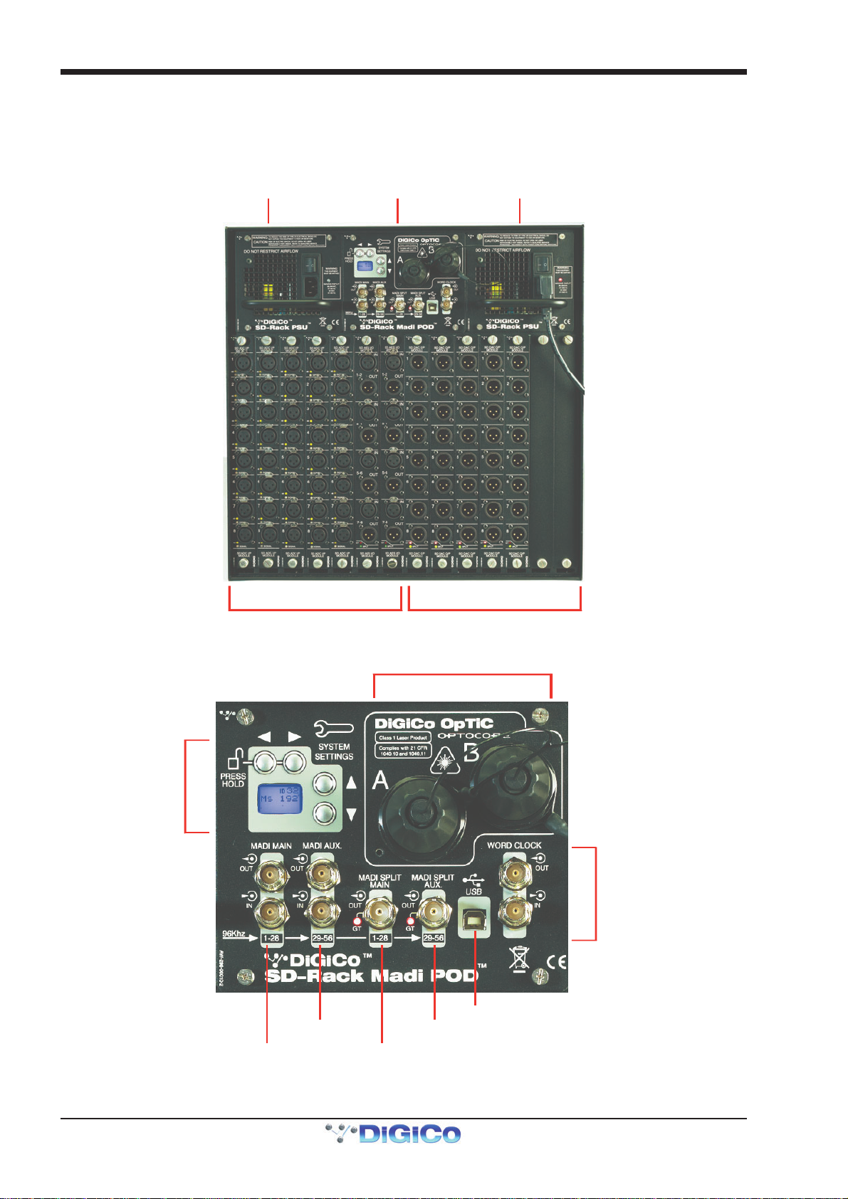
Hot Swappa ble
D
Hot Swappab le
Rack MADI/OPTO
Input or Bi directional C ards Output Cards
Optocore Interface
Word Clock
MAIN MADI Split
S
C
MAIN MADI
1.1 Introduction
1.1.1 Product Overview .................................................................
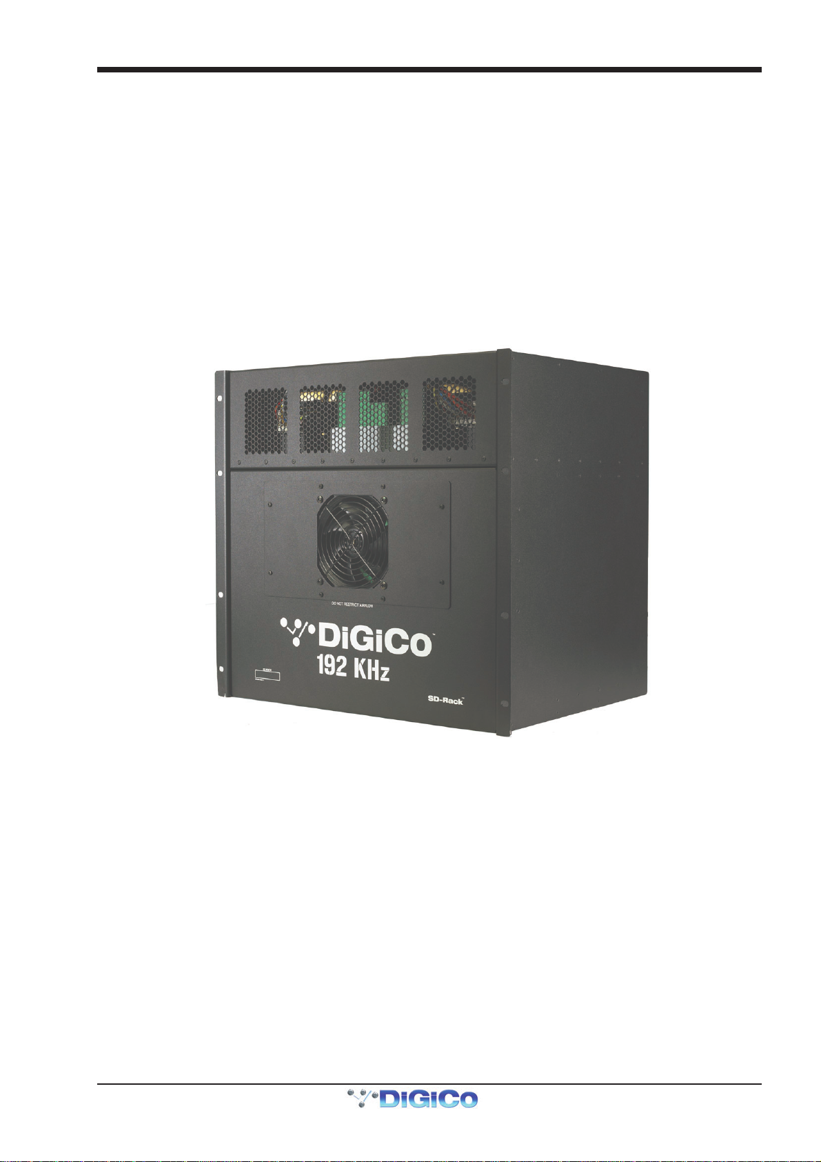
The DiGiCo SD Rack is........
ual Redundant PSU
Pod
Dual Redundant PSU
1-4
System
ettings
ontrols
AUX MADI
IN/OUT
External USB Control Port
AUX MADI Sp lit
Page 5

SD Rack
1.2 SD Rack Power
The SD rack has dual redundant hot swappable power supplies. The rack should be operated with both powersupplies on whenever
possible.
1.3 SD Rack Clocking
The SD Rack will receive clock sync from the connected console in normal operation. It can run run at 48KHz or 96khz when clocked by
the console. It is capable of running at 192KHz but this has not yet been implemented in current console software.
The SD Rack can also receive sync from its own internal clock at several different sample rates - see section 1.6.9 Rack Sample Rate
Additionally the rack can receive sync from an external word clock source when the word clock is connected to the rack's word clock in
port.
1.4 SD Rack Cards
Several rack I/O card options are available - I/O cards normally provide blocks of 8 signals.
A rack can be fitted with up to 14 I/O cards providing up to 56 inputs and 56 outputs.
Card options are:
Analogue Mic/Line Input card on XLR
Analogue Line Output card on XLR
AES Input card on XLR or BNC
AES Output card on XLR or BNC
AES Bidirectional I/O card on XLR or BNC
Aviom card (16 outputs occupying 2 rack slots) - CAT5 connector
AES42 Mic Input card on XLR
1-5
Page 6

SD Rack
1.4.1 Analogue Mic/Line Input card (ADC)..................................
The 8 Mic/Line input ADC card has 2 indicators on each socket.
The orange indicator shows the status of +48V Phantom Power On/Off.
The green indicator shows signal present and this turns red when the signal is close to clipping.
1.4.2 Analogue Line Output card (DAC)......................................
The 8 Line output DAC card has 2 indicators at the bottom of the card.
The red indicator shows the status of Gain Tracking On/Off.
The yellow indicator shows the status of the card Split On/Off.
1.5 Splits & Gain Tracking
1.5.1 Split Options ........................................................................
The SD Rack has several different Split options.
1) Each input slot (block of 8 sockets on an input card) can be split to its relevant output slot. So slot 1 would be split to slot 8, slot 2 to
slot 9 and so on. These split signals can be automatically Gain Tracked so that any change in the analogue gain on the input socket is
compensated by the opposite change in digital trim on the relevant output socket.
The output cards have LED indicators showing Split ON/OFF and Gain Tracking ON/OFF status.
2) There are 2 dedicated MADI split ports on BNC connectors labelled MADI Split Main (MadiSM) and MADI Split Aux (MadiSX).
These ports can provide either 2 independent split signals at 48KHz or a pair of split signals that contain MADI channels 1-28 and 29-56
at 96KHz.
These outputs can also have automatic Gain Tracking applied to them on a per split basis. Eg. Main Split with Gain Tracking On and Aux
Split with Gain Tracking Off
1.5.2 Gain Tracking .......................................................................
Gain Tracking can be controlled from the Rack LCD Menu system or optionally by an SD Series console.
With Gain Tracking switched ON the digital trim on the split outputs works in direct relation to the analogue gain that is applied to the
relevant (same numbered) input socket. Any change in the analogue gain at the input results in the opposite change being applied to the
digital trim of the output split socket.
If the analogue gain of an input socket starts at 0dB and with Gain Tracking On is raised to +10dB, the output split level will remain
constant because it will have had a -10dB change applied to it in real time.
The correct procedure to follow is to set an acceptable level of analogue gain on each input before switching the Gain Tracking function
on. Once the Gain Tracking function is active it should not be switched off without careful consideration.
There is also a Gain Track Reset function which sets the split output digital trim to zero. This function should also be treated with due care
because using it on an active split will potentially change the output level by a large amount.
1-6
Page 7

SD Rack
1.6 Using the SD Rack Menu System
The LCD Menu System on the rack MADIPod is normally in a locked state and cannot be accessed.
The main display will be visible and if the rack is not connected to an SD console the background colour will be light blue.
If an SD console is connected and the rack is correctly receiving control data from it, the display will flash green.
Pressing and holding the 2 buttons marked with left and right arrows for 2 seconds unlocks the Menu System. During the 2 seconds the
display will be red and say "Locked" and when unlocked, the display will turn green and say "Unlocked".
The Up/Down buttons scroll through the pages in the Menu System and the Left/Right buttons are used to select each item within pages
that have multiple items. When an item's value can be changed the Up/Down arrows are used for this.
If the rack is left in an idle state for 2 minutes, it will relock itself.
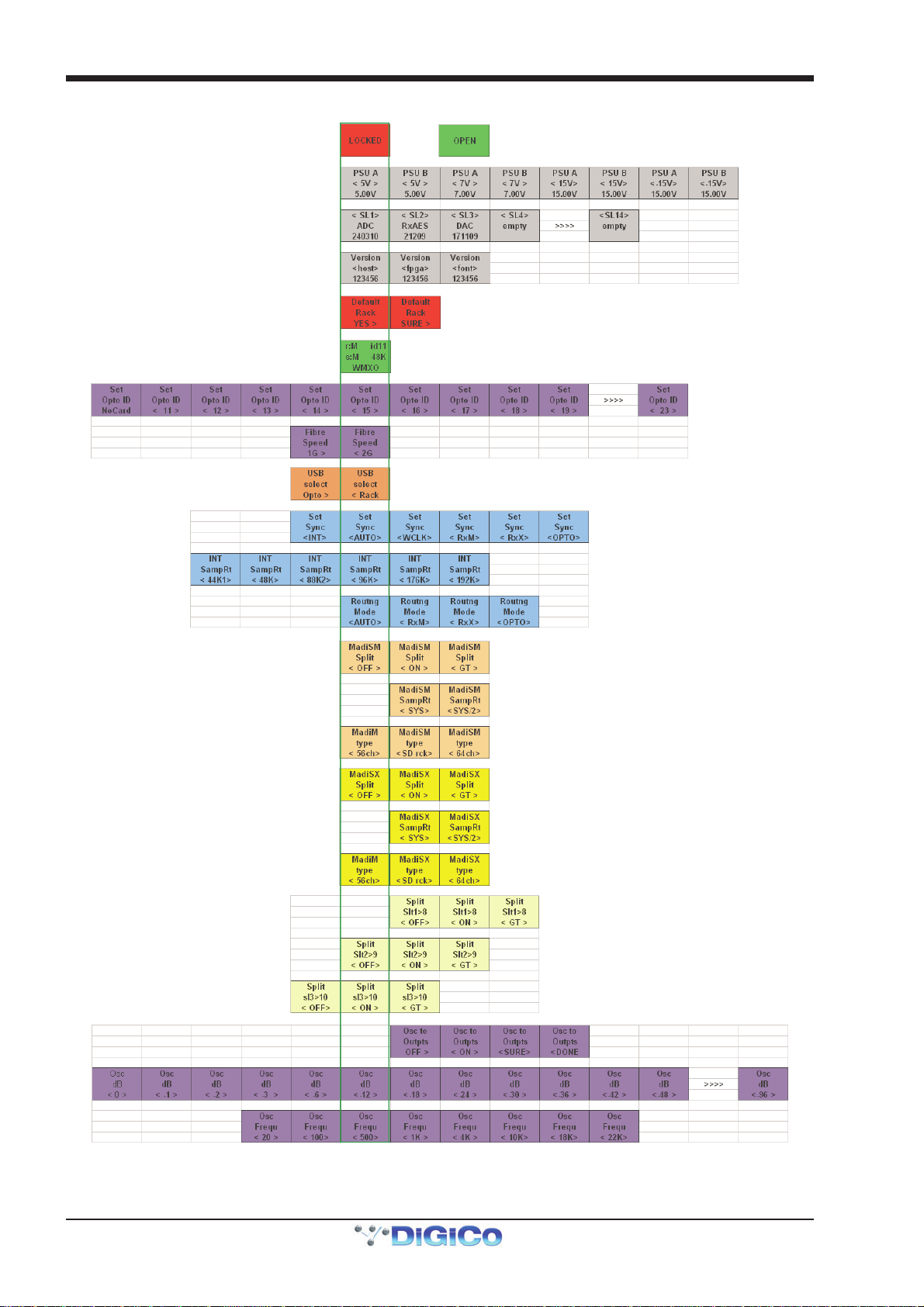
Please refer to the following diagram for menu navigation details.
1-7
Page 8
SD Rack
1-8
Page 9

SD Rack
1.6.1 PSU Readings.......................................................................
This page shows readings for all rack PSU voltages. No adjustment is possible from the menu.
1.6.2 I/O Card Code Versions .......................................................
This page shows the type of card detected in each rack slot and the firmware version installed on the card.
SLx indicates slot number in the range SL1 to SL14 reading left to right in the rack. Date codes are DD/MM/YY.
No adjustment is possible from the menu.
1.6.3 MADI Card Code Versions...................................................
This page shows the MADIPod firmware versions installed on the rack. HOST, FPGA and FONT date codes are DD/MM/YY.
No adjustment is possible from the menu.
1.6.4 Rack Defaults........................................................................
This page allows the user to set all rack parameters to their DEFAULT values.
When the display shows Default Rack - Yes>, press the Right arrow button to confirm.
The display will now show Default Rack - Sure>, press the Right arrow button to confirm.
Using the Left arrow button will navigate back from Sure> to Yes>.
1.6.5 Main Display .........................................................................
The main display is always visible when the Menu System is in a locked state.
It indicates:
r: = The type of input/output being routed (M=MADI, O=Optocore)
s: = The rack sync source (M=MADI, O=Optocore, Int=Internal, W=Word Clock
idxx = The Optocore ID of the rack
xxK = The sample rate being used by the rack (eg 48KHz)
WMXO = The sync priority order which defaults to Word Clock, MADI Main, MADI Aux, Optocore
An upward arrow (^) will appear underneath each of the available sources of sync.
Thus if there is no valid Word Clock or MADI input to the rack, it will automatically sync to Optocore if present.
If a valid Word Clock input is then connected to the rack, this will automatically become the sync source for the entire Optocore system.
If multiple valid Word Clock inputs are connected to different racks, the rack with the lowest optocore ID that is receiving a Word Clock will
become the sync source for the entire Optocore system.
1-9
Page 10
SD Rack
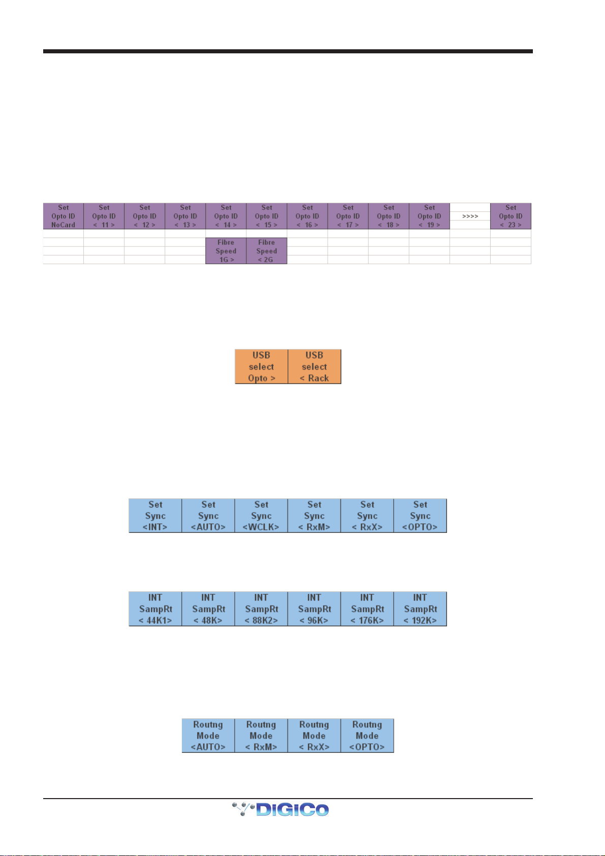
1.6.6 Optocore ID & Fibre Speed .................................................
These pages show the Optocore ID of the rack in range of 11 to 24 and the fibre speed which is either 1GB or 2 GB.
Each rack requires a unique ID so that it can be recognised by the rest of the Optocore system. To change the ID, scroll with the Left/
Right buttons until you reach the required number.
The rack fibre speed needs to be set to the same value as all other devices in the Optocore system. The Default is 2GB and this should
not be changed unless you have special requirements. There are two possible reasons to change the fibre speed to 1GB:
1) If you require distances of optical fibre greater than 350M between individual devices.
2) You require compatibility with Optocore's own I/O units, some of which will only operate at the 1GB fibre speed. Please consult your
Optocore device documentation for the fibre speed specifications.
NOTE: Using a fibre speed of 1GB will restrict the system's Optocore fibre channel count to 224 I/O at 96KHz.
1.6.7 USB Rack Control ................................................................
This page allows selection of which rack component can be addressed by the rack USB port.
When set to Opto >, the internal Optocore board can be addressed for the reprogramming of Optocore firmware - this is not required
unless under specific instruction from your distributor or DiGiCo Support.
When set to < Rack, the general rack control system can be addressed - this feature is not yet implemented (Nov 2010).
The Default setting is < Rack.
1.6.8 Rack Sync Source................................................................
This page allows selection of the rack sync source.
The Default setting is <AUTO> which allows automatic sync selection in the order WMXO as detailed in Main Display above.
This setting can be manually overridden and a specific sync source can be set as either:
<INT> = Internal sync - Rack is Master
<WCLK> = External Word Clock sync - Word Clock input is Master
<RxM> = MADI Main sync - MADI Main input is Master
<RxX> = MADI Aux sync - MADI Aux input is Master
<OPTO> = Optocore sync - Optocore is Master (normally the lowest numbered Optocore ID on the system)
1.6.9 Rack Sample Rate ................................................................
This page allows selection of the rack sample rate.
This is only possible if the Rack Sync Source is set to internal.
Available options are 44.1KHz, 48KHz, 88.2KHz, 96KHz, 176KHz and 192KHz
1.6.10 Rack Routing Mode ...........................................................
This page allows selection of the rack routing mode - which external source (MADI or Optocore) is being routed in and out of the rack.
The Default setting is <AUTO> which allows automatic routing selection where the routing mode follows the sync source setting.
This setting can be manually overridden and a specific sync source can be set as either:
<RxM> = MADI Main routing - Input and output routing via MADI Main
<RxX> = MADI Aux routing - Input and output routing via MADI Aux
<OPTO> = Optocore routing - Input and output routing via Optocore
1-10
Page 11

SD Rack
1.6.11 Rack Main and Aux Splits .................................................
This page controls the Main (MadiSM) and Aux (MadiSX) MADI Split functions.
1) Each split can be < OFF >, < ON > or ON with automatic Gain Tracking enabled (< GT >).
2) The sample rate of the split signal can also be set to be either the same as the rack's current sample rate < SYS > eg 96Khz or
< SYS/2 > which is half of the rack's current sample rate. eg Rack at 96KHz and split at 48KHz.
3) The MADI Type of the split can be set to standard 56 channel < 56ch >, 64 channel < 64ch > or < SD rck > which will emulate the
output of the SD rack and be recognised as such by the receiving MADI device. This last type would be useful if the split was feeding an
SD series console.
1.6.12 Rack Card Splits.................................................................
This page controls the individual output card Split functions.
Each card split can be < OFF >, < ON > or ON with automatic Gain Tracking enabled (< GT >).
Each input slot (block of 8 sockets on an input card) can be split to its relevant output slot. So slot 1 would be split to slot 8, slot 2 to slot 9
and so on.
1-11
 Loading...