

Page 1
DiGiCo S-Series User Guide – Issue J
Issue J for Software Version 2.5
Page 2
DiGiCo S-Series User Guide – Issue J
Page 3

DiGiCo S-Series User Guide – Issue J
Copyright © 2019 Digico UK Ltd
All rights reserved.
No part of this publication may be reproduced, transmitted, transcribed, stored in a retrieval system, or translated into any language in any form by any
means without the written permission of Digico UK Ltd. Information in this manual is subject to change without notice, and does not represent a
commitment on the part of the vendor. Digico UK Ltd shall not be liable for any loss or damage whatsoever arising from the use of information or any
error contained in this manual.
Software License Notice
Your license agreement with Digico UK Ltd, which is included with the S-Series console product, specifies the permitted and prohibited uses of the product.
Any unauthorised duplication or use of Digico UK Ltd software, in whole or in part, in print or in any other storage and retrieval system is prohibited.
Licenses and Trademarks
The S21 logo, S31 logo, S21 name and S31 name are trademarks, and Digico UK Ltd and the Digico UK Ltd logo are registered trademarks of Digico UK Ltd.
Digico (UK) Ltd
Unit 10
Silverglade Business Park
Leatherhead Road
Chessington
Surrey
KT9 2QL
England
Telephone: +44 (0)1372 845600
Fax: +44 (0)1372 845656
Email: sales@digiconsoles.com
WWW: http://www.digico.biz
Manual Issue and Date: Issue I – November 2019 – For Version 2.5
Licence Agreement
"Product": S-Series software product produced by Digico UK Ltd intended for use on Target Platform identified below.
"Target Platform": Digico S-Series Digital Console systems.
In return for the payment of the one-time fee, the Customer (identified at the end of this Agreement) receives from Digico UK
Ltd a licence to use the Product subject to the following terms and conditions.
1. The Product may be used without time limit by the Customer on the Target Platform.
2. The Customer must register the Product with Digico UK Ltd. Registering the Product is deemed an acceptance of the terms and
conditions in this agreement.
3. The Product and its licence are not transferable, and the Customer is not permitted to onward-license to any third party. The
Customer indemnifies Digico UK Ltd against any and all claims and actions arising from third party use of copies of the Product
made by the Customer.
4. The Customer agrees not to attempt to decompile the object code of the Product otherwise than in circumstances specifically
provided for by law, and then only after consultation with Digico UK Ltd.
5. The Customer agrees not to use, or licence the Product for use, with equipment other than the Target Platform.
6. The Customer agrees not to modify the Product without the prior written consent of Digico UK Ltd.
7. This Agreement applies to any enhancement or upgrades that may become available for the Product.
8. This Agreement does not transfer any right, title, or interest in the Product to Customer except as specifically set forth herein.
9. Digico UK Ltd reserves the right to terminate this Agreement upon breach, in which event Customer shall thereafter only be
authorised to use the Product to the extent that its contractual commitments to third parties require and then only where such
commitments relate to use of the Product as authorised in the foregoing provisions of the Agreement.
LIMITED WARRANTY - Digico UK Ltd warrants for a period of 1 year from the date of purchase of the Product, the Product will reasonably execute its
programming instructions when properly installed on the Target Platform. In the event that this Product fails to execute its programming instructions
during the warranty period, the Customer's remedy shall be to return the Product to Digico UK Ltd for replacement or repair at Digico UK Ltd option.
Digico UK Ltd makes no other express warranty, whether written or oral with respect of this Product.
LIMITATION OF LIABILITY - Except as otherwise expressly provided by law, (a) the remedies provided above are the Customer's sole and exclusive remedies
and (b) Digico UK Ltd shall not be liable for any direct, indirect, special, incidental, or consequential damages (including lost profit whether based on
warranty, contract, tort, or any other legal theory.)
This agreement is made under the Laws of England.
LICENCE NO: ..................................................................................................................................................
REGISTRATION DATE: ..................................................................................................................................
Page 4

DiGiCo S-Series User Guide – Issue J
Contents
1.1 The Console ..................................................................................................................... 1
1.2 Before You Start .............................................................................................................. 2
1.2.1 Worksurface Layout ........................................................................................................... 2
1.2.2 Layers and Banks ................................................................................................................. 3
1.2.3 Using the Control Surface .................................................................................................... 3
1.2.4 The Selected Channel .......................................................................................................... 4
1.2.5 The Under Screen Controls ................................................................................................. 5
1.3 The Expanded Views ....................................................................................................... 6
1.3.1 Display Expanded Views ...................................................................................................... 6
1.3.2 Channel Setup View ............................................................................................................ 7
1.3.3 Copy Channel ...................................................................................................................... 9
1.3.4 Presets .............................................................................................................................. 10
1.3.5 Channel Ganging ............................................................................................................... 11
1.3.6 Recording & Virtual Soundcheck ........................................................................................ 13
1.3.7 Group and Aux Setup View ................................................................................................ 14
1.3.8 Aux Sends View ................................................................................................................. 16
1.3.9 Input Routing View............................................................................................................ 17
1.3.10 EQ View ............................................................................................................................ 19
1.3.11 Dynamics 1 View ............................................................................................................... 21
1.3.12 Dynamics 2 View ............................................................................................................... 22
1.3.13 Control Group Setup ......................................................................................................... 23
1.3.14 Solo Channel Setup ........................................................................................................... 26
1.4 Customising the Layout ................................................................................................. 27
1.4.1 The Console Overview ....................................................................................................... 27
1.4.2 The Spill Set ....................................................................................................................... 27
1.4.3 Swap Banks ....................................................................................................................... 28
1.4.4 Set Master ......................................................................................................................... 28
1.4.5 Add/Delete Banks ............................................................................................................. 29
1.5 The Main Menu ............................................................................................................. 30
1.5.1 Session Management ........................................................................................................ 30
1.5.2 Snapshots.......................................................................................................................... 32
1.5.3 Fader Crossfades ............................................................................................................... 37
1.5.4 Preferences ....................................................................................................................... 38
1.5.5 UI Preferences ................................................................................................................... 39
Page 5

DiGiCo S-Series User Guide – Issue J
1.5.6 Solo Preferences ............................................................................................................... 40
1.5.7 Worksurface Preferences .................................................................................................. 40
1.5.8 Audio Sync ........................................................................................................................ 41
1.5.9 Macros .............................................................................................................................. 41
1.5.10 Presets .............................................................................................................................. 42
1.5.11 FX Rack.............................................................................................................................. 43
1.5.12 Graphic EQs ....................................................................................................................... 45
1.5.13 Send & Return Insert Routing ............................................................................................ 47
1.5.14 Matrix ............................................................................................................................... 47
1.5.15 AMM ................................................................................................................................. 48
1.5.16 System .............................................................................................................................. 50
1.5.17 Diagnostics ........................................................................................................................ 52
1.5.18 Extensions ......................................................................................................................... 52
1.5.19 Restart or Shutdown ......................................................................................................... 55
1.5.20 Upgrading Software .......................................................................................................... 55
1.6 DMI Cards ..................................................................................................................... 56
1.6.1 Fitting DMI Cards ............................................................................................................... 56
1.7 DMI-MADI Cards ........................................................................................................... 57
1.7.1 Connecting DMI-MADI ...................................................................................................... 57
1.7.2 Sharing Racks with DMI-MADI ........................................................................................... 60
1.7.3 Auto-Discovery of DMI Cards & Racks ............................................................................... 62
1.7.4 DiGiRack Compatibility ...................................................................................................... 64
1.7.5 DMI Card Details & Upgrade .............................................................................................. 65
1.8 DMI - Dante Cards ......................................................................................................... 66
1.9 DMI - ADC - DAC - MIC - AES Cards ................................................................................ 68
1.10 DMI - Waves - Hydra Cards ........................................................................................ 69
1.11 DMI - ME - A3232 Cards ............................................................................................. 70
Page 6
DiGiCo S-Series User Guide – Issue J 1.1 The Console
1
1.1 The Console
The DiGiCo S21 and S31 consoles each consist of a worksurface, an audio engine and a range of onboard inputs and outputs. They can
be connected using optional DiGiCo DMI Cards to a variety of DiGiCo racks and other audio input/output devices.
The console worksurface consists of 2 (S21) or 3 (S31) sections that can be configured to control up to 48 mono or stereo input channels,
10 VCAs, 16 mono or stereo busses plus a Master buss and a 10 Input x 8 Output Matrix.
The left and right sections (and the middle section if using an S31) have 10 assignable faders and 10 sets of assignable on-screen channel
controls, the right hand section also has a dedicated Master fader and mute, a Master/Solo meter, a set of 6 assignable encoder/switches
and worksurface navigation controls
The console's buss architecture is dynamic and can support mono and stereo configurations.
Multiple console setups can provide:
Front of House and Monitoring with shared stage racks and gain tracking.
S21 (above) and S31 (below)
NOTE: The S21 and S31 offer the same channel counts, buss counts and processing as each other. The only difference between the two
consoles is the number of worksurface sections and the placement of banks on a default session. In this manual, all screenshots are
taken from an S21 console. S31 and S21 sessions are interchangeable provided that the software version used on the console is not
earlier than the software version that the session was created in. There is no backward compatibility of sessions.
Page 7
DiGiCo S-Series User Guide – Issue J 1.2 Before You Start
2
1.2 Before You Start
There are certain general operating principles and terms that should be understood before continuing to use this manual. Please read
this chapter carefully before proceeding.
IMPORTANT NOTES:
S-Series v2.5 software is not compatible with any sessions created in preliminary (pre v1.0) versions of software.
It is compatible with all sessions created in v1.0 onwards.
Please delete old sessions (pre 1.0) to avoid potential issues and create a "New" session in v2.5.
The console power switch is situated on the rear panel.
Please ensure that any required DiGiCo I/O racks are connected to the console DMI cards and powered on before starting the console
itself to enable automatic discovery of the racks.
If using the inbuilt UB MADI interface with a computer running MacOS Catalina, use the Core Audio driver and not the UB MADI driver.
DMI cards are NOT "Hot swappable" so please ensure that the console is powered off before inserting or removing them.
We recommend that the first snapshot is used as a "Setup" Snapshot where all of your "session wide" settings like routing, Control
Group membership and Buss Modes (whether Busses are Groups or Auxes) are first stored.
Because these types of setting can be changed with Snapshot recall, it is advisable to save them all into this first snapshot before
creating any further Snapshots. In this way, the settings for all subsequent Snapshots will contain the same data and there should be
less requirement to adjust the Safe settings in the channels.
1.2.1 Worksurface Layout
IMPORTANT NOTE: The DVI Screen output will display a copy of the Master (right hand) screen but this must be connected to the HDMI
input of a suitable monitor using a standard DVI to HDMI adaptor (not supplied).
IMPORTANT NOTE: The GPI/O functionality is not yet implemented in v2.5.
MultiTouch Screen
Solo & Mute
Channel Faders
Assignable Encoder/Switches
Assignable Encoder/Switches
Spill Set
Headphone Level
Master/Solo Meters
Overview
Layer Up/Down
Snapshot Previous/Next
Master Fader
Rear Panel
SEE NOTE BELOW
AES I/O
DMI Slot 2
DMI Slot 1
Console USB
UB MADI Connector
Console Ethernet
12 Line Out
24 Mic/Line In
GPI/O
Word Clock I/O
DVI Screen Output
Page 8
DiGiCo S-Series User Guide – Issue J 1.2 Before You Start
3
1.2.2 Layers and Banks
The S-Series worksurface is divided into Layers and Banks. Each Layer contains 2 (S21) or 3 (S31) Banks of 10 channels, and the layer
which is currently active on the control surface is selected using the layer up and down buttons next to the Master fader.
The right hand screen is referred to as the Master Screen and this is where the various expanded views of elements such as EQ and
Dynamics are displayed.
Pressing the white Overview button, located near the layer up and down buttons displays an on screen representation of all console
channels and the active layer can also be selected by touching it on the screen in this mode. The specific channels which are contained
within each Bank are defined in the Overview display.
By default on an S21, the Input channels will be assigned to Layers 1 and 2 and 3 on the left and right sections of the console. The different
output channels will be assigned to Layer 3 and 4. Control Groups will be assigned to Layer 5.
A default session on an S31 will assign the Control Groups, Auxes and Groups to Layers 1, 2 and 3 of the right hand section respectively.
The Input channels and the Matrix channels will be assigned to Layers 1, 2 and 3 of the left hand section and the middle section.
These bank assignments can be customised by the user and saved in a session at any time.
1.2.3 Using the Control Surface
There are two main ways in which all of the functions of the S-Series are accessed:
1. The touchscreen display, which can be controlled directly using a finger
2. The physical encoders, switches and faders
A number of functions can be accessed in different ways, allowing users to operate the console using whichever interface they prefer.
All of the physical controls on the console worksurface are described in full within the relevant section of the manual and many require
no further introduction.
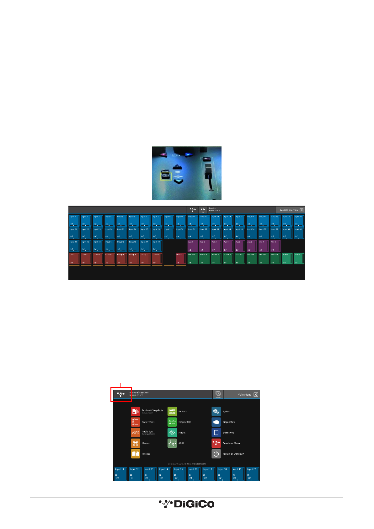
The right hand Master Screen has a DiGiCo logo icon at the top which is used to access the Main Menu.
Main Menu
Page 9
DiGiCo S-Series User Guide – Issue J 1.2 Before You Start
4
1.2.4 The Selected Channel
One of the channels in the Channel view is displayed with a highlighted background, indicating that it is currently the Selected Channel.
This means that it has been assigned to the worksurface controls to the right of the screen as shown in the image below. To assign a
channel, touch in the Output Block at the bottom of the onscreen Channel view.
NOTE: All of the master and under screen rotaries are encoders and switches in one unit.
Often, different functions can be accessed by a standard turn, a push turn and a push (switch).
e.g. Standard turn = Gain control & Push turn = Trim control
NOTE: When the right hand screen is not displaying the Channel view (e.g. it is displaying an EQ view), the master
screen worksurface rotaries will not be assigned to the Channel view controls but to the controls for the EQ or other
expanded view instead.
The block at the top of each Channel Strip displays information about the processing that has been applied to the channel. This box
displays the Gain, Trim and Delay that has been added to the channel. There are also a number of symbols that can be seen along the
Channel Strip which represent settings on the channel.
Their meanings are as follows:
Insert A
Insert B
Listening To Copied Audio
Phantom power
Inverse Input Polarity
Gain tracking
Pad DiGiTube
EQ<>Dyn Swap
Dynamic EQ
The channel is assigned to at least one Group
The channel is a member of at least one Control Group
Assignable Encoder/Switches
Selected Channel
Gain & Trim (Push Turn)
Compressor Threshold
Aux Pan (Stereo)
HPF
Gate Threshold
Aux Level
Output Block area
Touch here to select a channel
Page 10
DiGiCo S-Series User Guide – Issue J 1.2 Before You Start
5
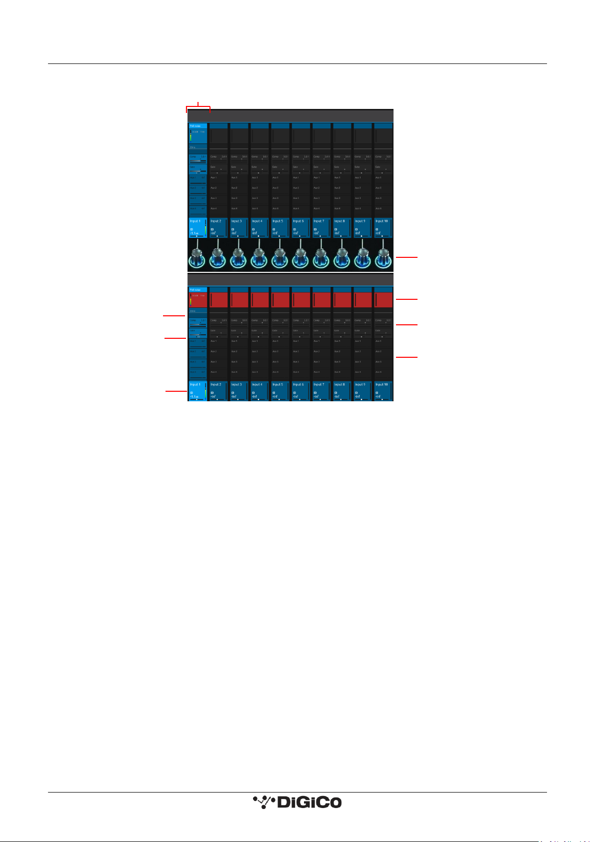
1.2.5 The Under Screen Controls
There is a row of 10 encoder/switches immediately below each touchscreen (shown above) that refer to the channels with which they
are aligned.
These controls give access to the channel pans in standard operation and the surrounding coloured LED rings are blue.
Touching and holding on the rows of controls onscreen assign these encoders to different parameters, the screen row changes colour
and the LED rings change to a similar colour.
In the above example the Gain/Trim row at the top of the Channel View has been touched, the row is highlighted in red and the under
screen controls are assigned to the Gain/Trim function.
Other possible assignments are:
HPF Frequency & On/Off - Row and LED ring highlighted in Mauve
Dynamics 1 Threshold & On/Off - Row and LED ring highlighted in Green
Dynamics 2 Threshold & On/Off - Row and LED ring highlighted in Yellow
Selected Aux row Send level & On/Off - Row and LED ring highlighted in Purple
AMM Weightings - Row and LED ring highlighted in Pale Green
Selected Channel
Blue = Pan - Default assignment
Touch and Hold in this row
Assigns Gain/Trim and highlights in Red
Touch and Hold in this row
Assigns Dynamics 1 Threshold and
On/Off and highlights in Green
Touch and Hold any AUX row
Assigns Aux Send & On/Off
Touch and Hold in this row
Assigns HPF Freq and On/Off
and highlights in Mauve
Touch and Hold in this row
Assigns Dynamics 2 Threshold and On/Off
and highlights in Yellow
Touch the selected channel
in this row to return to
default Pan assignment
Page 11
DiGiCo S-Series User Guide – Issue J 1.3 The Expanded Views
6
1.3 The Expanded Views
1.3.1 Display Expanded Views
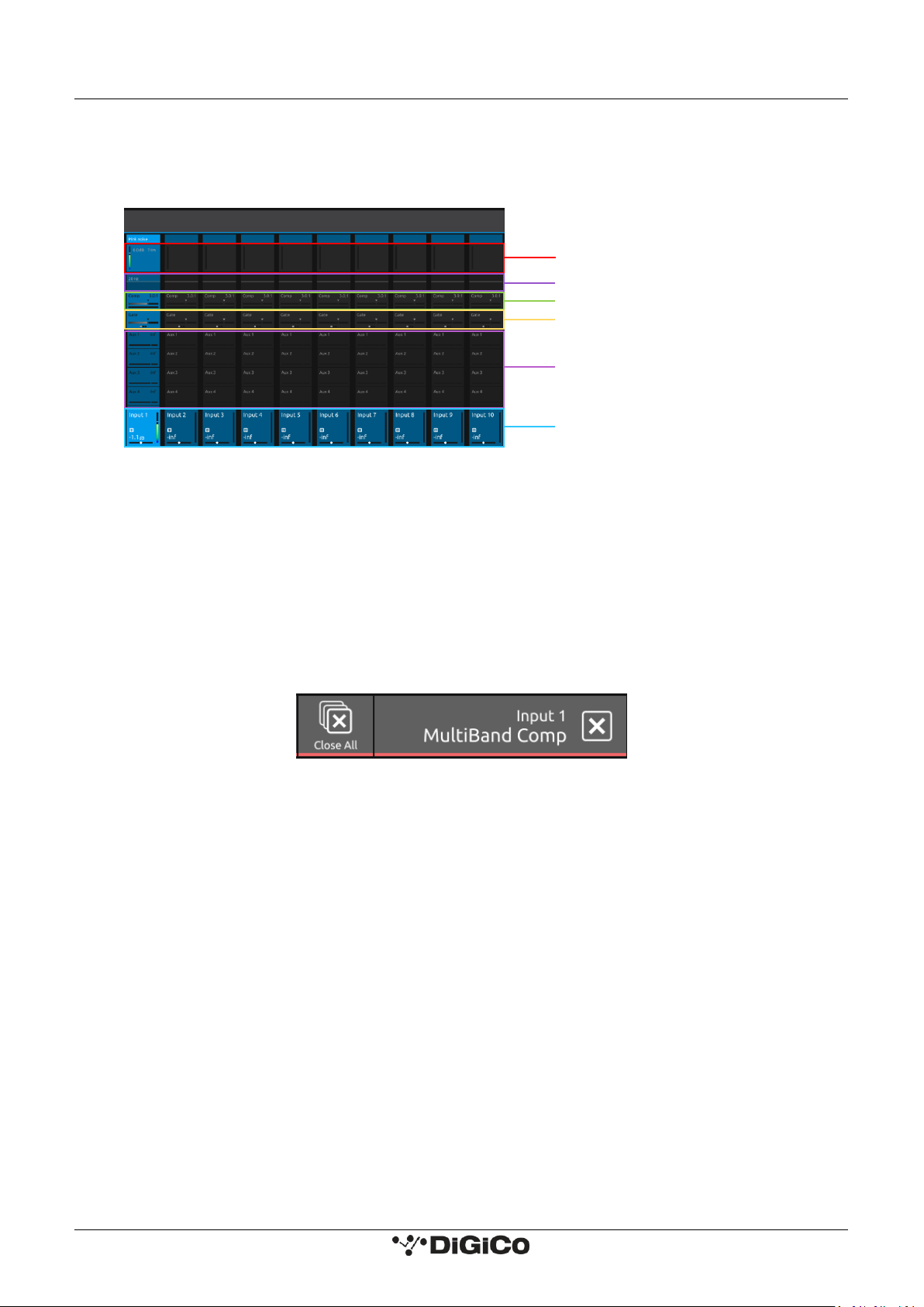
A single touch (rather than a touch and hold) will open a number of different expanded views according to where the touch is made.
The image above shows the various touch areas in the Channel view and the expanded view will be displayed on the Master screen.
NOTE: When an expanded view is already open, selecting a different channel by touching the Output block area at
the bottom of the screen will change the expanded view to display the newly selected channel.
If an expanded view is already open and a different expanded view is selected, the last view selected will be
displayed on the Master screen with the previously expanded view behind it.
Any combination of expanded views can be "layered" in this way.
The Close All button on the Master screen can be touched at any time to close all active expanded views.
The Close button on the Master screen can be touched at any time to close the currently active expanded view and display the view
beneath it.
Open Dynamics 2 View
Touch here to select a channel
Touch any Aux Send to select the channel and assign
the selected Aux Send to the 6th Master Rotary & Aux
Pan to the 5th (with Aux To Faders option OFF)
Swipe vertically to display more Auxes
Open Dynamics 1 View
Open EQ View
Open Channel Setup view
Page 12
DiGiCo S-Series User Guide – Issue J 1.3 The Expanded Views
7
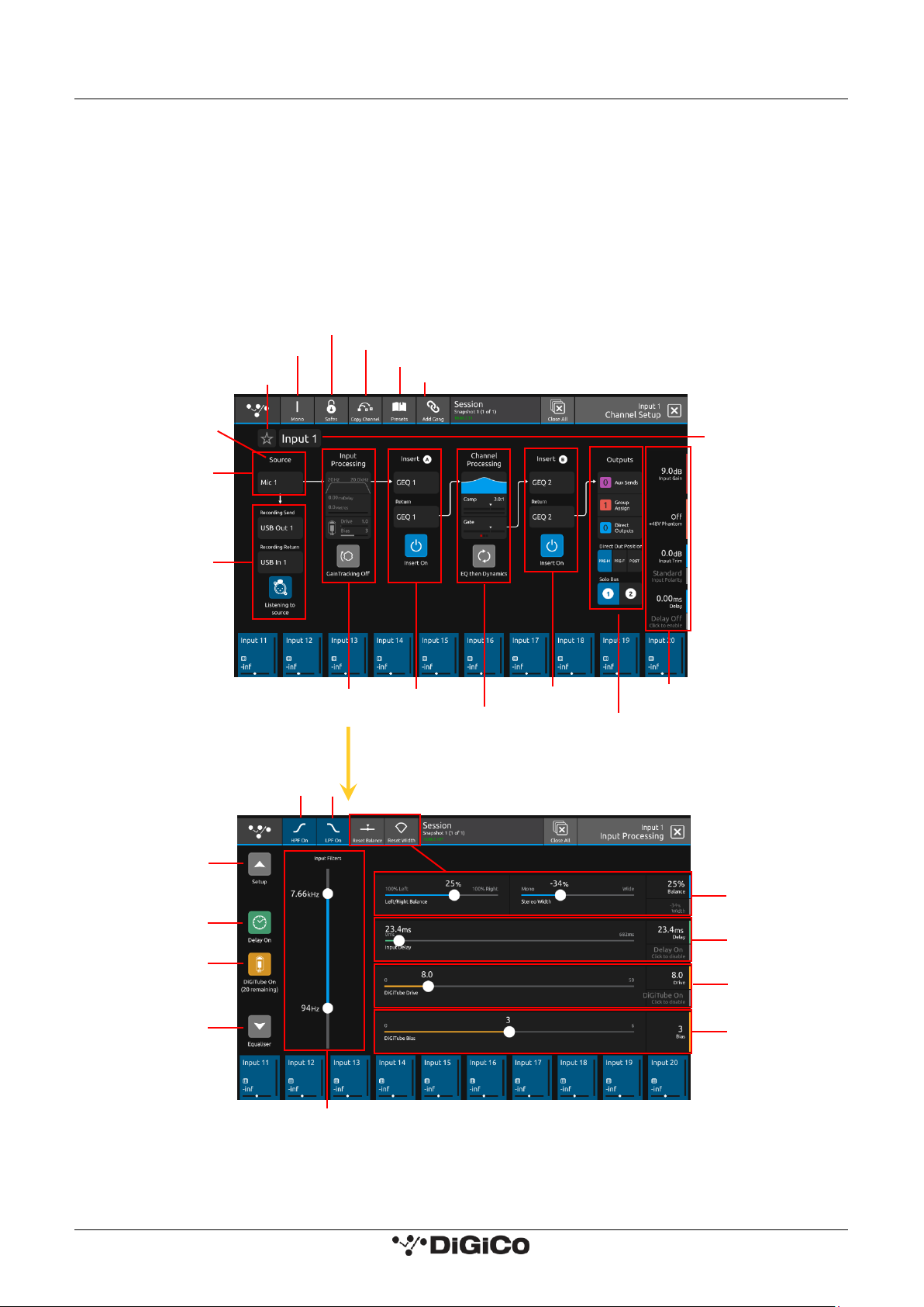
1.3.2 Channel Setup View
Touching the input block at the top of the channel opens the Channel Setup view.
Each column represents a section of the channel processing strip and contains blocks which can be selected by touching them.
On screen arrows indicate the signal path from one section of processing to the next.
Once a block is selected, the display changes accordingly and the parameters available in that section are assigned to the worksurface.
Master Rotaries to the right of the screen.
Note that touching the Filter block or the EQ block will both display the EQ view but with different bands selected.
NOTE: When any expanded view is open on the Master screen, the Master Rotaries no longer have their standard
default assignment and are instead assigned to the parameters in the expanded view which is currently displayed.
Presets
Ganging
Copy Channel Settings
Open Safes View
Channel Mono/Stereo Switch
Add To Spill Set
Column Title
Label
Select Input Source
Recording
Send & Return
Filters/Delay/Tubes
Gain Tracking On/Off
Channel Name
Master Rotary Assignment
Auxes
Groups
Direct Out
Direct Out Position
Select Solo Assignment
Insert B
Insert A
EQ
Dyn 1
Dyn 2
EQ>DYN Swap
HPF On/Off
LPF
Scroll To
Setup View
Delay On/Off
Tube On/Off
Scroll To
EQ View
HPF/LPF Frequency
Stereo Balance
& Width
Delay Time
Tube Drive
Tube Bias
Page 13
DiGiCo S-Series User Guide – Issue J 1.3 The Expanded Views
8
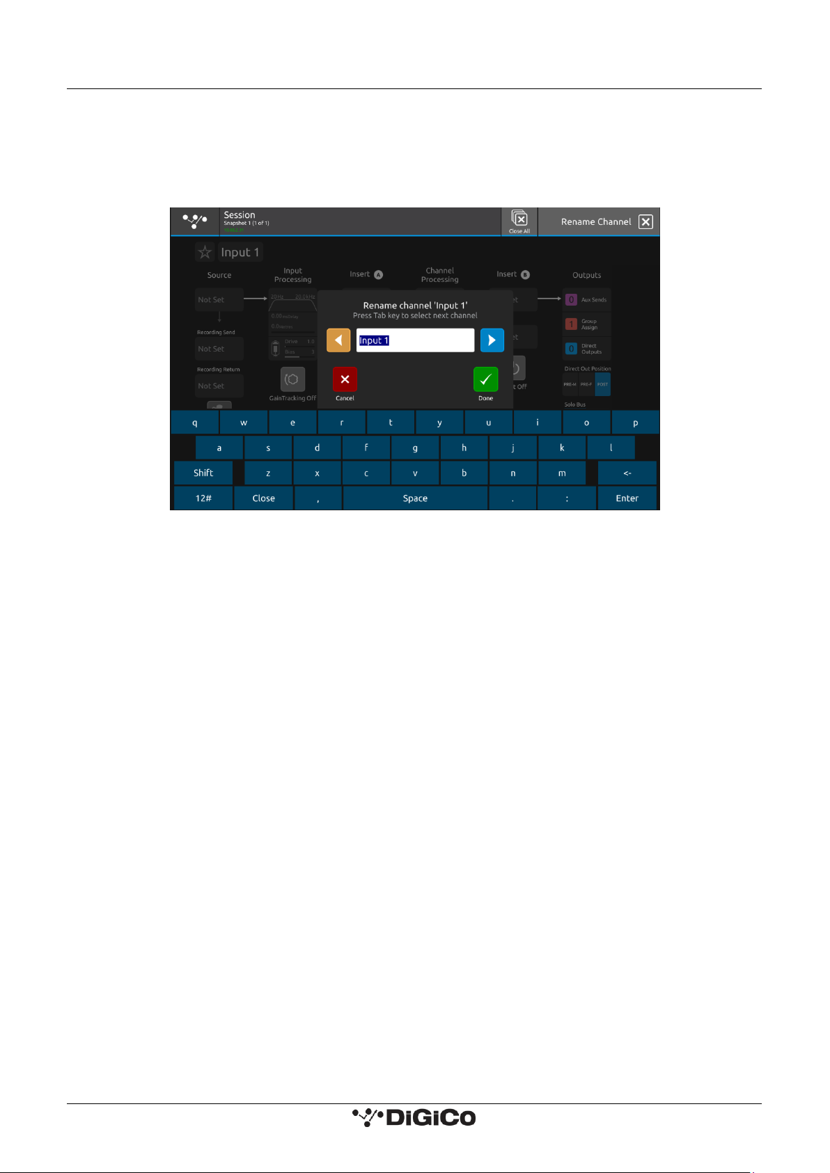
Channel Names can be changed by touching on the existing Channel Name to open the Rename View and then using the Left/Right
scroll buttons to move through channels without closing the Rename View.
Touching the Star icon next to the channel name will add the selected channel to the Spill Set (see Spill Set section later in this document).
The buttons in the top bar provide the following functions:
Switching the channel from Mono to Stereo mode
Opening the Safes View which allows channel parameters to be protected from Snapshot Recall
Opening the Channel Copy view
Opening the Presets view where a preset can either be saved or recalled
Opening the Gang Setup view
Channel Delay, Tube, Filter and Stereo Width/Balance (Stereo Input channels only) settings are adjusted by touching in the Input
Processing column. This will open an Input Processing View.
At the bottom of the input processing column is a switch to turn Gain Tracking On/Off for the channel.
Touch the Equaliser button at the bottom left of the screen to switch to the EQ view for the currently selected channel.
To select an Input Route touch the block below the Source label and the Input routing view will open.
To select an Output Route touch the Direct Output block in the Outputs column and the output routing view will open.
The Direct Out Position can be set to either pre-mute, pre-fader or post-fader.
To assign the channel to a Group buss touch the Group Assigns button in the Outputs column.
To view and adjust Aux Send Options for the channel touch the relevant Aux Sends button in the Outputs column.
To select which Solo Busses the channel is assigned to touch the Solo 1, Solo 2 or both Solo 1&2 buttons at the bottom of the Outputs
column.
The default processing order of EQ > Dynamics can be swapped to Dynamics > EQ independently in any channel using the EQ<>Dyn Swap
button at the bottom of the Channel processing column.
Direct out Position
The direct out send can be sent from one of three positions: pre-mute, pre-fader or post-fader (default) on a per input channel basis.
This does not affect the send position to any buses.
The default send position is post-fader and the selected position is not saved in presets.
The position is included in the direct out section of the channel safe.
NOTE: DiGiTubes are limited to 21 per session.
Page 14
DiGiCo S-Series User Guide – Issue J 1.3 The Expanded Views
9
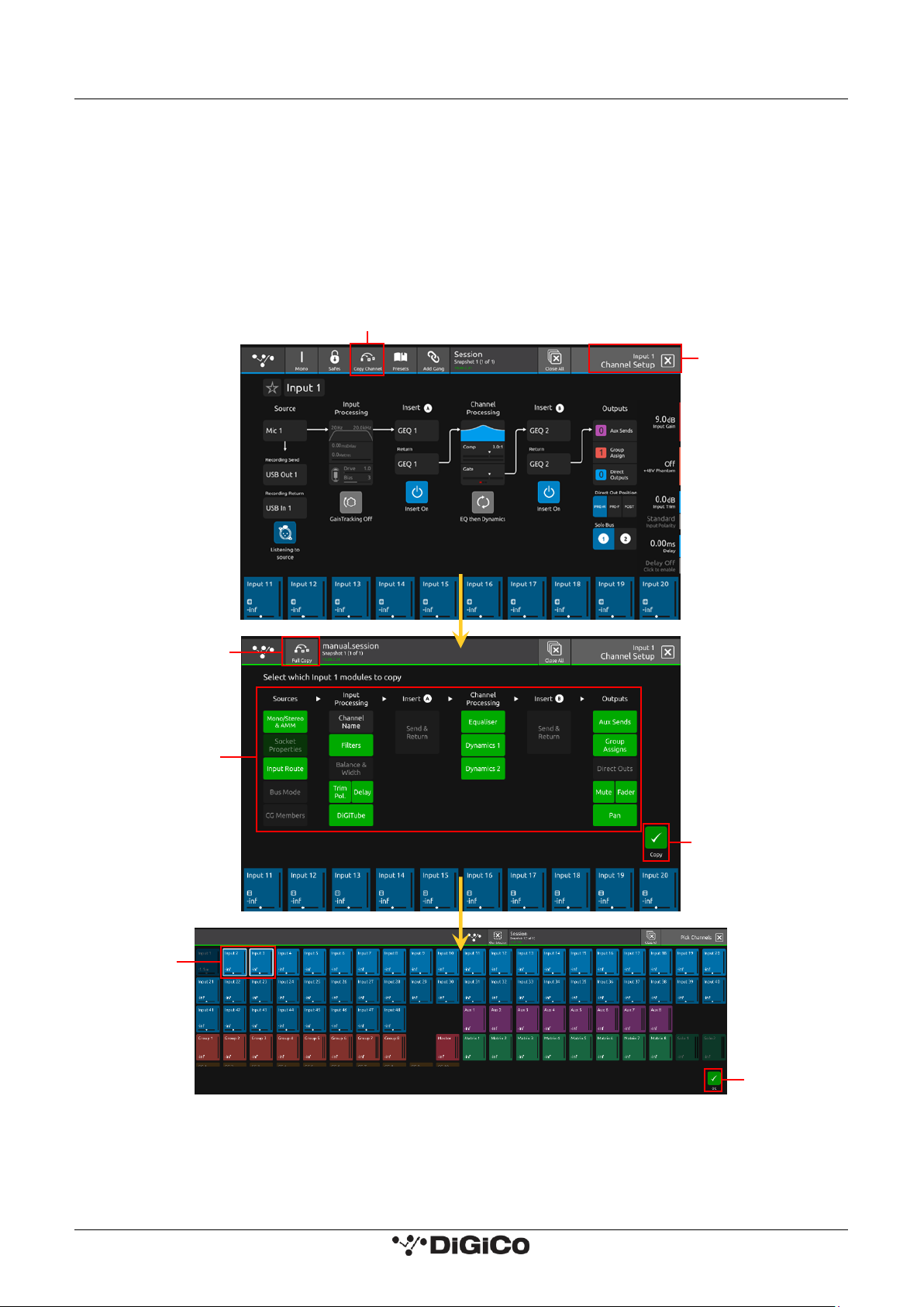
1.3.3 Copy Channel
Multiple settings can be copied from one channel to single or multiple other channels using the Copy Channel button in the Channel
setup view.
Open the Channel Setup view for the required source channel by touching the top of its channel strip.
Touch the Copy Channel button in the top bar.
Touch to select or deselect the parameters that you wish to copy - selected blocks will be highlighted in green.
To select/deselect all of the channel parameters that can be copied touch the Full Copy button in the top bar.
Touch the Copy button in the bottom right of the screen.
Select the Destination channel(s) by touching them on screen - they will have a white outline.
Touch the OK button in the bottom right of the screen.
NOTE: Channel Name is not included in the Full Copy selection but can be selected separately if desired.
NOTE: Insert and Output routes cannot be copied as they could cause conflicts with existing routes.
Not all parameter types exist for all channel types so some options might be unavailable
e.g. Buss mode on an input channel.
Copy Channel Function
Source Channel
Setup View
Full Copy
Option
Green (Selected)
parameters will
be copied
Copy
Button
Select
Destination
Channels
Confirm
Copy
Page 15
DiGiCo S-Series User Guide – Issue J 1.3 The Expanded Views
10
1.3.4 Presets
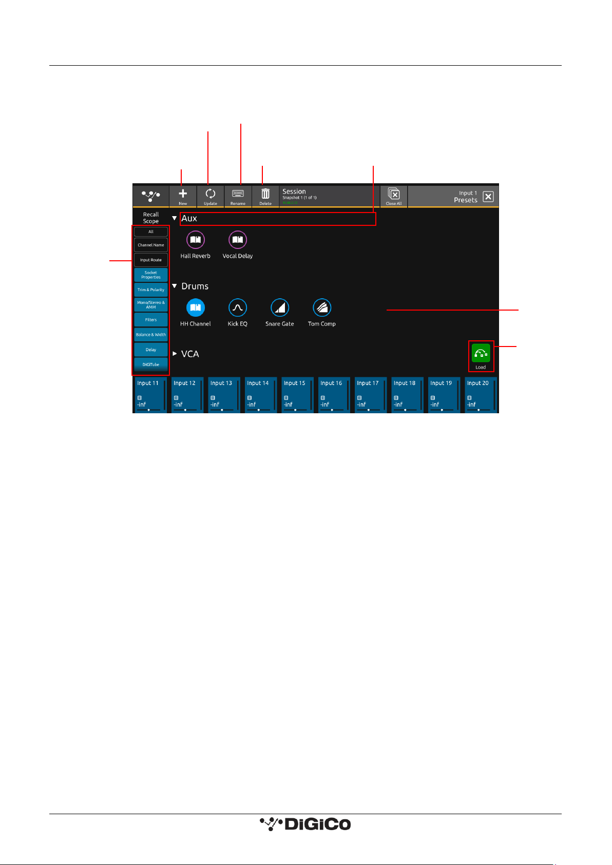
Presets can be used on Input, Group, Aux, Matrix, CG and Master channels. Preset scopes are used to select which parameters are loaded
into the selected channel.
New presets can be made by opening the presets view in the desired channel’s setup, EQ, dynamics 1 or dynamics 2 view. In this view,
press New then enter the preset name and optionally, a group, before confirming. All parameters for that channel are saved into a preset.
The view in which the preset was created will determine the preset icon.
Presets are updated and deleted by selecting one of these functions in the top of the presets view, selecting the presets to be updated
or deleted, then confirming by pressing the Update or Delete confirm at the bottom right of the view. To rename a preset or group,
select Rename then touch on the preset or group which will bring up a rename dialogue.
Create a new
preset
Select the preset to
update
Select the preset(s) to
delete
Load, update
or delete the
selected
preset(s)
Select the group or
preset to rename
Select the
scopes to load
– Socket
Properties
includes gain,
pad, phantom
power and AES
SRC
Press the group name
to expand and collapse
Groups and
presets listed
in alphabetical
order
Page 16
DiGiCo S-Series User Guide – Issue J 1.3 The Expanded Views
11
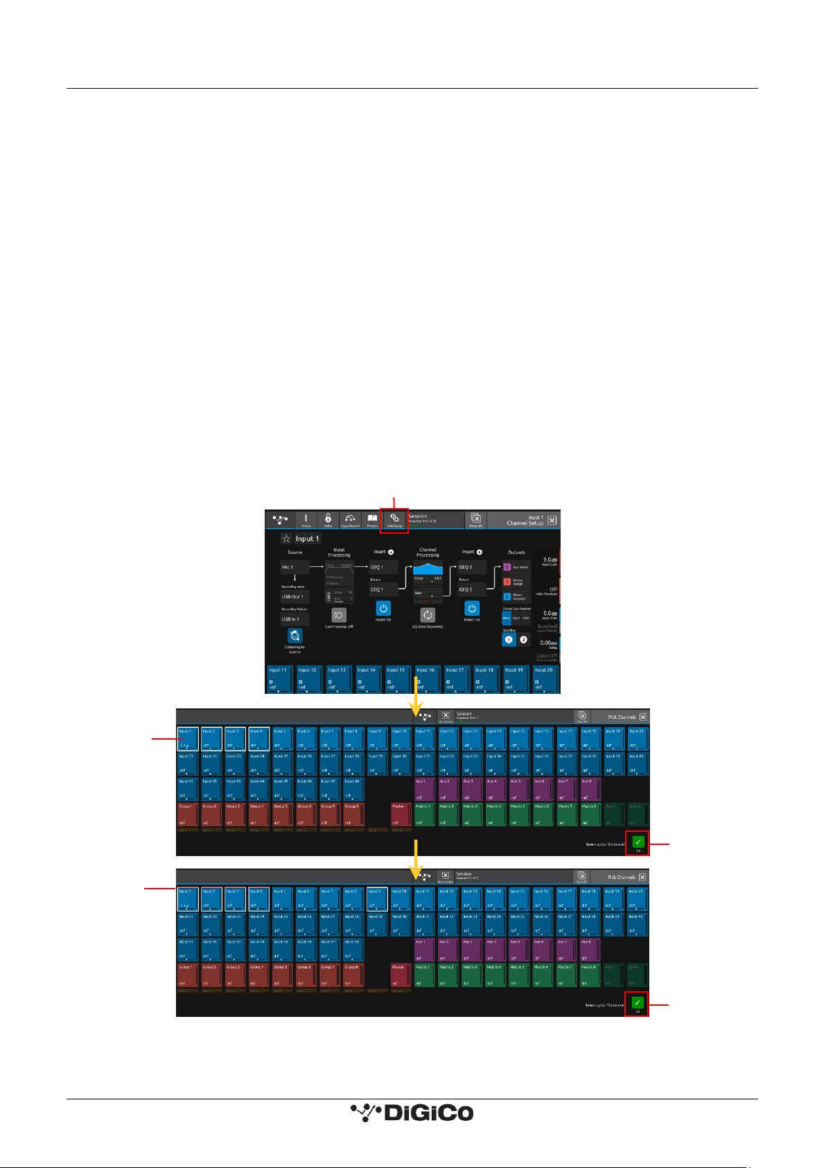
1.3.5 Channel Ganging
Any channel can be ganged (linked) to one or more other channels (up to a maximum of 10 channels) so that changes made on one will
also be made to other members of the gang. This excludes Control Group and Solo channel types.
All level parameters that are measured in dBs (e.g. faders) will change relatively so moving a fader on one member of the gang by +3dB
will add +3dB to all other members of the gang irrespective of their starting point.
NOTE: Channel Ganging is limited to a selection of up to 10 channels from anywhere on the console.
Multiple gangs can be created but a single channel can only be in one gang at one time.
To create a new gang:
Select the first required member channel of the new gang in the Channel view.
Touch the top of that channel to open the Channel Setup View.
Touch the Add Gang button in the top bar of the Channel Setup View.
Touch the relevant channel blocks in the Pick Channels View to select or deselect members.
Touch the OK button to confirm.
Members will now be displayed with a colour coded line at top of the output block on each gang member.
To edit an existing gang:
Select any member channel of the existing gang in the Channel view.
Touch the top of that channel to open the Channel Setup view.
Touch the Edit Gang button in the top bar of the Channel Setup View.
Touch the relevant channel blocks in the Pick Channels View to select or deselect members.
Touch the OK button to confirm.
Add/Edit Gang
Touch to
select
members
Colour coded
members
Touch to remove
or select new
members
OK to
Confirm
OK to
Confirm
Page 17

DiGiCo S-Series User Guide – Issue J 1.3 The Expanded Views
12
Parameters that are included in gangs are a fixed selection of most standard channel functions, but the following elements are among
the parameters that are not included:
Routing Input/Output/Insert/Record Send & Return
Mono/Stereo switch
Polarity switch
Analogue socket gain
+48V
Channel & Aux Panning
Parameter Safe Status
CG Membership
Bus Mode
Fader Crossfades
AMM Membership
AMM Weighting
NOTE: Gang membership cannot be changed with snapshots.
NOTE: Gang members cannot be temporarily isolated from a gang - to change the settings in just one channel, first
remove it from the gang, make the changes and then add it back to the gang again.
NOTE: If any element of a gang member is "Flattened" this change will only apply that that member and not to any
of the other members of the gang.
Also if settings are copied to any member of a gang, the new settings will only be applied to that member of the
gang and not to any of the other members of the gang.
Page 18
DiGiCo S-Series User Guide – Issue J 1.3 The Expanded Views
13
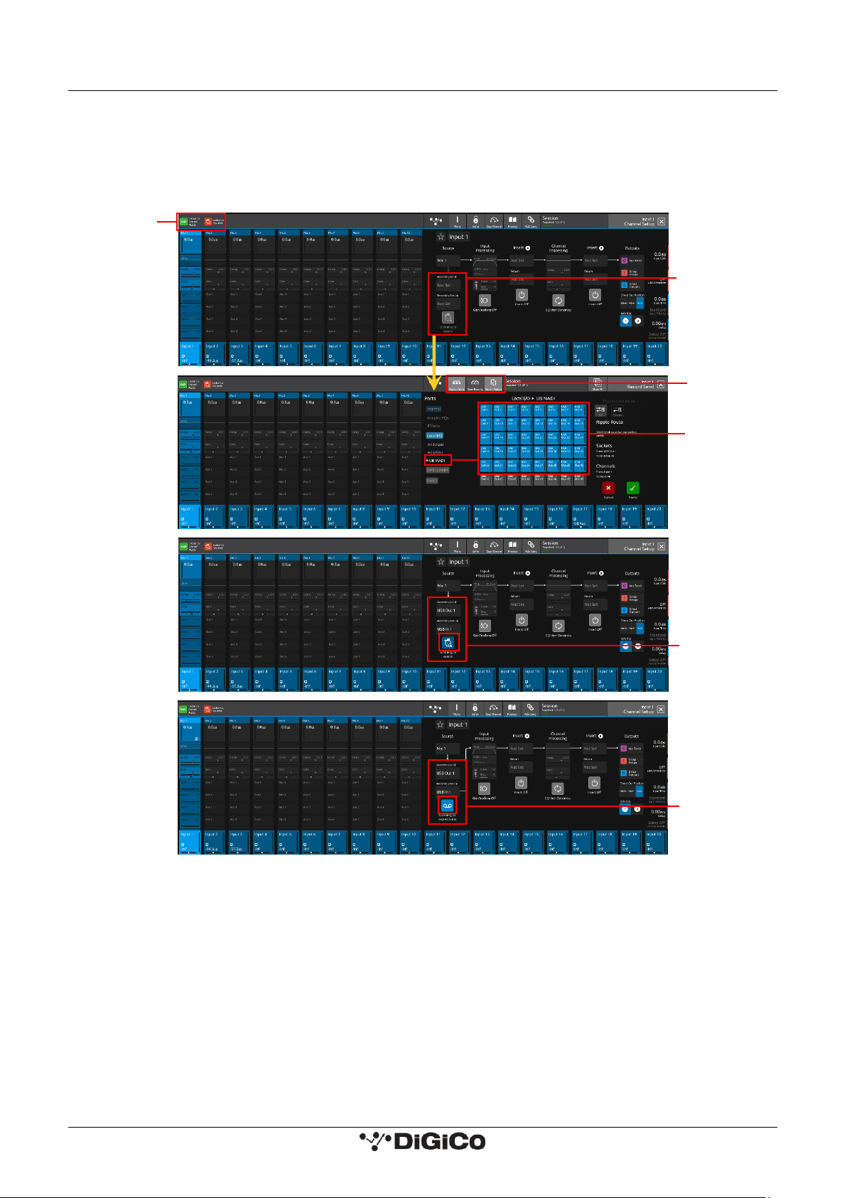
1.3.6 Recording & Virtual Soundcheck
Any input channel can be sent from a dedicated pre-processing Record Send point in the channel signal path to any valid output socket.
Typically a selection of input channel signals would be sent to the console's UB MADI interface for recording on a DAW via a USB
connection.
Playback signals from the DAW can then be returned into the dedicated Record Return and switched either individually or globally to
replace the standard input signal to that channel. This is known as Listening to Copied Audio.
To set up a Record Send and Return:
1) Touch the top of the first input channel that you wish to record to open the Channel Setup View
2) Touch the Recording Send button on the left of the screen to display the Record Send Routing view
3) Ensure that the Send+Return mode is active using the button in the top bar
4) Select an output to feed the recorder by first selecting a port (e.g. UB MADI) and then a socket from that port (e.g. USB OUT 1) Multiple
channel Record Sends can be assigned at the same time using the standard Ripple Route function
5) When the Record Send selections have been made, touch the Route button at the bottom right of the screen to confirm.
6) Select the Channel Setup View again and you will note that the relevant, same numbered input route for the Record Return has
automatically been assigned. So if your Record Send was USB Out 1 then your Record Return will be USB In 1
7) The button below the Record Send & Return has 2 states:
a) Listening to Source - the Record signal is being sent and the channel signal is the original Record Send source
b) Listening to Copied Audio - The Record signal is being sent and the channel signal is the Record Return from the recording device e.g.
Playback signal
Listen to Sources
&
Listen to Copied Audio
Macros
Record Send and
Return Routing
Ripple Route with
Send+Return
Active
Record Sends to
40 x UB MADI
Outputs
Listening To
Source
Listening To
Copied Audio
Page 19
DiGiCo S-Series User Guide – Issue J 1.3 The Expanded Views
14
NOTE: There are 2 Macros available that allow switching of all console Record Sends from Listen to Sources to
Listen to Copied Audio. Using these 2 Macros, the console can be set to monitor record source or record returns
globally for all channels that are being recorded.
Record Sends and Returns do not have to use the console UB MADI Port, they can use any port or combination of ports in any socket
order required. For example, a recording could be made via a DMI-MADI card.
A Record Send can be routed to multiple destinations at the same time, but a Record Return can only be fed from one input socket at
one time. This is the input socket that will be used when Listen To Copied Audio is active.
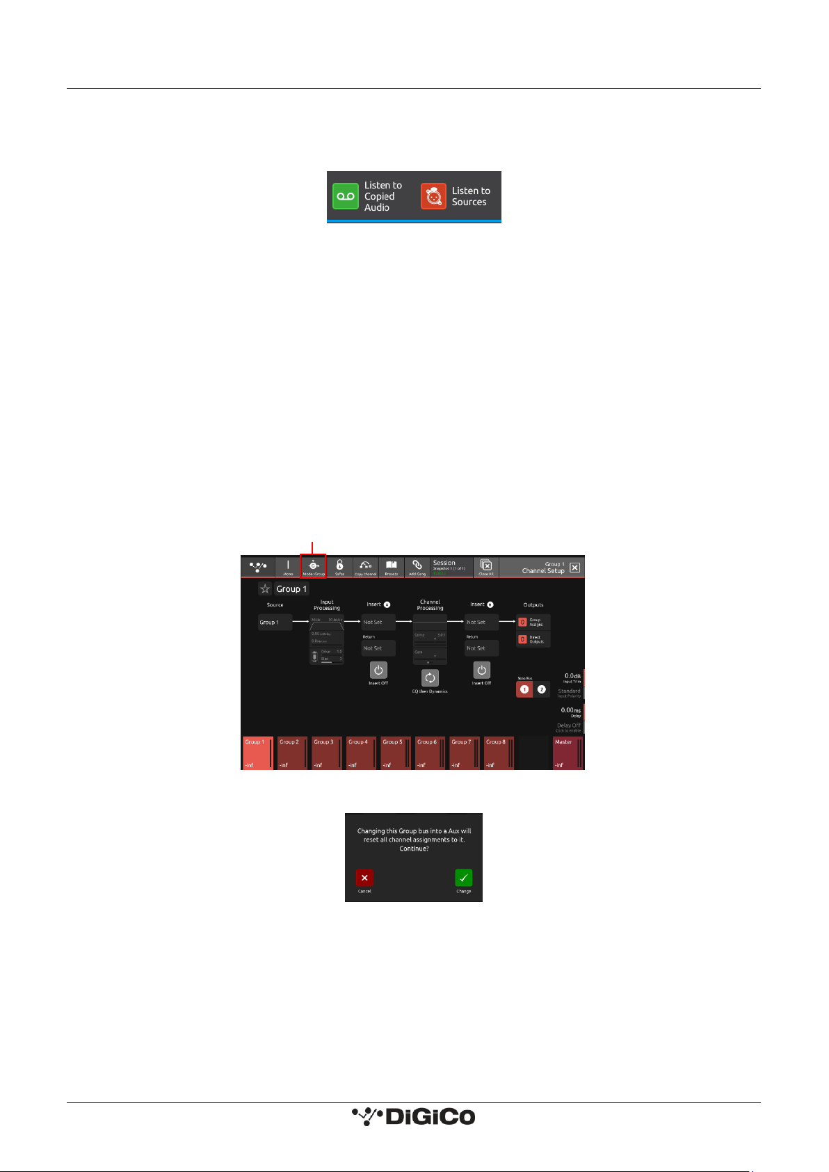
1.3.7 Group and Aux Setup View
The Group and Aux Channel Setup view are very similar to the Input Channel version, but they have one extra function that is used to
convert a Group Buss to an Aux Buss or vice versa.
The S-Series consoles have a fixed number of output busses, but they can be changed at any time to be either Auxes or Groups.
In the example below, touching the Mode button on the Group Setup view will change the Group to an Aux but there is warning that all
channel assignments will be reset in the process. So the newly converted Aux will be flattened.
The situation is exactly the same when converting an Aux to a Group - all assignments are reset.
NOTE: In Aux/Group Buss Mode can be changed with a Snapshot recall which has its own Safe block. Please ensure
that the buss modes are set in your first Snapshot before you create any further Snapshots. This will ensure that
the buss mode settings will be consistent in all Snapshots.
Warning
Change Group to Aux
Page 20

DiGiCo S-Series User Guide – Issue J 1.3 The Expanded Views
15
Group To Group Routing
Any mono or stereo Group buss can be assigned to any other buss (including the Master buss) using the Group Assigns view on a Group
channel.
Touch the top of a Group channel to open the Channel Setup view, touch the Group Assigns button in the Outputs column.
In the example below, Group 1 is assigned to the Master buss by touching the Master buss button.
NOTE: A Group cannot be assigned to itself
Aux Send Pre/Post Switches
Any Aux buss can have all of its related sends from all channels set to Pre/Pre-Mute/Post using the buttons in the Aux buss setup view.
Touch the top of an Aux channel to open the Channel Setup view and then touch the relevant Set All Sends To button on the right of the
screen. A warning will be displayed which can be confirmed by touching the Yes button.
Group 1 to
Master Buss
Group Assigns
Select Mode for
all Aux 1 Sends
Page 21
DiGiCo S-Series User Guide – Issue J 1.3 The Expanded Views
16
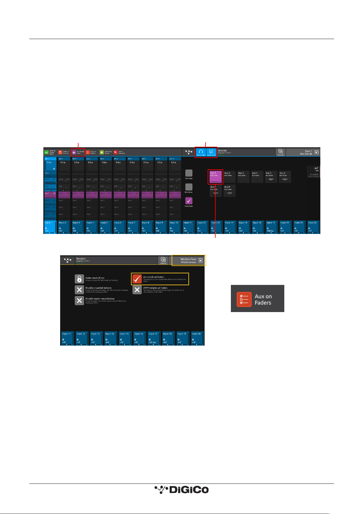
1.3.8 Aux Sends View
The Aux Sends View panel displays every aux buss in the current session and touching the buss will activate the buss solo and aux to
faders.
It can be accessed from any input channel's setup view by selecting the outputs column and touching the Aux Sends button in the Outputs
column or from the Aux Sends View Macro.
There are 2 options in the top bar:
1) Solo on select - with this option active, the relevant Aux Master Solo will be activated
2) Assign on select - with this option active, the relevant Aux buss sends will be assigned to either the input channel faders or the
underscreen rotaries according to the status of the Aux To Faders option in the Worksurface Preferences panel (found in the Preferences
Panel)
If Aux To Faders is OFF the sends are assigned to the underscreen rotaries.
If Aux To Faders is ON the sends are assigned to the channel faders.
OR
Aux to Faders On/Off
Macro
Select Aux Buss
Assign & Solo On Select Options
Aux Sends View Macro
Page 22
DiGiCo S-Series User Guide – Issue J 1.3 The Expanded Views
17
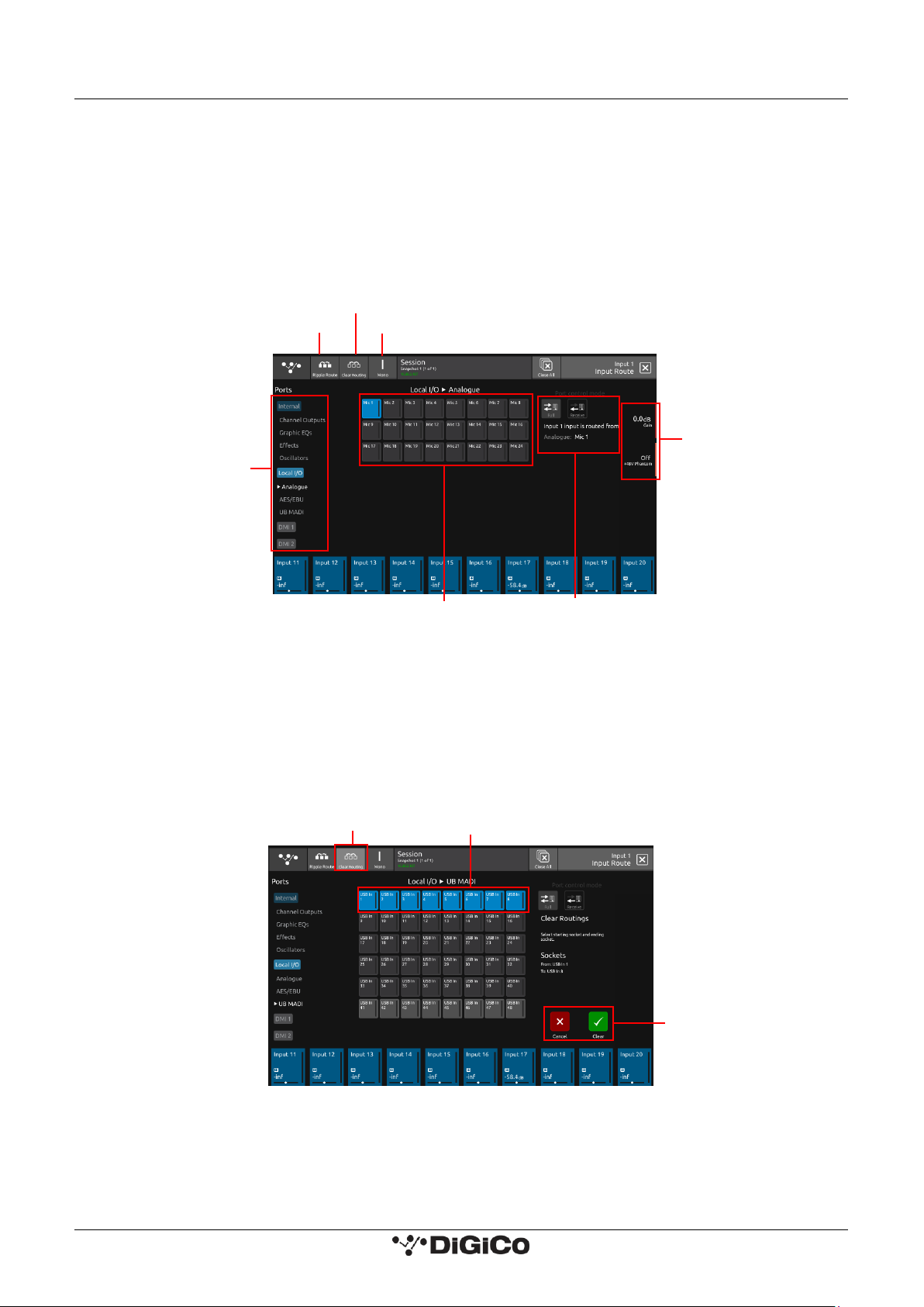
1.3.9 Input Routing View
Touching the Source area on the Channel Setup will open the Input Route expanded view.
Only input channels have a Source selection - output channels sources are fixed within the system.
To select an input source, touch one of the buttons in the port list on the left of the screen and the relevant sockets will be displayed.
Now touch to select a socket in the socket display.
Inputs can be routed into multiple channels at the same time using the Ripple Route function.
Touch the Ripple Route button in the top bar and then select the first and last sockets in the required range - then press the OK button.
The Master Rotaries are assigned to the Gain/Trim, +48V and Input Pad controls if they exist for the socket type selected.
NOTE: Ripple routes are automatically done in the channel display order rather than channel number order.
Clear Routing
Multiple consecutive socket routes (inputs or outputs) can be cleared using the Clear Routing function.
From any input or output routing view, select the relevant port by touching the port name in the left hand column.
Touch the Clear Routing button in the top bar.
Select the first and last sockets in the range that you wish to clear.
Touch the Clear button at the bottom right of the panel.
In the example below UB MADI Port - Input Sockets 1-8 will be cleared.
NOTE: Sockets routings are cleared in socket order, not in channel order, so in the above example, the sockets that
are cleared may not necessarily belong to adjacent channels. The input routing will be cleared from ANY channel
that has these sockets as an input source. This is not a channel Clear Routing function but rather a socket Clear
Routing function.
Ripple Route
Channel Mono/Stereo switch
Clear Routing
Routing
Details
Select Socket
Select Port
and
Socket Type
Master Rotary
Assignment
Select first and last sockets to clear
Clear Routing
Mode
Clear or Cancel
Page 23
DiGiCo S-Series User Guide – Issue J 1.3 The Expanded Views
18
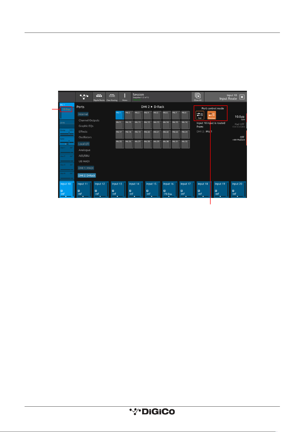
Receive Only Mode
Ports have two different control modes. Receive Only Mode prevents the console from changing Gain, Phantom Power and Pad values.
Full Control Mode allows the console to change these values.
To change the Port Control Mode, in the Input routing view, touch the desired mode to the right of the view.
This can also be done in the Output routing view.
When in Receive Only Mode, Gain values will appear in Orange text on the Channel Strip.
NOTE: This Port Control Mode is controlled on a per rack basis and cannot be changed with snapshots.
Orange Gain
text
Port Control Mode
Page 24

DiGiCo S-Series User Guide – Issue J 1.3 The Expanded Views
19
1.3.10 EQ View
Touching the EQ area on either the Channel view or the Channel Setup will open the EQ expanded view.
The EQ band can be selected by touching the band icons on the left of the screen or by touching the bands on the EQ graph itself.
The graph has 2 modes, 4 band EQ or filters. Touch the relevant band and the adjust the parameters by dragging the band icon on the
graph.
While an EQ band is selected, it can be "pinched" on screen to adjust the Q setting.
The selected band's parameters can also be adjusted with the Master Rotaries to the right of the screen.
The buttons in the top bar provide the following functions:
EQ On/Off
Show Dynamic EQ controls
Copy EQ to another channel(s) - touch the button and select the destination channels from the channel picker - OK to confirm
Presets can be saved or recalled from this view. The recall scope only included EQ when recalling a preset from the EQ view.
Flatten EQ
Presets
Master
Rotary
Assignment
Select Filters
Drag to adjust
Select EQ Band
Drag to adjust
Select EQ Band
EQ On/Off
Show Dyn EQ
Copy EQ
Flatten EQ
Switch to Channel Setup
Switch to Dyn 1 View
Page 25

DiGiCo S-Series User Guide – Issue J 1.3 The Expanded Views
20
Dynamic EQ
Touching the Show Dyn EQ button at the top of a channel’s EQ view opens the Dynamic EQ View.
Touching it again will hide the Dynamic EQ controls.
Each EQ band can be turned into a Dynamic EQ band by touching the Dyn EQ On/Off button at the left of the screen for each band. Bands
where Dynamic EQ is active will be shown with the Dynamic EQ symbol in the Band Icon. The corresponding dynamics icon of each band
will appear as a solid colour when active.
The parameters of each Dynamic EQ band can be adjusted by dragging the sliders at the bottom of the view or touching a band and using
the Master Rotaries.
Each Dynamic EQ band has 2 modes. In Over Mode, the EQ adjustment is applied when the level of the incoming signal is over the
threshold. Under Mode applies the EQ adjustment when the incoming signal is below the threshold. The mode can be changed by
selecting the band and using the Master Rotaries. The mode is shown by the direction of the arrow next to the Threshold slider at the
bottom of the view.
Next to the slider controls of each band is a Bipolar Meter. The level of the meter will rise when the band is being boosted and fall when
the band is being attenuated.
NOTE: Dynamic EQ is limited to 21 per session.
Dyn EQ On/Off
for each band
Bipolar meters
Master
Rotary
Assignment
Threshold slider icons
indicate Mode
Adjust
Parameters
for each band
Band Icons
Dynamic EQ
indication
Page 26

DiGiCo S-Series User Guide – Issue J 1.3 The Expanded Views
21
Switch to Dyn 2 view
Adjust
Parameters
Master Rotary
Assignment
Switch to EQ view
Reset Dyn 1
Copy Dyn 1
Select Mode
Dyn 1 On/Off
1.3.11 Dynamics 1 View
Touching the Dynamics 1 area on either the Channel view or the Channel Setup will open the Dynamics 1 expanded view.
Dynamics 1 can be a Single Band or Multiband Compressor (on 21 channels). Touch the Mode button in the top bar to switch modes.
Multiband Dynamics has 4 viewing modes, one for each individual band and one that displays all 3 bands at the same time. These are
selected with the buttons on the left of the screen.
Parameters can be adjusted on-screen or using the Master Rotaries to the right of the screen.
The buttons in the top bar also provide the following functions:
Dynamics Module On/Off
Copy Dynamics settings to another channel(s) - touch the button and select the destination channels from the channel picker - OK to
confirm
Reset Dynamics module
NOTE: Multiband Compressors are limited to 21 per session.
Presets
Presets
Presets
Switch to Dyn 2 view
Adjust
Parameters
Master Rotary
Assignment
Switch to EQ view
Reset Dyn 1
Copy Dyn 1
Select Mode
Dyn 1 On/Off
Switch to Dyn 2 view
Adjust
Parameters
Master Rotary
Assignment
Switch to EQ view
Reset Dyn 1
Copy Dyn 1
Select Mode
Dyn 1 On/Off
Page 27

DiGiCo S-Series User Guide – Issue J 1.3 The Expanded Views
22
1.3.12 Dynamics 2 View
Touching the Dynamics 2 area on either the Channel view or the Channel Setup will open the Dynamics 2 expanded view.
Dynamics 2 can be a Keyed Gate, a Ducker or Single Band Compressor with Side Chain.
Touch the Mode button in the top bar to switch modes.
Dynamics module 2 provides side chain access via a selectable input - this can be used for external triggering.
Select the Source signal by touching the Key/Side Chain input button on the left of the screen and select a source from the standard
input routing list. Then use the Self/Ext button to activate this function.
Parameters can be adjusted on-screen or using the Master Rotaries to the right of the screen.
The buttons in the top bar also provide the following functions:
Dynamics Module On/Off
Copy Dynamics settings to another channel(s) - touch the button and select the destination channels from the channel picker - OK to
confirm
Reset Dynamics module
Presets
Key Input On/Off
Adjust
Parameters
Master Rotary
Assignment
Switch to Dyn 1 view
Reset Dyn 2
Copy Dyn 2
Select Mode
Dyn 2 On/Off
Select Key Source
Gate status
Meter and Key Filter
Select Mode
Select Dyn 2 Mode
Page 28

DiGiCo S-Series User Guide – Issue J 1.3 The Expanded Views
23
1.3.13 Control Group Setup
To create a Control Group, touch the top of a Control Group Channel to open the CG Setup view.
Touch the Edit button in the top bar and then touch the Members button from the drop down menu.
Select the required CG members by touching them in the Channel Picker and touch the OK button.
The CG members can also be changed by double tapping on the centre section of the Control Group Channel.
The CG Setup view will now show blocks representing each of the CG members and the CG channel will display a list of its members with
their fader levels.
Control Group Spill
Up to 10 members of a Control Group can be spilled onto a preselected screen.
Touch the Edit button in the top bar and then touch the Spill Selection button from the drop down menu.
Select the channels to add to the CG Spill by touching them. Channels in the Control Group Spill are shown with an orange outline. The
order of channels can also be changed by dragging the Channel boxes.
Touching the Edit button again will exit Edit mode.
The Control Group Spill Screen can be changed in the Preferences menu.
A Control Group can be spilled in 4 different ways:
Touching the Spill Members button at the top of the CG Channel Setup view.
Holding the centre section of the Control Group Channel.
A Spill Macro exists for each Control Group.
Touch to select members
OK to
Confirm
Setup CG
Edit CG Members
Page 29

DiGiCo S-Series User Guide – Issue J 1.3 The Expanded Views
24
The Solo button of the Control Group can be repurposed in the Solo Preferences menu to open the Spill.
A Control Group Spill can be closed in 4 different ways:
Touching the Close Spill button at the top of the Master screen.
Holding the centre section of the Control Group Channel.
Touching the Close Spill Macro (the Spill Macro will change to a Close Spill macro when the spill is open).
Unsoloing the Control Group (if the Control Group Solo button was used to open the spill).
Edit Spill Selection
Close Control Group Spill
Macro
Close Spill button
Spill Control Group Macro
Hold centre
section of
channel to
spill
Spill Members button
Light grey button to show
Edit mode is active
Orange borders
to show Spill
channels
Page 30

DiGiCo S-Series User Guide – Issue J 1.3 The Expanded Views
25
Control Group Modes
Control Groups have 2 modes, VCA and Mute Group - any CG can be switched to either of these modes.
In VCA Mode, the CG fader and mute will both affect the CG member channels.
In Mute Group Mode, the CG Mute will affect the CG member channels, but the CG fader will have no effect on the member channels.
Macros are provided to adjust CG mutes from the Macro Bar.
To switch CG Mode:
Touch the top of a CG channel to open the CG setup view.
Touch the Mode button in the top bar to switch modes.
NOTE: In Mute Group Mode, if the CG fader is moved, it will return automatically to 0dB.
NOTE: If a CG is switched from VCA Mode to Mute Mode, the faders will be reset to 0dB - an on screen warning will
be displayed to indicate that this is going to happen.
Mute
Group
Mode
CG Mode
Default = VCA
Touch here to switch to
Mute Mode
Faders will be
set to 0dB
on switch
CG Spill
Macros
CG Mute
Macros
Page 31

DiGiCo S-Series User Guide – Issue J 1.3 The Expanded Views
26
1.3.14 Solo Channel Setup
The S-Series consoles have 2 Solo busses which have their own control channels in the console layout normally located on the 4th layer
next to the Matrix Output channels.
NOTE: Both Solo busses 1&2 are both sent permanently to the console headphone socket. When no channels are
soloed, the Master Buss (No Solo source) will always be sent to Solo Buss 1
Touching the top of either Solo channel will open the relevant Solo setup view.
Various Solo buss settings can be found in the top bar of this view.
Solo busses can be switched Mono or Stereo.
They can be set to PFL or AFL mode.
They can be set to Multi Mode where multiple solos can be switched on at the same time or Single Mode where switching one solo on
will cancel previously active Solos.
Any channel can be assigned to Solo Buss 1, 2 or both 1&2.
Open the channel setup view for any channel and there are Solo Buss Assignment buttons at the bottom of the output column.
Stereo Mono
Switch
PFL/AFL
Mode
Multi/Single
Mode
Route Solo
Direct Out
Solo
Channels
Page 32

DiGiCo S-Series User Guide – Issue J 1.4 Customising the Layout
27
1.4 Customising the Layout
1.4.1 The Console Overview
Pressing the white Overview button, located near the layer up and down buttons displays an on screen representation of all console
channels. This view can be used to change the layout of the console channels and banks.
Touching the Edit button in the top bar changes the appearance of the display and activates drag and drop capability.
Any block that represents a channel can be dragged to another position and dropped there. This will overwrite the channel in that position
and the overwritten channel will reappear in the Unassigned Channels section at the bottom of the left screen.
Channel blocks can also be dragged directly to the Unassigned Channels section to remove them from the worksurface.
NOTE: Channel blocks can be dragged between the console screens.
1.4.2 The Spill Set
In Edit mode, a selection of up to 10 channels can be dragged to the Spill Set section at the bottom of the right hand overview screen to
create a Spill Set.
Typically, these would be channels to which the user needs to have quick access at all times.
When a Spill Set has been created, the worksurface button located above the overview button will become blue and pressing this button
will display the Spill Set channels on the right hand screen. pressing again hides the Spill Set.
Page 33

DiGiCo S-Series User Guide – Issue J 1.4 Customising the Layout
28
1.4.3 Swap Banks
In Edit mode, touching the Edit Banks and then the Swap Banks button in the top bar allows complete banks to be moved from one
position to another either from left to right or from one layer to another.
1.4.4 Set Master
In Edit mode, touching the Set Master button in the top bar allows a bank to be selected that will be locked to the right hand console
screen. Touch the Set Master button and then touch the required bank.
In this mode, all other banks are assigned to the left hand console screen and can be accessed using the worksurface layer up and down
buttons. Once a Master is set, it can be cleared by touching the Clear Master button in the top bar.
Swap Banks
Set Master / Clear Master
Page 34

DiGiCo S-Series User Guide – Issue J 1.4 Customising the Layout
29
1.4.5 Add/Delete Banks
In Edit mode, touching the Edit Banks button, displays the Add Bank button and when touched, this button will add an empty bank to
the existing layout. The console can have up to 12 banks on 6 layers (S21) or 4 layers (S31) when the console is not in Master Mode.
To remove existing banks, select the bank by touching it in the overview display and a Remove Banks button will be displayed in the top
bar. Touch this button and a warning be will be displayed that requires a user confirmation. When this message is confirmed, the contents
of the bank that has been removed will appear in the Unassigned Channels section of the display.
Add Bank
Remove Banks
Select Bank
Confirm
Channels
Unassigned
Page 35

DiGiCo S-Series User Guide – Issue J 1.5 The Main Menu
30
1.5 The Main Menu
The right hand Master Screen has a DiGiCo logo icon at the top which is used to open the Main Menu.
The Main Menu contains a number of buttons which are used to access various console functions.
1.5.1 Session Management
Touching the Sessions & Snapshots button opens a display which contains file management functions in the top bar and Snapshot control
in the main area of the screen.
Create New Session
Save Session
Save As New File
Load Session
File Drop Down
Menu
Global Scope
Session Name
Snapshot has
unsaved changes
Update Multiple Snapshots
Current Snapshot - Red
Undo Snapshot Recall
Redo Snapshot Recall
Selected Snapshot - Grey
Edit Mode
Snapshot Name
Snapshot Auto Update
Fader Crossfades
Insert New Snapshots
Update
Snapshot
Fire Button
Page 36

DiGiCo S-Series User Guide – Issue J 1.5 The Main Menu
31
NOTE: The Auto-Update button on the left of the screen relates to Snapshots and not to Sessions.
When active, this function will automatically update the current Snapshot as changes are made on the console.
Please read the Snapshot section and only activate this function if you definitely require it.
To create a new session, touch the New button in the top bar and an activity indicator will be displayed.
When the process is complete, touch the Save As button, select the internal drive (labelled Internal) or the USB port (with a USB key
inserted into the console USB port) and touch the Save Here button.
Then type a new session name using the on-screen keyboard and touch the Done button.
To update the session after the initial Save As process, just touch the Save button and the current session will be updated automatically.
To load an existing session, touch the Load button, select the internal or USB drive and then select the required session from the list and
touch the OK button.
All other file and folder management functions are also available on this panel.
Existing session and folder list
Create New
Folder
Delete File
Rename File
Edit Folders
Touch Save Here
to enter a new
name
Select
Internal
or USB
Page 37

DiGiCo S-Series User Guide – Issue J 1.5 The Main Menu
32
1.5.2 Snapshots
The S-Series console always has at least one Snapshot in its list and more can be added using the Insert New button in the bottom right
corner of the screen (there is also a Macro available for this function). The Current Snapshot is highlighted in red.
We recommend that the first snapshot is used as a "Setup" Snapshot where all of your "session wide" settings like routing, Control Group
membership and Buss Modes (whether Busses are Groups or Auxes) are first stored.
Because these types of setting can be changed with Snapshot recall, it is advisable to save them all into this first snapshot before creating
any further Snapshots. In this way, the settings for all subsequent Snapshots will contain the same data and there should be less
requirement to adjust the Safe settings in the channels.
When a Snapshot is created it will always save all of the current console settings and it will be placed in the Snapshot list after the Selected
(highlighted in light grey) Snapshot.
Subsequently, certain console parameters can be isolated or made "Safe" from Snapshot Recall as required.
To recall (Fire) a different Snapshot, it must first be selected on the list, highlighting it in light grey, and then the Fire button should be
touched.
The Previous and Next Snapshots in the list can also be fired by pressing the Prev/Next buttons on the worksurface.
When the console state has changed but the current Snapshot has not been updated, the Snapshot will be marked as having "Unsaved
changes". Pressing the update button on the current Snapshot will store these unsaved changes.
To change a Snapshot name touch the Edit button at the top of the list, touch the Snapshot name and type using the on-screen keyboard.
To delete a Snapshot, touch the Edit button (if not already active) and then touch the Delete button (dustbin icon) next to the required
Snapshot. You will then be required to confirm the action by touching the Yes button.
To rename a Snapshot, touch the Edit button (if not already active) and then touch the Rename button next to the required Snapshot.
You will then be required to enter a new name and confirm.
Rename
Snapshot
Change
Snapshot
Order
Done to
Exit Edit
Mode
Delete
Snapshot
Page 38

DiGiCo S-Series User Guide – Issue J 1.5 The Main Menu
33
Multiple Snapshot Update
To update Multiple Snapshots at the same time:
Open the Main Menu > Sessions & Snapshots View.
Touch the Update Multiple button.
Select multiple snapshots by touching them on screen or use the Select All button.
Adjust the required console settings and the Confirm button will become highlighted.
NOTE: While the Confirm button is highlighted, other Snapshot functions are disabled until the Edit function is either cancelled or cleared.
Touch the Confirm button and the new settings will be written to all selected snapshots.
NOTE: The values that are written to the selected Snapshots are "Absolute" and not relative to their starting
position.
Undo/Redo Snapshot Recall
When a snapshot is recalled (fired), that recall can be undone by touching the Undo Snapshot Recall button.
If a snapshot recall has been undone, it can then be redone by touching the Redo Snapshot Recall button.
Update Multiple Snapshots
Select All
Adjust console
parameters &
Confirm
Touch to Select
Snapshots or
Select All
Page 39

DiGiCo S-Series User Guide – Issue J 1.5 The Main Menu
34
Snapshot Change Order
The order of snapshots in an existing snapshot list can be changed in the following way:
Open the Main Menu > Sessions & Snapshots View.
Touch the Edit button.
Touch and hold the up/down arrow icon at the end of the snapshot row and drag the snapshot to the required new position in the list.
When changes are complete, touch the Done button to return to the standard view.
Edit Mode
Drag using this
button to
change list
position
Done to Exit
Edit Mode
Page 40

DiGiCo S-Series User Guide – Issue J 1.5 The Main Menu
35
Snapshot Global Recall Scope
Snapshot recall can be controlled globally with the Global Recall Scope settings.
These settings can allow or prevent selected console parameters from being affected by the Snapshot system.
It is recommended that if you are using Snapshots, you set the Global Scope before you start creating the Snapshot list.
However, the Global Scope can be changed at any time.
From the Main Menu > Sessions & Snapshots view touch the Global Scope button in the top bar.
The Global Scope Setup view will now be displayed - Each block represents a different set of console parameters.
The default setting for Global Scope will display all of the blocks highlighted in green and this indicates that they are "In Scope" and can
therefore all be recalled with Snapshots (subject to parameter Safe settings).
Touching an individual block will remove the green highlight and this block of parameters is now "Out of Scope" and can therefore not
be affected by any Snapshot recall - its settings can only be changed manually.
For example, in the final picture below, the Global Scope has been adjusted so that only faders, mutes, pans, balance and width, trim,
delay, FX and GEQs can be changed with Snapshots.
In the top bar on the Global Scope panel there is also a button that allows all parameters to be enabled/disabled at the same time which
can make the selection process easier.
Global Scope
Button
Select scope parameters
by touching individual
blocks
Enable/disable
All Parameters
Only green highlighted
parameters will be
recalled
Page 41

DiGiCo S-Series User Guide – Issue J 1.5 The Main Menu
36
Snapshot Recall Safes
To prevent parameters from being recalled by Snapshots, use the Safe functions on each channel which are accessed through the Channel
Setup view Safes button in the top bar. If a parameter is Safe, it cannot be affected by any Snapshot Recall.
Each block represents a section of the channel as labelled - touch the block, it will be highlighted in red and the Safe will be applied.
NOTE: Socket Properties comprise Analogue Gain, +48V, Input Pad and AES SRC where appropriate. These
properties can apply to more than one input channel which is using the same input socket and therefore the Safe
state will automatically be the same on all channels that are sharing that socket If there is no socket routed into
the channel, the Safe function will not be available.
NOTE: Control Group membership and Buss Modes (Aux or Group) only apply to their relevant channel types and
will therefore not be available in input channels
There is also a Full Safe On/Off button in the top bar to Safe all of the channel parameters at the same time.
Safes are also available for individual FX units, Graphic EQ (globally) and individual Matrix Inputs.
The buttons to activate the functions are all located in the top bar of the relevant view.
Page 42

DiGiCo S-Series User Guide – Issue J 1.5 The Main Menu
37
1.5.3 Fader Crossfades
To edit Fader Crossfades, touch the Main Menu > Sessions & Snapshots button and then the Fader Crossfades button.
Fire the snapshot that you want to edit the crossfades for. Crossfades will be applied for entering the currently fired snapshot.
Touch the Fader Crossfades button in the Sessions & Snapshots menu.
In the Channel Picker view, select the channels for crossfades to be applied to.
The 6th Master Rotary can now be used to select a crossfade time for the selected channels. The maximum crossfade time is 60 seconds.
Pressing the Confirm Crossfades button at the bottom right of the view will save these times to the snapshot.
NOTE: Crossfade times are automatically saved to the snapshot. The snapshot does not have to be updated.
NOTE: Crossfades can only be applied to input channels, matrix channels and CGs.
To apply different crossfade times to different channels for one snapshot, the crossfade view must be entered more than once.
At the top of the Crossfade Channel Picker view, there are selection buttons that allow quick selection of all input channels, or all channels.
When selecting a crossfade time, clicking the 6th encoder will round the crossfade time to the nearest second. Pressing and turning the
encoder will change the time in coarse mode, meaning higher crossfade times can be reached faster.
When changing fader crossfade time for a single snapshot, the previous crossfade value of each fader is displayed in white, with the new
value being shown in orange underneath.
Fader Crossfades can be applied to multiple snapshots at once using the Update Multiple function in the Sessions & Snapshots menu. It
works in the same way as for other parameters. When in update multiple mode and no other changes have been made, after some
crossfades are applied and the confirm button is pressed, update multiple mode will automatically be exited.
There is a macro available that will Disable All Crossfades. Enabling Crossfades again will bring back the previously set times.
Crossfade
Time
Clear Selection
Reset times to 0s
Select All Inputs
Select All Channels
Confirm
Crossfades
Number of
crossfades and
snapshots being
edited
Selected channels
New Value
Previous Value
Fader Crossfades
Page 43

DiGiCo S-Series User Guide – Issue J 1.5 The Main Menu
38
1.5.4 Preferences
Touching the Main Menu > Preferences button displays and allows the setting of certain console options.
Meter Preferences - Allows the Attack, Release and Peak Hold of all meters to be adjusted.
Solo Preferences - An extra list of Solo related preferences.
Global Tempo - The 6th Master Rotary to the right of the screen controls the Global Tap Tempo value when touched repeatedly.
Re-assign Master Fader - Allows the master fader at the right of the worksurface to be re-assigned to any channel.
UI Preferences - An extra list of Worksurface related preferences.
Worksurface Preferences - An extra list of Worksurface related preferences.
Brightness Controls - Screen backlight, worksurface LEDs and the Light Bar brightness can be independently adjusted.
Automatic Rack Update - A3232 racks connected via a DMI-A3232 update firmware automatically when discovered.
NOTE: A Macro button is also available for the Global Tap Tempo Preferences
Meter Preferences
Touch the Preferences > Meter Preferences button.
Touch and drag the sliders to change the meter preferences.
The meter on the left represents the signal on the last selected channel.
Meter Preferences can be Reset by touching the button at the top of the screen.
Master Rotary
Assignments
Meter Preferences
Solo Preferences
Global Tap Tempo
UI Preferences
Re-assign
Master Fader
Worksurface Preferences
Automatic A3232 rack
update
Reset Meter
Preferences
Page 44

DiGiCo S-Series User Guide – Issue J 1.5 The Main Menu
39
Re-assign Master Fader
Touch the Preferences > Re-assign Master Fader button.
Touch the desired channel in the channel picker view.
Touch OK to confirm.
1.5.5 UI Preferences
User interface preferences allows the user to select which screen to use when spilling a control group, along with whether to turn layer
change animations on or off.
Animate Layer Changes
This allows the user to turn on or off the layer change animation. The default setting is off.
Having this off may improve UI speed performance on large sessions when switching layers.
This setting is saved with the session.
Control Group Spill Screen
Touch the Preferences > Control Group Spill Screen button.
Touch the desired screen to spill CG members onto.
Touch OK to confirm.
Select channel to
assign
OK to Confirm
Select Spill
Screen
OK to Confirm
Page 45

DiGiCo S-Series User Guide – Issue J 1.5 The Main Menu
40
1.5.6 Solo Preferences
Touching the Main Menu > Preferences > Solo Preferences displays the Solo based preferences.
Solo selects channel - Pressing a channel solo button selects that channel on screen.
Solo assigns Auxes - Setting the Solo Assigns Auxes Preference to ON means that whenever an Aux Master channel is soloed, the sends
for that Aux will be assigned to either the underscreen rotaries or the channel faders according to whether the Aux Sends on Faders
Preference is active or not.
Control Group Solo Button Control – The Control Group Solo buttons can be set to Solo Members, Spill Members, or Solo & Spill
Members. When the solo button is set to Spill members, pressing it again will close the spill.
1.5.7 Worksurface Preferences
Fader Mode - Faders can be put into Free or Protected mode. In Protected mode, the faders require a capacitive (finger) touch to be
moved. In Free mode, they do not require this so can be moved whilst wearing gloves.
Disable Snapshot buttons - The worksurface snapshot Previous and Next buttons are disabled.
Disable Master Mute button - This prevents the Master Buss Mute button (above the Master Fader) from having any effect.
The Aux Sends on Faders option (also available as a Macro function), when active, assigns the complete row of Aux Sends to the channel
faders when an Aux Send row is touched in the Channel view.
In this mode the channel's output block is highlighted with a purple background and the underscreen rotaries are assigned to Aux pans
if a stereo Aux row is selected.
In this mode, touching and holding the Aux row will assign the Aux Sends to the underscreen rotaries - the output blocks will turn blue,
but the selected Aux row will remain purple.
To reassign the channel faders to their standard function, touch the channel's output block at the bottom of the Channel view, the output
blocks will revert to the standard blue colour and the faders will control the channel level again.
AMM Weights on Faders - When this option is selected and a master AMM has been turned on, touching and holding the AMM row in
the channel strip view assigns the complete row of AMM Weights to the channel faders. When AMM Weights are on faders, this is
indicated by the channel blocks changing colour to Pale Green. Faders can be returned to controlling channel level by touching and
holding the Output block area at the bottom of a channel.
NOTE: Macro buttons are also available for the Aux Sends on Faders and AMM Weights on Faders.
Page 46

DiGiCo S-Series User Guide – Issue J 1.5 The Main Menu
41
1.5.8 Audio Sync
Touching the Main Menu > Audio Sync button displays and allows the setting of console Audio Sync options.
The console's sample rate can be changed from its default 96kHz to 48kHz but this has a confirmation stage as the audio will be affected
during the switch.
NOTE: When a New Session is created, the console will always default to a 96kHz sample rate.
In normal operation the console should be set to Internal Sync and it will automatically provide sync to connected DiGiCo I/O racks via
the DMI cards.
Other sync options available are the Word Clock input on the console back panel and the Local I/O AES/EBU input.
Also DMI Card 1 or DMI Card 2 can be used as sync sources.
These options should only be selected if the console is not intended to be the Sync Master for the system.
When a valid sync source is available, the relevant item on-screen will display an indicator to confirm this.
If the desk’s sample rate is more than 50Hz away from the correct sample rate for over 5s then an error message will be displayed to the
user, as seen below.
1.5.9 Macros
Touching the Main Menu > Macros button displays a list of factory provided Macros that can be assigned to the Macro bar at the top of
the left hand screen.
The Macro bar is visible in all console views.
To assign a Macro to the bar, touch and hold on the required Macro on the left screen and drag it into the Macro bar at the top.
To remove a Macro from the bar, touch and hold on the required Macro and drag it back into the main screen area.
Macros can also be reordered within the Macro bar by touching, holding and drag/drop.
The Macro bar can display up to 10 Macros at one time and if more Macros are added, up to 5 groups of 10 Macros can be displayed by
swiping horizontally in the Macro bar itself.
Page 47

DiGiCo S-Series User Guide – Issue J 1.5 The Main Menu
42
1.5.10 Presets
Touching the Main Menu > Presets button displays all the available presets in the current session.
To delete a preset, select Delete then select the presets to delete followed by the Delete confirm at the bottom right of the display.
Presets and groups can be renamed here in the same manner as the channel presets view.
Presets can be imported to and exported from a session, up to a total of 250 stored in each session. Select Import and Export to
transfer presets to and from internal memory or an external USB storage device.
Select the
preset(s) to delete
Select the
scopes to
load –
Socket
Properties
includes
gain, pad,
phantom
power
and AES
SRC
Select the preset
file to import
Select the preset(s)
to export (all by
default)
Export or
delete the
currently
selected
preset(s)
Groups and
presets listed
in alphabetical
order
Press the group name
to expand and collapse
Page 48

DiGiCo S-Series User Guide – Issue J 1.5 The Main Menu
43
1.5.11 FX Rack
NOTE: A maximum of 6 Delay-based units can be used at any one time. These FX include Chorus, Flangers and
Delays. There is no limit to the other available FX.
Touching the Main Menu > FX Rack button displays the FX slots and the FX units that are assigned to them.
If a slot is empty, touch that slot and select the required FX unit from the scrollable FX picker list, this will then be added to the slot and
opened to display its expanded view.
FX parameters can be adjusted on-screen by touching/dragging the controls or by using the Master rotaries to the right of the screen.
Close this view to return to the FX overview and touch on any existing effect to reopen the expanded view.
To change the FX unit type in a slot, touch and hold on the existing unit in the slot and FX picker will be displayed.
To route signal to an FX unit:
Open the Channel Setup view for the required Input Channel or Aux Master by touching the top of the channel strip.
Touch the Direct Outputs block on the right of the screen which opens the output routing view.
Select Effects from the Internal Port Group in the top left of the screen.
Select a socket(s) for the required FX inputs.
To route signal from an FX unit:
Open the Channel Setup view for the required Input Channel which will be the FX return by touching the top of the channel strip.
Touch the input block in the Source column which opens the input routing view.
Select Effects from the Internal Port Group in the top left of the screen.
Select a socket(s) for the required FX returns.
A similar routing procedure to the above should be used when inserting FX in a Channel Insert point.
The Channel Insert routing (A or B) is also found in the Channel Setup View.
The buttons in the top bar of the expanded FX view also provide the following functions:
Copy FX from one FX slot to another - touch the copy button and then touch the required destination slot and the confirm copy button.
Clear FX - Set the parameters of the FX unit to its default settings - touch the Clear button.
Safe FX - touch the Safe button, it will highlight in red and so will the outline of the FX unit in the FX overview.
Page 49

DiGiCo S-Series User Guide – Issue J 1.5 The Main Menu
44
Delay Tap Tempo
In the Main Menu > FX Rack, each on screen Delay unit has its own individual tap tempo button.
This button is also in the Delay unit expanded view.
The worksurface 6th Master Rotary control can be used as a Global Tap Tempo input device and a tempo entered in this way can be
applied to single or multiple Delay units in the FX rack.
The 6th Master Rotary should be tapped rather than switched (pushed) as it is a touch sensitive control.
The green LED ring on this control will flash at the tap speed.
To activate the Global Tap Tempo controller, touch either the Global Tap Tempo On/Off switch in the top bar of the FX Rack view or use
the Global Tap Tempo On/Off Macro.
There is also a Global Tap Tempo On/Off switch in the Preferences Menu for this function.
To enable a Delay unit to be affected by the Global Tap Tempo, touch the Join Global Tempo button in the Delay unit's expanded view.
When a new Delay unit is inserted in the FX rack, Join Global Tempo is switched on by default but it can be switched off.
In this way, single or multiple Delay units can be affected by the same Global Tap Tempo value.
6th Master
Rotary Global
Tap Tempo
Join Global
Tap Tempo
Individual Tap
Tempo
LINKED
Global Tap Tempo
On/Off Macro
Global Tap Tempo
On/Off Switch
Individual Tap Tempo
Page 50

DiGiCo S-Series User Guide – Issue J 1.5 The Main Menu
45
1.5.12 Graphic EQs
Touching the Main Menu > Graphic EQs button will display and allow the setting of the Graphic EQs.
When this view is opened, the console's channel faders are immediately assigned to the selected Graphic EQ. Use these faders to
change the levels.
To select a different Graphic EQ, touch in the small blocks at the top of the screen and this will reassign the channel faders to that EQ.
The display highlights the 20 bands that are currently assigned to the faders and to change the assignment, just drag horizontally in the
area between the bottom of the on-screen faders and the frequency labels at the bottom of the screen.
The selected Graphic EQ unit has a Trim control and an On/Off switch assigned to the 2nd and 3rd Master rotaries on the right of the
screens.
To route signal to/from a Graphic EQ using a channel insert point:
Open the Channel Setup view for the required Input Channel or Output channel by touching the top of the channel strip.
Touch the Insert Send block on the Insert A or B column which opens the output routing view.
Select Graphic EQs from the Internal Port Group in the top left of the screen.
Select a socket(s) for the required Graphic EQ inputs.
Close the output routing view.
Touch the Insert Return block on the Insert A or B column which opens the input routing view.
Select Graphic EQs from the Internal Port Group in the top left of the screen.
Select a socket(s) for the required Graphic EQ outputs.
Touch the Insert On/Off button to activate the insert point.
This routing will now also be displayed in the relevant Graphic EQ block in the Graphic EQ view.
Copy Graphic EQ
Graphic EQ settings can be copied from one Graphic EQ to single or multiple others using the Copy button in the Graphic EQ view.
Open the Graphic EQ view by touching the Graphic EQ button in the Main Menu.
Select a Source Graphic EQ unit by touching it on screen.
Touch the Copy button in the top bar.
Select the Destination Graphic EQ units(s) by touching them on screen - they will have a white outline.
Touch the OK button in the bottom right of the screen.
Confirm
Copy
Select
Destination
GEQ(s)
Select Source
GEQ
Copy GEQ Function
Page 51

DiGiCo S-Series User Guide – Issue J 1.5 The Main Menu
46
Graphic EQ Ganging
Any Graphic EQ unit can be ganged (linked) to one or more other units so that changes made on one unit will also be made to other
members of the gang. Changes are applied relatively to each unit.
To create a new gang:
Touch the first required member of the new gang in the small Graphic EQ displays.
Touch the Add Gang button in the top bar of the Graphic EQ view.
Touch the small Graphic EQ displays to select or deselect members.
Touch the OK button to confirm.
Members will now be displayed with a colour coded number and a link symbol on each gang member.
To edit an existing gang:
Touch any member of the existing gang in the small Graphic EQ displays.
Touch the Edit Gang button in the top bar of the Graphic EQ view.
Touch the small Graphic EQ displays to select or deselect members.
Touch the OK button to confirm.
Touch to
select
members
Colour
coded
members
OK to
confirm
Add/Edit Gang
Page 52

DiGiCo S-Series User Guide – Issue J 1.5 The Main Menu
47
1.5.13 Send & Return Insert Routing
For insert points routed to/from internal sources like Graphic EQ and Effects plus Record Sends & Returns to/from UBMADI, there is an
option to route the send and return sockets together automatically.
Open the Insert Send routing view.
Select the relevant port for the Insert Send destination e.g. Graphic EQ.
Touch the Send & Return Routing button in the top bar to highlight it.
Select the required Insert Send socket e.g. Graphic EQ 8.
The Insert Return for this Insert point will now be routed automatically from Graphic EQ 8.
1.5.14 Matrix
Touching the Main Menu > Matrix button will display and allow the setting of the Matrix Inputs and Matrix Sends.
The Matrix has 10 inputs and 8 outputs displayed in a grid on screen.
Matrix Inputs are selected by touching in the block at the top of the Matrix Input channel which is labelled No Input when it is not
assigned. This opens the Matrix Input Routing View.
Select the relevant internal port, rack or local I/O from the ports column and the select the required input socket from the socket display.
Close the view to return to the Matrix Inputs grid view.
To switch Matrix Nodes On/Off and control the send levels:
Select the required nodes by touching them on-screen - each selected node will be highlighted in orange.
If the Select Multiple button is active in the top bar then multiple nodes can be selected and adjusted at the same time.
Touching the Select Multiple button will activate Select Single mode which only allows one node to be selected at a time.
Once nodes are selected, they can be adjusted using the Touch/Turn control assigned to the 6th Master Rotary on the worksurface. This
is also lit in orange.
Push the rotary control to switch nodes On/Off and turn to adjust the Matrix Send levels.
When the adjustments are done, either touch the selected nodes individually to deselect them or touch the Clear Selection button in
the top bar.
Select Insert Send Socket
Insert Send
Routing View
Send + Return Routing Mode
Page 53

DiGiCo S-Series User Guide – Issue J 1.5 The Main Menu
48
1.5.15 AMM
The DMI-AMM card automatically manages several live microphones in unpredictable dialogue situations. When one person speaks, that
microphone’s gain level fades up instantly, while the other microphone gains are reduced. When the speaker pauses, all microphone
levels will adjust to medium gain to collectively match the level of one microphone at full gain. The resulting effect will be as if all speakers
are sharing one microphone. When several people talk at once, the gain is shared.
The Weighting control allows adjustment of the relative sensitivity of the DMI-AMM on a per channel basis. When weighting controls are
balanced (equal), each microphone has an equal opportunity to “take over” the system. Changing the weight will not have an effect on
the overall level of the channel, just how easily it can take a share of the gain. There is a Floor control that imposes a lower limit on the
level detector for all microphones in the relevant AMM group to prevent a noisy microphone capturing a disproportionate share of gain.
The Floor should be left at the default value of -130dB for normal operation.
One DMI-AMM gives the S-Series console two independent 48 channel AMM groups. All AMM parameters (both master and channel
specific) are saved on a per snapshot basis and can be safed or removed from the global scope.
Adjusting the Master AMM Controls:
Touching Main Menu > AMM will show the AMM Master view.
When first inserting a DMI-AMM, there will be a Conform button in this view. This must be touched for the card to become active.
The Card Status here shows if there is an AMM card present, and if so which DMI slot it is in.
Each AMM group (A and B) has its own Master Enable button. Touch this to enable an AMM group. When an AMM group has been
enabled, a Green AMM Row will appear across the channels.
The AMM Master view has a drop down menu at the top where Weights can be Reset. If resetting Weights, a Warning will appear. Touch
Yes to confirm. There is also a set of Macros to reset group A weights, reset group B weights or reset all weights.
The separate Floor controls for each AMM group can be adjusted by touching and dragging the sliders or using the Master Rotaries.
Clicking a Master Rotary will reset the Floor of that group to -130dB.
Adjusting the Channel Specific AMM Controls:
Touch the AMM block of a channel to open the Channel’s AMM Settings.
Touch the A or the B box to change the channel’s AMM Membership. Each channel can only be a member of one AMM group.
Touch and drag the slider or use the Master Rotary to change the channel’s Weight. Clicking the Master Rotary will reset the Weight to
0dB.
To Reset the Weights for the channel’s assigned AMM group, touch the Reset AMM Group Weights button to the left of the screen.
The Send and Receive Meters show the level of signal going to the AMM card and the level returning.
The yellow Share Meter shows the percentage of the gain share that the channel is taking.
Touch the AMM Master View button at the top of the screen to go to the AMM Master View.
Reset drop
down menu
Card status
AMM A Master Enable
AMM A Floor Control
Reset All
Weights
Reset AMM
A Weights
Reset AMM
B Weights
Reset Warning
Page 54

DiGiCo S-Series User Guide – Issue J 1.5 The Main Menu
49
The green AMM row shows the AMM Membership of each channel. A white box shows that the AMM group is active. A grey box shows
that the AMM group is not active. This could be due to the Master Enable for the group being off, or no AMM card being present.
The AMM row also shows a horizontal Weight meter and a vertical Share meter.
Touching and holding the AMM row will assign the underscreen rotaries to control the channel weights.
AMM weights can be put onto faders in the same way that Aux sends can be put onto faders. This is an option in the Worksurface
Preferences menu. An AMM Weights on Faders Macro also exists.
To put AMM Weights on Faders:
Turn on the option in the Worksurface Preferences or by using the Macro.
Touch and Hold the AMM row in the same way to assign controls to the underscreen rotaries.
When Weights are on faders, a Green theme will be adopted.
To return the faders to channel levels, hold the Channel Output Block.
A session can be set up with AMM parameters without a card being present. All AMM parameters can be changed, but no audio will be
affected. This means that an AMM session can also be setup using the offline software.
NOTE: Stereo channels cannot be added to an AMM.
Only input channels can be added to the AMM.
In channel input or output routing views, the DMI-AMM will appear as grey because routing is done automatically.
AMM Master
View
Channel Weighting
Control
Send and Receive
Meters
Channel Share %
Meter
White Active
AMM
AMM Row
Grey Inactive
AMM
AMM Membership
Reset Weight Macros
Reset AMM
Group Weights
AMM Weights on
Faders Macro
Page 55

DiGiCo S-Series User Guide – Issue J 1.5 The Main Menu
50
1.5.16 System
Touching the Main Menu > System button will display and allow the setting of various system level console functions.
NOTE: In normal operation there will seldom be any need to adjust any of these settings
There are options to manually set the time and date for the console.
This can also be done automatically but requires an internet connection with a DHCP server.
Faders can be calibrated which is a process that takes approx. 30 seconds - please do not do this unless advised to do so by DiGiCo
Support.
The UBMADI interface can be reprogrammed with new firmware if required - please do not do this unless advised to do so by DiGiCo
Support.
The console name can be reset, and the console's IP address set or renewed via DHCP - please do not do this unless advised to do so by
DiGiCo Support.
DMI Cards can have their software or firmware upgraded or downgraded to a version which is approved for S-Series consoles.
This will be required if the DMI firmware dates do not match the required code dates for S-Series consoles which are embedded in the
application.
Code version on the DMI card
matches the console requirement
Code version on the DMI card is more
recent than the console requirement
DMI Firmware up to date
DMI Firmware requires a
downgrade
Page 56

DiGiCo S-Series User Guide – Issue J 1.5 The Main Menu
51
Backup Local Sessions will copy all of the sessions present on the local user partition of the console to a USB key.
First insert a USB key into one of the console's USB ports.
Touch the System Menu > Backup Local Sessions button.
Read the displayed warning and touch the Confirm button.
A file browser view will be displayed - Select the required USB key.
Touch the Save Here button, type a name for the folder which will contain the saved sessions and confirm.
All sessions will be saved in a folder on the USB key - the folder will have the name entered in the previous step.
Clear User Partition will permanently remove all of the sessions present in the user partition of the console.
NOTE: Please use this function with care - all of the sessions currently on the console will be deleted.
You will be required to enter the console serial number and confirm the function before proceeding.
Touch the Clear User Partition button.
When prompted, enter the console serial number and confirm all warnings to proceed.
Insert a USB key
then touch Backup
Local Sessions
Confirm then
select USB
key from the
File Browser
and touch
Save Here
Enter the
Console Serial
Number and
Confirm
Touch Clear
User Partition
Page 57

DiGiCo S-Series User Guide – Issue J 1.5 The Main Menu
52
1.5.17 Diagnostics
Touching the Main Menu > Diagnostics button will display various console settings such as software and firmware versions. This
information may be required in the event of troubleshooting procedures.
1.5.18 Extensions
Touching the Main Menu > Extensions button will display the available extensions.
iPad
To connect an iPad running the DiGiCo S-Series App, touch Extensions > iPad to enter the iPad Configuration view.
Touch Add New Controller in the top left corner to add a new device. This will open a floating window where the device’s IP Address
and the device’s Receive Port should be entered. Touch Done to confirm these values. This will create a new Controller row in the
Controllers Table.
Touch the Receive Port button to change the console’s Receive Port. Touch Done to confirm this value.
Touch the Enable iPad Connections button to enable any connections.
Touch the Enable Controller button for the desired controller in the Controllers Table. Only one controller can be enabled at any one
time. A controller cannot be enabled if any other controller is enabled.
Individual controllers can be removed from the Controllers Table by pressing the Remove Controller button for the appropriate
controller. All controllers can be removed at once by touching the Remove All Controllers button at the top of the screen.
NOTE: Multiple iPads can be added as controllers but only one can be enabled at a time.
Page 58

DiGiCo S-Series User Guide – Issue J 1.5 The Main Menu
53
OSC Control
To connect an OSC enabled device, touch Extensions > OSC to enter the OSC Configuration view.
Touch Add New Controller in the top left corner to add a new device. This will open a floating window where the device’s IP Address
and the device’s Receive Port should be entered. Touch Done to confirm these values. This will create a new Controller row in the
Controllers Table.
Touch the Receive Port button to change the console’s Receive Port. Touch Done to confirm this value.
Touch the Enable OSC Connections button to enable any connections.
The console can be enabled to only Send messages to the controller, only Receive messages from the controller, or both by touching to
tick the appropriate boxes in the Controller Table. Multiple OSC devices can be added to this table but only one can be enabled at any
one time.
Touching the Available OSC button will show the list of OSC messages that the console understands.
Individual controllers can be removed from the Controllers Table by pressing the Remove Controller button for the appropriate
controller. All controllers can be removed at once by touching the Remove All Controllers button at the top of the screen.
Enable/Disable
iPad Connections
Controllers
Table
Touch to enter
the console
Receive Port
Enable Controller
Remove Controller
Add New Controller
Remove All Controllers
Page 59

DiGiCo S-Series User Guide – Issue J 1.5 The Main Menu
54
NOTE: An iPad and an OSC Control device can be used at the same time, but the console Receive Ports must be
different.
NOTE: For a successful connection to an external device, the following requirements must be met:
The device and the console must be on the same subnet mask.
The device send port must match the console receive port.
The device receive port must match the console send port.
Enable/Disable
iPad Connections
Controllers
Table
Touch to enter the
console Receive Port
Enable Send
Remove Controller
Add New Controller
Remove All Controllers
Enable Receive
Available OSC
Page 60

DiGiCo S-Series User Guide – Issue J 1.5 The Main Menu
55
1.5.19 Restart or Shutdown
Touching the Main Menu > Restart or Shutdown button displays a number of options for restarting, closing down and temporarily locking
the console.
To Shut Down the console, first touch the Shut Down button and then when a power icon appears on screen, power off using the switch
on the rear panel.
The console surface can be locked by touching the Lock Surface button and a padlock will be displayed on the screen with an instruction
on how to unlock it again.
This function is simply intended to avoid accidental changes being made to worksurface and screen controls.
In the event of an issue with the console that requires a reset there are 3 options for restarting without a power cycle.
Restart - this will interrupt the audio briefly.
Warm boot - there is a small red reset button recessed on the console rear panel which will reset the console computer and will also
cause a brief interruption in audio.
1.5.20 Upgrading Software
S-Series Software can be upgraded by downloading a file as advised by support@digiconsoles.com, copying this to a USB key and
proceeding as follows:
1. Copy the downloaded file to the root folder of a USB key – ensure that it is called update.dcu
2. Switch the console off
3. Insert the USB key in the console USB port
4. Hold down the “Overview” button on the console worksurface
5. Switch the console on and keep the overview button held for about 5 seconds and then release it
6. You should then see a series of icons on the screen starting with a clock icon
7. Wait for the console application to boot
8. Open the main menu and check the version number at the bottom of the screen
9. Upgrade complete
Page 61

DiGiCo S-Series User Guide – Issue J 1.6 DMI Cards
56
1.6 DMI Cards
The DiGiCo S-Series has two option slots on its rear panel for the installation of DMI cards (see below).
These cards come in a variety of I/O types.
1.6.1 Fitting DMI Cards
NOTE: DMI cards are NOT hot swappable and therefore they should NEVER be fitted or removed from the S-Series console while the
console is powered on.
To fit a DMI card:
1) Remove the four screws from the console blanking plate and this will expose a hole in the rear panel with an internal connector
and a white slider on each side of the hole. Keep the four screws safe in order to secure the card in place.
NOTE: Before fitting the DMI card, carefully examine the internal connector as in some cases this may have a
protective cover that must be removed before fitting the card. If the cover is present, please remove it before
proceeding
NOTE: With the DMI-MADI C there are 2 internal switches that must be set to the A position for use in the S-Series
console. Please check these switch positions (as picture below) before fitting the card.
2) Carefully slide the DMI card in the hole using the while slider grooves as a guide and then ensure that it pushes into the internal
connector correctly with a click.
3) Replace the 4 fitting screws.
DMI Slot 1
DMI Slot 2
DMI Internal Socket
Card fits in slider grooves
Position A for console use
DMI-MADI C internal switches
Page 62

DiGiCo S-Series User Guide – Issue J 1.7 DMI-MADI Cards
57
1.7 DMI-MADI Cards
There are 2 types of DMI-MADI Card:
MADI B has 2 pairs of BNC connectors
MADI C has 2 bi-directional Cat5e connectors
Both of these cards can be used to connect a Standard MADI stream at 48KHz or 96KHz or an SD-Series DiGiCo Rack with the appropriate
connector (D-Rack, D2-Rack, SD-Rack, SD-MiNiRack).
NOTE: Only one DiGiCo Rack can be connected to a single DMI-MADI card at one time.
NOTE: With S-Series software version 2.5, cable redundancy at 48KHz using both the Main and Aux MADI ports on a D2Rack, SD-Rack
or SD-MiNiRack is not implemented.
1.7.1 Connecting DMI-MADI
External audio connections can be made using either BNC MADI (AES10) or the DiGiCo Cat5e Connection.
There are 2 types of MADI connection available. A DiGiCo Stage rack can be connected to a console via a bi-directional MADI connection
will have up to 112 channels (56 in, 56 out) of audio plus the control data for the Rack (located on CH57). A bi-directional standard MADI
stream will contain up to 128 channels of Audio (64 in, 64 out) and can be connected to any 3rd party device that has MADI connectivity.
A DiGiCo Cat5e connection is a bi-directional up to 64 Channel interface that uses STP Cat5e Cable with interference suppressors fitted
on each end used to connect D-Racks and D2-Racks.
Please carefully note the following connection requirements:
DMI-MADI C to D-Rack at 48KHz
Connect DMI card Cat5e socket A to D-Rack Cat5e socket.
DMI-MADI C to D-Rack at 96KHz
Connect DMI card Cat5e socket A to D-Rack Cat5e socket.
NOTE: This setup provides one 28 channel 96kHz MADI stream therefore D-Rack input sockets 29-32 will not pass
audio.
Single S-Series Console to D-Rack with DMI-MADI C Card
Audio Sync = MASTER
DMI-MADI C Port A In/Out
D-Rack
S-Series Console
At 48kHz - all D-Rack I/O available
At 96kHz - only D-Rack inputs 1-28 & outputs 1-16 available
Single CAT5e connection
Page 63

DiGiCo S-Series User Guide – Issue J 1.7 DMI-MADI Cards
58
DMI-MADI C to D2-Rack at 48kHz
Connect DMI card Cat5e socket A to D2-Rack Cat5e Main socket.
Single S-Series Console to D2-Rack with DMI-MADI C Card at 48kHz
Audio Sync = MASTER
DMI-MADI C to D2-Rack at 96kHz
Connect DMI card Cat5e socket A to D2-Rack Cat5e MAIN socket.
Connect DMI card Cat5e socket B to D2-Rack Cat5e AUX socket.
Single S-Series Console to D2-Rack with DMI-MADI C Card at 96kHz
Audio Sync = MASTER
DMI-MADI C Port A In/Out
D2-Rack
S-Series Console
Single CAT5e MAIN MADI
Connection
DMI-MADI C Port A In/Out
D2-Rack
S-Series Console
CAT5e MAIN MADI
Connection
DMI-MADI C Port B In/Out
CAT5e AUX MADI
Connection
Page 64

DiGiCo S-Series User Guide – Issue J 1.7 DMI-MADI Cards
59
DMI-MADI B to D2-Rack, SD-Rack or SD-MiNiRack at 48kHz
Connect DMI card BNC IN socket A to D2-Rack BNC OUT MAIN socket.
Connect DMI card BNC OUT socket A to D2-Rack BNC IN MAIN socket.
Single S-Series console to D2-Rack with DMI-MADI B Card at 48kHz
Audio Sync = MASTER
DMI-MADI B to D2-Rack, SD-Rack or SD-MiNiRack at 96kHz
Connect DMI card BNC IN socket A to D2-Rack BNC OUT MAIN socket.
Connect DMI card BNC OUT socket A to D2-Rack BNC IN MAIN socket.
Connect DMI card BNC IN socket B to D2-Rack BNC OUT AUX socket.
Connect DMI card BNC OUT socket B to D2-Rack BNC IN AUX socket.
Single S-Series console to D2-Rack with DMI-MADI B Card at 96kHz
Audio Sync = MASTER
DMI-MADI B to a Standard MADI device at 48kHz
Connect DMI card BNC IN socket A to Standard MADI device BNC OUT.
Connect DMI card BNC OUT socket A to Standard MADI device BNC IN.
DMI-MADI B to a Standard MADI device at 96kHz
Connect DMI card BNC IN socket A to Standard MADI device CH 1-32 BNC OUT.
Connect DMI card BNC OUT socket A to Standard MADI device CH 1-32 BNC IN.
Connect DMI card BNC IN socket B to Standard MADI device CH 33-64 BNC OUT.
Connect DMI card BNC OUT socket B to Standard MADI device CH 33-64 BNC IN.
DMI-MADI B Port A In/Out
D2-Rack
S-Series Console
BNC MAIN MADI
In & Out Connections
DMI-MADI B Port A In/Out
D2-Rack
S-Series Console
BNC MAIN MADI Input &
Output Connections
DMI-MADI B Port B In/Out
BNC AUX MADI Input &
Output Connections
Page 65

DiGiCo S-Series User Guide – Issue J 1.7 DMI-MADI Cards
60
1.7.2 Sharing Racks with DMI-MADI
If the system is running at a sample rate of 48kHz a D2-Rack, SD-Rack or SD-MiNiRack can be shared between 2 consoles (Two S-Series
consoles or an S-Series console and another SD-Series console) with the connection system shown below.
In this setup:
1) All inputs can be shared by the two consoles but only one console controls the rack analogue gains (the "Master" console)
2) The console which is not controlling the gains (the "Slave" console) can automatically adjust its digital trims to compensate for the gain
changes using a system known as "Gain Tracking" (see below)
3) Only the "Master" console can use the outputs of the shared rack
The recommended connection between the Monitor (Slave) console and Stage Rack is a single MADI OUT from the Shared Rack's AUX
MADI connected to the console's MADI A IN.
The FOH (Master console) is connected via MADI A IN and OUT to the stage rack.
A similar method can be used if the Monitor console requires gain control and the FOH console will track the gain changes. MADI OUT
from the Shared Rack's AUX MADI connected to the FOH console's MADI A IN.
The Monitor (Master console) is connected via MADI A IN and OUT to the stage rack.
NOTE: The "Master" console should be set to provide "Master Sync" (Main Menu/Audio Sync view - see diagram below) to the Shared
rack.
The "Slave" console should be set to receive its Audio Sync from the DMI-MADI slot that is connected to the Shared Rack.
1) The operators should agree on and set a level of analogue gain that provides enough headroom for the required application
2) The second console should connect to the Shared rack in Receive Only mode (only MADI Input cable connected)
3) Gain Tracking (the GT ON/OFF button at the top of the Input channel setup view) can be switched on for the console that is in "Receive
Only" mode for all the channels that are being shared
4) When an analogue gain control is changed on the "Master" console, the "Slave" console's analogue gain should reflect the changes
and the digital trim control should compensate for this change by moving by the same amount in the opposite direction
IMPORTANT NOTE: The "Slave" console's Analogue gains and +48V should not be adjusted in this setup as they will have no effect on
the rack.
If these settings are adjusted on the "Slave" console they will potentially no longer reflect the actual state of the analogue gain and
+48V status.
If Gain Tracking is active on a channel, the digital trim control will still respond to the local gain adjustment by compensating locally
for the displayed gain change.
If the "Slave" console loads a session where the Analogue Gain and +48V settings do not match the current state of the racks, the
Master console should then reload its session to update the state of these controls on the "Slave" console.
FOH & MONITORS WITH SHARED RACK at 48kHz USING MADI
FOH
Audio Sync = MASTER
DMI-MADI Port A In/Out
Shared Rack
Console 1
Main MADI In/Out
Connection can be:
A single Cat5e cable for DMI-MADI C
OR
2 BNC cables for DMI-MADI B
Aux MADI Out
Console 2
DMI-MADI
Port A In
Connection can be:
A single Cat5e cable for DMI-MADI C
OR
1 BNC cable for DMI-MADI B
Uni-Directional Gain
Tracking FOH has control
of the Analogue Gains
and Monitors can track
this
MONITORS
Audio Sync = DMI-MADI IN
Page 66

DiGiCo S-Series User Guide – Issue J 1.7 DMI-MADI Cards
61
If the system is running at a sample rate of 48kHz, a D-Rack can also be shared between 2 consoles (Two S-Series consoles or an S-Series
console and another SD-Series console with Cat5e connections e.g. SD9 or SD11) with the connection system shown below.
This setup is similar to the one previously described but requires a DiGiCo Little Red Box.
The Little Red Box has separate Cat5e connections for:
The D-Rack itself
The FULL CONNECT " Master" console
The RECEIVE ONLY "Slave" console
In all other respects the setup is the same as that for the D2-Rack and SD-Rack.
SHARING A D-RACK at 48kHz USING MADI
FOH
Audio Sync = MASTER
DMI-MADI C Port A In/Out
Shared D-Rack
Console 1
Cat5e MADI In/Out
D-Rack Port
Console 2
DMI-MADI C
Port A In/Out
Uni-Directional Gain Tracking
FOH has control of the
Analogue Gains and Monitors
can track this
MONITORS
Audio Sync = DMI-MADI IN
Little Red Box
Receive
Only Port
Full Connect Port
Page 67

DiGiCo S-Series User Guide – Issue J 1.7 DMI-MADI Cards
62
1.7.3 Auto-Discovery of DMI Cards & Racks
The S-Series consoles have a system of Auto-Discovery for DMI cards and racks connected to those cards.
It is therefore essential that DMI cards and racks are all correctly connected before the system is powered on.
NOTE: DMI cards are NOT hot swappable and therefore they should NEVER be fitted or removed from the S-Series console while the
console is powered on.
The correct procedure is as follows:
1) Power off the console
2) Install DMI cards as required in the console
3) Make all necessary connections between DMI cards and required DiGiCo Racks and other Standard MADI devices
4) Power on all racks and connected Standard MADI devices before powering on the console
5) Power on the console
When the above procedure has been completed, open the S-Series Input Routing view by touching the top of an input channel strip to
display the Channel Setup view and then touch the Input Select button on the right hand side of the screen.
At the bottom of the port list, the DMI cards will be displayed as DMI 1 and DMI 2 and any connected racks will also be displayed. Touch
the relevant DMI card button to display and select from the available inputs.
DMI card outputs will also be displayed in any of the output routing views (Direct Outputs / Insert Sends etc).
IMPORTANT NOTE: If a DMI-MADI card is connected to a rack or other Standard MADI device and the connection is changed to a
different type of rack or device, the new connection will be discovered automatically after a few seconds and a Conform button will be
displayed to allow the user to decide whether to accept the hardware change.
Please allow enough time for the auto discovery process to complete before pressing the Conform button (approx. 30secs).
It is advisable to save your session before changing from one device type to another to ensure that the original setup can be reinstated
later if required.
64 Standard MADI Inputs
DMI 1 connected to a
64 channel Standard
MADI device
40 analogue inputs &
AES inputs
DMI 1 connected to a
D2-Rack
Page 68

DiGiCo S-Series User Guide – Issue J 1.7 DMI-MADI Cards
63
Conforming Racks
When an I/O Rack is connected or disconnected from the system, there is an option to Conform the console for the new hardware.
In the following example a D-Rack is connected via a DMI-MADI card to the console on DMI Port 1 and is then disconnected (or switched
off).
The console displays a prompt to allow it to Conform to the new hardware - in this case, because the D-Rack is no longer connected, the
DMI-MADI card is considered to be a Standard 64 channel MADI I/O device.
If you choose to Conform for the new device, warning message is displayed and if confirmed, the port is changed accordingly.
Standard MADI contents
DMI 2 connected to
Standard MADI
I/O Type has changed
A D-Rack is now present
Option to Conform
Conform Warning
DMI 2 now a D-Rack
Page 69

DiGiCo S-Series User Guide – Issue J 1.7 DMI-MADI Cards
64
1.7.4 DiGiRack Compatibility
DiGiRacks, MADIRacks and MiNi-DiGiRacks are now recognised as valid input devices when connected to a DMI-MADI card.
VERY IMPORTANT NOTE: DiGiRacks, MADIRacks and MiNi DiGiRacks only operate at 48kHz sample rate
If one of these racks is connected when the console is running at 96kHz, it will not be recognised and a Conform will appear that cannot
be confirmed until the sample rate is changed.
Only certain types of DiGiRack inputs cards will be recognised - these are Analogue In, Analogue Out, AES IN, AES Out, combined AES
IN/Out and AVIOM cards - all other cards will be displayed as blank slots.
DiGiRack Analogue Input cards can be switched internally with a ribbon cable connector for either Line or Mic operation. When using
inputs to these cards please ensure that the software Line/Mic switch for the socket used is in the correct position or the input will not
work correctly.
DiGiRacks, MADIRacks and MiNi-DiGiRacks are connected to a DMI-MADI card in the normal way and the DMI port display in the Audio
I/O view will show "DiGiRack" as the rack type in all cases.
NOTE: A MiNi-DiGiRack is always displayed as a full size DiGiRack with 7 input and 7 output slots - only the first 4
slots are populated.
This type of rack is numbered on screen reading top to bottom but the physical rack itself is numbered from bottom
to top (see the following image).
48 Mic/Line Inputs and
Slot 7 empty
DMI 1 connected to a
DiGiRack
Standard DiGiRack
Socket Line/Mic Switch
MiNi DiGiRack consists of first 4 slots in reverse order
Inputs
Outputs
Slot 1 Bottom slot in rack
Slot 2
Slot 3
Slot 4 Top slot in rack
Slot 1 Bottom slot in rack
Used by an Output card
Page 70

DiGiCo S-Series User Guide – Issue J 1.7 DMI-MADI Cards
65
1.7.5 DMI Card Details & Upgrade
In the Main Menu > System > Hardware section there is a button which displays information about the installed DMI Cards including the
current firmware dates.
This view is also used to upgrade the DMI firmware on the cards but please do not attempt to upgrade your cards unless instructed to
do so by DiGiCo Support.
Upgrade DMI firmware
DMI Card Details
Page 71

DiGiCo S-Series User Guide – Issue J 1.8 DMI - Dante Cards
66
1.8 DMI - Dante Cards
A DMI-Dante card in an S-Series console provides 64 input and 64 output channels at 48kHz and 32 input and 32 output channels at
96kHz. It is provided with Primary and Secondary (backup) Gigabit Ethernet ports for connection to the Dante network.
A DMI-Dante 64@96 DMI card provides 64 input and 64 output channels at 48kHz or 96kHz, along with support for SRC (Sample Rate
Conversion). This enables the desk to run at a different sample rate to the Dante network.
Sample rate conversion can be enabled in the input routing page by enabling ‘Auto SRC’. This will automatically switch on when
necessary to convert the sample rate of the desk inputs and outputs to match the Dante network’s sample rate e.g. the Dante network
at 96kHz and console structured at 48kHz. SRC will not affect the number of input and output channels that can be routed.
Page 72

DiGiCo S-Series User Guide – Issue J 1.8 DMI - Dante Cards
67
For both Dante cards, all control and configuration of the Dante interface is done externally by the Dante controller software. A separate
control computer must be provided to do this.
In S-Series, the Dante network can be set to use the console as the network system clock (in the Dante Controller software) or the Dante
card can be selected as the console clock source.
In the picture below, the Dante Controller software displays two DiGiCo DMI-Dante devices.
The second device in the list is installed in an S21 and has been manually labelled "DiGiCo S21".
In the Dante Device Config tab the S21 DMI-Dante card must be set to match the S21 sample rate at 48kHz or 96kHz.
Example 1 - Console is Master clock for Dante Network
In the Dante Clock Status tab, the S21 DMI-Dante card is set to Sync To External and Preferred Master. This setup enables the DMI-Dante
in the S21 to take its Audio Sync Source from the console itself and in turn provide sync to the rest of the Dante network. The console
would typically be set as Audio Master in the Main Menu > Audio Sync panel.
Example 2 - Dante Network is Master clock for console
If the console is required to use the Dante network as its sync source the following settings should be applied.
Enable Sync to External = OFF
Display Preferred Master
&
Sync To External
Set Preferred Master
&
Sync To External
S21 Master
Audio Sync
Sample
Rate
Sync To
External = OFF
S21 External DMI Sync
Page 73

DiGiCo S-Series User Guide – Issue J 1.9 DMI - ADC - DAC - MIC - AES Cards
68
1.9 DMI - ADC - DAC - MIC - AES Cards
The DMI-ADC card provides 16 analogue inputs on 2 x 25 way "D" connectors.
The ADC card is a line card only. There is no microphone amplifier or phantom power available.
The S-series consoles have no gain control function for these inputs (only digital trim). Maximum input level +22dBu.
The DMI-DAC card provides 16 analogue outputs on 2 x 25 way "D" connectors.
DAC card is line level only. Maximum output level +22dBu (Digital Full Scale).
The DMI-MIC card provides 8 microphone pre-amps on 1 x 25 way “D” connector.
The S-Series consoles have control over phantom power, gain and pad on the card.
The DMI-AES card provides 16 Inputs (8 pairs) and 16 outputs (8 pairs) on 2 x 25 way "D" connectors.
All AES inputs are provided with sample rate conversion (SRC) by default.
All AES outputs are synchronised to the mixer system clock.
Multi-Pin Connector Pinouts
The DMI module range use 25 way “D” connectors, Female on the module (Male required on the connecting cable). The pins connections
are as follows.
Analogue inputs and outputs
AES-EBU combined in/out
Sorted by pin
Sorted by function
Sorted by pin
Sorted by function
Function
Pin
Function
Pin
Function
Pin
Function
Pin
8+ 1 0 2 4out+
1 0 2 0 2 0 5 0 2 0 5
7- 3 0 8 3out-
3 0 8
6+ 4 0
11
2out+
4 0 11 0 5 0 16 0 5 0 16
5- 6 0
19
1out-
6 0 19
4+ 7 0
22
4in+ 7 0
22
0 8 0
25 0 8 0 25
3- 9 1-
12
3in- 9 1in-
12
2+
10
1+
24
2in+
10
1in+
24 0 11
2-
23 0 11
1out-
6
1-
12
2+
10
1in-
12
1out+
18
nc
13
3- 9 nc
13
2in-
23
8-
14
3+
21
4out-
14
2in+
10
7+
15
4-
20
3out+
15
2out-
17
0
16
4+ 7 0
16
2out+
4
6-
17
5- 6 2out-
17
3in- 9 5+
18
5+
18
1out+
18
3in+
21 0 19
6-
17 0 19
3out-
3
4-
20
6+ 4 4in-
20
3out+
15
3+
21
7- 3 3in+
21
4in-
20 0 22
7+
15 0 22
4in+
7
2-
23
8-
14
2in-
23
4out-
14
1+
24
8+ 1 1in+
24
4out+
1 0 25
nc
13 0 25
nc
13
Pinout and connection notes:
0 = earth/ground or screen/shield nc = not connected + = phase/hot - = antiphase/cold
Analogue connections for input and output are connected in the same way, as shown.
Analogue connections for channels 1-8 shown, channels 9-16 follow the same pattern (1 = 9, 2 = 10 etc.).
AES connections are shown as 4 stereo (2 channel) connections, equivalent to channels 1-8.
AES connections for stereo connections 1-4 (ch 1-8) shown, connections stereo 5-8 (ch 9-16) follow the same pattern (1 = 5, 2 = 6 etc.).
Page 74

DiGiCo S-Series User Guide – Issue J 1.10 DMI - Waves - Hydra Cards
69
1.10 DMI - Waves - Hydra Cards
DMI-Waves has 64 Inputs and 64 Outputs at both 48kHz and 96kHz - there is no control from the console, just simple routing of audio
inputs and outputs.
Configuration of this card on the Waves network is done with Waves own software and Control Panels - please refer to Waves own
documentation for SoundGrid Studio and or Waves MultiRack.
DMI-Hydra has 56 inputs and 56 Outputs and only functions when the console is at a sample rate of 48kHz - there is no control from the
console, just simple routing of audio inputs and outputs.
The ID of the card on the Hydra network can be changed from the console by touching the Set Network ID button, entering a new number
using the on screen keyboard and the power cycling the console.
Configuration of this card on the Hydra network is done with Calrec's own software and Control Panels - please refer to Calrec's own
documentation for details.
IMPORTANT NOTE: If a DMI-Hydra or DMI-Waves card is used in an S-Series console, the console MUST be set to Clock Master. The
DMI-Hydra and the DMI-Waves cannot be used as a clock sources for the S-Series console itself.
Enter new Hydra ID
Set Hydra ID
Page 75

DiGiCo S-Series User Guide – Issue J 1.11 DMI - ME - A3232 Cards
70
1.11 DMI - ME - A3232 Cards
The DMI-ME provides 40 outputs at 48kHz and 96kHz to Allen & Heath ME-1 or ME-500 Personal Mixers. There are no controls on the
card.
The DMI-A3232 allows connection to A168 STAGE Racks. Each Cat5 port supports up to 32 I/O, for a total channel count of 64 I/O. The
rack can be run in two different modes. In Cascade Mode, up to two A168 racks can be connected to each port. In redundant mode,
one A168 rack can be connected with redundant cabling to both ports on the card. When a DMI-A3232 is connected, each rack
connected will be shown in a different view. The mode is changed by touching the desired mode in the Port Control Mode section.
S-Series consoles have control over gain, phantom power and pads of the rack.
NOTE: When changing the Port Control Mode, there is a physical switch on the A168 STAGE racks that must also be changed.
NOTE: The primary and secondary ports on the racks are not interchangeable. The primary port must be used as the main connection.
Racks connected to
the card
Port Control Mode
 Loading...