

Page 1

DW802, DW802G
Heavy Duty Small Angle Grinder
Petites meuleuses angulaires de service intensif
Esmeriladoras angulares pequenas para trabajo pesado
INSTRUCTION MANUAL
GUIDE D'UTILISATION
MANUAL DE INSTRUCCIONES
INSTRUCTIVO DE OPERACIÓN, CENTROS DE SERVICIO Y PÓLIZA
DE GARANTÍA. ADVERTENCIA: LÉASE ESTE INSTRUCTIVO
ANTES DE USAR EL PRODUCTO.
If you have questions or comments, contact us.
Pour toute question ou tout commentaire, nous contacter.
Si tiene dudas o comentarios, contáctenos.
1-800-4-DEWALT • www.dewalt.com
Page 2

English
SAVE THESE INSTRUCTIONS
WARNING! Read and understand all instructions including that provided with attachment and accessories.
Failure to follow all instructions listed below may result in electric
shock, fire and/or serious personal injury.
IF YOU HAVE ANY QUESTIONS OR COMMENTS ABOUT THIS
OR ANY D
EWALT TOOL, CALL US TOLL FREE AT:
1-800-4-DEWALT (1-800-433-9258)
General Safety Instructions
WORK AREA
• Keep your work area clean and well lit. Cluttered benches
and dark areas invite accidents.
• Do not operate power tools in explosive atmospheres, such
as in the presence of flammable liquids, gases, or dust.
Power tools create sparks which may ignite the dust or fumes.
• Keep bystanders, children, and visitors away while operating a power tool. Distractions can cause you to lose control.
ELECTRICAL SAFETY
• Grounded tools must be plugged into an outlet properly
installed and grounded in accordance with all codes and
ordinances. Never remove the grounding prong or modify
the plug in any way. Do not use any adapter plugs. Check
with a qualified electrician if you are in doubt as to whether
the outlet is properly grounded. If the tools should electrically
malfunction or break down, grounding provides a low resistance path to carry electricity away from the user. Applicable
only to Class I (grounded) tools.
• Double insulated tools are equipped with a polarized plug
(one blade is wider than the other.) This plug will fit in a
polarized outlet only one way. If the plug does not fit fully
in the outlet, reverse the plug. If it still does not fit, contact
a qualified electrician to install a polarized outlet. Do not
change the plug in any way. Double insulation eliminates
the need for the three wire grounded power cord and grounded
power supply system. Applicable only to Class II (double
insulated) tools.
• Avoid body contact with grounded surfaces such as pipes,
radiators, ranges, and refrigerators. There is an increased
risk of electric shock if your body is grounded.
• Don’t expose power tools to rain or wet conditions. Water
entering a power tool will increase the risk of electric shock.
• Do not abuse the cord. Never use the cord to carry the tools
or pull the plug from an outlet. Keep cord away from heat,
oil, sharp edges or moving parts. Replace damaged cords
immediately. Damaged cords increase the risk of electric shock.
• When operating a power tool outside, use an outdoor extension cord marked “W-A” or “W.” These cords are rated for
outdoor use and reduce the risk of electric shock.
Minimum Gage for Cord Sets
Volts Total Length of Cord in Feet
120V 0-25 26-50 51-100 101-150
240V 0-50 51-100 101-200 201-300
Ampere Rating
More Not more AWG
Than Than
6 - 10 18 16 14 12
PERSONAL SAFETY
• Stay alert, watch what you are doing and use common
sense when operating a power tool. Do not use tool while
tired or under the influence of drugs, alcohol, or medication.
A moment of inattention while operating power tools may result
in serious personal injury.
Page 3

English
1
• Dress properly. Do not wear loose clothing or jewelry.
Contain long hair. Keep your hair, clothing, and gloves
away from moving parts. Loose clothes, jewelry, or long hair
can be caught in moving parts. Air vents often cover moving
parts and should also be avoided.
• Avoid accidental starting. Be sure switch is off before
plugging in. Carrying tools with your finger on the switch or
plugging in tools that have the switch on invites accidents.
• Remove adjusting keys or wrenches before turning the
tool on. A wrench or a key that is left attached to a rotating part
of the tool may result in personal injury.
• Do not overreach. Keep proper footing and balance at all
times. Proper footing and balance enables better control of the
tool in unexpected situations.
• Use safety equipment. Always wear eye protection. Dust
mask, non-skid safety shoes, hard hat, or hearing protection
must be used for appropriate conditions.
TOOL USE AND CARE
• Use clamps or other practical way to secure and support
the workpiece to a stable platform. Holding the work by hand
or against your body is unstable and may lead to loss of control.
• Do not force tool. Use the correct tool for your application.
The correct tool will do the job better and safer at the rate for
which it is designed.
• Do not use tool if switch does not turn it on or off. Any tool
that cannot be controlled with the switch is dangerous and
must be repaired.
• Disconnect the plug from the power source before making
any adjustments, changing accessories, or storing the
tool. Such preventative safety measures reduce the risk of
starting the tool accidentally.
• Store idle tools out of reach of children and other untrained
persons. Tools are dangerous in the hands of untrained users.
• Maintain tools with care. Keep cutting tools sharp and
clean. Properly maintained tools, with sharp cutting edges are
less likely to bind and are easier to control.
• Check for misalignment or binding of moving parts, breakage of parts, and any other condition that may affect the
tools operation. If damaged, have the tool serviced before
using. Many accidents are caused by poorly maintained tools.
• Use only accessories that are recommended by the manufacturer for your model. Accessories that may be suitable for
one tool, may become hazardous when used on another tool.
SERVICE
• Tool service must be performed only by qualified repair
personnel. Service or maintenance performed by unqualified
personnel could result in a risk of injury.
• When servicing a tool, use only identical replacement
parts. Follow instructions in the Maintenance section of
this manual. Use of unauthorized parts or failure to follow
maintenance instructions may create a risk of electric shock or
injury.
Additional Specific Safety Instructions
for Grinders
• Always use proper guard with grinding wheel. A guard protects operator from broken wheel fragments and wheel contact.
• Accessories must be rated for at least the speed recommended on the tool warning label. Wheels and other acces-
sories running over rated speed can fly apart and cause injury.
Accessory ratings must be above listed minimum wheel speed
as shown on tool nameplate.
• Hold tool by insulated gripping surfaces when performing
an operation where the cutting tool may contact hidden
Page 4

English
2
wiring or its own cord. Contact with a “live” wire will make
exposed metal parts of the tool “live” and shock the operator.
• Do not use Type 11 (flaring cup) wheels on this tool. Using
inappropriate accessories can result in injury.
• Before using, inspect recommended accessory for cracks
or flaws. If such a crack or flaw is evident, discard the
accessory. The accessory should also be inspected whenever you think the tool may have been dropped. Flaws may
cause wheel breakage.
• When starting the tool with a new or replacement wheel, or
a new or replacement wire brush installed, hold the tool in
a well protected area and let it run for one minute. If the
wheel has an undetected crack or flaw, it should burst in less
than one minute. If the wire brush has loose wires, they will be
detected. Never start the tool with a person in line with the
wheel. This includes the operator.
• Avoid bouncing the wheel or giving it rough treatment. If
this occurs, stop the tool and inspect the wheel for cracks or
flaws.
• Direct sparks away from operator, bystanders or flamma-
ble materials. Sparks may be produced while using a sander
or grinder. Sparks may cause burns or start fires.
• Always use side handle. Tighten the handle securely. The
side handle should always be used to maintain control of the
tool at all times.
• Do not operate this tool for long periods of time. Vibration
caused by the operating action of this tool may cause permanent
injury to fingers, hands, and arms. Use gloves to provide extra
cushion, take frequent rest periods, and limit daily time of use.
• Clean out your tool often, especially after heavy use. Dust
and grit containing metal particles often accumulate on interior
surfaces and could create an electric shock hazard.
• The label on your tool may include the following symbols:
V..................volts A ............amperes
Hz................hertz W ..........watts
min ..............minutes ..........alternating current
............direct current
n
o ..........no load speed
................
Class II ..........safety alert symbol
....................Construction
..........
earthing terminal
…/min..........revolutions or
reciprocation per minute
CAUTION: Use extra care when working into a corner because
a sudden, sharp movement of the grinder may be experienced
when the wheel or other accessory contacts a secondary surface
or a surface edge.
CAUTION: Wear appropriate personal hearing protection
during use. Under some conditions and duration of use, noise
from this product may contribute to hearing loss.
WARNING: Some dust created by power sanding, sawing,
grinding, drilling, and other construction activities contains chemicals known to cause cancer, birth defects, or other reproductive
harm. Some examples of these chemicals are:
• lead from lead-based paints,
• crystalline silica from bricks and cement and other masonry
products, and
• arsenic and chromium from chemically-treated lumber (CCA).
Your risk from these exposures varies, depending on how often you
do this type of work. To reduce your exposure to these chemicals:
work in a well ventilated area, and work with approved safety equipment, such as those dust masks that are specially designed to
filter out microscopic particles.
Page 5
English
3
ASSEMBLY AND ADJUSTMENTS
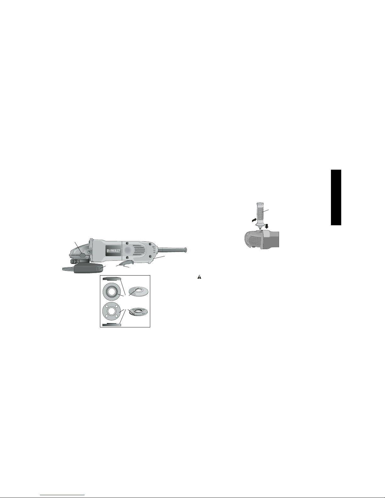
ATTACHING SIDE HANDLE
The side handle can be fitted to either side of the gear case in the
threaded holes, as shown. Before using the tool, check that the
handle is tightened securely. Use a wrench to firmly tighten the
side handle.
Accessories
It is important to choose the correct guards, backing pads and
flanges to use with grinder accessories. See pages 4-5 for information on choosing the correct accessories.
CAUTION: Accessories must be rated for at least the speed
recommended on the tool warning label. Wheels and other accessories running over rated accessory speed may fly apart and
cause injury. Threaded accessories must have a 5/8"-11 hub.
Every unthreaded accessory must have a 7/8" arbor hole. If it
does not, it may have been designed for a circular saw. Use only
the accessories shown on pages 4-5 of this manual. Accessory
ratings must be above listed minimum wheel speed as shown on
tool nameplate.
E
• Avoid prolonged contact with dust from power sanding,
sawing, grinding, drilling, and other construction
activities. Wear protective clothing and wash exposed areas
with soap and water. Allowing dust to get into your mouth, eyes,
or lay on the skin may promote absorption of harmful chemicals.
COMPONENTS
A. Paddle Switch F. Lock-On Button
B. Lock-Off Lever G. Unthreaded Backing Flange
C. Spindle Lock Button H. Threaded Clamp Nut
D. Spindle (not shown) I. Guard
E. Side Handle
(shown on the right)
H
A
B
C
F
G
I
Page 6
English
4
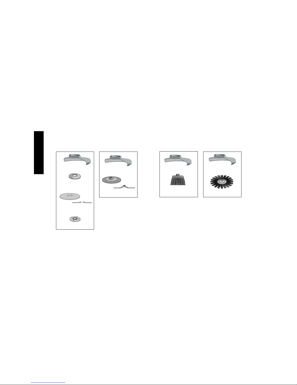
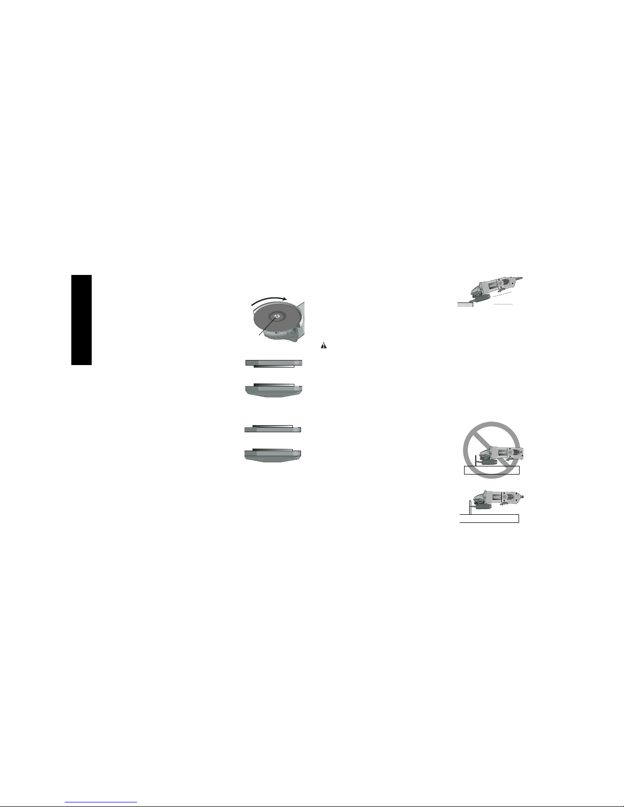
Type 27 guard
4 1/2" Grinding Wheels
unthreaded
backing flange
threaded clamp nut
Type 27 hubbed wheel
Type 27 guard
Type 27 depressed
center wheel
Wire Wheels
3" wire cup
brush
4" wire wheel
Type 27 guard
Type 27 guard
Page 7
English
5
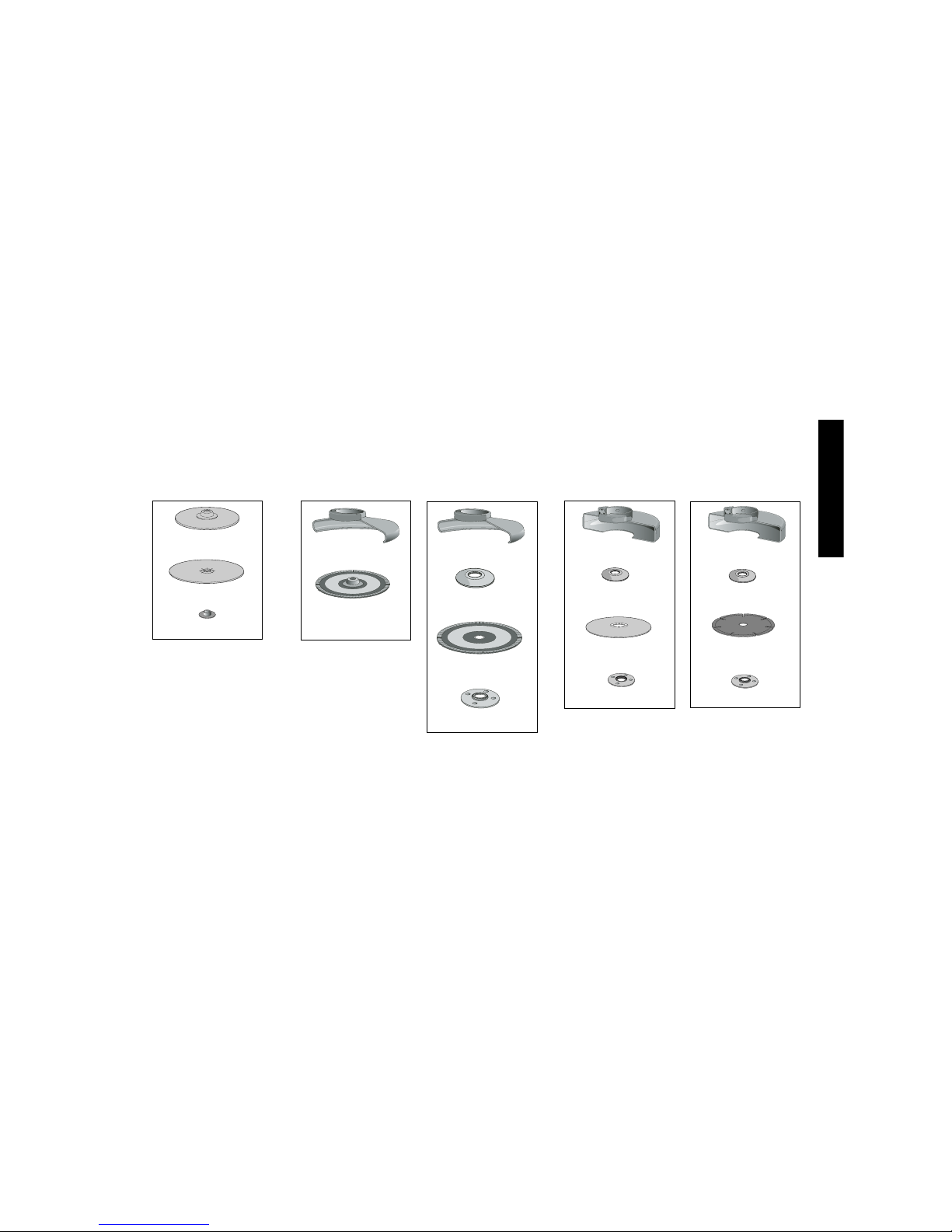
4 1/2" Sanding Flap Discs
hubbed sanding
flap disc
unthreaded backing
flange
non-hubbed sanding
flap disc
threaded clamp nut
rubber backing pad
sanding disc
threaded clamp nut
Sanding Discs
4 1/2" Cutting Wheels
Type 1 guard
backing flange
abrasive cutting wheel
clamp nut
Type 1 guard
backing flange
diamond cutting wheel
clamp nut
Type 27 guard
Type 27 guard
Page 8

English
6
Mounting Guard
MOUNTING AND REMOVING GUARD
CAUTION: Turn off and unplug the tool before making any
adjustments or removing or installing attachments or accessories. Before reconnecting the tool, depress and release the
paddle switch to ensure that the tool is off.
CAUTION: Guards must be used with all grinding wheels,
sanding flap discs, wire brushes, and wire wheels. The tool
may be used without a guard only when sanding with conventional
sanding discs. D
E
WALT model DW802 is provided with a guard
intended for use with depressed center wheels (Type 27) and
hubbed grinding wheels (Type 27). The same guard is designed for
use with sanding flap discs (Type 27 and 29) and wire cup brushes. Grinding and cutting with wheels other than Type 27 and 29
require different accessory guards not included with tool. Mounting
instructions for these accessory guards are included in the accessory package.
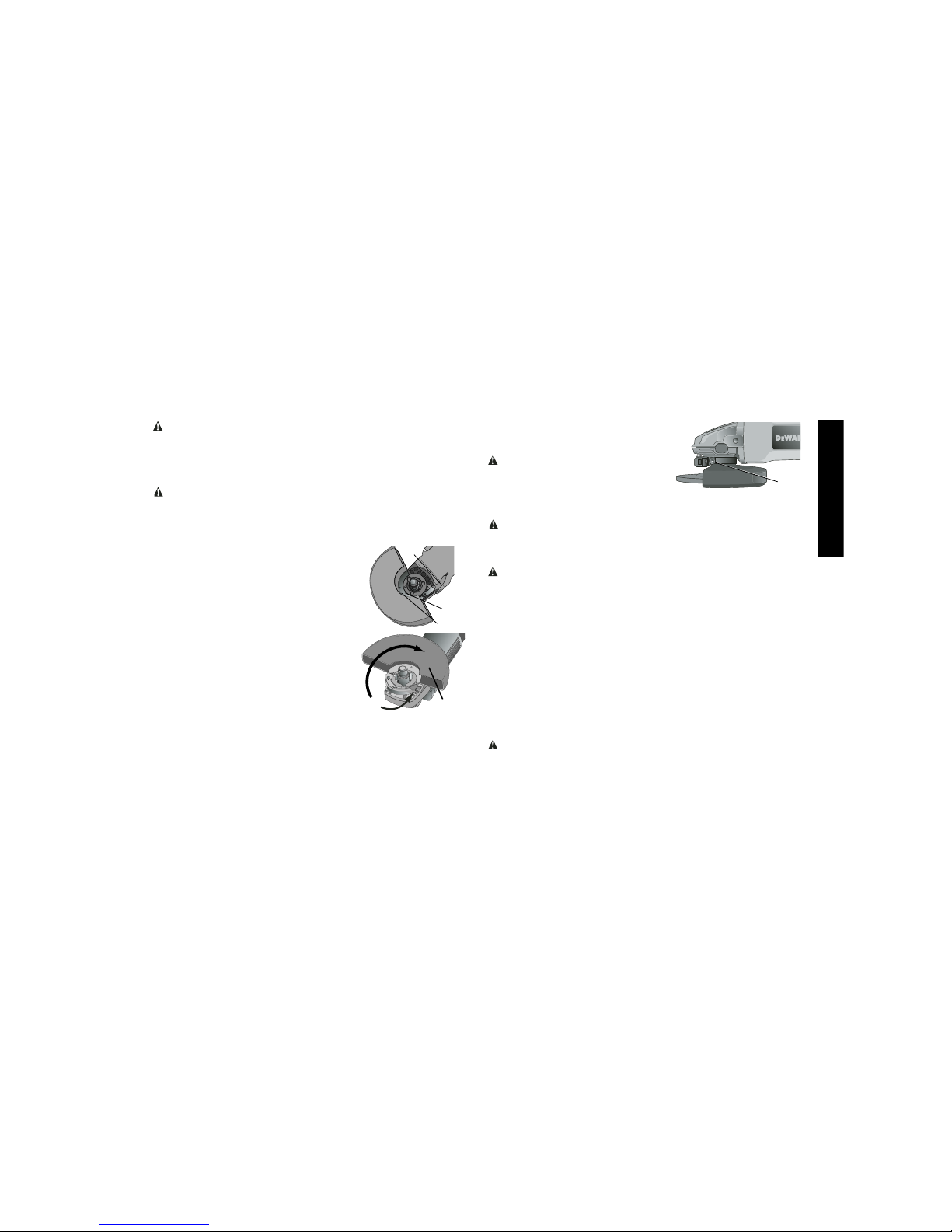
1. Open the guard latch (J), and align the
arrow on the guard (K) with the arrow
on the hub (L). This will align the lugs
on the guard with the slots on the gear
case cover.
2. Push the guard down until the guard
lugs engage and rotate freely in the
groove on the gear case hub.
3. With the guard latch open, rotate the
guard (I) into the desired working position. The guard body should be positioned between the spindle and the
operator to provide maximum operator protection.
4. Close the guard latch to secure the guard on the gear case. You
should not be able to rotate the guard by hand when the latch is
closed. Do not operate the grinder with a loose guard or the
clamp lever in open position.
5. To remove the guard, open the guard latch, rotate the guard so
that the arrows are aligned and pull up on the guard.
NOTE: The guard is pre-adjusted to the
diameter of the gear case hub at the factory.
If, after a period of time, the guard becomes
loose, tighten the adjusting screw (M) with
clamp lever in the closed position.
CAUTION: Do not tighten the adjusting screw with the clamp
lever in open position. Undetectable damage to the guard or the
mounting hub may result.
CAUTION: If guard cannot be tightened by adjusting clamp, do
not use tool and take the tool and guard to a service center to repair
or replace the guard.
NOTE: Edge grinding and cutting can be performed with type 27
wheels designed and specified for this purpose; 1/4" thick wheels
are designed for surface grinding while 1/8" wheels are designed
for edge grinding.
OPERATION
Switch
CAUTION: Before connecting the tool to a power source
depress and release the paddle switch (A) once without depressing
the lock-on button (F) to ensure that the switch is off. Depress and
release the paddle switch as described above after any interruption
in power supply to the tool, such as the activation of a ground fault
interrupter, throwing of a circuit breaker, accidental unplugging, or
power failure. If the paddle switch is locked on, the tool will start
unexpectedly when it is reconnected.
M
I
J
L
K
Page 9
English
7
while the tool is operating because damage to the tool will result. To
engage the lock, depress the spindle lock button and rotate the
spindle until you are unable to rotate the spindle further.
Mounting and Using Depressed
Center Grinding Wheels and
Sanding Flap Discs
MOUNTING AND REMOVING HUBBED WHEELS
CAUTION: Turn off and unplug the tool before making any
adjustments or removing or installing attachments or accessories. Before reconnecting the tool, depress and release the
paddle switch to ensure that the tool is off.
Hubbed wheels install directly on the 5/8"-11 threaded spindle.
1. Thread the wheel on the spindle by hand.
2. Depress the spindle lock button and use a wrench to tighten the
hub of the wheel.
3. Reverse the above procedure to remove the wheel.
CAUTION: Failure to properly seat the wheel before turning the
tool on may result in damage to the tool or the wheel.
MOUNTING NON-HUBBED WHEELS
CAUTION: Turn off and unplug the tool before making any
adjustments or removing or installing attachments or accessories. Before reconnecting the tool, depress and release the
paddle switch to ensure that the tool is off.
Depressed center Type 27 grinding wheels
must be used with included flanges. See
page 5 of this manual for more information.
1. Install the unthreaded backing flange (G)
on spindle (D) with the raised section (pilot)
against the wheel.
CAUTION: Hold the side handle and body of the tool firmly to
maintain control of the tool at start up and during use and until the
wheel or accessory stops rotating. Make sure the wheel has come
to a complete stop before laying the tool down.
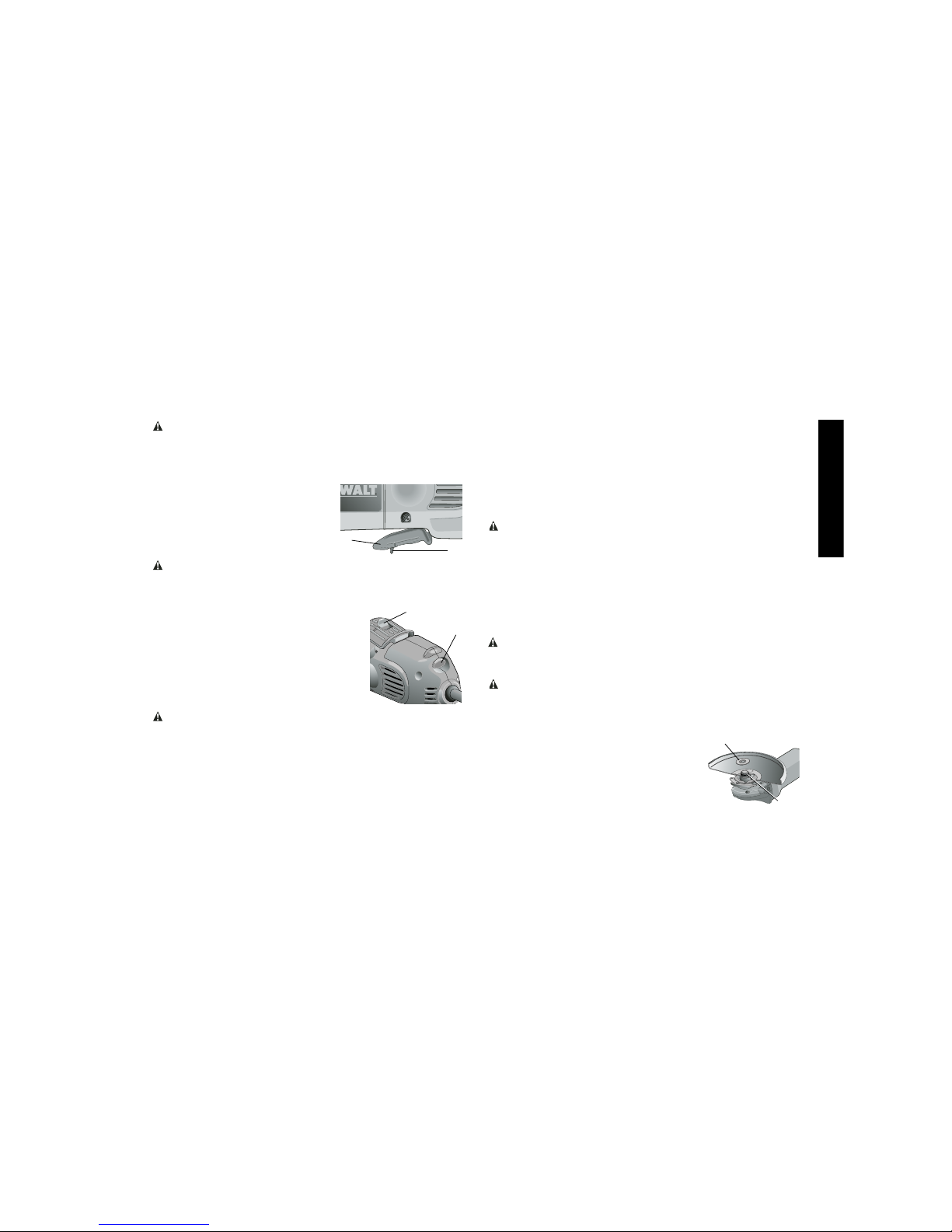
PADDLE SWITCH
To turn the tool on, push the lock-off
lever (B) toward the back of the tool,
then depress the paddle switch (A).
The tool will run while the switch is
depressed. Turn the tool off by
releasing the paddle switch.
WARNING: Do not disable the lock-off lever. If the lock-off lever
is disabled, the tool may start unexpectedly when it is laid down.
LOCK-ON BUTTON
The lock-on button offers increased comfort
in extended use applications. To lock the tool
on, push the lock-off lever (B) toward the
back of the tool then depress the paddle
switch (A). With the tool running, depress the
lock-on button (F). The tool will continue to
run after the paddle switch is released. To
unlock the tool, depress and release the paddle switch. This will cause the tool to stop.
CAUTION: Allow the tool to reach full speed before touching
tool to the work surface. Lift the tool from the work surface before
turning the tool off.
SPINDLE LOCK
The spindle lock pin is provided to prevent the spindle from rotating
when installing or removing wheels. Operate the spindle lock pin
only when the tool is turned off, unplugged from the power supply,
and has come to a complete stop. Do not engage the spindle lock
7
A
B
B
F
G
D
Page 10
English
8
2. Place wheel against the backing flange, centering the wheel on
the raised section (pilot) of the backing flange.
3. While depressing the spindle lock button, thread the clamp nut (H) on spindle. If the wheel you are installing is
more than 1/8" thick, place the threaded
clamp nut on the spindle so that the
raised section (pilot) fits into the center
of the wheel. If the wheel you are
installing is 1/8" thick or less, place the
threaded clamp nut on the spindle so
that the raised section (pilot) is not
against the wheel.
4. While depressing the spindle lock button, tighten the clamp nut with a wrench.
5. To remove the wheel, depress the spindle lock button and loosen the threaded
clamp nut with a wrench.
NOTE: If the wheel spins after the clamp nut
is tightened, check the orientation of the
threaded clamp nut. If a thin wheel is
installed with the pilot on the clamp nut
against the wheel, it will spin because the
height of the pilot prevents the clamp nut
from holding the wheel.
SURFACE GRINDING WITH GRINDING WHEELS
1. Allow the tool to reach full speed before touching the tool to the
work surface.
2. Apply minimum pressure to the work surface, allowing the tool
to operate at high speed. Grinding rate is greatest when the tool
operates at high speed.
3. Maintain a 20˚ to 30˚ angle between the
tool and work surface.
4. Continuously move the tool in a forward
and back motion to avoid creating gouges
in the work surface.
5. Remove the tool from work surface before turning tool off. Allow
the tool to stop rotating before laying it down.
EDGE GRINDING WITH GRINDING WHEELS
CAUTION: Wheels used for cutting and edge grinding may break
if they bend or twist while the tool is being used to do cut-off work or
deep grinding. To reduce the risk of serious injury, limit the use of
these wheels with a standard Type 27 guard to shallow cutting and
notching (less than 1/2" in depth). The open side of the guard must
be positioned away from the operator. For deeper cutting with a
Type 1 cut-off wheel, use a closed, Type 1 guard. See the chart on
pages 4-5 for more information. Type 1 guards are available at extra
cost from your local dealer or authorized service center.
1. Allow the tool to reach full speed before
touching the tool to the work surface.
2. Apply minimum pressure to the work
surface, allowing the tool to operate at
high speed. Grinding rate is greatest
when the tool operates at high speed.
3. Position yourself so that the openunderside of the wheel is facing away
from you.
4. Once a cut is begun and a notch is
established in the workpiece, do not
change the angle of the cut. Changing
the angle will cause the wheel to bend
and may cause wheel breakage. Edge
1/4" WHEELS
1/8" WHEELS
H
20˚-30˚
Backing Flange
Clamp Nut
Backing Flange
Clamp Nut
Page 11

English
9
1. Place or appropriately thread backing
pad (N) on the spindle.
2. Place the sanding disc (O) on the backing pad (N).
3. While depressing spindle lock, thread
clamp nut (P) on spindle, piloting the
raised hub on the clamp nut into the
center of sanding disc and backing pad.
4. Tighten the clamp nut by hand. Then
depress the spindle lock button while
turning the sanding disc until the sanding disc and clamp nut are snug.
5. To remove the wheel, grasp and turn the backing pad and
sanding pad while depressing the spindle lock button.
USING SANDING BACKING PADS
Choose the proper grit sandpaper for your application. Sandpaper
is available in various grits. Coarse grits yield faster material
removal rates and a rougher finish. Finer grits yield slower material removal and a smoother finish.
Begin with coarse grit discs for fast, rough material removal.
Move to a medium grit paper and finish with a fine grit disc for
optimal finish.
Coarse 16 - 30 grit
Medium 36 - 80 grit
Fine Finishing 100 - 120 grit
Very Fine Finishing 150 - 180 grit
1. Allow the tool to reach full speed before touching tool to the work
surface.
2. Apply minimum pressure to work surface, allowing the tool to
operate at high speed. Sanding rate is greatest when the tool
operates at high speed.
grinding wheels are not designed to withstand side pressures
caused by bending.
5. Remove the tool from the work surface before turning the tool
off. Allow the tool to stop rotating before laying it down.
WARNING: Do not use edge grinding/cutting wheels for surface
grinding applications because these wheels are not designed for
side pressures encountered with surface grinding. Wheel breakage
and injury may result
.
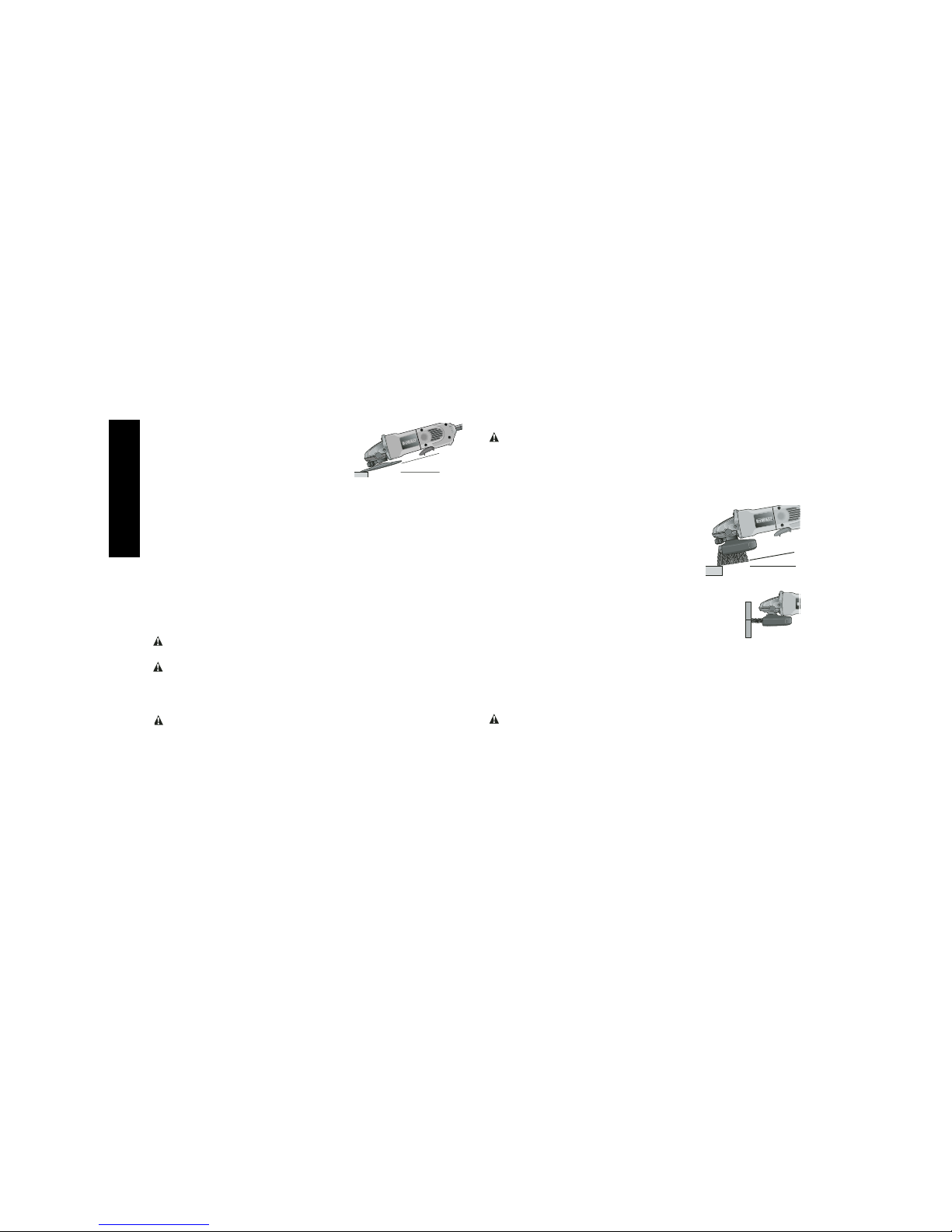
SURFACE FINISHING WITH SANDING FLAP DISCS
1. Allow the tool to reach full speed before touching the tool to the
work surface.
2. Apply minimum pressure to work surface, allowing the tool to
operate at high speed. Sanding rate is greatest when the tool
operates at high speed.
3. Maintain a 5˚ to 10˚ angle between
the tool and work surface.
4. Continuously move the tool in a
forward and back motion to avoid
creating gouges in the work surface.
5. Remove the tool from work surface before turning tool off. Allow
the tool to stop rotating before laying it down.
MOUNTING SANDING BACKING PADS
CAUTION: Turn off and unplug the tool before making any
adjustments or removing or installing attachments or accessories. Before reconnecting the tool, depress and release the
paddle switch to ensure that the tool is off.
CAUTION: Proper guard must be reinstalled for grinding
wheel, sanding flap disc, wire brush or wire wheel applications
after sanding applications are complete.
P
N
O
5˚-10˚
Page 12
English
10
3. Maintain a 5˚ to 15˚ angle between the
tool and work surface. The sanding
disc should contact approximately
one inch of work surface.
4. Move the tool constantly in a straight
line to prevent burning and swirling of work surface. Allowing the
tool to rest on the work surface without moving, or moving the
tool in a circular motion causes burning and swirling marks on
the work surface.
5. Remove the tool from work surface before turning tool off. Allow
the tool to stop rotating before laying it down.
Mounting and Using Wire Brushes
and Wire Wheels
Wire cup brushes or wire wheels screw directly on the grinder spindle without the use of flanges. Use only wire brushes or wheels provided with a 5/8"-11 threaded hub. A Type 27 guard is required
when using wire brushes and wheels.
CAUTION: Wear work gloves when handling wire brushes
and wheels. They can become sharp.
CAUTION: Wheel or brush must not touch guard when mounted
or while in use. Undetectable damage could occur to the accessory,
causing wires to fragment from accessory wheel or cup.
MOUNTING WIRE CUP BRUSHES AND WIRE WHEELS
CAUTION: Turn off and unplug the tool before making any
adjustments or removing or installing attachments or accessories. Before reconnecting the tool, depress and release the
paddle switch to ensure that the tool is off.
1. Thread the wheel on the spindle by hand.
2. Depress spindle lock button and use a wrench on the hub of the
wire wheel or brush to tighten the wheel.
3. To remove the wheel, reverse the above procedure.
CAUTION: Failure to properly seat the wheel hub before turning
the tool on may result in damage to tool or wheel.
USING WIRE CUP BRUSHES AND WIRE WHEELS
Wire wheels and brushes can be used for removing rust, scale and
paint, and for smoothing irregular surfaces.
1. Allow the tool to reach full speed before
touching the tool to the work surface.
2. Apply minimum pressure to work surface,
allowing the tool to operate at high speed.
Material removal rate is greatest when the
tool operates at high speed.
3. Maintain a 5˚ to 10˚ angle between the tool
and work surface for wire cup brushes.
4. Maintain contact between the edge of the wheel
and the work surface with wire wheels.
5. Continuously move the tool in a forward and
back motion to avoid creating gouges in the work
surface. Allowing the tool to rest on the work surface without
moving, or moving the tool in a circular motion causes burning
and swirling marks on the work surface.
6. Remove the tool from the work surface before turning the tool
off. Allow the tool to stop rotating before setting it down.
CAUTION: Use extra care when working over an edge, as a
sudden sharp movement of grinder may be experienced.
Mounting and Using Cutting
(Type 1) Wheels
Cutting wheels include diamond wheels and abrasive discs.
Abrasive cutting wheels for metal and concrete use are available.
Diamond blades for concrete cutting can also be used.
5˚-15˚
5˚-10˚
Page 13
English
11
loose, tighten the adjusting screw (M)
with the clamp lever in the closed
position.
CAUTION: Do not tighten adjust-
ing screw with clamp lever in open
position. Undetectable damage to
guard or mounting hub may result.
MOUNTING CUTTING WHEELS
CAUTION: Turn off and unplug the tool before making any
adjustments or removing or installing attachments or accessories. Before reconnecting the tool, depress and release the
paddle switch to ensure that the tool is off.
CAUTION: Matching diameter threaded backing flange and
clamp nut (included with tool) must be used for cutting wheels.
1. Place the unthreaded backing flange on spindle with the raised
section (pilot) facing up. The raised section (pilot) on the backing
flange will be against the wheel when the wheel is installed.
2. Place the wheel on the backing flange, centering the wheel on
the raised section (pilot).
3. Install the threaded clamp nut with the raised section (pilot)
facing away from the wheel.
4. Depress the spindle lock button and tighten clamp nut with
a wrench.
5. To remove the wheel, grasp and turn while depressing the
spindle lock button.
USING CUTTING WHEELS
WARNING: Do not use edge grinding/cutting wheels for surface
grinding applications because these wheels are not designed for
side pressures encountered with surface grinding. Wheel breakage
and injury may result.
1. Allow tool to reach full speed before touching tool to work
surface.
WARNING: A closed, 2-sided cutting wheel guard is not included
with this tool but is required when using cutting wheels. Failure to
use proper flange and guard can result in injury resulting from wheel
breakage and wheel contact. See page 7 for more information.
MOUNTING CLOSED (TYPE 1) GUARD
CAUTION: Turn off and unplug the tool before making any
adjustments or removing or installing attachments or accessories. Before reconnecting the tool, depress and release the
paddle switch to ensure that the tool is off.
1. Open the guard latch (J), and align the
arrow on the guard (K) with the arrow
on the hub (L). This will align the lugs
with slots on the gear case cover.
Position the guard facing backward.
2. Push the guard down until the guard lug
engages and rotates freely in the
groove on the gear case hub.
3. Rotate guard (I) into desired working
position. The guard body should be
positioned between the spindle and the
operator to provide maximum operator
protection.
4. Close the guard latch to secure the
guard on the gear case cover. You
should be unable to rotate the guard by hand when the latch is
in closed position. Do not operate grinder with a loose guard or
clamp lever in open position.
5. To remove the guard, open the guard latch, rotate the guard so
that the arrows are aligned and pull up on the guard.
NOTE: The guard is pre-adjusted to the diameter of the gear case
hub at the factory. If, after a period of time, the guard becomes
M
J
L
K
I
Page 14

English
12
2. Apply minimum pressure to work surface, allowing tool to
operate at high speed. Cutting rate is
greatest when the tool operates at high
speed.
3. Once a cut is begun and a notch is estab-
lished in the workpiece, do not change the
angle of the cut. Changing the angle will
cause the wheel to bend and may cause
wheel breakage.
4. Remove the tool from work surface before
turning tool off. Allow the tool to stop rotating
before setting it down.
MAINTENANCE
Cleaning
WARNING: Blow dust and grit out of the motor housing regularly
using clean, dry compressed air. Dust and grit containing metal
particles often accumulate on interior surfaces and could create an
electrical shock hazard if not frequently cleaned out. ALWAYS
WEAR SAFETY GLASSES.
CAUTION: Never use solvents or other harsh chemicals
for cleaning the non-metallic parts of the tool. Use a clean, dry
cloth only.
Lubrication
DEWALT tools are properly lubricated at the factory and are ready
for use.
Repairs
To assure product SAFETY and RELIABILITY, repairs, maintenance
and adjustment (including brush inspection and replacement)
should be performed by a D
EWALT factory service center, a
D
EWALT authorized service center or other qualified service per-
sonnel. Always use identical replacement parts.
Purchasing Accessories
Recommended accessories for use with your tool are available at
extra cost from your local dealer or authorized service center. If you
need assistance in locating any accessory for your tool, please
contact D
EWALT Industrial Tool Co., 701 East Joppa Road,
Baltimore, MD 21286, call 1-800-4-D
EWALT (1-800-433-9258) or
visit our website www.dewalt.com.
CAUTION: The use of any other accessory not recommended
for use with this tool could be hazardous.
Three Year Limited Warranty
DEWALT will repair, without charge, any defects due to faulty materials or workmanship for three years from the date of purchase.
This warranty does not cover part failure due to normal wear or tool
abuse. For further detail of warranty coverage and warranty repair
information, visit www.dewalt.com or call 1-800-4-D
EWALT (1-800-
433-9258). This warranty does not apply to accessories or damage
caused where repairs have been made or attempted by others.
This warranty gives you specific legal rights and you may have
other rights which vary in certain states or provinces.
In addition to the warranty, D
EWALT tools are covered by our:
1 YEAR FREE SERVICE
D
EWALT will maintain the tool and replace worn parts caused by
normal use, for free, any time during the first year after purchase.
90 DAY MONEY BACK GUARANTEE
If you are not completely satisfied with the performance of your
D
EWALT Power Tool, Laser, or Nailer for any reason, you can
return it within 90 days from the date of purchase with a receipt for
a full refund – no questions asked.
Page 15

English
13
LATIN AMERICA: This warranty does not apply to products sold in
Latin America. For products sold in Latin America, see country specific warranty information contained either in the packaging, call the
local company or see website for warranty information.
FREE WARNING LABEL REPLACEMENT: If your warning labels
become illegible or are missing, call 1-800-4-D
EWALT for a free
replacement.
Page 16

Français
14
CONSERVER CES DIRECTIVES
AVERTISSEMENT! S’assurer de lire et de bien comprendre
toutes les directives, y compris celles fournies avec les
pièces et accessoires. Le non-respect des directives présentées
ci-dessous pourrait causer un choc électrique, un incendie et/ou
des blessures graves.
POUR TOUTE QUESTION OU REMARQUE AU SUJET DE CET
OUTIL OU DE TOUT AUTRE OUTIL D
EWALT, COMPOSER LE
NUMÉRO SANS FRAIS :
1 800 4-DEWALT (1 800 433-9258)
Directives de sécurité d’ordre général
AIRE DE TRAVAIL
• L’aire de travail doit être propre et bien éclairée. Les établis
encombrés et le manque de lumière peuvent entraîner des
accidents.
• Ne pas faire fonctionner des outils électriques dans des
atmosphères explosives, comme en présence de liquides,
de gaz et de poussières inflammables. Les outils électriques
produisent des étincelles qui peuvent enflammer la poussière
ou les vapeurs.
• Tenir les spectateurs, les enfants et les visiteurs à l’écart
lorsqu’on utilise l’outil. Les distractions peuvent entraîner
une perte de maîtrise.
RÈGLES DE SÉCURITÉ RELATIVES À L’ÉLECTRICITÉ
• Les outils mis à la terre doivent être branchés dans une
prise correctement installée et mise à la terre tel que
l’indiquent les codes et règlements en vigueur. Ne jamais
retirer la broche de mise à la terre ou modifier la prise en
aucune façon. Ne pas utiliser de fiche d’adaptation.
Consulter un électricien qualifié s’il y a un doute en ce qui
concerne la mise à la terre de la prise. En cas de mauvais
fonctionnement ou de bris des outils, la mise à la terre offre un
chemin de faible résistance afin d’empêcher l’électrocution de
l’utilisateur. S’applique uniquement aux outils de classe I
(mis à la terre).
• Les outils à double isolation sont pourvus d’une fiche
polarisée (une lame est plus large que l’autre). Cette fiche
ne peut être branchée dans une prise polarisée que dans
un seul sens. Si la fiche ne peut être branchée dans la
prise, inverser la fiche. Si on n’arrive toujours pas à la
brancher, communiquer avec un électricien qualifié afin
qu’il installe une prise polarisée. Ne pas modifier la fiche.
La double isolation évite de recourir à une rallonge d’alimentation trifilaire et à un bloc d’alimentation mis à la terre.
S’applique uniquement aux outils de classe II (à double
isolation).
• Éviter tout contact corporel avec des surfaces mises à la
terre, comme des tuyaux, des radiateurs, des cuisinières
et des réfrigérateurs. Le risque de choc électrique augmente
si le corps est mis à la terre.
• Ne pas exposer les outils électriques à la pluie ni à l’eau.
Si de l’eau pénètre dans un outil électrique, le risque d’électrocution augmente.
• Manipuler le cordon avec soin. Ne jamais s’en servir pour
transporter l’outil ou pour tirer la fiche hors de la prise. Tenir
le cordon à l’écart de la chaleur, de l’huile, des arêtes vives
ou des pièces mobiles. Remplacer immédiatement les cordons endommagés car ils augmentent le risque d’électrocution.
• Lorsqu’on utilise un outil électrique à l’extérieur, il faut
employer une rallongeportant l’inscription “W-A” ou “W.”
Ces rallonges sont conçues pour l’utilisation à l’extérieur et
réduisent le risque d’électrocution.
Page 17

Français
15
Calibre minimal des cordons de rallonge
Tension Longueur totale du cordon en mètres
120 V De 0 à 7 De 7 à 15 De 15 à 30 De 30 à 45
240 V De 0 à 7 De 7 à 15 De 15 à 39 De 30 à 45
Intensité (A)
Au Au Calibre moyen de fil
moins plus
6 - 10 18 16 14 12
SÉCURITÉ PERSONNELLE
• Demeurer alerte, prêter attention à ce que l’on fait et faire
preuve de bons sens lorsqu’on utilise un outil électrique.
Ne pas utiliser un outil lorsqu’on ressent de lafatigue ou
après avoir consommé des drogues, de l’alcool ou
desmédicaments. Un moment d’inattention durant l’utilisation
d’outils électriques peut entraîner de graves blessures.
• Porter des vêtements appropriés. Ne pas porter de
vêtements amples ni de bijoux. Attacher les cheveux longs.
Tenir les cheveux, les vêtements et les gants à l’écart des
pièces mobiles. Les vêtements amples, les bijoux et les
cheveux longs peuvent être happés par des pièces mobiles. Il
faut également se tenir à l’écart des évents qui recouvrent
souvent les pièces mobiles.
• Éviter le démarrage accidentel. S’assurer que l’interrupteur
est en position d’arrêt avant de brancher l’outil.Le fait de
transporter un outil en appuyant sur la gâchette ou de le
brancher lorsque l’interrupteur se trouve en position de marche
peut causer des accidents.
• Déposer les clés de réglage ou de serrage avant de mettre
l’outil sous tension. Si une clé demeure fixée à une pièce
rotative de l’outil, des blessures peuvent survenir.
• Ne pas tendre le bras trop loin. Il faut demeurer en équilibre
en tout temps. Un bon équilibre permet une meilleure maîtrise
de l’outil dans les situations inattendues.
• Utiliser du matériel de sécurité. Toujours porter des
lunettes de protection. Il faut utiliser, au besoin, un masque
anti-poussières, des chaussures de sécurité antidérapantes, un
casque de sécurité ou des protecteurs d’oreilles.
UTILISATION DES OUTILS ET PRÉCAUTIONS
• Utiliser des pinces ou un autre moyen pratique de fixer et de
soutenir la pièce à travailler sur une plateforme stable. Le fait
de tenir la pièce avec la main ou de l’appuyer contre le corps ne
permet pas de la stabiliser et cela risque de causer une perte de
maîtrise.
• Ne pas forcer l’outil. Utiliser celui qui convient au travail à
effectuer. L’outil adéquat permet de faire le travail de façon plus
convenable et sûre lorsqu’il est employé suivant l’utilisation pour
laquelle il a été conçu.
• Ne pas utiliser l’outil si l’interrupteur ne permet pas de le
mettre sous ou hors tension. Tout outil impossible à
commander au moyen de l’interrupteur est dangereux et doit
être réparé.
• Débrancher la fiche de la source d’alimentation avant
d’effectuer des réglages, de changer d’accessoire ou de
ranger l’outil. De telles mesures préventives réduisent le risque
de le mettre en marche accidentellement.
• Ranger les outils hors de la portée des enfants et des autres
personnes non qualifiées. Les outils sont dangereux entre les
mains d’utilisateurs non qualifiés.
• Veiller à entretenir correctement les outils. Affûter et
nettoyer les accessoires de coupe. Des outils bien
entretenus, et dont les arêtes sont coupantes, sont moins
susceptibles de se coincer et sont plus faciles à manier.
• Vérifier la présence de pièces mobiles mal alignées ou
coincées, de pièces brisées ou de toute autre condition
pouvant nuire au fonctionnement de l’outil. Si l’outil est
Page 18

Français
16
endommagé, il faut le faire réparer avant de l’utiliser. De
nombreux accidents sont causés par des outils mal entretenus.
• Utiliser seulement des accessoires recommandés par le
fabricant du modèle. Des accessoires convenant à un outil
peuvent être dangereux lorsqu’on les installe sur un autre outil.
RÉPARATION
• Seules des personnes qualifiées peuvent réparer les outils. Une réparation ou un entretien effectué par une personne
non qualifiée risque d’entraîner des blessures.
• Il faut utiliser uniquement des pièces de rechange identiques pour réparer un outil. Suivre les directives figurant
dans la section Entretien du présent manuel. L’emploi de
pièces inadéquates ou le non-respect des directives d’entretien
peut provoquer un choc électrique ou des blessures.
Consignes de sécurité particulières
relatives aux meuleuses
• Utiliser toujours le protecteur convenant à la meule. Il pro-
tège l’utilisateur contre les projections de fragments en cas de
bris et empêche tout contact avec la meule.
• Les accessoires doivent être conçus au moins pour le
régime recommandé sur l’étiquette d’avertissement de
l’outil. Les meules et autres accessoires tournant à un régime
supérieur à la vitesse nominale peuvent se désintégrer et
causer des blessures. Le régime nominal des accessoires doit
être supérieur à la vitesse minimale de la meule, telle
qu’indiquée sur la plaque signalétique de l’outil.
• Tenir l’outil par les surfaces de saisie isolées pour les
travaux où l’outil de coupe risque de toucher à des fils
dissimulés ou au cordon d’alimentation. Tout contact avec un
fil “sous tension” provoquera “l’électrisation“ des parties
métalliques exposées et l’électrocution de l’utilisateur.
• Ne pas utiliser des meules de type 11 (meules boisseaux
coniques) sur cet outil. L’utilisation d’accessoires non
appropriés pourrait causer des blessures.
• Avant d’utiliser les accessoires recommandés, s’assurer
qu’ils ne présentent aucune fissure ou défectuosité. Si une
fissure ou défectuosité est évidente, mettre l’accessoire au
rebut. Il faut également vérifier l’accessoire si l’on
soupçonne que l’outil a subi une chute. Un accessoire
défectueux pourrait entraîner le bris de la meule.
• Lorsqu’on démarre l’outil après y avoir installé une meule
ou une brosse métallique, neuve ou de rechange, tenir
l’outil dans un endroit bien protégé et le faire fonctionner
pendant une minute. Si la meule comporte une fissure ou une
défectuosité non détectée, elle devrait se désintégrer en moins
d’une minute. S’il y a des fils lâches dans la brosse métallique,
ils seront détectés. Ne jamais mettre l’outil en marche lorsqu’une
personne est placée dans l’axe de la meule. Cette mesure
s’applique également à l’utilisateur.
• Éviter de faire rebondir la meule ou de l’utiliser de façon
abusive. Si cela se produit, arrêter l’outil et vérifier s’il y a
présence de fissure ou de défectuosité.
• Orienter les étincelles dans la direction opposée à
l’utilisateur et aux autres personnes présentes ou de tout
matériau inflammable. L’utilisation d’une meuleuse ou d’une
ponceuse peut produire des étincelles qui risquent de causer des
brûlures ou des incendies.
• Utiliser toujours la poignée latérale et la serrer solidement.
Il faut toujours se servir de la poignée latérale pour maîtriser
l’outil en tout temps.
• Ne pas utiliser cet outil pendant des périodes prolongées.
Les vibrations causées par l’action de fonctionnement de l’outil
peuvent blesser en permanence les doigts, les mains et les
Page 19

Français
17
bras. Porter des gants pour amortir les vibrations, faire des
pauses fréquentes et limiter le temps d’utilisation quotidien de
l’outil.
• Nettoyer l’outil fréquemment, plus particulièrement s’il est
soumis à une utilisation intensive. De la poussière contenant
des particules métalliques s’accumule souvent sur les surfaces
intérieures et pourrait provoquer un choc électrique.
• L’étiquette apposée sur l’outil peut comprendre les symboles
suivants :
V ..............volts
A ..............ampères
Hz ............hertz
W ............watts
min ..........minutes
............courant alternatif
........courant direct
n
o ............régime sans charge
............
fabrication de classe II
............symbole d’alerte relative à la sécurité
............
borne de mise à la terre
…/min ......mouvement alternatif ou tours par minute
MISE EN GARDE : Le meulage à l’intérieur d’un angle peut
créer un soudain mouvement brusque de l’outil si la meule ou un
autre accessoire touche à une surface secondaire ou à toute autre
surface. Il faut donc être très vigilant.
MISE EN GARDE : Porter des protecteurs d’oreilles
appropriés durant l’utilisation. Selon les conditions et la durée
d’utilisation, le bruit émis par cet outil peut causer une perte auditive.
AVERTISSEMENT : Certaines poussières créées par le
ponçage, le sciage, le meulage et le forage mécanique ainsi que
d’autres activités de construction contiennent des produits
chimiques susceptibles de causer le cancer, des anomalies
congénitales ou d’autres anomalies liées à la reproduction. Parmi
ces produits chimiques, citons notamment :
• le plomb des peintures au plomb;
• la silice cristalline provenant des briques, du béton et autres
matériaux de maçonnerie;
• l’arsenic et le chrome provenant du bois traité (arséniate de
cuivre et de chrome).
Le risque associé à ces expositions varie selon la fréquence de ces
types de travaux. Pour réduire l’exposition aux produits chimiques :
travailler dans un local bien ventilé et utiliser du matériel de sécurité
approuvé, comme les masques anti-poussières spécialement
conçus pour filtrer les particules microscopiques.
• Éviter le contact prolongé avec la poussière provenant du
ponçage, du sciage, du meulage et du forage mécanique
ainsi que d’autres activités de construction. Porter des
vêtements de protection et laver les parties exposées au
savon et à l’eau. La poussière qui pourrait pénétrer dans la
bouche et les yeux ou se déposer sur la peau peut favoriser
l’absorption de produits chimiques nocifs.
Page 20

Français
18
ASSEMBLAGE ET RÉGLAGES
FIXATION DE LA POIGNÉE LATÉRALE
La poignée latérale peut être fixée dans les orifices filetés situés sur
un côté ou l’autre du carter d’engrenage, comme le montre
l’illustration. Avant d’utiliser l’outil, s’assurer que la poignée est bien
serrée. Utiliser une clé pour la serrer fermement.
Accessoires
Il est important de choisir les écrans protecteurs, plateaux portedisque et brides qui conviennent aux accessoires de meulage. Voir
les pages 19 et 20 pour obtenir plus de renseignements quant aux
accessoires appropriés.
MISE EN GARDE : Les accessoires doivent être conçus au moins
pour le régime recommandé sur l’étiquette d’avertissement de l’outil.
Les meules et autres accessoires tournant à un régime supérieur à la
vitesse nominale des accessoires peuvent se désintégrer et causer
des blessures. Les accessoires filetés doivent être montés sur un
moyeu de 5/8 po-11. Tous les accessoires non-filetés doivent avoir un
orifice d’arbre de 7/8 po. Si ce n’est pas le cas, il est possible qu’ils
aient été conçus pour une scie circulaire. Utiliser uniquement les
accessoires illustrés aux pages 19 et 20 du présent manuel. Le
régime nominal des accessoires doit être supérieur à la vitesse
minimale de la meule, telle qu’indiquée sur la plaque signalétique de
l’outil.
E
COMPOSANTES
A. Interrupteur à palette F. Bouton de verrouillage
B. Levier de déverrouillage G. Bride de support non-filetée
C. Bouton de verrouillage H. Écrou de la bride filetée
de la broche I. Protecteur
D. Broche (non illustrée)
E. Poignée latérale
(illustrée à droite)
H
A
B
C
F
G
I
Page 21

Français
19
Protecteur de
type 27
Meules de 4 1/2 po
Bride de support
non filetée
Écrou de bride filetée
Meule à moyeu
de type 27
Protecteur de
type 27
Meule à moyeu
déporté de type 27
Brosses métalliques circulaires
Brosse forme
coupelle de 3 po
Meule métallique
de 4 po
Protecteur de
type 27
Protecteur de
type 27
Page 22

Français
20
Disques de ponçage
de 4 1/2 po
Disque de
ponçage à moyeu
Bride de support non
filetée
Disque de ponçage
sans moyeu
Écrou de bride filetée
Plateau porte-disque
en caoutchouc
Disque de ponçage
Écrou de bride filetée
Disques de
ponçage
Meules à tronçonner de 4 1/2 po
Protecteur de type 1
Bride de support
Meules abrasives à
tronçonner
Écrou de bride
Protecteur de type 1
Bride de support
Meules à diamant à
tronçonner
Écrou de bride
Protecteur de type 27
Protecteur de type 27
Page 23

Français
21
Installation du protecteur
INSTALLATION ET DÉPOSE DU PROTECTEUR
MISE EN GARDE : Mettre l’outil hors tension et le débrancher
avant d’y apporter des réglages, de retirer ou d’installer des
accessoires. Avant de brancher l’outil à nouveau, appuyer sur
l’interrupteur à palette, puis le relâcher pour s’assurer que
l’outil est bien hors tension.
MISE EN GARDE : Le protecteur doit être utilisé avec les
meules, les disques de ponçage, les brosses métalliques ou les
brosses métalliques circulaires. Il est possible d’utiliser l’outil sans
le protecteur pour le ponçage avec des disques ordinaires. Le
modèle DW802 de D
E
WALT comprend un protecteur que l’on doit
utiliser pour les travaux exigeant une meule à moyeu déporté (de
type 27) ou une meule montée sur moyeu (de type 27). Ce même
protecteur est conçu pour être utilisé avec les disques de ponçage
(de type 27 et 29) et les brosses forme coupelle. Un protecteur de
modèle différent et non compris avec l’outil est requis pour le
meulage ou le tronçonnage à l’aide de meules autres que celles de
type 27 et 29. Les directives d’installation sont comprises dans
l’emballage de ces protecteurs et accessoires.
1. Ouvrir le verrou du protecteur (J) et
aligner la flèche du protecteur (K) avec
celle du moyeu (L). Ceci permettra
d’aligner les pattes du protecteur avec
les fentes sur le couvercle du carter
d’engrenage.
2. Abaisser le protecteur jusqu’à ce que
les pattes s’enclenchent et tournent
librement dans la rainure sur le moyeu
du carter d’engrenage.
3. Alors que le verrou du protecteur est
ouvert, tourner le protecteur (I) jusqu’à
ce qu’il soit à la position désirée. Le
corps du protecteur doit être placé
entre la broche et l’utilisateur de sorte
que ce dernier soit bien protégé.
4. Fermer le verrou du protecteur pour le fixer sur le carter
d’engrenage. Lorsque le verrou est bien fermé, il ne sera pas
possible de faire tourner le protecteur manuellement. Ne pas
utiliser la meuleuse si le protecteur n’est pas bien serré ou si le
levier de la bride est en position ouverte.
5. Pour retirer le protecteur, ouvrir le verrou, tourner le protecteur de
sorte que les flèches soient alignées et tirer le protecteur vers le
haut.
NOTA : Le protecteur est réglé en usine
selon le diamètre du moyeu du carter
d’engrenage. Si le protecteur se desserre
après un certain temps, serrer la vis de
réglage (M) alors que le levier de la bride est
en position fermée.
MISE EN GARDE : Ne pas serrer la vis de réglage si le levier de
la bride est en position ouverte. Ceci risquerait de causer des
dommages invisibles au protecteur ou au moyeu.
MISE EN GARDE : S'il est impossible de serrer le protecteur en
réglant la bride, ne pas utiliser d'outil; apporter l'outil et le protecteur à
un centre de service afin d'y faire réparer ou remplacer le protecteur.
NOTA : Le tronçonnage et le découpage peuvent être effectués
avec des meules de type 27 conçues spécifiquement pour ce genre
de travail; le meulage de surface s’effectue à l’aide de meules de 1/4
po alors que le tronçonnage s’effectue à l’aide de meules de 1/8 po.
M
I
J
L
K
Page 24

Français
22
BOUTON DE VERROUILLAGE
Le bouton de verrouillage offre un plus
grand confort quand le travail demande plus
de temps. Pour verrouiller l’outil, ramener le
levier de déverrouillage (B) vers l’arrière,
puis enfoncer l’interrupteur à palette (A).
Lorsque l’outil est en marche, enfoncer le
bouton de verrouillage (F). L’outil continuera
de fonctionner une fois que l’interrupteur
sera relâché. Pour déverrouiller l’outil, appuyer sur l’interrupteur et
le relâcher. L’outil s’arrêtera.
MISE EN GARDE : Laisser l’outil atteindre le régime maximal
avant qu’il ne touche à la surface de travail. Il faut lever l’outil de la
surface de travail avant de le mettrehors tension.
VERROUILLAGE DE LA BROCHE
La tige de verrouillage de la broche sert à éviter que la broche ne
tourne pendant l’installation ou le retrait des meules. Actionner la
tige de verrouillage de la broche seulement quand l’outil est hors
tension, qu’il est débranché de la source d’alimentation et qu’il a
complètement cessé de tourner. Ne pas enclencher le verrou de la
broche quand l’outil est en marche car ceci l’endommagerait. Pour
enclencher le verrou, enfoncer le bouton de verrouillage de la
broche et la tourner jusqu’à ce qu’elle ne puisse tourner davantage.
Installation et utilisation de meules à
moyeu déporté et de disques de ponçage.
INSTALLATION ET DÉPOSE DES ROUES À MOYEU
MISE EN GARDE : Mettre l’outil hors tension et le débrancher
avant de procéder au réglage, à la dépose ou à l’installation des
pièces et accessoires. Avant de brancher l’outil à nouveau,
appuyer sur l’interrupteur à palette et le relâcher pour s’assurer
que l’outil est hors tension.
FONCTIONNEMENT
Interrupteur
MISE EN GARDE : Avant de brancher l’outil à une source
d’alimentation, appuyer une fois sur l’interrupteur à palette (A) et le
relâcher sans enfoncer le bouton de verrouillage (F) pour s’assurer
que l’outil est hors tension. Après toute interruption de l’alimentation
de l’outil provoquée par le déclenchement du disjoncteur de fuite à
la terre ou d’un autre disjoncteur, le débranchement par
inadvertance ou la perte de courant, appuyer sur l’interrupteur à
palette et le relâcher tel qu’indiqué précédemment. L’outil démarrera
automatiquement au moment du branchement si l’interrupteur est
en position de marche.
MISE EN GARDE : Saisir la poignée latérale et le corps de l’outil
fermement pour maîtriser l’outil au démarrage, pendant l’utilisation
et jusqu’à ce que la meule ou l’accessoire utilisé ait cessé de
tourner. S’assurer que le mouvement de la meule ait cessé
complètement avant de déposer l’outil.
INTERRUPTEUR À PALETTE
Pour mettre l’outil en marche,
ramener le levier de déverrouillage
(B) vers l’arrière, puis enfoncer
l’interrupteur à palette (A). L’outil
fonctionnera pendant que
l’interrupteur est enfoncé. Pour
arrêter l’outil, relâcher l’interrupteur.
AVERTISSEMENT:Ne pas démonter le levier de déverrouillage.
L’outil pourrait se mettre en marche soudainement en le déposant
si le levier de déverrouillage était démonté.
22
A
B
B
F
Page 25

Français
23
Les meules montées sur moyeu s’installent directement sur une
broche filetée de 5/8 po-11.
1. Visser manuellement la meule sur la broche.
2. Enfoncer le bouton de verrouillage de la broche et utiliser une clé
pour serrer le moyeu de la meule.
3. Effectuer la procédure inverse pour retirer la meule.
MISE EN GARDE : Afin de ne pas endommager la meule ou
l’outil, s’assurer que la meule est bien en place avant de mettre l’outil
sous tension.
INSTALLATION DE MEULES SANS MOYEU
MISE EN GARDE : Mettre l’outil hors tension et le débrancher
avant de procéder au réglage, à la dépose ou à l’installation des
pièces et accessoires. Avant de brancher l’outil à nouveau,
appuyer sur l’interrupteur à palette et le relâcher pour s’assurer
que l’outil est hors tension.
Utiliser les brides fournies pour l’utilisation des
meules de type 27 à moyeu déporté. Voir la
page 21 du présent manuel pour obtenir plus
de précisions.
1. Installer la bride de support non-filetée (G)
sur la broche (D) en plaçant la section
surélevée (guide) contre la meule.
2. Placer la meule contre la bride de support et centrer la meule sur
la section surélevée (guide) de la bride de support.
3. Tout en appuyant sur le bouton de
verrouillage de la broche, visser l’écrou
de la bride (H) sur la broche. Si la meule
utilisée est d’une épaisseur supérieure à
1/8 po, placer l’écrou de la bride filetée
sur la broche de sorte que la section
surélevée (guide) s’ajuste dans le
centre de la meule. Si la meule utilisée
est d’une épaisseur de 1/8 po ou moins,
placer l’écrou de la bride filetée sur la
broche de sorte que la section
surélevée (guide) ne repose pas contre
la meule.
4. Tout en appuyant sur le bouton de
verrouillage de la broche, visser l’écrou
de la bride au moyen d’une clé.
5. Pour retirer la meule, appuyer sur le
bouton de verrouillage de la broche et
desserrer l’écrou de la bride filetée au
moyen d’une clé.
NOTA : Si la meule tourne une fois que
l’écrou de la bride est serré, vérifier
l’orientation de l’écrou de la bride filetée. Si une meule mince est
installée et que le guide de l’écrou de la bride est placé contre la
meule, celle-ci pourra tourner car la hauteur du guide ne permettra
pas à l’écrou de la retenir.
MEULAGE DE SURFACE AU MOYEN DE MEULES
1. Laisser l’outil atteindre le régime maximal avant qu’il ne touche
à la surface de travail.
2. Exercer peu de pression sur la surface de travail de sorte que
l’outil puisse fonctionner à régime élevé. La vitesse de meulage
est supérieure quand l’outil fonctionne à régime élevé.
3. Conserver un angle de 20˚ à 30˚ entre
l’outil et la surface de travail.
4. Pour ne pas creuser la surface de travail
par endroits, déplacer l’outil en un
mouvement continu de va-et-vient.
MEULES DE 1/4 PO
MEULES DE 1/8 PO
H
20˚-30˚
Bride de support
Écrou de bride
Bride de support
Écrou de bride
G
D
Page 26

Français
24
tronçonner ne sont pas conçues pour résister aux pressions
latérales créées par la torsion.
5. Soulever l’outil de la surface de travail avant de le mettre hors
tension. Attendre que l’outil ne soit plus en rotation avant de le
déposer.
AVERTISSEMENT : Ne pas utiliser de meules à tronçonner ou à
découper pour les travaux de meulage de surface. Ces meules ne
sont pas conçues pour les travaux de meulage où une pression
latérale est exercée. La meule risquerait de se briser et de causer
des blessures
.
FINITION DE SURFACE AU MOYEN DE DISQUES DE
PONÇAGE
1. Laisser l’outil atteindre le régime maximal avant qu’il ne touche
à la surface de travail.
2. Exercer peu de pression sur la surface de travail de sorte que
l’outil puisse fonctionner à régime élevé. La vitesse de ponçage
est supérieure quand l’outil fonctionne à régime élevé.
3. Conserver un angle de 5˚ à 10˚ entre
l’outil et la surface de travail.
4. Pour ne pas creuser la surface de
travail par endroits, déplacer l’outil en
un mouvement continu de va-et-vient.
5. Soulever l’outil de la surface de travail avant de le mettre hors
tension. Attendre que l’outil ne soit plus en rotation avant de le
déposer.
INSTALLATION DES PLATEAUX PORTE-DISQUE
MISE EN GARDE : Mettre l’outil hors tension et le débrancher
avant de procéder au réglage, à la dépose ou à l’installation des
pièces et accessoires. Avant de brancher l’outil à nouveau,
appuyer sur l’interrupteur à palette et le relâcher pour s’assurer
que l’outil est hors tension.
5. Soulever l’outil de la surface de travail avant de le mettre hors
tension. Attendre que l’outil ne soit plus en rotation avant de le
déposer.
TRONÇONNAGE AU MOYEN DE MEULES
MISE EN GARDE : Les meules utilisées pour le découpage ou
le tronçonnage peuvent s’effriter ou se briser si elles se tordent ou
se déforment pendant leur utilisation pour le découpage ou le
meulage en profondeur. Afin de réduire les risques de blessures,
n’utiliser ces meules qu’avec le protecteur standard de type 27
pour légers travaux de découpage ou d’entaillage (de moins de 1/2
po de profondeur). Le côté ouvert du protecteur doit être placé à
l’opposé de l’utilisateur. Pour les travaux de découpage plus profond
au moyen d’une meule à tronçonner de type 1, utiliser un protecteur
fermé de type 1. Voir le tableau des pages 19 et 20 pour obtenir plus
de précisions. Les protecteurs de type 1 sont offerts, moyennant un
coût supplémentaire, chez votre détaillant ou centre de service
autorisé local.
1. Laisser l’outil atteindre le régime maximal
avant qu’il ne touche à la surface de
travail.
2. Exercer peu de pression sur la surface
de travail de sorte que l’outil puisse
fonctionner à régime élevé. La vitesse
de meulage est supérieure quand l’outil
fonctionne à régime élevé.
3. L’utilisateur doit se placer à l’opposé de
la partieouverte inférieure de la meule.
4. Ne pas modifier l’angle de coupe une fois
que l’ébauche du tronçon ou de l’entaille
est effectué sur la pièce. La meule risque
de se déformer et de s’effriter si l’on
modifie l’angle de coupe. Les meules à
5˚-10˚
Page 27

Français
25
MISE EN GARDE : Après avoir terminé le ponçage, il faut
replacer le protecteur approprié sur l’outil avant d’effectuer des
travaux de meulage avec une meule, un disque de ponçage ou une
brosse métallique.
1. Placer le plateau porte-disque (N) et le visser adéquatement sur
la broche.
2. Placer le disque de ponçage (O) sur le
plateau porte-disque (N).
3. En appuyant sur le verrou de la broche,
visser l’écrou de la bride (P) sur la broche,
en guidant le moyeu surélevé sur l’écrou
de la bride au centre du disque de
ponçage et du plateau porte-disque.
4. Serrer manuellement l’écrou de la
bride. Appuyer ensuite sur le bouton de
verrouillage de la broche tout en
tournant le disque de ponçage jusqu’à
que le disque et l’écrou de la bride soient bien ajustés.
5. Pour retirer la meule, saisir et faire tourner le plateau portedisque et le patin de ponçage tout en appuyant sur le bouton
de verrouillage de la broche.
UTILISATION DES PLATEAUX PORTE-DISQUE
Utiliser un papier de verre dont la grosseur des grains convient au
travail à effectuer. Le papier de verre est offert en différentes
grosseurs de grain. Les papiers de verre à gros grains effectuent le
travail plus rapidement et le fini est plus rugueux. Les papiers de
verre à grains fins effectuent le travail moins rapidement et le fini est
plus lisse.Commencer par un papier de verre à gros grains pour
enlever de la matière rapidement et grossièrement. Utiliser ensuite
un papier à grains moyens et terminer par un papier à grains fins
pour obtenir un fini plus lisse.
Grossier 16 à 30 grains
Moyen 36 à 80 grains
Finition - fins 100 à 120 grains
Finition lisse - très fins 150 à 180 grains
1. Laisser l’outil atteindre le régime maximal avant qu’il ne touche
à la surface de travail.
2. Exercer peu de pression sur la surface de travail de sorte que
l’outil puisse fonctionner à régime élevé. La vitesse de ponçage
est supérieure quand l’outil fonctionne à régime élevé.
3. Conserver un angle de 5˚ à 15˚ entre
l’outil et la surface de travail. Le disque
de ponçage doit être en contact avec
environ un pouce de la surface de
travail.
4. Déplacer constamment l’outil en ligne droite pour éviter de brûler
et de creuser la surface de travail. Une meuleuse stationnaire sur
la surface de travail ou que l’on déplace en effectuant des
mouvements circulaires peut brûler la surface ou laisser des
marques d’ondulation.
5. Soulever l’outil de la surface de travail avant de le mettre hors
tension. Attendre que l’outil ne soit plus en rotation avant de le
déposer.
Installation et utilisation de brosses
et de meules métalliques
Les brosses forme coupelle ou les brosses métalliques circulaires
se vissent directement sur la broche de la meuleuse sans utiliser
de brides. Utiliser seulement les brosses ou les meules métalliques
montées sur moyeu fileté de 5/8 po-11. Un protecteur de type 27
est nécessaire lorsqu’on utilise des brosses et des meules
métalliques.
5˚-15˚
P
N
O
Page 28

Français
26
3. Pour les brosses métalliques forme
coupelle, conserver un angle de 5˚ à 10˚
entre l’outil et la surface de travail.
4. Maintenir le contact entre le bord de la
meule métallique et la surface de travail.
5. Pour ne pas creuser la surface de travail
par endroits, déplacer l’outil en un mouvement
continu de va-et-vient. Une meuleuse
stationnaire sur la surface de travail ou que l’on
déplace en effectuant des mouvements
circulaires peut brûler la surface ou laisser des
marques d’ondulation.
6. Soulever l’outil de la surface de travail avant de le mettre hors
tension. Attendre que l’outil ne soit plus en rotation avant de le
déposer.
MISE EN GARDE : Être très vigilant en travaillant près d’une
bordure car la meuleuse peut produire un mouvement brusque
soudain.
Installation et utilisation de meules à
tronçonner (de type 1)
Les meules à tronçonner comprennent les meules à diamant et les
disques abrasifs. Des meules abrasives pour couper le métal et le
béton sont disponibles. Des lames à diamant pour couper le béton
peuvent également être utilisées.
AVERTISSEMENT : Un protecteur fermé pour meule à tronçon-
ner à deux faces, non compris avec l’outil, est nécessaire pour
l’utilisation de meules à tronçonner. L’utilisation d’une bride ou d’un
protecteur inapproprié peut occasionner des blessures s’il y a contact avec la meule ou si celle-ci est endommagée. Voir la page 21
du présent manuel pour obtenir plus de précisions.
MISE EN GARDE : Porter des gants de travail pour manipuler les
brosses et les meules métalliques car elles peuvent devenir
coupantes.
MISE EN GARDE : La meule ou la brosse ne doit pas toucher au
protecteur une fois installée ou pendant l’utilisation. L’accessoire
pourrait présenter des dommages non apparents qui
fragmenteraient les fils métalliques de la meule ou de la coupelle.
INSTALLATION DE BROSSES FORME COUPELLE ET
MEULES MÉTALLIQUES
MISE EN GARDE : Mettre l’outil hors tension et le débrancher
avant de procéder au réglage, à la dépose ou à l’installation des
pièces et accessoires. Avant de brancher l’outil à nouveau,
appuyer sur l’interrupteur à palette et le relâcher pour s’assurer
que l’outil est hors tension.
1. Visser manuellement la meule sur la broche.
2. Enfoncer le bouton de verrouillage de la broche et utiliser une clé
pour serrer la meule ou la brosse métallique sur le moyeu.
3. Effectuer la procédure inverse pour retirer la meule.
MISE EN GARDE : Afin de ne pas endommager la meule ou
l’outil, s’assurer que la meule est bien en place avant de mettre l’outil
sous tension.
UTILISATION DE BROSSES FORME COUPELLE ET DE
BROSSES MÉTALLIQUES CIRCULAIRES
Les brosses métalliques circulaires et les brosses forme coupelle
servent à enlever la poussière, les écaillures et la peinture ainsi qu’à
aplanir les irrégularités de surface.
1. Laisser l’outil atteindre le régime maximal avant qu’il ne touche
à la surface de travail.
2. Exercer peu de pression sur la surface de travail de sorte que l’outil
puisse fonctionner à régime élevé. La matière s’enlève plus
rapidement quand l’outil fonctionne à régime élevé.
5˚-10˚
Page 29

Français
2727
INSTALLATION DU PROTECTEUR FERMÉ (DE TYPE 1)
MISE EN GARDE : Mettre l’outil hors tension et le
débrancher avant de procéder au réglage, à la dépose ou à
l’installation des pièces et accessoires. Avant de brancher
l’outil à nouveau, appuyer sur l’interrupteur à palette et le
relâcher pour s’assurer que l’outil est hors tension.
1. Ouvrir le verrou du protecteur (J) et
aligner la flèche du protecteur (K) avec
celle du moyeu (L). Ceci permettra
d’aligner les pattes avec les fentes sur
le couvercle du carter d’engrenage.
Mettre le protecteur en place en l’orientant vers l’arrière.
2. Abaisser le protecteur jusqu’à ce que
les pattes s’enclenchent et tournent
librement dans la rainure sur le moyeu
du carter d’engrenage.
3. Tourner le protecteur (I) à la position de
travail désirée. Le corps du protecteur doit
être placé entre la broche et l’utilisateur de
sorte que ce dernier soit bien protégé.
4. Fermer le verrou du protecteur pour le fixer sur le carter d’en-
grenage. Lorsque le verrou est bien fermé, il ne sera pas possible de faire tourner le protecteur manuellement. Ne pas utiliser
la meuleuse si le protecteur n’est pas bien serré ou si le levier
de la bride est ouvert.
5. Pour retirer le protecteur, ouvrir le verrou, tourner le protecteur
de sorte que les flèches soient alignées et tirer le protecteur vers
le haut.
NOTA : Le protecteur est réglé en usine selon le diamètre du
moyeu du carter d’engrenage. Si le protecteur se desserre après
un certain temps, serrer la vis de
réglage (M) alors que le levier de la
bride est en position fermée.
MISE EN GARDE : Ne pas serrer la
vis de réglage si le levier de la bride
est en position ouverte. Ceci risquerait
d’endommager le protecteur ou le
moyeu.
INSTALLATION DE MEULES À TRONÇONNER
MISE EN GARDE : Mettre l’outil hors tension et le débrancher
avant de procéder au réglage, à la dépose ou à l’installation des
pièces et accessoires. Avant de brancher l’outil à nouveau,
appuyer sur l’interrupteur à palette et le relâcher pour s’assurer
que l’outil est hors tension.
MISE EN GARDE : Une bride de support filetée et un écrou de
bride de même diamètre (compris avec l’outil) doivent être utilisés
avec les meules à tronçonner.
1. Installer la bride de support non filetée sur la broche en plaçant
la section surélevée (guide) face vers le haut. La section
surélevée (guide) sur la bride de support doit être appuyée
contre la meule lorsque celle-ci est installée.
2. Placer la meule sur la bride de support et centrer la meule sur la
section surélevée (guide).
3. Installer l’écrou de la bride filetée en orientant la section
surélevée (guide) à l’opposé de la meule.
4. Tout en appuyant sur le bouton de verrouillage de la broche,
visser l’écrou de la bride au moyen d’une clé.
5. Pour retirer la meule, la saisir et la tourner tout en appuyant sur
le bouton de verrouillage de la broche.
J
L
K
I
M
Page 30

Français
28
UTILISATION DE MEULES À TRONÇONNER
AVERTISSEMENT : Ne pas utiliser de meules à tronçonner ou à
découper pour les travaux de meulage de surface. Ces meules ne
sont pas conçues pour les travaux de meulage de surface où une
pression latérale est exercée. La meule risquerait de se briser et de
causer des blessures
1. Laisser l’outil atteindre le régime maximal
avant qu’il ne touche à la surface de travail.
2. Exercer peu de pression sur la surface de
travail de sorte que l’outil puisse fonctionner
à régime élevé. La vitesse de tronçonnage
est supérieure quand l’outil fonctionne à
régime élevé.
3. Ne pas modifier l’angle de coupe une fois
que l’ébauche du tronçon ou de l’entaille est
effectué sur la pièce. La meule risque de se
déformer et de s’effriter si l’on modifie l’angle de coupe.
4. Soulever l’outil de la surface de travail avant de le mettre hors
tension. Attendre que l’outil ne soit plus en rotation avant de le
déposer.
ENTRETIEN
Nettoyage
AVERTISSEMENT : Il est nécessaire d’éliminer régulièrement la
poussière dans le carter du moteur à l’aide d’un jet d’air comprimé
sec et propre. De la poussière contenant des particules résultant du
meulage du métal s’accumule souvent sur les surfaces intérieures
et peut entraîner un choc électrique si on ne l’élimine pas
fréquemment. PORTER TOUJOURS DES LUNETTES DE
PROTECTION.
MISE EN GARDE :Ne jamais utiliser des solvants ou autres
produits chimiques forts pour nettoyer les parties non métalliques
de l’outil. Utiliser uniquement un chiffon propre et sec.
Lubrification
Les outils DEWALT sont lubrifiés à l’usine et prêts à être utilisés.
Réparations
Pour assurer la SÉCURITÉ et la FIABILITÉ du produit, les réparations, l'entretien et les réglages (y compris l'inspection et le remplacement de la brosse) doivent être réalisés par un centre de réparation en usine D
EWALT, un centre de réparation autorisé DEWALT
ou par un personnel de réparation professionnel. Toujours utiliser
des pièces de rechange identiques.
Achat d’accessoires
Des accessoires recommandés pour l’utilisation avec l’outil sont
disponibles à un coût supplémentaire auprès du détaillant ou du centre
de service autorisé local. Si vous avez besoin d'assistance pour
trouver tout accessoire, veuillez communiquer avec D
EWALT
Industrial Tool Co., 701 East Joppa Road, Baltimore, MD 21286,
États-Unis, composer le 1(800) 4-D
EWALT (1-800-433-9258) ou
visiter notre site Web à www.dewalt.com.
MISE EN GARDE : L’utilisation de tout autre accessoire non
recommandé avec cet outil pourrait être dangereux.
Garantie limitée de trois ans
DEWALT réparera, sans frais, tout produit défectueux causé par un
défaut de matériel ou de fabrication pour une période de trois ans
à compter de la date d’achat. La présente garantie ne couvre pas
les pièces dont la défectuosité a été causée par une usure normale
ou l’usage abusif de l’outil. Pour obtenir de plus amples renseignements sur les pièces ou les réparations couvertes par la présente
garantie, visiter le site www.dewalt.com ou composer le 1 800 4339258 (1 800 4-D
EWALT). Cette garantie ne s’applique pas aux
accessoires et ne vise pas les dommages causés par des réparations effectuées par un tiers. Cette garantie confère des droits
Page 31

Français
29
légaux particuliers à l’acheteur, mais celui-ci pourrait aussi bénéficier d’autres droits variant d’un état ou d’une province à l’autre.
En plus de la présente garantie, les outils D
EWALT sont couverts
par notre :
CONTRAT D’ENTRETIEN GRATUIT D’UN AN
D
EWALT entretiendra l’outil et remplacera les pièces usées au
cours d’une utilisation normale et ce, gratuitement, pendant une
période d’un an à compter de la date d’achat, et la
GARANTIE DE REMBOURSEMENT DE 90 JOURS
Si l’acheteur n’est pas entièrement satisfait, pour quelque raison
que ce soit, du rendement de l’outil électrique, du laser ou de la
cloueuse D
EWALT, celui-ci peut le retourner, accompagné d’un
reçu, dans les 90 jours à compter de la date d’achat, pour obtenir
un remboursement intégral, sans aucun problème.
AMÉRIQUE LATINE : Cette garantie ne s'applique aux produits
vendus en Amérique latine. Pour ceux-ci, veuillez consulter les
informations relatives à la garantie spécifique présente dans l'emballage, appeler l'entreprise locale ou consulter le site Web pour
les informations relatives à cette garantie.
REMPLACEMENT GRATUIT DES ÉTIQUETTES
D’AVERTISSEMENT : Si les étiquettes d’avertissement deviennent
illisibles ou sont perdues, composer le 1 800 4-D
EWALT pour en
obtenir le remplacement gratuit.
Page 32

Español
30
CONSERVE ESTAS
INSTRUCCIONES
¡ADVERTENCIA! Lea todas las instrucciones hasta
comprenderlas, incluidas las que acompañan a los acoplamientos
y accesorios. No ajustarse a las instrucciones siguientes puede ser
causa de electrocución, incendio o lesiones graves.
Instrucciones de seguridad generales
ÁREA DE TRABAJO
• Mantenga el área de trabajo limpia y bien iluminada.
Las bancadas desordenadas y las zonas oscuras propician los
accidentes.
• No opere herramientas eléctricas en atmósferas explosivas,
como en presencia de líquidos, gases o polvos inflamables.
Las herramientas eléctricas producen chispas que pueden
originar la ignición del polvo o los vapores.
• Mientras opere una herramienta eléctrica, mantenga lejos a
los observadores, niños y visitantes. Las distracciones
pueden ocasionar que pierda el control.
SEGURIDAD ELÉCTRICA
• Las herramientas con toma de tierra deben conectarse a un
enchufe apropiadamente instalado y con conexión a tierra,
de acuerdo con todas las normas y ordenanzas jurídicas.
No quite la pata de conexión a tierra ni realice ninguna
modificación en la clavija. No emplee adaptadores para
clavijas. Si tiene alguna duda acerca de si el enchufe está
correctamente conectado a tierra, consulte a un electricista
cualificado. Si la herramienta presentase disfunciones
eléctricas o averías, la toma de tierra ofrece una vía de baja
resistencia que garantiza la seguridad del usuario. Sólo es
aplicable a las herramientas de Clase I (con toma de tierra).
• Las herramientas con doble aislamiento están equipadas
con una clavija polarizada (una pata es más ancha que la
otra). Esta clavija se acoplará a un enchufe polarizado de
una sola manera. Si la clavija no se acopla al contacto,
inviértala. Si aún así no se ajusta, comuníquese con un
electricista cualificado para que instale un enchufe
polarizado apropiado. Nunca cambie la clavija. El doble
aislamiento elimina la necesidad de cables con tres hilos y
sistemas de suministro eléctrico con conexión a tierra. Sólo es
aplicable a las herramientas de Clase II (con doble
aislamiento).
• Evite el contacto del cuerpo con superficies conectadas a
tierra, tales como tuberías, radiadores, registros y
refrigeradores. El riesgo de electrocución aumenta si su
cuerpo hace tierra.
• No exponga las herramientas eléctricas a la lluvia o a
condiciones de mucha humedad. Si entra agua en una
herramienta eléctrica, aumenta el riesgo de electrocución.
• No maltrate el cable. Nunca tome el cable para transportar
la herramienta ni para desconectarla del enchufe.
Mantenga el cable alejado de las fuentes de calor, el aceite,
las orillas afiladas o las piezas en movimiento. Cambie
inmediatamente los cables dañados. Los cables dañados
aumentan el peligro de electrocución.
• Cuando opere una herramienta eléctrica a la intemperie,
utilice una extensión marcada “W-A” o “W.” Estas
extensiones están clasificadas para uso a la intemperie y para
reducir el riesgo de electrocución.
Page 33

Español
31
Calibre mínimo para cordones de extensión
Voltios Longitud total del cordón en metros
120V 0-7,6 7,6-15,2 15,2-30,4 30,4-45,7
240V 0-15,2 15,2-30,4 30,4-60,9 60,9-91,4
Amperaje
Más No más Calibre del cordón AWG
de de
6 - 10 18 16 14 12
SEGURIDAD PERSONAL
• Al utilizar una herramienta eléctrica, esté atento,
concéntrese en lo que hace y aplique el sentido común. No
utilice la herramienta si se encuentra fatigado o bajo la
influencia de drogas, alcohol o fármacos. Mientras se utilizan
herramientas eléctricas, basta un instante de distracción para
sufrir lesiones graves.
• Lleve ropa adecuada. No utilice ropa suelta ni joyas.
Recójase el cabello largo. Mantenga el cabello, la ropa y los
guantes apartados de las piezas en movimiento. Las partes
móviles pueden atrapar las prendas de vestir sueltas, las joyas
y el cabello. Los orificios de ventilación suelen cubrir piezas en
movimiento, por lo que también se deben evitar.
• Evite puestas en marcha accidentales. Asegúrese de que el
interruptor esté apagado antes de enchufar la máquina.
Transportar las herramientas con el dedo sobre el interruptor o
enchufarlas con el interruptor encendido favorece los accidentes.
• Antes de poner en marcha la máquina, quite las llaves y
herramientas de ajuste. Una llave que se deje en una pieza
giratoria de la herramienta puede provocar lesiones.
• No ponga en peligro su estabilidad. Manténgase siempre
bien apoyado y equilibrado. Un buen apoyo y equilibrio permiten controlar mejor la herramienta si se produce algún
imprevisto.
• Utilice el equipo de seguridad. Lleve siempre lentes
protectores. Cuando sea adecuado, también se debe usar
mascarilla antipolvo, zapatos de suela antideslizante, casco o
protectores auditivos.
USO Y CUIDADOS DE LA HERRAMIENTA
• Utilice abrazaderas u otro elemento adecuado para sujetar
y apoyar la pieza de trabajo en una plataforma estable.
Sujetar la pieza con la mano o contra el cuerpo es inestable y
facilita la pérdida de control.
• No fuerce la herramienta. Emplee la herramienta correcta para
cada aplicación. La herramienta correcta hace el trabajo mejor y
más seguro dentro del rango para el que ha sido diseñada.
• No utilice la herramienta si el interruptor no la enciende y
apaga. Cualquier herramienta que no pueda controlarse con el
interruptor es peligrosa y se debe reparar.
• Desconecte la clavija del enchufe antes de proceder a
cualquier ajuste, cambiar un accesorio o guardar la
herramienta. Estas medidas de seguridad preventiva reducen
el riesgo de poner en marcha la herramienta accidentalmente.
• Cuando no las utilice, guarde las herramientas fuera del
alcance de los niños o de cualquier persona no capacitada.
Las herramientas son peligrosas en manos de usuarios no
capacitados.
• Cuide las herramientas. Conserve las herramientas de
corte afiladas y limpias. Unas herramientas adecuadamente
cuidadas y con los bordes de corte afilados se deforman menos
y son más fáciles de controlar.
• Compruebe si las piezas móviles se desalinean o
deforman, si hay alguna pieza rota y cualquier otra
circunstancia que pueda afectar al funcionamiento de la
máquina. Si la herramienta está dañada, hágala reparar
antes de usarla. Muchos accidentes los provocan unas
herramientas mal cuidadas.
Page 34

Español
32
• Utilice únicamente los accesorios recomendados por el
fabricante para su modelo. Un mismo accesorio puede ser
adecuado para una herramienta, pero peligroso si se usa en otra.
SERVICIO
• El servicio de la herramienta sólo debe realizarlo personal
cualificado. El servicio o mantenimiento realizados por person-
al no calificado puede dar como resultado un riesgo de lesiones.
• Al proceder al mantenimiento de una herramienta, utilice únicamente refacciones idénticas. Siga las instrucciones de la
sección Mantenimiento de este manual. La utilización de piezas
no autorizadas, o no respetar las instrucciones de mantenimiento,
puede suponer un peligro de electrocución o de lesiones.
La etiqueta de los esmeriladores
puede incluir los siguientes símbolos
• Utilice siempre la guarda apropiada con el disco de esmeril.
La guarda protege al operador de los fragmentos que se
desprenden de un disco roto, así como del contacto con el disco.
• Los accesorios deben estar clasificados por lo menos para
la velocidad recomendada en la etiqueta de advertencia de
la herramienta. Si funcionan a velocidades superiores a la
prevista, los discos y otros accesorios pueden salir despedidos
y provocar lesiones. La clasificación de los accesorios se ha
hecho sobre la velocidad mínima del disco indicada en la placa
de características de la herramienta.
• Sujete la herramienta por las superficies aislantes si lleva a
cabo una operación en que la herramienta puede tocar un
conductor oculto o su propio cable. El contacto con un
conductor “activo” provocará que las piezas metálicas de la
herramienta “conduzcan electricidad” y que el operador reciba
una descarga eléctrica.
• En esta herramienta no utilice discos de Tipo 11 (de taza
cónica). La utilización de accesorios inadecuados puede ser
causa de lesiones.
• Antes de usarlos, inspeccione los accesorios
recomendados en busca de cuarteaduras y fallas. Si hay
fallas o cuarteaduras evidentes, descarte el accesorio.
También se debe inspeccionar el accesorio siempre que
piense que la herramienta puede haber caído. Las fallas
pueden provocar la rotura del disco.
• Al accionar la herramienta con un disco nuevo o de
reemplazo, o con un cepillo de alambre nuevo o de
reemplazo instalado, sujétela bien dentro de una zona
protegida adecuadamente y déjela funcionar durante un
minuto. Si el disco tiene una cuarteadura o una falla que hayan
pasado inadvertidas, se romperá en pedazos en menos de un
minuto. Si el cepillo de alambre tiene alambres flojos, éstos se
detectarán. Nunca encienda la herramienta cuando haya una
persona alineada con el disco. Incluso si se trata del operador.
• Evite que el disco rebote, así como darle tratamiento
brusco. Si ello sucediera, detenga la herramienta e inspeccione
si el disco presenta cuarteaduras o fallas.
• Dirija las chispas lejos del operador, los observadores y los
materiales inflamables. Pueden saltar chispas al usar lijadoras
o esmeriladoras. Las chispas pueden provocar quemaduras e
incendios.
• Siempre use la agarradera lateral. Apriete firmemente la
agarradera. Siempre debe usarse la agarradera lateral para
conservar el control de la unidad en todo momento.
• No opere esta herramienta durante períodos largos de
tiempo. La vibración causada por la acción de operación de la
herramienta puede causar lesiones permanentes a sus dedos,
manos y brazos. Use guantes para un mejor amortiguamiento,
descanse con frecuencia y limite el tiempo diario de uso.
Page 35

Español
33
• arsénico y cromo procedentes de madera tratada químicamente
(CCA).
El peligro derivado de estas exposiciones que usted enfrente varía
en función de la frecuencia con que se realice este tipo de trabajo.
Para reducir la exposición a esas sustancias químicas: trabaje en
una zona bien ventilada y llevando equipos de seguridad
aprobados, como mascarillas antipolvo especialmente diseñadas
para filtrar partículas microscópicas.
• Evite el contacto prolongado con el polvo procedente del
lijado, serrado, esmerilado y taladrado eléctricos, así como
de otras actividades del sector de la construcción. Lleve ropa
protectora y lave con agua y jabón las zonas expuestas.
Si permite que el polvo se introduzca en la boca u ojos o quede
sobre la piel, puede favorecer la absorción de productos químicos
peligrosos.
• Limpie su herramienta periódicamente, especialmente
después de realizar trabajos pesados. El polvo y el esmeril
contienen partículas metálicas que se acumulan con frecuencia
en las superficies interiores y pueden ocasionar riesgos de
electrocución.
• La etiqueta de la herramienta puede incluir los siguientes símbolos.
V..................volts A ............amperes
Hz................hertz W ..........watts
min ..............minutos ..........corriente alterna
............corriente directano ..........velocidad sin carga
................
Construcción de Clase II
................símbolo de advertencia de seguridad
................
terminal de tierra
…/min..........de revoluciones o inversiones por minuto
PRECAUCIÓN: Preste una atención especial al trabajar en
esquinas, ya que si el disco u otro accesorio toca una superficie
secundaria o el borde de una superficie, la esmeriladora puede
efectuar un movimiento brusco y repentino.
PRECAUCIÓN: Utilice una protección auditiva apropiada
durante el uso. En determinadas condiciones y con utilizaciones
prolongadas, el ruido generado por este producto puede favorecer
la pérdida de audición.
ADVERTENCIA: Algunos tipos de polvo generados al lijar,
serrar, esmerilar y taladrar, así como al realizar otras actividades
del sector de la construcción, contienen productos químicos que
pueden provocar cáncer, defectos en los recién nacidos y
enfermedades del sistema reproductor. Ejemplos de esas
substancias químicas son:
• plomo procedente de pinturas basadas en plomo,
• óxido de silicio cristalino procedente de ladrillos, cemento
y otros productos de mampostería, y
Page 36

Español
34
E
H
A
B
C
F
G
I
COMPONENTES
A. Interruptor de palanca F. Botón de bloqueo
B. Palanca de desbloqueo G. Collarín de respaldo sin rosca
C. Botón del seguro del eje H. Tuerca de amarre roscada
D. Eje (no mostrado) I. Guarda
E. Agarradera lateral
(mostrada a la derecha)
LIMPIEZA Y AJUSTES
FIJACIÓN DE LA AGARRADERA LATERAL
La agarradera lateral se puede montar en ambos lados de la caja del
engranaje, en los orificios roscados, tal como se muestra. Antes de usar
la herramienta, compruebe que la agarradera esté apretada firmemente. Utilice una llave para apretar firmemente la agarradera lateral.
Accesorios
Es importante elegir las guardas, collarines y almohadillas de apoyo
correctos para cada accesorio de la esmeriladora. En las páginas 5
y 6 encontrará la información sobre los accesorios correctos.
PRECAUCIÓN: Los accesorios deben estar clasificados por lo
menos para la velocidad recomendada en la etiqueta de advertencia
de la herramienta. Si funcionan a velocidades superiores a la prevista, los discos y otros accesorios pueden salir despedidos y provocar lesiones. Los accesorios roscados deben tener un cubo de 5/8"-
11. Los accesorios sin rosca deben tener un orificio para eje de 7/8".
Si no lo tienen, pueden haber sido diseñados para sierras circulares.
Únicamente utilice los accesorios mostrados en las páginas 35 y 36
de este manual. La clasificación de los accesorios se ha hecho sobre
la velocidad mínima del disco indicada en la placa de características
de la herramienta.
Page 37

Español
35
guarda de tipo 27
Discos de meril de 4 1/2"
collarín de
respaldo sin rosca
tuerca de
amarre roscada
disco con
cubo de tipo 27
guarda de tipo 27
disco de centro
hundido de tipo 27
Discos de alambre
cepillo de copa de
alambre de 3"
disco de alambre de 4"
guarda de tipo 27
guarda de tipo 27
Page 38

Español
36
Discos lijadores de aletas
de 4 1/2"
disco lijador de
aletas con cubo
collarín de respaldo
sin rosca
disco de lijado
de aletas sin cubo
tuerca de amarre
roscada
almohadilla
de apoyo de caucho
disco de lijado
tuerca de
amarre roscada
Discos de lijado
Discos de corte de 4 1/2"
guarda de tipo 1
collarín de respaldo
disco de corte abrasivo
tuerca de amarre
guarda de tipo 1
collarín de respaldo
disco de corte
de diamante
tuerca de amarre
guarda de tipo 27
guarda de tipo 27
Page 39

Español
37
Montaje de la guarda
MONTAJE Y DESMONTAJE DE LA GUARDA
PRECAUCIÓN: Apague y desenchufe la herramienta antes
de proceder a cualquier ajuste o desmontar o montar
acoplamientos o accesorios. Antes de volver a conectar la
herramienta, presione y suelte el interruptor de palanca para
asegurarse de que la herramienta esté apagada.
PRECAUCIÓN: Deben usarse las guardas con todos los
discos de esmeril, discos lijadores de aletas, cepillos de alambre
y discos de alambre. La herramienta sólo puede usarse sin las
guardas cuando se lije con discos de lijado convencionales. El
modelo D
E
WALT DW802 incorpora una guarda para usarla con
discos de esmeril de centro hundido (tipo 27) y discos de esmeril con
cubo (tipo 27). La misma guarda puede usarse con los discos
lijadores de aletas (tipo 27 y 29) y con los cepillos de copa de alambre.
El esmerilado y corte con discos de tipos distintos a los 27 y 29
precisan guardas de accesorio distintas, no
incluidas con la herramienta. Las
instrucciones de montaje de estas guardas
de accesorio se incluyen en la caja del
accesorio.
1. Abra el seguro de la guarda (J) y alinee
la flecha de ésta (K) con la flecha del
cubo (L). De esta forma las orejetas de
la guarda quedarán alineadas con las
ranuras de la cubierta de la caja del
engranaje.
2. Presione la guarda hacia abajo hasta
que sus orejetas engranen y rueden
libremente en la ranura del cubo de la
caja del engranaje.
3. Con el seguro de la guarda abierto, gire la guarda (I) a la posición de trabajo deseada. El cuerpo de la guarda debe colocarse
entre el eje y el operador, de forma que la protección de éste sea
máxima.
4. Cierre el seguro de la guarda para fijarla a la caja del engranaje.
Si el seguro está cerrado no debe poder girar la guarda a mano.
No opere la esmeriladora si la guarda está suelta o la palanca de
soporte se encuentra en posición abierta.
5. Para retirar la guarda, abra el seguro, hágala girar hasta que las
flechas queden alineadas y tire de ella hacia arriba.
NOTA: La guarda se preajusta en fábrica al
diámetro del cubo de la caja del engranaje.
Si, transcurrido un período de tiempo, la
guarda se afloja, apriete el tornillo de ajuste
(M) con la palanca de soporte en la posición
cerrada.
PRECAUCIÓN: No apriete el tornillo de ajuste con la palanca de
soporte en la posición abierta. Podrían producirse daños indetectables en la guarda o en el cubo de montaje.
PRECAUCIÓN: Si no es posible ajustar la guarda mediante la
abrazadera, no use la herramienta. Llévela junto con la guarda a un
centro de servicio para que reparen o sustituyan la guarda.
NOTA: El esmerilado y el corte tangenciales pueden realizarse con
discos de tipo 27 diseñados y especificados al efecto; los discos
gruesos de 1/4” están diseñados para el esmerilado de superficies,
mientras que los de 1/8” se han diseñado para el esmerilado tangencial.
FUNCIONAMIENTO
Interruptor
PRECAUCIÓN: Antes de enchufar la herramienta, presione y
suelte el interruptor de palanca (A) una vez sin presionar el botón de
bloqueo (F), para asegurarse de que el interruptor esté apagado.
M
I
J
L
K
Page 40

Español
38
funcionando cuando se suelte el interruptor de palanca. Para
desbloquear la herramienta, presione y suelte el interruptor de
palanca. Esto detendrá la herramienta.
PRECAUCIÓN: Permita que la herramienta alcance la velocidad
máxima antes de que toque la superficie de trabajo. Separe la
herramienta de la superficie de trabajo antes de apagarla.
SEGURO DEL EJE
El pasador del seguro del eje impide que el eje gire al instalar o
retirar los discos. Opere el pasador del seguro del eje sólo si la
herramienta está apagada, desenchufada y totalmente parada. No
engrane el seguro del eje si la herramienta está funcionando, ya que
la dañaría. Para engranar el bloqueo, presione el botón del seguro
del eje y gire el eje hasta que no pueda hacerlo girar más.
Montaje y utilización de
discos de esmeril de centro hundido y
discos lijadores de aletas
MONTAJE Y DESMONTAJE DE DISCOS CON CUBO
PRECAUCIÓN: Apague y desenchufe la herramienta antes
de proceder a cualquier ajuste o desmontar o montar
acoplamientos o accesorios. Antes de volver a conectar la
herramienta, presione y suelte el interruptor de palanca para
asegurarse de que la herramienta esté apagada.
Los discos con cubo se montan directamente en el eje roscado de
5/8"-11.
1. Enrosque a mano el disco en el eje.
2. Presione el botón del seguro del eje y utilice una llave para
apretar el cubo del disco.
3. Para retirar el disco, invierta el proceso anterior.
PRECAUCIÓN: Si no asienta adecuadamente el disco antes de
encender la herramienta, puede provocar daños tanto en ella como
en el disco.
Presione y suelte el interruptor de palanca, tal como se ha indicado,
después de cualquier interrupción del suministro eléctrico a la herramienta, tal como la activación de un interruptor de toma de tierra, el
disparo de un disruptor, el desenchufado accidental o un corte de suministro eléctrico. Si el interruptor de palanca está bloqueado, la herramienta se pondrá en marcha súbitamente al volver a conectarla.
PRECAUCIÓN: Sujete firmemente la agarradera lateral y el
cuerpo de la herramienta para mantener el control de ésta en el
arranque y durante la utilización, hasta que el disco o el accesorio
deje de girar. Compruebe que el disco se haya detenido totalmente
antes de soltar la herramienta.
INTERRUPTOR DE PALANCA
Para encender la herramienta,
empuje la palanca de desbloqueo (B)
hacia atrás y luego presione el
interruptor de palanca (A). La
herramienta funcionará hasta que se
presione el interruptor. Para apagar la
herramienta, suelte la palanca.
ADVERTENCIA: No inhabilite la palanca de desbloqueo. Si se
inhabilita la palanca de desbloqueo, la herramienta puede ponerse
en marcha súbitamente al volver a conectarla.
BOTÓN DE BLOQUEO
El botón de bloqueo ofrece una mayor
comodidad cuando se usa la herramienta
durante períodos prolongados. Para
bloquear la herramienta en posición de
encendido, presione la palanca de
desbloqueo (B) hacia atrás y luego presione
el interruptor de palanca (A). Con la
herramienta funcionando, presione el botón
de bloqueo (F). La herramienta seguirá
A
B
B
F
Page 41

Español
39
MONTAJE Y DESMONTAJE DE DISCOS SIN CUBO
PRECAUCIÓN: Apague y desenchufe la herramienta antes de
proceder a cualquier ajuste o desmontar o
montar acoplamientos o accesorios. Antes
de volver a conectar la herramienta,
presione y suelte el interruptor de palanca
para asegurarse de que la herramienta esté
apagada.
Los discos de esmeril tipo 27 con centro
hundido deben usarse con los collarines
incluidos. En la página 35 de este manual
encontrará más información.
1. Monte el collarín de respaldo sin rosca
(G) en el eje (D) con la sección elevada
(guía) contra el disco.
2. Coloque el disco contra el collarín de
respaldo, centrándolo con respecto a la
sección elevada (guía) del collarín.
3. Pulsando el botón del seguro del eje,
enrosque en él la tuerca de amarre (H).
Si el disco que está montando tiene más
de 1/8” de espesor, coloque la tuerca de
amarre roscada en el eje para que la
sección elevada (guía) encaje en el
centro del disco. Si el disco que está
montando tiene 1/8" de espesor o
menos, coloque la tuerca de amarre
roscada en el eje para que la sección
elevada (guía) no quede contra el disco.
4. Pulsando el botón del seguro del eje,
apriete la tuerca de amarre con una llave.
5. Para retirar el disco, presione el botón del seguro del eje y afloje
la tuerca de amarre con una llave.
NOTA: Si después de apretar la tuerca de amarre el disco gira,
compruebe la orientación de la tuerca de amarre roscada. Si se
instala un disco fino con la guía de la tuerca de amarre contra el
disco, éste girará debido a que la altura de la guía impide que la
tuerca sujete el disco.
ESMERILADO DE SUPERFICIES CON DISCOS DE ESMERIL
1. Permita que la herramienta alcance la velocidad máxima antes de
que toque la superficie de trabajo.
2. Aplique la presión mínima contra la superficie de trabajo, dejando
que la herramienta funcione a alta velocidad. La tasa de esmerilado
es mayor si la herramienta funciona a alta velocidad.
3. Mantenga un ángulo de entre 20˚ y 30˚ entre la herramienta y la
superficie de trabajo.
4. Desplace continuamente la herramienta con movimientos hacia
delante y hacia atrás para evitar los surcos
en la superficie de trabajo.
5. Separe la herramienta de la superficie de
trabajo antes de apagarla. Permita que la
herramienta deje de girar antes de soltarla.
ESMERILADO TANGENCIAL CON DISCOS DE ESMERIL
PRECAUCIÓN: Los discos usados para el corte y el esmerilado
tangencial pueden romperse si se doblan o tuercen cuando se usa
la herramienta para trabajos de desbastado o de esmerilado
profundo. Para reducir el peligro de lesiones graves, sólo use
estos discos conjuntamente con guardas de tipo 27 y para corte y
ranurado poco profundos (menos de 1/2" de profundidad). El lado
abierto de la guarda debe colocarse en el lado opuesto al operador.
Para cortes más profundos con discos de desbastado de tipo 1, use
una guarda de tipo 1. En los diagramas de las páginas 35 y 36 de este
DISCOS DE 1/4"
DISCOS DE 1/8"
H
20˚-30˚
Collarín de respaldo
Tuerca de amarre
Collarín de respaldo
Tuerca de amarre
G
D
Page 42

Español
40
2. Aplique la presión mínima contra la superficie de trabajo,
dejando que la herramienta funcione a alta velocidad. La tasa de
lijado es mayor si la herramienta funciona a alta velocidad.
3. Mantenga un ángulo de entre 5˚ y 10˚ entre la herramienta y la
superficie de trabajo.
4. Desplace continuamente la herramienta con movimientos hacia
delante y hacia atrás para evitar los
surcos en la superficie de trabajo.
5. Separe la herramienta de la superficie
de trabajo antes de apagarla. Permita
que la herramienta deje de girar antes
de soltarla.
MONTAJE DE ALMOHADILLAS DE APOYO PARA LIJADO
PRECAUCIÓN: Apague y desenchufe la herramienta antes
de proceder a cualquier ajuste o desmontar o montar
acoplamientos o accesorios. Antes de volver a conectar la
herramienta, presione y suelte el interruptor de palanca para
asegurarse de que la herramienta esté apagada.
PRECAUCIÓN: Una vez terminadas las aplicaciones de lijado, debe
volverse a instalar una guarda adecuada para el disco de esmeril, el
disco lijador de aletas, el cepillo de alambre o
el disco de alambre.
1. Coloque o enrosque convenientemente
en el eje la almohadilla de apoyo (N).
2. Coloque el disco de lijado (O) sobre la
almohadilla de apoyo (N).
3. Pulsando el seguro del eje, enrosque la
tuerca de amarre (P) en el eje y coloque
el cubo elevado de la tuerca de amarre
en el centro del disco de lijado y la
almohadilla de apoyo.
4. Apriete a mano la tuerca de amarre.
manual encontrará más información. Las guardas de tipo 1 están
disponibles con un cargo adicional en su distribuidor local o en el
centro de servicio autorizado.
1. Permita que la herramienta alcance la velocidad máxima antes de
que toque la superficie de trabajo.
2. Aplique la presión mínima contra la superficie de trabajo,
dejando que la herramienta funcione a alta velocidad. La tasa
de esmerilado es mayor si la
herramienta funciona a alta velocidad.
3. Colóquese de forma que la parte inferior
abierta del disco quede en el lado
opuesto a usted.
4. Una vez haya empezado a cortar y haya
realizado una ranura en la pieza, no
cambie el ángulo de corte. Cambiar el
ángulo hará que el disco se curve, lo que
podría romperlo. Los discos para
esmerilado tangencial no están diseñados
para soportar las presiones provocadas
por el curvado.
5. Separe la herramienta de la superficie de
trabajo antes de apagarla. Permita que la herramienta deje de girar
antes de soltarla.
ADVERTENCIA: No use los discos para esmerilado tangen-
cial/corte en aplicaciones de esmerilado de superficies, ya que no
están diseñados para soportar las presiones laterales que éste genera. Se correría el riesgo de sufrir lesiones y de rotura del disco
.
ACABADO DE SUPERFICIES CON DISCOS LIJADORES DE
ALETAS
1. Permita que la herramienta alcance la velocidad máxima antes
de que toque la superficie de trabajo.
5˚-10˚
P
N
O
Page 43

Español
41
Después presione el botón del seguro del eje y gire el disco de
lijado hasta que éste y la tuerca de amarre queden bien
ajustados.
5. Para retirar el disco, sujételo y gire la almohadilla de apoyo y la
almohadilla de lijado mientras pulsa el botón del seguro del eje.
UTILIZACIÓN DE ALMOHADILLAS DE APOYO PARA LIJADO
Utilice el papel de lija correcto para cada aplicación. Se dispone
de papel de lija de distintos grados. Los grados gruesos ofrecen
mayor eliminación de material y un acabado más rugoso. Los
grados finos ofrecen menor eliminación de material y un acabado
más suave.Empiece con discos de grado grueso para una
eliminación rápida del material. Pase a un papel de grado medio
y acabe con un disco de grado fino para un acabado óptimo.
Grueso grado 16 - 30
Medio grado 36 -80
Acabado fino grado 100 -120
Acabado muy fino grado 150 -180
1. Permita que la herramienta alcance la velocidad máxima antes
de que toque la superficie de trabajo.
2. Aplique la presión mínima contra la superficie de trabajo,
dejando que la herramienta funcione a alta velocidad. La tasa de
lijado es mayor si la herramienta funciona a alta velocidad.
3. Mantenga un ángulo de entre 5
˚ y 15˚ entre la herramienta y la
superficie de trabajo. El disco de lijado debe tocar
aproximadamente una pulgada de la superficie de trabajo.
4. Desplace la herramienta constantemente en línea recta para no
quemar ni rayar la superficie de trabajo.
Permitir que la herramienta se apoye en
la superficie de trabajo sin desplazarla o
desplazándola circularmente provoca
marcas de quemado y rayaduras.
5. Separe la herramienta de la superficie de trabajo antes de apagarla.
Permita que la herramienta deje de girar antes de soltarla.
Montaje y utilización de cepillos de
alambre y discos de alambre
Los cepillos de copa de alambre y los discos de alambre se
atornillan directamente en el eje de la esmeriladora, sin utilizar
collarines. Sólo use cepillos o discos de alambre con un cubo
roscado de 5/8”-11. Si se usan cepillos o discos de alambre se
necesita una guarda de tipo 27.
PRECAUCIÓN: Lleve guantes cuando manipule cepillos o
discos de alambre. Pueden provocar cortes.
PRECAUCIÓN: El disco o cepillo no debe tocar la guarda al
montarlo ni durante el uso. El accesorio podría sufrir daños
indetectables y provocar la proyección de fragmentos de
alambre.
MONTAJE Y UTILIZACIÓN DE CEPILLOS COPA
DE ALAMBRE Y DISCOS DE ALAMBRE
PRECAUCIÓN: Apague y desenchufe la herramienta antes
de proceder a cualquier ajuste o desmontar o montar
acoplamientos o accesorios. Antes de volver a conectar la
herramienta, presione y suelte el interruptor de palanca para
asegurarse de que la herramienta esté apagada.
1. Enrosque a mano el disco en el eje.
2. Presione el botón del seguro del eje y aplique una llave al cubo
del disco o cepillo de alambre para apretarlo.
3. Para quitar el disco, invierta el procedimiento.
PRECAUCIÓN: Si no asienta adecuadamente el cubo del disco
antes de encender la herramienta, puede provocar daños tanto en
ella como en el disco.
5˚-15˚
Page 44

Español
42
para hormigón. Para el corte de hormigón también pueden usarse
hojas de diamante.
ADVERTENCIA: Esta herramienta no incluye una guarda cerrada
de doble cara para discos de corte, aunque es necesaria cuando se
usan estos discos. No usar un collarín y una guarda adecuados
puede provocar lesiones derivadas de la rotura del disco o del
contacto con él. En la página 37 de este manual encontrará más
información.
MONTAJE DE GUARDAS CERRADAS (TIPO 1)
PRECAUCIÓN: Apague y desenchufe la herramienta antes de
proceder a cualquier ajuste o desmontar o montar
acoplamientos o accesorios. Antes de volver a conectar la
herramienta, presione y suelte el interruptor de palanca para
asegurarse de que la herramienta esté apagada.
1. Abra el seguro de la guarda (J) y alinee la flecha de ésta (K) con
la flecha del cubo (L). De esta forma las orejetas quedarán
alineadas con las ranuras de la cubierta de la caja del engranaje.
Coloque la guarda orientada hacia atrás.
2. Presione la guarda hacia abajo hasta que
su orejeta engrane y ruede libremente en la
ranura del cubo de la caja del engranaje.
3. Gire la guarda (I) a la posición de trabajo
deseada. El cuerpo de la guarda debe
colocarse entre el eje y el operador, de forma
que la protección de éste sea máxima.
4. Cierre el seguro de la guarda para fijarla a
la cubierta de la caja del engranaje. Si el
seguro está en la posición de cerrado no
debe ser posible girar la guarda a mano. No
opere la esmeriladora si la guarda está
suelta o la palanca de soporte se encuentra
en posición abierta.
UTILIZACIÓN DE CEPILLOS DE COPA DE ALAMBRE Y
DISCOS DE ALAMBRE
Los cepillos y discos de alambre pueden usarse para eliminar óxido,
adherencias o pintura, y para suavizar superficies irregulares.
1. Permita que la herramienta alcance la velocidad máxima antes
de que toque la superficie de trabajo.
2. Aplique la presión mínima contra la superficie de trabajo,
dejando que la herramienta funcione a alta velocidad. La tasa de
eliminación de material es mayor si la herramienta funciona a
alta velocidad.
3. Mantenga un ángulo de entre 5˚ y 10˚ entre la herramienta y la
superficie de trabajo.
4. Mantenga el contacto entre el borde del disco de alambre y la
superficie de trabajo.
5. Desplace continuamente la herramienta
con movimientos hacia delante y hacia
atrás para evitar los surcos en la superficie
de trabajo. Permitir que la herramienta se
apoye en la superficie de trabajo sin
desplazarla o desplazándola
circularmente provoca marcas de
quemado y rayaduras.
6. Separe la herramienta de la superficie de trabajo
antes de apagarla. Permita que la herramienta
deje de girar antes de dejarla.
PRECAUCIÓN: Tenga mucho cuidado cuando
trabaje sobre un borde, pues puede producirse un
movimiento brusco y repentino de la esmeriladora.
Montaje y utilización de discos de
corte (tipo 1)
Los discos de corte pueden ser discos de diamante o discos
abrasivos. Se dispone de discos de corte abrasivos para metal y
J
L
K
I
5˚-10˚
Page 45

Español
43
5. Para retirar la guarda, abra el seguro, hágala girar hasta que
las flechas queden alineadas y tire de ella hacia arriba.
NOTA: La guarda se preajusta en
fábrica al diámetro del cubo de la caja
del engranaje. Si, transcurrido un
período de tiempo, la guarda se afloja,
apriete el tornillo de ajuste (M) con la
palanca de soporte en la posición
cerrada.
PRECAUCIÓN: No apriete el tornillo de ajuste con la palanca de
soporte en la posición abierta. Podrían producirse daños
indetectables en la guarda o en el cubo de montaje.
MONTAJE DE DISCOS DE CORTE
PRECAUCIÓN: Apague y desenchufe la herramienta antes
de proceder a cualquier ajuste o desmontar o montar
acoplamientos o accesorios. Antes de volver a conectar la
herramienta, presione y suelte el interruptor de palanca para
asegurarse de que la herramienta esté apagada.
PRECAUCIÓN: Con los discos de corte deben usarse collarines
de respaldo roscados y tuercas de amarre (incluidos con la
herramienta) del mismo diámetro.
1. Coloque el collarín de respaldo sin rosca en el eje, con la sección
elevada (guía) hacia arriba. La sección elevada (guía) del collarín
de respaldo quedará contra el disco cuando éste se instale.
2. Coloque el disco sobre el collarín, centrándolo con respecto a la
sección elevada (guía).
3. Monte la tuerca de amarre roscada con la sección elevada
(guía) hacia el lado opuesto al disco.
4. Pulsando el botón del seguro del eje, apriete la tuerca de amarre
con una llave.
5. Para retirar el disco, sujételo y gire mientras pulsa el botón del
seguro del eje.
UTILIZACIÓN DE DISCOS DE CORTE
ADVERTENCIA: No use los discos para esmerilado
tangencial/corte en aplicaciones de esmerilado de superficies, ya que
no están diseñados para soportar las presiones laterales que éste
genera. Se correría el riesgo de sufrir lesiones y de rotura del disco
1. Permita que la herramienta alcance la velocidad máxima antes
de que toque la superficie de trabajo.
2. Aplique la presión mínima contra la superficie de trabajo,
dejando que la herramienta funcione a alta velocidad. La tasa
de corte es mayor si la herramienta funciona
a alta velocidad.
3. Una vez haya empezado a cortar y haya
realizado una ranura en la pieza, no cambie
el ángulo de corte. Cambiar el ángulo hará
que el disco se curve, lo que podría romperlo.
4. Separe la herramienta de la superficie de
trabajo antes de apagarla. Permita que la
herramienta deje de girar antes de dejarla.
MANTENIMIENTO
Limpieza
ADVERTENCIA: Sople periódicamente del polvo y la cascarilla de
la carcasa del motor con aire comprimido limpio y seco. El polvo y
la cascarilla, que contienen partículas metálicas, suelen
acumularse en las superficies interiores y suponen un riesgo de
electrocución si no se limpian con frecuencia. UTILICE SIEMPRE
LENTES DE SEGURIDAD.
PRECAUCIÓN: Nunca use disolventes ni otros productos
agresivos para la limpieza de las piezas no metálicas de la
herramienta. Utilice únicamente un trapo limpio y seco.
Lubricación
Las herramientas DEWALT están lubricadas de fábrica y están listas
para usarse.
M
Page 46

Español
44
Reparaciones
Para garantizar la SEGURIDAD y CONFIABILIDAD del producto,
las reparaciones, el mantenimiento y los ajustes deben realizarlos
los centros de servicio autorizados u otras personas de servicio
calificadas. Utilice siempre piezas de repuesto idénticas.
Compra de accesorios
Los accesorios recomendados para su herramienta están
disponibles con un cargo adicional en su distribuidor local o en el
centro de servicio autorizado.
PRECAUCIÓN: El uso de cualquier accesorio no recomendado
para esta herramienta puede ser peligroso.
Póliza de Garantía
IDENTIFICACIÓN DEL PRODUCTO:
Sello o firma del Distribuidor.
Nombre del producto: __________ Mod./Cat.: _____________
Marca: _____________________ Núm. de serie:__________
(Datos para ser llenados por el distribuidor)
Fecha de compra y/o entrega del producto: __________________
Nombre y domicilio del distribuidor donde se adquirió el producto:
___________________________________________________
Este producto está garantizado por un año a partir de la fecha de
entrega, contra cualquier defecto en su funcionamiento, así como
en materiales y mano de obra empleados para su fabricación.
Nuestra garantía incluye la reparación o reposición del producto
y/o componentes sin cargo alguno para el cliente, incluyendo mano
de obra, así como los gastos de transportación razonablemente
erogados derivados del cumplimiento de este certificado.
Para hacer efectiva esta garantía deberá presentar su herramienta y esta póliza sellada por el establecimiento comercial
donde se adquirió el producto, de no contar con ésta, bastará la factura de compra.
EXCEPCIONES.
Esta garantía no será válida en los siguientes casos:
• Cuando el producto se hubiese utilizado en condiciones distintas a las normales;
• Cuando el producto no hubiese sido operado de acuerdo con el
instructivo de uso que se acompaña;
• Cuando el producto hubiese sido alterado o reparado por personas distintas a las enlistadas al final de este certificado.
Anexo encontrará una relación de sucursales de servicio de fábrica, centros de servicio autorizados y franquiciados en la República
Mexicana, donde podrá hacer efectiva su garantía y adquirir
partes, refacciones y accesorios originales.
Garantía limitada por tres años
DEWALT reparará, sin cargo, cualquier falla que surja de defectos
en el material o la fabricación del producto, por hasta tres años a
contar de la fecha de compra. Esta garantía no cubre fallas de las
piezas causadas por su desgaste normal o abuso a la herramienta. Para mayores detalles sobre la cobertura de la garantía e información acerca de reparaciones realizadas bajo garantía, visítenos
en www.dewalt.com o dirígase al centro de servicio más cercano.
Esta garantía no aplica a accesorios o a daños causados por
reparaciones realizadas o intentadas por terceros. Esta garantía le
otorga derechos legales específicos, además de los cuales puede
tener otros dependiendo del estado o provincia en que se encuentre.
Además de la garantía, las herramientas D
EWALT están cubiertas
por:
Page 47

Español
45
1 AÑO DE SERVICIO GRATUITO
D
EWALT mantendrá la herramienta y reemplazará las piezas gas-
tadas por su uso normal, sin cobro, en cualquier momento durante
un año a contar de la fecha de compra.
GARANTÍA DE REEMBOLSO DE SU DINERO POR 90 DÍAS
Si no está completamente satisfecho con el desempeño de su
máquina herramienta, láser o clavadora D
EWALT, cualquiera sea
el motivo, podrá devolverlo hasta 90 días de la fecha de compra
con su recibo y obtener el reembolso completo de su dinero – sin
necesidad de responder a ninguna pregunta.
AMÉRICA LATINA: Esta garantía no se aplica a los productos que
se venden en América Latina. Para los productos que se venden
en América Latina, debe consultar la información de la garantía
específica del país que viene en el empaque, llamar a la compañía
local o visitar el sitio Web a fin de obtener esa información.
PARA REPARACIÓN Y SERVICIO DE SUS HERRAMIENTAS
ELÉCTRICAS, FAVOR DE DIRIGIRSE AL CENTRO DE SERVICIO
MÁS CERCANO
CULIACAN, SIN
Av. Nicolás Bravo #1063 Sur - Col. Industrial Bravo (667) 7 12 42 11
GUADALAJARA, JAL
Av. La Paz #1779 - Col. Americana Sector Juárez (33) 3825 6978
MEXICO, D.F.
Eje Central Lázaro Cárdenas No. 18
Local D, Col. Obrera (55) 5588 9377
MERIDA, YUC
Calle 63 #459-A - Col. Centro (999) 928 5038
MONTERREY, N.L.
Av. Francisco I. Madero No.831 - Col. Centro (81) 8375 2313
PUEBLA, PUE
17 Norte #205 - Col. Centro (222) 246 3714
QUERETARO, QRO
Av. Madero 139 Pte. - Col. Centro (442) 214 1660
SAN LUIS POTOSI, SLP
Av. Universidad 1525 - Col. San Luis (444) 814 2383
TORREON, COAH
Blvd. Independencia, 96 Pte. - Col. Centro (871) 716 5265
VERACRUZ, VER
Prolongación Díaz Mirón #4280 - Col. Remes (229) 921 7016
VILLAHERMOSA, TAB
Constitución 516-A - Col. Centro (993) 312 5111
PARA OTRAS LOCALIDADES LLAME AL: (55) 5326 7100
IMPORTADOR: DEWALT S.A. DE C.V.
BOSQUES DE CIDROS ACCESO RADIATAS NO. 42
COL. BOSQUES DE LAS LOMAS, 3A. SECCIÓN, CP 05120
DELEGACIÓN CUAJIMALPA, MÉXICO, D.F
TEL. 5 326 7100
R.F.C.: BDE810626-1W7
Para servicio y ventas consulte
“HERRAMIENTAS ELECTRICAS”
en la sección amarilla.
Información Técnica
DW802/802G
Tensión de alimentación: 120 V AC/CD ( )
Consumo de corriente: 9,0 AAC/CD
Frecuencia de alimentación: 50/60 Hz
Potencia nominal: 1 004 W AC/CD
Rotación sin carga: 10 000/min
Page 48

DEWALT Industrial Tool Co., 701 East Joppa Road, Baltimore, MD 21286 (DEC05) Form No. 397649-00 DW802, 802G
Copyright © 2003, 2005 DEWALT
The following are trademarks for one or more D
EWALT power tools: the yellow and black color scheme; the “D” shaped air intake grill; the
array of pyramids on the handgrip; the kit box configuration; and the array of lozenge-shaped humps on the surface of the tool.
 Loading...