

Page 1

IF YOU SHOULD EXPERIENCE A PROBLEM WITH YOUR DEWALT PURCHASE,
CALL 1-800-4 DEWALT
IN MOST CASES, A DEWALT REPRESENTATIVE CAN RESOLVE YOUR
PROBLEM OVER THE PHONE.
IF YOU HAVE A SUGGESTION OR COMMENT, GIVE US A CALL.
YOUR FEEDBACK IS VITAL TO THE SUCCESS OF DEWALT'S QUALITY
IMPROVEMENT PROGRAM.
Questions? See us on the World Wide Web at www.dewalt.com
INSTRUCTION MANUAL
GUIDE D'UTILISATION
MANUAL DE INSTRUCCIONES
INSTRUCTIVO DE OPERACION, CENTROS DE SERVICIO Y POLIZA
DE GARANT{A. ADVERTENCIA: LI2ASE ESTE INSTRUCTIVO ANTES
DE USAR EL PRODUCTO.
DW718 (120 Volt), DW718 (230 Volt) 12" Double Bevel Sliding Compound Miter Saw
®
DW718 (120 Volt), DW718 (230 Volt) Scie coulissante a onglet mixte 305 mm (12 po)
DW718 (120 Voltios), DW718 (230 Voltios) Sierra ingletadora compuesta deslizante de
doble bisel de 305 mm (12")
Page 2

TABLE OF CONTENTS
DOUBLE INSULATION/POLARIZED PLUG INSTRUCTIONS ..................................... 2
SAFETY INSTRUCTIONS FOR ALL TOOLS ..................................................... 2
ADDITIONAL SAFETY RULES ....................................................................... 3
ELECTRICAL CONNECTION ......................................................................... 4
ACCESSORIES .............................................................................................................. 4
BLADE DESCRIPTIONS ................................................................................................ 5
UNPACKING YOUR SAW ............................................................................. 5
SPECIFICATIONS .......................................................................................................... 5
FAMILIARIZATION ...................................................................................... 6
BENCH MOUNTING ..................................................................................... 6
CHANGING OR INSTALLING A NEW SAW BLADE .................................................... 6
REMOVING THE BLADE ............................................................................................... 6
INSTALLING THE BLADE .............................................................................. 7
TRANSPORTING THE SAW .......................................................................... 7
ADJUSTMENTS ......................................................................................... 7
MITER SCALE ADJUSTMENT ................................................................... 8
MITER POINTER ADJUSTMENT ................................................................ 8
BEVEL SQUARE TO TABLE ..................................................................................... 8
BEVEL POINTER ........................................................................................................ 8
BEVEL STOP .............................................................................................................. 8
FENCE ADJUSTMENT ............................................................................. 8
AUTOMATIC ELECTRIC BRAKE .............................................................................. 8
GUARD ACTUATION AND VISIBILITY ........................................................ 9
KERF PLATE ADJUSTMENT .................................................................................... 9
BRUSHES .................................................................................................. 9
CONTROLS .................................................................................................................... 9
OPERATION ............................................................................................... 9
SWITCH ..................................................................................................................... 9
CUTTING WITH YOUR SAW ................................................................................... 9
CROSSCUTS ............................................................................................................ 10
BEVEL CUTS ............................................................................................................ 10
QUALITY OF CUT .................................................................................................... 10
BODY AND HAND POSITION ................................................................................. 10
CLAMPING THE WORKPIECE .............................................................................. 11
SUPPORT FOR LONG PIECES ............................................................................. 11
CUTTING PICTURE FRAMES, SHADOW BOXES
AND OTHER FOUR-SIDED PROJECTS ............................................................... 11
CUTTING TRIM MOLDING AND OTHER FRAMES ............................................. 11
CUTTING COMPOUND MITERS ........................................................................... 11
CUTTING BASE MOLDINGS ................................................................................. 12
CUTTING CROWN MOLDING ............................................................................... 12
SPECIAL CUTS ............................................................................................................ 13
REMOVING AND REPLACING THE BELT ................................................................. 14
MAINTENANCE ............................................................................................................ 14
SERVICE INFORMATION ............................................................................................ 14
WARRANTY ................................................................................................................. 14
TROUBLESHOOTING GUIDE ..................................................................................... 15
TABLE 1: COMPOUND MITER CUT ........................................................................... 16
RAIL GUIDE ADJUSTMENT ...................................................................................... 9
MITER LOCK ADJUSTMENT .................................................................................... 9
Page 3
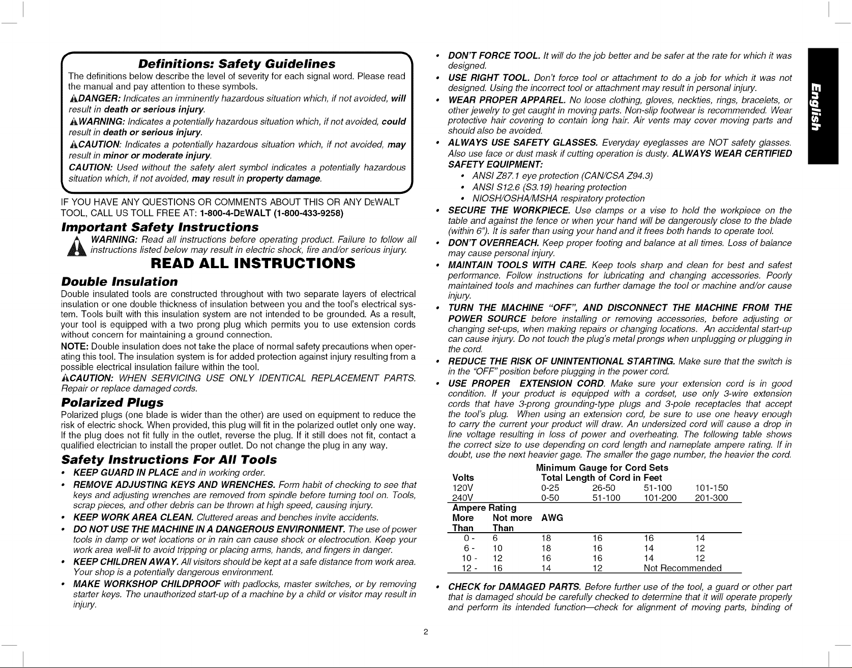
Definitions: Safety Guidelines
The definitions below describe the level of severity for each signal word. Please read
the manual and pay attention to these symbols.
i_,DANGER: Indicates an imminently hazardous situation which, if not avoided, will
result in death or serious injury.
AWARNING: Indicates a potentially hazardous situation which, if not avoided, could
result in death or serious injury.
_&CAUTION: Indicates a potentially hazardous situation which, if not avoided, may
result in minor or moderate injury.
CAUTION: Used without the safety alert symbol indicates a potentially hazardous
situation which, if not avoided, may result in property damage.
IF YOU HAVE ANY QUESTIONS OR COMMENTS ABOUT THIS OR ANY DEWALT
TOOL, CALL US TOLL FREE AT: 1-800-4-DEWALT (1-800-433-9258)
Important Safety Instructions
A ARNING: Read all instructions before operating product. Failure to follow all
instructions fisted below may result in electric shock, fire and/or serious injury.
READ ALL INSTRUCTIONS
Double Insulation
Double insulated tools are constructed throughout with two separate layers of electrical
insulation or one double thickness of insulation between you and the tool's electrical sys-
tem. Tools built with this insulation system are not intended to be grounded. As a result,
your tool is equipped with a two prong plug which permits you to use extension cords
without concern for maintaining a ground connection.
NOTE: Double insulation does not take the place of normal safety precautions when oper-
ating this tool. The insulation system is for added protection against injury resulting from a
possible electrical insulation failure within the tool.
ACAUTION: WHEN SERVICING USE ONLY IDENTICAL REPLACEMENT PARTS.
Repair or replace damaged cords.
Polarized Plugs
Polarized plugs (one blade is wider than the other) are used on equipment to reduce the
risk of electric shock. When provided, this plug will fit in the polarized outlet only one way.
If the plug does not fit fully in the outlet, reverse the plug. If it still does not fit, contact a
qualified electrician to install the proper outlet. Do not change the plug in any way.
Safety Instructions For All Tools
• KEEP GUARD IN PLACE and in working order.
• REMOVE ADJUSTING KEYS AND WRENCHES. Form habit of checking to see that
keys and adjusting wrenches are removed from spindle before turning tool on. Tools,
scrap pieces, and other debris can be thrown at high speed, causing injury.
• KEEP WORK AREA CLEAN. Cluttered areas and benches invite accidents.
• DO NOT USE THE MACHINE IN A DANGEROUS ENVIRONMENT. The use of power
tools in damp or wet locations or in rain can cause shock or electrocution. Keep your
work area well-lit to avoid tripping or placing arms, hands, and fingers in danger.
• KEEP CHILDRENAWAY. All visitors shouldbe keptata safe distance from workarea.
Your shop is a potentially dangerous environment.
• MAKE WORKSHOP CHILDPROOF with padlocks, master switches, or by removing
starter keys. The unauthorized start-up of a machine by a child or visitor may result in
injury.
• DON'T FORCE TOOL. It will do the job better and be safer at the rate for which it was
designed.
• USE RIGHT TOOL. Don't force tool or attachment to do a job for which it was not
designed. Using the incorrect tool or attachment may result in personal injury.
• WEAR PROPER APPAREL. No loose clothing, gloves, neckties, rings, bracelets, or
other jewelry to get caught in moving parts. Non-slip footwear is recommended. Wear
protective hair covering to contain long hair. Air vents may cover moving parts and
should also be avoided.
• ALWAYS USE SAFETY GLASSES. Everyday eyeglasses are NOT safety glasses.
Also use face or dust mask if cutting operation is dusty. ALWAYS WEAR CERTIFIED
SAFETY EQUIPMENT:
• ANSI Z87.1 eye protection (CAN/CSA Z94.3)
• ANSI $12.6 (S3.19) hearing protection
• NIOSH/OSHA/MSHA respiratory protection
• SECURE THE WORKPIECE. Use clamps or a vise to hold the workpiece on the
table and against the fence or when your hand will be dangerously close to the blade
(within 6"). It is safer than using your hand and it frees both hands to operate tooL
• DON'T OVERREACH. Keep proper footing and balance at all times. Loss of balance
may cause personal injury.
• MAINTAIN TOOLS WITH CARE. Keep tools sharp and clean for best and safest
performance. Follow instructions for lubricating and changing accessories. Poorly
maintained tools and machines can further damage the tool or machine and/or cause
injury.
• TURN THE MACHINE "OFF'; AND DISCONNECT THE MACHINE FROM THE
POWER SOURCE before installing or removing accessories, before adjusting or
changing set-up& when making repairs or changing locations. An accidental start-up
can cause injury. Do not touch the plug's metal prongs when unplugging or plugging in
the cord.
• REDUCE THE RISK OF UNINTENTIONAL STARTING. Make sure that the switch is
in the "OFF" position before plugging in the power cord.
• USE PROPER EXTENSION CORD. Make sure your extension cord is in good
condition. If your product is equipped with a cordset, use only 3-wire extension
cords that have 3-prong grounding-type plugs and 3-pole receptacles that accept
the tool's plug. When using an extension cord, be sure to use one heavy enough
to carry the current your product will draw. An undersized cord will cause a drop in
line voltage resulting in loss of power and overheating. The following table shows
the correct size to use depending on cord length and nameplate ampere rating. If in
doubt, use the next heavier gage. The smaller the gage number, the heavier the cord.
Volts
120V
240V
Ampere Rating
More Not more
Than Than
O- 6
6- 10
10 - 12
12 - 16
• CHECK for DAMAGED PARTS. Before further use of the tool, a guard or other part
that is damaged should be carefully checked to determine that it will operate properly
and perform its intended function--check for alignment of moving parts, binding of
Minimum Gauge for Cord Sets
Total Length of Cord in Feet
0-25 26-50 51-100 101-150
0-50 51-100 101-200 201-300
AWG
18 16 16 14
18 16 14 12
16 16 14 12
14 12 Not Recommended
Page 4

movingparts,breakageofparts,mountingandanyotherconditionsthatmayaffect
itsoperation.Aguardorotherpartthatis damagedshouldbeproperlyrepairedor
replaced.Donotusetoolffswitchdoesnotturnitonandoff.
• USE RECOMMENDED ACCESSORIES. Use only accessories that are recommended
by the manufacturer for your model Accessories that may be suitable for one tool
may be hazardous when used on another tooL Consult the instruction manual for
recommended accessories. The use of improper accessories may cause risk of injury
to persons.
• NEVER STAND ON TOOL. Serious injury could occur if the tool is tipped or if the
cutting tool is unintentionally contacted.
• NEVER LEAVE TOOL RUNNING UNATTENDED. TURN POWER OFF. Don't leave
tool until it comes to a complete stop. Serious injury can result.
• DO NOT OPERATE ELECTRIC TOOLS NEAR FLAMMABLE LIQUIDS OR IN
GASEOUS OR EXPLOSIVE ATMOSPHERES. Motors in these tools may spark and
ignite fumes.
• STAY ALERT, WATCH WHAT YOU ARE DOING, AND USE COMMON SENSE. DO
NOT USE THE MACHINE WHEN YOU ARE TIRED OR UNDER THE INFLUENCE
OF DRUGS or ALCOHOL. A moment of inattention while operating power tools may
result in injury.
Additional Safety Rules For Miter Saws
WARNING: Do not allow familiarity (gained from frequent use of your saw) to replace
safety rules. Always remember that a careless fraction of a second is sufficient to inflict
severe injury.
• DO NOT OPERATE THIS MACHINE until it is completely assembled and installed
according to the instructions. A machine incorrectly assembled can cause serious
injury.
• OBTAIN ADVICE from your supervisor, instructor, or another qualified person ff you
are not thoroughly familiar with the operation of this machine. Knowledge is safety.
• STABILITY. Make sure the miter saw is placed on a secure supporting surface and
does not slip or move during use. If the mobility kit is installed, raise the moveable
caster(s) so saw is in its stationary position.
• FOLLOW ALL WIRING CODES and recommended electrical connections to prevent
shock or electrocution. Protect electric supply line with at least a 15 ampere time-delay
fuse or a circuit breaker."
• MAKE CERTAIN the blade rotates in the correct direction. The teeth on the blade
should point in the direction of rotation as marked on the saw.
• TIGHTEN ALL CLAMP HANDLES, knobs and levers prior to operation. Loose clamps
can cause parts or the workpiece to be thrown at high speeds.
• BE SURE aft blade and clamp washers are clean, recessed sides of collars are against
blade and arbor screw is tightened securely. Loose or improper blade clamping may
result in damage to the saw and possible personal injury.
• ALWAYS USE A SHARP BLADE. Check the blade to see if it runs true and is free
from vibration. A dull or a vibrating blade can cause damage to the machine and/or
serious injury."
• DO NOT OPERATE ON ANYTHING OTHER THAN THE DESIGNATED VOLTAGE
for the saw. Overheating, damage to the tool and personal injury may occur.
• DO NOT WEDGE ANYTHING AGAINST THE FAN to hold the motor shaft. Damage
to tool and possible personal injury may occur.
• DO NOT force cutting action. Stalling or partial stalling of motor can cause damage. To
the machine or blade and/or serious injury.
• ALLOW THE MOTOR TO COME TO FULL SPEED prior to starting cut. Starting the
cut too soon may cause damage to the machine or blade and/or serious injury."
• NEVER CUT FERROUS METALS (Those with any iron or steel content) or masonry.
Either of these can cause the carbide tips to fly off the blade at high speeds causing
serious injury.
• DO NOT USE ABRASIVE WHEELS. The excessive heat and abrasive particles
generated by them may damage the saw and cause personal injury.
• NEVER have any part of your body in line with the path of the saw blade. Personal
injury will occur.
• NEVER apply blade lubricant to a running blade. Applying lubricant could cause your
hand to move into the blade resulting in serious injury.
• DO NOT place either hand in the blade area when the saw is connected to the power
source. Inadvertent blade activation may result in serious injury.
• DO NOT PERFORM FREE-HAND OPERATIONS (workpiece not supported by table
and fence). Hold the work firmly against the fence and table. Free-hand operations on
a miter saw could cause the workpiece to be thrown at high speeds, causing serious
injury.
• NEVER REACH AROUND or behind the saw blade. A blade can cause serious
injury.
• DO NOT reach underneath the saw unless it is unplugged and turned off. Contact with
saw blade may cause personal injury.
• SECURE THE MACHINE TO A STABLE SUPPORTING SURFACE. Vibration can
possibly cause the machine to slide, walk, or tip over, causing serious injury.
• USE ONLY CROSSCUT SAW BLADES recommended for miter saws. For best
results, use only zero-degree or negative hook angles when using carbide-tipped
blades. Do not use blades with deep gullets. These can deflect and contact the guard,
and can cause damage to the machine and/or serious injury.
• USE ONLY BLADES OF THE CORRECT SIZE AND TYPE specified for this tool to
prevent damage to the machine and/or serious injury.
• INSPECT BLADE FOR CRACKS or other damage prior to operation. A cracked or
damaged blade can come apart and pieces can be thrown at high speeds, causing
serious injury. Replace cracked or damaged blades immediately.
• CLEAN THE BLADE AND BLADE FLANGES prior to operation. Cleaning the blade
and flanges allows you to check for any damage to the blade or flanges. A cracked or
damaged blade or flange can come apart and pieces can be thrown at high speeds,
causing serious injury.
• DO NOT use lubricants or cleaners (particularly spray or aerosol) in the vicinity of the
plastic guard. The polycarbonate material used in the guard is subject to attack by
certain chemicals.
• AL WAYS USE THE KERF PLA TE AND REPLACE THIS PLATE WHEN DAMAGED.
Small chip accumulation under the saw may interfere with the saw blade or may cause
instability of workpiece when cutting.
• USE ONLY BLADE FLANGES specified for this tool to prevent damage to the machine
and/or serious injury.
• CLEAN THE MOTOR AIR SLOTS of chips and sawdust. Clogged motor air slots can
cause the machine to overheat, damaging the machine and possibly causing a short
which could cause serious injury.
• KEEP ARMS, HANDS, AND FINGERS away from the blade to prevent severe cuts.
Clamp all workpieces that would cause your hand to be within 6" of the saw blade.
• NEVER LOCK THE SWITCH IN THE "ON" position. Severe personal injury may
result.
Page 5
• TURN OFF THE MACHINE and allow the blade to come to a complete stop before
raising the arm and prior to cleaning the blade area, removing debris in the path of the
blade, before servicing or adjusting tool A moving blade can cause serious injury.
• PROPERLY SUPPORT LONG OR WIDE WORKPIECES. Loss of control of the
workpiece can cause injury.
• NEVER cross arms in front of blade while using tool Always make a dry run
(unpowered) before making a finish cut so that you can check the path of the blade or
severe personal injury may result.
• ADDITIONAL INFORMATION regarding the safe and proper operation of power
tools (i.e. a safety video) is available from the Power Tool Institute, 1300 Sumner
Avenue, Cleveland, OH 44115-2851 (www.powertoolinstitute.com). Information is also
available from the National Safety Council, 1121 Spring Lake Drive, Itasca, IL 60143-
3201. Please refer to the American National Standards Institute ANSI 01.1 Safety
Requirements for Woodworking Machines and the U.S. Department of Labor OSHA
1910.213 Regulations.
J&CAUTION: Do not connect unit to electrical power source until complete instructions are
read and understood.
_ WARNING: Always wear proper personal hearing protection that conforms to
ANSI $12.6 ($3.19) during use. Under some conditions and duration of use, noise from
this product may contribute to hearing loss.
WARNING: NEVER MAKE ANY CUT UNLESS THE MATERIAL IS SECURED ON
THE TABLE AND AGAINST THE FENCE.
_ WARNING: Some dust created by power sanding, sawing, grinding, drilling, and other
construction activities contains chemicals known to cause cancer, birth defects or other
reproductive harm. Some examples of these chemicals are:
• lead from lead-based paints,
• crystalline silica from bricks and cement and other masonry products, and
• arsenic and chromium from chemically-treated lumber (CCA).
Your risk from these exposures varies, depending on how often you do this type of work.
To reduce your exposure to these chemicals: work in a well ventilated area, and work
with approved safety equipment, such as those dust masks that are specially designed to
filter out microscopic particles.
• Avoid prolonged contact with dust from power sanding, sawing, grinding,
drilling, and other construction activities. Wear protective clothing and wash
exposed areas with soap and water. Allowing dust to get into your mouth, eyes,
or lay on the skin may promote absorption of harmful chemicals.
WARNING: Use of this tool can generate and/or disburse dust, which may cause
serious and permanent respiratory or other injury. Always use NIOSH/OSHA approved
respiratory protection appropriate for the dust exposure. Direct particles away from face
and body.
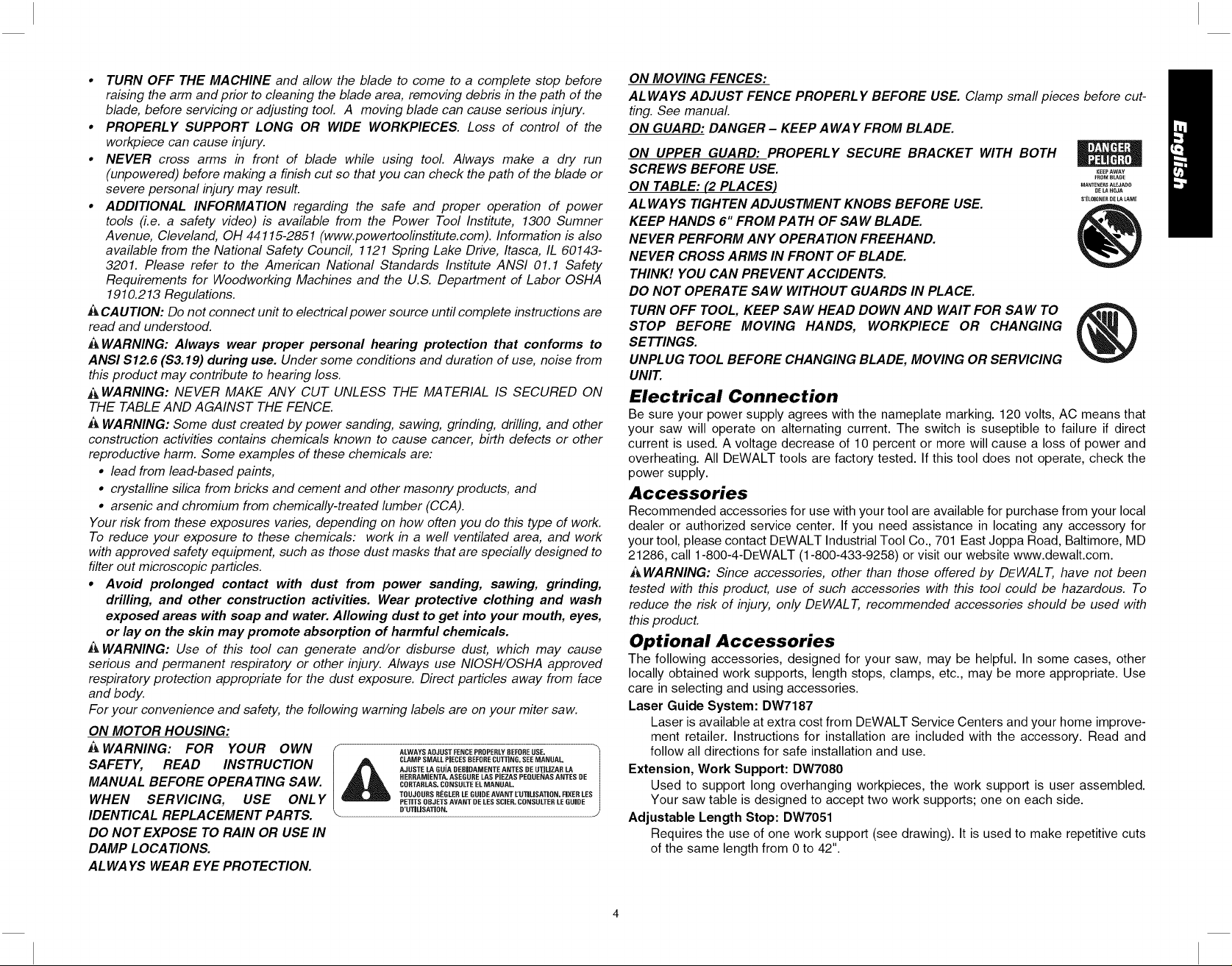
For your convenience and safety, the following warning labels are on your miter saw.
ON MOTOR HOUSING:
A WARNING: FOR YOUR OWN
SAFETY, READ INSTRUCTION
MANUAL BEFORE OPERA TING SAW.
WHEN SERVICING, USE ONLY
IDENTICAL REPLACEMENT PARTS.
I_ ALWAYS ADJUSTFENCE PROPERLYBEFOREUSE.
CLAMP SMALL PIECES BEFORECUTTING. SEE MANUAL
AJUSTE LA GUiA DEBiDAMENTE ANTES DE UTiLiZAR LA
HERRAMiENTA. ASEGURE LAS PJEZAS PEQUENAS ANTES DE
CORTARLAS. CONSULTE ELMANUAL.
TOUJOURS REGLERLE GUIDE AVANT EUTILiSATION. FIXER LES
PETiTS OBJETS AVANT DE LESSCiER. CONSULTER LE GUIDE
O'UTJLiSATiON. /
DO NOT EXPOSE TO RAIN OR USE IN
DAMP LOCATIONS.
ALWAYS WEAR EYE PROTECTION.
ON MOVING FENCES:
AL WAYS ADJUST FENCE PROPERLY BEFORE USE. Clamp small pieces before cut-
ting. See manual
ON GUARD: DANGER - KEEP A WAY FROM BLADE.
ON UPPER GUARD: PROPERLY SECURE BRACKET WITH BOTH
SCREWS BEFORE USE.
ON TABLE: (2 PLACES)
AL WAYS TIGHTEN ADJUSTMENT KNOBS BEFORE USE.
_EEPAWAY
FROMBL_OE
MANTENE_SALEJADO
OE_AHOJA
S'ELOIUNERDELALA_qE
KEEP HANDS 6" FROM PATH OF SAW BLADE.
NEVER PERFORM ANY OPERA TION FREEHAND.
NEVER CROSS ARMS IN FRONT OF BLADE.
THINK! YOU CAN PREVENT ACCIDENTS.
DO NOT OPERATE SAW WITHOUT GUARDS IN PLACE.
TURN OFF TOOL, KEEP SAW HEAD DOWN AND WAIT FOR SAW TO
STOP BEFORE MOVING HANDS, WORKPIECE OR CHANGING
SETTINGS.
UNPLUG TOOL BEFORE CHANGING BLADE, MOVING OR SERVICING
UNIT.
Electrical Connection
Be sure your power supply agrees with the nameplate marking. 120 volts, AC means that
your saw will operate on alternating current. The switch is suseptible to failure if direct
current is used. A voltage decrease of 10 percent or more will cause a loss of power and
overheating. All DEWALT tools are factory tested. If this tool does not operate, check the
power supply.
Accessories
Recommended accessories for use with your tool are available for purchase from your local
dealer or authorized service center. If you need assistance in locating any accessory for
your tool, please contact DEWALT Industrial Tool Co., 701 East Joppa Road, Baltimore, MD
21286, call 1-800-4-DEWALT (1-800-433-9258) or visit our website www.dewalt.com.
_&WARNING: Since accessories, other than those offered by DEWAL T, have not been
tested with this product, use of such accessories with this tool could be hazardous. To
reduce the risk of injury, only DEWAL T, recommended accessories should be used with
this product.
Optional Accessories
The following accessories, designed for your saw, may be helpful. In some cases, other
locally obtained work supports, length stops, clamps, etc., may be more appropriate. Use
care in selecting and using accessories.
Laser Guide System: DW7187
Laser is available at extra cost from DEWALT Service Centers and your home improve-
ment retailer. Instructions for installation are included with the accessory. Read and
follow all directions for safe installation and use.
Extension, Work Support: DW7080
Used to support long overhanging workpieces, the work support is user assembled.
Your saw table is designed to accept two work supports; one on each side.
Adjustable Length Stop: DW7051
Requires the use of one work support (see drawing). It is used to make repetitive cuts
of the same length from 0 to 42".
Page 6
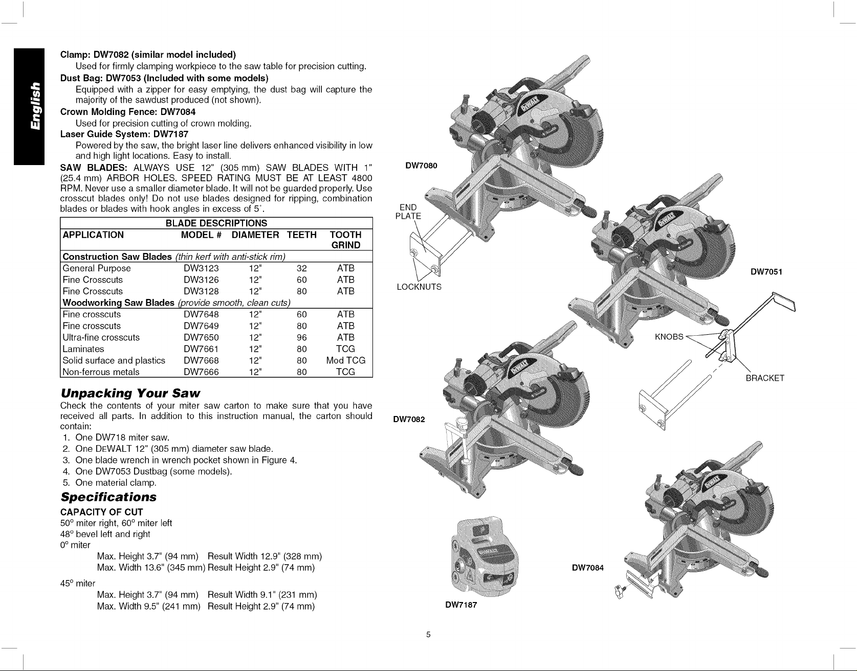
Clamp:DW7082(similarmodelincluded)
Usedforfirmlyclampingworkpiecetothesawtableforprecisioncutting.
DustBag:DW7053(Includedwithsomemodels)
Equippedwithazipperforeasyemptying,thedustbagwillcapturethe
majorityofthesawdustproduced(notshown).
CrownMoldingFence:DW7084
Usedforprecisioncuttingofcrownmolding.
LaserGuideSystem:DW7187
Poweredbythesaw,thebrightlaserlinedeliversenhancedvisibilityinlow
andhighlightlocations.Easytoinstall.
SAWBLADES:ALWAYSUSE12"(305mm)SAWBLADESWITH1"
(25.4mm)ARBORHOLES.SPEEDRATINGMUSTBEATLEAST4800
RPM.Neveruseasmallerdiameterblade.Itwillnotbeguardedproperly.Use
crosscutbladesonly!Donotusebladesdesignedforripping,combination
bladesorbladeswithhookanglesinexcessof5°.
BLADEDESCRIPTIONS
APPLICATION MODEL# DIAMETERTEETH TOOTH
GRIND
ConstructionSawBlades (thin kerf with anti-stick rim)
General Purpose DW3123 12" 32 ATB
Fine Crosscuts DW3126 12" 60 ATB
Fine Crosscuts DW3128 12" 80 ATB
Woodworkinq Saw Blades (provide smooth, clean cuts)
Fine crosscuts DW7648 12" 60 ATB
Fine crosscuts DW7649 12" 80 ATB
Ultra-fine crosscuts DW7650 12" 96 ATB
Laminates DW7661 12" 80 TCG
Solid surface and plastics DW7668 12" 80 Mod TCG
Non-ferrous metals DW7666 12" 80 TCG
Unpacking Your Saw
Check the contents of your miter saw carton to make sure that you have
received all parts. In addition to this instruction manual, the carton should
contain:
1. One DW718 miter saw.
2. One DEWALT 12" (305 mm) diameter saw blade.
3. One blade wrench in wrench pocket shown in Figure 4.
4. One DW7053 Dustbag (some models).
5. One material clamp.
Specifications
CAPACITY OF CUT
50° miter right, 60° miter left
48° bevel left and right
0° miter
Max. Height 3.7" (94 mm) Result Width 12.9" (328 mm)
Max. Width 13.6" (345 mm) Result Height 2.9" (74 mm)
45° miter
Max. Height 3.7" (94 mm) Result Width 9.1" (231 mm)
Max. Width 9.5" (241 mm) Result Height 2.9" (74 mm)
DW7080
END
PLATE
DW7051
LOCKNUTS
BRACKET
DW7082
DW7084
DW7187
Page 7
45° bevel - Left
Max. Height 2.4" (61 mm) Result Width 12.9" (328 mm)
Max. Width 13.6" (345 mm) Result Height 1.9" (48 mm)
45° bevel - Right
Max. Height 1.7" (43 mm) Result Width 12.9" (328 mm)
Max. Width 13.6" (345 mm) Result Height 1.1" (28 mm)
Your saw is capable of cutting baseboard moldings 0.8" (20 mm) thick by 6.5" (165 mm)
tall on a 45° right or left miter.
NOTE: Your saw is capable of cutting the following once a special setup procedure is fol-
lowed (see Special Cuts).
0° miter height 1.5 width 16.1
45° miter height 1.5 width 11.7
DRIVE
120 Volt Motor
1600 Watts In 15 Amp Motor
3600 RPM Cut Helical Gears
Multi-V Belt Roller Bearings
Automatic Electric Brake Carbide Blade
Familia riza tion
Your miter saw is fully assembled in the carton. Open the
box and lift the saw out by the convenient carrying handle, FIG. 1
as shown in Figure 1.
Place the saw on a smooth, flat surface such as a work-
bench or strong table.
Examine the two figures on page 7 to become familiar with
the saw and its various parts. The section on adjustments
will refer to these terms and you must know what and
where the parts are.
Press down lightly on the operating handle and pull out the lock FIG. 2
down pin. Gently release the downward pressure and hold the arm
allowing it to rise to its full height. Use the lock down pin when car-
rying the saw from one place to another. Always use the carrying
handle to transport the saw or the hand indentations shown in
Figure. 2.
Bench Mounting-
Holes are provided in all 4 feet to facilitate bench mounting, as
shown in Figure 4. (Two different sized holes are provided to
accommodate different sizes of screws. Use either hole, it is not
necessary to use both.) Always mount your saw firmly to a stable
surface to prevent movement. To enhance the tool's portability, it
can be mounted to a piece of 1/2" (12.7 mm) or thicker plywood
which can then be clamped to your work support or moved to other job sites and rec-
lamped.
NOTE: If you elect to mount your saw to a piece of plywood, make sure that the mounting
screws don't protrude from the bottom of the wood. The plywood must sit flush on the work
support. When clamping the saw to any work surface, clamp only on the clamping bosses
where the mounting screw holes are located. Clamping at any other point will surely inter-
fere with the proper operation of the saw.
,&CAUTION: To prevent binding and inaccuracy, be sure the mounting surface is not
warped or otherwise uneven, ff the saw rocks on the surface place a thin piece of material
under one saw foot until the saw sits firmly on the mounting surface.
IMPORTANT SAFETY INSTRUCTIONS
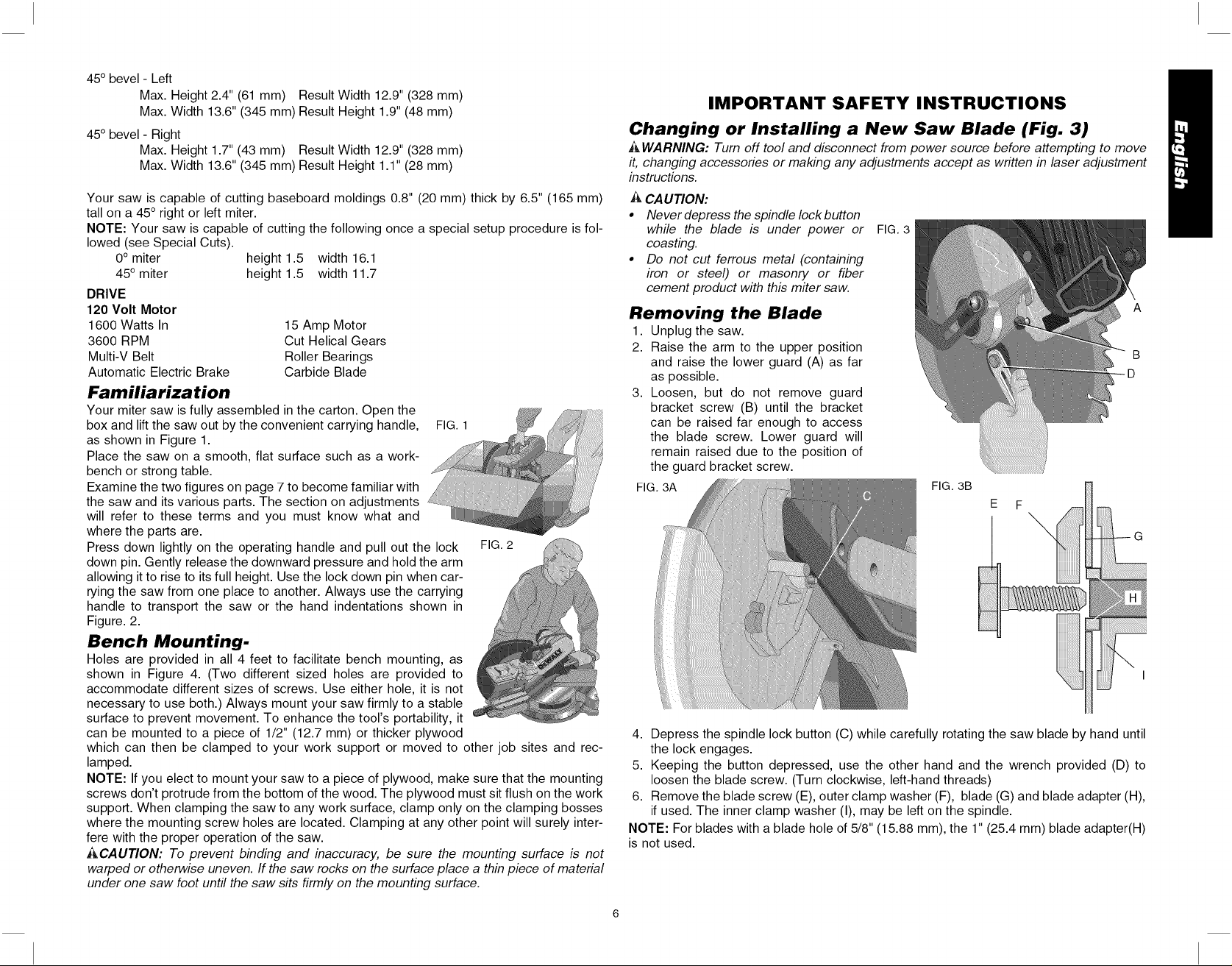
Changing or Installing a New Saw Blade (Fig. 3)
h&WARNING: Turn off tool and disconnect from power source before attempting to move
it, changing accessories or making any adjustments accept as written in laser adjustment
instructions.
CAUTION:
• Never depress the spindle lock button
while the blade is under power or
coasting.
• Do not cut ferrous metal (containing
iron or steel) or masonry or fiber
cement product with this miter saw.
FIG. 3
Removing the Blade
1. Unplug the saw.
2. Raise the arm to the upper position
and raise the lower guard (A) as far
as possible.
3. Loosen, but do not remove guard
bracket screw (B) until the bracket
can be raised far enough to access
the blade screw. Lower guard will
remain raised due to the position of
the guard bracket screw.
FIG. 3A FIG. 3B
E F
4. Depress the spindle lock button (C) while carefully rotating the saw blade by hand until
the lock engages.
5. Keeping the button depressed, use the other hand and the wrench provided (D) to
loosen the blade screw. (Turn clockwise, left-hand threads)
6. Remove the blade screw (E), outer clamp washer (F), blade (G) and blade adapter (H),
if used. The inner clamp washer (I), may be left on the spindle.
NOTE: For blades with a blade hole of 5/8" (15.88 mm), the 1" (25.4 mm) blade adapter(H)
is not used.
D
B
G
Page 8
BEVEL
LOCK
HANDLE
RAILLOCK
KNOB
RAIL SET
SCREW
ADJUSTMENT
HOUSING
LIFTING
HANDLE
MOTOR
MOTOR
BEVEL LATCH
LEVER
(one each side)
BEVEL SCALE
(one each
side)
LOCK
BLADE
PIN
WRENCH
FENCE
ADJUSTMENT
KNOB
(one each side)
TABLE
MITER
SCALE
MITER LATCH MITER LOCK
OVERRIDE HANDLE
BENCH MOUNTING HOLES
KERF
PLATE
MITER LATCH
BUTTON
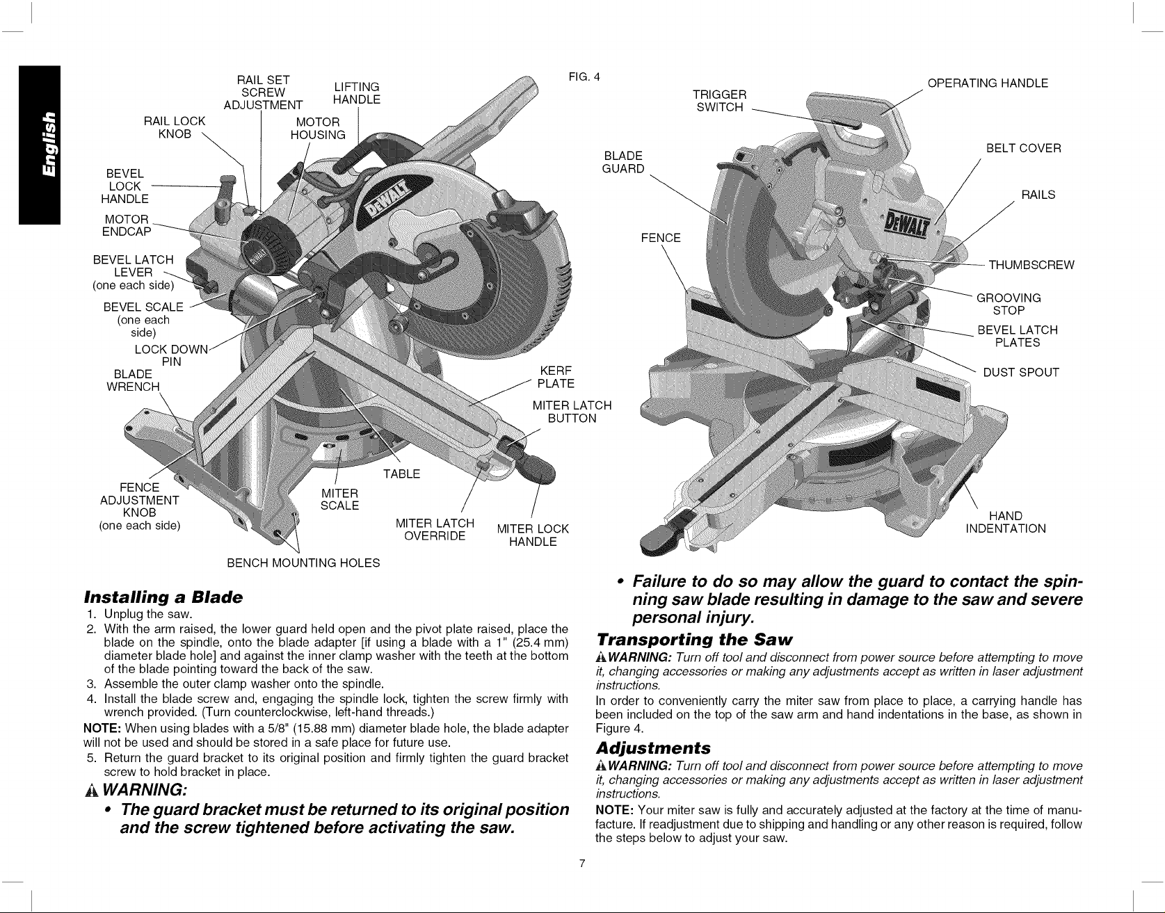
Installing a Blade
1. Unplug the saw.
2. With the arm raised, the lower guard held open and the pivot plate raised, place the
blade on the spindle, onto the blade adapter [if using a blade with a 1" (25.4 mm)
diameter blade hole] and against the inner clamp washer with the teeth at the bottom
of the blade pointing toward the back of the saw.
3. Assemble the outer clamp washer onto the spindle.
4. Install the blade screw and, engaging the spindle lock, tighten the screw firmly with
wrench provided. (Turn counterclockwise, left-hand threads.)
NOTE: When using blades with a 5/8" (15.88 mm) diameter blade hole, the blade adapter
will not be used and should be stored in a safe place for future use.
5. Return the guard bracket to its original position and firmly tighten the guard bracket
screw to hold bracket in place.
WARNING:
• The guard bracket must be returned to its original position
and the screw tightened before activating the saw.
FIG. 4
TRIGGER
SWITCH
BLADE
OPERATING HANDLE
BELT COVER
GUARD
FENCE
THUMBSCREW
GROOVING
STOP
BEVEL LATCH
PLATES
DUST SPOUT
HAND
INDENTATION
• Failure to do so may allow the guard to contact the spin-
ning saw blade resulting in damage to the saw and severe
personal injury.
Transporting the Saw
A WARNING: Turn off tool and disconnect from power source before attempting to move
it, changing accessories or making any adjustments accept as written in laser adjustment
instructions.
In order to conveniently carry the miter saw from place to place, a carrying handle has
been included on the top of the saw arm and hand indentations in the base, as shown in
Figure 4.
Adjustments
A WARNING: Turn off tool and disconnect from power source before attempting to move
it, changing accessories or making any adjustments accept as written in laser adjustment
instructions.
NOTE: Your miter saw is fully and accurately adjusted at the factory at the time of manu-
facture. If readjustment due to shipping and handling or any other reason is required, follow
the steps below to adjust your saw.
RAILS
Page 9
Oncemade,theseadjustmentsshouldremainaccurate.
Takealittletimenowtofollowthesedirectionscarefullyto
maintaintheaccuracyofwhichyoursawiscapable.
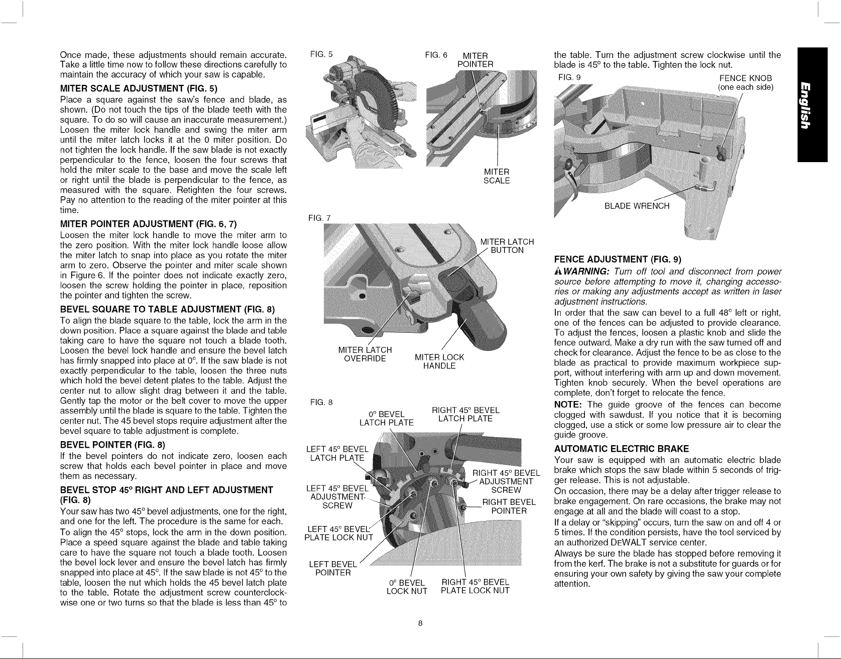
MITERSCALEADJUSTMENT (FIG. 5)
Place a square against the saw's fence and blade, as
shown. (Do not touch the tips of the blade teeth with the
square. To do so will cause an inaccurate measurement.)
Loosen the miter lock handle and swing the miter arm
until the miter latch locks it at the 0 miter position. Do
not tighten the lock handle. If the saw blade is not exactly
perpendicular to the fence, loosen the four screws that
hold the miter scale to the base and move the scale left
or right until the blade is perpendicular to the fence, as
measured with the square. Retighten the four screws.
Pay no attention to the reading of the miter pointer at this
time.
MITER POINTER ADJUSTMENT (FIG. 6, 7)
Loosen the miter lock handle to move the miter arm to
the zero position. With the miter lock handle loose allow
the miter latch to snap into place as you rotate the miter
arm to zero. Observe the pointer and miter scale shown
in Figure 6. If the pointer does not indicate exactly zero,
loosen the screw holding the pointer in place, reposition
the pointer and tighten the screw.
BEVEL SQUARE TO TABLE ADJUSTMENT (FIG. 8)
To align the blade square to the table, lock the arm in the
down position. Place a square against the blade and table
taking care to have the square not touch a blade tooth.
Loosen the bevel lock handle and ensure the bevel latch
has firmly snapped into place at 0°. If the saw blade is not
exactly perpendicular to the table, loosen the three nuts
which hold the bevel detent plates to the table. Adjust the
center nut to allow slight drag between it and the table.
Gently tap the motor or the belt cover to move the upper
assembly until the blade is square to the table. Tighten the
center nut. The 45 bevel stops require adjustment after the
bevel square to table adjustment is complete.
BEVEL POINTER (FIG. 8)
If the bevel pointers do not indicate zero, loosen each
screw that holds each bevel pointer in place and move
them as necessary.
BEVEL STOP 45° RIGHT AND LEFT ADJUSTMENT
(FIG. 8)
Your saw has two 45°bevel adjustments, one for the right,
and one for the left. The procedure is the same for each.
To align the 45° stops, lock the arm in the down position.
Place a speed square against the blade and table taking
care to have the square not touch a blade tooth. Loosen
the bevel lock lever and ensure the bevel latch has firmly
snapped into place at 45°. If the saw blade is not 45° to the
table, loosen the nut which holds the 45 bevel latch plate
to the table. Rotate the adjustment screw counterclock-
wise one or two turns so that the blade is less than 45° to
FIG. 5
FIG. 7
MITER LATCH
OVERRIDE
FIG. 8
LATCH PLATE
LEFT 45o BEVEL
LATCH PLATE
LEFT 450
ADJUSTMENT-
SCREW
LEFT 450 BEVEL "/
PLATE LOCK NUT
LEFT BEVEL
POINTER
0° BEVEL
0° BEVEL
LOCK NUT
FIG. 6 MITER
MITER LOCK
HANDLE
RIGHT 450 BEVEL
LATCH PLATE
RIGHT 450 BEVEL
PLATE LOCK NUT
POINTER
MITER
SCALE
MITER LATCH
BUTTON
RIGHT 450 BEVEL
SCREW
RIGHT BEVEL
POINTER
the table. Turn the adjustment screw clockwise until the
blade is 45° to the table. Tighten the lock nut.
FIG.9 FENCE KNOB
(one each side)
BLADE WRENCH
FENCE ADJUSTMENT (FIG. 9)
i_ WARNING: Turn off tool and disconnect from power
source before attempting to move it, changing accesso-
ries or making any adjustments accept as written in laser
adjustment instructions.
In order that the saw can bevel to a full 48° left or right,
one of the fences can be adjusted to provide clearance.
To adjust the fences, loosen a plastic knob and slide the
fence outward. Make a dry run with the saw turned off and
check for clearance. Adjust the fence to be as close to the
blade as practical to provide maximum workpiece sup-
port, without interfering with arm up and down movement.
Tighten knob securely. When the bevel operations are
complete, don't forget to relocate the fence.
NOTE: The guide groove of the fences can become
clogged with sawdust. If you notice that it is becoming
clogged, use a stick or some low pressure air to clear the
guide groove.
AUTOMATIC ELECTRIC BRAKE
Your saw is equipped with an automatic electric blade
brake which stops the saw blade within 5 seconds of trig-
ger release. This is not adjustable.
On occasion, there may be a delay after trigger release to
brake engagement. On rare occasions, the brake may not
engage at all and the blade will coast to a stop.
If a delay or "skipping" occurs, turn the saw on and off 4 or
5times. If the condition persists, have the tool serviced by
an authorized DEWALT service center.
Always be sure the blade has stopped before removing it
from the ken<.The brake is not a substitute for guards or for
ensuring your own safety by giving the saw your complete
attention.
Page 10
GUARD ACTUATION AND VISIBILITY
The blade guard on your saw has been designed to auto-
matically raise when the arm is brought down and to lower
over the blade when the arm is raised.
The guard can be raised by hand when installing or
removing saw blades or for inspection of the saw. NEVER
RAISE THE BLADE GUARD MANUALLY UNLESS THE
SAW IS TURNED OFF.
NOTE: Certain special cuts of large material will require
that you manually raise the guard. See page 13.
The front section of the guard is Iouvered for visibility
while cutting. Although the louvers dramatically reduce
flying debris, they are openings in the guard and safety
glasses should be worn at all times when viewing
through the louvers.
KERF PLATE ADJUSTMENT
To adjust the kerf plates, loosen the screws holding the
kerr plates in place. Adjust so that the kerr plates are
as close as possible without interfering with the blade's
movement.
RAIL GUIDE ADJUSTMENT
Periodically check the rails for any play or clearance. The
right rail can be adjusted with the set screw shown in
Figure 4. To reduce clearance, use a 4 mm hex wrench
and rotate the set screw clockwise gradually while sliding
the saw head back and forth. Reduce play while maintain-
ing minimum slide force.
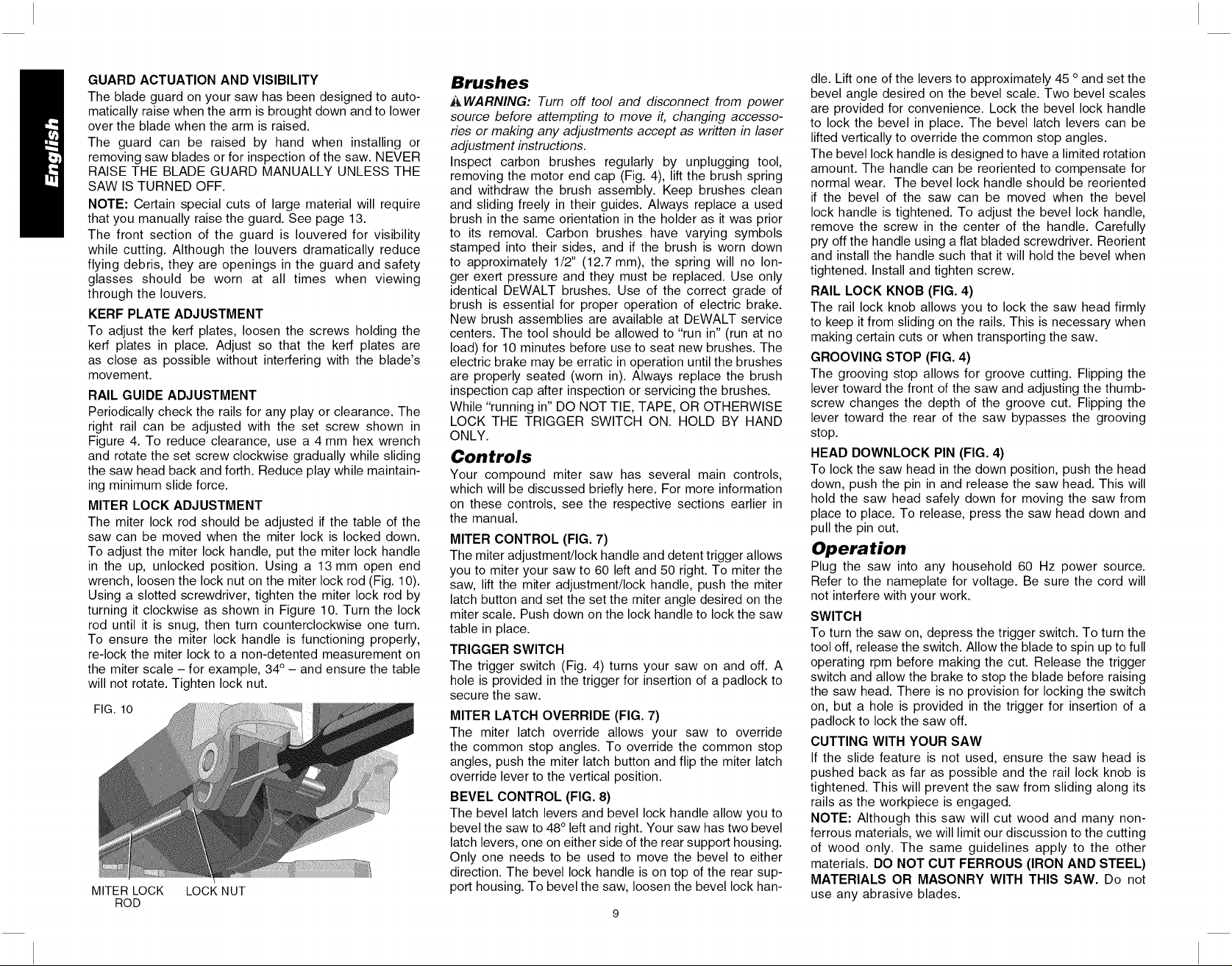
MITER LOCK ADJUSTMENT
The miter lock rod should be adjusted if the table of the
saw can be moved when the miter lock is locked down.
To adjust the miter lock handle, put the miter lock handle
in the up, unlocked position. Using a 13 mm open end
wrench, loosen the lock nut on the miter lock rod (Fig. 10).
Using a slotted screwdriver, tighten the miter lock rod by
turning it clockwise as shown in Figure 10. Turn the lock
rod until it is snug, then turn counterclockwise one turn.
To ensure the miter lock handle is functioning properly,
re-lock the miter lock to a non-detented measurement on
the miter scale - for example, 34° - and ensure the table
will not rotate. Tighten lock nut.
FIG, 10
MITER LOCK LOCK NUT
ROD
Brushes
A WARNING: Turn off tool and disconnect from power
source before attempting to move it, changing accesso-
ries or making any adjustments accept as written in laser
adjustment instructions.
Inspect carbon brushes regularly by unplugging tool,
removing the motor end cap (Fig. 4), lift the brush spring
and withdraw the brush assembly. Keep brushes clean
and sliding freely in their guides. Always replace a used
brush in the same orientation in the holder as it was prior
to its removal. Carbon brushes have varying symbols
stamped into their sides, and if the brush is worn down
to approximately 1/2" (12.7 mm), the spring will no lon-
ger exert pressure and they must be replaced. Use only
identical DEWALT brushes. Use of the correct grade of
brush is essential for proper operation of electric brake.
New brush assemblies are available at DEWALT service
centers. The tool should be allowed to "run in" (run at no
load) for 10 minutes before use to seat new brushes. The
electric brake may be erratic in operation until the brushes
are properly seated (worn in). Always replace the brush
inspection cap after inspection or servicing the brushes.
While "running in" DO NOT TIE, TAPE, OR OTHERWISE
LOCK THE TRIGGER SWITCH ON. HOLD BY HAND
ONLY.
Controls
Your compound miter saw has several main controls,
which will be discussed briefly here. For more information
on these controls, see the respective sections earlier in
the manual.
MITER CONTROL (FIG. 7)
The miter adjustment/lock handle and detent trigger allows
you to miter your saw to 60 left and 50 right. To miter the
saw, lift the miter adjustment/lock handle, push the miter
latch button and set the set the miter angle desired on the
miter scale. Push down on the lock handle to lock the saw
table in place.
TRIGGER SWITCH
The trigger switch (Fig. 4) turns your saw on and off. A
hole is provided in the trigger for insertion of a padlock to
secure the saw.
MITER LATCH OVERRIDE (FIG. 7)
The miter latch override allows your saw to override
the common stop angles. To override the common stop
angles, push the miter latch button and flip the miter latch
override lever to the vertical position.
BEVEL CONTROL (FIG. 8)
The bevel latch levers and bevel lock handle allow you to
bevel the saw to 48° left and right. Your saw has two bevel
latch levers, one on either side of the rear support housing.
Only one needs to be used to move the bevel to either
direction. The bevel lock handle is on top of the rear sup-
port housing. To bevel the saw, loosen the bevel lock han-
die. Lift one of the levers to approximately 45 oand set the
bevel angle desired on the bevel scale. Two bevel scales
are provided for convenience. Lock the bevel lock handle
to lock the bevel in place. The bevel latch levers can be
lifted vertically to override the common stop angles.
The bevel lock handle is designed to have a limited rotation
amount. The handle can be reoriented to compensate for
normal wear. The bevel lock handle should be reoriented
if the bevel of the saw can be moved when the bevel
lock handle is tightened. To adjust the bevel lock handle,
remove the screw in the center of the handle. Carefully
pry off the handle using a flat bladed screwdriver. Reorient
and install the handle such that it will hold the bevel when
tightened. Install and tighten screw.
RAIL LOCK KNOB (FIG. 4)
The rail lock knob allows you to lock the saw head firmly
to keep it from sliding on the rails. This is necessary when
making certain cuts or when transporting the saw.
GROOVING STOP (FIG. 4)
The grooving stop allows for groove cutting. Flipping the
lever toward the front of the saw and adjusting the thumb-
screw changes the depth of the groove cut. Flipping the
lever toward the rear of the saw bypasses the grooving
stop.
HEAD DOWNLOCK PIN (FIG. 4)
To lock the saw head in the down position, push the head
down, push the pin in and release the saw head. This will
hold the saw head safely down for moving the saw from
place to place. To release, press the saw head down and
pull the pin out.
Operation
Plug the saw into any household 60 Hz power source.
Refer to the nameplate for voltage. Be sure the cord will
not interfere with your work.
SWITCH
To turn the saw on, depress the trigger switch. To turn the
tool off, release the switch. Allow the blade to spin up to full
operating rpm before making the cut. Release the trigger
switch and allow the brake to stop the blade before raising
the saw head. There is no provision for locking the switch
on, but a hole is provided in the trigger for insertion of a
padlock to lock the saw off.
CUTTING WITH YOUR SAW
If the slide feature is not used, ensure the saw head is
pushed back as far as possible and the rail lock knob is
tightened. This will prevent the saw from sliding along its
rails as the workpiece is engaged.
NOTE: Although this saw will cut wood and many non-
ferrous materials, we will limit our discussion to the cutting
of wood only. The same guidelines apply to the other
materials. DO NOT CUT FERROUS (IRON AND STEEL)
MATERIALS OR MASONRY WITH THIS SAW. Do not
use any abrasive blades.
Page 11
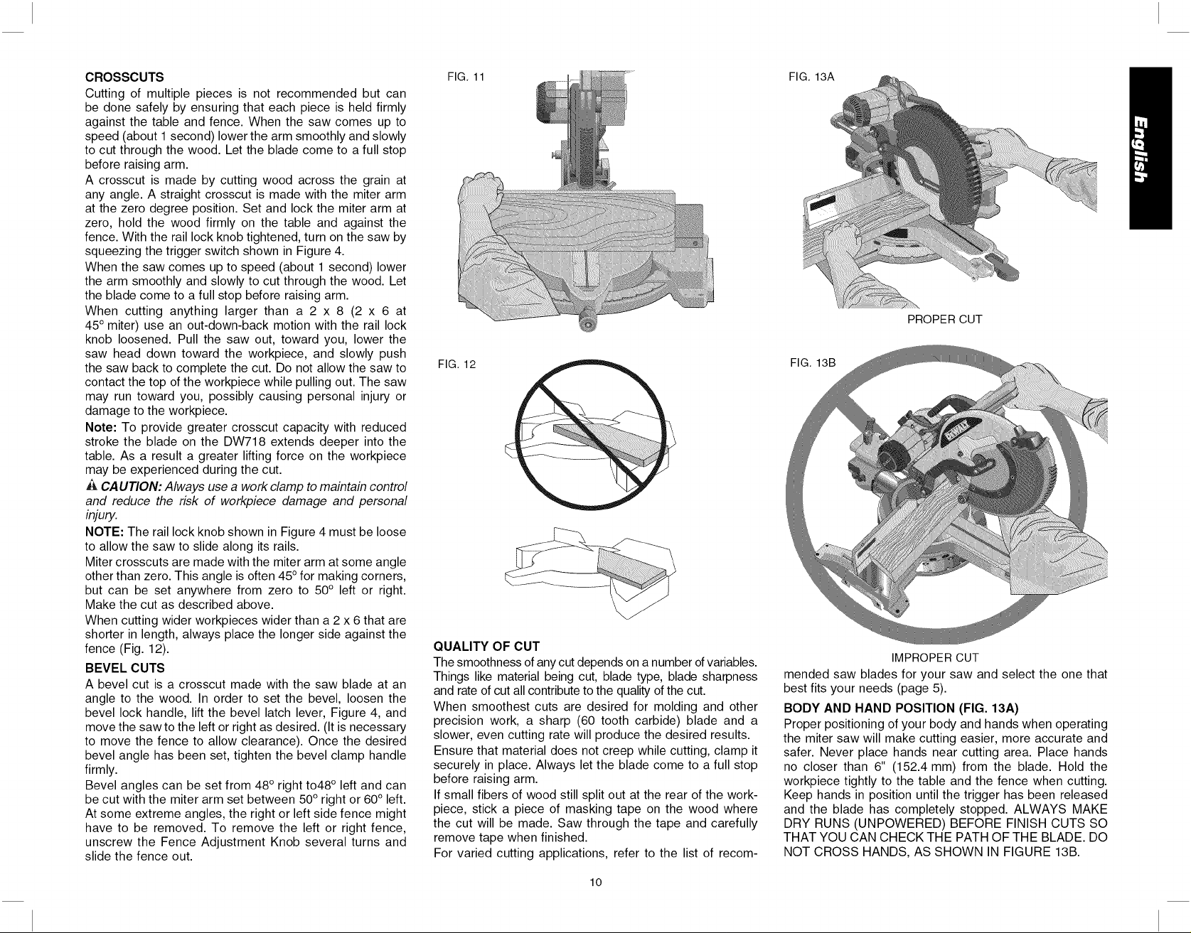
CROSSCUTS
Cuttingof multiplepiecesis notrecommendedbutcan
bedonesafelybyensuringthateachpieceisheldfirmly
againstthetableandfence.Whenthesawcomesupto
speed(about1second)lowerthearmsmoothlyandslowly
tocutthroughthewood.Letthebladecometoafullstop
beforeraisingarm.
Acrosscutismadebycuttingwoodacrossthegrainat
anyangle.Astraightcrosscutismadewiththemiterarm
atthezerodegreeposition.Setandlockthemiterarmat
zero,holdthewoodfirmlyonthetableandagainstthe
fence.Withtheraillockknobtightened,turnonthesawby
squeezingthetriggerswitchshowninFigure4.
Whenthesawcomesuptospeed(about1second)lower
thearmsmoothlyandslowlytocutthroughthewood.Let
thebladecometoafullstopbeforeraisingarm.
Whencuttinganythinglargerthana2 x 8 (2 x 6 at
45°miter)useanout-down-backmotionwiththeraillock
knobloosened.Pullthesawout,towardyou,lowerthe
sawheaddowntowardtheworkpiece,andslowlypush
thesawbacktocompletethecut.Donotallowthesawto
contactthetopoftheworkpiecewhilepullingout.Thesaw
mayruntowardyou,possiblycausingpersonalinjuryor
damagetotheworkpiece.
Note:Toprovidegreatercrosscutcapacitywithreduced
strokethebladeontheDW718extendsdeeperintothe
table.Asaresultagreaterliftingforceontheworkpiece
maybeexperiencedduringthecut.
CAUTION: Always use a work clamp to maintain control
and reduce the risk of workpiece damage and personal
injury.
NOTE: The rail lock knob shown in Figure 4 must be loose
to allow the saw to slide along its rails.
Miter crosscuts are made with the miter arm at some angle
other than zero. This angle is often 45° for making corners,
but can be set anywhere from zero to 50° left or right.
Make the cut as described above.
When cutting wider workpieces wider than a 2 x 6 that are
shorter in length, always place the longer side against the
fence (Fig. 12).
BEVEL CUTS
A bevel cut is a crosscut made with the saw blade at an
angle to the wood. In order to set the bevel, loosen the
bevel lock handle, lift the bevel latch lever, Figure 4, and
move the sawto the left or right as desired. (It is necessary
to move the fence to allow clearance). Once the desired
bevel angle has been set, tighten the bevel clamp handle
firmly.
Bevel angles can be set from 48° right to48 ° left and can
be cut with the miter arm set between 50° right or 60° left.
At some extreme angles, the right or left side fence might
have to be removed. To remove the left or right fence,
unscrew the Fence Adjustment Knob several turns and
slide the fence out.
FIG. 11
FIG. 12
QUALITY OF CUT
The smoothness of any cut depends on a number of variables.
Things like material being cut, blade type, blade sharpness
and rate of cut all contribute to the quality of the cut.
When smoothest cuts are desired for molding and other
precision work, a sharp (60 tooth carbide) blade and a
slower, even cutting rate will produce the desired results.
Ensure that material does not creep while cutting, clamp it
securely in place. Always let the blade come to a full stop
before raising arm.
If small fibers of wood still split out at the rear of the work-
piece, stick a piece of masking tape on the wood where
the cut will be made. Saw through the tape and carefully
remove tape when finished.
For varied cutting applications, refer to the list of recom-
FIG. 13A
PROPER CUT
FIG. 13B
IMPROPER CUT
mended saw blades for your saw and select the one that
best fits your needs (page 5).
BODY AND HAND POSITION (FIG. 13A)
Proper positioning of your body and hands when operating
the miter saw will make cutting easier, more accurate and
safer. Never place hands near cutting area. Place hands
no closer than 6" (152.4 mm) from the blade. Hold the
workpiece tightly to the table and the fence when cutting.
Keep hands in position until the trigger has been released
and the blade has completely stopped. ALWAYS MAKE
DRY RUNS (UNPOWERED) BEFORE FINISH CUTS SO
THAT YOU CAN CHECK THE PATH OF THE BLADE. DO
NOT CROSS HANDS, AS SHOWN IN FIGURE 13B.
lO
Page 12
Keep both feet firmly on the floor and maintain proper
balance. As you move the miter arm left and right, follow
it and stand slightly to the side of the saw blade. Sight
through the guard louvers when following a pencil line.
CLAMPING THE WORKPIECE
i_,WARNING: Turn off tool and disconnect from power
source before attempting to move it, changing accesso-
ries or making any adjustments accept as written in laser
adjustment instructions.
WARNING: A workpiece that is clamped, balanced and
secure before a cut may become unbalanced after a cut
is completed. An unbalanced load may tip the saw or any-
thing the saw is attached to, such as a table or workbench.
When making a cut that may become unbalanced, prop-
erly support the workpiece and ensure the saw is firmly
bolted to a stable surface. Personal injury may occur.
i_ WARNING: The clamp foot must remain clamped above
the base of the saw whenever the clamp is used. Always
clamp the workpiece to the base of the saw-not to any
other part of the work area. Ensure the clamp foot is not
clamped on the edge of the base of the saw.
If you cannot secure the workpiece on the table and
against the fence by hand, (irregular shape, etc.) or your
hand would be less than 6" (152.4 mm) from the blade, a
clamp or other fixture must be used.
For best results use the DW7082 clamp made for use with
your saw. Another type of clamp may be supplied with
your DW718. To purchase the DW7082 contact your local
retailer or DEWALT service center.
Other aids such as spring clamps, bar clamps or C-clamps
may be appropriate for certain sizes and shapes of mate-
rial. Use care in selecting and placing these clamps. Take
time to make a dry run before making the cut. The left or
right fence will slide from side to side to aid in clamping.
TO INSTALL CLAMP
1. Insert it into the hole behind the fence. The clamp
should be facing toward the back of the miter saw. The
groove on the clamp rod should be fully inserted into
the base. Ensure this groove is fully inserted into the
base of the miter saw.
If the groove is visible, the clamp will not be secure.
2. Rotate the clamp 180° toward the front of the miter
saw.
3. Loosen the knob to adjust the clamp up or down, then
use the fine adjust knob to firmly clamp the work-
piece.
NOTE: Place the clamp on the opposite side of the
base when beveling. ALWAYS MAKE DRY RUNS
(UNPOWERED) BEFORE FINISH CUTS TO CHECK
THE PATH OF THE BLADE. ENSURE THE CLAMP
DOES NOT INTERFERE WITH THE ACTION OF THE
SAW OR GUARDS.
FIG. 14
FIG. 16
FIG. 15
_ WARNING: A workpiece that is clamped, balanced and
secure before a cut may become unbalanced after a cut
is completed. An unbalanced load may tip the saw or
anything the saw is attached to, such as a table or work-
bench. When making a cut that may become unbalanced,
properly support the workpiece and ensure the saw is
firmly bolted to a stable surface.
_ WARNING: The clamp foot must remain clamped above
the base of the saw whenever the clamp is used. Always
clamp the workpiece to the base of the saw-not to any
other part of the work area. Ensure the clamp foot is not
clamped on the edge of the base of the saw.
SUPPORT FOR LONG PIECES
i_ WARNING: Turn off tool and disconnect from power
source before attempting to move it, changing accesso-
ries or making any adjustments accept as written in laser
adjustment instructions.
ALWAYS SUPPORT LONG PIECES.
Never use another person as a substitute for a table
extension; as additional support for a workpiece that is lon-
ger or wider than the basic miter saw table or to help feed,
support or pull the workpiece.
For best results, use the DW7080 extension work support
to extend the table width of your saw. Available from your
dealer at extra cost. Support long workpieces using any
convenient means such as sawhorses or similar devices
to keep the ends from dropping.
CUTTING PICTURE FRAMES, SHADOW BOXES AND
OTHER FOUR-SIDED PROJECTS
To best understand how to make the items listed here,
we suggest that you try a few simple projects using scrap
wood until you develop a "FEEL" for your saw.
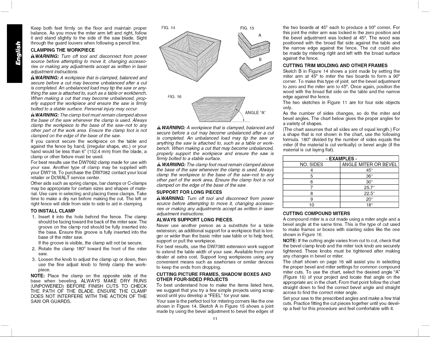
Your saw is the perfect tool for mitering corners like the one
shown in Figure 14. Sketch A in Figure 15 shows a joint
made by using the bevel adjustment to bevel the edges of
11
the two boards at 45° each to produce a 90° corner. For
this joint the miter arm was locked in the zero position and
the bevel adjustment was locked at 45°. The wood was
positioned with the broad flat side against the table and
the narrow edge against the fence. The cut could also
be made by mitering right and left with the broad surface
against the fence.
CUTTING TRIM MOLDING AND OTHER FRAMES
Sketch B in Figure 14 shows a joint made by setting the
miter arm at 45° to miter the two boards to form a 90 °
corner. To make this type of joint, set the bevel adjustment
to zero and the miter arm to 45°. Once again, position the
wood with the broad flat side on the table and the narrow
edge against the fence.
The two sketches in Figure 11 are for four side objects
only.
As the number of sides changes, so do the miter and
bevel angles. The chart below gives the proper angles for
a variety of shapes.
(The chart assumes that all sides are of equal length.) For
a shape that is not shown in the chart, use the following
formula. 180° divided by the number of sides equals the
miter (if the material is cut vertically) or bevel angle (if the
material is cut laying flat).
- EXAMPLES -
NO. SIDES ANGLE MITER OR BEVEL
4 45°
5 36°
6 30°
7 25.7 °
8 22.5 °
9 20°
10 18°
CUTTING COMPOUND MITERS
A compound miter is a cut made using a miter angle and a
bevel angle at the same time. This is the type of cut used
to make frames or boxes with slanting sides like the one
shown in Figure 16.
NOTE: Ifthe cutting angle varies from cut to cut, check that
the bevel clamp knob and the miter lock knob are securely
tightened. These knobs must be tightened after making
any changes in bevel or miter.
The chart shown on page 16 will assist you in selecting
the proper bevel and miter settings for common compound
miter cuts. To use the chart, select the desired angle "A"
(Figure 16) of your project and locate that angle on the
appropriate arc in the chart. From that point follow the chart
straight down to find the correct bevel angle and straight
across to find the correct miter angle.
Set your saw to the prescribed angles and make a few trial
cuts. Practice fitting the cut pieces together until you devel-
op a feel for this procedure and feel comfortable with it.
Page 13
Example:Tomakea4sidedboxwith26°exteriorangles
(AngleA,Figure15),usetheupperrightarc.Find26°
onthearcscale.Followthehorizontalintersectingline
toeithersidetogetmiteranglesettingonsaw(42°).
Likewise,followtheverticalintersectinglinetothetopor
bottomtogetthebevelanglesettingonthesaw(18°).
Alwaystrycutsonafewscrappiecesofwoodtoverify
settingsonsaw.
CUTTINGBASEMOLDING
ALWAYSMAKEA DRYRUNWITHOUTPOWER
BEFOREMAKINGANYCUTS.
Straight90°cuts:
Positionthewoodagainstthefenceandholdit in
placeasshowninFigure11.Turnonthesaw,allow
thebladeto reachfullspeedandlowerthearm
smoothlythroughthecut.
CUTTINGBASEMOLDINGUPTO6.5"(165ram)HIGH
VERTICALLYAGAINSTTHEFENCE
PositionmaterialasshowninFigure11.
Allcutsmadewiththebackofthemoldingagainstthe
fenceandbottomofthemoldingagainstthebase.
INSIDECORNER:
Leftside
1.Miterleft45°
2. Saveleftsideofcut
Rightside
1.MiterRight45°
2. Saverightsideofcut
OUTSIDECORNER:
Leftside
1.Miterrightat45°
2. Saveleftsideofcut
Rightside
1.Miterleftat45°
2. Saverightsideofcut
Materialupto 6.5"(159mm)canbecutasdescribed
above.
CUTTINGCROWNMOLDING
Yourmitersawisbettersuitedtothetaskofcutting
crownmoldingthananytoolmade.Inordertofitproperly,
crownmoldingmustbecompoundmiteredwithextreme
accuracy.
Thetwoflatsurfacesonagivenpieceofcrownmolding
areatanglesthat,whenaddedtogether,equalexactly
90°.Most,butnotall,crownmoldinghasatoprearangle
(thesectionthatfitsflatagainsttheceiling)of52°anda
bottomrearangle(thepartthatfitsflatagainstthewall)
of38°.
Yourmitersawhasspecialpre-setmiterlatchpointsat
31.62°leftandrightforcuttingcrownmoldingattheproper
angleandbevelstoppawlsat33.85°leftandright.There
isalsoamarkontheBevelscaleat33.85°.
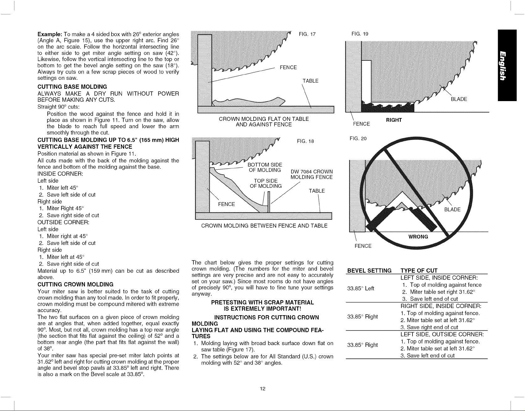
FIG. 17
FENCE
TABLE
CROWN MOLDING FLAT ON TABLE
AND AGAINST FENCE
FIG. 18
BOTTOM SIDE
OF MOLDING
CROWN MOLDING BETWEEN FENCE AND TABLE
The chart below gives the proper settings for cutting
crown molding. (The numbers for the miter and bevel
settings are very precise and are not easy to accurately
set on your saw.) Since most rooms do not have angles
of precisely 90°, you will have to fine tune your settings
anyway.
PRETESTING WITH SCRAP MATERIAL
IS EXTREMELY IMPORTANT!
INSTRUCTIONS FOR CUTTING CROWN
MOLDING
LAYING FLAT AND USING THE COMPOUND FEA-
TURES
1. Molding laying with broad back surface down flat on
saw table (Figure 17).
2. The settings below are for All Standard (U.S.) crown
molding with 52° and 38 ° angles.
DW 7O84 CROWN
MOLDING FENCE
TABLE
FIG. 19
FENCE
FIG. 20
FENCE
BEVEL SETTING
33.85 ° Left
33.85 ° Right
33.85 ° Right
BLADE
RIGHT
TYPE OF CUT
LEFT SIDE, INSIDE CORNER:
1. Top of molding against fence
2. Miter table set right 31.62 °
3. Save left end of cut
RIGHT SIDE, INSIDE CORNER:
1. Top of molding against fence.
2. Miter table set at left 31.62 °
3. Save right end of cut
LEFT SIDE, OUTSIDE CORNER:
1. Top of molding against fence.
2. Miter table set at left 31.62 °
3. Save left end of cut
12
Page 14
BEVEL SETTING FIG.21
TYPE OF CUT
RIGHT SIDE, OUTSIDE
CORNER:
33.85 ° Left
1. Top of molding against fence
2. Miter table set right 31.62 °
3. Save right end of cut
When setting bevel and miter angles for all compound
miters, remember that:
The angles presented for crown moldings are very
precise and difficult to set exactly. Since they can
easily shift slightly and very few rooms have exactly
square corners, all settings should be tested on scrap
molding.
PRETESTING WITH SCRAP MATERIAL IS
EXTREMELY IMPORTANT!
ALTERNATIVE METHOD FOR CUTTING
CROWN MOLDING
Place the molding on the table at an angle between the
FIG. 22
fence and the saw table, as shown in Figure 18. Use of
the crown molding fence accessory (DW7084) is highly
recommended because of its degree of accuracy and
convenience. The crown molding fence accessory is avail-
able for purchase from your local dealer.
The advantage to cutting crown molding using this method
isthat no bevel cut is required. Minute changes inthe miter
angle can be made without affecting the bevel angle. This
way, when corners other than 90° are encountered, the
saw can be quickly and easily adjusted for them. Use the
crown molding fence accessory to maintain the angle at
which the molding will be on the wall.
INSTRUCTIONS FOR CUTTING CROWN MOLDING
ANGLED BETWEEN THE FENCE AND BASE OF THE
SAW FOR ALL CUTS:
1. Angle the molding so the bottom of the molding (part
which goes against the wall when installed) is against
the fence and the top of the molding is resting on the
base of the saw, as shown in Figure 18.
2. The angled fflats" on the back of the molding must rest
FIG. 23
squarely on the fence and base of the saw.
INSIDE CORNER:
Left side
1. Miter right at 45°
2. Save the right side of cut
Right side
1. Miter left at 45°
2. Save left side of cut
OUTSIDE CORNER:
Left side
1. Miter left at 45°
2. Save right side of cut
RIGHT
WRONG
Right side
1. Miter right at 45°
2. Save left side of cut
Special Cuts
NEVER MAKE ANY CUT UNLESS THE MATERIAL
IS SECURED ON THE TABLE AND AGAINST THE
FENCE.
ALUMINUM CUTTING
ALWAYS USE THE APPROPRIATE SAW BLADE MADE
ESPECIALLY FOR CUTTING ALUMINUM. These are
available at your local DEWALT retailer or DEWALT ser-
vice center. Certain workpieces, due to their size, shape
or surface finish, may require the use of a clamp or fixture
to prevent movement during the cut. Position the material
so that you will be cutting the thinnest cross section, as
shown in Figure 19. Figure 20 illustrates the wrong way
to cut these extrusions. Use a stick wax cutting lubricant
when cutting aluminum. Apply the stick wax cutting lubri-
cant directly to the saw blade before cutting. Never apply
stick wax to a moving blade.
The wax, available at most hardware stores and industrial
mill supply houses, provides proper lubrication and keeps
chips from adhering to the blade.
Be sure to properly secure workpiece. Refer to page 5 for
correct saw blade.
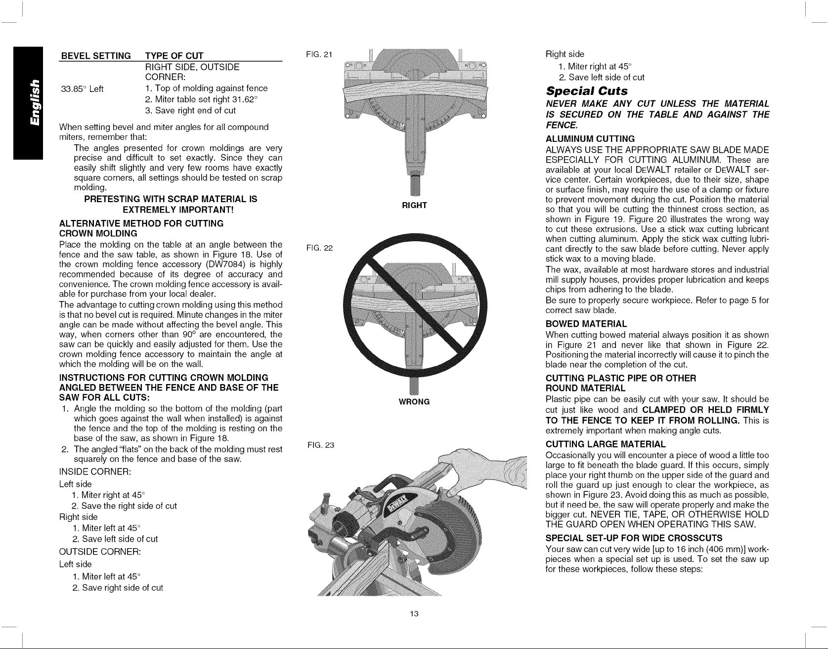
BOWED MATERIAL
When cutting bowed material always position it as shown
in Figure 21 and never like that shown in Figure 22.
Positioning the material incorrectly will cause it to pinch the
blade near the completion of the cut.
CUTTING PLASTIC PIPE OR OTHER
ROUND MATERIAL
Plastic pipe can be easily cut with your saw. It should be
cut just like wood and CLAMPED OR HELD FIRMLY
TO THE FENCE TO KEEP IT FROM ROLLING. This is
extremely important when making angle cuts.
CUTTING LARGE MATERIAL
Occasionally you will encounter a piece of wood a little too
large to fit beneath the blade guard. If this occurs, simply
place your right thumb on the upper side of the guard and
roll the guard up just enough to clear the workpiece, as
shown in Figure 23. Avoid doing this as much as possible,
but if need be, the saw will operate properly and make the
bigger cut. NEVER TIE, TAPE, OR OTHERWISE HOLD
THE GUARD OPEN WHEN OPERATING THIS SAW.
SPECIAL SET-UP FOR WIDE CROSSCUTS
Your saw can cut very wide [up to 16 inch (406 mm)] work-
pieces when a special set up is used. To set the saw up
for these workpieces, follow these steps:
13
Page 15
1.Removebothleftandrightslidingfencesfromthesaw
andsetaside.Toremovethem,unscrewthefence
knobsseveralturnsandslideeachfenceoutward.
Adjustandlockthemitercontrolsothatit is at0
degreesmiter.
2. Makea platformusinga pieceof 1.5inch(38mm)
thickparticleboardorsimilarflatstrong1.5inchthick
woodtothedimensions:14.5"x26"(368x660mm).
Theplatformmustbeflatotherwisethematerialcould
moveduringcuttingandcauseinjury.
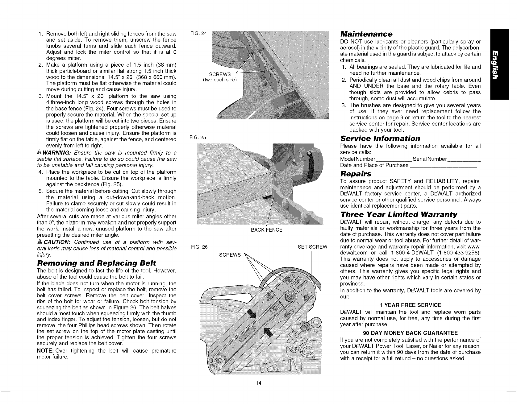
3. Mountthe 14.5"x 26"platformto thesawusing
4three-inchlongwoodscrewsthroughtheholesin
thebasefence(Fig.24).Fourscrewsmustbeusedto
properlysecurethematerial.Whenthespecialsetup
isused,theplatformwillbecutintotwopieces.Ensure
thescrewsaretightenedproperlyotherwisematerial
couldloosenandcauseinjury.Ensuretheplatformis
firmlyflatonthetable,againstthefence,andcentered
evenlyfromlefttoright.
WARNING: Ensure the saw is mounted firmly to a
stable flat surface. Failure to do so could cause the saw
to be unstable and fall causing personal injury.
4. Place the workpiece to be cut on top of the platform
mounted to the table. Ensure the workpiece is firmly
against the backfence (Fig. 25).
5. Secure the material before cutting. Cut slowly through
the material using a out-down-and-back motion.
Failure to clamp securely or cut slowly could result in
the material coming loose and causing injury.
After several cuts are made at various miter angles other
than 0 °,the platform may weaken and not properly support
the work. Install a new, unused platform to the saw after
presetting the desired miter angle.
A CAUTION: Continued use of a platform with sev-
eral kerfs may cause loss of material control and possible
injury.
Removing and Replacing Belt
The belt is designed to last the life of the tool. However,
abuse of the tool could cause the belt to fail.
If the blade does not turn when the motor is running, the
belt has failed. To inspect or replace the belt, remove the
belt cover screws. Remove the belt cover. Inspect the
ribs of the belt for wear or failure. Check belt tension by
squeezing the belt as shown in Figure 26. The belt halves
should almost touch when squeezing firmly with the thumb
and index finger. To adjust the tension, loosen, but do not
remove, the four Phillips head screws shown. Then rotate
the set screw on the top of the motor plate casting until
the proper tension is achieved. Tighten the four screws
securely and replace the belt cover.
NOTE: Over tightening the belt will cause premature
motor failure.
FIG. 24
(two each side)
FIG. 25
FIG. 26
SCREWS
SCREWS
BACK FENCE
SET SCREW
Maintenance
DO NOT use lubricants or cleaners (particularly spray or
aerosol) in the vicinity of the plastic guard. The polycarbon-
ate material used in the guard is subject to attack by certain
chemicals.
1. All bearings are sealed. They are lubricated for life and
need no further maintenance.
2. Periodically clean all dust and wood chips from around
AND UNDER the base and the rotary table. Even
though slots are provided to allow debris to pass
through, some dust will accumulate.
3. The brushes are designed to give you several years
of use. If they ever need replacement follow the
instructions on page 9 or return the tool to the nearest
service center for repair. Service center locations are
packed with your tool.
Service Information
Please have the following information available for all
service calls:
Model Number Serial Number
Date and Place of Purchase
Repairs
To assure product SAFETY and RELIABILITY, repairs,
maintenance and adjustment should be performed by a
DEWALT factory service center, a DEWALT authorized
service center or other qualified service personnel. Always
use identical replacement parts.
Three Year Limited Warranty
DEWALT will repair, without charge, any defects due to
faulty materials or workmanship for three years from the
date of purchase. This warranty does not cover part failure
due to normal wear ortool abuse. For further detail of war-
ranty coverage and warranty repair information, visit www.
dewalt.com or call 1-800-4-DEWALT (1-800-433-9258).
This warranty does not apply to accessories or damage
caused where repairs have been made or attempted by
others. This warranty gives you specific legal rights and
you may have other rights which vary in certain states or
provinces.
In addition to the warranty, DEWALT tools are covered by
our:
1 YEAR FREE SERVICE
DEWALT will maintain the tool and replace worn parts
caused by normal use, for free, any time during the first
year after purchase.
90 DAY MONEY BACK GUARANTEE
If you are not completely satisfied with the performance of
your DEWALT Power Tool, Laser, or Nailer for any reason,
you can return it within 90 days from the date of purchase
with a receipt for a full refund - no questions asked.
14
Page 16
RECONDITIONEDPRODUCT:Reconditionedproductis
coveredunderthe1YearFreeServiceWarranty.The90
DayMoneyBackGuaranteeandtheThreeYearLimited
Warrantydonotapplytoreconditionedproduct.
FREEWARNINGLABELREPLACEMENT:If your
warninglabelsbecomeillegibleor aremissing,call
1-800-4-DEWALTforafreereplacement.
Patent Notification
Manufactured under one or more of the following U.S.
patents:
6,823,765 6,101,914 5,907,987 5,375,495
6,810,780 6,035,754 5,862,734 5,285,708
6,520,059, 6,032,563 5,582,089 5,199,343
Other patents may be pending.
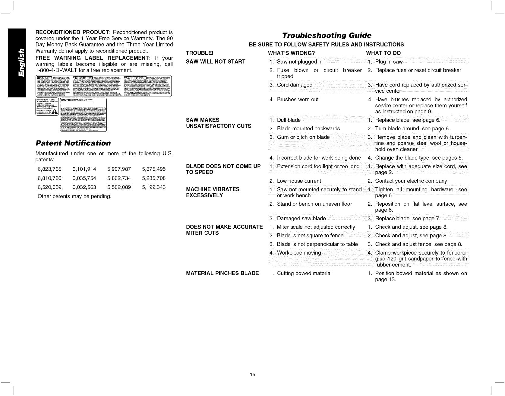
BE SURE TO FOLLOW SAFETY RULES AND INSTRUCTIONS
TROUBLE!
SAW WILL NOT START
SAW MAKES
UNSATISFACTORY CUTS
BLADE DOES NOT COME UP
TO SPEED
MACHINE VIBRATES
EXCESSIVELY
DOES NOT MAKE ACCURATE
MITER CUTS
MATERIAL PINCHES BLADE
Troubleshooting Guide
WHAT'S WRONG? WHAT TO DO
ii Saw notpiugged in li Plug insaw
2. Fuse blown or circuit breaker 2. Replace fuse or reset circuit breaker
tripped
31 Cord damaged 31 Have coid replaced bY authorized ser_
vice center
4. Brushes worn out 4. Have brushes replaced by authorized
service center or replace them yourself
as instructed on page 9.
Dull blade ii Repiace blade' see page 61
2. Blade mounted backwards 2. Turn blade around, see page 6.
3. Gum or pitch on blade 3: Remove blade and clean with turpen-
tine and coarse steel wool or house,
........................ hold oven cleaner
4. Incorrect blade for work being done 4. Change the blade type, see pages 5.
Extensi0n Cord too light or to0 long 11 Replace with adequate size cor d, see
page 2.
2. Low house current 2. Contact your electric company
llSaw not mounted securely to stand 11 Tighten all mounting hardware, see
or work bench page 6.
2. Stand or bench on uneven floor 2. Reposition on flat level surface, see
page 6.
3. Damaged saw blade & Replace blade' see page 7:
1. Miter scale not adjusted correctly 1. Check and adjust, see page 8.
2. Blade is not square to fence 21 Check and adjust, see page&
3. Blade is not perpendicular to table 3. Check and adjust fence, see page 8.
4. woikpiece moving 4. ClamP workpiece securely to fence or
glue 120 grit sandpaper to fence with
rubber cement.
1. Cutting bowed material 1. Position bowed material as shown on
page 13.
15
Page 17
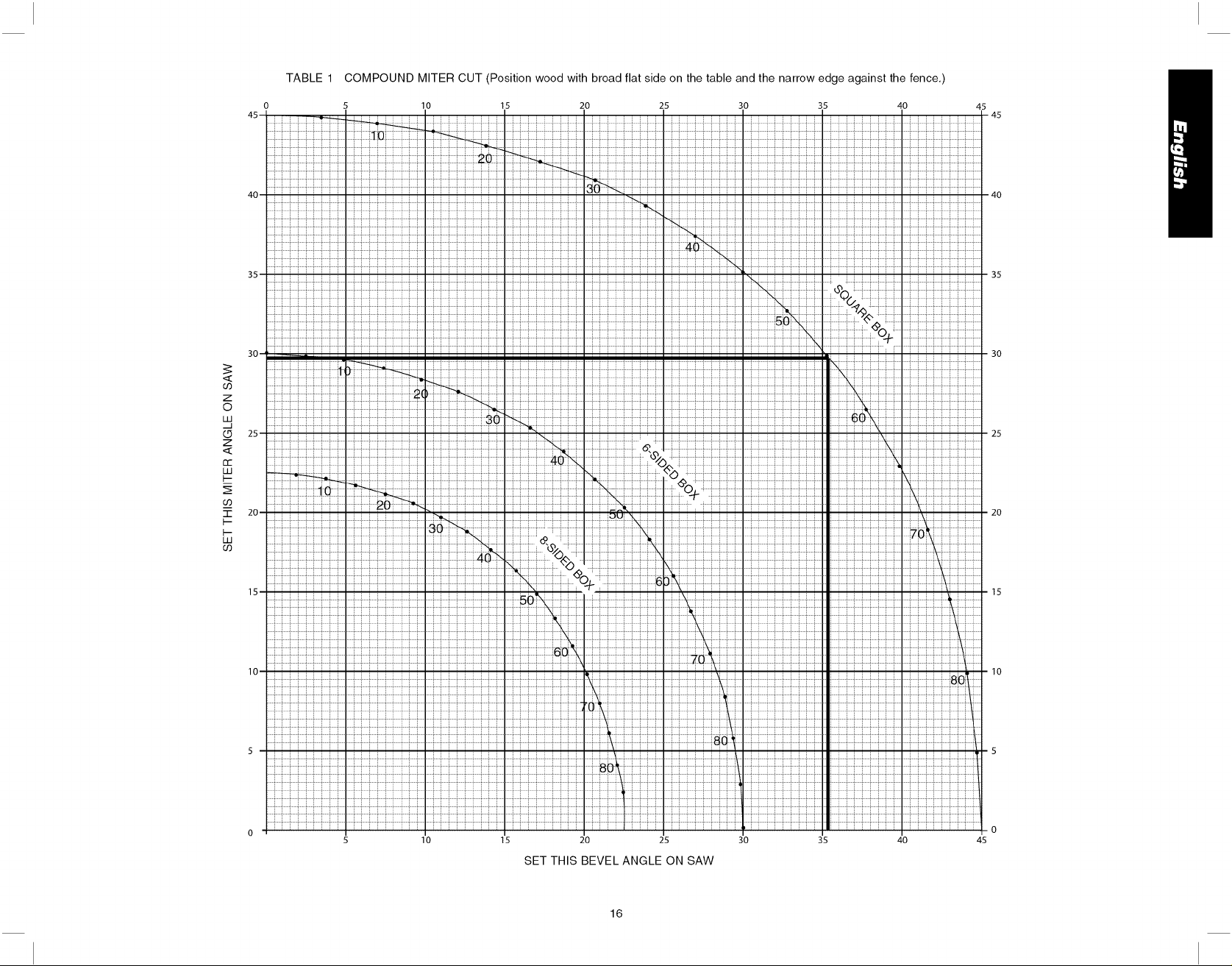
TABLE 1 COMPOUND MITER CUT (Position wood with broad flat side on the table and the narrow edge against the fence,)
45-
40-
35-
30-1
: _---1Tll i : :
<
Z
o
W
.d
25-
Z
<
re
UJ
10 30 35 4015 20 25
45
- 45
- 40
35
30
25
: ::ii iiiiiiiiiiiii[iiiiii
20-
"-r
20
UJ
_iiiiiiiiiiiiiiiiiiiiii_, iii
15-
10-
5 -
5o
8_
10
15 20 25
SET THIS BEVEL ANGLE ON SAW
16
iiiiiiiii iiiiiiii
30 35 40 45
15
10
Page 18

TABLE DES MA TI_'RES
INSTRUCTIONS RELATIVES ,_ LA DOUBLE ISOLATION ET
,_ LA FICHE POLARISC:E ............................................................................................ 18
REGLES DE S¢:CURIT¢: POUR TOUS LES OUTILS ................................................ 18
RI_GLES DE S¢:CURIT¢: SUPPLC:MENTAIRES ......................................................... 19
CONNEXION €:LECTRIQUE ........................................................................ 21
ACCESSOIRES ............................................................................................................ 21
DESCRIPTIONS DE LA LAME .................................................................................... 22
DC:SEMBALLAGE DE VOTRE SCIE ........................................................................... 22
FICHE TECHNIQUE ..................................................................................................... 22
FAMILIARISATION ....................................................................................................... 22
MONTAGE SUR €:TABLI ............................................................................................. 23
CHANGEMENT OU POSE D'UNE NOUVELLE LAME DE SCIE ............................ 23
De:POSE DE LA LAME ................................................................................................ 22
POSE D'UN LAME ....................................................................................................... 23
TRANSPORT DE LA SCIE .......................................................................................... 24
RC:GLAGES .................................................................................................................. 24
RC:GLAGE DE L'C:CHELLE D'ONGLET .................................................................. 24
RC:GLAGE DU POINTEUR D'ONGLET ................................................................... 24
BISEAU D'C:QUERRE AVEC LA TABLE ................................................................. 25
POINTEUR DE BISEAU ........................................................................................... 25
AJUSTEMENT DROIT ET GAUCHE DE 45 o DE LA BUTEE DE BISEAU ........... 25
RC:GLAGE DU GUIDE ............................................................................ 25
FREIN €:LECTRIQUE AUTOMATIQUE .................................................................... 25
ACTIVATION ET VISIBILIT¢: DU PARE-MAIN ........................................................ 26
RC:GLAGE DE LA PLAQUE DE TRAIT DE SCIE ................................................... 26
RC:GLAGE DE LA GLISSII_RE DE S¢:CURIT¢: ....................................................... 26
BROSSES ..................................................................................................................... 26
COMMANDES .............................................................................................................. 26
FONCTIONNEMENT .................................................................................................... 27
INTERRUPTEUR .................................................................................................... 27
DI2COUPE/_ L'AIDE DE VOTRE SClE ................................................................. 27
COUPES TRANSVERSALES .................................................................................. 27
COUPES EN BISEAU .............................................................................................. 28
QUALITI 2 DE COUPE ............................................................................................... 28
POSITION DU CORPS ET DES MAINS ................................................................. 28
FIXATION DE LA PIECE ........................................................................................ 28
INSTALLATION DE LA BRIDE ............................................................................... 28
SOUTIEN DES PIECES LONGUES ....................................................................... 28
DI2COUPE DE CADRES,. DE COFFRAGES
ET D'AUTRES OBJETS A QUATRE FACES ........................................................ 29
DI2COUPE DE MOULURES DE GARNISSAGE
ET D'AUTRES CADRES ......................................................................................... 29
DI2COUPE A ONGLET MIXTE ............................................................................... 29
DI2COUPE DE MOULURES D'EMBASE ............................................................... 30
DI2COUPE DE MOULURES COURONNEES ....................................................... 30
DI2COUPES SPI2ClALES ............................................................................................ 31
DI2POSE ET REMPLACEMENT DE LA COURROIE ................................................. 32
INFORMATION SUR LES RI2PARATIONS OU L'ENTRETIEN .............................. 32
ENTRETIEN .................................................................................................................. 32
GARANTIE .................................................................................................................... 32
GUIDE DE DI2PANNAGE ............................................................................................. 33
TABLEAU 1 : DI2COUPE A ONGLET MIXTE ............................................................. 34
RI2GLAGE DU BLOCAGE D'ONGLET .................................................................... 26
17
Page 19

D_finitions : lignes directrices en
mati_re de s_curit_
Les d6finitions ci-dessous d6crivent le niveau de danger pour chaque mot-indicateur
employ& Lire le mode d'emploi et porter une attention particuli_re & ces symboles.
,&DANGER : indique une sfuation dangereuse imminente qui, si elle n'est pas
evit6e, causera la mort ou des blessures graves.
_kA VERTISSEMENT : indique une situation potentiellement dangereuse qui, si elle
n'est pas evit6e, pourrait causer la mort ou des blessures graves.
J_MISE EN GARDE : indique une situation potentiellement dangereuse qui, si elle
n'est pas evit6e, peut causer des blessures mineures ou moderees.
MISE EN GARDE : utilise sans le symbole d'alerte de securite, indique une situation
potentiellement dangereuse qui, si elle n'est pas evit6e, peut causer des dommages
materiels.
POUR TOUTE QUESTION OU TOUT COMMENTAIRE SUR CET OUTIL OU SUR
TOUT AUTRE OUTIL DEWALT, COMPOSER LE NUMC:RO SANS FRAIS SUIVANT :
1-800-4-DEWALT (1-800-433-9258).
Consignes de s_curit_ importantes
_ A VERTISSEMENT : lire toutes les directives avant d'utiliser le produit. Negliger
de suivre toutes les directives suivantes peut entraTner des risques de chocs
electriques, d'incendie et/ou de blessures graves.
LIRE TOUTES CES DIRECTIVES
Double isolation
Les outils & double isolation comportent partout deux couches d'isolation 61ectrique
s6par6es ou une double 6paisseur de mat6riau isolant entre I'op6rateur et le syst_me
61ectrique de I'outil. Les outils comportant ce syst_me d'isolation ne sont pas con£us pour
6tre mis & la terre. L'outil est donc dot6 d'une prise & deux broches qui permet d'utiliser
des rallonges sans avoir & se soucier de maintenir une connexion & la terre.
REMARQUE : la double isolation ne remplace pas les pr6cautions normales de s6cu-
rit6 Iors de rutilisation de cet outil. Le syst_me d'isolation sert & apporter une protection
accrue contre toute blessure r6sultant d'une d6faillance d'isolation 61ectrique potentielle &
I'int6rieur de I'outil.
_MISE EN GARDE: EN CAS DE REPARATION, UTILISER UNIQUEMENT DES
PIECES DE RECHANGE IDENTIQUES. Reparer ou remplacer les cordons d'alimentation
endommages.
Fiches polaris_es
Certains appareils comportent des fiches polaris6es (c'est-&-dire qu'une lame est plus
large que I'autre) afin de r6duire le risque de choc 61ectrique. Lorsqu'elle est pr6sente,
cette fiche ne se branche que d'une seule fa£on dans une prise de courant polaris6e. Si
la fiche ne s'ins_re pas totalement dans la prise de courant, I'inverser. Si elle ne s'ins_re
toujours pas dans la prise, demander & un 61ectricien comp6tent d'installer une fiche
polaris6e. Ne pas remplacer la fiche.
Consignes de s_curit_ pour tous les outils
• MAINTENIR LE PROTEGE-LAME EN PLACE et en etat de fonctionnement.
• RETIRER LES CLES,4 MOLETTE ET LES CLES DE REGLAGE. S'habituer a verifier
si les cles a molette et les cles de reglage sont retirees de la broche avant de mettre
I'outil sous tension. Des outils, des dechets de decoupe et d'autres debris peuvent 6tre
projetes a grande vitesse, provoquant des blessures.
• GARDER LA ZONE DE TRA VAIL PROPRE. Les zones et etablis encombres sont
souvent des causes d'accidents.
• NE PAS UTILISER L'APPAREIL DANS UN ENVlRONNEMENT DANGEREUX.
L'utilisation d'outils electriques dans des endroits humides ou mouilles ou sous la pluie
peut provoquer un choc electrique ou une electrocution. Tenir la zone de travail bien
eclair6e pour eviter de trebucher ou de mettre bras, mains et doigts en danger.
• TENIR LES ENFANTS ,4 L'ECART. Tousles visiteurs doivent se trouver a une dis-
tance sDre de la zone de travail. Un atelier represente un environnement potentielle-
ment dangereux.
• S'ASSURER QUE L'ATELIER NE PRESENTE PAS DE DANGER POUR LES
ENFANTS : utiliser des cadenas, des interrupteurs principaux ou retirer les cles de
demarrage. Le demarrage non autorise d'un appareil par un enfant ou un visiteur pour-
rait se solder par des blessures.
• NE PAS FORCER L'OUTIL. Le travail sera mieux accompfi et sera moins dangereux
au rythme prevu pour I'appareiL
• UTILISER L'OUTIL APPROPRIE. Ne pas forcer un outil ou un accessoire pour
effectuer un travail auquel il n'a pas ete con_u. L'utilisation d'un outil ou d'un accessoire
inapproprie pourrait se solder par des blessures corporelles.
• PORTER LES VETEMENTS APPROPRIES. Ne pas porter ni v6tement ample, ni gant,
ni cravate, ni bague, ni bracelet, ni autre bijou, car ces demiers pourraient s'enchev6trer
dans des pieces mobiles. Des souliers antiderapants sont recommandes. Se couvrir
les cheveux s'ils sont longs. Se tenir eloigne des events, car ces demiers pourraient
camoufler des pieces mobiles.
• TOUJOURS PORTER DES LUNETTES DE SECURITE. Les lunettes ordinaires ne
constituent PAS des lunettes de securite. Utiliser egalement un masque facial ou anti-
poussiere si I'operation de decoupe genere de la poussiere. TOUJOURS PORTER UN
EQUIPEMENT DE SECURITE HOMOLOGUE :
• protection oculaire conforme a la norme ANSI Z87.1 (CAN/CSA Z94.3);
• protection auditive conforme a la norme ANSI $12.6 ($3.19);
• protection des voies respiratoires conforme aux normes NIOSH/OSHA/MSHA.
• FIXER LA PIECE. Utiliser des brides de fixation ou un etau pour maintenir la piece sur
la table et contre le guide. Faire de m6me Iorsque le travail a effectuer exigera que la
main de I'operateur se trouve tres proche de la lame (a moins de 152 mm [6 po]). Une
telle pratique est plus securitaire, car I'operateur peut utiliser ses deux mains pour faire
fonctionner I'outiL
• NE PAS TROP TENDRE LES BRAS. Conserver son equilibre en tout temps. Une
perte d'equilibre risque d'entrafner une blessure corporelle.
• PRENDRE SOIN DES OUTILS. S'assurer que les outils sont aiguises et propres afin
d'optimiser securite et performance. Suivre les consignes de graissage et de change-
ment d'accessoires. Les machines et outils mal entretenus peuvent s'endommager
davantage et/ou provoquer des blessures.
• ETEINDRE L'APPAREIL ET COUPER LE COURANT avant d'installer ou de retirer
des accessoires, avant de realiser ou de modifier un reglage et lots de reparations
ou de deplacements de I'appareil. Un demarrage accidentel peut provoquer des bles-
sures. Ne pas toucher aux lames metalliques de la fiche Iors du branchement ou du
debranchement du cordon d'alimentation.
• RL_DUIRE LE RISQUE DE DL_MARRAGE ACCIDENTEL. S'assurer que I'interrupteur
se trouve sur la position, ARRET _ avant de brancher le cordon d'alimentation.
• UTILISER UNE RALLONGE APPROPRIEE. S'assurer que la rallonge est en bon etat.
Si le produit est dote d'un cordon amovible, utiliser uniquement une rallonge a 3 ills
pourvue d'une fiche de mise a la terre a 3 lames et d'une prise a 3 fentes correspon-
dant a la fiche de I'outiL Lorsqu'une rallonge est utilisee, s'assurer d'utiliser un calibre
18
Page 20

suffisamment eleve pour assurer le transport du courant necessaire au fonctionnement
de I'appareil. Une rallonge de calibre inferieur causera une chute de tension de ligne et
donc une perte de puissance et une surchauffe. Le tableau suivant indique le calibre
approprie a utiliser selon la Iongueur de la rallonge et I'intensite nominale de la plaque
signaletique. En cas de doute, utiliser le calibre superieur suivant. Plus le numero de
calibre est petit, plus le cordon est de calibre elev6.
Calibre minimal pour rallonge
Tension Longueur totale du cordon en m_tres (pieds)
120V (0 &25) (26 & 50) (51 &lO0) (101 &150)
240 V
Intensit6 nominale
Plus de Pas plus
de
0- 6
6- 10
10 - 12
12 - 16
• VERIFIER QUE LES PIECES NE SONT PAS ENDOMMAGEES. Avant toute utilisa-
tion ulterieure de Ibutil, un protege-lame (ou une autre piece) endommage do# 6tre
soigneusement examine afin de determiner s'il fonctionnera correctement et remplira
sa fonction prevue- verifier I'alignement des pieces mobiles, la presence de grippage
des pieces mobiles, de rupture de pieces, la fixation et tout probleme pouvant nuire
au fonctionnement de Ibutil. Un protege-lame (ou toute autre piece) endommage doit
6tre repare et remplace adequatement. Ne pas utiliser I'appareil si I'interrupteur ne
fonctionne pas.
• UTILISER LES ACCESSOIRES RECOMMANDES. N'utiliser que les accessoires con-
seilles par le fabricant pour le modele de Ibutil. Des accessoires qui conviennent a un
outil pourraient 6tre dangereux Iorsqu'ils sont utilises avec un autre outil. Une liste des
accessoires recommandes se trouve dans le mode d'emploi. L'utilisation d'accessoires
incorrects peut entrafner un risque de blessure corporelle.
• NE JAMAIS SE TENIR SUR L'OUTIL. Une blessure grave pourrait se produire en cas
de basculement de Ibutil ou de demarrage accidentel de Ibutil de decoupe.
• NE JAMAIS LAISSER L'OUTIL FONCTIONNER SANS SURVEILLANCE. ETEINDRE
L'APPAREIL. Ne pas laisser I'outil tant qu'il n'est pas completement arr6te. De graves
blessures pourraient survenir.
• NE PAS UTILISER D'OUTILS ELECTRIQUES A PROXlMITE DE LIQUIDES
INFLAMMABLES OU DANS UNE ATMOSPHERE GAZEUSE OU EXPLOSIVE. Les
moteurs de ces outils peuvent provoquer des etincelles et enflammer des vapeurs.
• ETRE VIGILANT, SURVEILLER LE TRAVAIL EFFECTUE ET FAIRE PREUVE DE
JUGEMENT. NE PAS UTILISER L'APPAREIL EN CAS DE FATIGUE OU SOUS
L'INFLUENCE DE DROGUES, D'ALCOOL ou DE MEDICAMENTS. En effet, un
moment d'inattention en utilisant des outils electriques peut se solder par des
blessures.
0 & 7,5 7,6 & 15,5 15,6 &30,5 30,6 & 45,5
0 & 15,5 15,6 & 30,5 30,6 & 61 61,2 & 91,5
(0 & 50) (51 & 100) (101 & 200) (201 & 300)
AWG
18 16 16 14
18 16 14 12
16 16 14 12
14 12 Non recommand6
Rdgles de sdcuritd suppldmentaires pour les
scies a onglets
AAVERTISSEMENT : ne pas laisser une bonne connaissance de Ibutil (acquise par
I'utilisation frequente de la scie) prendre preseance sur les regles de securite. Toujours se
souvenir qu'une fraction de seconde d'imprudence est suffisante pour infliger de graves
blessures.
• NE PAS FAIRE FONCTIONNER CET APPAREIL avant qu'il ne soit entierement
assemble et installe conformement aux directives. Un appareil mal assemble peut pro-
voquer des blessures graves.
• DEMANDER CONSEIL a un superviseur, a un instructeur ou a toute autre personne
qualifiee si I'on ne mMtrise pas parfaitement I'utilisation de cet appareil. La connais-
sance est synonyme de securite.
• STABILITE. S'assurer que la scie a onglets est posee sur une surface portante fixe
et ne risque pas de glisser ou de se deplacer durant son utilisation. Si le systeme de
mobilite est installe, relever la ou les roulettes mobiles de maniere a ce que la scie soit
en position stable.
• SUIVRE TOUSLES CODES DE CABLAGE et les branchements electriques recom-
mandes afin d'eviter les chocs electriques ou I'electrocution. II faut proteger la ligne
d'alimentation electrique avec un fusible a temporisation ou un disjoncteur d'au moins
15 amperes.
• S'ASSURER que la lame toume dans le bon sens. Les dents de la lame doiventpointer
dans le sens de rotation, comme il est indique sur la scie.
• SERRER TOUTES LES POIGNEES DE FIXATION, les boutons et les leviers avant
I'utilisation de la scie. Si les brides sont I&ches, des pieces ou la piece a travailler pour-
raient 6tre projetees a grande vitesse.
• S'ASSURER que toutes les rondelles de lame et de bride de fixation sont propres,
que les c6tes encastres des bagues se trouvent contre la lame et que la vis d'arbre
est bien serree. Un mecanisme de serrage de lame I_che ou inadequat risquerait
d'endommager la scie et de provoquer des blessures corporelles.
• UTILISER TOUJOURS UNE LAME TRANCHANTE. Verifier que la lame fonctionne
bien dans I'axe et qu'elle ne vibre pas. Une lame emoussee ou une lame qui vibre peut
endommager I'appareil et/ou provoquer des blessures graves.
• NE PAS UTILISER UNE TENSION AUTRE QUE CELLE DESIGNEE pour la scie.
Une tension autre risquerait d'entrafner une surchauffe, des dommages a la scie et des
blessures corporelles.
• NE PAS PLACER QUOI QUE CE SOIT CONTRE LE VENTILATEUR pour retenir
I'arbre moteur. Une telle pratique peut endommager I'outil et entrafner des blessures
corporelles.
• NE PAS forcer I'action de coupe. Le calage partiel ou complet du moteur peut causer
des dommages a I'appareil ou a la lame et/ou des blessures graves.
• LAISSER LE MOTEUR ATTEINDRE SON PLEIN REGIME avant de commencer la
coupe. Commencer a couper trop t6t peut endommager I'appareil ou la lame et/ou
provoquer des blessures graves.
• NE JAMAIS COUPER DE METAUX FERREUX (metaux contenant du fer ou de I'acier)
ni de la ma_onnerie. En coupant I'un ou I'autre de ces materiaux, les pointes car-
burees peuvent se detacher de la lame, et ce, a grande vitesse. Cela peut provoquer
des blessures graves.
• NE PAS UTILISER DE MEULES ABRASIVES. La chaleur excessive et les particules
abrasives qu'elles produisent risquent d'endommager la scie et de causer des bles-
sures corporelles.
• AUCUNE partie du corps ne doit se trouver dans la trajectoire de la lame de la scie. Un
tel positionnement risque d'entrafner des blessures corporelles.
• NE JAMAIS appliquer de lubrifiant sur une lame en fonctionnement. L'application de
lubrifiant pourrait amener I'operateur a deplacer ses mains jusque sur la lame et ainsi
se blesser gravement.
• IL NE FAUT PAS placer une main a proximite de la lame Iorsque la scie est branchee
au bloc d'alimentation. Le fonctionnement inopine de la lame risquerait d'entrafner des
blessures graves.
19
Page 21

• NE PAS REALISER D'OPERA TIONS,4 MAIN LEVEE (piece a travailler non soutenue
par la table et le guide). Tenir la piece a travailler fermement contre le guide et la table.
Une operation a main levee avec une scie a onglets risquerait de projeter la piece
grande vitesse, provoquant ainsi des blessures graves.
• NE PAS PASSER LES MAINS AUTOUIt de la lame de scie ou derriere celle-ci. Une
lame peut provoquer des blessures graves.
• IL NE FAUT PAS passer les mains sous la scie sauf si elle est hors tension et
debranchee. Tout contact avec la lame de scie pourrait entraTner des blessures
corporelles.
• FIXER L'APPAItEIL SUIt UNE SURFACE DE SUPPORT STABLE. Les vibrations
sont susceptibles de faire glisser, sautiller ou basculer I'appareil, ce qui peut provoquer
des blessures graves.
• UTILISEIt UNIQUEMENT LES LAMES ,4 TRON_ONNEIt recommandees pour les
scies a onglets. Pour obtenir de meilleurs resultats, utiliser uniquement des angles de
coupe de zero degre ou negatifs lots de I'utilisation de lames a pointes carburees. Ne
pas utiliser des lames a dents tres espacees. Celles-ci peuvent devier et faire contact
avec le protege-lame et endommager ainsi I'appareil et/ou provoquer des blessures
graves.
• UTILISEIt SEULEMENT DES LAMES DE DIMENSION ET DE TYPE APPItOPItlES
prevues pour cet outil, et ce, pour eviter d'endommager I'appareil et/ou d'entrafner des
blessures graves.
• INSPECTEIt LA LAME POUR ItEPEitlEit DES FISSURES ou d'autres dommages
avant I'utilisation. Une lame fissuree ou endommagee peut se detacher et des
fragments peuvent 6tre projetes a grande vitesse, ce qui peut provoquer des blessures
graves. Remplacer les lames fissurees ou endommagees immediatement.
• NETTOYEIt LA LAME ET LES BRIDES DE LA LAME avant I'utilisation. Le nettoyage
de la lame et des brides permet de vbrifier que la lame ou les brides ne sont pas
endommagees. Une lame ou une bride fissuree ou endommagee peut se detacher
et des fragments peuvent 6tre projetes a grande vitesse, ce qui peut provoquer des
blessures graves.
• IL NE FAUT PAS utiliser de graisse ni de produits nettoyants (en particulier de
pulverisateur ou d'aerosol) a proximite du protege-lame en plastique. Certains produits
chimiques peuvent attaquer le materiau de polycarbonate dont il est constitue.
• TOUJOUItS UTILISEIt LA PLAQUE DE TRAIT DE SClE ET LA ItEMPLACEIt
LOItSQU'ELLE EST ENDOMMAGEE. L'accumulation de petits copeaux sous la scie
pourrait nuire a la lame ou rendre la piece instable /ors de la decoupe.
• UTILISEIt UNIQUEMENT DES BRIDES DE LAME prevues pour cet outil afin d'eviter
d'endommager I'appareil et/ou de provoquer des blessures graves.
• DEGAGEIt LES EVENTS DU MOTEUIt de toute sciure ou de tout copeau. Des
events de moteur obstrues peuvent provoquer la surchauffe de I'appareil, ce qui
I'endommagerait et provoquerait peut-Gtre un court-circuit qui pourrait engendrer des
blessures graves.
• TENIIt LES BItAS, LES MAINS ET LES DOIGTS eloignGs de la lame afin d'eviter des
coupures graves. Fixer solidement toutes les pieces qui exigeraient que la main soit
moins de 152mm (6 po) de la lame de scie.
• NE JAMAIS VERROUILLER L'INTERRUPTEUR en position de , MARCHE _. Une
telle pratique peut entrafner des blessures corporelles graves.
• ETEINDItE L'APPAREIL et laisser la lame s'immobiliser completement avant de
relever le bras, de nettoyer la zone de la lame, d'enlever les debris de la trajectoire de
la lame et avant I'entretien ou le reglage de I'outil. Une lame mobile peut provoquer des
blessures graves.
• SOUTENIIt COItRECTEMENT LES PIECES LONGUES OU LAItGES. La perte de
contrGle de la piece peut provoquer des blessures.
• NE JAMAIS croiser les bras devant la lame au moment d'utiliser Ibutil. Toujours
effectuer un fonctionnement a sec (non alimente) avant de realiser une coupe de
finition. Ainsi, la trajectoire de la lame peut 6tre verifiGe, ce qui permet d'eviter toute
blessure corporelle grave.
• DES INFOItMATIONS SUPPLEMENTAIItES (c.-a-d., une video sur la securite),
indiquant comment utiliser des outils electriques correctement et en toute securite,
sont disponibles aupres du Power Tool Institute, 1300 Sumner Avenue, Cleveland, OH
44115-2851 E.-U. (www.powertoolinstitute.com). Des renseignements sont egalement
offerts par le National Safety Council, 1121 Spring Lake Drive, Itasca, IL 60143-3201
E.-U. Se reporter a la norme ANSI 01.1 de /'American National Standards Institute
concemant les exigences en matiere de securite pour les appareils de travail du bois
ainsi qu'a la reglementation OSHA 1910.213 du departement du travail des E.-U.
(Department of Labor).
/&MISE EN GAItDE : Ne connectez pas I'appareil a une source d'alimentation electrique
tant que vous n'avez pas completement lu et compris les instructions..
_A VEItTISSEMENT : toujours porter une protection auditive appropri#e conform#-
ment a la norme ANSI S12.6 (S3.19) Iors de I'utilisation du produit. Dans certaines
conditions et selon la duree d'utilisation, le bruit emis par ce produit pourrait contribuer
une perte auditive.
i&A VEItTISSEMENT : NE JAMAIS EFFECTUER DE COUPE SI LE MA TERIAU N'EST
PAS MAINTENU EN PLACE SUR LA TABLE ET CONTRE LE GUIDE.
,_ A VEItTISSEMENT : Certaines poussieres produites par les activites de pon_age, de
sciage, de meulage, de pergage et autres activites de construction peuvent contenir des
produits chimiques pouvant causer le cancer, des anomalies congenitales ou d'autres
problemes lies aux fonctions reproductrices. Voici quelques exemples de ces produits
chimiques :
• le plomb contenu dans les peintures a base de plomb;
• la silice cristalline de la brique, du ciment et d'autres produits de ma_onnerie; et
• I'arseniate de cuivre et de chrome provenant du bois traite chimiquement.
Les risques relies a I'exposition aces poussieres varient selon la frequence a laquelle
vous travaillez avec ce type de materiaux. Afin de reduire votre exposition aces produits
chimiques : travaillez dans un endroit bien ventile et portez un equipement de securite
approuve comme un masque anti-poussieres congu specialement pour filtrer les particules
microscopiques.
• Evitez le contact prolong# avec les poussieres produites par les activit#s de
pon_age, sciage, meulage, per_age et autres activit#s de construction. Portez
des vGtements de protection et lavez les parties du corps expos#es avec une
solution d'eau et de savon. Le fait de laisser la poussiere p#n#trer par la bouche
et les yeux ou de la laisser reposer sur la peau, peut promouvoir I'absorption de
produits chimiques nocifs.
AA VEItTISSEMENT : L'utilisation de cet outil peut produire ou propulser des poussieres
qui pourraient causer des problemes respiratoires graves et permanents ou d'autres
problemes medicaux. Portez toujours un appareil respiratoire approuve par la NIOSH/
OSHA pour vous proteger de la poussiere. Dirigez les particules a I'ecart de votre visage
et de votre corps.
Pour plus de commodite et de securite, les etiquettes de securite suivantes sont apposees
sur votre scie a onglet.
SUR LE BO[TIER DU MOTEUR :
_&AVERTISSEMENT : POUR VOTRE
PItOPItE SECUItlTE, LISEZ LE MODE
D'EMPLOI AVANT D'UTILISEIt LA
SClE.
2O
ALWAYS ADJUST FENCEPROPERLYBEFOREUSE,
AJUSTE LA GUIA DEBiDAMENTE ANTES DE UT)LiZAR LA
HEBBAMJENTA. ASEGUBE LAS PJEZASPEQUENAS ANTES DE
CORTARLAS. CDNSULTE EL MANUAL.
CLAMP SMALL PIECESBEFORE CUTTING. SEE MANUAL.
TGUJODRS REGLERLE GUIDE AVANT £UTJLBSATiON, FIXER LES
PETITS ODJETS AVANT DE LES SCiER,CONSULTER LEGUIDE
D'UTILiSAT|ON.
Page 22

EN CAS DE RL_PARATION, UTILISEZ UNIQUEMENT DES PI#-CES DE
RECHANGE IDENTIQUES.
N'EXPOSEZ PAS LA SCIE A LA PLUIE ET NE L'UTILISEZ PAS DANS UN
ENDROIT HUMIDE.
PORTEZ TOUJOURS UNE PROTECTION OCULAIRE.
SUR LES GUIDES MOBILES :
AJUSTEZ TOUJOURS CORRECTEMENT LE GUIDE A VANT
UTILISATION. FIXEZ LES PETITES PI#-CES AVANT DE LES
DL_COUPER. VOIR LE MANUEL .................
SUR LE PARE-MAIN : DANGER - RESTEZ A L'L_CART DE _...............
K_PAWAY
FROMBL_O_
OEtA HOJA
LA LAME.
SUR LE PARE-MAIN SUPL_RIEUR : FIXEZ BIEN LE SUPPORT
DE FIXATION A VEC LES DEUX VISA VANT D'UTILISER LE
PRODUIT.
SUR LA TABLE : (A 2 ENDROITS)
SERREZ TOUJOURS BIEN LES POIGNL_ES DE RL_GLAGE AVANT
UTILISA TION.
GARDEZ LES MAINS A 15 CM (6 PO) DE LA TRAJECTOIRE
DE LA LAME DE LA SCIE.
N'EFFECTUEZ JAMAIS AUCUNE OPL_RATION A MAIN
LEVL_E.
NE PASSEZ JAMAIS LES BRAS DEVANT LA LAME.
RL_FLL_CHISSEZ! VOUS POUVEZ L_VITERLES ACCIDENTS
N'UTILISEZ PAS LA SCIE SANS QUE LES PARE-MAINS NE SOIT EN
PLACE.
L_TEIGNEZ L 'OUTIL, GARDEZ LA SCIE TETE EN BAS ET A TTENDEZ QUE
LA SCIE S'ARRETE AVANT DE DL_PLACER VOS MAINS OU LA PI__CE OU
DE MODIFIER LES RL_GLAGES.
DL_BRANCHEZ L'OUTIL A VANT DE CHANGER DE LAME, DE DL_PLACER
OU DE RL_PARER L'APPAREIL.
Connexion _lectrique
Assurez-vous que votre alimentation est compatible avec I'inscription de
la plaque signal_tique. 120 volts, C.A. signifie que votre scie fonctionne en
courant alternatif. L'interrupteur est susceptible de panne en cas d'utilisation
de courant continu. Une diminution de tension de 10 pour cent ou plus cause
une perte de puissance et une surchauffe. Tous les outils DEWALT sont test_s
en usine. Si cet outil ne fonctionne pas, v_rifiez I'alimentation.
Accessoires
Si vous avez besoin d'assistance pour trouver tout accessoire, veuillez
contacter DEWALT Industrial Tool Co., 701 East Joppa Road, Baltimore, MD
21286, Ctats-Unis, composer le 1 (800) 4-DEWALT (1-800-433-9258) ou
visiter notre site Web & www.dewalt.com.
i_AVERTISSEMENT : puisque les accessoires autres que ceux offerts par
DEWALT n'ont pas et6 testes avec ce produit, I'utilisation de ceux-ci avec
I'outil pourrait s'averer dangereuse. Pour reduire le risque de blessures,
utiliser exclusivement les accessoires DEWAL T recommandes avec le present
produit.
DW7080
PLAQUE
D'EXTREMITC
DW7051
ECROUS DE
VERROUILLAGE
SUPPORT
DW7082
DW7084
DW7187
21
Page 23

Accessoires facultatifs
Les accessoires suivants, con_us pour votre scie, peuvent vous 6tre utiles. Dans certains
cas, d'autres supports d'ouvrage, but6es r6glables, fixations, etc. peuvent 6tre plus
appropri6s. Faites attention Iors du choix et de I'utilisation d'accessoires
Syst_mes de guid6e par laser : DW7187
Un laser est vendu s6par6ment par les Centres de service DEWALT et votre magasin
de bricolage local. Les instructions d'installation sont fournies avec I'accessoire.
Lisez et respectez toutes les consignes pour installer et utiliser I'accessoire en toute
s6curit&
Extension, support d'ouvrage : DW7080
Le support d'ouvrage est utilis6 pour soutenir de Iongues pi_ces qui d6passent. II est
assembl6 par I'utilisateur. Votre table & scier est con£ue pour accepter deux supports
d'ouvrage, un de chaque c6t&
But6e r6glable : DW7051
N6cessite I'utilisation d'un support d'ouvrage (voir sch6ma). Elle sert & effectuer des
d6coupes r6p6titives de m6me Iongueur [comprise entre 0 et 106 cm (42 po)].
Bride de fixation : DW7082 (modUle semblable inclus)
Sert & fixer fermement la piece sur la table & scier pour une d6coupe de pr6cision.
Sac h poussi_re : DW7053 (livr6 avec certains modules)
12quip6d'une fermeture &glissi_re pour un vidage facile, le sac & poussi_re capture la
plus grande partie de la sciure produite (non illustr6).
Guide de moulures couronn6es : DW7084
Sert pour la d6coupe de pr6cision de moulures couronn6es.
Laser Guide System: DW7187
Powered by the saw, the bright laser line delivers enhanced visibility in low and high
light locations. Easy to install.
LAMES DE SOlE : TOUJOURS UTILISER DES LAMES DE SCIE DE 305 mm (12 po)
COMPORTANT DES ALI2SAGES CENTRAUX DE 25,4 mm (1 po). LE RI2GIME DOlT
12TREAU MOINS DE 4 800 TR/MIN. Ne jamais utiliser de lames de diam_tre inf6rieur.
Le protege-lame ne serait pas ad6quat. Utiliser uniquement des lames &trongonner! Ne
pas utiliser de lames congues pour un sciage rapide, des lames combin6es ou des lames
&crochets d'un angle sup6rieur & 5°.
DESCRIPTION DES LAMES
APPLICATION N° DE DIAM#TRE DENTS DENT
MODELE AFFUTAGE
Lames de scie de construction (fin trait de scie avec c&te antico//ant)
Polyvalente DW3123 12 po 32 ATB (pointe
Tron(_onnage fin DW3126 12 po
Tron(_onnage fin DW3128 12 po
Lames de scie pour travail du bois
'foumissent des coupes propres et regulibres)
Trongonnage fin DW7648 12 po
Trongonnage ultra-fin DW7649 12 po
Bois lamell6 DW7650 12 po
Surface solide et DW7661 12 po
plastiques
M6taux non ferreux DW7668 12 po
Non-ferrous metals DW7666 12 po
60 ATB
80 ATB
6O ATB
8O ATB
96 ATB
80 TCG (pointes&
80 Mod TCG
80 TCG
biseauteeen
alternance
double biseau)
(pointes& double
biseau modifie)
D_semballage de votre scie
V6rifiez lecontenu du carton de votre scie & onglet pour v6rifier que toutes les pi_ces vous
ont 6t6 livr6es. En plus de ce mode d'emploi, le carton devrait contenir :
1. Une scie & onglet DW718.
2. Une lame de scie DEWALT de 30 cm (12 po) de diam_tre.
3. Une cl6 de lame situ6e dans la poche de cl6 illustr6e & la figure 4.
4. Un sac & poussi_re DW7053 (certains modules).
5. Une bride de fixation de mat6riel.
Fiche technique
CAPACITI_ DE D#COUPE
Onglet droit & 50 o, onglet gauche & 60 o
Biseau droit et gauche & 48 o
Onglet &0 o
Hauteur maximale 94 mm (3,7 po)
Largeur maximale 345 mm (13,6 po)
Onglet &45 o
Hauteur maximale 94 mm (3,7 po)
Largeur maximale 241 mm (9,5 po)
Biseau & 45 o_ gauche
Hauteur maximale 61 mm (2,4 po)
Largeur maximale 345 mm (13,6 po)
Biseau & 45 o_ droite
Hauteur maximale 43 mm (1,7 po)
Largeur maximale 345 mm (13,6 po)
Votre scie est capable de d6couper des moulures de plinthes de 20 mm (0,8 po) de largeur
par 165 mm (6,5 po) de hauteur sur un onglet droit ou gauche & 45 o
Note: Your saw is capable of cutting the following once a special setup procedure is
followed (see Special Cuts).
onglet &0 o
onglet &45 o
ENTRA|NEMENT
Moteur 120 Volt
Puissance d'entr6e : 1 600
3 600 tr/min
Courroie trap6zofdale multiple
Frein 61ectrique automatique
hauteur 38 mm (1,5 po) largeur 40,9 mm (16,1 po)
hauteur 38 mm (1,5 po) largeur 40,9 mm (11,7 po)
Moteur 15 amperes
Engrenages h61icofdaux taill6s
Roulements &rouleau
Lame en carbure
Largeur r6sultante 328 mm (12,9 po)
Hauteur r6sultante 74 mm (2,9 po)
Largeur r6sultante 231 mm (9,1 po)
Hauteur r6sultante 74 mm (2,9 po)
Largeur r6sultante 328 mm (12,9 po)
Hauteur r6sultante 48 mm (1,9 po)
Largeur r6sultante 328 mm (12,9 po)
Hauteur r6sultante 28 mm (1,1 po)
Familiarisation
Votre scie & onglet est livr6e enti_rement assembl6e dans
le carton. Ouvrez la bofte et sortez la scie en la prenant par
la poign6e de transport commode, tel qu'illustr6 & la
figure 1.
Placez la scie sur une surface lisse et plane telle qu'un
6tabli ou une table solide.
22
FIG, 1
Page 24

Examinez les deux figures situ6es &la page 24 pour vous familiariser avec la scie et ses
diff6rentes pi_ces. La section concernant les r6glages se r6f_rera & ces termes et vous
devez savoir quelles sont les diff6rentes pi_ces et oQ elles se trouvent.
Appuyez 16g_rement sur la poign6e de fonctionnement et retirez FIG. 2
1'6pingle de verrouillage. Rel&chez doucement la pression vers le
bas et tenez le bras en lui permettant de se relever compl_tement.
Utilisez 1'6pingle de verrouillage Iorsque vous transportez la scie
d'un endroit & I'autre.
Pour d6placer la scie, utilisez toujours la poign6e de transport ou
les indentations manuelles illustr6es & la figure 2.
Montage sur _tabli
Les 4 pieds sont munis de trous pour faciliter le montage sur
6tabli, tel qu'illustr6 & la figure 4 (deux trous de taille diff6rente sont
pr6vus afin d'accueillir des vis de diff6rentes tallies. Utilisez I'un
des trous, il n'est pas n6cessaire d'utiliser les deux.) Assemblez
toujours fermement votre scie sur une surface stable pour 6viter
tout mouvement. Pour am61iorer la portabilit6 de I'outil, il peut 6tre mont6 sur une piece de
contreplaqu6 de 1,2 cm (1/2 po) ou plus d'6paisseur, qui peut & son tour 6tre fix6e &votre
support d'ouvrage ou d6plac6e vers un autre site de travail et fix6e & nouveau.
REMARQUE : Si vous avez d6cid6 de monter votre scie sur une piece de contreplaqu6,
assurez-vous que les vis de montage ne d6passent pas de la partie inf6rieure du bois. Le
contreplaqu6 dolt reposer & plat sur le support d'ouvrage. Lors de la fixation de la scie &
toute surface de travail, ne lafixez que sur les brides de fixation oQse situent les trous des
vis de montage. L'utilisation des brides de fixation &tout autre endroit interf_rerait &coup
st]r avec le fonctionnement ad6quat de la scie.
AMISE EN GARDE : Pour eviter tout grippage et manque de precision, assurez-vous
que la surface de montage n'est pas tordue et ne pr6sente pas d'autre d6faut. Si la scie
bascule sur la surface, placez une piece de materiau de faible epaisseur sous I'un des
pieds de la scie, jusqu'a ce que cette demiere soit fermement assise sur la surface de
montage.
DIRECTIVES DE SI_CURITI_ IMPORTANTES
Changement ou pose d'une nouvelle lame de scie
(fig. 3)
AA VERTI$$EMENT : eteindre I'outil et
le debrancher avant de le deplacer, de FIG. 3
changer les accessoires ou de realiser
des reglages autorises indiques dans
les directives de reglage du laser.
_MISE EN GARDE :
• N'enfoncez jamais le bouton de
verrouillage de la broche Iorsque
la lame est sous tension ou qu'elle
continue de toumer apres I'arr6t de
la scie.
• Ne coupez pas de metal ferreux
(contenant du fer ou de I'acier),
un el6ment de ma_onnerie ou du
fibrociment avec cette scie a onglet.
A
D_pose de la lame
1. D6branchez la scie.
2. Soulevez le bras jusqu'& la position
sup6rieure, puis levez le pare-main
(A) aussi haut que possible.
3. Desserrez la vis du support du
pare-main (B) sans I'enlever de
mani_re & ce que le support puisse
6tre lev6 suffisamment haut pour
acc6der & la vis de la lame. Le
pare-main inf6rieur demeurera lev6
en raison de la position de la vis du
support de pare-main.
4. Enfoncez le bouton de verrouillage
de la broche (C) tout en tournant
la lame de scie manuellement de
mani_re & engager le dispositif de
verrouillage.
5. Maintenez le bouton enfonc6 et utilisez I'autre
main et la cl6 fournie (D) pour desserrer la vis
de la lame. (Tournez dans le sens horaire,
filets invers6s).
6. Enlevez la vis (E) de la lame, la rondelle de
bride de fixation ext6rieure (F), la lame (G)
et I'adaptateur de lame (H), le cas 6ch6ant. II
est possible de laisser la rondelle de bride de
fixation int6rieure (I) sur la broche.
REMARQUE : L'adaptateur de lame de 25,4 mm
(1 po) (H) n'est pas utilis6 pour les lames dot6es
d'un trou de lame de 15,88 mm (5/8 po).
FIG. 3A
FIG. 3B
E F
Pose d'une lame
1. D6branchez la scie.
2. Le bras 6tant lev6, le pare-main inf6rieur
ouvert et le porte-pivot lev6, posez la lame sur
la broche, sur I'adaptateur de lame (si une lame & trou de 25,4 mm (1 po) est utilis6e)
et contre la rondelle de bride de fixation int6rieure, les dents se trouvant au bas de la
lame et pointant vers I'arri_re de la scie.
3. Assemblez la rondelle de bride de fixation ext6rieure sur la broche.
4. Posez la vis de la lame et, tout en engageant le bouton de verrouillage de la broche,
serrez fermement la vis avec la cl6 fournie. (Tournez dans le sens antihoraire, filets
invers6s)
REMARQUE : I'adaptateur de lame n'est pas utilis6 pour les lames & trou de 15,88 mm
(5/8 po) et dolt 6tre rang6 dans un endroit st]r pour un usage ult6rieur.
5. Remettez le support de pare-main & sa position d'origine, puis serrez fermement la vis
du support de pare-main afin de maintenir en place le support.
AA VERTISSEMENT :
• Le support du pare-main dolt _tre remis _ sa position
d'origine et la vis dolt _tre serree avant d'activer la scie.
• Si vous negligez du faire, le pare-main risque d'entrer en
contact avec la lame de scie toumante et ainsi causer
des dommages _ la scie et des des blessures corporelles
serieuses
23
Page 25

POIGN#E DE
BLOCAGE DE RAIL
POIGN#E DE
BLOCAGE
DE BISEAU
CAPUCHON
DU MOTEUR
LEVIER DE LOQUET
DE BISEAU _.
(un de chaque
I_CHELLE
BISEAU
(une de chaque c6t6)
#PINGLE DE
VERROUILLAGE
CL# DE
LAME
R#GLAGE DE LA POIGN#E DE
VIS DE CALAGE LEVAGE
DU RAIL
BOiTIER DU
MOTEUR
PLAQUE
DE TRAIT
DE SCIE
BOUTON
D'ONGLET
LOQUET
FIG. 4
PARE-MAIN
DE
GUIDE
POIGNEE DE FONC-
TIONNEMENT
DETENTE
COUVERCLE DE
LACOURROIE
RAILS
VIS DE
BUTEE DE
RAINURE
PLAQUES DE
UET DE
BISEAU
BEC VERSEUR
DE POUSSIERE
POIGN#E DE
R#GLAGE
DE GUIDE
(une de
chaque c6t6)
ORIFICES DE MONTAGE SUR #TABLI
#CHELLE
D'ONGLET
Transport de la scie
i_AVERTISSEMENT: eteindre Ibutil et le debrancher
avant de le deplacer, de changer les accessoires ou de
realiser des reglages autorises indiques dans les directives
de reglage du laser.
Afin de transporter ais6ment la scie & onglet d'un endroit
& I'autre, I'outil est dot6 d'une poign6e de transport sur
la partie sup6rieure du bras de la scie et d'indentations
manuelles sur sa base, tel qu'illustr6 & la figure 4.
R_glages
AAVERTISSEMENT: eteindre Ibutil et le debrancher
avant de le deplacer, de changer les accessoires ou de
realiser des reglages autorises indiques dans les directives
de reglage du laser.
TABLE
ANNULATION POIGN#E DE
DU LOQUET BLOCAGE
D'ONGLET D'ONGLET
REMARQUE : Votre scie & onglet est r6gl6e en usine de
mani_re complete et pr6cise au moment de sa fabrication.
Si un nouveau r6glage est requis & cause de I'exp6dition,
du transport ou d'une autre raison, suivez la proc6dure
suivante pour r6gler votre scie.
Lorsque ces r6glages ont 6t6 effectu6s, ils devraient
conserver leur pr6cision. Passez maintenant quelques
instants & suivre ces directives attentivement afin de
profiter de I'int6gralit6 de la pr6cision dont votre scie est
capable.
RI_GLAGE D'I_CHELLE D'ONGLET (FIG. 5)
Placez une 6querre contre le guide de la scie et contre la
lame, comme illustr6. (Ne touchez pas aux extr6mit6s des
dents de scie avec 1'6querre. Cela nuirait & la pr6cision
des mesures.) Desserrez la poign6e de blocage d'onglet
et faites basculer le bras d'onglet jusqu'& ce que le Ioquet
d'onglet le verrouille sur la position d'onglet 0. Ne serrez
24
INDENTATIONS
MANUELLES
pas la poign6e de blocage. Si la lame de la scie n'est
pas exactement perpendiculaire au guide, desserrez les
quatre vis qui maintiennent 1'6chelle d'onglet sur la base
et d6placez 1'6chellevers la gauche ou la droite jusqu'& ce
que la lame soit perpendiculaire au guide, en vous servant
de 1'6querre. Resserrez les quatre vis. Ne pr6tez pas
encore attention &la valeur lue sur le pointeur de I'onglet.
R#GLAGE DU POINTEUR D'ONGLET (FIG. 6, 7)
Desserrez la poign6e de blocage d'onglet pour d6placer
le bras d'onglet vers la position z6ro. Apr_s avoir desserr6
la poign6e de blocage de I'onglet, laissez le Ioquet de
I'onglet s'enclencher en faisant pivoter le bras d'onglet
vers la position z6ro. Observez le pointeur et 1'6chelle
d'onglet illustr6s & la figure 6. Si le pointeur n'indique pas
exactement z6ro, desserrez la vis le maintenant en place,
repositionnez-le et resserrez la vis.
Page 26

FIG.5 FIG.6 POINTEUR FIG.9 POIGNEEDEGUIDE
D'ONGLET (unedechaquec6te)
E_CHELLE
D'ONGLET
FIG.7
BOUTON
LOQUET
D'ONGLET
ANNULATION
DULOQUET
D'ONGLET
POIGNEEDE
BLOCAGE
D'ONGLET
FIG.8
PLAQUE
GAUCHEDE
LOQUETDE
BISEAU,_0°
PLAQUEDROITE
DELOQUETDE
BISEAU,_45°
PLAQUE
GAUCHEDE
LOQUETDE
BISEAU,&,45
VISDROITEDE
VISGAUCHE
DERE_GLAGE
DEBISEAU
E_CROUDE
VERROUILLAGE
RE_GLAGEDE
BISEAU
POINTEUR
DROITDE
BISEAU
DELAPLAQUE
GAUCHEDE
BISEAU,&,45°
POINTEUR
GAUCHEDE
BISEAU
E_CROUDE
BLOCAGEDE
BISEAU,&,0°
E_CROUDEBLOCAGE
DELAPLAQUEDROITE
DEBISEAU,&,45°
RE_GLAGE DU BISEAU D'I_QUERRE ,,&,LA TABLE
(FIG. 8)
Pour aligner la lame d'6querre avec la table, verrouiller
le bras en position basse. Placer une 6querre contre
la lame et la table en prenant soin que 1'6querre ne
touche pas une dent de la lame. Desserrer la poign6e de
blocage de biseau et s'assurer que le Ioquet de biseau
est fermement enclench6 & 0 degr& Si la lame n'est
pas exactement perpendiculaire & la table, desserrer les
trois 6crous qui retiennent & la table les plaques crant6es
de biseau. R6gler 1'6croucentral afin de permettre un 16ger
glissement entre 1'6crou et la table. Tapoter doucement
le moteur ou le couvercle de la courroie pour d6placer
I'assemblage sup6rieur jusqu'& ce que la lame soit
d'6querre avec la table. Serrer 1'6crou central. La but6e
de biseau & 45 degr6s doit 6tre r6gl6e apr_s avoir r6g16la
perpendicularit6 du biseau & la table.
POINTEUR DE BISEAU (FIG. 8)
Si les pointeurs de biseau n'indiquent pas z6ro, desserrez
chaque vis maintenant chaque pointeur de biseau en
place et d6placez-les comme n6cessaire
AJUSTEMENT DROIT ET GAUCHE DE 45 o DE LA
BUTI_E DE BISEAU (FIG. 8)
Votre scie poss_de deux r6glages de biseau &45 degr6s,
un pour la droite et I'autre pour la gauche. La proc6dure
est la m6me pour les deux.
Pour aligner les buttes & 45 degr_s, bloquez le bras
en position basse. Placez une 6querre usuelle contre la
lame et la table en prenant soin que 1'6querre ne touche
pas une dent de scie. Desserrez la poign6e de blocage
de biseau et assurez-vous que le Ioquet de biseau est
fermement enclench6 & 45 degr6s. Si la lame de la scie
n'est pas exactement & 45 degr6s par rapport & la table,
rel&chez 1'6crou maintenant la plaque du Ioquet de biseau
&45 degr6s & la table. Tournez la vis de r6glage d'un ou
deux tours dans le sens antihoraire afin que rangle entre
la lame et la table soit inf6rieur & 45 degr6s. Tournez
ensuite la vis de r6glage dans le sens horaire jusqu'&
ce que la lame et la table forment un angle & 45 degr6s.
Resserrez 1'6crou de verrouillage.
AJUSTEMENT DE GUIDE (FIG. 9)
_,AVERTISSEMENT: eteindre I'outil et le debrancher
avant de le deplacer, de changer les accessoires ou de
realiser des reglages autorises indiques dans les directi-
ves de reglage du laser.
Afin que la scie puisse biseauter & 48 degr6s vers la
gauche ou la droite, I'un des guides doit _tre ajust6 afin de
fournir le d6gagement suffisant. Pour ce faire, desserrez
une poign6e en plastique et faites glisser le guide vers
I'ext6rieur. Effectuez un essai & blanc en laissant la
scie hors tension et en v6rifiant le d6gagement. Ajustez
le guide de sorte & _tre aussi proche de la lame que
possible afin de fournir un soutien maximal & la piece sans
CLE_ DE LAME
FIG. 10
BARRE DE
BLOCAGE
D'ONGLET
interf6rer avec les mouvements du bras vers le haut et le
bas. Serrez bien la poign6e. Lorsque les op6rations de
biseautage sont termin6es, n'oubliez pas de remettre le
guide en place.
REMARQUE : La rainure des guides peut _tre obtur6e par
de la sciure. Si vous remarquez que cela se produit, utilisez
un b&ton ou de I'air & basse pression pour d6boucher la
rainure du guide.
FREIN I_LECTRIQUE AUTOMATIQUE
Votre scie est 6quip6e d'un frein de lame 61ectrique
automatique qui arr_te la lame de la scie dans les 5
secondes qui suivent le rel&chement de la d6tente. Cela
n'est pas r6glable.
Un d61aipeut parfois se produire entre le rel&chement de
la d6tente et I'engagement du frein. En de rares occasions,
le frein peut ne pas s'engager du tout et la lame ralentira
jusqu'& s'arr_ter compl_tement.
Si un d61aiou un _ saut _ se produit, allumez et 6teignez
la scie 4 ou 5 fois. Si le probl_me persiste, faites r6parer
I'outil par un centre de service agr66 DEWALT.
E_CROU DE BLOCAGE
25
Page 27

Assurez-vous toujours que la lame s'est arr6t6e avant
de la retirer du trait de scie. Le frein n'est pas un
remplacement pour les pare-mains. Pour assurer votre
s6curit6, concentrez-vous enti_rement sur la scie.
ACTIVATION ET VlSlBILITI_ DU PARE-MAIN
Le pare-main de la lame de votre scie est con£u pour se
soulever automatiquement Iorsque le bras est descendu
et pour s'abaisser par-dessus la lame Iorsque le bras est
lev&
II est possible de soulever manuellement le pare-main
Iors de I'installation ou de la d6pose de lames de
scie ou pour inspecter la scie. NE SOULEVEZ JAMAIS
MANUELLEMENT LE PARE-MAIN DE LA LAME SI LA
SCIE N'EST PAS HORS TENSION.
REMARQUE : Certaines d6coupes sp6ciales de mat6riaux
de grande taille requi_rent de soulever manuellement le
pare-main. Voir page 32.
La partie frontale du pare-main est persienn6e pour offrir
de lavisibilit6 pendant la d6coupe. Bien que les persiennes
r6duisent drastiquement les projections de d6bris, il s'agit
d'ouvertures dans le pare-main; vous devez donc toujours
porter des lunettes de s6curit6 Iorsque vous regardez au
travers des persiennes.
RI_GLAGE DE LA PLAQUE DE TRAIT DE SClE
Pour ajuster les plaques de trait de scie, desserrez les vis
maintenant les plaques en place. R6glez la position des
plaques de telle sorte qu'elles soient aussi proches que
possible sans interf6rer avec le mouvement de la lame.
RI_GLAGE DE LA GLISSlI_RE DE SI_CURITI_
V6rifiez r6guli_rement les rails pour vous assurer de
I'absence de jeu ou de d6gagement. II est possible de
r6gler le rail de droite & I'aide de la vis de calage illustr6e
&la figure 4. Pour r6duire le d6gagement, utilisez une cl6
hexagonale de 4 mm et faites graduellement pivoter la
vis de calage dans le sens horaire tout en faisant glisser
la t6te de vis en va et vient. R6duisez le jeu tout en
maintenant une force de glissement minimale.
RI_GLAGE DU VERROUlLLAGE DE L'ONGLET
La barre de verrouillage de I'onglet doit 6tre r6gl6e
s'il est possible de d6placer la table & scier Iorsque le
verrou d'onglet est verrouill& Pour ajuster la poign6e de
blocage d'onglet, p!acez cette derni_re en position haute
et non verrouill6e. A I'aide d'une cl6 & fourche, desserrez
1'6crou de verrouillage de la barre de verrouillage d'onglet
(figure 10). A I'aide d'un tournevis & fente, serrez la barre
de verrouillage d'onglet en la faisant tourner dans le sens
horaire comme illustr6 & la figure 10. Tournez la barre
jusqu'& ce qu'elle soit bien serr6e puis tournez d'un tour
dans le sens antihoraire. Pour vous assurer que la poign6e
de blocage d'onglet fonctionne correctement, verrouillez-
la &nouveau sur une mesure ne correspondant pas & une
d6tente, par exemple 34 degr6s, et v6rifiez que la table ne
pivote pas. Resserrez 1'6crou de verrouillage
Brosses
AAVERTISSEMENT: eteindre Ibutil et le debrancher
avant de le deplacer, de changer les accessoires ou de
realiser des reglages autorises indiques dans les directi-
ves de reglage du laser.
Inspectez r6guli_rement les brosses en carbone:
d6branchez I'outil, enlevez le capuchon du moteur (fig. 4)
soulevez le ressort de la brosse et retirez I'assemblage
de la brosse. Assurez-vous que les brosses sont propres
et qu'elles glissent librement dans leurs guides. Replacez
toujours dans son support une brosse utilis6e dans le
sens ot_ elle se trouvait avant d'6tre retir6e. Plusieurs
symboles sont estampill6s sur les faces des brosses en
carbone; une brosse doit 6tre remplac6e Iorsqu'elle est
us6e d'environ 1,5 cm (1/2 pc) car le ressort n'exerce
plus de pression. N'utilisez que des brosses DEWALT
identiques. II est essentiel pour un fonctionnement correct
du frein 61ectrique d'utiliser le grade ad6quat de brosse.
De nouveaux assemblages de brosse sont disponibles
aupr_s des centres de service DEWALT. Laissez I'outil _,
tourner & blanc ,,(tourner sans charge) pendant 10 minutes
pour qu'une brosse neuve se positionne correctement. Le
frein 61ectrique peut ne pas fonctionner correctement tant
que les brosses ne sont pas correctement positionn6es
(us6es). Replacez toujours le capuchon d'inspection de
brosse apr_s avoir inspect6 ou r6par6 une brosse.
Lors d'un ,_fonctionnement & blanc ,,, N'ATTACHEZ PAS,
NE FIXEZ PAS AU MOYEN DE RUBAN ADHC:SIF ET
NE VERROUILLEZ PAS D'UNE AUTRE MANIC:RE LA
DI_TENTE EN POSITION MARCHE. NE LA TENEZ QU',_
LA MAIN.
Cotntnande$
Votre scie & onglet mixte est dot6e de plusieurs
commandes, qui sont bri_vement 6voqu6es ici. Pour plus
de renseignements au sujet de ces commandes, consultez
plus haut les rubriques respectives du manuel.
COMMANDE D'ONGLET (FIG. 7)
La poign6e de r6glage/verrouillage d'onglet et la d6tente
vous permettent d'assembler votre scie en onglet & 60
degr6s & gauche et & 50 degr6s & droite. Pour assembler
la scie en onglet, soulevez la poign6e de r6glage/
verrouillage d'onglet, appuyez sur le bouton du Ioquet
d'onglet et r6glez I'angle d'onglet souhait6 sur 1'6chelle
d'onglet. Appuyez la poign6e de blocage vers le bas pour
verrouiller la table & scier.
DI_TENTE
La d6tente (fig. 4) vous permet d'allumer et d'6teindre
votre scie. Elle est dot6e d'un orifice afin de pouvoir y
ins6rer un cadenas pour assurer la s6curit6 de la scie.
ANNULATION DE LOQUET D'ONGLET (FIG. 7)
L'annulation de Ioquet d'onglet permet & votre scie
d'annuler les anglets de but6es habituels. Pour ce faire,
appuyez sur le bouton du Ioquet d'onglet et basculez le
levier d'annulation de Ioquet d'onglet en position verticale.
COMMANDE DE BISEAU (FIG. 8)
Les leviers de Ioquet de biseau et la poign6e de blocage
de biseau vous permettent d'assembler la scie en biseau
jusqu'& 48 degr6s vers lagauche et la droite. Votre scie est
munie de deux leviers de Ioquet de biseau, un de chaque
c6t6 du boftier de support arri_re. Un seul levier doit _tre
utilis6 pour d6placer le biseau dans I'un des deux sens.
La poign6e de blocage de biseau est situ6e sur le boftier
de support arri_re. Pour assembler la scie en biseau,
desserrez la poign6e de blocage de biseau. Soulevez un
des leviers jusqu'& environ 45 degr6s et indiquez I'angle
de biseautage souhait6 sur 1'6chelle de biseau. Deux
6chelles de biseau sont fournies pour plus de commodit&
Verrouillez la poign6e de blocage de biseau pour maintenir
le biseau en place. II est possible de lever verticalement
les leviers de Ioquet de biseau pour annuler les angles de
but6es habituels.
La poign6e de blocage de biseau est con(_ue de telle
sorte & ne pouvoir pivoter que de mani_re limit6e. II est
possible de r6orienter la poign6e pour compenser une
usure normale. La poign6e de blocage de biseau doit
_tre r6orient6e si, Iorsque cette derni_re est serr6e, il est
possible de d6placer le biseau de la scie. Pour r6gler la
poign6e de blocage de biseau, retirez la vis situ6e au
centre de la poign6e. Retirez soigneusement la poign6e &
I'aide d'un tournevis plat. R6orientez et installez la poign6e
de telle sorte qu'elle maintienne le biseau apr_s avoir 6t6
resserr6e. Installez et serrez la vis.
POIGNI_E DE BLOCAGE DE RAIL (FIG. 4)
La poign_e de blocage de rail vous permet de verrouiller
fermement la t_te de scie pour I'emp_cher de glisser sur
les rails. Cela est n6cessaire Iors de certaines d6coupes et
du transport de la scie.
BUTI_E DE RAINURE (FIG. 4)
La but6e de rainure permet d'effectuer des d6coupes de
rainure. Pour modifier la profondeur de la d6coupe de
rainure, basculez le levier vers I'avant de la scie et r6glez
la vis de serrage. Pour passer outre les but6es de rainure,
basculez le levier vers I'arri_re de la scie.
I_PINGLE DE VERROUILLAGE DE LA TI_TE (FIG. 4)
Pour verrouiller la t_te de scie en position basse, poussez
la t_te vers le bas, enfoncez 1'6pingle et rel&chez la t_te
de scie. Cela maintiendra la t_te de scie en bas en toute
s6curit6 pendant le d6placement de la scie d'un endroit &
un autre. Pour d6verrouiller, poussez la t_te de scie vers le
bas et retirez 1'6pingle
26
Page 28

FONCTIONNEMENT
Branchez lascie sur une alimentation domestique standard
en 60 Hz. R_f6rez-vous & la plaque signal_tique pour la
tension. Assurez-vous que le cordon n'interf_rera pas
avec votre travail.
INTERRUPTEUR
Pour mettre la scie sous tension, rel&chez la d_tente.
Pour mettre I'outil hors tension, rel&chez la d_tente.
Laissez la lame tourner & plein r6gime avant d'entamer
la d_coupe. Rel&chez la d_tente et laissez le frein arr6ter
compl_tement la lame avant de soulever la t6te de scie. II
n'y a pas de m_canisme de blocage de la d_tente, mais
cette derni_re est dot6e d'un orifice permettant d'ins6rer
un cadenas pour assurer la s6curit6 de la scie.
D#OOUPE .& L'AIDE DE VOTRE SOlE
Si la fonction de glissement n'est pas utilis_e, s'assurer
que la t6te de la scie est recul_e aussi loin que possible
et que la poign_e de blocage de rail est serr6e. Cela
permettra d'_viter que la scie glisse le long de ses rails
quand la piece de travail est engag_e.
REMARQUE : Bien que cette scie puisse couper du bois et
de nombreux mat6riaux non m_talliques, cette discussion
est limit6e & la d_coupe de bois. Les m6mes directives
s'appliquent aux autres mat6riaux. NE OOUPEZ PAS
A L'AIDE DE OETTE SOlE DE MAT#RIAU FERREUX
(FER ET ACIER) OU D'I_LI_MENT DE MA(_ONNERIE.
N'utilisez pas de lame abrasive.
COUPES TRANSVERSALES
La d_coupe de plusieurs pi_ces n'est pas recommand_e
mais elle peut 6tre effectu6e en toute s_curit6 en s'assurant
que chaque piece est maintenue fermement en place
contre la table et le guide. Lorsque la scie atteint son plein
r6gime (en environ 1 seconde), baissez doucement et
lentement le bras pour d_couper le bois. Laissez la lame
s'arr6ter compl_tement avant de relever le bras.
Une coupe transversale est une coupe de bois effectu_e
au travers du fil & n'importe quel angle. Une coupe
transversale droite s'effectue avec le bras d'onglet en
position z_ro degr& R_glez et verrouillez le bras d'onglet
&z_ro, maintenez fermement le bois en place sur la table
et contre le guide. Apr_s avoir serr6 la poign_e de blocage
de rail, mettez la scie en marche en appuyant sur la
d_tente vers le bas comme illustr6 & la figure 4.
Lorsque la scie atteint son plein r_gime (en environ
1 seconde), baissez doucement et lentement le bras pour
d_couper le bois. Laissez la lame s'arr6ter compl_tement
avant de relever le bras.
Lors de la d_coupe de toute piece plus grande que 5 x 20
cm (2 x 8 pc) ou 5 x 15 cm avec un onglet & 45 degr6s,
utilisez un mouvement ext6rieur-bas-retour apr_s avoir
desserr_ la poign_e de blocage de rail. Tirez la scie vers
vous, abaissez la t6te de scie vers la piece et repoussez
FIG. 11
FIG. 12
lentement la scie pour terminer la coupe. Ne laissez pas la
scie entrer en contact avec le sommet de la piece Iorsque
vous tirez dessus. La scie pourrait se d_placer rapidement
vers vous et pourrait entrafner une blessure corporelle ou
endommager votre piece.
REMARQUE : Afin d'augmenter la capacit6 de coupe
transversale avec des coups de scie r6duits, la lame du
DW718 s'_tend plus profond_ment dans la table. II s'ensuit
que la force de levage exerc_e sur la piece durant lacoupe
peut _tre plus importante.
_MISE EN GARDE : Utilisez toujours un pinceur de travail
pour conserver la maftrise de la piece et reduire le risque
de dommages a votre piece et de blessure corporelle.
FIG. 13A
COUPE ADE_QUATE
FIG. 13B
COUPE INADE_QUATE
REMARQUE : la poign6e de blocage de rail illustr6e & la
figure 4 doit _tre desserr6e pour permettre & la scie de
glisser le long de ses rails.
Les coupes transversales & I'onglet s'effectuent avec le
bras d'onglet dispos_ & un angle diff6rent de z_ro. L'angle
est souvent de 45 degr_s pour couper des coins, mais peut
_tre d_fini comme n'importe quelle valeur entre 0 et
50 degr6s & gauche ou & droite. Effectuez la coupe comme
d_crit ci-dessus.
Lors de la coupe de piece plus larges que 5 x 15 cm
(2 x 6 po) de Iongueur plus courte, placez toujours le c6t6
le plus long contre le guide (fig. 12).
27
Page 29

COUPES EN BISEAU
Une coupe en biseau est une coupe transversale r6alis6e
avec la lame de la scie formant un angle avec la piece
en bois. Afin de mettre le biseau en place, desserrez la
poign6e de blocage de biseau, soulevez le levier de Ioquet
de biseau (figure 4) et d_placez la scie comme souhait6
vers la gauche ou la droite. (11est n_cessaire de d_placer
le guide pour permettre un d_gagement suffisant). Lorsque
I'angle de biseau souhait6 a _t6 r6gl_, resserrez bien la
poign_e de fixation de biseau.
Les angles de biseau peuvent 6tre d_finis entre 48 degr6s
& droite et 48 degr6s & gauche et peuvent 6tre coup_s
avec I'arbre & onglet positionn_ entre 50 degr_s & droite
et 60 degr6s & gauche. Dans le cas de certains angles
extr6mes, il est possible de devoir retirer le guide de
gauche ou de droite. Pour ce faire, d_vissez la poign6e de
r6glage de guide de quelques tours et retirez le guide en
le faisant glisser.
QUALIT¢' DE COUPE
La qualit_ de toute coupe d_pend de plusieurs variables.
Des param_tres tels que le mat6riau coup_, le type
de lame, la duret6 de la lame et la vitesse de coupe
contribuent tous & la qualit6 de coupe.
Lorsque des coupes plus r_guli_res sont souhait6es,
notamment dans le cas de moulures ou d'autres travaux
de pr6cision, une lame aiguis_e (60 dents en carbure) et
une vitesse de coupe plus faible et plus r6guli_re
produiront le r6sultat souhait&
Assurez-vous que le mat_riau ne flue pas pendant
I'op_ration de coupe en le fixant de mani_re sore. Laissez
toujours la lame s'arr6ter compDtement avant de relever
le bras.
Si de petites fibres de bois sont toujours projet6es &
I'arri_re de la piece, placez un morceau de ruban adh_sif
de carrossier sur le bois & I'endroit oQ la coupe sera
effectu6e. Sciez & travers le ruban adh6sif et retirez-le
soigneusement Iorsque vous avez termin&
Pour diff6rentes applications de coupe, consultez la
liste de lames de scie recommand_es pour votre outil et
s61ectionnez celle qui s'adapte le mieux & vos besoins
(page 21 ).
POSITION DU CORPS ET DES MAINS (FIG. 13A)
Un positionnement ad_quat de votre corps et de vos
mains Iors de I'utilisation de la scie & onglet rendra la
coupe plus facile, plus pr6cise et plus sore. Ne placez
jamais vos mains & proximit6 de la zone de coupe.
Ne les placez pas & moins de 15 cm (6 pc) de la lame
Maintenez fermement la piece en place contre la table
et le guide pendant I'op_ration de coupe. Gardez vos
mains en position jusqu'au rel&chement de la d_tente et
& I'arr6t comp!et de la lame. EFFECTUEZ TOUJOURS
DES ESSAIS A BLANC (SANS ALIMENTATION) AVANT
DE RI2ALISER VOS COUPES AFIN DE VERIFIER LA
FIG. 14 FIG. 15
FIG. 16
TRAJECTOIRE DE LA LAME. NE CROISEZ PAS LES
MAINS, TEL QU'ILLUSTRI2/_ LA FIGURE 13B.
Gardez vos pieds ancr6s au sol afin de maintenir votre
_quilibre. Lorsque vous d_placez le bras d'onglet vers la
gauche ou la droite, suivez-le et tenez-vous I_g_rement
sur le c6t6 de la lame de la scie. Observez au travers des
persiennes du pare-main Iorsque vous suivez un trait tir6
au crayon.
FIXATION DE LA PIECE
_AVERTISSEMENT: eteindre I'outil et le debrancher
avant de le deplacer, de changer les accessoires ou de
realiser des reglages autorises indiques dans les directives
de reglage du laser.
,&A VERTISSEMENT : une piece qui est serree, equilibree
et fixee avant d'etre coupee peut devenir desequilibree
apres la coupe. Une charge desequilibree risque de faire
basculer la scie ou toute chose a laquelle la scie est fixee,
comme une table ou un etabli. Au moment de couper une
piece qui risque d'etre desequilibree, bien la soutenir et
s'assurer que la scie est bien boulonnee a une surface
stable. IIy a risque de blessure corporelle.
_AVERTISSEMENT : le pied de la bride doit demeurer
solidement fixe au-dessus de la base de la scie chaque
fois que la bride est utilisee. Toujours serrer la piece a la
base de la scie et non a une autre partie de la zone de tra-
vail. $'assurer que le pied de la bride n'est pas solidement
fixe sur le bord de la base de la scie.
Si vous ne pouvez pas manuellement maintenir la piece sur
la table et contre le guide (& cause d'une forme irr6guli_re
ou d'une autre raison) ou que votre main se trouverait &
moins de 15 cm (6 pc) de la lame, vous devez utiliser un
pinceur de travail ou une autre fixation.
Pour un r6sultat optimal, utilisez le pinceur DW7082 congu
pour une utilisation avec votre scie. II se peut qu'une bride
de fixation d'un autre type soit livr6e avec votre DW718.
Pour vous procurer le DW7082, contactez votre revendeur
local ou un centre de service DEWALT.
D'autres accessoires tels que pinces & ressort, serres &
barre ou serre-joint en C peuvent _tre adapt6es &certaines
tailles et formes de mat6riaux. Pr_tez attention Iors de la
s61ection et de la pose de ces fixations. Prenez le temps
d'effectuer un essai & blanc avant d'entamer la coupe. Les
guides de gauche et de droite coulissent d'un c6t6 & I'autre
pour faciliter I'op_ration de pingage.
INSTALLATION DE LA BRIDE
1. L'ins_rer dans le trou situ_ derriere le guide. La bride
doit _tre face & I'arri_re de la scie &onglets. La rainure
Iog_e dans la tige de la bride doit _tre bien ins_r6e
dans la base. S'assurer que cette rainure est bien
ins_r6e dans la base de la scie & onglets.
Si la rainure est visible, cela signifie que la bride est
mal fix_e.
2. Tourner la bride de 180 degr6s vers I'avant de la scie
&onglets.
3. Desserrer la poign_e pour monter ou descendre la
bride, puis utiliser le bouton de r6glage fin pour serrer
fermement la piece.
REMARQUE : Placer la bride du c6t6 oppos6 & la
base pour le biseautage. TOUJOURS EFFECTUER DES
MARCHES A SEC (SANS ALIMENTATION) AVANT
DE RI2ALISER VOS COUPES AFIN DE VERIFIER LA
TRAJECTOIRE DE LA LAME. S'ASSURER QUE LA
BRIDE N'OBSTRUE PAS LE MOUVEMENT DE LA SCIE
OU DES DISPOSITIFS DE PROTECTION.
_f,A VERTISSEMENT : Une piece qui est encastree,
equilibree etfixee avant d'#tre coupee peut #tre desequilibree
apres avoir ete coupee. Une charge desequilibree peut
faire incliner la scie ou toute chose a laquelle la scie
est fixee comme une table ou unbanc d'etabli. Pour effectuer
la coupe d'une piece pouvant devenir desequilibree, bien
soutenir la piece et s'assurer que la scie est bien boulonnee
une surface stable.
_AVERTISSEMENT : Le pied de la bride doit #tre
encastre au-dessus de la base de la scie chaque fois que
la bride est utilisee. Toujours serrer la piece a la base
de la scie et non a une autre partie de la zone de travail.
S'assurer que le pied de la bride n'est pas serre au bord
de la base de la scie.
SOUTIEN DES PI#CES LONGUES
_,AVERTISSEMENT: eteindre Ibutil et le debrancher
avant de le deplacer, de changer les accessoires ou de
realiser des reglages autorises indiques dans les directives
de reglage du laser.
SOUTENEZ TOUJOURS LES PII_CES LONGUES.
28
Page 30

Ne jamais utiliser une personne pour remplacer une
rallonge de table, comme soutien suppl_mentaire pour
une piece dont la Iongueur ou la largeur d_passe le banc
de scie de base ou pour aider & alimenter, soutenir la
piece ou pour la tirer.
Pour optimiser le r6sultat, utiliser le support DW7080
de travail en extension afin d'augmenter la largeur de
votre table & scier. II est vendu s6par6ment par votre
concessionnaire local. Soutenez les Iongues pi_ces &
I'aide de tout moyen commode, par exemple un chevalet
de sciage ou un appareil similaire, afin d'emp6cher les
extr6mit6s de tomber.
DI_COUPE DE CADRES, DE COFFRAGES ET
D'AUTRES OBJETS A QUATRE FACES
Pour mieux comprendre comment fa_onner les _l_ments
mentionn_s ici, nous vous sugg_rons de commencer par
des projets simples en utilisant des chutes de bois jusqu'&
ce que vous soyez bien familiaris6 avec votre outil.
Votre scie est I'outil parfait pour r_aliser des coins & I'onglet
comme celui illustr_ & la figure 14. Le diagramme A de la
figure 15 illustre un assemblage r6alis6 & I'aide du r6glage
de biseau pour biseauter les ar6tes des deux planches &
45 degr6s chacune afin de produire un coin & 90 degr6s.
Pour r6aliser cet assemblage, le bras d'onglet _tait bloqu6
&la position z_ro et le r_glage de biseau _tait bloqu_ & 45
degr6s. Le morceau de bois _tait positionn6 avec le large
c6t6 plat contre la table et I'ar6te _troite contre le guide.
II aurait _galement _t6 possible de d_couper & I'onglet &
droite et & gauche en maintenant la surface large contre
le guide.
DleCOUPE DE MOULURES DE GARNISSAGE ET
D'AUTRES CADRES
Le diagramme B de la figure 14 illustre un assemblage
r6alis_ en r6glant le bras d'onglet & 45 degr6s pour
couper & onglet les deux planches afin de former un coin
& 90 degr6s. Pour r6aliser ce type d'assemblage, r6glez
le biseau sur z_ro et le bras d'onglet sur 45 degr6s. Le
morceau de bois _tait & nouveau positionn_ avec le large
c6t6 plat contre la table et I'ar6te _troite contre le guide.
Les deux diagrammes de la figure 11 correspondent & des
objets & quatre c6t6s.
Lorsque le nombre de c6t6s change, les angles d'onglet et
de biseau changent aussi. Le tableau ci-dessous indique
les angles ad_quats pour diverses formes.
(Le tableau suppose que tousles c6t_s sont de m6me
Iongueur). Pour r_aliser une forme qui n'apparaft pas
dans le tableau, utilisez la formule suivante : 180 degr_s
divis_ par le nombre de c6t_ donne I'angle d'onglet (si le
mat_riau est coup_ verticalement) ou de biseau (s'il est
coup_ & plat).
FIG. 17
GUIDE
TABLE
MOULURE COURONN#E/_, PLAT SUR LA TABLE
MOULURE COURONN#E ENTRE GUIDE ET TABLE
ET CONTRE LE GUIDE
FACE INFE_RIEURE
DE LA MOULURE
FACE SUPE_RIEURE
GUIDE
FIG. 18
GUIDE DE
MOULURE
COURONNE_E
DW 7084
TABLE
- EXEMPLES -
PAS DE COTI2 ONGLET OU BISEAU D'ANGLE
4 45°
5 36°
6 30°
7 25.7 °
8 22.5 °
9 20°
10 18°
DleCOUPE .&ONGLET MIXTE
Une coupe & onglet mixte est r_alis_e en utilisant
simultan_ment un angle d'onglet et un angle de biseau.
C'est le type de coupe utilis_ pour fabriquer des cadres
ou des boftes dont les c6t6s sont inclin6s, comme illustr6
dans la figure 16.
FIG. 19
LAME
GUIDE
FIG. 20
GUIDE
CORRECT
REMARQUE : Si I'angle de coupe varie d'une coupe &
I'autre, v_rifiez que la poign_e de fixation de biseau et
la poign_e de blocage d'onglet sont bien serr_es. Ces
poign_es doivent _tre resserr_es apr_s chaque r_glage
d'onglet ou de biseau.
Le tableau de la page 34 vous aidera & s_lectionner
les r_glages d'onglet et de biseau ad_quats pour des
coupes & onglet mixte classiques. Pour utiliser le tableau,
s_lectionnez I'angle _ A _ souhait_ (figure 16) pour votre
projet et recherchez cet angle sur rarc ad_quat du tableau.
Tracez un trait vertical & partir de ce point pour lire I'angle
de biseau ad_quat et un trait horizontal pour lire I'angle
d'onglet ad_quat.
R_glez votre scie sur les angles prescrits et effectuez
quelques coupes d'essai. Entrafnez-vous & assembler les
pi_ces couples jusqu'& maftriser cette procedure.
29
Page 31

Exemple : pour fabriquer une bofte & quatre c6t6s avec
des angles ext6rieurs & 26 degr6s (Angle A, figure 15),
utilisez I'arc sup_rieur droit. Trouvez la valeur 26 ° sur
I'_chelle de I'arc. Suivez la ligne horizontale intersectante
jusqu'& I'un des deux axes pour obtenir le r6glage de
I'angle d'onglet pour votre scie (42 °). Suivez de m6me
la ligne verticale intersectante vers le bas ou vers le haut
pour obtenir le r_glage de I'angle de biseau pour la scie
(18 °). Essayez toujours les coupes sur des chutes de bois
afin de v_rifier les r6glages de la scie.
DI_COUPE DE MOULURES D'EMBASE
EFFECTUEZ TOUJOURS UN ESSAI ,_ BLANC SANS
ALIMENTATION AVANT D'ENTAMER TOUTE COUPE.
Coupes droites & 90 degr_s :
Placez le bois contre le guide et maintenez-le en
place comme illustr6 & la figure 11. Mettez la scie en
marche, laissez la lame atteindre son plein r6gime et
abaissez doucement le bras & travers la coupe.
DI_COUPE DE MOULURES D'EMBASE JUSQU'.&
165 MM (6,5 PC) DE HAUTEUR VERTICALEMENT
CONTRE LE GUIDE
Placez le mat_riau comme illustr_ & la figure 11.
Toutes les coupes doivent 6tre r_alis6es avec I'arri_re de
la moulure contre le guide et la base de la moulure contre
la base
COIN INTC:RIEUR :
C6t_ gauche
1. Onglet gauche &45 °
2. Conservez le c6t6 gauche de la coupe
C6t6 droit
1. Onglet droit & 45 °
2. Conservez le c6t6 droit de la coupe
COIN EXTC:RIEUR :
C6t_ gauche
1. Onglet droit & 45 °
2. Conservez le c6t6 gauche de la coupe
C6t6 droit
1. Onglet gauche &45 °
2. Conservez le c6t6 droit de la coupe
Du mat6riel jusqu'& 159 mm (6,5 pc) peut 6tre coup_
comme indiqu6 ci-dessus.
DI_COUPE DE MOULURES COURONNI_ES
Votre scie & onglet est mieux adapt6e & la t&che de
d_coupe de moulures couronn_es qu'aucun autre outil.
Afin de s'ajuster correctement, les moulures couronn6es
doivent 6tre d_coup_es & I'onglet avec une pr6cision
extr6me.
Les deux surfaces plates d'un morceau de moulure
couronn_e donn6 sont & des angles dont la somme est
exactement 90 degr_s. La majorit6, mais non la totalit6,
des moulures couronn_es ont un angle arri_re sup_rieur
(la section qui s'adapte & plat contre le plafond) de 52
FIG. 21
FIG. 22
FIG. 23
CORRET
INCORRECT
degr6s et un angle arri_re inf6rieur (la partie qui s'adapte
&plat contre lemur) de 38 degr6s.
Votre scie & onglet comporte des points de Ioquet d'onglet
pr6d_finis & 31,62 degr6s & gauche et & droite pour
d_couper des moulures couronn_es & I'angle ad_quat, et
des cliquets de but6e de biseau & 33,85 degr6s & gauche
et & droite. Une marque est _galement pr6sente sur
I'_chelle de biseau & 33,85 degr6s.
Le tableau suivante indique les param_tres appropri_s
pour la d_coupe de moulures couronn_es. (Les param_tres
d'onglet et de biseau sont tr_s pr6cis et ne sont pas facile
&r6gler pr_cis6ment sur votre scie). Comme les angles de
la plupart de pi_ces ne sont pas exactement de 90 degr6s,
il vous faudra dans tous les cas ajuster vos r6glages.
IL EST EXTR#MEMENT IMPORTANT
D'EFFECTUER DES TESTS PRI-LIMINAIRES
AVEC DES CHUTES DE BOIS!
INSTRUCTION POUR LA DI_COUPE DE MOULURES
COURONNI_ES .& PLAT ET EN UTILISANT LES
ONGLETS MIXTES
1. Moulure dont la large surface arri_re est & plat sur la
table & scier (figure 17).
2. Les r_glages ci-dessous s'appliquent aux moulures
couronn6es standard (€:-U) avec des angles de 52 °
et 38 °
CONFIGURATION
TYPE DE COUPE
DE BISEAU
COTe: GAUCHE, COIN
INTC:RIEUR :
1. Partie sup_rieure de la moulure
Gauche & 33,85 °
contre le guide.
2. Table d'onglet d_finie &31,62 °
3. Conservez le c6t6 gauche de la
coupe.
COTe: DROIT, COIN INTC:RIEUR :
1. Partie sup_rieure de la moulure
Droite & 33,85 °
contre le guide.
2. Table d'onglet d_finie &31,62 °
3. Conservez le c6t6 droit de la
coupe.
COTe: GAUCHE, COIN
EXTC:RIEUR :
1. Partie sup_rieure de la moulure
Droite & 33,85 °
contre le guide.
2. Table d'onglet d_finie &31,62 °
3. Conservez le c6t6 gauche de la
coupe
30
Page 32

CONFIGURATION TYPEDE COUPE FIG. 24
DE BISEAU
COTE DROIT, COIN EXTERIEUR :
1.Partie sup_rieure de la moulure
Gauche & 33,85 o
Lors du r6glage d'onglet et de biseau pour tousles onglets
mixtes, n'oubliez pas que :
Les angles pr6sent6s pour les moulures couronn_es
sont tr_s precis et difficiles & r6gler de mani_re exacte.
Puisqu'ils peuvent facilement se d_caler I_g_rement
et que tr_s peu de pi_ces pr6sentent des angles
exactement droits, tous les r_glages doivent 6tre
test6s auparavant sur des chutes de moulures.
IL EST EXTRI_MEMENT IMPORTANT
D'EFFECTUER DES TESTS PR#LIMINAIRES
SUR DES CHUTES!
MI_THODE ALTERNATIVE DE D#COUPE DE
MOULURES COURONNI_ES.
Placez la moulure sur la table en laissant un angle entre
le guide et la table & scier, comme illustr6 & la figure 18.
L'utilisation de I'accessoire de guide pour moulures
couronn6es (DW7084) est fortement recommand_e en
raison de son degr_ de precision et de commodit& Cet
accessoire est disponible aupr_s de votre concessionnaire
local.
Avec cette m_thode de d_coupe de moulure couronn_e,
aucune coupe biseaut6e n'est requise. Des modifications
minimes peuvent 6tre apport6es & I'angle d'onglet sans
affecter I'angle de biseau. Ainsi, en cas de coins autres
qu'& 90 degr6s, il est possible d'ajuster rapidement et
facilement la scie en consequence. Utilisez I'accessoire de
guide pour moulures couronn_es afin de conserver I'angle
que formera la moulure avec lemur.
INSTRUCTIONS POUR LA D#COUPE DE MOULURES
COURONNI_ES MISES EN ANGLE ENTRE LE GUIDE
ET LA BASE DE LA SClE POUR TOUTES LES
COUPES :
1. Faites pivoter la moulure de sorte que sa partie
inf6rieure (celle qui sera adoss6e au mur Iors de
I'installation) se trouve contre le guide et que sa partie
sup_rieure repose sur la base de la scie, comme
illustr_ & la figure 18.
2. Les parties plates formant un angle & I'arri_re de la
moulure doivent bien reposer sur le guide et la base
de la scie.
COIN INTI2RIEUR :
C6t_ gauche
1. Onglet droit & 45 o
2. Conservez le c6t6 droit de la coupe
contre le guide
2. Table d'onglet d_finie &31.62 °
3. Conservez le c6t6 droit de la
coupe
FIG. 25
FIG. 26
VlS
(deux de
chaque c6te)
GUIDE ARRIt_RE
VIS
VIS DE CAL-
AGE
C6t6 droit
1. Onglet gauche &45 °
2. Conservez le c6t6 gauche de la coupe
COIN EXTERIEUR :
C6t6 gauche
1. Onglet gauche &45 °
2. Conservez le c6t6 droit de la coupe
C6t6 droit
1. Onglet droit & 45 °
2. Conservez le c6t6 gauche de la coupe
D_coupes sp_ciales
N'EFFECTUEZ JAMAIS AUCUNE DL_COUPE Sl LE
II/IATL_RIAUN'EST PAS II/IAINTENU EN PLACE SUR LA
TABLE ET CONTRE LE GUIDE.
D#COUPE D'ALUMINlUM
UTILISEZ TOUJOURS DES LAMES DE SCIE
APPROPRIC:ES SPC:CIALEMENT CON(_UES POUR LA
DI_COUPE D'ALUMINIUM. Elles sont disponibles aupr_s
de votre revendeur DEWALT local ou d'un centre de
service DEWALT. ,&,cause de leur taille, de leur forme
ou de I'aspect de leur surface, certaines pi_ces peuvent
n_cessiter I'utilisation de pinces ou de fixations pour _viter
tout mouvement durant la d_coupe. Positionnez le mat6riel
de telle sorte que vous couperez la section transversale la
plus fine, tel qu'illustr6 & la figure 19. La figure 20 illustre
la mauvaise mani_re de couper ces extrusions. Utilisez
un lubrifiant de coupe en cire en b&ton Iors de la d_coupe
d'aluminium. Appliquez directement le lubrifiant de coupe
en cire en b&ton sur la lame de scie avant d'entamer
I'op_ration de coupe. N'appliquez jamais de cire en b&ton
sur une lame en mouvement.
La cire est disponible aupr_s de la majorit_ des quincailleries
et des magasins de fourniture en minoteries; elle apporte
une lubrification adapt6e et emp_che les copeaux d'adh_rer
&la lame.
Veillez & bien fixer la piece. R_f6rez-vous & la page 20
pour connaftre les lames de scie appropri_es.
MATE_RIAU ARQUI_
Lors de la d_coupe de mat_riau arqu_, placez toujours
ce dernier comme illustr_ & la figure 21 et jamais comme
illustr6 & la figure 22. Si vous placez incorrectement le
mat6riau, il pincera la lame un peu avant la fin de la
coupe.
D#COUPE DE TUYAU EN PLASTIQUE OU D'AUTRE
MAT#RIAU ROND
II est facile de couper des tuyaux en plastique avec votre
scie. IIfaut lescouper exactement de la m_me mani_re que
du bois et les pincer ou LES MAINTENIR FERMEMENT
CONTRE LE GUIDE POUR LES EMPI_CHER DE
ROULER. Cela est extr_mement important Iors de
d_coupes en angle.
31
Page 33

D#COUPEDEGRANDSMAT#RIAUX
Detemps&autre,vousserezconfront6&unepiece
deboisI_g_rementtropgrandepourpassersouslepare-
maindelalame.Sicelaseproduit,placezsimplement
votrepoucedroitsurlapartiesup_rieuredupare-main,
puisremontezlepare-mainjusteassezpourlib_rer
lapiececommelemontrelafigure23.€:vitez de
preceder ainsi autant que possible, mais s'il le faut, lascie
fonctionnera bien et r6alisera une plus grosse coupe. NE
JAMAIS ATTACHER, COLLER NI FIXER LE PARE-MAIN
DE MANIC:RE A LE MAINTENIR OUVERT DURANT
L'UTILISATION DE CETTE SCIE.
CONFIGURATION SPI_ClALE POUR LES COUPES
TRANSVERSALES LARGES
Votre scie peut couper des pi_ces tr_s larges (jusqu'& 406
mm (16 po) en utilisant une configuration sp_ciale. Pour ce
faire, suivez la procedure suivante :
1. Retirez les guides coulissants gauche et droite de la
scie et mettez-les & I'_cart. Pour les retirer, d_visser de
plusieurs tours les poign_es de guide et faites glisser
chaque guide vers I'ext6rieur. R_glez et bloquez la
commande d'onglet de telle sorte qu'elle indique un
onglet & 0 degr&
2. Fagonnez une plate-forme & I'aide d'une piece de
38 mm (1,5 po) d'agglom_r6 _pais ou d'un morceau
de bois plat similaire de 38 mm d'_paisseur aux
dimensions suivantes : 368 x 600 mm (14,5 x 26 po).
La plate-forme doit 6tre plane afin que le mat6riau ne
puisse passe d_placer durant la d_coupe et causer
des blessures.
3. Montez la plate-forme de 368 x 600 mm sur la
scie en passant 4 vis & bois de 75 mm (3 po) de
Iongueur au travers des trous du guide de la base
(fig. 24). II faut utiliser quatre vis pour fixer le mat6riau
de mani_re adequate. Lors de I'utilisation de cette
configuration sp_ciale, la plate-forme sera couple en
deux morceaux. Assurez-vous que les vis sent bien
serr6es pour _viter que le mat6riau ne se desserre
et puisse causer des blessures. Assurez-vous que la
plate-forme est fermement & plat sur la table, centre le
guide et centr6e entre les bords gauche et droit.
_,AVERTISSEMENT : Assurez-vous que la scie est
fermement assemblee a une surface plane et stable. Si
veus negligez de le faire, la scie peurrait devenir instable
et tomber, en causant des blessures corperelles.
4. Placez la piece & couper sur la plate-forme assembl_e
&latable. Assurez-vous que lapiece repose fermement
centre le guide arri_re (fig. 25).
5. Fixez le mat6riau avant de le couper. Coupez lentement
& travers le mat6riau en utilisant un mouvement
ext6rieur-bas-et-retour. N_gliger de fixer la piece
de mani_re sere ou de couper lentement pourrait
desserrer le mat6riau et causer des blessures.
Apr_s que vous avez effectu_ plusieurs coupes & des
angles d'onglet autres que 0°, il se peut que la plate-forme
s'affaiblisse et ne soutienne plus correctement I'ouvrage.
Installez alors sur la scie une nouvelle plate-forme inutilis6e
apr_s avoir pr6r6gl_ I'angle d'onglet souhait&
iLMISE EN GARDE : L'utilisation continue d'une plate-
forme contenant plusieurs traits de scie peut entrMner une
perte de mMtrise du materiel et des blessures possibles.
D_pose et remplacement de la
courroie
La courroie est congue pour durer pendant toute la vie de
I'outil. Une mauvaise utilisation de I'outil pourrait cependant
entrainer une d_faillance de courroie.
Si la lame ne tourne pas alors que le moteur fonctionne,
la courroie est en panne. Pour inspecter ou remplacer la
courroie, retirez les vis du couvercle de la courroie. Retirez
le couvercle de la courroie. Inspectez les nervures de la
courroie en recherchant des signes d'usure ou de panne.
V_rifiez la tension de la courroie en la serrant comme
illustr_ & la figure 26. Les moiti_s de la courroie devraient
presque se toucher si vous les serrez fermement entre le
pouce et I'index. Pour r6gler la tension, desserrez, mais
sans les retirer, les quatre vis cruciformes indiqu_es.
Faites ensuite pivoter la vis de calage situ6e au sommet
du moulage de la plaque du moteur jusqu'& atteindre la
tension adequate. Revissez bien les quatre vis et replacez
le couvercle de la courroie.
REMARQUE : Un serrage trop important de la courroie
pourrait entrainer une panne de moteur pr6matur6e.
Entretien
N'employez pas les lubrifiants ou les d_capants (en
particulier jet ou a_rosol) & proximit6 de la garde de
plastique. La mati_re de polycarbonate employee dans
la garde est sujette & I'attaque par certains produits
chimiques.
1. Tous les roulements sent scell_s. IIssent lubrifi_s & vie
et n'ont besoin d'aucun entretien suppl_mentaire.
2. Retirez r_guli_rement toute la poussi_re et tous les
copeaux de bois situ_s autour ET SOUS la base et la
table rotative. M_me si des emplacements sent pr6vus
pour permettre I'_vacuation de d_bris, de la poussi_re
s'accumule.
3. Les brosses sent congues pour durer plusieurs ann_es.
Si elles ont besoin d'etre remplac_es, suivez les
instructions de la page 26 ou retournez I'outil au centre
de service le plus proche pour r6paration. Une liste des
centres de service est livr6e avec I'outil.
Information sur les r_parations ou
I'entretien
Avoir en main les informations suivantes pour tousles
appels concernant une r6paration ou un entretien :
Num_ro du mod_le
Num_ro de s_rie
Date et lieu de I'achat
R_parations
Pour assurer la S¢:CURIT¢: et la FIABILIT¢: du produit, les
r6parations, I'entretien et les r6glages doivent _tre r6alis6s
par un centre de r6paration en usine de DEWALT, un
centre de r_paration agr6_ DEWALT ou par du personnel
de r6paration professionnel. Toujours utiliser des pi_ces de
rechange identiques.
Garantie limit_e trois ans
DeWalt r_parera gratuitement tous les probl_mes du &des
d_fauts de mat6riau ou de fabrication pendant trois ans&
compter de la date d'achat. Cette garantie ne couvre pas
des d_faillances de piece dues & une usure normale ou
& une mauvaise utilisation de I'outil. Pour plus de d_tails
relatifs & la couverture de la garantie et aux r6parations
sous garantie, visitez www.dewalt.com ou contactez le
1-800-4-DEWALT (1-800-433-9258). Cette garantie ne
s'applique pas aux accessoires ou aux dommages causes
par des r6parations r6alis_es ou tent6es par des tiers.
Cette garantie vous accorde des droits I_gaux sp_cifiques
et vous pourriez avoir d'autres droits qui varient d'un Etat
ou d'une province & I'autre.
En plus de la garantie, les outils DEWALT sent couverts
par notre :
ENTRETIEN GRATUlT D'UN AN
DEWalt entretiendra I'outil et remplacera les pi_ces us_es
par une utilisation normale, et ce gratuitement, & tout
instant pendant la premiere annie & compter de la date
d'achat.
GARANTIE DE REMBOURSEMENT DE 90 JOURS
Si vous n'_tes pas enti_rement satisfait des performances
de votre outil _lectrique, laser ou marteau-cloueur
DEWALT, vous pouvez le retourner accompagn6 d'un
regu dans les 90 jours suivant la date d'achat et nous vous
rembourserons enti_rement - sans poser de question.
PRODUlT RI_NOVI_ : Tout produit r6nov_ est couvert par
une garantie gratuite d'entretien d'un an. La garantie de
remboursement sous 90 jours et la garantie limit6e de trois
ans ne s'appliquent pas aux produits r6nov_s.
32
Page 34

REMPLACEMENT GRATUIT DES #TIQUETTES
D'AVERTISSEMENT : Si vos _tiquettes d'avertissement
sont illisibles ou manquantes, contactez le 1-800-4-
DEWALT pour un remplacement gratuit.
Avis de brevet
Fabri_u_ sous un ou plusieurs des brevets suivants des
Etats-Unis.:
6,823,765 6,101,914 5,907,987
6,810,780 6,035,754 5,862,734
6,520,059, 6,032,563 5,582,089
D'autres brevets peuvent _tre en instance.
5,375,495
5,285,708
5,199,343
VEILLEZ
PROBLEME!
LA SCIE NE DC'MARRE PAS
LES D#COUPES EFFECTU#ES
PAR LA SClE NE SONT PAS
SATISFAISANTES
LA LAME N'ATTEINT PAS SON
PLEIN RC'GIME
LASClE VIBRE
DI_MESURE_MENT
LASClE NE COUPE PAS BIEN
LES ONGLETS
LE MAT#RIAU PINCE LA
LAME
Guide de d_pannage
._,SUIVRE LES REGLES ET CONSIGNES DE SC'CURIT¢'
QUEL EST LE PROBLEME? QUE FAIRE...
llScie n0n branChed 11 Branchez la scie.
2. Fusible grill_ ou disjoncteur 2. Remplacez le fusible ou r_initialisez le
d_clench_ disjoncteur.
31 cordon endommag6 31 Faites remp!acer le Cordon parun
centre de service agr6&
4. Brosses us_es 4. Faites remplacer les brosses par
un centre de service agr_ ou
remplacez-les vous-m_me comme
indiqu_ &la page 26.
11Lame _mouss_e li Remplacez la lamel Voir page 231
2. Lame mont_e & I'envers 2. Renversez la lame. Voir page 23.
3. Gomme ou r6sine sur la lame 31 Retirez a lame et nettoyez, a & raide
4. Lame inadequate pour le travail 4. Changez de type de lame. Voir page
effectu_ 22.
1! La rallonge est tr0p 16g_ie 0u trop 1! Remplacez_la par une iallonge de
Iongue taille ad6quate. Voir page 19.
2. Courant domestique trop bas 2. Contactez votre fournisseur
1. Lascien'estpascorrectementfix6e 1: Vissez bien tout le mat6riel
sur le tr6teau ou 1'6tabli d'assemblage. Voir page 23.
2. Le tr6teau ou I'_tabli est sur un sol 2. Repositionnez-lesurunesurfaceplane.
irr_gulier Voir page 23.
31 Lame de scie endommag_e 31 Remplacez la lamel Voir page 24.
1. L'6chelle d'onglet n'est pas cor- 1. V_rifiez et ajustez. Voir page 24.
rectement r_gl_e
La lame n'est pas d,6querre par rap: V6dfiez et ajustez. Voir page 221
port au guide
3. La lame n'est pas perpendiculaire & 2. V_rifiez et ajustez le guide. Voir page
la table 24.
4. La pi#ce & d6couper se d#place 4. Fixez, la au guide ou co!!ez du papier
1. D_coupe de mat6riau arqu6 1. Positionnez le mat6riau arqu_ comme
de t6r6benthine et de laine d,acier
grossi_re oude produit domestique de
nettoyage de four:
d'_lectricit&
abrasif deca!ib[e 120surlegude&
laide de colle de caoutchouc ....
indiqu_ & la page 31.
33
Page 35

TABLEAU 1 COUPE/_, ONGLET MIXTE (Positionnez le morceau de bois avec le large c6te plat contre la table et I'ar6te etroite contre le guide.)
45-
LLI
0
30. _'-"ru .
O0
..d
CC
O0
I'--
LLI
..d
Z
_ ii!iii
o
LLI
..d
Z
20.
t--
W
©
N
W
,W
CC
10 15 30 35 40 45
20 25
::::L:L:L:L:L:i::::,_
\
!!!Z!!!i!!!!!:i::::_'F:!!!
- 45
- 40
- 35
- 30
- 25
- 20
i_isOM!iiii
10
iiiiiiiiiiiiiLiii
0
10 15 20 25 30 35 40
REGLEZ CET ANGLE DE BISEAU SUR LA SCIE
34
-0
45
Page 36

iNDICE DE TEMAS
CEPILLOS ................................................................................................ 44
INSTRUCCIONES SOBRE DOBLE AISLAMIENTO / ENCHUFE POLARIZADO .....36
INSTRUCCIONES DE SEGURIDAD PARA TODAS LAS HERRAMIENTAS ............ 36
NORMAS DE SEGURIDAD ADICIONALES ............................................................... 37
CONEXlON ELI2CTRICA ............................................................................. 39
ACCESORIOS .............................................................................................................. 39
DESCRIPCIONES DE LAS HOJAS ............................................................................. 40
COMO DESEMBALAR LA SIERRA ............................................................................ 40
ESPECIFICACIONES ................................................................................................... 40
FAMILIARIZARSE CON LA HERRAMIENTA .............................................................. 40
MONTAJE EN EL BANCO DE TRABAJO ................................................................... 40
CAMBIO O INSTALACION DE UNA HOJA DE SIERRA NUEVA ........................... 41
RETIRO DE LA HOJA .................................................................................................. 41
INSTALACION DE LA HOJA ....................................................................... 42
TRANSPORTE DE LA SIERRA ................................................................... 42
AJUSTES .................................................................................................. 42
REGULACION DE LA ESCALA DE INGLETE ........................................................ 42
REGULACION DEL INDICADOR DE INGLETE ...................................................... 43
BISEL A ESCUADRA CON LA MESA .................................................................... 43
INDICADOR DE BISEL ............................................................................................. 43
CONTROLES ................................................................................................................ 44
OPERACION ............................................................................................ 45
INTERRUPTOR ....................................................................................................... 45
CORTES CON LA SIERRA .................................................................................... 45
CORTES TRANSVERSALES .................................................................................. 45
CORTES BISELADOS .............................................................................................. 45
CALIDAD DEL CORTE ............................................................................................. 46
POSICION DEL CUERPO Y LAS MANOS ............................................................. 46
SUJECION DE LA PIEZA DE TRABAJO ............................................................... 46
SOPORTE DE PIEZAS LARGAS ........................................................................... 47
CORTE DE MARCOS PARA FOTOS, CAJAS PARA EXHIBIR OBJETOS
Y OTROS ELEMENTOS DE CUATRO LADOS .................................................... 47
CORTE DE MOLDURAS DE TERMINACION Y OTROS MARCOS .................... 47
CORTE DE INGLETES COMPUESTOS ................................................................ 47
CORTE DE MOLDURAS DE BASE ....................................................................... 48
CORTE DE MOLDURAS DE CORONA ................................................................. 48
CORTES ESPECIALES ............................................................................................... 49
RERETIRO Y REEMPLAZO DE LA CORREA ............................................................ 50
MANTENIMIENTO ........................................................................................................ 50
GARANTiA .................................................................................................................... 50
TOPE DE BISEL ....................................................................................................... 43
REGULACION DEL REBORDE ............................................................................... 43
FRENO ELI2CTRICO AUTOMATICO ....................................................................... 43
ACCIONAMIENTO Y VISIBILIDAD DEL PROTECTOR .......................................... 43
REGULACION DE LA PLACA DE CORTE ............................................................. 43
REGULACION DE LA GUiA DEL RIEL ................................................................... 43
REGULACION DEL BLOQUEO DE INGLETE ........................................................ 43
GUiA PARA SOLUCIONAR PROBLEMAS ................................................................. 52
TABLA 1: CORTE DE INGLETE COMPUESTO ......................................................... 53
35
Page 37

Definiciones: Normas de seguridad
Las siguientes definiciones describen el nivel de gravedad de cada palabra de sepal.
Lea el manual y preste atenci6n a estos simbolos.
APELIGRO: indica una situaci6n de peligro inminente que, si no se evita, provo-
cara la muerte o lesiones graves.
_},ADVERTENCIA: Indica una situacidn de peligro potencial que, si no se evita,
podria provocar la muerte o lesiones graves.
APRECAUClON: Indica una situacidn de peligro potencial que, si no se evita, puede
provocar lesiones leves o moderadas.
PRECAUClON: Sin el sfmbolo de alerta de seguridad, indica una situacidn de peligro
potencial que, si no se evita, puede provocar da#os a la propiedad.
Instrucciones de seguridad importantes
i_4DVERTENCIA: Lea todas las instrucciones antes de hacer funcionar el producto. El
incumplimiento de todas las instrucciones enumeradas a continuacidn puede provocar una
descarga electrica, un incendio o lesiones graves.
LEA TODAS LAS INSTRUCCIONES
Doble aislamiento
Las herramientas de doble aislamiento estan fabricadas en su totalidad con dos capas
separadas o con una capa de doble espesor de aislamiento el6ctrico, que protege al usu-
ario del sistema el6ctrico de la herramienta. Las herramientas fabricadas con este sistema
de aislamiento no requieren conexi6n a tierra. En consecuencia, esta herramienta estA
equipada con un enchufe de dos conectores que le permite utilizar cables prolongadores
sin tener que preocuparse por mantener la conexi6n a tierra.
NOTA: El doble aislamiento no sustituye las precauciones normales de seguridad que
se deben tomar al utilizar esta herramienta. El sistema de aislamiento es una medida de
protecci6n adicional contra cualquier lesi6n resultante de una posible falla el6ctrica del
sistema de aislamiento interno de la herramienta.
i_PRECAUCl6N: AL REPARAR, SOLO UTILICE PIEZAS DE REPUESTO IDENTICAS A
I_ASORIGINALES. Repare o reemplace los cables da#ados.
Enchufes polarizados
Los enchufes polarizados (una pata es mAs ancha que la otra) se utilizan en los equipos
para reducir el riesgo de descarga el6ctrica. Este enchufe se ajusta al tomacorriente polar-
izado de una sola manera. Si el enchufe no se ajusta totalmente al tomacorriente, invierta
el enchufe. Si aun asi no se ajusta bien, recurra a un electricista calificado para que instale
un tomacorriente adecuado. No cambie el enchufe de ninguna manera.
Instrucciones de seguridad para todas
las herramientas
• MANTENGA EL PROTECTOR INSTALADO ADECUADAMENTE yen funcionamiento.
• RETIRE LAS LLA VES DE AJUSTE YLLA VES DE TUERCAS. Acost#mbrese a verificar
que se hayan retirado del eje las Ilaves de ajuste y las Ilaves de tuercas antes de encender
la herramienta. Las herramientas, las piezas de descarte y otro tipo de desechos pueden
salir despedidos a alta velocidad y provocar lesiones.
• MANTENGA LIMPIA EL AREA DE TRABAJO. Los espacios y los bancos de trabajo
abarrotados propician accidentes.
• NO UTILICE LA MAQUINA EN LUGARES PELIGROSOS. El uso de herramientas
electricas en lugares h#medos o mojados o bajo la Iluvia puede provocar descargas
electricas o electrocuci6n. Mantenga su area de trabajo bien iluminada para evitar
tropezones o poner en peligro brazos, manos y dedos.
• MANTENGA A LOS NIKIOS ALEJADOS. Los visitantes deben mantenerse a una
distancia segura del area de trabajo. Su taller es un lugar potencialmente peligroso.
• PROCURE QUE SU TALLER SEA A PRUEBA DE NIKIOS; coloque candados e
interruptores maestros, o retire las Ilaves que accionan las herramientas. Si un ni#o o un
visitante enciende una maquina sin autorizaci6n, podrfa producirle lesiones.
• NO FUERCE LA HERRAMIENTA. Funcionara mejor y sera mas segura si la utiliza a la
velocidad para la que fue disei_ada.
• UTILICE LA HERRAMIENTA ADECUADA. No fuerce la herramienta o los accesorios
para realizar tareas para las que no fueron dise#ados. Usar la herramienta o el accesorio
incorrecto puede causar lesiones personales.
• UTILICE INDUMENTARIA ADECUADA. No utilice ropa holgada, guantes, corbatas,
anillos, pulseras u otras alhajas que puedan quedar atrapadas entre las piezas m6viles.
Se recomienda el uso de calzado antideslizante. Rec6jase y cubra el cabello largo. Los
orificios de ventilaci6n pueden cubrir piezas en movimiento, por Io que tambien se deben
evitar.
• SIEMPRE USE LENTES DE SEGURIDAD. Los anteojos de uso diario NO son lentes de
seguridad. Utilice tambien mascaras faciales o para polvo si los cortes producen polvillo.
UTILICE SIEMPRE EQUIPOS DE SEGURIDAD CERTIFICADOS:
• Protecci6n para los ojos seg#n la norma ANSI Z87.1 (CAN/CSA Z94.3)
• Protecci6n auditiva seg#n la norma ANSI $12.6 ($3.19)
• Protecci6n respiratoria seg#n las normas NIOSH/OSHA/MSHA
• ASEGURE LA PIEZA DE TRABAJO. Utilice abrazaderas o un tomillo de banco para
sujetar la pieza de trabajo a la mesa y contra la gufa, o si su mano corre peligro al estar
cerca de la hoja (a menos de 152mm [6"]). Es mas seguro clue utilizar su mano y puede
entonces utilizar ambas manos para operar la herramienta.
• NO SE ESTIRE. Conserve el equilibrio y parese adecuadamente en todo momento. La
perdida del equilibrio podrfa provocar una lesi6n personal
• CONSERVE LAS HERRAMIENTAS ADECUADAMENTE. Mantenga las herramientas
afiladas y limpias para obtener el mejor y mas seguro rendimiento. Siga las instrucciones
para lubricar y cambiar los accesorios. Las herramientas y las maquinas que carecen de
un mantenimiento adecuado pueden da#ar a#n mas la herramienta o maquina o causar
lesiones.
• APAGUE LA MAQUINA Y DESCONECTELA DE LA FUENTE DE ALIMENTAClON
antes de instalar o quitar los accesorios, antes de ajustar o cambiar las configuraciones,
cuando haga reparaciones o cambie la maquina de lugar. Un arranque accidental podrfa
causar lesiones. No toque las patas de metal del enchufe al enchufar o desenchufar el
cable.
• REDUZCA EL RIESGO DE ENCENDIDO ACCIDENTAL. Aseg#rese de clue elinterruptor
este en la posici6n "OFF" (de apagado) antes de enchufar el cable de alimentaci6n.
• UTILICE EL CABLE PROLONGADOR APROPIADO. Aseg#rese de que el cable
prolongador este en buenas condiciones. Si su herramienta esta equipada con un juego
de cables, utilice solamente cables prolongadores de 3 conductores que tengan enchufes
a tierra de 3 patas y tomacorrientes tripolares que se adapten al enchufe de la herramienta.
Cuando utilice un cable prolongador, cerci6rese de que tenga la capacidad para conducir la
corriente que suproducto exige. Un cable de menor capacidad provocara una disminuci6n
en el voltaje de la Ifnea, Io cual producira una perdida de potencia y sobrecalentamiento.
La siguiente tabla muestra la medida correcta que debe utilizar seg#n la Iongitud del cable
y la capacidad nominal en amperios indicada en la placa. En caso de duda, utilice el
calibre inmediatamente superior. Cuanto menor es el n#mero de calibre, mas grueso es
el cable.
36
Page 38

Voltios
120 V
240 V 0-15,3 15,6-30,5 30,8-61 61,3-91,5
Capacidad nominal
en amperios
Desde Hasta: AWG
0 - 6 18 16 16 14
6 - 10 18 16 14 12
10 - 12 16 16 14 12
12 - 16 14 12 No recomendado
• VERIFIQUE QUE NO HA YA PIEZAS DAKIADAS. Antes de volver a utilizar la
herramienta, se deben controlar cuidadosamente las guardas o cualquier otra pieza
dafiada para asegurar el funcionamiento y el rendimiento apropiados de la herramienta
en la aplicaci6n deseada. Verifique la unidad para comprobar la alineaci6n de las
piezas m6viles, si hay piezas dafiadas, bloqueos o cualquier otra situaci6n que pueda
afectar el funcionamiento de la herramienta. Las guardas u otras piezas dafiadas deben
ser correctamente reparados o reemplazados. No utilice la herramienta si no puede
encenderla o apagarla con el interruptor.
• UTILICE ACCESORIOS RECOMENDADOS. Utilice s61o accesorios recomendados
por el fabricante para el modelo que posee. Los accesorios que pueden ser aptos para
una herramienta, pueden convertirse en un factor de riesgo cuando se utilizan en otra
herramienta. Consulte el manual de instrucciones para obtener informaci6n acerca
de los accesorios recomendados. La utilizaci6n de accesorios inadecuados puede
ocasionar lesiones personales.
• NUNCA SE PARE SOBRE LA HERRAMIENTA. Si la herramienta se cae o alguien
toca accidentalmente el elemento cortante, podrfan producirse lesiones graves.
• NUNCA DEJE LA HERRAMIENTA EN FUNClONAMIENTO Y SIN A TENClON.
DESCONECTE LA ENERG[A. No suelte la herramienta hasta que no se haya detenido
por completo. Puede causar lesiones graves.
• NO OPERE HERRAMIENTAS ELECTRICAS CERCA DE L[QUIDOS INFLAMABLES
0 ENA TMOSFERAS GASEOSAS 0 EXPL OSIVAS. Los motores de estas herramientas
originan chispas que pueden encender los vapores.
• MANTENGASE ALERTA, PONGA ATENClON EN LO QUE EST,4 HAClENDO Y
USE EL SENTIDO COMUN. NO UTILICE LA M,4QUINA SI EST,4 CANSADO 0
BAJO EL EFECTO DE DROGAS 0 ALCOHOL. Un momento de descuido al operar
una herramienta electrica puede provocar lesiones.
Calibre minimo para juegos de cables
Largo total del cable en metros (pies)
0-7,6 7,9-15,3 15,6-30,5 30,8-45,8
(0-25) (26-50) (51-100) (101-150)
(0-50) (51-100) (101-200) (201-300)
Normas de seguridad adicionales para las sierras
ingletadoras
,t},ADVERTENClA: No ignore las reglas de seguridad por estar familiarizado con la
herramienta (debido al uso frecuente de su sierra). Recuerde siempre que un descuido de
una fraccidn de segundo es suficiente para causar lesiones graves.
• NO OPERE ESTA M,4QUINA hasta que no este armada e instalada completamente,
seg_n las instrucciones. Una maquina montada de manera incorrecta puede provocar
lesiones graves.
• SOLIClTE EL ASESORAMIENTO de su supervisor, su instructor o alguna persona
calificada si no esta familiarizado con el funcionamiento de esta maquina. El conocimiento
garantiza la seguridad.
• ESTABILIDAD. Cercidrese de clue la sierra para cortar ingletes este sujeta a una
superficie de apoyo y que no se deslice o mueva durante el uso. Si se instala el juego de
movilidad, levante la(s) rueda(s) movible(s) para que la sierra este en su posicidn fija.
• RESPETE TODOS LOS CODIGOS DE CABLEADO y las conexiones electricas
recomendadas para prevenir los riesgos de descargas electricas o electrocucidn. Proteja
la Ifnea de suministro electrico con al menos un disyuntor de 15 amperios o un fusible de
accidn retardada de 15 amperios.
• ASEGURESE DE QUE LA hoja gire en la direccidn correcta. Los dientes de la hoja deben
apuntar en la direccidn de giro como Io indica la sierra.
• AJUSTE TODOS LOS MANGOS DE FIJAClON, perillas y palancas antes de operar
la herramienta. Si hay abrazaderas flojas, las piezas o la pieza de trabajo pueden salir
disparadas a alta velocidad.
• ASEGORESE DE QUE todas las arandelas de la hoja y la abrazadera esten limpias, que
los lados embutidos de los anillos esten contra la hoja y que el tomillo del mandril este bien
firme. Si lahoja esta floja ono esta bien ajustada, puede dafiar la sierra y provocar lesiones
personales.
• SIEMPRE UTILICE UNA HOJA AFILADA. Verifique que la hoja se mueva correctamente
y sin vibrar. Una hoja sin filo o con vibracidn puede dafiar la maquina o provocar lesiones
graves.
• NO OPERE CON NINGUN VOL TAJE DIFERENTE DE AQUEL PARA EL QUE FUE
DISEKIADA la sierra. Se pueden producir sobrecalentamiento, dafios a la herramienta y
lesiones personales.
• NO TRABE EL VENTILADOR CON OBJETOS para detener el eje del motor. La
herramienta puede resultar dafiada y se pueden producir posibles lesiones personales.
• NO fuerce la accidn de corte. La parada total o parcial del motor puede provocar dahos a
la m#quina o la hoja, ademas de lesiones graves.
• HAGA FUNClONAR EL MOTOR A TODA VELOClDAD antes de comenzar a cortar.
Si comienza a cortar demasiado pronto, puede dafiar la maquina o la hoja, ademas de
provocar lesiones graves.
• NUNCA CORTE METALES FERROSOS (que contengan hierro o acero) o mamposterfa.
Estos materiales pueden hacer saltar las puntas de carburo de la hoja a gran velocidad y
causar lesiones graves.
• NO UTILICE DISCOS ABRASlVO& El calor en exceso y las partfculas abrasivas que
estos discos generan pueden dafiar la sierra y producir lesiones personales.
• NUNCA se ubique de modo que alguna parte del cuerpo quede en la misma Ifnea que el
trayecto de la hoja de la sierra. Se produciran lesiones graves.
• NUNCA aplique lubricante a una hoja en funcionamiento. AI aplicar el lubricante, la mano
podrfa entrar en contacto con la hoja y se pueden producir lesiones graves.
• NO coloque las manos en el #rea de la hoja mientras la sierra este conectada a la
fuente de alimentacidn. El accionamiento involuntario de la hoja puede provocar lesiones
graves.
• NO REALICE operaciones sin utilizar las manos (cuando la pieza de trabajo no este
firmemente sujeta contra la gufa y la mesa). Sostenga el trabajo firmemente contra la gufa
y la mesa. Las operaciones a pulso en una sierra ingletadora podrfan hacer que la pieza
de trabajo salga despedida a gran velocidad y provocar lesiones graves.
• NUNCA SE ESTIRE ALREDEDOR o por detras de la hoja de la sierra. Una hoja puede
provocar lesiones graves.
• NOintentealcanzarobjetosdebajodelasierra, amenosqueesteapagadaydesenchufada.
Si entra en contacto con la hoja puede sufrir lesiones personales.
• FIJE LA M,4QUINA EN UNA SUPERFICIE DE APOYO ESTABLE. La maquina podrfa
deslizarse, moverse del lugar o volcarse debido a la vibraci6n y causar lesiones graves.
• UTILICE UNICAMENTE HOJAS PARA SIERRA DE CORTE TRANSVERSAL que se
recomiendan para el uso con sierra para cortar ingletes. Para obtener mejores resultados,
use solamente angulos de gancho negativos o de cero grado, cuando trabaje con hojas
con punta de carburo. No utilice hojas con pasos profundos. Podrfan entrar en contacto
con la guarda y desviarla y de este modo dafiar la maquina o provocar lesiones graves.
37
Page 39

• USE UNICAMENTE LAS HOJAS DEL TAMAKIO Y TIPO CORRECTOS especificados
para esta herramienta, a fin de prevenir dai_os a la maquina o lesiones graves.
• REVISE QUE NO HA YA FISURAS EN LA HOJA o cualquier otro dado antes de
comenzar a trabajar. Es posible clue una hoja con fisuras o dai_ada se parta; los pedazos
pueden salir despedidos a alta velocidad y provocar lesiones graves. Reemplace /as hojas
con fisuras o dadadas inmediatamente.
• LIMPIE LA HOJA Y LAS BRIDAS DE DICHA HOJA antes de comenzar a trabajar. La
limpieza de la hoja y/as bridas le permite verificar si estas se encuentran dadadas. Es
posible clue una hoja ouna brida con fisuras o dafiada se parta; los pedazos podrfan salir
despedidos a alta velocidad y provocar lesiones graves.
• NO utilice lubricantes o limpiadores (especialmente pulverizadores o aerosoles) cerca de
la guarda de plastico. El policarbonato utilizado para el protector puede ser corrofdo por
ciertos productos qufmicos.
• SIEMPRE UTILICE LA PLACA DE CORTE Y REEMPLACELA CUANDO ESTL_
DAKIADA. La acumulacidn de astillas pequefias debajo de la sierra puede interferir con la
hoja de la sierra o provocar inestabilidad en la pieza de trabajo al realizar el corte.
• USE ONICAMENTE BRIDAS DE HOJA especfficas para esta herramienta, a fin de
prevenir dahos a la maquina o lesiones graves.
• LIMPIE LAS RANURAS DE AIRE DEL MOTOR, quite/as astillas y el aserrfn. Cuando
/as ranuras de aire de/motor estan tapadas, la maquina puede recalentarse y, por
consiguiente, daharse y generar un cortocircuito que podrfa provocar lesiones graves.
• MANTENGA LOS BRAZOS, LAS MANOR Y LOS DEDOS lejos de la hoja para evitar
cortes graves. Fije todas /as piezas de trabajo que harfan que la mano este a 152 mm (6")
de la hoja de la sierra.
• NUNCA BLOQUEE EL INTERRUPTOR en la posicidn "ON" (de encendido). Puede
causar lesiones personales graves.
• APAGUE LA MAQUINA y deje que la hoja se detenga completamente antes de levantar
el brazo y antes de limpiar el area de la hoja, eliminar los desechos en el trayecto de la
hoja, antes de realizar reparaciones o ajustes en la herramienta. Una hoja en movimiento
puede provocar lesiones graves.
• APOYE ADECUADAMENTE PIEZAS DE TRABAJO LARGAS 0 ANCHAS. La perdida
de/control de la pieza de trabajo puede causar lesiones.
• NUNCA cruce los brazos frente a la hoja mientras la herramienta esta en funcionamiento.
Siempre ensaye con la maquina apagada antes de realizar un corte de acabado para clue
pueda inspeccionar el trayecto de la hoja o, de otro modo, puede sufrir lesiones personales
graves.
• Encontrar# INFORMAClON ADIClONAL disponible acerca de la operacidn correcta y
segura de herramientas electricas (por ejemplo: un vfdeo de seguridad) en el Instituto
de Herramientas Electricas (Power Tool Institute), 1300 Sumner Avenue, Cleveland, OH
44115-2851 (www.powertoolinstitute.com). Ademas, encontrara informacidn disponible
en el Consejo Nacional de Seguridad (National Safety Council), 1121 Spring Lake Drive,
Itasca, IL 60143-3201. Remftase a los Requisitos de Seguridad 01.1 para /as maquinas
de carpinterfa de/Instituto Estadounidense de Normas Nacionales (American National
Standards Institute - ANSI) y a/as normas OSHA 1910.213 de/Departamento de Trabajo
de los Estados Unidos.
APRECAUClCN: No conecte la unidad a la fuente de energfa hasta no haber lefdo y
comprendido todas /as instrucciones.
_,ADVERTENClA: Durante el uso, use siempre proteccion auditiva adecuada que
cumpla con la norma ANSI S12.6 ($3.19). En ciertas circunstancias y seg_/n el perfodo
de uso, el ruido de este producto puede contribuir a la perdida de audicidn.
_,ADVERTENClA: NUNCA REALICE CORTES SIN QUE EL MATERIAL ESTE BIEN
SUJETO A LA MESA Y CONTRA LA GUfA.
AADVERTENCIA: Algunas partfculas originadas al lijar, aserrar, amolar, taladrar y reafi-
zar otras actividades de construccidn contienen productos qufmicos que producen cancer,
defectos de nacimiento y otros problemas reproductivos. Algunos ejemplos de estos pro-
ductos qufmicos son:
• el plomo de/as pinturas de base plomo,
• la sflice cristalina de ladrillos, cemento y otros productos de mamposterfa, y
• el arsenico y el cromo de la madera con tratamiento qufmico (CCA).
El riesgo derivado de estas exposiciones varfa, seg_/n la frecuencia con la que se realice
este tipo de trabajo. Para reducir la exposicidn a estos productos qufmicos: se recomienda
trabajar en areas bien ventiladas y usar equipos de seguridad aprobados, como /as mas-
caras para polvo especialmente disehadas para filtrar /as partfculas microscdpicas.
• Evite el contacto prolongado con las part[culas de polvo originadas al lijar,
aserrar, esmerilar, taladrar y realizar demas actividades de la construccion. Use
indumentaria protectora y lave las areas expuestas con agua y jabon. Evite que el
polvo entre en la boca yen los ojos ose deposite en la piel, para impedir la absorcidn
de productos qufmicos nocivos.
_ADVERTENClA: El uso de esta herramienta puede generar o dispersar partfculas de
polvo, que pueden causar lesiones respiratorias permanentes y graves u otras lesiones.
Use siempre proteccidn respiratoria aprobada por NIOSH/OSHA (Instituto Nacional de
Salud y Seguridad Ocupacional de EE.UU./Administracidn de la Salud y Seguridad
Ocupacional de EE.UU.) apropiada para la exposicidn al polvo. Aleje /as partfculas de la
cara y el cuerpo.
Para su comodidad y seguridad, la herramienta incluye /as siguientes etiquetas de
advertencia.
EN LA CUBIERTA DEL MOTOR:
ADVERTENClA: POR SU PROPIA SEGURIDAD, LEA EL MANUAL DEINSTRUCClONES
ANTES DE OPERAR LA SIERRA.
AL REPARAR, SCLO UTILICE PIEZAS DE REPUESTO IDENTICAS.
NO EXPONGA A LA LLUVlA NI UTILICE EN LUGARES HOMEDOS
SIEMPRE UTILICE PROTECClCN PARA LOS OJOS.
EN LOS REBORDES MCVlLES:
SIEMPRE REGULE CORRECTAMENTE
EL REBORDE ANTES DE UTILIZAR A C_MPSMAL_PIEGESBEFORECD,ING.SEEMANUAL.
LA HERRAMIENTA. AJUSTE LAS BERRAMiENTA. ASEGURELASP|EZASPEQUEI_ASANTESDE
PIEZAS PEQUEKIAS ANTES DE TOUJOURS REGLER LEGUIDEAVANTEUTlUSATION.FIXERLES
CORTAR. CONSUL TE EL MANUAL. \ D'UT=L'RATION.
ALWAYS ADJUST FENCEPROPERLYBEFOREUSE,
AJUSTE LA GUIA DEBiDAMENTE ANTES DE UTiLJZAR LA
CORTARLAS. CONSULTEELMANUAL,
PETiTS DOJETS AVANT DE LES SCgER.CONSULTER LEGUIDE
EN EL PROTECTOR: PELIGRO -
MANTENGASE ALEJADO DE LA HOJA.
EN EL PROTECTOR SUPERIOR: SUJETE CORRECTAMENTE EL
SOPORTE CON AMBOS TORNILLOS ANTES DE UTILIZAR LA
HERRAMIENTA. ,.......
EN LA MESA: (2 LUGARES) ................oE_,,oJ,
AJUSTE SIEMPRE LAS PERILLAS DE REGULACICN ANTES DE
_ROMBLADE
S'ELOgGNERDE LA LAME
UTILIZAR LA HERRAMIENTA.
MANTENGA LAS MANOS A 152 MM (6") DEL TRAYECTO DE LA HOJA
DE LA SIERRA.
NUNCA REALICE OPERACIONES A PULSO.
NUNCA CRUCE LOS BRAZOS FRENTE A LA HOJA.
iPRESTE ATENCICN! EVITE LOS ACCIDENTES.
38
Page 40

NO OPERE LA SIERRA SI LOS PROTECTORES NO ESTAN
ADECUADAMENTE INSTALADOS.
APAGUE LA HERRAMIENTA, MANTENGA LA CABEZA DE
LA SIERRA HACIA ABAJO Y ESPERE A QUE LA SIERRA
SE DETENGA ANTES DE MOVER LAS MANOS 0 LA PIEZA
DE TRABAJO, 0 DE MODIFICAR LOS AJUSTES.
DESENCHUFE LA HERRAMIENTA ANTES DE CAMBIAR LA HOJA, 0 DE
MOVER 0 REPARAR LA UNIDAD.
Conexidn eldctrica
Aseg_rese de que el suministro de energia concuerde con Io marcado en la
placa. 120 voltios, CA significa que la sierra funciona con corriente alterna. El
interruptor puede fallar si se utiliza corriente directa. Un descenso en el voltaje
del diez por ciento o mas producira una p@rdida de potencia y sobrecalenta-
miento. Todas las herramientas DEWALT estan probadas en fabric& Siesta
herramienta no funciona, revise el suministro de energia.
Accesorios
Los accesorios que se recomiendan para la herramienta estan disponibles
para la compra en su distribuidor local o en el centro de mantenimiento autor-
izado. Si necesita ayuda para Iocalizar algQn accesorio para su herramienta,
comuniquese con DEWALT Industrial Tool Co., 701 East Joppa Road, Baltimore,
MD 21286, Ilame al 1-800-4-DEWALT (1-800-433-9258) o visite nuestro sitio Web
www.dewalt.com.
AADVERTENClA: Debido a que no se han probado con este producto otros
accesorios que no sean los que ofrece DEWAL T, el uso de dichos accesorios
podrfa ser peligroso. Para reducir el riesgo de lesiones, con este producto deben
usarse s61o los accesorios DEWAL T recomendados.
Accesorios opcionales
Los siguientes accesorios, dise_ados para su sierra, pueden resultar _tiles. En
algunos casos, pueden resultar mas apropiados otros soportes para piezas de
trabajo, topes Iongitudinales, abrazaderas, etc. obtenidos Iocalmente. Sea cui-
dadoso al seleccionar y utilizar los accesorios.
Sistema de direccion por laser: DW7187
Puede adquirir el laser a un costo adicional en los centros de servicio
DEWALT yen los comercios de venta de productos para el hogar. Las
instrucciones para la instalaci6n vienen con el accesorio. Lea y siga todas
las instrucciones para una instalaci6n y utilizaci6n seguras.
Soporte de extension para piezas de trabajo: DW7080
Se utiliza para sostener piezas de trabajo largas que sobresalen; debe
ser montado por el usuario. La mesa de la sierra esta diseSada para dos
soportes de piezas de trabajo, uno de cada lado.
Tope longitudinal regulable: DW7051
Requiere el uso de un soporte de pieza de trabajo (consultar figura). Se uti-
liza para realizar cortes repetitivos de la misma Iongitud, de 0 cm a 107 cm
(0 pulg. a 42 pulg.).
Abrazadera: DW7082 (modelo similar incluido)
Se utiliza para sujetar firmemente la pieza de trabajo a la mesa de la sierra
y asi Iograr cortes de precisi6n.
Bolsa para polvo: DW7053 (Incluida en algunos modelos)
Equipada con cierre para permitir su practico vaciado, la bolsa para polvo
recoge la mayor parle del aserrin generado (no se muestra).
DW7080
FINAL
DW7051
TUERCAS DE
SEGURIDAD
SOPORTE
DW7082
DW7084
DW7187
39
Page 41

Reborde para molduras de corona: DW7084
Se utiliza para el corte preciso de molduras de corona.
Laser Guide System: DW7187
Powered by the saw, the bright laser line delivers enhanced visibility in low and high
light locations. Easy to install.
HOJAS PARA SIERRAS: UTILICE SIEMPRE HOJAS DE SIERRA DE 305 mm (12")
CON ORIFICIOS PARA MANDRIL DE 25,4 mm (1"). LA VELOCIDAD DEBE SER DE AL
MENOS 4.800 rpm. Nunca use hojas de menor diametro. No estaran adecuadamente
protegidas. $61o use hojas de corte transversal. No use hojas dise_adas para cortes
Iongitudinales, hojas de combinaci6n u hojas con angulos de gancho superiores a 5 °.
DESORIPOIONES DE LAS HOJAS
APLICACION MODELO DIAMETRO DIENTES DIENTE
N° ESMERILADO
HOJAS DESIERRA PARA LA CONSTRUCClON (ranurafinacon bordeantiadherente)
Prop6sitogeneral DW3123 12 pulg. 32 ATB
Excelentescortes DW3126 12 pulg. 60 ATB
ransversales
Excelentescortes DW3128 12 pulg. 80 ATB
transversales
HOJAS DE SIERRA PARA CARPINTERIA (producencortes limpios y parejos)
Excelentes cortes DW7648 12 pulg. 60 ATB
transversales
Excelentes cortes DW7649 12 pulg. 80 ATB
transversales
Cortes transversales DW7650 12 pulg. 96 ATB
ultra finos
Laminados DW7661 12 pulg. 80 TCG
Superficie s61ida y DW7668 12 pulg. 80 Mod TCG
_lasticos
Metales no ferrosos DW7666 12 pulg. 80 TCG
Desembalar la sierra
Controle el contenido de la caja de la sierra ingletadora para asegurarse de haber recibido
todas las piezas. Ademas de este manual de instrucciones, la caja debe contener:
1. Una sierra ingletadora DW718.
2. Una hoja de sierra DEWALT de 305 mm (12 pulg.) de diametro.
3. Una Ilave de la hoja en estuche, ilustrada en la figura 4.
4. Una bolsa para polvo DW7053 (algunos modelos).
5. Una abrazadera para sujetar los materiales.
Especificaciones
CAPACIDAD DE CORTE
50° de inglete derecho, 60 ° de inglete izquierdo
48° de bisel a izquierda y derecha
0° de inglete
Altura maxima 94 mm (3,7 pulg.) Ancho resultante 328 mm (12,9 pulg.)
Ancho maximo 345 mm (13,6 pulg.) Altura resultante 74 mm (2,9 pulg.)
45° de inglete
Altura maxima 94 mm (3,7 pulg.) Ancho resultante 231 mm (9,1 pulg.)
Ancho maximo 241 mm (9,5 pulg.) Altura resultante 74 mm (2,9 pulg.)
45° de bisel - izquierda
Altura maxima 61 mm (2,4 pulg.)
Ancho maximo 345 mm (13,6 pulg.)
Ancho resultante 328 mm (12,9 pulg.)
Altura resultante 48 mm (1,9 pulg.)
45° de bisel - derecha
Altura maxima 43 mm (1,7 pulg.)
Ancho maximo 345 mm (13,6 pulg.)
Ancho resultante 328 mm (12,9 pulg.)
Altura resultante 28 mm (1,1 pulg.)
La sierra puede cortar molduras z6calo de 20 mm (0,8 pulg.) de espesor por 165 mm
(6,5 pulg.) de alto a 45° de inglete derecho o izquierdo.
NOTA: La sierra, con un procedimiento de configuraci6n especial, puede cortar (consulte
Cortes especiales):
0° de inglete 1,5 de altura 16,1 de ancho
45° de inglete 1,5 de altura 11,7 de ancho
MOTOR
Motor de 120 voltios
Potencia de entrada : 1 600W
3 600 rpm
Correa en V mt]ltiple
Freno el_ctrico automatico
Motor de 15 amperios
Engranajes fresados helicoidales
Rodamientos de bolas
Hoja de carburo
Familiarizarse con la herramienta
La sierra ingletadora viene completamente armada en la
caja. Abra la caja y extraiga la sierra sujetandola de la FIG. 1
practica agarradera de transporte, como se indica en la
figura 1.
Coloque la sierra sobre una superficie lisa y plana, como
un banco de trabajo ouna mesa fuerte.
Observe las dos figuras de la pagina 41 para familiarizarse
con la sierra y sus diversas piezas. En la secci6n de will
ajustes se describen estas piezas, yes preciso que usted
sepa cuales son y en qu_ lugar se encuentran.
Presione suavemente la agarradera de operaci6n y des-
pliegue el pestillo de seguridad. Lentamente, deje de presionar y FIG.2
permita que el brazo se eleve a la altura maxima. Utilice el pestillo
de seguridad al transportar la sierra de un lugar a otro. Para trasla-
dar la sierra, utilice siempre la agarradera de transporte o el
asidero representados en la figura. 2.
Montaje en el banco de trabajo
Las cuatro patas tienen orificios para facilitar el montaje en el
banco, como se muestra en la figura 4. (Los orificios son de dos
tamaSos diferentes para adaptarse a distintos tamaSos de tornil-
los. Utilice cualquiera de los dos orificios, no es necesario utilizar
ambos.) Siempre monte la sierra firmemente en una superficie
estable, para evitar movimientos. Para facilitar su transporte, se
puede montar la herramienta a una pieza de madera contracha-
pada de 12,5 mm (1/2 pulg.) de espesor o mas, que puede a su vez fijarse al soporte de la
pieza de trabajo o trasladarse a otros puestos de trabajo y volver a fijarse.
NOTA: Si elige montar la sierra a una pieza de madera contrachapada, asegt]rese de que
los tornillos de montaje no sobresalgan de la parte inferior de la madera. La madera con-
trachapada debe quedar bien estabilizada sobre el soporte de trabajo. AI sujetar la sierra
a cualquier superficie de trabajo, utilice t]nicamente los refuerzos de sujeci6n donde se
encuentran los orificios de los tornillos de montaje. Si la sujeta en cualquier otro lugar es
probable que se interfiera con el funcionamiento adecuado de la sier
40
Page 42

PERILLADEBLOQUEO
DERIEL
PALANQUITA
DEBLOQUEO
DEBISEL
TAPADEEXTREMO
DEL
PALANCA
CERROJODE
BISEL
(unaacadalade)
ESCALADE
(unaacadalade)
PESTILLO
SEGURIDAD
LLAVEDE
HOJA
PERILLADE
REGULACION
DELREBORDE
(unaacadalade)
REGULACIONDELTOR-
NILLODE
SUJECIONDERIELES
CUBIERTA
DELMOTOR
ESCALA
INGLETE
ORIFICIOSDE
MONTAJEDEBANCO
MANGODE
ELEVACION
MESA
DE
PALANCADE
ANULACIONDEL
CERROJODE
INGLETE
FIG.4
PLACADE
CORTE
BOTON
CER-
ROJODE
INGLETE
PALANQUITA
DEBLOQUEO
DEINGLETE
INTERRUPTOR
PROTECTOR
DELAHOJA
REBORDE
AGARRADERADE
OPERACION
CUBIERTA
DELA
CORREA
RIELES
TORNILLODE
AJUSTE
DE
RANURA
PLACAS
CERROJODE
BISEL
TUBODE
DESCARGA
DEPOLVO
ASIDERO
,& PRECAUClON: Para evitar bloqueos e imprecisiones,
aseg#rese de que la superficie de montaje no este defer-
mada o desnivelada. Si la sierra oscila sebre la superficie de
trabajo, coloque un trozo delgado de material bajo una de
las patas de la sierra para afirmarla sobre la superficie de
montaje.
INSTRUCCIONES DE SEGURIDAD
IMPORTANTES
Cambio o instalaci6n de una hoja
de sierra nueva (Fig.3)
_,ADVERTENCIA: Apague la herramienta y desconectela
de la fuente de alimentacidn antes de intentar moverla,
cambiar accesorios o hacer ajustes y hagalo come Io indi-
can las instrucciones de ajuste del laser.
FIG. 3
PRECAUClON:
• Nunca oprima el botdn de bloqueo del eje mientras la
hoja este en funcionamiento o en marcha per inercia.
• No utilice la sierra ingletadora para cedar metales fer-
roses (que contengan hierro o acero), mamposterfa o
productos de cemento de fibra.
Retiro de la hoja
1. Desenchufe la sierra.
B
D
41
2. Levante el braze hasta la posici6n superiory levante el
protector inferior (A) todo Io que sea posible.
3. Afloje, pero no retire el tornillo del soporte del protector
(B) hasta que se pueda levantar suficientemente el
soporte come para tener acceso al tornillo de la hoja.
El protector inferior permanecerA levantado debido a la
posici6n del tornillo del soporte del protector.
Page 43

FIG.3A
4. Oprima el bot6n de
bloqueo del eje (C) FIG.3B
mientras gira E F
cuidadosamente la
hoja de la sierra a
mano hasta enganchar
la traba.
5. Manteniendo el bot6n
oprimido, utilice la
otra mano y la Ilave
proporcionada (D)
para aflojar el tornillo
de la hoja. (Gire en
sentido de las agujas
del reloj, roscas de I
mano izquierda)
6. Retire el tornillo de la
hoja (E), la arandela
de abrazadera externa (F), la hoja (G) y el adaptador
de hoja (H), si se utiliza. La arandela de abrazadera
interna (I) puede dejarse en el eje.
NOTA: El adaptador de hoja de 25,4 mm (1 pulg.) (H) no
se utiliza en las hojas que tienen un orificio de 15,88 mm
(5/8 pulg.).
Instalacidn de la hoja
1. Desenchufe la sierra.
2. Con el brazo levantado, el protector inferior abierto y
la placa de rotaci6n levantada, ubique la hoja en el
eje sobre el adaptador de hoja (si utiliza una hoja con
orificio de 25,4 mm (1 pulg.) de diametro) y contra la
arandela de la abrazadera interna con los dientes de
la parte inferior de la hoja apuntando hacia la parte
trasera de la sierra.
3. Monte la arandela de abrazadera externa sobre el
eje.
4. Instale el tornillo de la hoja y, enganchando el bloqueo
del eje, ajuste el tornillo firmemente con la Ilave pro-
vista. (Gire en sentido contrario alas agujas del reloj,
roscas de mano izquierda.)
G
FIG. 5 FIG. 6 INDICADOR
FIG. 7
ANULACION DEL
CERROJO DE
INGLETE
FIG. 8
PLACA DE
CERROJO
DE BISEL
A 45 °,
ERDA
TORNILLO DE
DE BISEL A 45°
IZQUIERDA
TUERCA DE
SEGURIDAD
DE LA PLACA
DE BISEL A 45 °.
IZQUIERDA
DE BISEL
IZQUIERDO
PLACA DE
CERROJO DE
BISEL A O°
PALANQUITA DE
BLOQUEO DE
TUERCA DE
SEGURIDAD
DE BISEL A O°
42
DE INGLETE
ESCALA DE
INGLETE
CERROJO DE
INGLETE
PLACA DE CERROJO DE
BISEL A 45°, DERECHA
TORNILLO DE
REGULACION
DE BISEL A 45 °,
INDICADOR
TUERCA DE SEGU-
RIDAD DE LA
PLACA DE BISELA
45°,DERECHA
BOTON
INGLETE
DERECHA
DE BISEL
DERECHO
NOTA: Cuando se utilizan hojas con un orificio de 15,88
mm (5/8 pulg.) de diametro, no se utiliza el adaptador de
hoja, que debe guardarse en un lugar seguro.
5. Vuelva acolocar el soporte del protector en su posici6n
original y ajuste firmemente el tornillo del mismo para
mantenerlo en lugar.
_ AD VERTENCIA:
• Antes de poner en funcionamiento
la sierra, se debe volver a colocar el
soporte del protector en su posicion
original y ajustar el tomillo.
• Si no se cumple con esta indicacion,
el protector podr[a tocar la hoja de la
sierra en rotacion, provocando da_os a
la sierra y lesiones personales graves.
Transporte de la sierra
AADVERTENCIA: Apague la herramienta y desconectela
de la fuente de alimentacidn antes de intentar moverla,
cambiar accesorios o hacer ajustes y hagalo como Io indi-
can las instrucciones de ajuste del laser.
Para poder transportarla facilmente de un lugar a otro, se
ha incorporado una agarradera de transporte en la parte
superior del brazo de la sierra y asideros en la base, como
se muestra en la Figura 4.
Ajustes
_,ADVERTENCIA: Apague la herramienta y desconectela
de la fuente de alimentaci6n antes de intentar moverla, cam-
biar accesorios o hacer ajustes y hagalo como Io indican las
instrucciones de ajuste del laser.
NOTA: La sierra ingletadora recibe todos los ajustes nec-
esarios y precisos durante el proceso de fabricaci6n. Si
se precisa realizar nuevos ajustes debido al envio y la
manipulaci6n, o por cualquier otro motivo, siga los siguientes
pasos.
Una vez realizados, estos ajustes no se volveran a descon-
figurar. T6mese el tiempo necesario y siga estas instruccio-
nes cuidadosamente para mantener el alto nivel de precisi6n
de la sierra.
AJUSTE DE LA ESCALA DE INGLETE (FIG. 5)
Coloque una escuadra contra el reborde y la hoja de la
sierra, como se indica. (No toque las puntas de los dientes
de la hoja con la escuadra. Si Io hace, la medici6n obtenida
sera imprecisa.) Afloje la palanquita de bloqueo de inglete y
balancee el brazo de inglete hasta que el cerrojo de inglete
Iotrabe en la posici6n de inglete 0. No ajuste la palanquita de
bloqueo. Si la hoja de la sierra no se encuentra exactamente
perpendicular al reborde, afloje los cuatro tornillos que
sujetan la escala de inglete a la base y mueva la escala hacia
la izquierda o derecha hasta que la hoja quede perpendicular
al reborde, midiendo con la escuadra. Vuelva a ajustar los
cuatro tornillos. Por el momento, no preste atenci6n a la
medida que aparece en el indicador de inglete.
Page 44

REGULACION DEL INDICADOR DE INGLETE
(FIG. 6, 7)
Afloje la palanquita de bloqueo de inglete para mover el
brazo de inglete a la posici6n cero. Una vez que haya
aflojado la palanquita de bloqueo de inglete, permita
que el cerrojo de inglete quede en la posici6n correcta a
medida que usted gira el brazo de inglete a la posici6n
cero. Observe el indicador y la escala de inglete que se
muestran en la figura 6. Si el indicador no marca exacta-
mente cero, afloje el tornillo que sujeta el indicador, vuelva
a posicionarlo y ajuste el tornillo.
AJUSTE DE BISEL A ESCUADRA CON LA MESA
(FIG. 8)
Para alinear la hoja en escuadra con la mesa, bloquee el
brazo en la posici6n hacia abajo. Coloque una escuadra
contra la hoja y la mesa, cuidando que la escuadra no
toque los dientes de la hoja. Afloje el mango de bloqueo
de bisel y verifique que el cerrojo de bisel haya quedado
en la posici6n de 0 °. Si la hoja de la sierra no se encuentra
exactamente perpendicular a la mesa, afloje las tres tuer-
casque sujetan las placas de retenci6n de bisel a la mesa.
Ajuste la tuerca central para crear una leve resistencia
entre la tuerca y la mesa. Golpee suavemente el motor
o la cubierta de la correa para mover el montaje superior
hasta que la hoja quede en escuadra con la mesa. Ajuste
la tuerca central. Despu_s del ajuste de bisel a escuadra
con la mesa, se deben ajustar los topes de bisel de 45°.
INDICADOR DE BISEL (FIG. 8)
Si los indicadores de bisel no marcan cero, afloje todos los
tornillos que sujetan a cada indicador y mu_valos segt]n
sea necesario.
REGULACION DEL TOPE DE BISEL A 45° HACIA LA
DERECHA E IZQUIERDA
(FIG. 8)
La sierra tiene dos regulaciones de bisel a 45 grados: una
hacia la derecha y otra hacia la izquierda. El procedimiento
es el mismo para ambos lados.
Para alinear los topes de 45 grados, bloquee el brazo en la
posici6n hacia abajo. Coloque una escuadra para ingletes
contra la hoja y la mesa, cuidando que la escuadra no
toque los dientes de la hoja. Afloje la palanca de bloqueo
de bisel y verifique que el cerrojo de bisel haya quedado
en la posici6n de 45 grados. Si la hoja de la sierra no esta
a 45 grados de la mesa, afloje la tuerca que sujeta la placa
cerrojo de bisel de 45 grados a la mesa. Gire una o dos
vueltas el tornillo de regulaci6n en el sentido contrario a
las agujas del reloj, para que la hoja quede a menos de
45 grados de la mesa. Gire el tornillo de regulaci6n en el
sentido de las agujas del reloj hasta que la hoja quede a 45
grados de la mesa. Ajuste la tuerca de seguridad.
REGULACION DEL REBORDE (FIG. 9)
i_ADVERTENCIA: Apague la herramienta y desconectela
de la fuente de alimentacidn antes de intentar moverla,
cambiar accesorios o hacer ajustes y hagalo como Io indi-
can las instrucciones de ajuste del laser.
FIG. 9 PERILLA DE REBORDE
(una a cada lado)
LLAVE DE HOJA
Para que la sierra pueda biselar a 48 grados completos
hacia la izquierda o derecha, uno de los rebordes se
puede regular para proporcionar espacio. Para regular los
rebordes, afloje la perilla de plastico y deslice el reborde
hacia afuera. Ensaye una vez con la sierra apagada y veri-
fique que haya espacio suficiente. Regule el reborde para
que quede Io mas cerca posible de la hoja y proporcione
un maximo soporte a la pieza de trabajo, sin interferir con
el movimiento de elevaci6n y descenso del brazo. Ajuste
la perilla firmemente. AI completar las operaciones de bise-
lado, no olvide reubicar el reborde.
NOTA: La ranura de guia de los rebordes puede obstru-
irse con aserrin. Si nota que ha comenzado a obstruirse,
utilice un palillo o aire a baja presi6n para limpiar la ranura
de guia.
FRENO ELleCTRICO AUTOMATICO
La sierra viene equipada con un freno el_ctrico automatico
que detiene la hoja de la sierra dentro de los cinco segun-
dos despu6s de accionar el disparador. El freno no es
regulable.
En algunas ocasiones puede producirse un retraso en la
activaci6n del freno luego de accionar el disparador. En
muy pocas ocasiones puede ocurrir que el freno no se
active en absoluto, en cuyo caso la hoja seguira su marcha
por inercia hasta detenerse.
Si se producen retrasos o "saltos", apague y encienda la
sierra cuatro o cinco veces. Si el problema persiste, haga
reparar la herramienta en un centro de servicio DEWALT
autorizado.
Asegt]rese siempre de que la hoja se haya detenido antes
de retirarla de la ranura. El freno no sustituye a los protec-
tores, ni tampoco garantiza su seguridad si usted no presta
atenci6n al utilizar la sierra.
ACCIONAMIENTO Y VISIBILIDAD DEL PROTECTOR
El protector de la hoja de la sierra se eleva automatica-
mente cuando el brazo desciende, y desciende sobre la
hoja cuando el brazo se eleva.
AI instalar o retirar hojas de sierra, oal realizar inspecciones,
usted puede elevar el protector en forma manual. NUNCA
ELEVE EL PROTECTOR DE LA HOJA MANUALMENTE
A MENOS QUE LA SIERRA ESTt_ APAGADA.
NOTA: Algunos cortes especiales de materiales de gran
tama_o requieren que el usuario eleve el protector en
forma manual. Consulte la pagina 49.
La secci6n frontal del protector tiene rejillas que proporcio-
nan visibilidad durante el corte. Si bien las rejillas reducen
considerablemente los residuos volatiles, no dejan de ser
aberturas en el protector, por Io que se debe usar anteojos
de seguridad en todo momento al mirar por la rejilla.
REGULACION DE LA PLACA DE CORTE
Para regular las placas de corte, afloje los tornillos que las
sujetan. RegWelas de manera tal que las placas de corte
queden Io mas cerca posible de la hoja, sin interferir en su
movimiento.
REGULACION DEL RIEL DE GuJA
Controle peri6dicamente los rieles para asegurarse que no
haya huelgos ni espacios. El riel derecho se puede regular
con el tornillo de sujeci6n indicado en la Figura 4. Para
reducir el espacio libre, utilice una Ilave hexagonal de 4
mm y gire gradualmente el tornillo de sujeci6n en el sen-
tido de las agujas del reloj, al tiempo que desliza la cabeza
de la sierra hacia adelante y hacia atras. Reduzca los huel-
gos manteniendo una minima fuerza de deslizamiento.
REGULACION DEL BLOQUEO DE INGLETE
La barra de bloqueo de inglete debe ajustarse si la mesa
de la sierra se mueve cuando la palanquita de bloqueo de
inglete esta hacia abajo. Para ajustar la palanquita de blo-
queo de inglete, st]bala. Con una Ilave de boca de 13 mm,
afloje la tuerca de seguridad en la barra de bloqueo de
inglete (Fig. 10). Con un destornillador de cabeza plana,
ajuste la barra de bloqueo de inglete girandola en el sen-
tido de las agujas del reloj, como se muestra en la Fig. 10.
Gire la barra de bloqueo hasta que quede ajustada, luego
hagala girar una vez en el sentido contrario alas agujas
del reloj. Para asegurarse de que la palanquita de bloqueo
de inglete funcione correctamente, vuelva a fijarla en una
medida que no est_ bloqueada en la escala de inglete (por
ejemplo, 34 grados) y asegt]rese de que la mesa no gire.
Ajuste la tuerca de seguridad.
43
Page 45

FIG.10 FIG.11 FIG.13A
BARRADE
BLOQUEOTUERCADE
DEINGLETESEGURIDAD
Cepillos
_,ADVERTENClA: Apague la herramienta y desconectela
de la fuente de alimentacidn antes de intentar moverla,
cambiar accesorios o hacer ajustes y hagalo como Io indi-
can las instrucciones de ajuste del laser.
Inspeccione regularmente los cepillos de carbono; para
hacerlo, desenchufe la herramienta, quite la tapa de
extremo del motor (Fig. 4), levante el resorte del cepillo y
retire el montaje de cepillos. Mantenga los cepillos limpios
de manera que puedan deslizarse c6modamente en sus
guias. AI reemplazar un cepillo usado, observe la posici6n
en la que se encuentra en el soporte, a fin de colocar
el nuevo cepillo en la misma posici6n. Los cepillos de
carbono tienen diversos sfmbolos estampados en sus
lados, y si el cepillo se ha gastado hasta aproximada-
mente 12,5 mm (1/2 pulg.) del resorte, dejara de ejerc-
er presi6n, por Io que habra que reemplazarlo. Utilice
solamente cepillos DEWALT id_nticos. Es fundamental
utilizar cepillos de la calidad adecuada para que el
freno el_ctrico funcione correctamente. En los centros de
servicio DEWALT podra conseguir nuevos montajes de
cepillos. Se debe dejar que la herramienta funcione a
prueba (sin carga) durante diez minutos antes de uti-
lizarla, para que los cepillos nuevos se asienten. El freno
el_ctrico puede presentar fallas en su funcionamiento
hasta que los cepillos est6n adecuadamente asentados
(gastados). Vuelva a colocar la tapa de inspecci6n de
cepillos luego de inspeccionar o reparar los cepillos.
Durante el funcionamiento "de prueba" NO ATE, ENCINTE
O BLOQUEE EL INTERRUPTOR DISPARADOR.
SOST¢:NGALO 0NICAMENTE CON LA MANO.
Controles
La sierra ingletadora compuesta tiene varios controles prin-
cipales, que serAn analizados brevemente a continuaci6n.
Para obtener mAs informaci6n acerca de estos controles,
consulte las secciones anteriores correspondientes.
FIG. 12
)
CONTROL DE INGLETE (FIG. 7)
La palanquita de bloqueo / regulaci6n y disparador de
retenci6n de inglete le permiten realizar cortes angulares
de 60 grados hacia la izquierda y de 50 grados hacia la
derecha. Para regular el inglete de la sierra, levante la
palanquita de bloqueo / regulaci6n de inglete, empuje el
bot6n cerrojo de inglete y fije el Angulo de inglete que
desea en la escala de inglete. Presione la palanquita de
bloqueo para trabar la mesa de la sierra.
FIG. 13B
INTERRUPTOR DISPARADOR
El interruptor disparador (Fig. 4) enciende y apaga la sier-
ra. El disparador tiene un orificio donde se puede insertar
un candado para asegurar la sierra.
PALANCA DE ANULAClON DEL CERROJO DE
INGLETE (FIG. 7)
La anulaci6n del cerrojo de inglete permite que la sierra
sobrepase los &ngulos de tope comunes. Para sobrepasar
los Angulos de tope comunes, empuje el bot6n cerrojo de
inglete y mueva la palanca de anulaci6n de bloqueo de
inglete a la posici6n vertical.
CORTE CORRECTO
CORTEINCORRECTO
44
Page 46

CONTROL DE BISEL (FIG. 8)
Las palancas de cerrojo de bisel y la palanquita de blo-
queo de bisel le permiten fijar el &ngulo de la sierra a 48
grados hacia la izquierda y derecha. La sierra cuenta con
dos palancas de cerrojo de bisel, una a cada lado de la
cubierta de soporte trasero. Solamente se debe usar una
para mover el bisel hacia cualquiera de las direcciones. La
palanquita de bloqueo de bisel se encuentra arriba de la
cubierta de soporte trasero. Para fijar el &ngulo de la sierra,
afloje la palanquita de bloqueo de bisel. Levante una de
las palancas hasta aproximadamente 45 grados y fije el
&ngulo de bisel que necesita en la escala de bisel. Hay dos
escalas de bisel para su comodidad. Trabe la palanquita
de bloqueo de bisel para fijar el bisel. Las palancas cerrojo
de bisel se pueden levantar verticalmente para anular los
&ngulos comunes de tope.
La palanquita de bloqueo de bisel permite una rotaci6n
limitada. La palanquita se puede volver a orientar para
compensar el desgaste normal. Si el bisel de la sierra se
mueve mientras la palanquita de bloqueo de bisel est&
ajustada, entonces _sta deber& volver a ser orientada.
Para ajustar la palanquita de bloqueo de bisel, quite el tor-
nillo del centro de la palanquita. Cuidadosamente levante
la palanquita con un destornillador de hoja plana. Vuelva
a orientar e instalar la palanquita de forma que soporte el
bisel cuando est6 apretada. Instale y apriete el tornillo.
PERILLA DE BLOQUEO DE RIEL (FIG. 4)
La perilla de bloqueo de riel le permite bloquear la cabeza
de la sierra firmemente para evitar que se deslice sobre
los rieles. La cabeza de la sierra tiene que estar bloqueada
para realizar determinados cortes o transportar la sierra.
TOPE DE RANURAS (FIG. 4)
El tope de ranuras le permite cortar ranuras. Moviendo la
palanca hacia el frente de la sierra y apretando el tornillo
de ajuste se cambia la profundidad del corte de la ranura.
Moviendo la palanca hacia la parte de atr&s de la sierra se
desvia el tope de ranuras.
PESTILLO DE SEGURIDAD (FIG. 4)
Para bloquear la cabeza de la sierra en la posici6n hacia
abajo, empuje la cabeza hacia abajo, presione el pestillo y
suelte la cabeza de la sierra. Asi se sostendr& la cabeza de
la sierra en forma segura hacia abajo para poder trasladar
la herramienta de un lugar a otro. Para soltarla, presione la
cabeza de la sierra hacia abajo y retire el pestillo.
Operaci6n
Enchufe la sierra en cualquier fuente de alimentaci6n
dom_stica de 60 Hz. Consulte el voltaje en la placa de la
herramienta. Asegt_rese de que el cable no interfiera con
su trabajo.
INTERRUPTOR
Para encender la sierra, oprima el interruptor disparador.
Para apagarla, suelte el interruptor. Permita que la hoja
alcance la velocidad maxima de rotaci6n (rpm) antes de
FIG. 14 FIG. 15
i_!ili_,!!,_ii!_i,liii,__i_ii_ii_ii_ii_iiiii_ii_i,'_
FIG. 16
realizar el corte. Suelte el interruptor disparador y permita
que el freno detenga la hoja antes de levantar la cabeza
de la sierra. No hay ningt]n dispositivo para bloquear el
interruptor en encendido, pero en el orificio del disparador
se puede insertar un candado para bloquear la sierra
apagada.
CORTES CON LA SIERRA
Si no se utiliza la funci6n de deslizamiento, asegt]rese
de que la cabeza de la sierra est_ Io mas atr_ts posible
y que la perilla de bloqueo de riel est_ ajustada. Esto
evitara que la sierra se deslice por los rieles cuando la
pieza est_ colocada.
NOTA: Aunque esta sierra corta madera y muchos
materiales no ferrosos, limitaremos nuestro analisis
solamente al corte de madera. Las mismas pautas se
aplican a otros materiales. NO CORTE MATERIALES
FERROSOS (HIERRO Y ACERO) O MAMPOSTERJA
CON ESTA SIERRA. No emplee hojas abrasivas.
CORTES TRANSVERSALES
No se recomienda cortar muchas piezas, aunque es posi-
ble hacerlo en forma segura siempre que cada pieza est6
sostenida firmemente contra la mesa y el reborde. Una
vez que la sierra haya alcanzado velocidad (al cabo de 1
segundo), baje el brazo uniforme y lentamente para cortar
atrav_s de la madera. Espere a que la hoja se detenga por
completo para levantar el brazo.
Los cortes transversales se realizan cruzando la veta de
la madera en cualquier Angulo. Los cortes transversales
rectos se realizan con el brazo del inglete en la posici6n
de cero grado. Fije y bloquee el brazo del inglete en cero,
sostenga la madera firmemente sobre la mesa y contra el
reborde. Con la perilla de bloqueo de riel apretada, enci-
enda la sierra accionando el interruptor disparador que se
muestra en la Fig. 4.
Una vez que la sierra haya alcanzado velocidad (al cabo
de 1 segundo), baje el brazo uniforme y lentamente para
cortar a trav_s de la madera. Espere a que la hoja se
detenga por completo para levantar el brazo.
Cuando corte algt]n material mas largo de 2 x 8 (2 x 6 a
45 grados de inglete), utilice un movimiento hacia afuera,
hacia abajo y hacia atras con la perilla de bloqueo de
riel floja. Traiga la sierra hacia usted, baje la cabeza de
la sierra en direcci6n a la pieza de trabajo y lentamente,
empuje la sierra hacia atras para completar el corte. No
permita que lasierra toque la parte superior de la pieza de
trabajo mientras la retira. La sierra podria correrse hacia
usted, provocandole lesiones personales u ocasionando
daSos a la pieza de trabajo.
NOTA: Para brindar una mayor capacidad de cortes
transversales con menor carrera, la hoja de la DW718 se
extiende mas hacia el centro de la mesa. Como resultado,
es posible obtener una mayor fuerza de elevaci6n sobre la
pieza de trabajo durante corte.
A PRECAUClON: Siempre utilice una abrazadera para
sujetar la pieza de trabajo a fin de mantener el control y
reducir el riesgo de dahos en la pieza o lesiones person-
ales.
NOTA: La perilla de bloqueo de riel que se muestra en
la Figura 4 debe estar floja para permitir que la sierra se
deslice a Io largo de los rieles.
Los cortes transversales de inglete se realizan con el
brazo de inglete en cualquier otro Angulo que no sea cero.
Este angulo suele ser de 45 grados para formar esquinas,
pero se puede fijar en cualquier posici6n, de cero a 50
grados, a la izquierda o derecha. Realice el corte segQn la
descripci6n anterior.
AI cortar piezas de trabajo que son mAs anchas que lar-
gas, de mAs de 2 x 6, siempre coloque el lado mAs largo
contra el reborde (Fig. 12).
CORTES BISELADOS
Los cortes biselados son cortes transversales que se reali-
zan con la hoja de la sierra en angulo con la madera. A fin
de fijar el bisel, afloje la palanquita de bloqueo de bisel,
levante la palanca cerrojo de bisel (Figura 4) y mueva la
sierra de izquierda a derecha. (Hay que mover el reborde
para dejar espacio libre). Una vez fijado el angulo de bisel
necesario, apriete firmemente la palanquita de fijaci6n de
bisel.
Los angulos de bisel se pueden fijar desde 48 grados a la
derecha a 48 grados a la izquierda y se pueden cortar con
el brazo del inglete fijo entre 50 grados a la derecha o 60
grados a la izquierda. Es posible que haya que retirar el
reborde lateral izquierdo o derecho para algunos angulos
extremos. Para retirar el reborde izquierdo o derecho,
desenrosque la perilla de regulaci6n del reborde varias
veces y retire el reborde.
45
Page 47

CALIDAD DEL CORTE
La uniformidad del corte depende de diferentes variables.
El tipo de material a cortar, el tipo y file de la hoja, y la
velocidad del corte contribuyen a la calidad.
Cuando se necesitan cortes m&s uniformes para molduras
u otros trabajos de precisi6n, se debe usar una hoja afilada
(60 dientes de carburo) y una velocidad de corte m&s lenta
para Iograr los resultados deseados.
Asegt]rese de que el material no se deslice mientras Io
corta; suj_telo firmemente. Siempre espere a que la hoja
se detenga per complete para levantar el braze.
Si aun asi se desprenden pequeSas fibras de la parte
trasera de la pieza de trabajo, pegue un trozo de cinta
adhesiva en la madera donde se realizar& el corte. Corte
con la sierra a trav_s de la cinta y refirela con cuidado
cuando termine.
Para diferentes aplicaciones de cortes, consulte la lista de
hojas recomendadas para su sierra y elija la que m&s se
adapte a sus necesidades (p&gina 40).
POSlCl0N DEL CUERPO Y LAS MANOS (FIG. 13A)
La correcta posici6n del cuerpo y las manes mientras opera
la sierra ingletadora ayudar& a Iograr cortes m&s faciles,
precisos y seguros. Nunca coloque las manes cerca del
&rea de corte. No coloque las manes a menos de 152 mm
(6 pulg.) de distancia de la hoja. Sujete la pieza de trabajo
fija a la mesa y al reborde mientras corta. Mantenga las
manes en posici6n hasta que el disparador est6 liberado y
la hoja se haya detenido per complete. SIEMPRE ENSAYE
(SIN CORRIENTE ELECTRICA) ANTES DE REALIZAR
LOS CORTES, A FIN DE PODER CONTROLAR EL
TRAYECTO DE LA HOJA. NO CRUCE LAS MANOS,
COMO SE MUESTRA EN LA FIGURA 13B.
Mantenga ambos pies firmes sobre el piso y mantenga el
equilibrio adecuado. Mientras usted mueve el braze del
inglete de izquierda a derecha, acomp&Selo y p&rese al
costado de la hoja de la sierra. Observe a trav_s de las
rejillas protectoras cuando siga una linea de I&piz.
SUJECl0N DE LA PIEZA DE TRABAJO
i_ADVERTENClA: Apague la herramienta y desconectela
de la fuente de alimentacidn antes de intentar moverla,
cambiar accesories e hacer ajustes y hagalo come Io indi-
can las instrucciones de ajuste del laser.
AADVERTENClA: Una pieza de trabajo que esta sujeta-
da con la abrazadera, equilibrada y asegurada antes
de realizar un corte puede desequilibrarse despues de
finalizar el corte. Una carga desequilibrada puede inclinar
la sierra o cualquier ebjeto en el que este instalada dicha
sierra, come una mesa e un banco de trabajo. AI realizar
un certe que puede desequilibrarse, sostenga adecuada-
mente la pieza de trabajo y aseg_rese de que la sierra este
atomillada con firmeza a una superficie estable. Pueden
ocasionar lesiones personales.
FIG. 17
REBORDE
MESA
MOLDURA DE CORONA PLANA SOBRE LA MESA
Y CONTRA EL REBORDE
LADO INFERIOR
DE LA MOLDURA REBORDE DE
FIG. 18
MOLDURA
DE CORONA
DW7084
MESA
MOLDURA DE CORONA ENTRE REBORDE
Y MESA
AADVERTENClA: El pie de la abrazadera debe perman-
ecer sujetado con la abrazadera per encima de la base
de la sierra siempre que se utilice la abrazadera. Siempre
sujete la pieza de trabajo con la abrazadera a la base de
la sierra (no a cualquier otra pieza del area de trabajo).
Aseg#rese de que el pie de la abrazadera no este sujetado
al borde de la base de la sierra.
Si no puede sujetar la pieza de trabajo con la mane sobre
la mesa y contra el reborde, (forma irregular, etc.,) o si su
mane quedara a menos de 152 mm (6 pulg.) de la hoja,
debe utilizar una abrazadera u otro tipo de sujeci6n.
Para obtener mejores resultados, utilice la abrazadera
DW7082 fabricada para usar con esta sierra. Es posible
que se proporcione otro tipo de abrazadera con la DW718.
Para comprar la DW7082, comuniquese con el comercio
minorista de su Iocalidad o con el centre de servicios
DEWALT.
Tambi_n pueden ser apropiados otros accesorios, come
las abrazaderas de resorte, las abrazaderas de barra o
las abrazaderas en C, segt]n los diferentes tamaSos y
formas del material. Sea cuidadoso al elegir y colocar
estas abrazaderas. T6mese el tiempo para ensayar
FIG. 19
HOJA
REBORDE
FIG. 20
REBORDE
CORRECTO
el corte con la sierra apagada antes de realizarlo. El
reborde izquierdo o derecho se deslizarA de lade a lade
para facilitar la sujeci6n.
PARA INSTALAR LA ABRAZADERA
1. Introdt]zcala en el orificio detrAs de la guia. La abraza-
dera debe estar mirando hacia la parte posterior de la
sierra ingletadora. La ranura en la barra de la abraza-
dera debe estar completamente dentro de la base.
Asegt]rese de que esta ranura est6 completamente
dentro de la base de la sierra ingletadora.
Si la ranura estA visible, la abrazadera no estarA
segura.
2. Gire la abrazadera 180° hacia el frente de la sierra
ingletadora.
3. Suelte la perilla para ajustar la abrazadera hacia arriba
o abajo, luego, utilice la perilla fina ajustable para
sostener con firmeza la pieza de trabajo con la abraza-
dera.
46
Page 48

NOTA: Coloque la abrazadera en el lado opuesto de
la base al realizar el biselado. SIEMPRE ENSAYE
ANTES DE REALIZAR LOS CORTES (SIN CORRIENTE
ELC:CTRICA) PARA COMPROBAR EL TRAYECTO DE
LA HOJA. ASEGORESE DE QUE LA ABRAZADERA NO
INTERFIERA CON LA ACCION DE LA SIERRA O LOS
PROTECTORES.
i_ADVERTENClA: Una pieza de trabajo que est#
sujetada con la abrazadera, equilibrada y asegurada
antes de realizar un corte puede desequilibrarse despues
de terminarlo. Una carga desequilibrada puede inclinar la
sierra o cualquier objeto en el que este instalada la sierra,
come un banco o una mesa de trabajo. AI realizar un corte
que puede desequilibrarse, sostenga adecuadamente
la pieza de trabajo y aseg#rese de que la sierra este
atomillada con firmeza a una superficie estable.
,&ADVERTENClA: El pie de la abrazadera debe
permanecer sujeto con la abrazadera per encima de la
base de la sierra siempre que se utilice la abrazadera.
Siempre sujete la pieza de trabajo con la abrazadera a
la base de la sierra (no a cualquier otra pieza del area
de trabajo). Aseg#rese de que el pie de la abrazadera no
quede sujeto al borde de la base de la sierra
SOPORTE DE PIEZAS LARGAS
i_ADVERTENClA: Apague la herramienta y desconectela
de la fuente de alimentacidn antes de intentar moverla,
cambiar accesorios o hacer ajustes y hagalo come Io indi-
can las instrucciones de ajuste del laser.
SlEMPRE UTILICE SOPORTES PARA LAS PIEZAS
LARGAS.
Nunca ponga a otra persona como extensi6n del banco,
como punto de apoyo adicional para una pieza de tra-
bajo que es mAs larga o ancha que el banco bAsico de la
sierra ingletadora, o para que Io ayude a cargar, sostener o
empujar la pieza de trabajo.
Para obtener mejores resultados, utilice el soporte de
extensi6n para ampliar el ancho de la mesa de la sierra.
Puede conseguirlo en el comercio de su Iocalidad a costo
adicional. Utilice algQn soporte conveniente para apoyar
las piezas de trabajo largas, como los caballetes de aser-
rar u otro dispositivo similar, a fin de evitar que se caigan
los extremos de la pieza.
CORTE DE MARCOS PARA FOTOS, CAJAS PARA
EXHIBIR OBJETOS Y OTROS ELEMENTOS DE
CUATRO LADOS
Para comprender mejor c6mo se fabrican los elementos
aqui enumerados, le sugerimos que intente con algunos
proyectos simples, usando madera de descarte, hasta que
se acostumbre y domine a la sierra.
La sierra es la herramienta perfecta para cortar esquinas
a inglete, como la que se muestra en la Figura 14. El
esquema A de la Figura 15 muestra un empalme hecho
con la regulaci6n de bisel para biselar los hordes de dos
placas a 45 grados cada una y obtener una esquina a 90
FIG. 21
FIG. 22
FIG. 23
CORRECTO
INCORRECTO
47
grados. Para hacer este empalme, el brazo del inglete
se bloque6 en la posici6n cero y la regulaci6n de bisel
se bloque6 a 45 grados. La madera se ubic6 con el lado
piano ancho contra la mesa y el borde angosto contra el
reborde. El corte tambi_n se podria haber hecho cortando
a inglete de derecha a izquierda, con la superficie ancha
contra el reborde.
CORTE DE MOLDURAS DE TERMINACl0N Y OTROS
MARCOS
El esquema B de la figura 14 muestra un empalme realiza-
do con la regulaci6n del brazo de inglete a 45 grados, para
cortar a inglete las dos placas a fin de formar una esquina
a 90 grados. Para hacer este tipo de empalme, fije la regu-
laci6n del bisel en cero y el brazo de inglete a 45 grados.
Nuevamente, ubique la madera con el lado piano ancho
sobre la mesa y el borde angosto contra el reborde.
Los dos esquemas de la Figura 11 corresponden a
objetos de cuatro lados.
Si cambia la cantidad de lados, tambi_n cambian los
Angulos de bisel e inglete. El siguiente cuadro presenta los
Angulos adecuados para diferentes formas.
(En el cuadro se presupone que todos los lados tienen
la misma Iongitud). Para las formas que no figuran en el
cuadro, utilice la siguiente f6rmula: Divida 180 grados por
la cantidad de lados y obtendrA el Angulo de inglete (si el
material se corta en forma vertical) o bisel (si el material se
corta en posici6n plana).
- EJEMPLOS -
CANTIDAD DE LADOS _,NGULODE INGLETEO BISEL
4 45 °
5 36 °
6 30 °
7 25.7°
8 22.5°
9 20 °
10 18°
CORTE DE INGLETES COMPUESTOS
Los ingletes compuestos son cortes que se realizan
utilizando un angulo de inglete y un angulo de bisel en
forma simultanea. Este tipo de corte se utiliza para hacer
marcos o cajas con lados inclinados, como el que se
muestra en la Figura 16.
NOTA: Si el angulo de corte varia de corte en corte,
controle que la perilla de fijaci6n de bisel y la perilla de
bloqueo de inglete est6n bien apretadas. Estas perillas
se deben apretar despu_s de hacer cualquier cambio de
bisel o inglete.
El cuadro de la pagina 48 le ayudara a elegir las regula-
ciones de bisel e inglete adecuadas para los cortes de
ingletes compuestos. Para utilizar este cuadro, seleccione
el angulo deseado "A" (Figura 16) del proyecto y ubique
Page 49

eseanguloenelarcoapropiadodelcuadro.Desdeese
punto,sigaelcuadroenlinearectahaciaabajohasta
encontrarelangulodebiselcorrectoyen lineaperpen-
dicular,paraencontrarelangulodeingletecorrecto.
Fijelasierraenlosangulosindicadosyefectt]ealgunos
cortesdeprueba.Practiqueempalmandolaspiezascorta-
dashastaquesefamiliariceconesteprocedimientoyse
sientac6modo.
Ejemplo:Parahacerunacajadecuatroladoscon
angulosexterioresde26grados(_,nguloA,Figura15),
utiliceelarcoderechosuperior.Busque26gradosenla
escaladelarco.Sigalalineadeintersecci6nhorizontal
haciacualquieradelosladosparaobtenerlaregulaci6n
delangulodeingleteenlasierra(42°).Delamisma
manera,sigalalineadeintersecci6nverticalhaciala
partesuperioro inferiorparaobtenerlaregulaci6nde
angulodebiselenlasierra(18°).Siemprepruebelos
cortessobrealgunaspiezasdemaderadedescartepara
verificarlasregulacionesdelasierra.
CORTEDEMOLDURASDEBASE
SIEMPREENSAYECONLASIERRAAPAGADAANTES
DEREALIZARCUALQUIERTIPODECORTE.
Cortesrectosde90grados:
Ubiquelamaderacontraelrebordey sost6ngalaen
posici6n,comosemuestraenlaFigura11.Encienda
lasierra,permitaquelahojaalcancelavelocidadmAx-
imaybajeelbrazosuavementeatrav_sdelcorte.
CORTE DE MOLDURAS DE BASE DE HASTA 165 MM
(6,5 PULG.) DE ALTURA EN FORMA VERTICAL
CONTRA EL REBORDE
Ubique el material como se muestra en la Figura 11.
Todos los cortes se realizan con la parte posterior de la
moldura contra el reborde y la parte inferior de la moldura
contra la base.
ESQUINA INTERIOR:
Lado izquierdo
1. Inglete izquierdo a 45°
2. Conserve el lado izquierdo del corte
Lado derecho
1. Inglete derecho a 45 °
2. Conserve el lado derecho del corte
ESQUINA EXTERNA:
Lado izquierdo
1. Inglete derecho a 45 °
2. Conserve el lado izquierdo del corte
Lado derecho
1. Inglete izquierdo a 45°
2. Conserve el lado derecho del corte
Para cortar materiales de hasta 159 mm (6,5 pulg.), siga la
descripci6n anterior.
FIG. 24
TORNILLOS
(dos a cada lado)
FIG. 26
FIG. 26
TORNILLOS
REBORDE POSTERIOR
TORNILLO DE
SUJECION
CORTE DE MOLDURAS DE CORONA
La sierra ingletadora es la herramienta mas adecuada
para las tareas de corte de molduras de corona. Para
poder instalar adecuadamente las molduras de corona,
los ingletes compuestos se deben regular con suma
precisi6n.
Las dos superficies planas de una pieza de moldura de
corona estan en angulos que, cuando se juntan, forman
un angulo de 90 grados exactos. La mayoria de las
molduras de corona, aunque no todas, tienen un angulo
posterior superior (la secci6n que encaja plana contra el
techo) a 52 grados y un angulo posterior inferior (la parte
que encaja plana contra la pared) a 38 grados.
La sierra ingletadora tiene puntos de cerrojo de inglete
preestablecidos a 31,62 grados a la izquierda y derecha
para cortes de molduras de corona del angulo adecuado,
y seguros de tope de bisel a 33,85 grados a la izquierda
y derecha. Tambi_n hay una marca en la escala de bisel
a 33,85 grados.
El cuadro siguiente presenta las regulaciones adecuadas
para los cortes de molduras de corona. (Los nt]meros de
las regulaciones de inglete y bisel son muy precisos y no
son faciles de regular con precisi6n en la sierra.) Dado
que la mayoria de las habitaciones no tienen angulos
exactos a 90 grados, debera afinar las regulaciones de
todos modos.
iHACER PRUEBAS CON MATERIAL DE DESCARTE
ES MUY IMPORTANTE!
INSTRUCClONES PARA CORTAR MOLDURAS DE
CORONA EN POSlCI(SN PLANA Y USANDO LAS FUN-
CLONES COMPUESTAS
1. La moldura se coloca con la superficie ancha pos-
terior hacia abajo plana sobre la mesa de la sierra
(Figura 17).
2. Los siguientes ajustes corresponden alas molduras
de corona estandar (EE.UU) con angulos de 52 y 38
grados.
CONFIGURACI(SN
DE BISEL
33,85 ° izquierda
LADO IZQUIERDO, ESQUINA
INTERIOR:
1. Parte superior de la moldura
2. Mesa de inglete a 31,62 ° a la
3. Conserve el extremo izquierdo
TIPO DE CORTE
contra el reborde
derecha
del corte
48
Page 50

CONFIGURACION TIPODE CORTE
DE BISEL
LADO DERECHO, ESQUINA
INTERIOR:
1. Parte superior de la moldura
33,85 ° derecha
33,85 ° derecha
33,85 ° izquierda
Cuando fije los angulos de bisel e inglete para todos los
ingletes compuestos, recuerde que:
Los angulos presentados para las molduras de corona
son muy precisos y dificiles de fijar con exactitud. Dado
que los angulos se pueden alterar con facilidad, y dado
que pocas habitaciones forman esquinas en escuadra
exacta, todos los ajustes deben probarse en molduras
de descarte.
iHACER PRUEBAS CON MATERIAL DE DESCARTE
ES MUY IMPORTANTE!
MI_TODO ALTERNATIVO PARA CORTAR MOLDURAS
DE CORONA
Coloque la moldura sobre la mesa en angulo entre el
reborde y la mesa de la sierra, como se muestra en la
Figura 18. Se recomienda utilizar el accesorio de reborde
para moldura (DW7084), por su grado de precisi6n y
comodidad. Puede comprar el accesorio de reborde para
molduras de corona en el distribuidor de su Iocalidad.
La ventaja de cortar molduras de corona con este m_todo
es que no requiere ning_n corte biselado. Se pueden reali-
zar cambios minuciosos en el angulo del inglete sin afectar
el angulo de bisel. De esta forma, cuando se encuentran
esquinas que no tienen 90 grados, la sierra se puede
regular rapida y facilmente. Utilice el accesorio de reborde
para molduras de corona para mantener el angulo en el
que estara la moldura sobre la pared.
contra el reborde.
2. Mesa de inglete a 31,62 °
izquierda
3. Conserve el extremo derecho
del corte
LADO IZQUIERDO, ESQUINA
EXTERNA:
1. Parte superior de la moldura
contra el reborde.
2. Mesa de inglete a 31,62 °
izquierda
3. Conserve el extremo izquierdo
del corte
LADO DERECHO, ESQUINA
EXTERIOR:
1. Parte superior de la moldura
contra el reborde
2. Mesa de inglete a 31,62 ° a la
derecha
3. Conserve el extremo derecho
del corte
INSTRUCCIONES PARA CORTES DE MOLDURAS DE
CORONA CON ANGULO ENTRE EL REBORDE Y LA
BASE DE LA SIERRA PARA TODOS LOS CORTES:
1. Coloque en angulo la moldura de manera que la parte
inferior de la moldura (la que va contra la pared cuando
esta instalada) quede contra el reborde y la parte
superior de la moldura se apoye sobre la base de la
sierra, como se muestra en la Figura 18.
2. Las "partes planas" anguladas de la parte posterior
de la moldura deben apoyarse en escuadra sobre el
reborde y la base de la sierra.
ESQUINA INTERIOR:
Lado izquierdo
1. Inglete derecho a 45 °
2. Conserve el lado derecho del corte
Lado derecho
1. Inglete izquierdo a 45°
2. Conserve el lado izquierdo del corte
ESQUINA EXTERNA:
Lado izquierdo
1. Inglete izquierdo a 45°
2. Conserve el lado derecho del corte
Lado derecho
1. Inglete derecho a 45 °
2. Conserve el lado izquierdo del corte
Cortes especiales
NUNCA REALICE CORTES SIN QUE EL MATERIAL
ESTL_ BIEN SUJETO A LA MESA Y CONTRA EL
REBORDE.
CORTE DE ALUMINIO
UTILICE SIEMPRE HOJAS DE SIERRA ADECUADAS,
FABRICADAS ESPECiFICAMENTE PARA CORTAR
ALUMINIO. Las puede conseguir en el comercio minorista
DEWALT de su Iocalidad o en el centro de servicios
DEWALT. Determinadas piezas de trabajo, debido a su
tamaSo, forma o acabado de superficie pueden requerir el
uso de una abrazadera o sujeci6n para evitar movimientos
durante el corte. Ubique al material de manera de cortar la
secci6n mas delgada, como se muestra en la Figura 19.
La Figura 20 muestra la forma incorrecta de cortar estas
extrusiones. Utilice un lubricante de corte de cera en barra
cuando corte aluminio. Aplique el lubricante de corte de
cera en barra directamente en la hoja de la sierra antes
de cortar. Nunca aplique cera en barra en una hoja en
movimiento.
La cera, disponible en la mayorfa de las ferreterfas yen
los comercios de abastecimiento para talleres industriales,
ofrece la lubricaci6n adecuada y evita que las rebabas se
adhieran a la hoja.
AsegQrese de sujetar bien la pieza de trabajo en forma
adecuada. En la pagina 37 encontrara la hoja de sierra
correcta.
49
MATERIAL CURVADO
Cuando corte material curvado, siempre col6quelo como
se muestra en la Figura 21 y nunca como se muestra en
la Figura 22. La colocaci6n incorrecta del material puede
provocar que se pellizque la hoja cerca de la finalizaci6n
del corte.
CORTES DE CANOS PLASTICOS U OTROS
MATERIALES REDONDOS
Los ca_os de plastico se pueden cortar facilmente con la
sierra. SE CORTAN COMO MADERA Y SE SUJETAN
O SOSTIENEN FIRMEMENTE AL REBORDE PARA
EVlTAR QUE RUEDEN. Esto es muy importante cuando
se realizan cortes en angulo.
CORTE DE MATERIALES GRANDES
Puede ocurrir que usted deba cortar una pieza de madera
demasiado grande y que no entre debajo del protector
de la hoja. De ser asi, simplemente coloque su pulgar
derecho en la parte superior del protector y enr611elo
hacia arriba Io suficiente para despejar la pieza de trabajo
segt]n se muestra en la Figura 23. Evite hacer esto con
demasiada frecuencia, pero si es necesario, la sierra
funcionara correctamente y realizara el corte mas grande.
NUNCA ATE, COLOQUE CINTA O MANTENGA ABIERTO
EL PROTECTOR MIENTRAS OPERA ESTA SIERRA.
CONFIGURACION ESPECIAL PARA CORTES
TRANSVERSALES ANCHOS
La sierra puede cortar piezas de trabajo muy anchas (de
hasta 406 mm [16 pulg.]) cuando se utiliza una configura-
ci6n especial. Para configurar la sierra para cortar estas
piezas de trabajo, siga los siguientes pasos:
1. Retire ambos rebordes deslizantes, izquierdo y dere-
cho, de la sierra y d_jelos a un lado. Para retirarlos,
desenrosque las perillas del reborde varias veces y
deslice cada reborde hacia fuera. Ajuste y bloquee el
control de inglete de manera tal que quede a 0 grado
de inglete.
2. Realice una plataforma usando una pieza de 38
mm (1,5 pulg.) de espesor de una placa de particu-
las o madera espesa similar plana y fuerte de 38
mm, con las siguientes dimensiones: 368 x 660 mm
(14,5 pulg. x 26 pulg.). La plataforma debe ser plana,
de Io contrario el material se podria mover durante el
corte y provocar lesiones.
3. Monte la plataforma de 368 x 660 mm en la sierra
usando cuatro tornillos para madera de tres pulgadas
de largo a trav_s de los orificios en el reborde de la
base (Fig. 24). Se deben usar cuatro tornillos para
sujetar adecuadamente el material. Cuando se utiliza
la configuraci6n especial, la plataforma se cortara en
dos piezas. Asegt]rese de que los tornillos est_n
ajustados adecuadamente, de Io contrario el mate-
rial se aflojara y podrfa provocar lesiones. AsegQrese
de que la plataforma sea plana y est_ firme sobre la
mesa, contra el reborde y centrada en forma pareja de
izquierda arecha.
Page 51

_,ADVERTENClA:Aseg_rese de que la sierra este mon-
tada firmemente en una superficie plana estable. De Io
contrario, la sierra quedarfa inestable y se podrfa caer,
provocando lesiones personales.
4. Coloque la pieza de trabajo a ser cortada sobre la
plataforma montada en la mesa. AsegOrese de que la
pieza de trabajo est6 firme contra el reborde posterior
(Fig. 25).
5. Sujete el material antes de cortar. Corte el material
lentamente, empleando un movimiento hacia fuera,
abajo y hacia atras. Si el material no esta bien sujeto o
si no se corta lentamente, se podria aflojar y provocar
lesiones.
Una vez que se han hecho varios cortes en otros angulos
de inglete diferentes a 0 grado, la plataforma puede aflo-
jarse y no soportar adecuadamente el trabajo. Instale una
nueva plataforma sin uso en la sierra despu_s de prede-
terminar el angulo de inglete nsario.
A PRECAUClON: El uso continuado de una plataforma
con varios cortes podrfa resultar en la perdida del control
del material yen posibles lesiones.
Retiro y reemplazo de la correa
La correa esta dise_ada para durar toda la vida _til de
la herramienta. Sin embargo, el abuso de la herramienta
podria provocar que falle la correa.
Si la hoja no se activa cuando el motor est& funcionando,
significa que la correa no funciona. Para inspeccionar o
reemplazar la correa, retire los tornillos de la cubierta de
la correa. Retire la cubierta de la correa. Inspeccione las
costillas de la correa para ver si est&n desgastadas o fal-
lan. Controle la tensi6n de la correa apret&ndola como se
muestra en la Figura 26. Las mitades de la correa deberian
casi tocarse cuando se las aprieta firmemente con el
pulgar y el indice. Para ajustar la tensi6n, afloje, pero no
retire, los cuatro tornillos con cabeza Phillips. Luego rote
el tornillo de sujeci6n que est& en la parte superior de la
placa del motor hasta Iograr la tensi6n adecuada. Apriete
los cuatro tornillos firmemente y reemplace la cubierta de
la correa.
NOTA: Si la correa esta excesivamente ajustada, puede
provocar la falla prematura del motor.
Mantenimiento
No utilice los lubricantes o los limpiadores (particularmente
aerosol o aerosol) en la vecindad del protector pl&stico. El
material del polycarbonate usado en el protector est& con-
forme a ataque al lado de ciertos productos quimicos.
1. Todos los rodamientos estan sellados. Estan lubrica-
dos de por vida y no necesitan mas mantenimiento.
2. Regularmente quite el polvo y las astillas de madera
de alrededor Y DEBAJO de la base y la mesa gira-
toria. Si bien hay ranuras para permitir que pasen los
residuos, siempre se acumula algo de polvo.
3. Los cepillos estan diseSados para durar varios aSos.
Si alguna vez los tiene que reemplazar, siga las
instrucciones que se brindan en la pagina 44 o Ileve
la herramienta a reparar al centro de servicios mas
cercano. En el embalaje de la herramienta encontrara
el listado de los centros de servicio y sus direcciones.
Reparaciones
Para asegurar la SEGURIDAD y la CONFIABILIDAD del
producto, las reparaciones, el mantenimiento y los ajustes
deben ser realizados por personal de mantenimiento
calificado de un centro de servicio de fabrica DEWALT O
UN CENTRO DE SERVICIO AUTORIZADO DEWALT.
Utilice siempre piezas de repuesto id_nticas.
P61iza de Garantia
IDENTIFICACION DEL PRODUCTO:
Sello o firma del Distribuidor.
Nombre del producto: Mod./Cat.:
Marca: Nt]m. de serie:
(Datos para ser Ilenados por el distribuidor)
Fecha de compra y/o entrega del producto:
Nombre y domicilio del distribuidor donde se adquiri6 el
producto:
Este producto esta garantizado por un aSo a partir
de la fecha de entrega, contra cualquier defecto en su
funcionamiento, asi como en materiales y mano de obra
empleados para su fabricaci6n. Nuestra garantia incluye la
reparaci6n o reposici6n del producto y/o componentes sin
cargo alguno para el cliente, incluyendo mano de obra, asi
como los gastos de transportaci6n razonablemente eroga-
dos derivados del cumplimiento de este certificado.
Para hacer efectiva esta garantia debera presentar su
herramienta y esta p61iza sellada por el establecimiento
comercial donde se adquiri6 el producto, de no contar con
_sta, bastara la factura de compra.
EXCEPClONES.
Esta garantia no ser& v&lida en los siguientes casos:
• Cuando el producto se hubiese utilizado en condi-
ciones distintas a las normales;
• Cuando el producto no hubiese sido operado de
acuerdo con el instructivo de uso que se acom-
paSa;
• Cuando el producto hubiese sido alterado o repa-
rado por personas distintas alas enlistadas al final
de este certificado.
Anexo encontrar& una relaci6n de sucursales de servicio
de f&brica, centros de servicio autorizados y franquiciados
en la RepOblica Mexicana, donde podr& hacer efectiva
su garantia y adquirir partes, refacciones y accesorios
originales.
Garantia limitada de tres a_os
DEWALT reparara sin cargo cualquier defecto ocasiona-
do por materiales defectuosos o mano de obra, durante
tres aSos a partir de la fecha de compra. Esta garantia
no cubre fallas en las piezas que resulten del desgaste
normal de la herramienta o de su utilizaci6n inadecuada.
Para obtener mas detalles acerca de la cobertura de la
garanfia e informaci6n sobre reparaciones, visite nuestra
pagina web www.dewalt.com o Ilame al 1-800-4-DEWALT
(1-800-433-9258). Esta garantia no se extiende a los
accesorios o los daSos causados por terceros al intentar
realizar reparaciones. Esta garanfia le concede derechos
legales especificos; usted goza tambi_n de otros dere-
chos que varian segQn el estado o provincia.
Ademas de la garantia, las herramientas DEWALT estan
cubiertas por nuestro:
SERVlClO GRATUlTO DE UN ANO
DEWALT realiza el mantenimiento de la herramienta y
reemplaza las piezas gastadas tras el uso normal, sin
costo alguno, en cualquier momento durante el primer aSo
despu_s de la compra.
GARANT|A DE REEMBOLSO DE DINERO DE 90 D|AS
Si por alguna raz6n no estuviera plenamente satisfecho
con el rendimiento de la herramienta el_ctrica, el I&ser o la
clavadora DEWALT, no tiene m&s que devolverlo dentro de
los 90 dias siguientes a la fecha de compra acompaSado
de un recibo. De esta manera, se le reintegrar& el importe
total del producto sin formularle pregunta alguna.
PRODUCTO REACONDIClONADO: Los productos rea-
condicionados est&n cubiertos por la Garantia de servicio
gratuito de un aSo. La Garantia de reembolso de dinero de
90 dias y la Garantia limitada de tres aSos no se extienden
a los productos reacondicionados.
REEMPLAZO GRATUlTO DE LAS ETIQUETAS DE
ADVERTENClAS: Si sus etiquetas de advertencia est&n
ilegibles o se pierden, Ilame al 1-800-4-DEWALT para
obtener etiquetas de reemplazo sin costo alguno.
[
5O
Page 52

PARA REPARACION Y SERVICIO DE SUS
HERRAMIENTAS ELI_CTRICAS, FAVOR DE
DIRIGIRSE AL CENTRO DE
SERVICIO MAS CERCANO
CULIACAN, SIN
Av. Nicolas Bravo #1063 Sur
Col. Industrial Bravo (667) 7 12 42 11
GUADALAJARA, JAL
Av. La Paz #1779
Col. Americana Sector Juarez (33) 3825 6978
MEXICO, D.F.
Eje Central Lazaro Cardenas No. 18
Local D, Col. Obrera (55) 5588 9377
MERIDA, YUC
Calle 63 #459-A
Col. Centro (999) 928 5038
MONTERREY, N.L.
Av. Francisco I. Madero No.83
Col. Centro (81) 8375 2313
PUEBLA, PUE
17 Norte #205
Col. Centro (222) 246 3714
QUERETARO, QRO
Av. Madero 139 Pte.
Col. Centro (442) 214 1660
SAN LUlS POTOSl, SLP
Av. Universidad 1525
Col. San Luis (444) 814 2383
TORREON, COAH
Blvd. Independencia, 96 Pte.
Col. Centro (871) 716 5265
VERACRUZ, VER
Prolongaci6n Diaz Mir6n #4280
Col. Remes (229) 921 7016
VlLLAHERMOSA, TAB
Constituci6n 516-A
Col. Centro (993) 312 5111
PARA OTRAS LOCALIDADES LLAME AL:
(55) 5326 7100
Notificaci6n de patente
Fabricado debajo de una o mas de las patentes siguientes
de los Estados Unidos.:
6,823,765 6,101,914 5,907,987 5,375,495
6,810,780 6,035,754 5,862,734 5,285,708
6,520,059, 6,032,563 5,582,089 5,199,343
Puede haber otras patentes pendientes.
DW718
Tensi6n de alimentaci6n : 120 V AC "_
Consumo de corriente : 15 A
Frecuencia de alimentaci6n : 60 Hz
Potencia de entrada : 1 600W
Rotaci6n sin carga: 3 600/min
BOSQUES DE CIDROS ACCESO RADIATAS NO. 42
COL. BOSQUES DE LAS LOMAS, 3A. SECCION, CP 05120
DELEGACION CUAJIMALPA, MEXICO, D.F
Especificaciones
IMPORTADOR: DEWALT S.A. DE C.V.
TEL. 5 326 7100 ,..- ..
R.F.C.: BDE810626-1W7
Para servicio y ventas consulte _ECCI_;;_
"HERRAMIENTAS ELECTRICAS" AM!,!
ASEGURESE
PROBLEMA:
LA SIERRA NO SE
ENClENDE
LA SIERRA REALIZA
CORTES NO
SATISFACTORIOS
LA HOJA NO ALCANZA
VELOCIDAD
LA MAQUINA VIBRA
EXCESIVAMENTE
NO REALIZA CORTES DE
INGLETE PREClSOS
EL MATERIAL MUERDE LA
HOJA
Guia para solucionar problemas
DE SEGUlR LAS REGLAS E INSTRUCClONES DE SEGURIDAD
&QU# SUCEDE? QU# HACER...
La sierra no esta enchufada i Enchufe ia sierra
2. Fusible quemado o interruptor 2. Reemplace el fusible o reinicie el
automatico activado interruptor automatico
3. Cable da_ado 3! Haga cambiar e! Cable porel Centro
de mantenimiento autorizado
4. Cepillos gastados 4. Haga reemplazar los cepillos por el
centro de mantenimiento autorizado o
reemplacelos usted mismo como se
indica en la pagina 44.
i Hojasinfilo 1 ReemplaCe lahoja consultela
pagina 4t:
2. Hoja montada al rev_s 2. Vire la hoja. Consulte la pagina 41.
31 Dep6sitos de goma ogrumos dR 3 Retire ia hoja y !impie!a Con aguarras
resina sobre la hoJa y lana de acero gruesa 0 !impiador
para hornos hogareSos.
4. Hoja incorrecta para el trabajo que 4. Cambie el tipo de hoja. Consulte la
se realiza pagina 40.
1 Cable pro!ongador demasiado livia- !i Reemp!,_celo porun cable de tama_o
no o demasiado largo adecuado. Consulte la pagina 37:
2. Baja corriente en el hogar 2. Comuniquese con la empresa de
energia el_ctrica.
! La sierra no esta montada firme: ti Apiiete todos los tomil!oS de montaje _
mente en el soporte o banco de Consulte la pagina 40.
trabajo
2. El soporte o el banco estan sobre un 2. Reubique sobre una superficie de nivel
piso desparejo piano. Consulte la pagina 40.
3. Hoja de sierra daSada 3. ReemplaCe la hoj& consulte la
pagina 42.
1. La escala de inglete no esta cor- 1. Verifique y regule Consulte la
rectamente regulada pagina 42.
2. La hoja no esta en escuadra con el 2. Verfique y regule Consulte la
reborde pagina 42.
3. La hoja no esta perpendicular a la 3. Verifique y ajuste el reborde. Consulte
mesa la pagina 42.
4. La pieza de trabajo se mueve 4, Sujete la Pieza de trabajo al reborde
o engome un pape! de lija de !20 a!
reborde con cemento para caucho.
1. Cortes de material curvado 1. Posicione el material curvado como se
muestra en la pagina 49.
52
Page 54

TABLA 1 CORTE DE INGLETE COMPUESTO (Ubique la madera con el lado piano ancho sobre la mesa y el borde angosto contra el reborde.)
45-
40-
35-
10 15 30 35 40 45
2O 25
- 45
- 40
35
:::i:::i:::i:::i::m_ _i::::
CC
30-'
CC
W
cO
J
Z
W
W
25-
l--
W
Z
W
r7
0
!!!!!!!!!!!!!!!!!!!!!!!i!!!!!!!!!!!!!!!!!!!!!!!!!!!!!!!!!!!_
[L •
20-
30
25
20
Z
W
I--
o3
W
W
15-
ii
10-
5 -
i iiiii8_
15
10
iiiiiiiii iiiiiiii
10
15 20 25
30 35 40 45
FIJE ESTE ,_,NGULO DE BISEL EN LA SIERRA
53
Page 55

DEWALT Industrial Tool Co., 701 East Joppa Road, Baltimore, MD 21286 (APR07) Form No. 653515-00 DW718
Copyright © 2005, 2007 DEWALT
The following are trademarks for one or more DEWALT power tools: the yellow and black color scheme; the "D" shaped air intake grill; the array of pyramids on the handgrip; the
kit box configuration; and the array of lozenge-shaped humps on the surface of the tool.
 Loading...