

Page 1

Care and maintenance work
cardiagn.com
6.1Lubrication system
6.2Fuel system
6.3Cooling system
6.4 Combustion air filter
6.5 Belt drive
6.6Setting work
6.7 Add-on parts
6
© 2005
Page 2

Care and maintenance work 6.1Lubrication system
cardiagn.com
6
6.1.1 Oil change intervals
z The oil change times depend on the engine
application and the quality of the lube oil.
z If the oil change times are not reached
within a year, the oil change should be
carried out at least 1x yearly.
z The following conditions apply for the table
–Sulphur content max. 0.5 % of weight for
diesel fuel.
–Constant ambient temperature ³ -10 °C
(+14 °F)
z For fuels
– with sulphur content > 0.5 to 1%
or
– Constant ambient temperatures < -10 °C
(+14 °F)
or
– with bio-diesel fuels according to DIN
51606- FAME the oil change times
should be halved.
z If the lube oil change intervals are planned
in terms of operating hours, the lube oil
change intervals for installed engines
6.1.1.1 apply.
z For fuels with a sulphur content higher
than 1% ask your responsible
service representative.
Carry out oil changes on warm engine when the
engine is not running (lube oil temperature < 80 °C).
© 2005
Page 3
6.1 Lubrication system Care and maintenance work
cardiagn.com
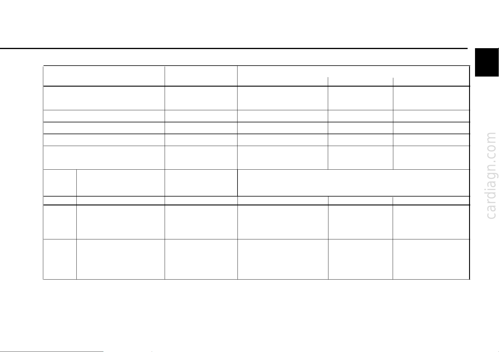
6.1.1.1 Lube oil change intervals for installed engines
Lube oil quality
Deutz lube oil quality class DQ C I- 02 DQ C II -0 5 DQ C III-05 DQC iV-05
ACEA specification E2-96 E3-96/E5-02/E07-04 E4-99/E6-04 E4-99/E6-04
see 6 .1.1.3 only fully synthetic
API specification CF /C F -4 CG- 4/C H-4/ CI- 4 - worldwide specification - DHD-1 - special DEUTZ release list - - see chap. 4.1.2.1 Standard lubricant code designation EO... EO...C - for building machines and building vehicles EO...A, EO...B
Engine Engine version Lube oil change intervals in oh
series
6
TCD All engines with:
2012 Crankcase ventilation:
L04/06 4V open - 500 500 500
closed - - 500 500
2013 Crankcase ventilation:
L04/06 4V open - 500 50 0 500
closed - - 50 0 5 00
© 2005
Page 4

Care and maintenance work 6.1 Lubrication system
cardiagn.com
6
6.1.1. 2 Lube oil change intervals for vehicle engines
Lube oil quality
Deutz lube oil quality class DQ C I- 02 DQ C II -0 5 DQC III-05 DQC iV-05
ACEA specification E2-96 E3-96/E5-02/E07-04 E4-99/E6-04 E4-99/E6-04
see 6.1 .1.3 only fully
synthetic
API specification CF /C F -4 CG- 4/C H-4/ CI- 4 - worldwide specification - DHD-1 - special DEUTZ release list - - see chap. 4.1.2.1 -
Application
Building site
vehicles /
city buses/ Coach bus clo se d - 30 000 50 000 50 000
City TCD 2013 L04 4V clo se d - 25 000 45 000 45 000
transport TCD 2013 L06 4V close d - 30 000 50 000 50 000
Local transport 40 TCD 2013 L04 4V close d - 40 000 60 000 60 000
average driving speed km/h
Long distance
transport
© 2005
Engine version Crankcase
TCD 2012/2013 L04/ 06 4V ventilation Lube oil change intervals in km
TCD
2012 4V open - 20 000 20 000 20 000
clo se d - - 20 000 20 000
TCD 2013 L06 4V
25 Inter city bus cl os e d - 20 000 30 000 30 000
City busbus cl o se d - 15 000 20 000 20 000
TCD
2012 4V open - 30 000 30 000 30 000
clo se d - - 30 000 30 000
TCD 2013 L06 4V close d - 50 000 75 000 75 000
TCD
2012 4V open - 40 000 40 000 40 000
60 clo se d - - 40 000 40 000
TCD 2013 L04 4V close d - 60 000 80 000 80 000
TCD 2013 L06 4V closed - 75 000 100 000 100 000
Page 5
6.1 Lubrication system Care and maintenance work
cardiagn.com
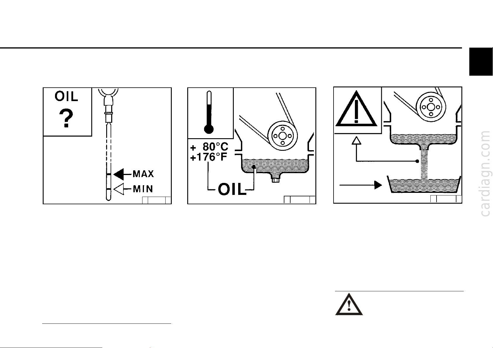
6.1.2 Checking oil level / changing
engine oil
6.1.2.1Checking oil level
© 25 729 0
z Position the engine or vehicle so as to be level.
z – Engine warm:
Switch off the engine, wait for 5 minutes and
check oil level.
z – Engine cold:
Check oil level.
z Extract oil dipstick.
z Wipe with a fibre-free, clean cloth.
z Insert until it stops and extract again.
z Check oil level and re-fill to „MAX“ if necessary.
– If the oil level lies just above the „MIN“-
line marking, re-filling is necessary.
The oil level may not fall short of the „MIN“ line
marking.
6.1.2.2 Changing engine oil
© 26 022 0
z Warm up engine.
z Position the engine or vehicle so as to be level.
– Lube oil temperature approx. 80 °C.
z Switch off engine.
© 26 023 0
z Position oil drip cup under the engine.
z Unscrew oil drain screw.
z Drain off oil.
z Screw in oil drain screw with new sealing ring
and tighten. (For tightening torque
see 9.2).
z Pour in lube oil.
– For quality / viscosity data see 4.1.
– For filling quantities, see 9.1.
z Check oil level, see 6.1.2.1.
Caution when draining
hot oil: danger of scalding!
Collect the used oil, do not allow to
seep into floor!
Dispose of according to instructions!
6
© 2005
Page 6
6
cardiagn.com
Care and maintenance work 6.1 Lubrication system
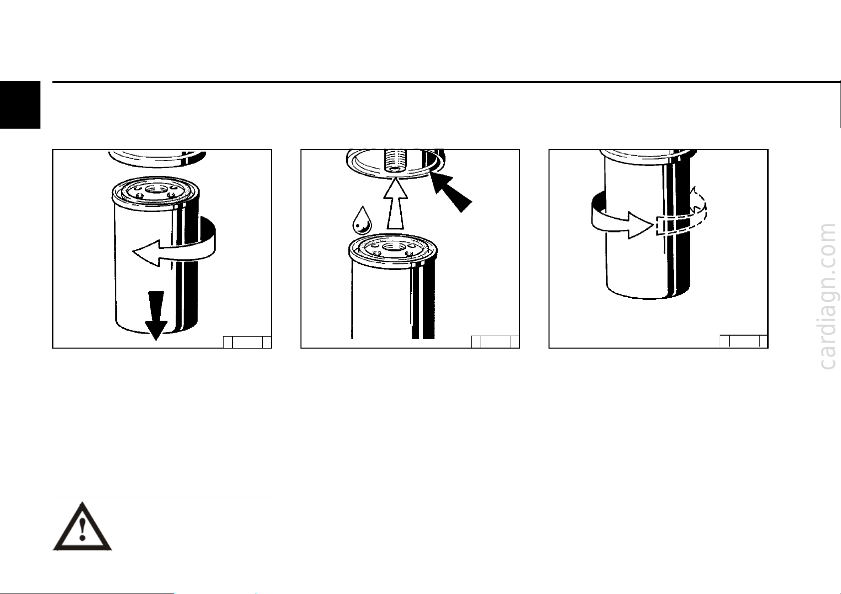
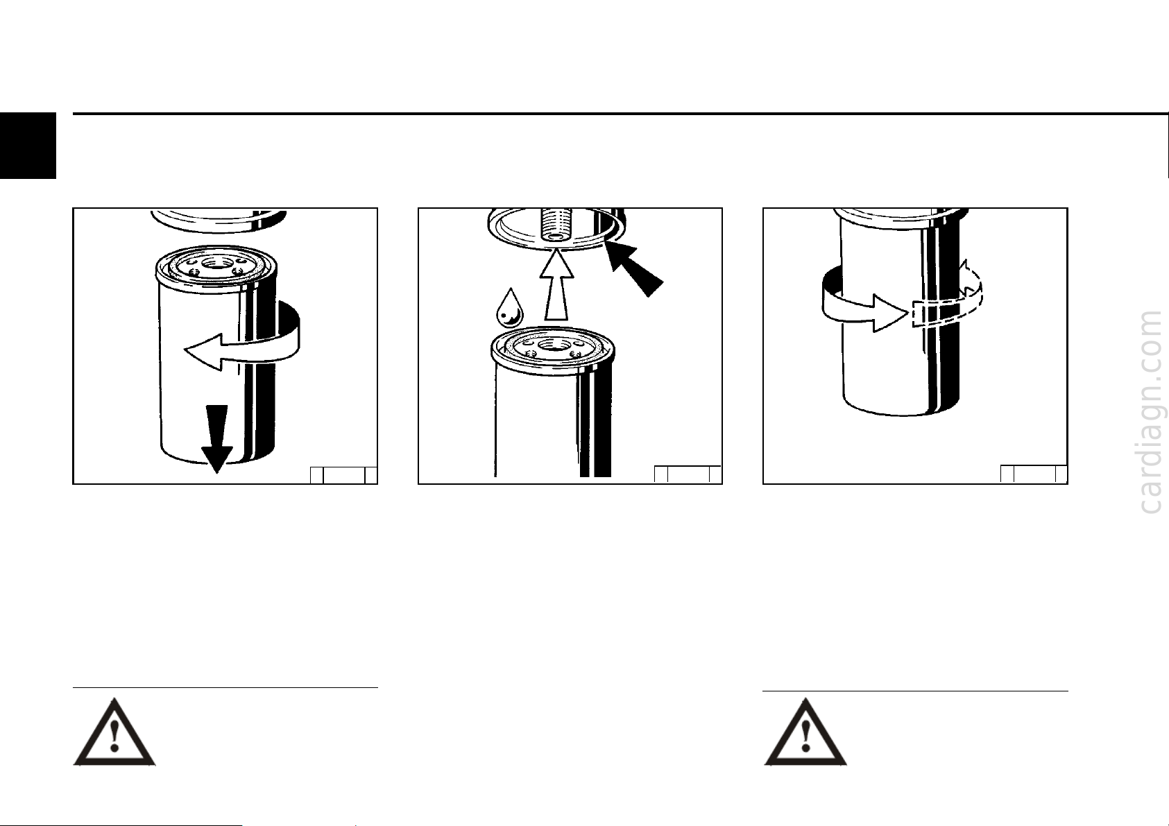
6.1.3 Changing oil filter insert
z When anti-rotation lock is installed:
Loosen clamping screws and remove tightening clamps from below.
z Loosen lube oil filter cartridge with stan-
dard tool and unscrew.
z Collect any oil which may run out.
Careful with hot oil:
danger of scalding!
© 2005
© 25 880 0
© 25 881 0
z Clean the sealing surface of the filter sup-
port for any possible dirt.
z Lightly oil the rubber seal of the new lube
oil cartridge.
z Screw on the cartridge by hand until the
seal makes contact.
© 25 88 2 0
z Tighten lube oil filter cartridge three quarters
of a turn (approx. 10 Nm).
z If there is an anti-rotation lock:
Position the tightening clamps and tighten
with clamping screws.
z Check oil level, see 6.1.2.
z Check oil pressure, see 3.3.1.
z Check the seal of the lube oil filter cartridge
for tightness.
Page 7
6.1 Lubrication system Care and maintenance work
cardiagn.com
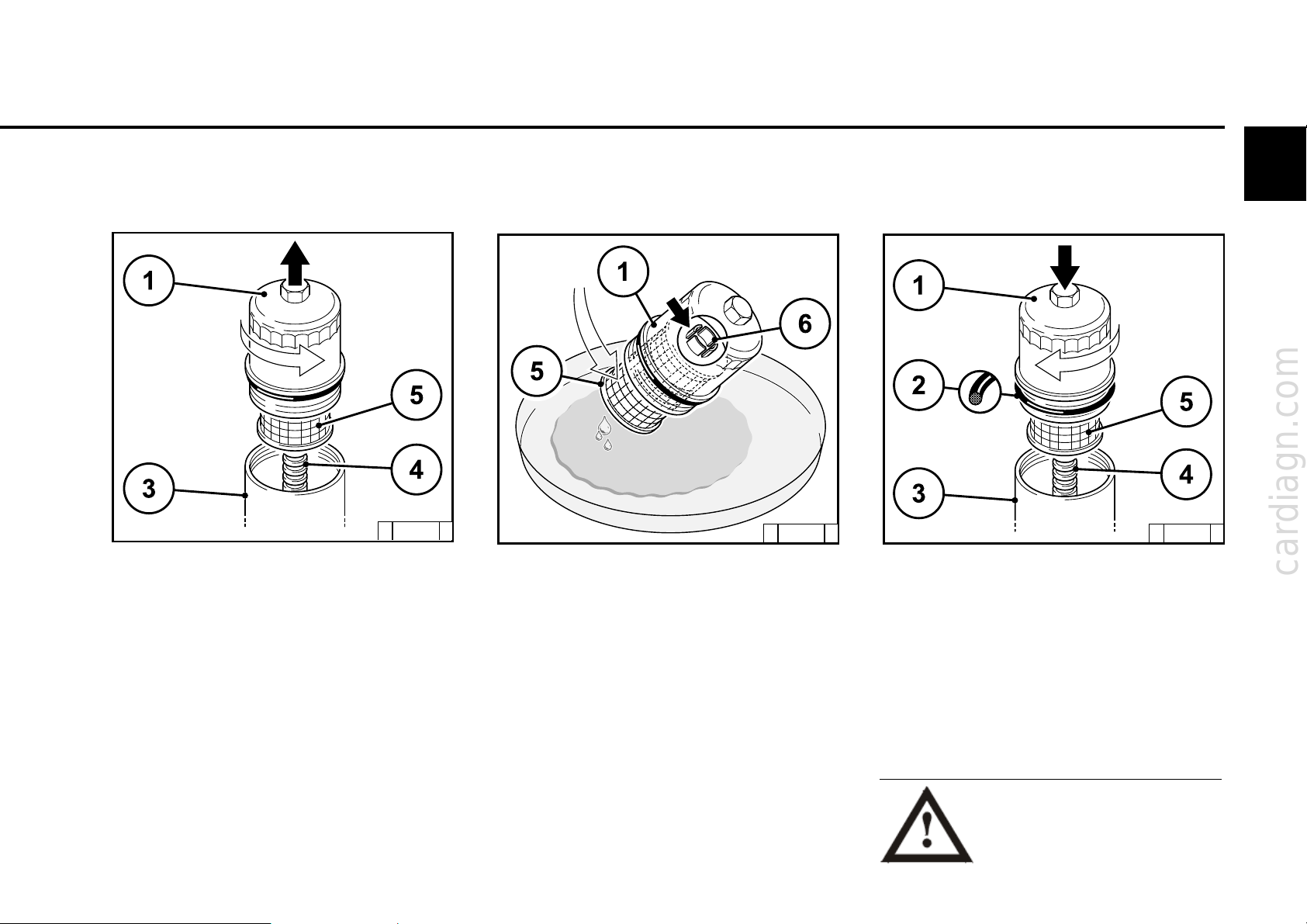
6.1.4 Cleaning / changing oil filter
(cup)
6
z Switch off engine.
z Loosen lube oil filter cover 1 with two or three
turns and wait for 30 seconds.
z Unscrew lube oil filter cover 1 with paper filter
cartridge 5 in anti-clockwise direction.
z Carefully loosen paper filter cartridge 5 from
the guide 4, which is inserted in the housing 3,
from above.
© 30 0 74 1
© 43 937 0 © 300 74 0
z Collect any lube oil which may run out.
z Crease the paper filter cartridge 5 in the
collection vessel slightly at the side until the
cartridge is released from the clip 6.
z Clean the sealing surface of the filter support
and the lube oil filter cover 1 as well as the guide
4 of any dirt there may be
z Change the round sealing ring 2 and lightly oil.
z Press new paper filter cartridge 5 into the clip
6 and insert carefully in the guide 4 together.
z Screw the lube oil filter cover 1 tight in clock-
wise direction (25 Nm).
z Start the engine.
z Check lube oil filter assembly for leaks.
z Check engine oil level and top up if necessary.
Careful with hot oil:
Danger of scalding
Dispose of used oil in an
environmentally friendly way.
© 2005
Page 8
Care and maintenance work 6.2 Fuel system
cardiagn.com
6
6.2.1 Changing fuel filter
© 25 880 0
z Close fuel stopcock.
z Loosen fuel filter cartridge with standard tool
and unscrew.
z Collect any fuel which may run out.
z Clean the sealing surface of the filter support
for any dirt there may be.
z Lightly oil the rubber seal of the new DEUTZ
original fuel filter cartridge or wet with diesel
fuel.
© 25 881 0
z Screw on the cartridge by hand until the seal
makes contact.
z Tighten the fuel filter cartridge with one more
half turn.
z Open fuel stopcock.
z Check for tightness.
© 25 882 0
Only work on the fuel system
when the engine is switched off.
Wait at least 30 seconds. No open
fire! Do not smoke!
© 2005
Pay attention to cleanliness as the
fuel system (Rail) is very sensitive!!!
It is necessary to bleed the fuel
system.
Page 9

6.2 Fuel system Care and maintenance work
cardiagn.com
6.2.2 Cleaning / changing fuel filter
(cup)
© 300 74 0
z Switch off engine
z Loosen fuel filter cover 1 and unscrew in anti-
clockwise direction.
z Carefully loosen paper filter cartridge 3 from
the guide 4 from above.
z Collect any fuel which may run out.
z Change paper filter cartridge 3.
z Clean the sealing surface of the filter support
and the fuel filter cover 1 as well as the guide4
of any dirt there may be.
6
z Change the rubber seal 2 and lightly oil.
z Carefully place new paper filter cartridge 3 in
the guide 4.
z Tighten the fuel filter cover 1 in clockwise
direction (25 Nm).
z Start engine.
z Check fuel filter attachment for tightness.
Only work on the fuel system
when the engine is switched off
(at least 30 seconds).
No open fire! Do not smoke!
Dispose of used fuel in an
environmentally friendly
manner.
© 2005
Page 10

Care and maintenance work 6.2 Fuel system
cardiagn.com
6
6.2.3 Changing / bleeding
fuel pre-filter , filter insert
© 43 848 1
Filter change:
z Close fuel stopcock (for high tanks).
z Position fuel collecting vessel beneath fuel pre-filter.
z Loosen drain cock (7) and drain water + fuel
completely .
z Unscrew filter cartridge (5) together with
water collecting vessel (8) in anti-clockwise
direction and remove.
z Loosen water collecting vessel (8) from old
filter cartridge (5) in anti-clockwise direction
and remove.
z Empty remaining fuel into the fuel collecting
vessel and clean water collectingvessel (8).
z Screw water collecting vessel (8) onto the
new filter cartridge (5) in clockwise direction.
© 2005
z Clean any dirt from the sealing surface of the
new filter cartridge (5) and the reverse side
of the filter head
z Wet the sealing surfaces of the filter cartridge
(5) slightly with fuel and screw back onto the
filter head in clockwise direction (17-18 Nm)
z Open the fuel stopcock and bleed the system
(see „Bleeding fuel system“).
z Dispose of collected fuel and old filter cartridge
(5) properly.
Bleeding fuel system:
z Unlock the bayonet plug of the fuel hand
pump (3) by pressing and turning
anti-clockwise at the same time. The pump
plunger is now pushed out through the spring.
Turn the shutdown lever of the ther-
mostat valve (4) by approx. 45° in
clockwise direction until it is felt to
engage.
z Pump until a very strong resistance is felt and
pumping becomes very slow.
z Now pump a few more times.
(The return line must be filled).
z Turn the shutdown lever of the thermostat
valve (4) by approx. 45° in anti-clockwise
direction until it is felt to engage.
z Lock the bayonet plug of the fuel hand pump
(3) by pressing and turning clockwise at the
same time.
1 Fuel supply to pump
2 Fuel return from control block FCU
Fuel Control Unit)
(
3 Fuel hand pump with bayonet plugfor
locking and unlocking
4 Thermostat valve with shutdown lever
5 Filter cartridge
6 Connection facility for electrical
water level sensor
7 Drain cock
8 Water collecting vessel (bowl)
9 Fuel inlet from fuel tank
10 Fuel return to fuel tank
Only work on the fuel system
when the engine is switched off.
No open fire! Do not smoke!
Dispose of used fuel in an
environmentally friendly manner.
Page 11

6.3 Cooling system Care and maintenance work
cardiagn.com
6.3.1 Cleaning intervals
z The cooling system soiling depends on the
type of engine application.
z The risk of soiling is increased by oil and fuel
residues on the engine. Therefore pay particular
attention to tightness when operating under
high dust exposure.
z Increased soiling occurs, for example, during:
- Building site application from high dust content
of air.
- Harvesting application from high proportion of
chaff and chopped straw , for example, in the
area of the work machine.
z Due to the various application conditions, the
cleaning intervals must be defined according
to each case. Therefore, the cleaning intervals
given in the table below can be used as
guidelines.
Checking or cleaning intervals
Guideline oh
2000 Ships, electronic units in
1000 Vehicles on paved
500 Tractors, fork lift trucks, drivable
250 Vehicles on building sites and
125 Agricultural machinery, tractors
Engine application
enclosed spaces, pumps.
roads
electronic units.
unpaved roads, building
machines, compressors, mining
equipment.
with harvesting application.
6
© 2005
Page 12

Care and maintenance work 6.3 Cooling system
cardiagn.com
6
6.3.2 Cleaning cooling system
©39 0010
Cleaning with compressed air
- Blast out the engine wih compressed air. Do not
damage any components.
- Rinse out the loosened dirt with a water jet.
© 39 002 0
Cleaning with cold cleaner
- Spray the engine with standard cold cleaner
and leave to work for approx. 10 minutes.
- Spray the engine clean with an acute water jet
(do not spray the water jet directly at sensitive
engine parts, e.g. generator, cabling, electronic
components, fan drive).
© 38 999 0
© 2005
Page 13

6.3 Cooling system Care and maintenance work
cardiagn.com
6.3.3 Emptying / filling / bleeding
cooling system
6
Emptying cooling system:
z Position collecting dish underneath locking
screw 5 and coolant supply 4.
z Remove locking screw 5 on the crankcase
and pull off hose on 4.
z Loosen bleed screw 2.
z Drain off coolant.
z Re-tighten locking screw 5 and hose on 4 and
bleed screw 2.
z If locking screw 3 is not accessible,
emptying may be carried out on the engine
oil cooler (coolant channel).
Filling / bleeding cooling system:
z Open cooler cover.
z Loosen bleed screw item 2.
z Pour in coolant until the maximum mark or the filling
limit (system heating valve must be open, if
present).
z Tighten bleed screw item 2 + locking screw
item 5.
zClose cooler cover.
zStart engine and warm up until the thermostat opens.
zSwitch off engine.
zCheck the coolant level with the engine cold and
re-fill if necessary.
zClose cooler cover item 1.
Bleeding
zThe cooling system, which was built according
to our installation guides, is bled automatically
after filling.
© 39 851 0
Caution when draining hot coolant:
danger of scalding! Collect coolant
when draining off.
Dispose of according to
instructions!
© 2005
Page 14

Care and maintenance work 6.4Combustion air filter
cardiagn.com
6
6.4.1 Cleaning intervals
z The soiling of the combustion air filter
depends on the dust content of the air and
the selected filter size. If a high dust
exposure is to be expected, a cyclone
separator can be connected to the
combustion air filter.
z The cleaning intervals cannot be generally
defined. They must be defined depending
on each case.
z If dry air filters are used, cleaning should only
be carried out according to the maintenance
display or maintenance switch.
z Filter maintenance is required when on the:
- Maintenance display
the red service field 1 is fully
visible when the engine is not running.
- Maintenance switch
the yellow warning light comes on when
the engine is running.
© 25 885 1
z After completion of the maintenance work
push the reset button on the maintenance
display. The maintenance display is ready
for operation again.
© 2005
Page 15

6.4 Combustion air filter Care and maintenance work
cardiagn.com
6.4.2 Emptying cyclone preseparator
© 25 886 0
z Loosen wing nut 1 and lift housing cover 2.
z Remove the dust container 3 from the base of
the cyclone 4 and empty . Clean foliage, straw
and the like from the cylone base.
z Place the dust container 3 on the base 4 and
tighten the housing cover 2 with wing nut 1.
6
Never fill the dust container with oil, replace
damaged containers!
© 2005
Page 16

Care and maintenance work 6.4 Combustion air filter
cardiagn.com
6
6.4.3 Dry air filter
Dust discharge valve
© 25 888 2
z Empty the dust discharge valve 1 by squeezing
the discharge slot in the direction of the arrow.
z Clean the discharge slot occasionally.
z Remove any stuck on dust residues by
squeezing the upper area of the valve.
Filter cartridge
© 25 889 1
z Open clamping bracket 1.
z Remove filter hood 2 and pull out filter cartridge 3.
z Clean filter cartridge, renew after a year at the latest.
z Clean filter cartridge 3.
- Blast out from the inside out with dry
compressed air (max. 5 bar), or
- beat out (only in extreme cases). Do not
damage the cartridge, or
- Wash according to manufacturer’s
specifications.
z Check filter cartridge for damage to the filter
paper (shine light through) and check seals.
Exchange if necessary.
z Renew the safety cartridge 4 after 5 filter
maintenances, after 2 years at the latest
(never clean!).
To do this:
- Loosen the hexagonal nut 5 and pull out
the cartridge 4.
- Insert new cartridge, re-mount hexagonal
nut and tighten.
z Insert filter cartridge 3, close hood 2 and
secure clamping bracket 1.
Never clean filter cartridge with
petrol or hot liquids!
© 2005
Page 17

6.5 Belt drive Care and Maintenance work
cardiagn.com
6.5.1 Changing V-belt
V -rib belt
© 39 004 0
z Push tension pulley in the direction of the arrow
until V-rib belt is free.
z First remove the V-rib belt from the smallest
pulley .
z Put on new V-rib belt
z Loosen tension pulley in the opposite direction
of the arrow until the V-rib belt is taut
Whilst doing this, check that the V-rib belt is
positioned correctly in your guide.
6.5 . 2 Changing V-belt
V-rib belt
© 39 005 0
z Push tension pulley in the direction of the arrow
until V-rib belt is free.
z First remove the V-rib belt from the smallest pulley.
z Put on new V-rib belt
z Loosen tension pulley in the opposite direction
of the arrow until the V-rib belt is taut Whilst
doing this, check that the V-rib belt is
positioned correctly in your guide.
6.5 .3Checking V-rib belt
wear limit
© 43 851 0
z The wear limit of the V-rib belt is checked as
follows:
z Check the distance between the projection
of the moving tension arm and the contact
with the fixed tensioner housing.
z If „ a“ i s le ss t han 3 mm the V-rib belt should be
changed.
6
Only check/tighten/change Vbelts when the engine is not
running. If necessary, re-mount
V-belt guard.
© 2005
Page 18

6
cardiagn.com
Care and maintenance work 6.6 Setting work
6.6.1 Checking valve clearance,
setting if necessary
z Loosen bleed valve and swing aside.
z Remove cylinder head cover.
z Before setting the valve clearance allow the
engine to cool down for at least 30 minutes: Oil
temperature below 80 °C.
z Place the turning device over the fastening
screws of the belt pulley.
z Turn over engine until the valve overlap is
achieved, cylinder no. 1
z Crankshaft setting as per setting diagram, see
6.6.1.1.
Note: Valve overlap means:
Exhaust valve is not yet closed. Inlet valve
begins to open. For valve setting diagram see
6.6.1.1, the table on the right.
© 2005
© 38 995 0
© 38 996 0
Setting instructions:
IN= inlet valve
EX = exhaust valve
z Perform test and setting work on every cylinder.
z Re-mount cylinder head cover (if necessary
with new gasket).
z Swing the bleed valve into position and fasten
Example: BF4M 2013
Valve clearance setting
1. Work step 1. Set cylinder to overlap, set cylinder 4.
2. Work step 3. Set cylinder to overlap, set cylinder 2.
3. Work step 4. Set cylinder to overlap, set cylinder 1.
4. Work step 2. Set cylinder to overlap, set cylinder 3.
Page 19

6.6 Setting work Care and maintenance work
cardiagn.com
6.6.1.1 Valve clearance setting diagram
Setting the valves: (black identification
z Perform valve clearance setting on appropria-
te cylinder with valve clearance setting device
part no. 8190.
Loosen all lock nuts 2 of the rocker arm
assembly to be set. Turn setting screw 1 back
with the valve clearance setting device one
turn in anti-clockwise direction.
On the valve to be set, turn setting screw 1 in
clockwise direction so as to be free of clearance.
That means, there must not be any clearance
between the rocker arm and valve and no
pressure may be applied to the valve.
z Set needle of measuring plate to [i| , not
twisting the knurled handle any more.
z Hold the measuring plate exactly in this position
and turn the setting screw 1 in anti-clockwise
direction with the knurled handle until the
needle is on the „in“ or „ex“ marking.
z Hold the knurled handle exactly in this position and
tighten lock nut 2 with a torque wrench (20 Nm).
z Üput on seal (poss. new seal).
z Visual inspection of screws and rubber ele-
ments, renew if necessary.
z Put on valve mechanism cover and tighten
screws according to tightening specification:
9 Nm (see 9.2).
)
6
© 38 997 0
© 2005
Page 20

Care and maintenance work 6.6 Setting work
cardiagn.com
6
6.6.2 Checking control piston
clearance at engine brake,
setting if necessary
© 43 935 0
z After the valve clearance has been set.
- Control unit for engine brake is already
mounted.
z Set the clearance on the control unit as follows.
z Turn engine until reaching the valve overlap
is reached, cylinder no. 1
z Set control piston clearance on every exhaust
valve.
z Proceed as for valve clearance.
Note
Valve overlap means:
Exhaust valve is not yet closed. Inlet valve begins
to open, see valve setting diagram.
© 2005
© 43 936 0
z Set control piston clearance if necessary, by:
- Loosening the lock nut 2.
- Mount the control piston clearance X on
setting screw 1 (see 6.6.1) with setting device
in EX and set as follows:
Fix the magnet
Turn th e set ting devic e without clearance
until the control piston contacts with the valve
bridge, set scale to „0“.
Then turn back angle degree 432° (by
hand or torque wrench):
EX = exhaust valve 432° for M8 thread
(corresponds to 1.5 mm clearance)
- Tighten lock nut 4.
z Perform test and setting work on every
cylinder.
z Replace cylinder head cover (if necessary
with new gasket).
z Swing the bleed valve into position and
fasten.
IN = Inlet valve
EX = Exhaust valve
1 Setting screw
2 Lock nut
3 Solenoid valve (electronic control)
4 Control board
Page 21

6
cardiagn.com
© 2005
Page 22

Care and maintenance work 6.7 Add-on parts
cardiagn.com
6
6.7.1.1Testing battery and cable
connections
© 25 895 0
z Keep the battery clean and dry.
z Loosen soiled connection terminals.
z Clean the battery poles (+ and -) and terminals,
and grease with an acid-free and acid-resistant
grease.
z Ensure that the terminal connections contact
well when assembling. Tighten the clamping
screws by hand.
6.7.1.2 Checking the acid level
© 24 232 3 © 25 896 0
z Remove sealing cap 1.
z If checking inserts 2 are available:
The liquid level should reach to their bottom.
z Without checking inserts:
The liquid level should reach 10-15 mm above
the upper edge of the plate.
z If necessary, re-fill with distilled water.
z Screw sealing cap back on.
6.7.1.3 Checking acid density
z Measure the acid density of individual cells
with a standard acid testing device.
The measured values (see table overleaf)
indicate the charge status of the battery. The
acid temperature when measuring should be
20 °C if possible.
© 2005
Page 23

6.7 Add-on parts Care and maintenance work
cardiagn.com
Acid density
in [kg/ l]
in [°Bé (Baumé degree)*] Charg e leve l
6
Normal
1,28
1,20
1,12
* The data for acid density in °Bé
(Baumé degree) is out of date and rarely
still in use.
Tropics
1,23
1,12
1,08
The gases released by the battery
are explosive! Avoid sparks and
open fire in the vicinity of the
battery! Do not allow acid to get on
skin or clothes!
Wear protective glasses!
Do not place any tools on the
battery!
Normal
32
24
16
Tropics
27
16
11
well charged
half charged, re-charge
discharged, charge immediately
© 2005
Page 24

Care and maintenance work 6.7 Add-on parts
cardiagn.com
6
6.7.2 Three-phase current
generator
Notes on three-phase current system:
z Do not interrupt the connections between the
battery, generator and governor when the
engine is running.
z If, however, an engine must be started and
operated without battery, the connection
governor / generator is to be separated before
starting.
z Do not swap battery connections.
z Replace defective charging warning light
immediately .
z When cleaning engine: Do not spray water/
steam jet directly at generator!
lWarm up the engine so that the water residues
evaporate.
z Under no circumstances may the voltage of a
three-phase current system be tested by
tapping against the earth cable.
6.7.3 Transportation suspension
z Only use the correct suspension equipment
for engine transportation. Suspension
equipment must be adjustable for the engine
centre of gravity.
© 38 9943 0© 38 994 0
z Fastening devices cannot be fixed safely over
the centre of gravity.
z Fastening devices can slip, engine capsizes.
z Short fastening devices cause bending
moments in the suspension. This can damage
the suspension.
z When carrying out electrical welding work,
clamp the earth terminal of the welding device
directly to the part to be clamped.
© 2005
Only use correct suspension
equipment!
Engine can fall.
Danger to life!
 Loading...