

Page 1
INSTRUCTION MANUAL
Detcon Model TP-524D-HRT
PGM 1
MODEL TP-524DHOUSTON,TEXAS
TM
MicroSafe H2S Gas Sensor
ALM ALM
FLT 1 2 CAL
PGM 2
TP-524D-HRT Hydrogen Sulfide Sensor
This manual covers the following ranges:
0-20ppm, 0-50ppm, and 0-100ppm
DETCON, Inc.
4055 Technology Forest Blvd, Suite 100,
The Woodlands, Texas 77381
Ph.281.367.4100 / Fax 281.298.2868
www.detcon.com
March 10, 2014 • Document #3602 • Revision 0.3
Page 2

This page left intentionally blank
Model TP-524D-HRT
Shipping Address: 4055 TechnologyForest Blvd, Suite 100, The Woodlands Texas 77381
Phone: 888.367.4286, 281.367.4100 • Fax: 281.292.2860 • www.detcon.com • sales@detcon.com
Model TP-524D-HRT ii
Mailing Address: P.O. Box 8067, The Woodlands Texas 77387-8067
Page 3

Model TP-524D-HRT
Table of Contents
1. Introduction ..................................................................................................................................................1
1.1 Description.......................................................................................................................................... 1
1.2 Modular Mechanical Design............................................................................................................... 2
2. Installation....................................................................................................................................................4
2.1 Operational Guidelines for Safe Use .................................................................................................. 4
2.2 Sensor Placement................................................................................................................................ 4
2.3 Sensor Contaminants and Interference ............................................................................................... 5
2.4 Mounting Installation.......................................................................................................................... 6
2.5 Electrical Installation.......................................................................................................................... 7
2.6 Field Wiring........................................................................................................................................ 8
2.7 Initial Start Up..................................................................................................................................... 9
3. Operation....................................................................................................................................................11
3.1 Programming Magnet Operating Instructions................................................................................... 11
3.2 Operator Interface............................................................................................................................. 12
3.3 Normal Operation ............................................................................................................................. 14
3.4 Calibration Mode (AutoSpan)........................................................................................................... 14
3.5 Program Mode .................................................................................................................................. 16
3.5.1 View Sensor Status....................................................................................................................... 16
3.5.2 Set AutoSpan Level...................................................................................................................... 18
3.5.3 Set Range...................................................................................................................................... 18
3.5.4 Set Heater Power.......................................................................................................................... 19
3.5.5 Signal Output Check..................................................................................................................... 20
3.5.6 Restore Factory Defaults.............................................................................................................. 20
3.5.7 Alarm 1 and 2 Settings ................................................................................................................. 21
3.5.8 Fault Settings................................................................................................................................ 21
3.6 Program Features.............................................................................................................................. 22
3.6.1 Operational Features..................................................................................................................... 22
3.6.2 Fault Diagnostic/Failsafe Features ............................................................................................... 22
4. HRT Bridge................................................................................................................................................25
4.1 Description........................................................................................................................................ 25
4.2 Connecting the HRT Bridge ............................................................................................................. 25
4.3 Operation .......................................................................................................................................... 25
4.4 Operator Interface............................................................................................................................. 26
4.4.1 Device Menu................................................................................................................................. 26
4.4.2 Diagnostics Menu......................................................................................................................... 29
4.4.3 Device Setup Menu ...................................................................................................................... 30
5. Service and Maintenance............................................................................................................................37
6. Troubleshooting Guide...............................................................................................................................39
7. Customer Support and Service Policy........................................................................................................42
8. TP-524D-HRT Sensor Warranty................................................................................................................43
9. Appendix ....................................................................................................................................................44
9.1 Specifications.................................................................................................................................... 44
9.2 Spare Parts, Sensor Accessories, Calibration Equipment................................................................. 46
9.3 Revision Log..................................................................................................................................... 47
Model TP-524D-HRT iii
Page 4

Model TP-524D-HRT
Table of Figures
Figure 1 Sensor Assembly Front View ................................................................................................................ 1
Figure 2 Circuit Functional Block Diagram......................................................................................................... 2
Figure 3 Transmitter Module ............................................................................................................................... 2
Figure 4 Field Replaceable H2S Sensor................................................................................................................ 3
Figure 5 Base Connector Board ........................................................................................................................... 3
Figure 6 Typical Outline and Mounting Dimensions........................................................................................... 7
Figure 7 Typical Installation ................................................................................................................................ 8
Figure 8 Sensor Connector PCB........................................................................................................................... 9
Figure 9 Magnetic Programming Tool............................................................................................................... 11
Figure 10 Magnetic Programming Switches...................................................................................................... 11
Figure 11 TP-524D-HRT Software Flowchart................................................................................................... 13
Figure 12 Primary Variables .............................................................................................................................. 27
Figure 13 Identification...................................................................................................................................... 28
Figure 14 Device Status Screen.......................................................................................................................... 29
Figure 15 FP Configuration Setup...................................................................................................................... 31
Figure 16 FP Calibration Screen ........................................................................................................................ 32
Figure 17 DVM Connection............................................................................................................................... 34
Figure 18 HART Setup....................................................................................................................................... 36
Figure 19 Replaceable H2S Sensor..................................................................................................................... 39
List of Tables
Table 1 Cross Interference Gases......................................................................................................................... 6
Table 2 Wire Gauge vs. Distance......................................................................................................................... 8
Shipping Address: 4055 TechnologyForest Blvd, Suite 100, The Woodlands Texas 77381
Phone: 888.367.4286, 281.367.4100 • Fax: 281.292.2860 • www.detcon.com • sales@detcon.com
Model TP-524D-HRT iv
Mailing Address: P.O. Box 8067, The Woodlands Texas 77387-8067
Page 5

Model TP-524D-HRT
1. Introduction
1.1 Description
Detcon Model TP-524D-HRT hydrogen sulfide sensors are non-intrusive “Smart” sensors designed to detect
and monitor H2S in air. Ranges of detection are 0-20ppm, 0-50ppm, and 0-100ppm. The sensor features an
LED display of current reading, fault, and calibration status. The Sensor is equipped with a HRT Bridge
Interface, analog 4-20mA output. The HRT Bridge interface provides bi-directional digital communication
with HART®-enabled devices. A primary feature of the sensor is its method of automatic calibration, which
guides the user through each step via fully scripted instructions displayed on the LED display.
The microprocessor-supervised electronics are packaged as a plug-in replaceable Transmitter Module that is
housed in an explosion proof junction box. The Transmitter Module includes a four character alpha/numeric
LED used to display sensor readings, and the sensor’s menu driven features when the hand-held programming
magnet is used.
PGM 1
MODEL TP-524DHOUSTON,TEXAS
TM
MicroSafe H2S Gas Sensor
ALM ALM
FLT 1 2 CAL
PGM 2
Figure 1 Sensor Assembly Front View
Solid State H2S Sensor Technology
The sensor technology is a patented solid-state mixed metal oxide semiconductor.
The sensor consists of two thin films, a temperature sensitive heater film, and a
hydrogen sulfide sensitive sensor film. Both films are deposited on a silicon
microchip by vacuum deposition. The heater film elevates the operating
temperature of the sensor film to a level where a good sensitivity and response to
hydrogen sulfide is achieved. The sensor film is a proprietary mixed metal oxide
that shows an extremely stable and dynamic response to hydrogen sulfide gas.
Range of sensitivity is from parts per billion to percent by volume. The rugged
sensor is capable of maintaining its operating characteristics for periods of up to 710 years in most industrial environments and as such, is supported by a 10-year
conditional warranty.
TP-524D-HRT Instruction Manual Rev. 0.3 Page 1 of 48
Page 6
Model TP-524D-HRT
RS-4854-
20mA
Display
Control
Pre-Amp
Power Supply
Principle of Operation
Method of detection is by diffusion/adsorption. Air and H2S diffuse through a sintered stainless steel filter
(flame arrestor) and contact the heated surface of the metal oxide sensor film. As hydrogen sulfide gas
molecules react with oxygen ions on the film, there is a decrease in electrical resistance proportional to the gas
concentration. The heater film elevates the temperature of the sensor film creating convection and promoting
a quick response to changing gas concentrations. Electronically, the heater film is used to maintain a constant
temperature of the sensor film enhancing stability and repeatability. The sensor response is reversible and
results in continuous monitoring of ambient air conditions.
1.2 Modular Mechanical Design
The Model TP-524D-HRT Sensor Assembly is completely modular and is made up of four parts:
1) TP-524D with HRT Brifge Plug-in Transmitter
2) Field Replaceable H2S Gas Sensor
3) Connector PCB
4) Splash Guard.
TP-524D-HRT Plug-in Transmitter
The Plug-in Transmitter Module is a microprocessor-based package that plugs into the connector board located
in the explosion proof junction box. Circuit functions include extensive I/O circuit protection, sensor preamplifier, sensor temperature control, on-board power supplies, microprocessor, LED display, magnetic
programming switches, and a linear 4-20mA DC output. Magnetic program switches located on either side of
the LED Display are activated via a hand-held magnetic programming tool, thus allowing non-intrusive
operator interface with the Transmitter Module. Calibration can be accomplished without declassifying the
area. Electrical classifications are Class I, Division 1, Groups B C D.
Plug-In
Sensor
Element
Temperature
Micro-
Processor
I/O
Circuit
Protection
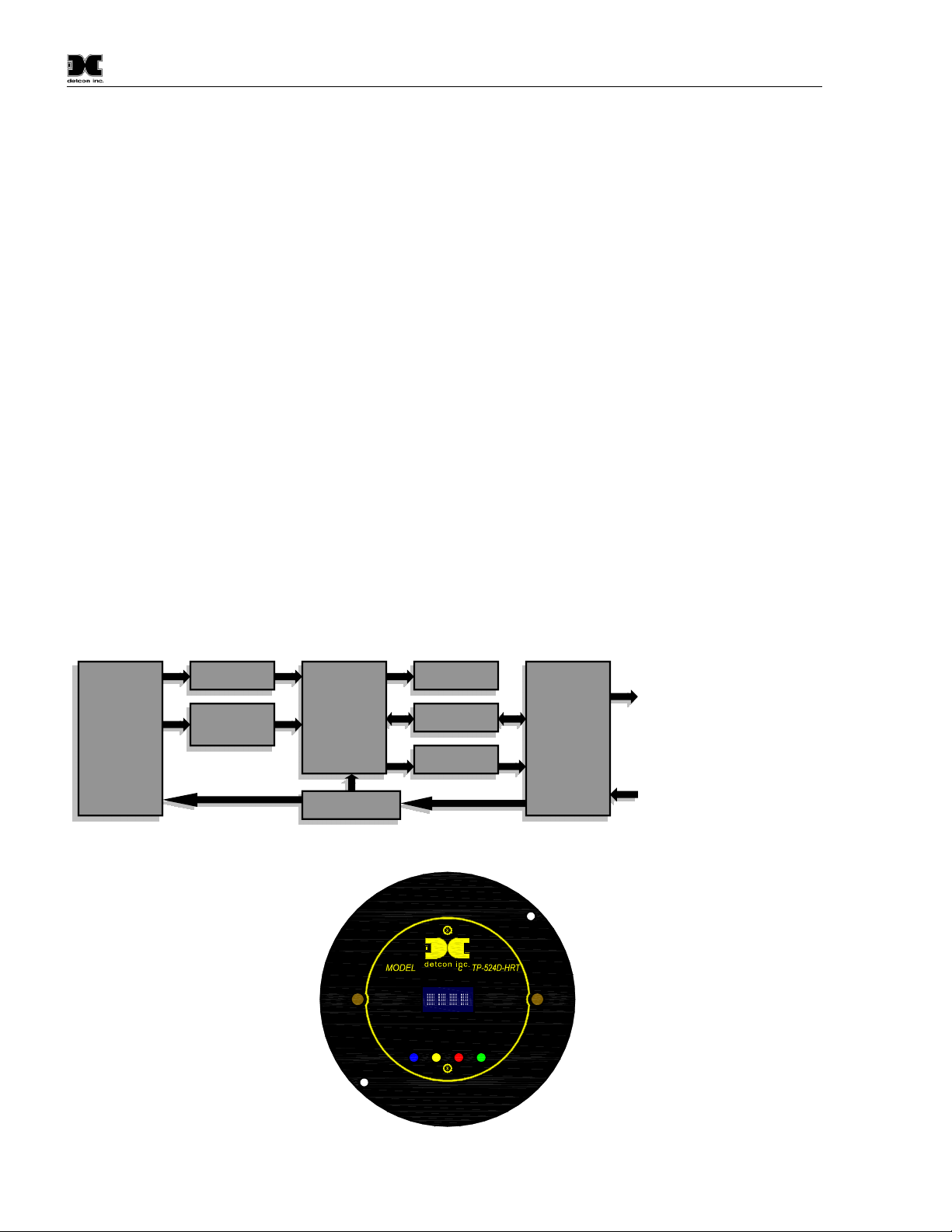
Figure 2 Circuit Functional Block Diagram
PGM 1
HOUSTON,TEXAS
TM
MicroSafe H2S Gas Sensor
ALM ALM
FLT 1 2 CAL
PGM 2
Figure 3 Transmitter Module
Analog 4-20mA Out
HART Communication
Power In
TP-524D-HRT Instruction Manual Rev. 0.3 Page 2 of 48
Page 7
Model TP-524D-HRT
Field Replaceable Sensor
The Detcon solid-state H2S gas sensor is a field proven, replaceable type sensor. It can be accessed and
replaced in the field by removing the wiring from the connector PCB, and unthreading the Sensor from the
junction box. The Detcon solid state H2S sensor has an infinite shelf life and is supported by a 10 year,
industry-leading warranty.
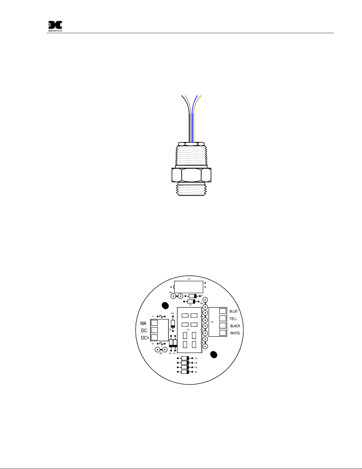
Figure 4 Field Replaceable H2S Sensor
NOTE: The Field Replaceable H2S Gas Sensor is constructed from 316 Stainless Steel in order to maximize
corrosion resistance in harsh environments.
Base Connector PCB
The base connector board is mounted in the Junction Box. The connector board includes Lug less terminal
connections for incoming power and MA output / HART Interface, and connections for the H2S Replaceable
Sensor.
Wiring to
Customer
Wiring
H2S Sensor
Figure 5 Base Connector Board
TP-524D-HRT Instruction Manual Rev. 0.3 Page 3 of 48
Page 8

Model TP-524D-HRT
Note:
2. Installation
2.1 Operational Guidelines for Safe Use
1. Install sensor only in areas with classifications matching with those described on the approval label.
Follow all warnings listed on the label.
2. Ensure that the sensor is properly mounted in a vertical orientation with sensor facing down. Avoid
use of Teflon Tape, or any type of non-conductive pipe thread coating on the NPT threaded
connection.
3. Use ¾” NPT plugs properly rated for hazardous locations to block any unused connections
4. Removal of the Junction box cover or threaded sensor housing (399-800000-000) violates the Ex d
protection method and hence power must be removed from the sensor prior its safe removal.
5. Proper precautions should be taken during installation and maintenance to avoid the build-up of static
charge on the plastic components of the sensor. These include the splashguard and splashguard
adapter.
6. Do not operate the sensor outside of the stated operating temperature limits.
7. Do not operate the sensor outside the stated operating limits for voltage supply.
2.2 Sensor Placement
Selection of sensor location is critical to the overall safe performance of the product. Five factors play an
important role in selection of sensor locations:
(1) Density of the gas to be detected
(2) Most probable leak sources within the industrial process
(3) Ventilation or prevailing wind conditions
(4) Personnel exposure
(5) Maintenance access
(6) Additional Placement Considerations
Density
Placement of sensors relative to the density of the target gas is such that sensors for the detection of heavier
than air gases should be located within 4 feet of grade as these heavy gases will tend to settle in low lying
areas. For gases lighter than air, sensor placement should be 4-8 feet above grade in open areas or in pitched
areas of enclosed spaces.
H2S is heavier than air.
Leak Sources
The most probable leak sources within an industrial process include flanges, valves, and tubing connections of
the sealed type where seals may either fail or wear. Other leak sources are best determined by facility
engineers with experience in similar processes.
Ventilation
TP-524D-HRT Instruction Manual Rev. 0.3 Page 4 of 48
Page 9

Model TP-524D-HRT
NOTE:
Normal ventilation or prevailing wind conditions can dictate efficient location of gas sensors in a manner
where the migration of gas clouds is quickly detected.
Personnel Exposure
The undetected migration of gas clouds should not be allowed to approach concentrated personnel areas such
as control rooms, maintenance or warehouse buildings. A more general and applicable thought toward
selecting sensor location is combining leak source and perimeter protection in the best possible configuration.
Maintenance Access
Consideration should be given to providing easy access for maintenance personnel. Consideration should also
be given to the consequences of close proximity to contaminants that may foul the sensor prematurely.
In all installations the gas sensor should point straight down (refer to Figure 7).
Improper sensor orientation may result in false readings and permanent sensor damage.
Additional Placement Considerations
The sensor should not be positioned where it may be sprayed or coated with surface contaminating substances.
Painting sensor assemblies is prohibited.
Although the sensor is designed to be RFI resistant, it should not be mounted in close proximity to highpowered radio transmitters or similar RFI generating equipment.
When possible mount in an area void of high wind, accumulating dust, rain, or splashing from hose spray,
direct steam releases, and continuous vibration. If the sensor cannot be mounted away from these conditions
then make sure the Detcon Harsh Location Dust Guard accessory is used.
Do not mount in locations where temperatures will exceed the operating temperature limits of the sensor.
Where direct sunlight leads to exceeding the high temperature-operating limit, use a sunshade to help reduce
temperature.
2.3 Sensor Contaminants and Interference
Solid State H2S sensors may be adversely affected by exposure to certain airborne substances. Loss of
sensitivity or corrosion may be gradual if such materials are present in sufficient concentrations.
The more common materials that potentially cause problems with the sensors are as follows:
Silicone vapors such as those found in greases and lubricants
Halide Compounds containing Chlorine, Chlorine Dioxide, Fluorine, HF, HCl, and Bromine
Caustic and Acid liquids and concentrated vapors
Heavy metals such as tetraethyl lead
Heavy and complex VOC gasses
The presence of such contaminants in an area does not preclude the use of this H2S sensor technology,
although it is likely that the sensor lifetime will be shorter as a result. Use of this sensor in these environments
may require more frequent calibration checks to ensure safe system performance.
Solid State H2S sensors require O2in the background gas and the reading is affected by changing O2levels.
Interference Data
TP-524D-HRT Instruction Manual Rev. 0.3 Page 5 of 48
Page 10

Model TP-524D-HRT
NOTE:
NOTE:
NOTE:
There are some gases typically found in industrial environments that can cause a cross-interference response
on the sensor. See the Table below for some examples.
Table 1 Cross Interference Gases
GAS PPM GAS PPM
Methane 25,000 = 0 Ammonia 500 = 1
Ethane 5,000 = 0 Diesel Fuel 1000 = 0
Hexane 5,000 = 0 Dimethyl Sulfide 4.4 = 0
Propane 5,000 = 0 Ethylene 200 = 0
Butane 5,000 = 0 Freon 12 1,000 = 0
Carbon Monoxide 1% = 0 Hydrogen 5% = 0
Carbon Dioxide 5,000 = 0 Methyl Mercaptan 10 = 0
Carbon Disulfide 14 = 0 Sulfur Dioxide 300 = 0
Methanol 500 = 5 Toluene 32 = 0
Isopropanol 500 = 3 Ethanol 500 = 5
The Detcon MOS Sensor Cell can be damaged to the point of non-functioning if the
unit is left off power and in the presence normal air levels of moisture for periods exceeding 8
hours.
Always protect the sensor cell with the Detcon Sealing Cap and a fresh desiccant
packet when the sensor is powered off, this will avoid permanent sensor cell damage and help
preserve the span calibration.
2.4 Mounting Installation
The TP-524D-HRT should be vertically oriented so that the sensor points straight downward. The explosionproof enclosure or junction box would then typically be mounted on a wall or pole (See Figure 6). Detcon
provides a selection of standard junction boxes in both Aluminum and Stainless Steel.
Do not use Teflon Tape or any other type of Pipe Thread material on the ¾” threads
unless the unit is mounted in a severe or harsh environment. Metal-on-metal contact must be
maintained to provide a solid electrical ground path. If Teflon Tape is used the Sensor must be
externally grounded using a ground strap.
When mounting on a pole, secure the Junction Box to a suitable mounting plate and attach the mounting plate
to the pole using U-Bolts. (Pole-Mounting brackets for Detcon Junction Box’s are available separately.)
TP-524D-HRT Instruction Manual Rev. 0.3 Page 6 of 48
Page 11

6.125"
NOTE:
NOTE:
NOTE:
5.5"
PGM 1
MODEL TP-524DHOUSTON,TEXAS
3
NPT Ports
4
Model TP-524D-HRT
4.6"
6.45"
1
" mounting holes
4
TM
MicroSafe H2S Gas Sensor
ALM ALM
FLT 1 2 CAL
PGM 2
5.25"
8-32 tapped
ground point
H2S Sensor
Wall (or other
mounting surface)
2.1"
2"
Splash Guard
Figure 6 Typical Outline and Mounting Dimensions
2.5 Electrical Installation
The Sensor Assembly should be installed in accordance with local electrical codes. The sensor assemblies are
CSA/NRTL approved (US and Canada) for Class I, Division 1, Groups B, C, & D area classifications.
Proper electrical installation of the gas sensor is critical for conformance to Electrical Codes and to avoid
damage due to water leakage. Refer to Figure 7 and Figure 8 for proper electrical installation.
If a conduit run exits the secondary port, repeat the installation technique shown in
Figure 7.
In Figure 7, the drain allows H2O condensation inside the conduit run to safely drain away from the sensor
assembly. The electrical seal fitting is required to meet the National Electrical Code per NEC Article 500-3d
(or Canadian Electrical Code Handbook Part 1 Section 18-154). Requirements for locations of electrical seals
are covered under NEC Article 501-5. Electrical seals also act as a secondary seal to prevent water from
entering the wiring terminal enclosure. However, they are not designed to provide an absolute watertight seal,
especially when used in the vertical orientation.
A conduit seal is typically required to be located within 18" of the J-Box and Sensor
Assembly. Crouse Hinds type EYS2, EYD2 or equivalent are suitable for this purpose.
The Detcon Warranty does not cover water damage resulting from water leaking into
the enclosure.
TP-524D-HRT Instruction Manual Rev. 0.3 Page 7 of 48
Page 12
Conduit
NOTE:
NOTE 1:
NOTE 2:
Model TP-524D-HRT
"T"
Drain
EYS Seal Fitting
PGM 1
MODEL TP-524D
HOUSTON,TEXAS
TM
MicroSafe H2S Gas Sensor
ALM ALM
FLT 1 2 CAL
PGM 2
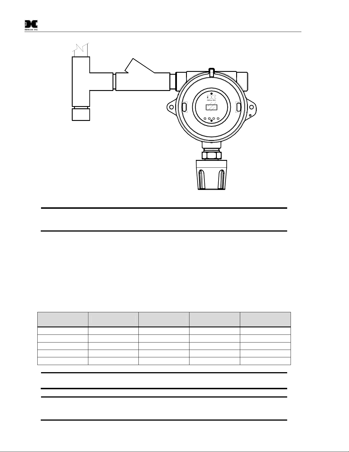
Figure 7 Typical Installation
Any unused ports should be blocked with suitable ¾” male NPT plugs. Detcon
supplies one ¾” NPT male plug with each J-box enclosure. If connections are other than ¾”
NPT, use an appropriate male plug of like construction material.
2.6 Field Wiring
Detcon Model TP-524D-HRT solid-state H2S sensor assemblies require three conductor connections between
power supplies and host electronic controller’s 4-20mA / HART Interface. Wiring designations are DC+, DC, MA (sensor signal). A 250 ohm load resistor is needed on the 4-20 mA line when it is not being used. The
maximum wire length between sensor and 24VDC source is shown in the Table below. The maximum wire
size for termination in the Junction Box is 14 AWG.
Table 2 Wire Gauge vs. Distance
AWG Wire Dia. Meters Feet
22 0.723mm 700 2080 3A
20 0.812mm 1120 3350 5A
18 1.024mm 1750 5250 7A
16 1.291mm 2800 8400 10A
14 1.628mm 4480 13,440 20A
Wiring table is based on stranded tinned copper wire and is designed to serve as a
reference only.
Shielded cable is required for installations where cable trays or conduit runs include
high voltage lines or other possible sources of induced interference. Separate conduit runs are
highly recommended in these cases.
Over-Current
Protection
TP-524D-HRT Instruction Manual Rev. 0.3 Page 8 of 48
Page 13
NOTE 3:
The supply of power should be from an isolated source with over-current protection
NOTE 4:
NOTE
NOTE
as stipulated in table.
A 250 ohm load resistor is needed on the 4-20 mA line when it is not being used.
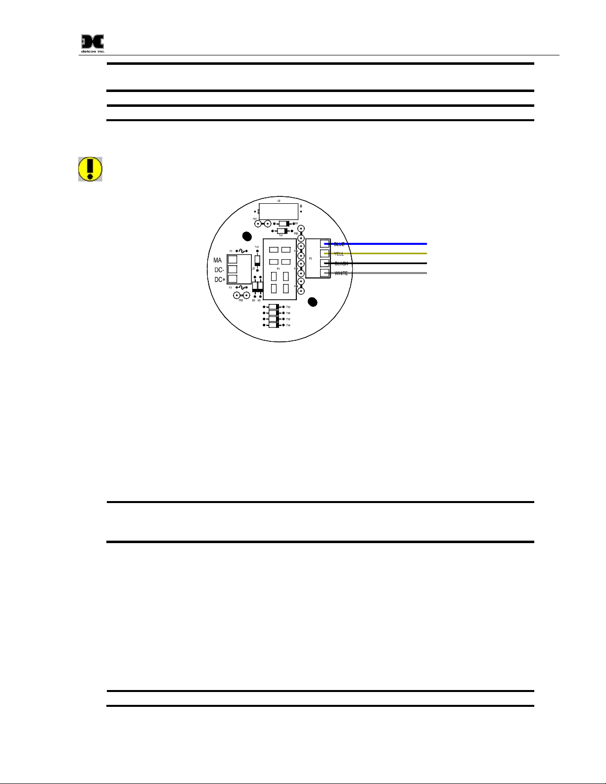
Terminal Connections
CAUTION: Do not apply System power to the sensor until all wiring is properly terminated. Refer
to Section 2.7 Initial Start Up
Customer
Wiring
Blue
Yellow
Black
White
Model TP-524D-HRT
Wiring to
H2S Sensor
Figure 8 Sensor Connector PCB
a) Remove the junction box cover and unplug the Transmitter Module. Identify the terminal blocks for
customer wire connections.
b) Observing correct polarity, terminate the 3-conductor 4-20mA field wiring (DC+, DC-, and MA) to the
sensor assembly wiring in accordance with the detail shown in Figure 8.
c) Trim all exposed wire leads if they are not permanently landed in the terminal block.
d) Plug the Transmitter Module into the connector PCB and replace the junction box cover.
: A 6-32 or 8-32 threaded exterior ground point is provided on most junction boxes for
an external ground. If the Sensor Assembly is not mechanically grounded, an external ground
strap must be used to ensure that the sensor is electrically grounded.
2.7 Initial Start Up
Upon completion of all mechanical mounting and termination of all field wiring, apply system power in the
range of 12-28VDC (24VDC typical) and observe the following normal conditions:
a) TP-524D-HRT display reads “0”, and no fault messages are flashing.
b) A temporary upscale reading may occur as the sensor heats up. This upscale reading will decrease to “0”
ppm within 1-2 minutes of power-up, assuming there is no gas in the area of the sensor.
: The 4-20mA signal is held constant at 4mA for the first two minutes after power up.
TP-524D-HRT Instruction Manual Rev. 0.3 Page 9 of 48
Page 14

Model TP-524D-HRT
NOTE:
NOTE
NOTE
c) Remove the desiccant cap about 10 minutes after applying power to the sensor and install the
weatherproof splashguard accessory supplied with the sensor.
A desiccant cap with a desiccant packet is attached to the sensor cell housing during
storage and shipping. This prevents water from contacting the sensor film, and as a result helps
to retain the stability of the factory span calibration.
: Store the desiccant caps with the desiccant packets in a sealed container (i.e. zip-lock
bag) for future use. It is advisable (but not mandatory) to reinstall the desiccant cap and packet
during prolonged periods without power (more than 2 days is considered “prolonged”). An
active desiccant packet is blue in color and turns pink when consumed. (P/N 960-399800-000
Package of 10)
Initial Operational Tests
After a warm up period of 1 hour, the sensor should be checked to verify sensitivity to H2S gas.
Material Requirements
-Detcon PN 600-610000-000 Splash Guard with integral Cal Port -OR-
-Detcon PN 943-000006-038 Threaded Calibration Adapter
-Detcon PN 942-010112-025 Span Gas; 25ppm H2S in balance Air at fixed flow rate between 200 - 500cc/min
(10ppm for 0-20ppm range)
-Detcon PN 985-241100-321 In-Line Humidifying Tube
: Do not use H2S in Nitrogen background gas mixtures. This will cause significant
reading inaccuracies.
a) Connect the In-Line Humidifying Tube between the cal gas cylinder and the sensor. The humidifying tube
will introduce the ambient relative humidity into the Cal Gas as it passes through the tube.
b) Attach the calibration adapter to the threaded sensor housing. Apply the test gas at a controlled flow rate
of 200 - 500cc/min (200cc/min is the recommended flow). Allow 1-2 minutes for the reading to stabilize.
Observe that during the 1-2 minutes the display increases to a level near that of the applied calibration gas
value.
c) Remove test gas and observe that the display decreases to “0”.
Initial operational tests are complete. Detcon H2S gas sensors are factory calibrated prior to shipment, and
should not require significant adjustment on start up. However, it is recommended that a complete calibration
test and adjustment be performed 16 to 24 hours after power-up. Refer to span calibration instructions in
Section 3.4.
TP-524D-HRT Instruction Manual Rev. 0.3 Page 10 of 48
Page 15

Model TP-524D-HRT
NOTE
3. Operation
3.1 Programming Magnet Operating Instructions
The Operator Interface of the Model 700 Series gas sensors is accomplished via two internal magnetic
switches located above and below the LED display (Figure 10). The two switches, labeled “PGM1” and
“PGM2”, allow for complete calibration and configuration, thereby eliminating the need for area declassification or the use of hot permits.
Figure 9 Magnetic Programming Tool
The magnetic programming tool (Figure 9) is used to operate the magnetic switches. Switch action is defined
as momentary contact, 3-second hold, and 10-second hold. (Hold times are defined as the time from the point
when the arrow prompt “” appears.) For momentary contact use, the programming magnet is briefly held
over a switch location. For 3-second hold, the programming magnet is held in place over the switch location
for three seconds. For 10-second hold, the programming magnet is held in place over the switch location for
10 seconds. The 3 and 10 second holds are generally used to enter calibration/program menus and save new
data. The momentary contact is generally used to move between menu items and to modify set-point values.
Arrows (“” and “”) are used on the LED display to indicate when the magnetic switches are activated. The
location of “PGM1” and “PGM2” are shown in Figure 10.
Program 1
PGM 1
HOUSTON,TEXAS
MicroSafe H2S Gas Sensor
TM
ALM ALM
FLT 1 2 CAL
PGM 2
Program 2
Figure 10 Magnetic Programming Switches
: While in the Program Mode, if there is no magnetic switch interaction after 4
consecutive menu scrolls, the sensor will automatically revert to normal operating condition.
While changing values inside menu items, if there is no magnet activity after 3-4 seconds
the sensor will revert to the menu scroll.
(Exception to this is with “Signal Output Check” mode.)
TP-524D-HRT Instruction Manual Rev. 0.3 Page 11 of 48
Page 16

Model TP-524D-HRT
3.2 Operator Interface
The operating interface is menu-driven via the two magnetic program switches located under the target marks
of the sensor housing. The two switches are referred to as “PGM1” and “PGM2”. The menu list consists of
three major items that include sub-menus as indicated below. (Refer to the complete Software Flow Chart.)
Normal Operation
Current Reading and Fault Status
Calibration Mode
AutoSpan
Program Mode
View Sensor Status
Sensor Model Type
Current Software Version
Range of Detection
AutoSpan Level
Days Since Last AutoSpan
Remaining Sensor Life
Sensor Heater Power
Sensor Heater Voltage
Raw Sensor Resistance
mA Output
Input Voltage Supply
Sensor Temperature
Alarm 1 Level
Alarm 1 Ascending
Alarm 1 Latching
Alarm 2 Level
Alarm 2 Ascending
Alarm 2 Latching
Fault Latching
Set AutoSpan Level
Set Range
Set Heater Power
Signal Output Check
Restore Default Settings
Alarm 1 Settings
Alarm 2 Settings
Fault Settings
TP-524D-HRT Instruction Manual Rev. 0.3 Page 12 of 48
Page 17
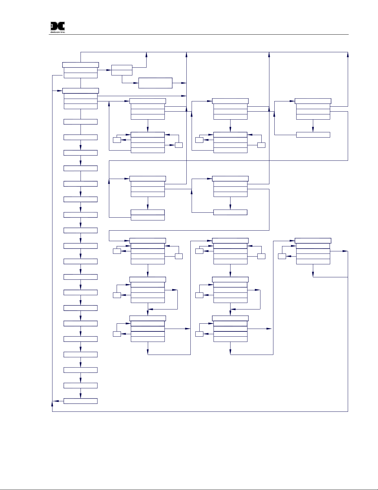
Software Flowchart
Model TP-524D-HRT
Normal Operation
PGM1 (3)
PGM2 (3)
View Sensor Status
Auto Time-Out
PGM1/2 (M)
PGM1/2 (3)
Model Type
Version X.XX
Range XXX ppm
AutoSpan @ XX
Last Cal XX Days
Sensor Life XXX%
Heater XXX mW
Heater X.XX VDC
Resistance XXXXX
mA Output XX.XX
PGM1 (3)
PGM2 (3)
inc
inc
Exit
Calibration Mode
(Auto Span)
Set AutoSpan Level
AutoTime-out
PGM1/2 (M)
PGM1/2 (3)
##
PGM2 (S)
PGM1 (S)
PGM1/2 (3)
Signal Output Check
Auto Time-Out
PGM2 (10)
Simulation
PGM1/2 (3)
Alarm 1 Level
##
Auto Time-Out
PGM1/2 (M)
PGM1/2 (3)
dec
dec
inc
inc
Set Range
Auto Time-Out
PGM1/2 (M)
PGM1/2 (3)
##
PGM2 (S)
PGM1 (S)
PGM1/2 (3)
Restore Defaults
Auto Time-Out
PGM1/2 (M)PGM1/2 (M)
PGM1/2 (10)
Defaults Restored
Alarm 1 Level
##
Auto Time-Out
PGM1/2 (M)
PGM1/2 (3)
dec
dec
inc
Set Heater Power
Auto Time-Out
PGM1/2 (M)
PGM1/2 (3)
Setting Heater
Dault Latching
Y/N
Auto Time Out
PGM1/2 (M)
PGM1/2 (3)
Voltage XX.X VDC
Sensor Temp XX C
Alarm 1 Level
Alarm 1 Ascending
Alarm 1 Latching
Alarm 2 Level
Alarm 2 Ascending
Alarm 2 Latching
Fault Latching
Alarm 1 Ascending
Y/N
Auto Time Out
inc
inc
PGM1/2 (M)
PGM1/2 (3)
Alarm 1 Latching
Y/N
Auto Time Out
PGM1/2 (M)
PGM1/2 (3)
LEGEND:
PGM1 - Program Switch Location #1
PGM2 - Program Switch Location #2
inc - Increase
dec - Decrease
#, ##, ### - numeric values
Figure 11 TP-524D-HRT Software Flowchart
inc
inc
Alarm 1 Ascending
Y/N
Auto Time Out
PGM1/2 (M)
PGM1/2 (3)
Alarm 1 Latching
Y/N
Auto Time Out
PGM1/2 (M)
PGM1/2 (3)
(S) - Momentary Swipe.
(M) - Momentary hold of Magnet during text
scroll until the ">" appears, then release.
(3) - 3 second hold from ">" prompt.
(10) - 10 second hold from ">" prompt.
Auto Time-out - 5 seconds.
TP-524D-HRT Instruction Manual Rev. 0.3 Page 13 of 48
Page 18

Model TP-524D-HRT
NOTE 1:
NOTE 2:
NOTE 3:
NOTE 4
3.3 Normal Operation
In normal operation, the display continuously shows the current sensor reading, which will normally appear as
“0”. Once every minute, the LED display will flash the sensor’s units of measure and the gas type (i.e. ppm
H2S). If the sensor is actively experiencing any diagnostic faults, a “Fault Detected” message will scroll across
the display on the display once every minute instead of the units of measure and the gas type. At any time,
while the sensor is in “Fault Detected” mode, PGM1 or PGM2 can be swiped to prompt the sensor to display a
list of the active faults.
In normal operation, the 4-20mA current output linearity corresponds with the full-scale range.
3.4 Calibration Mode (AutoSpan)
Calibration Mode allows for sensor span calibration. Span calibration should be performed on a routine basis
(quarterly minimum) to ensure reliable performance. If a sensor has been exposed to any de-sensitizing gases
or to very high over-range H2S levels, then a re-calibration should be considered. Unless otherwise specified,
span adjustment is recommended at 25ppm for the 0-100 and 0-50ppm ranges (and 10ppm for 0-20ppm
range). This function is called “AUTO SPAN.”
Material Requirements:
-Detcon PN 327-000000-000 MicroSafe™ Programming Magnet
-Detcon PN 600-610000-000 Splash Guard with integral Cal Port -OR-
-Detcon PN 943-000006-038 Threaded Calibration Adapter
-Detcon PN 985-241100-321 In-Line Humidifying Tube
-Detcon PN 942-010112-025 H2S Span Gas (recommended) or other suitable span gas source containing H2S
gas in air balance. A fixed flow rate of 200-500cc/min is recommended.
Before performing AutoSpan Calibration, verify that the AutoSpan level matches
the span calibration gas concentration as described in Section 3.5.2 Set AutoSpan Level.
The span gas source must have a normal background concentration of 20.9% O2
(H2S balanced with Air). Pure Nitrogen background mixtures are not acceptable! Significant
span calibration inaccuracies will result.
An H2S gas concentration of 25ppm is strongly recommended for 0-50 and 0100ppm ranges (10ppm span gas for 0-20ppm range). This should be supplied at a controlled
flow rate of 200 to 500cc/min, with 200cc/min being the recommended flow rate. Other
concentrations can be used if as they fall within allowable levels.
: Span gas bottles contain 0% humidity and this ultra-low humidity condition will
cause inaccurate readings when used to calibrate a sensor. To prevent this error, Detcon
prescribes the use of a 24” flexible In-Line Humidifying Tube, which adds the relative
humidity to the span gas. The humidifying tube is not necessary when using a gas generating
calibration device that consists of pumped ambient air and an H2S generating source.
CAUTION: Verification that the calibration gas level setting matches the calibration span gas
concentration is required before executing “AutoSpan” calibration. These two numbers must be equal.
AutoSpan consists of entering Calibration Mode and following the menu-displayed instructions. The display
will ask for the application of span gas in a specific concentration. The applied gas concentration must be
equal to the calibration gas level setting. The factory default setting and recommendation for span gas
TP-524D-HRT Instruction Manual Rev. 0.3 Page 14 of 48
Page 19

Model TP-524D-HRT
NOTE:
NOTE 1
“Range Fault”
concentration is 10ppm for the 0-20ppm range and 25ppm for the 0-50ppm and 0-100ppm ranges. If a span
gas containing the recommended concentration is not available, other concentrations may be used as long as
they fall between 10% and 50% of selected full-scale range. However, any alternate span gas concentration
value must be programmed into the sensor via the “Set AutoSpan Level” menu before proceeding with
AutoSpan calibration. Follow the instructions “a” through “e” below for AutoSpan calibration.
a) Verify that the AutoSpan Level is equal to the Calibration Span Gas Concentration. (Refer to View
Sensor Status in Section 3.5.1.) If the AutoSpan Level is not equal to the Calibration span gas
concentration, adjust the AutoSpan Level as instructed in Section 3.5.2 Set AutoSpan Level.
b) From Normal Operation, enter Calibration Mode by holding the programming magnet over PGM1 for 3
seconds. Note, the “” prompt will show that the magnetic switch is activated during the 3 second hold
period. The display will then scroll “PGM1=Exit PGM2=Span”. Hold the programming magnet over
PGM2 for 3 seconds to execute AutoSpan (or allow to timeout in 5 seconds if AutoSpan is not intended).
The display will then scroll “Apply XX ppm Gas”.
Upon entering Calibration Mode, the 4-20mA signal drops to 2mA and is held at this
level until the program returns to normal operation.
c) Apply the span calibration test gas via the In-Line Humidifying Tube at a flow rate of 200-500cc/min
(200cc/min is the recommended flow rate). As the sensor signal begins to increase the display will switch
to reporting “XX” reading as the display shows the sensor’s “as found” response to the span gas presented.
If it fails to meet the minimum in-range signal change criteria within 2½ minutes, the display will report
“Range Fault” twice and the sensor will return to normal operation, aborting the AutoSpan sequence. The
sensor will continue to report a “Range Fault” and will not clear the fault until a successful AutoSpan is
completed.
Assuming acceptable sensor signal change, after 3 minutes the reading will auto-adjust to the programmed
AutoSpan level. During the next 30 seconds, the AutoSpan sequence checks the sensor for acceptable reading
stability. If the sensor fails the stability check, the reading is re-adjusted back to the AutoSpan level and the
cycle repeats until the stability check is passed. Up to three additional, 30-second stability check periods are
allowed before the sensor reports a “Stability Fault” and returns to normal operation, aborting the AutoSpan
sequence. The sensor will continue to report a “Stability Fault” and will not clear the fault until a successful
AutoSpan is completed.
If the sensor passes the stability check, the sensor reports a series of messages:
“AutoSpan Complete”
“Sensor Life XXX%”
“Remove Span Gas”
d) Remove the span gas and calibration adapter. The display will report a live reading as the sensor clears
toward “0”. When the reading clears below 8ppm, the sensor will display “Span Complete” and will
revert to normal operation. If the sensor fails to clear to less than 8ppm within 5 minutes, a “Clearing
Fault” will be reported and the sensor will return to normal operation, aborting the AutoSpan sequence.
The sensor will continue to report a “Clearing Fault” and will not clear the fault until a successful
AutoSpan is completed.
e) AutoSpan calibration is complete.
: If the sensor fails the minimum signal change criteria, a
will be
declared and a “Fault Detected” message will be displayed alternately with the sensor’s current
reading. The 4-20mA output will be taken to 0mA.
TP-524D-HRT Instruction Manual Rev. 0.3 Page 15 of 48
Page 20

Model TP-524D-HRT
NOTE 2
“Stability Fault”
NOTE 3
Clearing Fault
NO
TE 4
Range Fault
Stability Fault
: If the sensor fails the stability criteria, a
will be declared and a
“Fault Detected” message will be displayed alternately with the sensor’s current reading. The
4-20mA output will be taken to 0mA.
: If the sensor fails the clearing time criteria, a “
” will be declared and a
“Fault Detected” message will be displayed alternately with the sensor’s current reading. The
4-20mA output will be taken to 0mA.
: The most common cause of “
” and “
” is the improper
storage of the unit / sensor cell. When the sensor power is removed for any period of time, the
sensor cell should be protected with a Desiccant Pack (P/N 960-240010-000) and covered by
the Dust Cap (P/N 600-003232-000)
3.5 Program Mode
Program Mode provides a “View Sensor Status” menu to check operational and configuration parameters.
Program Mode provides for adjustment of the AutoSpan Level, Sensor Range, and Heater Power.
Additionally, Program Mode includes the diagnostic functions “Signal Output Check” and “Restore Factory
Defaults”.
The Program Mode menu items appear in the order presented below:
View Sensor Status
Set AutoSpan Level
Set Range
Set Heater Power
Signal Output Check
Restore Default Settings
Alarm 1 Settings
Alarm 2 Settings
Fault Settings
Navigating Program Mode
From Normal Operation, enter Program Mode by holding the magnet over PGM2 for 4 seconds (until the
displays starts to scroll “View Sensor Status”). Note, the “” prompt will show that the magnetic switch is
activated during the 4 second hold period. The sensor will enter Program Mode and the display will display
the first menu item “View Sensor Status”. To advance to the next menu item, hold the magnet over PGM1 or
PGM2 while the current menu item’s text is scrolling. At the conclusion of the text scroll the arrow prompt
(“” for PGM2 or “” for PGM1) will appear, immediately remove the magnet. The display will advance to
the next menu item. Repeat this process until the desired menu item is displayed. Note, PGM1 moves the
menu items from right to left and PGM2 moves the menu items from left to right.
To enter a menu item, hold the magnet over PGM1 or PGM2 while the menu item is scrolling. At the
conclusion of the text scroll the “”prompt (“” for PGM2 or “” for PGM1) will appear, continue to hold the
magnet over PGM1 or PGM2 for an additional 3-4 seconds to enter the selected menu item. If there is no
magnet activity while the menu item text is scrolling (typically 4 repeated text scrolls), the sensor will
automatically revert to Normal Operation.
3.5.1 View Sensor Status
TP-524D-HRT Instruction Manual Rev. 0.3 Page 16 of 48
Page 21

Model TP-524D-HRT
View Sensor Status displays all current configuration and operational parameters including: sensor type,
software version number, detection range, AutoSpan level, days since last AutoSpan, estimated remaining
sensor life, heater power, heater voltage, raw resistance, mA output, input voltage, and sensor ambient
temperature.
From the View Sensor Status text scroll, hold the magnet over PGM1 or PGM2 until the “” prompt appears
and continue to hold the magnet in place for an additional 3-4 seconds (until the display starts to scroll “Status
Is”). The display will scroll the complete list of sensor status parameters sequentially:
Sensor Model Type
The menu item appears as: “TP-524D”
Current Software Version
The menu item appears as: “V X.XXZ”
Range of Detection.
The menu item appears as: “Range XXXppm”
AutoSpan Level.
The menu item appears as: “Auto Span Level XXppm”
Days Since Last AutoSpan.
The menu items appears as: “Last Cal XX days”
Remaining Sensor Life.
The menu item appears as: “Sensor Life 100%”
Sensor Heater Power.
The menu item appears as: “Heater XXXmW”
Sensor Heater Voltage
The menu item appears as: “Heater X.XXVDC
Raw Sensor Resistance
The menu item appears as: “Resistance XXXXX”
mA Output
The menu item appears as: “mA Output XX.XX mA”
Input Voltage Supply
The menu item appears as: “Voltage XX.X VDC”
Operating Temperature
The menu item appears as: “Temp XX C”
TP-524D-HRT Instruction Manual Rev. 0.3 Page 17 of 48
Page 22

Alarm 1 Level
The menu item appears as: “Alarm 1 Level XX”
Alarm 1 Ascending
The menu item appears as: “Alarm 1 Ascending or Descending”
Alarm 1 Latching
The menu item appears as: “Alarm 1 Latching or Non-Latching”
Alarm 2 Level
The menu item appears as: “Alarm 2 Level XX”
Alarm 2 Ascending
The menu item appears as: “Alarm 2 Ascending or Descending”
Alarm 2 Latching
The menu item appears as: “Alarm 2 Latching or Non-Latching”
Model TP-524D-HRT
Fault Latching
The menu item appears as: “Fault Latching or Non-Latching”
When the status list sequence is complete, the display will revert to the “View Sensor Status” text scroll. The
user can either: 1) review list again by executing another 3-4 second hold, 2) move to another menu item by
executing a momentary hold over PGM1 or PGM2, or 3) return to Normal Operation via automatic timeout of
about 15 seconds (the display will scroll “View Sensor Status” 4 times and then return to Normal Operation).
3.5.2 Set AutoSpan Level
Set AutoSpan Level is used to set the span gas concentration level that is being used to calibrate the sensor.
This level is adjustable from 10% to 50% of selected full-scale range. The current setting can be viewed in
View Program Status.
The menu item appears as: “Set AutoSpan Level”.
From the Set AutoSpan Level text scroll, hold the magnet over PGM1 or PGM2 until the “” prompt appears
and continue to hold the magnet in place for an additional 3-4 seconds (until the display starts to scroll “Set
Level”). The display will switch to “XX“(where XX is the current gas level). Swipe the magnet momentarily
over PGM2 to increase or PGM1 to decrease the AutoSpan Level until the correct level is displayed. When
the correct level is achieved, hold the magnet over PGM1 or PGM2 for 3-4 seconds to accept the new value.
The display will scroll “Level Saved”, and revert to “Set AutoSpan Level” text scroll.
Move to another menu item by executing a momentary hold, or return to Normal Operation via automatic
timeout of about 15 seconds (the display will scroll “Set AutoSpan Level” 4 times and then return to Normal
Operation).
3.5.3 Set Range
TP-524D-HRT Instruction Manual Rev. 0.3 Page 18 of 48
Page 23

Model TP-524D-HRT
NOTE
N
OTE
NOTE
Set Range is used to change full-scale ranges. This is selectable between 0-20, 0-50, and 0-100ppm. The
current range can be viewed in View Sensor Status using instruction given in Section 3.5.1 View Sensor
Status.
The menu item appears as: “Set Range”.
From the “Set Range” text scroll, hold the programming magnet over PGM1 or PGM2 until the “” prompt
appears and continue to hold the magnet in place for an additional 3-4 seconds (until the display starts to scroll
“Set Range”). The display will then switch to “XXX“(where XXX is the current Range). Swipe the magnet
momentarily over PGM2 to increase or PGM1 to decrease the range Level until the desired range is displayed.
Hold the magnet over PGM1 or PGM2 for 3 seconds to accept the new value. The display will scroll “Range
Saved”, and revert to “Set Range” text scroll.
Move to another menu item by executing a momentary hold, or, return to Normal Operation via automatic
timeout of about 15 seconds (the display will scroll “Set Range” 7 times and then return to Normal Operation).
: When switching between ranges, it may be necessary to readjust the AutoSpan Level.
3.5.4 Set Heater Power
Set Heater Power is used to set the each H2S sensor to the optimum operating temperature. This function is
performed during factory calibration of each TP-524D-HRT sensor assembly, and is not necessary during
installation. However, it is necessary to perform in the field if the plug-in H2S sensor is replaced, mounted
remotely from the Transmitter Module, or if the Restore Factory Defaults function has been executed.
The menu item appears as: “Set Heater Power”.
: “Set Heater Power” is only necessary after new plug-in H2S sensor installation,
mounted remotely from the Transmitter Module, or after use of the “Restore Factory Defaults”
function. A full 3-4 second magnet hold on PGM1 or PGM 2 is required to execute this
function.
From the “Set Heater Power” text scroll, hold the programming magnet over PGM1 or PGM2 until the “”
prompt appears and continue to hold the magnet in place for an additional 3-4 seconds (until the display starts
to scroll “Setting Heater”). After scrolling “Setting Heater”, the sensor will adjust the Heater power. The
sequence should require about 2-minutes. When the cycle is complete, the display will revert to the “Set
Heater Power” text scroll.
: If the sensor cannot adjust the heater power within 3 minutes an error message, “Can’t
set, Reverting to Default”, will be scrolled. Refer to section 6 Troubleshooting Guide.
Move to another menu item by executing a momentary hold, or, return to Normal Operation via automatic
timeout of about 15 seconds (the display will scroll “Set Heater Power” 4 times and then return to Normal
Operation).
The current values for heater power and heater voltage can be observed in the “View Sensor Status” menu.
The target heater power setting at 25C operating temperature is 240 ± 5mW. At the operating temperature
extremes the observed heater power settings will vary according to the data below:
50C normal heater power range is 210 ± 5mW
0C normal heater power range is 260 ± 5mW
-20C normal heater power range is 275 ± 5mW
-40C normal heater power range is 290 ± 5mW
TP-524D-HRT Instruction Manual Rev. 0.3 Page 19 of 48
Page 24

Model TP-524D-HRT
NOTE
NOTE
NOTE
3.5.5 Signal Output Check
Signal Output Check provides a simulated 4-20mA output. This simulation allows the user to conveniently
perform a functional system check of their entire safety system. This signal output simulation also aids the
user in performing troubleshooting of signal wiring problems.
The menu item appears as: “Signal Output Check”.
From the “Signal Output Check” text scroll, hold the magnet over PGM1 or PGM2 until the “” prompt
appears and then hold continuously for an additional 10 seconds. Once initiated, the display will scroll
“Simulation Active” until the function is stopped. During simulation mode, the 4-20mA value will be
increased from 4.0mA to 20.0mA (in 1% of range increments at about a 1 second update rate) and then
decreased from 20.0mA to 4.0mA.
: Signal Output Check stays active indefinitely until the user stops the function. There
is no automatic timeout for this feature.
To end simulation mode, hold magnet over PGM1 or PGM2 for 3 seconds. The display will either move to the
prior menu item or move to the next menu item respectively.
Move to another menu item by executing a momentary hold, or, return to Normal Operation via automatic
timeout of about 15 seconds.
3.5.6 Restore Factory Defaults
Restore Factory Defaults is used to clear current user configuration and calibration data from memory and
revert to factory default values. This may be required if the settings have been configured improperly and a
known reference point needs to be re-established to correct the problem.
This menu item appears as: “Restore Defaults”.
: “Restoring Factory Defaults” should only be used when absolutely necessary. All
previously existing configuration inputs will have to be re-entered if this function is executed.
A full 10-second magnet hold on PGM 1 is required to execute this function.
From the “Restore Defaults” text scroll, hold the programming magnet over PGM1 until the “” prompt
appears and continue to hold 10 seconds. The display will scroll “Restoring Defaults”, and then will revert to
the “Restore Defaults” text scroll.
Move to another menu item by executing a momentary hold, or, return to Normal Operation via automatic
timeout of about 15 seconds (the display will scroll “Restore Defaults” 4 times and then return to Normal
Operation).
Following the execution of “Restore Defaults”, the TP-524D-HRT will revert to its factory default settings.
The default settings are:
: The following must be performed in order before the sensor can be placed back into
operation.
Range = 100ppm. Range must be set appropriately by the operator (3.5.3).
AutoSpan Level = 25ppm. AutoSpan level must be set appropriately by the operator (3.5.2).
TP-524D-HRT Instruction Manual Rev. 0.3 Page 20 of 48
Page 25

Model TP-524D-HRT
Heater Power: Heater Power settings are lost and “Set Heater Power” (3.5.4) must be performed before
“AutoSpan”.
AutoSpan: AutoSpan Settings are lost and a successful “AutoSpan” must be performed before placing the
Sensor into operation (3.4).
3.5.7 Alarm 1 and 2 Settings
The TP-524D has the ability to set alarm levels that are displayed on the front of the sensor via the LED’s
ALM 1 and ALM 2. These alarm LEDs can be set as latching or non-latching. In non-latching mode, the
LED is deactivated as soon as the sensor alarm condition is cleared. In latching mode, the LED remains active
even after the alarm condition has cleared. Once activated, the LED can only be deactivated by swiping a
magnetic programming tool above the PGM1 or PGM2 mark on the TP-524D face plate.
The alarm LEDs can be configured for ascending or descending mode. In ascending mode the LED will be
activated when the concentration is above the alarm threshold. This is the most common mode of operation
for the TP-524D. The alarm LEDs can also be activated in descending mode. In this mode, the alarm LEDs
will activate when the concentration is below the alarm threshold.
The menu item appears as: “Alarm X Settings”
From the “Alarm X Settings” text scroll, hold the programming magnet over PGM1 or PGM2 until the “▼”
prompt appears and continue to hold the magnet in place for an additional 3-4 seconds (until the display starts
to scroll “Set Level”). The display will then switch to “XXX“(where XXX is the current alarm level in ppm).
Swipe the magnet momentarily over PGM2 to decrease or PGM1 to increase the alarm level until the desired
level is displayed. Hold the magnet over PGM1 or PGM2 for 3 seconds to accept the new value (until the
display starts to scroll “Level Saved”).
The display will scroll “Set Ascending”, and then switch to “Yes” or “No”. “Yes” indicates the LED is in
ascending mode and “No” indicates the LED is in descending mode. Swipe the magnet momentarily over
PGM2 or PGM1 until the correct value is displayed. Hold the magnet over PGM1 or PGM2 for 3 seconds to
accept the new value.
The display will scroll “Set Latching”, and then switch to “Yes” or “No”. “No” indicates the LED is nonlatching and “Yes” indicates the LED is latching. Swipe the magnet momentarily over PGM2 or PGM1 until
the correct value is displayed. Hold the magnet over PGM1 or PGM2 for 3 seconds to accept the new value.
Hold the magnet over PGM1 or PGM2 for 3 seconds to accept the new value (until the display starts to scroll
“Saved”). Move to another menu item by executing a momentary hold, or, return to Normal Operation via
automatic timeout of about 15 seconds (the display will scroll “Alarm X Settings” 4 times and then return to
Normal Operation).
3.5.8 Fault Settings
The TP-524D Fault LED can be configured to change state when the sensor experiences a fault condition. This
LED can be configured as either latching or non-latching. In non-latching mode, the LED is deactivated as
soon as the fault condition is cleared. In latching mode, the LED remains active even after the fault condition
has cleared. Once activated, the LED can only be deactivated by swiping a magnetic programming tool above
the PGM1 or PGM2 mark on the TP-524D face plate.
The menu item appears as: “Fault Settings”
From the “Fault Settings” text scroll, hold the programming magnet over PGM1 or PGM2 until the “▼”
prompt appears and continue to hold the magnet in place for an additional 3-4 seconds. The display will scroll
“Set Latching”, and then switch to “Yes” or “No”. “No” indicates the relay is non-latching and “Yes”
TP-524D-HRT Instruction Manual Rev. 0.3 Page 21 of 48
Page 26

Model TP-524D-HRT
NOTE
indicates the relay is latching. Swipe the magnet momentarily over PGM2 or PGM1 until the correct value is
displayed. Hold the magnet over PGM1 or PGM2 for 3 seconds to accept the new value.
Hold the magnet over PGM1 or PGM2 for 3 seconds to accept the new value (until the display starts to scroll
“Saved”). Move to another menu item by executing a momentary hold, or, return to Normal Operation via
automatic timeout of about 15 seconds (the display will scroll “Fault Settings” 4 times and then return to
Normal Operation).
3.6 Program Features
Detcon TP-524D-HRT H2S gas sensors incorporate a comprehensive set of diagnostic features to achieve FailSafe Operation. These Operational features and Failsafe Diagnostic features are detailed below.
3.6.1 Operational Features
Over-Range
When gas greater than the full-scale range is detected, the sensor display will continuously flash the full-scale
reading (20, 50, 100ppm). This designates an over-range condition. The 4-20mA signal will report a 22mA
output during this time.
In-Calibration Status
When the sensor is engaged in AutoSpan calibration, the 4-20mA output signal is taken to 2.0mA. This alerts
the user that the sensor is not in an active measurement mode. This feature also allows the user to log the
AutoSpan events via their master control system.
Sensor Life
Sensor Life is calculated after each AutoSpan calibration and is reported as an indicator of remaining service
life. It is reported in the “View Sensor Status” menu. Sensor Life is reported on a scale of 0-100%. When
Sensor Life falls below 25%, the sensor cell should be replaced within a reasonable maintenance schedule.
Last AutoSpan Date
This reports the number of days that have elapsed since the last successful AutoSpan. This is reported in the
View Sensor Status menu. After 180 days, an AutoSpan Fault will be declared.
3.6.2 Fault Diagnostic/Failsafe Features
Fail-Safe/Fault Supervision
Model TP-524D-HRT MicroSafe™ sensors are designed for Fail-Safe operation. If any of the diagnostic
faults listed below are active, the sensor display will scroll the message “Fault Detected” every 60 seconds
during normal operation. At any time during “Fault Detected” mode, holding the programming magnet over
PGM1 or PGM2 for 1 second will display the active fault(s). All active faults are reported sequentially.
Most fault conditions result in failed operation of the sensor. In these cases the 4-20mA signal is dropped to
the universal fault level of 0mA. These include the AutoSpan Calibration faults, Heater Fault, Sensor Fault,
Processor Fault, Memory Fault, Loop Fault, and Input Voltage Fault. (The 0mA fault level is not employed
for a Temperature Fault, or during Calibration.)
: Refer to the Troubleshooting Guide, Section 6, for guidance on fault conditions.
TP-524D-HRT Instruction Manual Rev. 0.3 Page 22 of 48
Page 27

Model TP-524D-HRT
Range Fault – AutoSpan
If the sensor fails the minimum signal change criteria during AutoSpan sequence (Section 3.4), the “Range
Fault” will be declared. A “Range Fault” will cause a “Fault Detected” message to scroll once a minute on the
sensor display and drop the 4-20mA output to 0mA. The sensor should be considered “Out-of-Service” until a
successful AutoSpan calibration is performed.
Stability Fault - AutoSpan
If the sensor fails the signal stability criteria during AutoSpan sequence (Section 3.4), the “Stability Fault” will
be declared. A “Stability Fault” will cause a “Fault Detected” message to scroll once a minute on the sensor
display and drop the mA output to 0mA. The sensor should be considered as “Out-of-Service” until a
successful AutoSpan calibration is performed.
Clearing Fault - AutoSpan
If the sensor fails the signal stability criteria during AutoSpan sequence (Section 3.4), the “Clearing Fault” will
be declared. A “Clearing Fault” will cause a “Fault Detected” message to scroll once a minute on the sensor
display and drop the mA output to 0mA. The sensor should be considered as “Out-of-Service” until a
successful AutoSpan calibration is performed.
Open Heater Fault
If the sensor heater should fail and become electrically open, a “Heater Fault” will be declared. A “Heater
Fault” will cause a “Fault Detected” message to scroll once a minute on the sensor display. If a Heater Fault
occurs, the 4-20mA signal will be set at 0mA until the fault condition is resolved.
Open Sensor Fault
If the sensor film should fail and become electrically open, a “Sensor Fault” is declared. A “Sensor Fault” will
cause a “Fault Detected” message to scroll once a minute on the sensor display. If a Sensor Fault occurs, the
4-20mA signal will be set at 0mA until the fault condition is resolved.
Processor Fault
If the detector has any unrecoverable run-time errors, a “Processor Fault” is declared. A “Processor Fault”
will cause a “Fault Detected” message to scroll once a minute on the sensor display. If a Processor Fault
occurs, the 4-20mA signal will be set at 0mA until the fault condition is resolved.
Memory Fault
If the detector has a failure in saving new data to memory, a “Memory Fault” is declared. A “Memory Fault”
will cause the “Fault Detected” message to scroll once a minute on the sensor display. If a Memory Fault
occurs, the 4-20mA signal will be set at 0mA until the fault condition is resolved.
4-20mA Loop Fault
If the sensor detects a condition where the 4-20mA output loop is not functional (high loop resistance or failed
circuit function) a “4-20mA Fault” is declared. A “4-20mA Fault” will cause the “Fault Detected” message to
scroll once a minute on the ITM display. If a Loop Fault occurs, the 4-20mA signal will be set at 0mA until
the fault condition is resolved. If the 4-20mA current loop is still out of tolerance, contact Detcon at
Service@detcon.com, or contact Detcon customer service.
TP-524D-HRT Instruction Manual Rev. 0.3 Page 23 of 48
Page 28

Model TP-524D-HRT
Input Voltage Fault
If the detector is currently receiving an input voltage that is outside of the 11.5-28VDC range, an “Input
Voltage Fault” is declared. An “Input Voltage Fault” will cause the “Fault Detected” message to scroll once a
minute on the sensor display. If an Input Voltage Fault occurs, the 4-20mA signal will be set at 0mA until the
fault condition is resolved.
Temperature Fault
If the detector is reporting currently an ambient temperature that is outside of the –40ºC to +75ºC range, a
“Temperature Fault” is declared. A “Temperature Fault” will cause the “Fault Detected” message to scroll
once a minute on the sensor display. If a Temperature Fault occurs, the 4-20mA signal remains operational.
AutoSpan Fault
If 180 days has elapsed since the last successful AutoSpan, an AutoSpan Fault will be generated. An
“AutoSpan Fault” will cause the “Fault Detected” message to scroll once a minute on the sensor display. If an
AutoSpan Reminder Fault occurs, the 4-20mA signal remains operational.
TP-524D-HRT Instruction Manual Rev. 0.3 Page 24 of 48
Page 29

Model TP-524D-HRT
4. HRT Bridge
The HRT Bridge interface is an integral part of the Transmitter Module for the TP-524D-HRT. The sensor
utilizes the 4-20mA output with the added HART interface information.
4.1 Description
The HRT Bridge PCA is a bi-directional digital communication interface that provides data communication
between the Model TP-524D-HRT sensor and HART®-enabled devices. The HART®(Highway Addressable
Remote Transducer) Communication Protocol is a standard for sending and receiving digital information
across analog wires between smart devices and a control host or monitoring system. A host can be any
software application from a technician's hand-held device or laptop to a plant's process control, asset
management, safety or other system using any control platform.
The HART Communication Protocol makes use of the Bell 202 Frequency Shift Keying (FSK) Standard to
superimpose digital communication signals on the 4-20mA signal utilized by the TP-524D-HRT sensor. This
enables two-way communication and makes it possible for additional information to be transferred to and from
the sensor. This communication includes the ability for the Host to:
Configure or re-configure the sensor
Perform sensor diagnostics
Troubleshoot the sensor
Read additional information from the sensor
Determine the sensor’s health and status
4.2 Connecting the HRT Bridge
The HRT Bridge connection to the Host utilizes a 3-wire connection of power, power return, and mA output
(Refer to Figure 5 Base Connector Board). Connect the 24VDC to the base connector board terminal labeled
‘DC+’. Connect the 24V Return to the terminal labeled ‘DC-’, and connect the 4-20mA to the terminal
labeled ‘mA’. The 4-20mA signal from the HRT Bridge must be connected to a load resistor to operate
properly. If this signal is not terminated properly, the HRT Bridge, and the HART Interface will fail to work
properly.
4.3 Operation
When power is applied to the TP-524D with HRT Bridge, the HRT Bridge will go through a boot up sequence
that will last for approximately 30 seconds. During this time, the 4-20mA line will be held at 1mA. After the
boot up sequence the HRT Bridge will enter normal operation, and communication with the Host will begin.
A red LED (D7) Labeled “HART” on the HRT Bridge PCA will illuminate when the PCA is communicating
with the HART Host. (The HRT Bridge is part of the TP-524D-HRT Transmitter assembly.)
The 4-20mA signal from the HRT Bridge must be connected to a load resistor for HART communication to
operate properly. If this signal is not terminated properly, the HRT Bridge, and the HART Interface will fail to
work. Normal termination for the 4-20mA signal is accomplished by connection to a Host device, which will
have the correct load to terminate the signal properly.
If the HRT Bridge senses a fault in the sensor, it will take the 4-20mA signal down to 1mA. This 1mA signal
will signify to the Host that a sensor fault has occurred, and the Host should, in turn, flag an error with the
associated sensor.
TP-524D-HRT Instruction Manual Rev. 0.3 Page 25 of 48
Page 30

Model TP-524D-HRT
NOTE
The screen shots shown below are taken from the HART
Communication
The HRT Bridge communicates with the TP-524D-HRT sensor through Modbus™. The HRT Bridge reads
the appropriate Modbus™ register and creates the 4-20mA signal from the register reading. This allows the
HRT Bridge complete control of the HART Communications. A red LED Labeled “MODBUS” will blink
when communication with the sensor occurs.
The HART interface has the ability to take the sensor into calibration. If the sensor is taken into calibration
via the HART interface, the HART Communication Protocol will inform the Host that the sensor is in
calibration mode, and will not set a fault. The 4-20mA signal will be set at 2mA. Starting a calibration using
the sensor interface and magnetic tool will also cause the 4-20mA to be set to 2mA.
4.4 Operator Interface
The HRT Bridge provides the ability to interface with the sensor via the HART Interface. The HART
interface Host can be a PC, a Laptop, or several handheld devices such as the Emerson 375 Field
Communicator. Although the displays on each device may be different and the menu names may change, the
information provided should be the same. The HART Interface consists of three basic Menus, each with a
subset of menus or screens:
Device Variables Menu
Primary Variables
Identification
Diagnostics Menu
Device Status
Sensor Status
Device Status Menu
Configuration Setup
Calibration
HART Setup
:
Foundation SDC625 Reference Host. The user’s screen appearance may be different
depending on the HART host used.
4.4.1 Device Menu
4.4.1.1 Primary Variables
The primary Variable Screen contains the basic information from the sensor and is broken into four basic
sections. None of these variables are changeable, and are directly read from the sensor.
TP-524D-HRT Instruction Manual Rev. 0.3 Page 26 of 48
Page 31

Figure 12 Primary Variables
Model TP-524D-HRT
Primary Variables
Concentration – the value of the gas concentration measured by the sensor. The units of measurement
(ppm, ppb, or %) are shown to the right of the concentration value. This is the HART primary
variable.
Loop Current – the value of the output 4-20mA loop current
PV %rnge – Primary variable percent of range
EngUnits – the measurement units and gas type
Range Variables
PV LRV – Primary variable lower range value (normally 0 for most sensors)
PV URV – Primary variable upper range value, or the range of the sensor (i.e. 100ppm, 10ppm, 5%,
etc.)
Device Status
Indicates the device has more status information available. If this icon is green, no additional status
information is available. If it is red, refer to Section 4.4.2 Diagnostics for more information.
Measured Values
Concentration – the value of the gas concentration measured by the sensor. The units of measurement
(ppm, ppb, or %) are shown to the right of the concentration value
Temperature – displayed in degrees Centigrade.
PS Voltage – power supply voltage. Nominally 24VDC
PV – Graphic display
A graphic display of the sensor concentration reading may also be displayed in this screen. The graph will be
a graphic display of concentration verses time.
TP-524D-HRT Instruction Manual Rev. 0.3 Page 27 of 48
Page 32
Model TP-524D-HRT
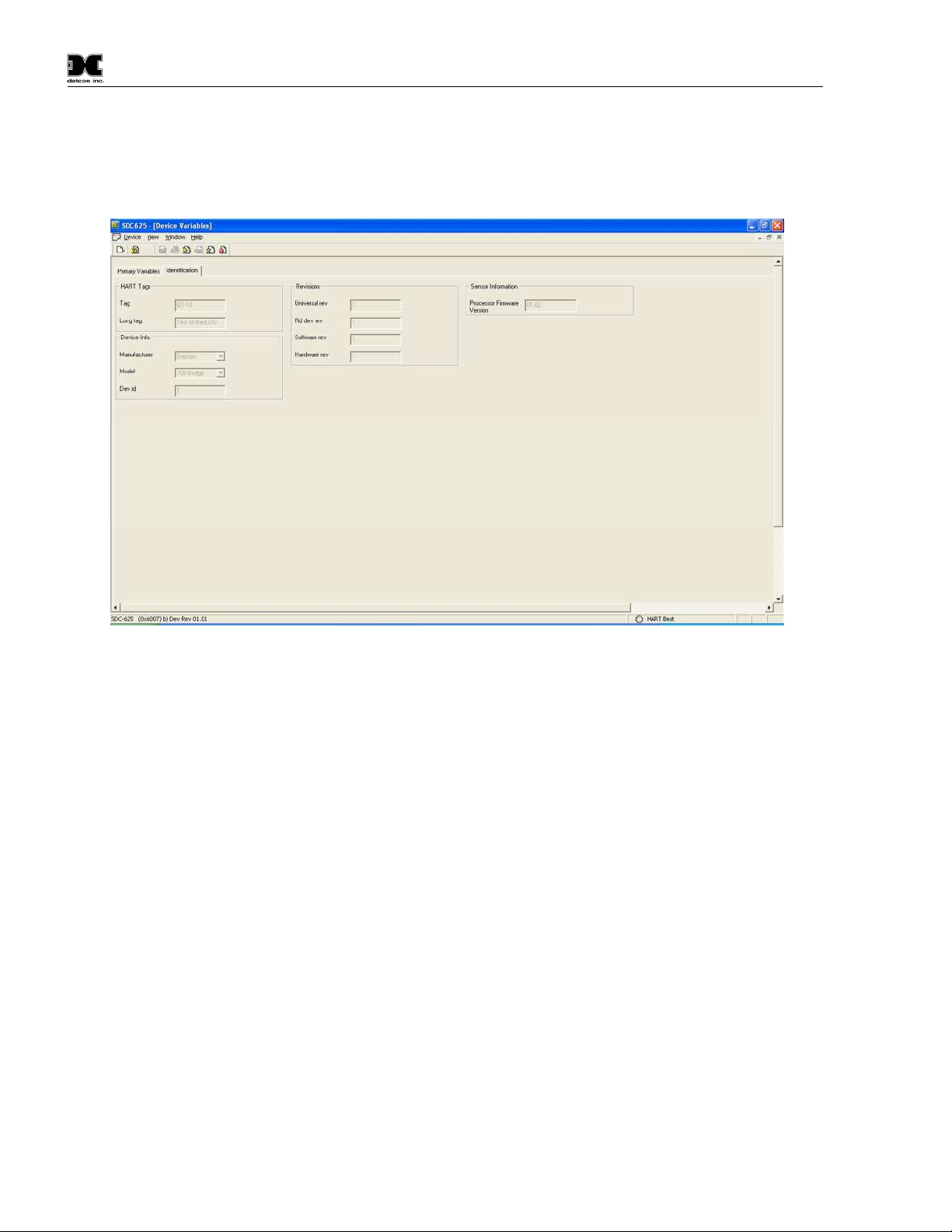
4.4.1.2 Identification
The Identification screen contains 4 sections that provide some basic HART information as well as some
additional sensor information. None of these variables are able to be changed in this screen, although some of
these variables may be changed elsewhere.
Figure 13 Identification
HART Tags
Tag – Text that is associated with the field device installation. This text can be used by the user in any
way. A recommended use is a unique label that correlates to a field device label: a plant drawing, or
on a control system. This variable is also used as a type of data link layer address handle.
Long Tag – Functions exactly like the Tag except the size is larger (max 32 ISO Latin 1 characters).
Device Info.
Manufacturer – Device manufacturer – “Detcon”
Model – Device model – “700 Bridge”
Dev id – Field Device Identification – Uniquely identifies the field device when combined with the
Manufacturer and Model.
Revisions
Universal rev – Revision of the HART Communication Protocol (currently revision 7)
Fld dev rev – Revision of the Field Device Specific Device Description
Software rev – Revision of the software embedded in the HRT Bridge PCA
Hardware rev – Revision of the hardware in the HRT Bridge PCA.
Sensor Information
Processor Firmware Version – Version of the firmware currently loaded in the TP-524D-HRT sensor.
TP-524D-HRT Instruction Manual Rev. 0.3 Page 28 of 48
Page 33
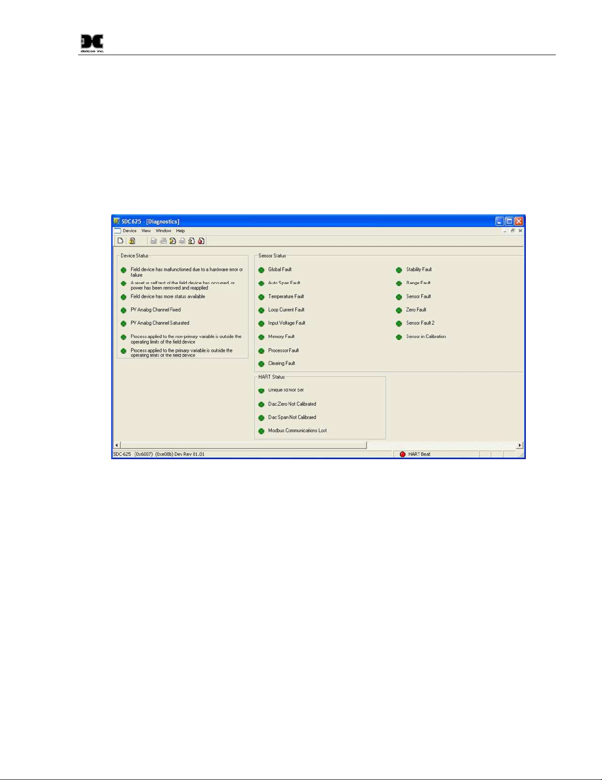
Model TP-524D-HRT
4.4.2 Diagnostics Menu
The Diagnostics Menu contains two screens; 1) Device Status and 2) Channel Status. Both screens consist of
a list of possible device error or status conditions. Next to each status condition is a small icon .that will be
either green to display the normal status, or red to indicate an abnormal, changed, or a malfunction condition.
4.4.2.1 Device Status
Device Status contains one screen that shows the status of the sensor and the HRT Bridge PCA. The left side
of the screen (Device Status) displays the status of the HRT Bridge PCA, with icons that will display either
green to indicate normal condition, or red to indicate an error, a change, or a malfunction.
Figure 14 Device Status Screen
Field device has malfunctioned due to a hardware error or failure
A reset or self test of the field device has occurred, or power has been removed and reapplied
Field device has more status available
PV analog channel fixed
PV analog channel saturated
Process applied to the non-primary variable is outside the operating limits of the field device
Process applied to the primary variable is outside the operating limits of the field device
4.4.2.2 Sensor Status
The Sensor Status section of the screen shows the status of the TP-524D-HRT sensor. Icons are used to
display the status of the sensor and display either green to indicate normal condition or red to indicate an error,
a change, or a malfunction.
Global Fault – The TP-524D-HRT sensor has one or more faults.
Auto span fault – 180 days or more has elapsed since the last successful AutoSpan
Temperature fault – the detector is currently reporting an ambient temperature that is outside of the –
40C to +75C range
TP-524D-HRT Instruction Manual Rev. 0.3 Page 29 of 48
Page 34

Model TP-524D-HRT
Loop current fault – The sensor has detected a condition where the 4-20mA output loop is not
functional
Input voltage fault – The sensor is currently receiving an input voltage that is outside of the 12-
28VDC range
Memory fault – The detector has a failure in saving new data to memory
Processor fault – The detector has an unrecoverable run-time error
Clearing Fault – The sensor reading failed to clear after removal of span gas during an AutoSpan
sequence
Stability Fault – The sensor reading failed to attain a stable reading when span gas was applied during
an AutoSpan sequence
Range Fault – Sensor fails the minimum signal change criteria during an AutoSpan sequence
Sensor fault – The sensor cell has failed
Zero Fault – the sensor drifts below –10% of full range
Sensor Fault 2 – Wheatstone bridge fault
Sensor in Calibration – The sensor is currently being calibrated
4.4.2.3 HART Status
The HART status section of the screen shows the status of the HART interface on the HRT Bridge PCA.
Icons next to each error description indicate if an error has occurred. A green icon indicates the error
condition is not present and a red icon indicates an error has occurred.
Unique ID Not Set – The unique device ID for the HRT Bridge PCA has not been set. This ID is set at
the Detcon factory prior to shipping. If this error occurs, please contact Detcon technical support.
DAC Zero Not Calibrated – The 4mA output of the HRT Bridge PCA has not been calibrated. Please
see Section 4.4.3.4 for calibration instructions
DAC Span Not Calibrated – The 20mA output of the HRT Bridge PCA has not been calibrated.
Please see Section 4.4.3.4 for calibration instructions
Modbus Communications Lost – The TP-524D-HRT sensor has failed to respond to more than 3
Modbus poll requests. This error condition can be reset using the “Reset Comm Lost Status” button
that appears when this error condition occurs.
4.4.3 Device Setup Menu
The Device Status Menu consists of three sub menus that allow parameters within the HRT Bridge PCA, and
within the sensor to be changed or modified, and allows calibration of the sensor.
4.4.3.1 Configuration Setup
The Configuration Screen displays the configuration of the TP-524D-HRT sensor. There are no fields that can
be changed on this screen, these fields are read directly from the TP-524D-HRT sensor.
TP-524D-HRT Instruction Manual Rev. 0.3 Page 30 of 48
Page 35
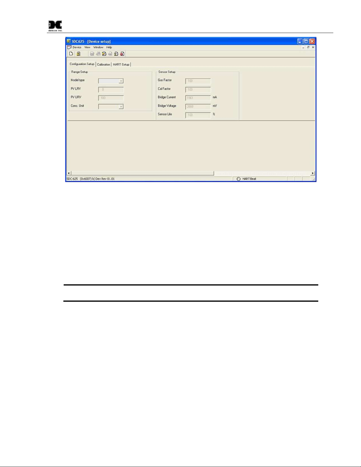
Figure 15 FP Configuration Setup
Model TP-524D-HRT
The Range Set up will display the Model Type of the sensor, followed by the PV LRV (Primary Variable
Lower Range Value) and the PV URV (Primary Variable Upper Range Value), and the Conc Units
(Concentration Units), the display may also show the Sensor Range. The Sensor Setup portion of the screen
will display sensor specific parameters:
Heater Power
Heater Voltage
Sensor Resistance
Heater Current
Sensor Life
NOTE: The values above are read when the HRT Bridge boots up and are not updated
in real-time.
4.4.3.2 Calibration
The Calibration screen displays the days since the last calibration, and the auto span level. This screen also
allows the user to calibrate the sensor by performing an Auto Span Calibration. Calibration of the sensor using
this feature also notifies the Host that the sensor is in calibration mode.
TP-524D-HRT Instruction Manual Rev. 0.3 Page 31 of 48
Page 36
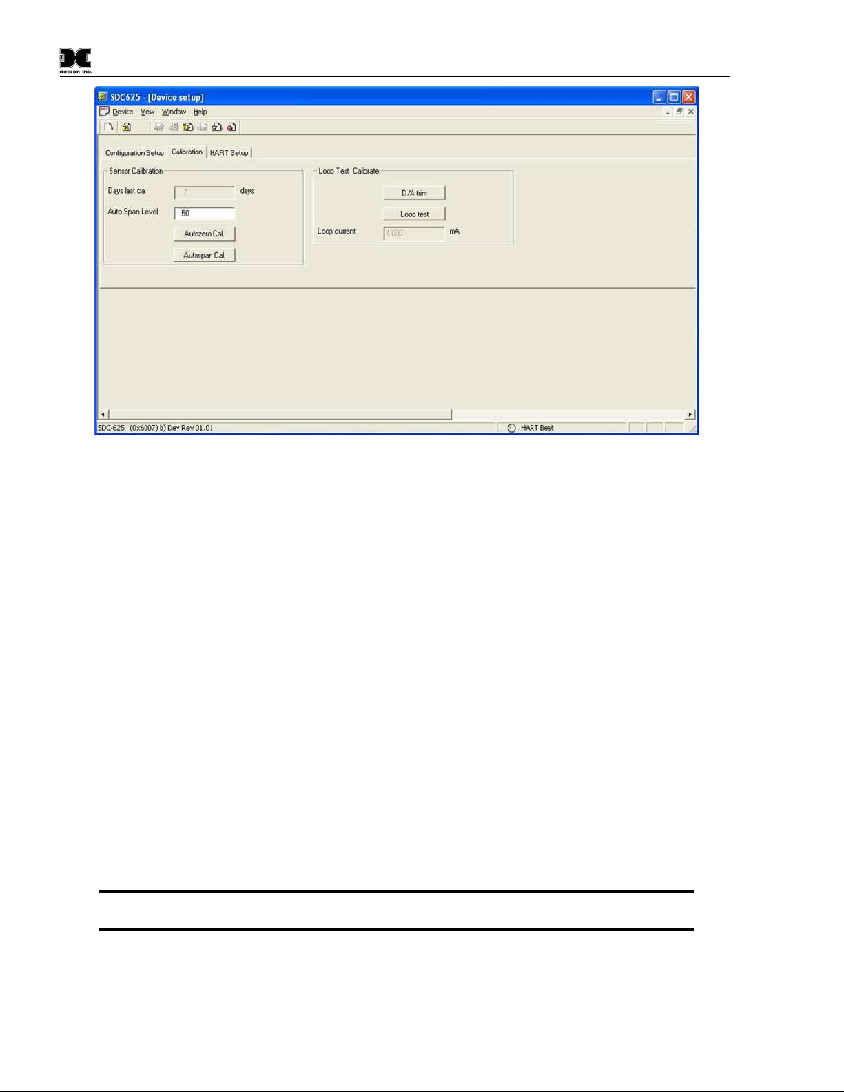
Figure 16 FP Calibration Screen
NOTE:
Model TP-524D-HRT
4.4.3.3 Sensor Calibration using the HRT Bridge
Calibration of a sensor using the HRT Bridge follows the same principle as calibrating the sensor via the
magnetic interface. Since most of the calibration information can be found in Section 3.4 Calibration Mode, it
is important to have the sensor manual on hand when performing sensor calibration.
Auto Zero
Auto Zero function is not used with the TP-524D-HRT Sensor.
Auto Span
The Auto Span function is used to calibrate the sensor. Unless otherwise specified by the associated sensor
manual, span calibration is recommended at 50% of range.
Material Requirements:
Handheld Communicator or PC and interface for HRT Bridge.
Detcon PN 600-610000-000 Splash Guard with integral Cal Port -OR-
-Detcon PN 943-000006-038 Threaded Calibration Adapter
Detcon PN 985-241100-321 In-Line Humidifying Tube
Detcon PN 942-010112-025 H2S Span Gas (recommended) or other suitable span gas source containing
H2S gas in air balance. A fixed flow rate of 200-500cc/min is recommended.
Refer to Section 3.4 Calibration Mode (AutoSpan) for information regarding Span
Gas, flow rates, cross interference, or other sensor specific criteria.
Auto Span consists of entering “Autospan Cal” and following the display. The procedure will ask for the
application of span gas. The applied gas concentration must be equal to the Autospan gas level setting. The
factory default setting and recommendation for span gas concentration is normally 50% of range. If a span gas
containing the recommended concentration is not available, other concentrations may be used as long as they
TP-524D-HRT Instruction Manual Rev. 0.3 Page 32 of 48
Page 37

Model TP-524D-HRT
NOTE 1:
NOTE 2:
NOTE 3:
NOTE 4
NOTE:
NOTE:
NOTE:
fall between 5% and 100% of range. However, any alternate span gas concentration value must be set in the
“Auto Span Level” field before proceeding with “Autospan cal”.
Before performing AutoSpan Calibration, verify that the AutoSpan level matches
the span calibration gas concentration as described in Section 3.5.2 Set AutoSpan Level.
The span gas source must have a normal background concentration of 20.9% O2
(H2S balanced with Air). Pure Nitrogen background mixtures are not acceptable! Significant
span calibration inaccuracies will result.
An H2S gas concentration of 25ppm is strongly recommended for 0-50 and 0100ppm ranges (10ppm span gas for 0-20ppm range). This should be supplied at a controlled
flow rate of 200 to 500cc/min, with 200cc/min being the recommended flow rate. Other
concentrations can be used if as they fall within allowable levels.
: Span gas bottles contain 0% humidity and this ultra-low humidity condition will
cause inaccurate readings when used to calibrate a sensor. To prevent this error, Detcon
prescribes the use of a 24” flexible In-Line Humidifying Tube, which adds the relative
humidity to the span gas. The humidifying tube is not necessary when using a gas generating
calibration device that consists of pumped ambient air and an H2S generating source.
CAUTION: Verification that the calibration gas level setting matches the calibration span gas
concentration is required before executing “Autospan Cal”. These two numbers must be equal. Refer
to the appropriate sensor manual for more information.
1. If applicable install the Calibration Adapter or Splash Guard Adapter with integral Cal Port.
2. Verify that the Auto Span Level is equal to the calibration span gas concentration. If the Auto Span Level
is not equal to the Calibration span gas concentration, adjust the Auto Span Level.
3. Connect the Cal Gas to the sensor, but do not apply the gas.
4. Select “Autospan Cal” from the Sensor Calibration section of the screen.
Upon entering calibration the 4-20mA signal drops to 2mA and is held at this level
until the program returns to normal operation.
5. Upon entering the procedure the procedure will prompt to begin Auto Span Calibration.
6. The procedure will prompt to apply span gas. Apply span gas from the attached cal gas cylinder and
respond to the prompt.
The sensor reading will respond to the gas and will switch to displaying a flashing
“XX”.
Assuming acceptable sensor signal change, after 3 minute the reading will auto-adjust
to the programmed Auto Span level. During the next 30 seconds, the Auto Span sequence
checks the sensor for acceptable reading stability. If the sensor fails the stability check, the
reading is re-adjusted back to the Auto Span level and the cycle repeats until the stability check
is passed. Up to three additional 30-second stability check periods are allowed before the unit
reports a “Stability Fault” twice and the sensor will return to normal operation, aborting the
Auto Span sequence. The sensor will continue to report a “Stability Fault” and will not clear
the fault until a successful Auto Span is completed.
7. If the sensor passes the stability check, the sensor reports a series of messages:
TP-524D-HRT Instruction Manual Rev. 0.3 Page 33 of 48
Page 38
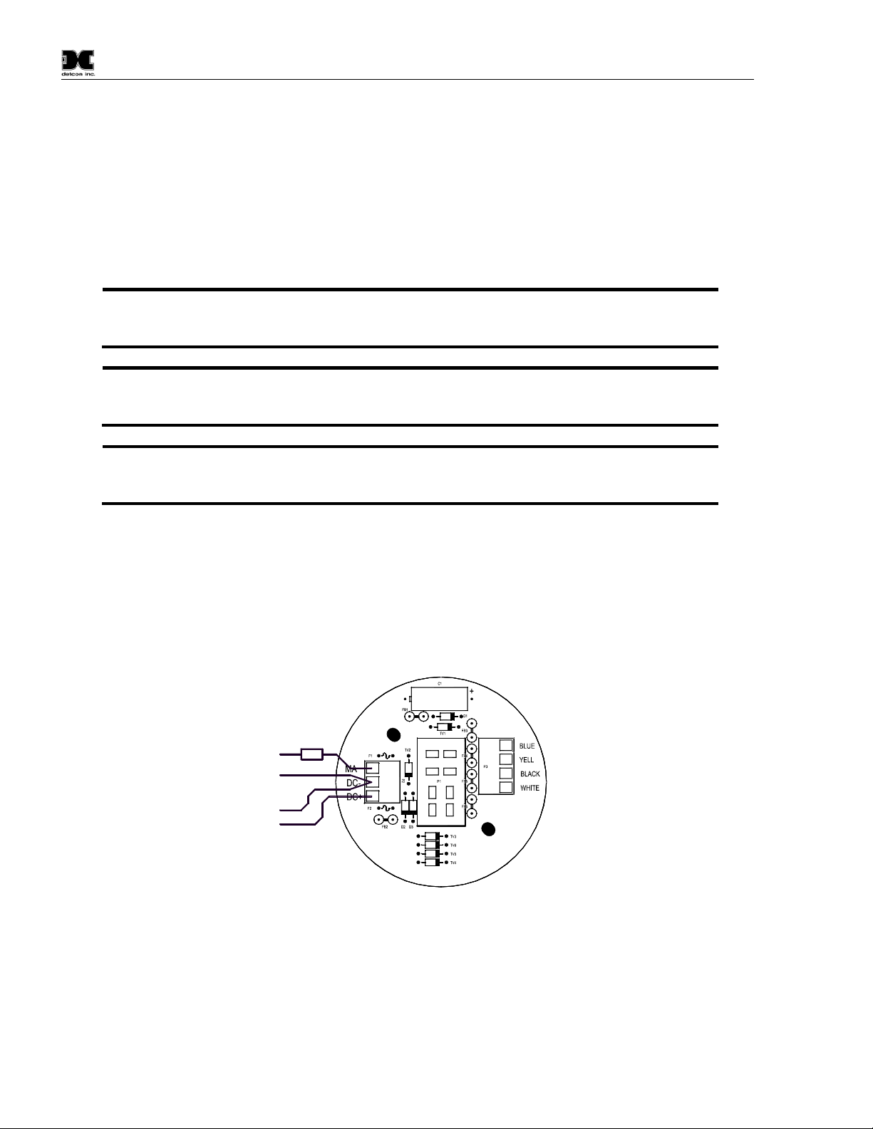
Model TP-524D-HRT
NOTE 1:
“Range Fault”
NOTE 2:
“Stability Fault”
NOTE 3:
Clearing Fault
“AutoSpan Complete”
“Sensor Life XXX%”
“Remove Span Gas”
8. When the sensor passes calibration the procedure will prompt to remove the span gas. Unsuccessful
completion of the span calibration will create a Global Fault, and “Autospan Cal” will be aborted with a
change to the HART Sensor Status (refer to section 4.4.2.2 Sensor Status).
9. After successfully setting span cal the sensor and the HART Interface will return to Automatic Mode.
10. The Auto Span Calibration is complete
11. Remove the cal gas and calibration adapter if applicable.
If the sensor fails the minimum signal change criteria, a
will be
declared and a “Fault Detected” message will be displayed alternately on the sensor with the
current reading. The HART Sensor Status will change to reflect a Range Fault.
If the sensor fails the stability criteria, a
will be declared and a
“Fault Detected” message will be displayed alternately on the sensor with the current reading.
The HART Sensor Status will change to reflect a Sensor Fault.
If the sensor fails the clearing time criteria, a “
” will be declared and
a “Fault Detected” message will be displayed alternately on the sensor with the current
reading. The HART Sensor Status will change to reflect a Clearing Fault.
4.4.3.4 Loop Test Calibrate
The Calibration Screen contains a Loop Test Calibration section. This section displays the loop current
reading and allows the user to perform D/A trim and Loop Test. D/A trim is used to calibrate the 4mA and
20mA set points in the Digital/Analog converter. Loop test allows the user to set the mA output to any level
within range; this can be a good troubleshooting tool for line degradation. A DVM capable of reading
milliamps and a 100~250 Ohm resistor are required to perform D/A trim and/or Loop test.
D/A Trim
1) Select “D/A trim” from the Loop test Calibrate section of the screen.
2) The procedure will prompt to connect a meter: (Refer to Figure 17.)
a) Disconnect the wire from the connector board mA terminal.
b) Connect one end of a 100~250Ohm resistor to the mA terminal.
TP-524D-HRT Instruction Manual Rev. 0.3 Page 34 of 48
DVM +mA
DVM GND
GND (- 24V)
+ 24V
100~250 Ohm
Resistor
Wiring to
LEL Sensor
FP-524D Connector
Board
Figure 17 DVM Connection
Page 39

Model TP-524D-HRT
c) Connect the positive lead of a DVM set to measure milliamps to the other end of the resistor.
d) Connect the negative lead (-) of the DVM to the ‘DC-’ terminal of the connector board.
3) The procedure will set the output to 4ma, and prompt for the DVM Reading. Input the reading and select
“OK”.
4) The HRT Bridge will readjust the output for 4mA, and inquire if the reading is 4mA on the DVM (select
“YES” or “NO”).
5) If the reading on the DVM is 4mA, select “YES” and “OK” and the HRT Bridge will continue on to
20mA. If the reading is not 4mA, select “NO” and “OK” and the procedure will re-run the 4mA
calibration (Step 3).
6) The procedure will set the output to 20mA, and prompt for the DVM Reading. Input the reading and
select “OK”.
7) The HRT Bridge will readjust the output for 20mA, and inquire if the reading is 20mA on the DVM
(select “YES” or “NO”).
8) If the reading on the DVM is 20mA, Select “YES” and “OK”. If the reading is not 20mA, select “NO”
and “OK” and the procedure will re-run the 20mA calibration (Step 6).
9) When both the 4mA and the 20mA have been calibrated the procedure will return the HRT Bridge to
automatic control.
Loop Test
1) Ensure that the DVM is connected as prescribed in Figure 17:
a) Disconnect the wire from the Connector Board mA terminal.
b) Connect one end of a 100~250Ohm resistor to the mA terminal on the connector board.
c) Connect the positive lead of a DVM, set to measure milliamps, to the other end of the resistor.
d) Connect the negative lead (-) of the DVM to the ‘DC-’ terminal of the connectorboard. (Figure 17)
2) Select “Loop test” from the Loop test Calibrate section of the screen.
3) The procedure will prompt for a setting (“4mA”, “20mA”, “Other”, and “End”).
4) Select one of the settings or “End” to exit.
5) If “Other” is selected, the procedure will prompt for a value. Only valid values will be accepted.
6) Select “OK”.
7) The HRT Bridge will set the output for the selected milliamp value.
8) Compare the reading on the DVM to the output displayed. Select “OK” when ready to continue
9) The procedure will return to Step 3. If “End” is selected, the HRT Bridge will exit Loop test and return to
automatic control.
4.4.3.5 HART Setup
The HART Setup Screen allows parameters of the HRT Bridge to be changed or modified. Changes made on
this screen will not be applied until power is cycled on the unit.
TP-524D-HRT Instruction Manual Rev. 0.3 Page 35 of 48
Page 40
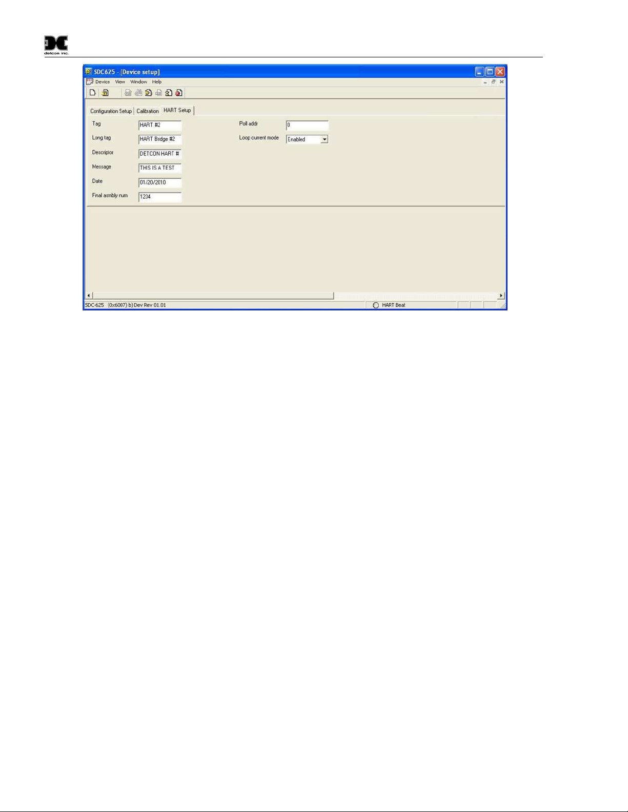
Model TP-524D-HRT
Figure 18 HART Setup
Tag – Text that is associated with the field device installation. This text can be used by the user in any
way. A recommended use is a unique label that correlates to a field device label: a plant drawing, or on
a control system. This variable is also used as a type of data link layer address handle.
Long Tag – Functions exactly like the Tag except the size is larger (max 32 ISO Latin 1 characters).
Descriptor – Text that is associated with the field device. This text can be used by the user in any
way. There is no specific recommended use.
Message – Text that is associated with the field device. This text can be used by the user in any way.
There is no specific recommended use.
Date – Gregorian calendar date that is stored in the field device. This can be used by the user in any
way. There is no specific recommended use. Note: This field is not updated by the HRT Bridge and
does not indicate the current date.
Final asmbly num – Number that is used for identification purposes, and is associated with the overall
field device.
Poll addr – This number is the address of the HRT Bridge on a network and must be set to 0.
TP-524D-HRT Instruction Manual Rev. 0.3 Page 36 of 48
Page 41

Model TP-524D-HRT
NOTE:
NOTE
NOTE
5. Service and Maintenance
Calibration Frequency
In most applications, monthly to quarterly span calibration intervals will assure reliable detection. However,
industrial environments differ. Upon initial installation and commissioning, close frequency tests should be
performed, weekly to monthly. Test results should be recorded and reviewed to determine a suitable
calibration interval. If, after 180 days, an AutoSpan Calibration is not performed, the sensor will generate an
AutoSpan Fault.
Visual Inspection
The Sensor should be inspected annually. Inspect for signs of corrosion, pitting, and water damage. During
visual inspection, the Splash Guard should be inspected to insure that it is not blocked. Examine the porous
316SS flame arrestor within the sensor’s bottom housing for signs of physical blockage or severe corrosion.
Also, inspect inside the Junction Box for signs of water accumulation or Terminal Block corrosion.
Condensation Prevention Packet
A moisture condensation packet should be installed in every explosion proof Junction Box. The moisture
condensation prevention packet will prevent the internal volume of the J-Box from condensing and
accumulating moisture due to day-night humidity changes. This packet provides a critical function and should
be replaced annually. Detcon’s PN is 960-202200-000.
A desiccant cap with a desiccant packet is attached to the sensor cell housing to avoid
damage during storage and shipping. This prevents water from contacting the sensor film, and
as a result helps to retain the stability of the factory span calibration.
: Store the desiccant caps with the desiccant packets in a sealed container (i.e. zip-lock
bag) for future use. It is advisable (but not mandatory) to reinstall the desiccant cap and packet
during prolonged periods without power (more than 1 day is considered “prolonged”). An
active desiccant packet is blue in color and turns pink when consumed. (P/N 960-399800-000
Package of 10)
Replacement of H2S Sensor
: It is necessary to remove power while changing the H2S sensor in order to maintain
area classification while the junction box cover is removed. Proper “Hot Permits” may apply.
a) Remove the junction box cover and remove the Transmitter Module from the Connector PCB.
b) Remove the black, white, blue, and yellow wires coming from the H2S Sensor from the connector PCB.
c) Unthread the H2S Sensor from the junction box and thread the new H2S Sensor onto the junction box.
d) Connect the black, white, blue, and yellow wires from the new H2S sensor to the connector PCB.
e) Reinstall the Transmitter Module, and the junction box cover.
f) Perform “Set Heater Power (Section 3.5.4) to match the new H2S sensor with the Transmitter Module.
g) Perform a successful AutoSpan to match the new H2S sensor with the Transmitter Module (Section 3.4).
TP-524D-HRT Instruction Manual Rev. 0.3 Page 37 of 48
Page 42

Model TP-524D-HRT
NOTE
NOTE
Replacement of Transmitter Module
a) Remove the junction box cover and remove the Transmitter Module from the Connector PCB.
: It is necessary to remove power to the Junction Box while changing the Transmitter
Module in order to maintain area classification.
b) Plug the new Transmitter Module into the connector PCB, and reinstall the junction box cover.
c) Perform Set Range, Set Heater Power, and Set AutoSpan Level then perform a successful AutoSpan before
placing sensor assembly into operation.
Replacement of the Connector PCB
: It is necessary to remove power to the Junction Box while changing the Transmitter
Module in order to maintain area classification.
a) Remove the junction box cover and remove the Transmitter Module from the Connector PCB.
b) Remove the black, white, blue, and yellow wires coming from the H2S Sensor from the connector PCB.
c) Remove the output wiring from the connector PCB terminals labeled DC+, DC-, and MA.
d) Remove the two 6-32 screws holding the Connector PCB to the base of the junction box, and remove the
Connector PCB.
e) Install the new Connector PCB using the two 6-32 screws removed in step d.
f) Re-connect the output wiring to the terminals labeled DC+, DC-, and MA on the connector PCB,
g) Reconnect the black, white, blue, and yellow wires from the H2S Sensor to the connector PCB.
h) Reinstall the Transmitter Module, and the junction box cover.
TP-524D-HRT Instruction Manual Rev. 0.3 Page 38 of 48
Page 43

Model TP-524D-HRT
6. Troubleshooting Guide
Refer to the list of Failsafe Diagnostic features listed in Section 3.6.2 for additional reference in
troubleshooting activities. Listed below are some typical trouble conditions and their probable cause and
resolution path.
Figure 19 Replaceable H2S Sensor
Open Heater
Probable Cause: H2S sensor has failed
Remove H2S sensor wires from the Connector PCB and verify resistance between the black and white wires
using an ohmmeter. At room temperature, the heater film’s normal reading should range between 70 and 90
ohms.
Replace the H2S sensor if open circuit or significantly out-of range readings are found.
Open Sensor
Probable Cause: H2S sensor has failed
Remove H2S sensor wires from the Connector PCB and verify resistance between the blue and yellow wires
using an ohmmeter. At room temperature, the sensor’s normal reading range should be 100 K-ohms to 25
meg-ohms. Failure would be open circuit.
Replace the H2S sensor if an open circuit is found.
AutoSpan Calibration Faults – (Range, Stability, and Clearing)
To clear any AutoSpan Calibration fault, the AutoSpan process must be completed successfully (Section3.4).
Range Fault
Probable Causes: Failed Sensor, Cal Gas not applied or not applied at appropriate time, problems w/ cal gas
and delivery, no Humidifying Tube used, failure to properly desiccant packet the sensor cell during extended
power-off periods.
Check Heater Power Setting (should be 240 ± 5mW at 25ºC ambient temperature).
Verify use of span gas Humidifying Tube.
Check validity of span gas using H2S pull tube or other means (check MFG date on cal gas cylinder).
Check for obstructions through stainless steel flame arrestor (including being wet, blocked, or corroded).
Replace the H2S sensor.
TP-524D-HRT Instruction Manual Rev. 0.3 Page 39 of 48
Page 44

Model TP-524D-HRT
Stability Fault
Probable Causes: Failed Sensor, empty or close to empty Cal Gas Cylinder, problems with cal gas and
delivery, or no Humidifying Tube used, failure to properly desiccant packet the sensor cell during extended
power-off periods.
Check Heater Power Setting (should be 240 ± 5mW at 25ºC ambient temperature).
Verify use of span gas Humidifying Tube.
Check validity of span gas using H2S pull tube or other means (check MFG date on cal gas cylinder).
Check for obstructions through stainless steel flame arrestor (including being wet, blocked, or corroded).
Replace the H2S sensor.
Clearing Fault
Probable Causes: Failed Sensor, Cal Gas not removed at appropriate time or problems with cal gas and
delivery, presence of background H2S, or incorrect Heater Power Setting.
Must recover to < 8ppm in < 5 min after AutoSpan is complete
Use bottled air (zero air) if there is a known continuous H2S background level.
Verify use of span gas Humidifying Tube.
Check validity of span gas using H2S pull tube or other means (check MFG date on cal cylinder).
Check for obstructions through stainless steel flame arrestor (including being wet, blocked, or corroded).
Perform Heater Power Setting.
Replace the H2S sensor.
Poor Calibration Repeatability
Probable Causes: Failed Sensor, use of wrong Cal Gas or problems w/ cal gas and delivery, or Interference
Gases
Check for adequate Sensor Life.
Check Heater Voltage Setting (should be 240±5mW at 25ºC ambient temperature).
Verify use of span gas Humidifying Tube.
Check validity of cal gas using H2S pull tube or other means (check MFG date on cal cylinder).
Check for obstructions through stainless flame arrestor (including being wet, blocked, or corroded).
Evaluate area for presence of any contaminating gases as listed in Section 2.3.
Note the sensor’s serial # and report repetitive problems to Detcon’s Repair Department.
Replace the H2S sensor.
Unstable Output/ Sudden spiking
Possible Causes: Unstable power supply, inadequate grounding, or inadequate RFI protection
Verify Power source is stable.
Verify field wiring is properly shielded and grounded.
Contact Detcon to optimize shielding and grounding.
Add Detcon’s RFI Protection Circuit accessory if problem is proven RFI induced.
Nuisance Alarms
Check condulet for accumulated water and abnormal corrosion on terminal blocks.
If nuisance alarms are happening at night, suspect condensation in condulet. Add or replace Detcon’s
Condensation Prevention Packet P/N 960-202200-000.
Investigate the presence of other target gases that are causing cross-interference erroneous readings.
Determine if cause is RFI induced.
Processor and/or Memory Faults
Recycle power in attempt to clear problem
TP-524D-HRT Instruction Manual Rev. 0.3 Page 40 of 48
Page 45

Model TP-524D-HRT
Restore Factory Defaults - This will clear the processor’s memory and may correct problem. Remember to reenter all customer settings for range and cal gas level after Restore Factory Defaults.
If problem persists, replace the Plug-in Transmitter Module.
Unreadable Display
If due to excessive sunlight, install a sunshade to reduce glare.
Nothing Displayed – Transmitter not Responding
Verify condulet has no accumulated water or abnormal corrosion.
Verify required DC power is applied to correct terminals.
Swap with a known-good Transmitter Module to determine if Transmitter Module is faulty.
Faulty 4-20mA Output
If Sensor has a normal reading with no Faults displayed, and the 4-20 mA signal output is 0mA….
Check that wiring is properly connected at terminal blocks and through to controller inputs.
The 4-20mA output loop must be closed (resistance of < 1000 ohms) to avoid the Loop Fault.
Perform a “Signal Output Check” sequence via Section 3.5.5 and verify 4-20mA output with Current Meter.
Swap with a known-good Transmitter Module to determine if the Transmitter Module’s 4-20mA output circuit
is faulty.
If the 4-20mA current loop is still out of tolerance, contact Detcon at Service@detcon.com, or contact Detcon
customer service.
TP-524D-HRT Instruction Manual Rev. 0.3 Page 41 of 48
Page 46

Model TP-524D-HRT
7. Customer Support and Service Policy
Detcon Headquarters
Shipping Address: 4055 Technology Forest Blvd, Suite 100, The Woodlands Texas 77381
Mailing Address: P.O. Box 8067, The Woodlands Texas 77387-8067
Phone: 888.367.4286, or 281.367.4100
Fax: 281.292.2860
• www.detcon.com
• service@detcon.com
• sales@detcon.com
All Technical Service and Repair activities should be handled by the Detcon Service Department via phone,
fax or email at contact information given above. RMA numbers should be obtained from the Detcon Service
Department prior to equipment being returned. For on-line technical service, customers should have ready the
model number, part number, and serial number of product(s) in question.
All Sales activities (including spare parts purchase) should be handled by the Detcon Sales Department via
phone, fax or email at contact information given above.
Warranty Notice
Detcon Inc. warrants the Model TP-524D-HRT H2S gas sensor to be free from defects in workmanship of
material under normal use and service for two years from the date of shipment on the transmitter electronics
and for a 10 year conditional period on the H2S sensor. See Warranty details in Section 8 TP-524D-HRT
Sensor Warranty.
Detcon Inc. will repair or replace without charge any such equipment found to be defective during the
warranty period. Full determination of the nature of, and responsibility for, defective or damaged equipment
will be made by Detcon Inc. personnel.
Defective or damaged equipment must be shipped to the Detcon Inc. factory or representative from which the
original shipment was made. In all cases, this warranty is limited to the cost of the equipment supplied by
Detcon Inc. The customer will assume all liability for the misuse of this equipment by its employees or other
contracted personnel.
All warranties are contingent upon the proper use in the application for which the product was intended and
does not cover products which have been modified or repaired without Detcon Inc. approval, or which have
been subjected to neglect, accident, improper installation or application, or on which the original identification
marks have been removed or altered.
Except for the express warranty stated above, Detcon Inc. disclaims all warranties with regard to the products
sold. Including all implied warranties of merchantability and fitness and the express warranties stated herein
are in lieu of all obligations or liabilities on the part of Detcon Inc. for damages including, but not limited to,
consequential damages arising out of, or in connection with, the performance of the product.
TP-524D-HRT Instruction Manual Rev. 0.3 Page 42 of 48
Page 47

Model TP-524D-HRT
NOTE
8. TP-524D-HRT Sensor Warranty
H2S Sensor Warranty
Detcon Inc. warrants, under normal intended use, each new H2S sensor (PN 399-800000-000) for a ten year
period under the conditions described as follows: The warranty period begins on the date of shipment to the
original purchaser and ends ten years thereafter. The sensor element is warranted to be free of defects in
material and workmanship. Should any sensor fail to perform in accordance with published specifications
within the warranty period, return the defective part to Detcon, Inc., 4055 Technology Forest Blvd, Suite 100,
The Woodlands, Texas 77381, for necessary repairs or replacement.
First year No Charge
2nd-5thyears $ 25.00 handling charge
6th year $ 60.00 handling charge
7th year $ 90.00 handling charge
8th year $120.00 handling charge
9th year $150.00 handling charge
10th year $180.00 handling charge
Warranty voided $200.00 charge
Non-warranty $295.00 charge
: The warranty will not be honored if evidence shows that the sensor cell was damaged
by moisture exposure due to improper handling and protection during periods of removed
power or storage. The sensor cell must be protected during periods of removed power or
storage by use of a Dust Cap (P/N 602-003306-0TP) and a Desiccant Packet (P/N 960-240010-
000).
Terms & Conditions
* The original serial number must be legible on each sensor element base.
* Shipping point is FOB the Detcon factory.
* Net payment is due within 30 days of invoice.
* Detcon, Inc. reserves the right to refund the original purchase price in lieu of sensor replacement.
Transmitter Module Warranty
Detcon Inc. warrants, under intended normal use, each new Transmitter Module to be free from defects in
material and workmanship for a period of two years from the date of shipment to the original purchaser. All
warranties and service policies are FOB the Detcon facility located in The Woodlands, Texas.
Terms & Conditions
* The original serial number must be legible on each ITM.
* Shipping point is FOB the Detcon factory.
* Net payment is due within 30 days of invoice.
* Detcon, Inc. reserves the right to refund the original purchase price in lieu of ITM replacement.
TP-524D-HRT Instruction Manual Rev. 0.3 Page 43 of 48
Page 48

9. Appendix
9.1 Specifications
Sensor Type: Continuous diffusion/adsorption type
CHEMFET Solid State MOS type
Sensor Life: 5-10 years typical
Measuring Ranges: 0-20ppm, 0-50ppm, or 0-100ppm
Accuracy/ Repeatability: ± 2ppm or ±10% of applied gas (whichever is greater)
Response/Clearing Time: T50 < 30 seconds, T80 < 60 seconds
Outputs: Linear 4-20mA
HART
Electrical Classification: Explosion Proof
CSA and US (NRTL)
Class I, Division 1, Groups B, C, D (Tamb= -40°C to 75°C)
Class I, Zone 1, Group IIB+H2
FM Approvals
Class I, Division 1, Groups B, C, D (Tamb= -40ºC ≤ Ta ≤ 60ºC)
ATEX
EExd IIB+H2 T4 (Tamb= -40ºC ≤ Ta ≤ 60ºC)
Model TP-524D-HRT
Performance Approvals: ISA 92.0.01 Part I-1998;
H2S Performance Requirements
Safety Approvals:
Ingress Protection: NEMA 4X, IP66
Applicable Standards CSA C22.2 No. 30-M1986
Warranty: Electronics – 2 years
Environmental Specifications
CSAUSCSA/NRTL (US OSHA Certified)
C
FM
ATEX
CW Marking
CSA C22.2 No. 142-M1987
UL No. 916
UL No.1203
FM 3810
FM 3600
FM 3615
FM 6340
Sensor – 10 year conditional
Operating Temperature: -40°C to +75°C (-40°F to +167°F)
TP-524D-HRT Instruction Manual Rev. 0.3 Page 44 of 48
Page 49

Storage Temperature: -35°C to +55°C (-31°F to +131°F)
Operating Humidity: 5-100% RH (Non-condensing)
Operating Pressure: Ambient ± 10%
Air Velocity: 0-5 meters/second
Mechanical Specifications
Mechanical Specifications
Dimensions: 10”H (including Splashguard) x 6.1”W x 4.3”D
(254mmH x 155mmW x 109mmD)
3 each ¾”NPT Female Input Ports
¼” Mounting Holes (J-box) 5.5” (140mm) Center to Center.
Weight: 6 lbs. (2.72kg) (with aluminum j-box)
9 lbs. (4.08kg (with Stainless Steel j-box)
Electrical Specifications
Electrical Specifications
Input Voltage: 12-28 VDC
Model TP-524D-HRT
Power Consumption: Normal operation = 68mA (<1.7 watt); Maximum = 85mA (2 watts)
RFI/EMI Protection: Complies with ISO 92.0.01
Analog Output: Linear 4-20mA DC current (1000 ohms maximum loop load @ 24VDC)
0mA All Fault Diagnostics
2mA In-Calibration
4-20mA 0-100% full-scale
22mA Over-range condition
HART Version 7.0
Manufacture ID 0x6007
Device ID 0xE08B
Status Indicators: 4-digit LED Display with gas concentration,
full-script menu prompts for AutoSpan,
Set-up Options, and Fault Reporting
LEDs for Fault and Calibration
Faults Monitored: Heater Fault, Loop Fault, Input Voltage Fault, Sensor Fault,
Processor Fault, Memory Fault, Calibration Fault(s)
Cable Requirements: Power/Analog – 3-wire shielded cable
Maximum distance is 13,300 feet with 14 AWG
TP-524D-HRT Instruction Manual Rev. 0.3 Page 45 of 48
Page 50

9.2 Spare Parts, Sensor Accessories, Calibration Equipment
S in air (for 50 and 100ppm ranges).
Part Number Spare Parts
925-0154DH-100 TP-524D Plug-in Transmitter Module with HRT Bridge
399-800000-000 Replacement H2S sensor
500-005065-007 Standard Connector PCB
960-202200-000 Condensation prevention packet (for J-Box replace annually)
960-240010-000 Desiccant Protection Packet for Cell
960-398800-000 H2S/MOS DRICAP w/desiccant (10 pack)
Sensor Accessories
897-850800-000 NEMA 7 Aluminum Enclosure less cover – 3 port
897-850400-000 NEMA 7 Aluminum Enclosure Cover (Blank)
897-850801-316 NEMA 7 316SS Enclosure less cover – 3 port
897-850401-316 NEMA 7 316SS Enclosure Cover (Blank)
600-610000-000 Sensor Splashguard with integral Cal-Port
943-002274-000 Harsh Location Dust guard
327-000000-000 Programming Magnet
600-003307-000 Dust Cap 7/8" Thread
960-202200-000 Condensation prevention packet (for J-Box replace annually)
960-240010-000 Desiccant Protection Packet for Cell
960-398800-000 H2S/MOS DRICAP w/desiccant (10 pack)
Model TP-524D-HRT
Calibration Accessories
985-241100-321 In-Line Humidifying Tube
943-000006-038 Threaded Calibration Adapter
943-020000-000 Span Gas Kit: Includes calibration adapter, In-Line Humidifying Tube,
200cc/min fixed flow regulator, and carrying case.
(Does Not include gas).
942-010112-010 Span Gas cylinder: 10ppm H2S in air (for 20ppm range)
Contains 58 liters of gas and is good for 80 calibrations
942-010112-025 Span Gas cylinder: 25ppm H
2
Contains 58 liters of gas and is good for 80 calibrations
943-090005-502 200cc/min Fixed Flow Regulator for span gas bottle
Recommend Spare Parts for 2 Years
925-0154DH-100 TP-524D Plug-in Transmitter Module with HRT Bridge
399-800000-000 Replacement H2S sensor
500-005065-007 Standard Connector PCB
960-202200-000 Condensation prevention packet (for J-Box replace annually)
960-399800-000 H2S/MOS DRICAP w/desiccant (10 pack)
TP-524D-HRT Instruction Manual Rev. 0.3 Page 46 of 48
Page 51

Model TP-524D-HRT
9.3 Revision Log
Revision Date Changes made Approval
0.0 12/01/10 Initial Release LBU
0.1 04/23/12 Updated Section 2.6 Field Wiring, load resistor LU
0.2 10/31/13 Added setting LED Alarm Levels LU
0.3 03/10/14 Add notation on use of desiccant pack with sensor cell BM
Shipping Address: 4055 TechnologyForest Blvd, Suite 100, The Woodlands Texas 77381
Phone: 888.367.4286, 281.367.4100 • Fax: 281.292.2860 • www.detcon.com • sales@detcon.com
TP-524D-HRT Instruction Manual Rev. 0.3 Page 47 of 48
Mailing Address: P.O. Box 8067, The Woodlands Texas 77387-8067
Page 52

Model TP-524D-HRT
This page left intentionally blank
Shipping Address: 4055 TechnologyForest Blvd, Suite 100, The Woodlands Texas 77381
Phone: 888.367.4286, 281.367.4100 • Fax: 281.292.2860 • www.detcon.com • sales@detcon.com
TP-524D-HRT Instruction Manual Rev. 0.3 Page 48 of 48
Mailing Address: P.O. Box 8067, The Woodlands Texas 77387-8067
 Loading...