

Detcon Quick Start Guide
Model FP-524D
Combustible Gas Sensor (0-100% LEL)
If equipment is used in a manner not specified by Detcon, the protection provided by
the equipment may be impaired. Applying power with devices hooked up incorrectly
CAUTION
General Installation Notes
Install the sensor only in areas with classifications matching the approval label, and in compliance with local
electrical codes.
Follow all warnings listed on the label.
Mount the FP-524D vertically, with sensor facing down. Locate the sensor with due consideration for the
properties of the gas to be detected, likely sources, ventilation, personnel exposure, and maintenance access.
Ensure that the housing bottom and plug-in sensor are installed during operation. The housing bottom should be
threaded tightly to the sensor housing.
Field Wiring Mounting Installation
may cause damage to the equipment.
After mounting the FP-524D vertically with the sensor pointing straight down, mount the explosion-proof enclosure or
junction box on a wall or pole. When mounting on a pole, secure the junction box to a suitable mounting plate and
attach the mounting plate to the pole using U-bolts.
NOTE
Do not use Teflon tape or any other type of pipe thread material on the ¾-in. threads unless the
unit is mounted in a severe or harsh environment. Metal-on-metal contact must be maintained to
provide a solid electrical ground path. If Teflon tape is used, the sensor must be externally
grounded using a ground strap.
Sensor Connector PCB
NOTE
NOTE
1. Remove the junction box cover and unplug the Transmitter Module.
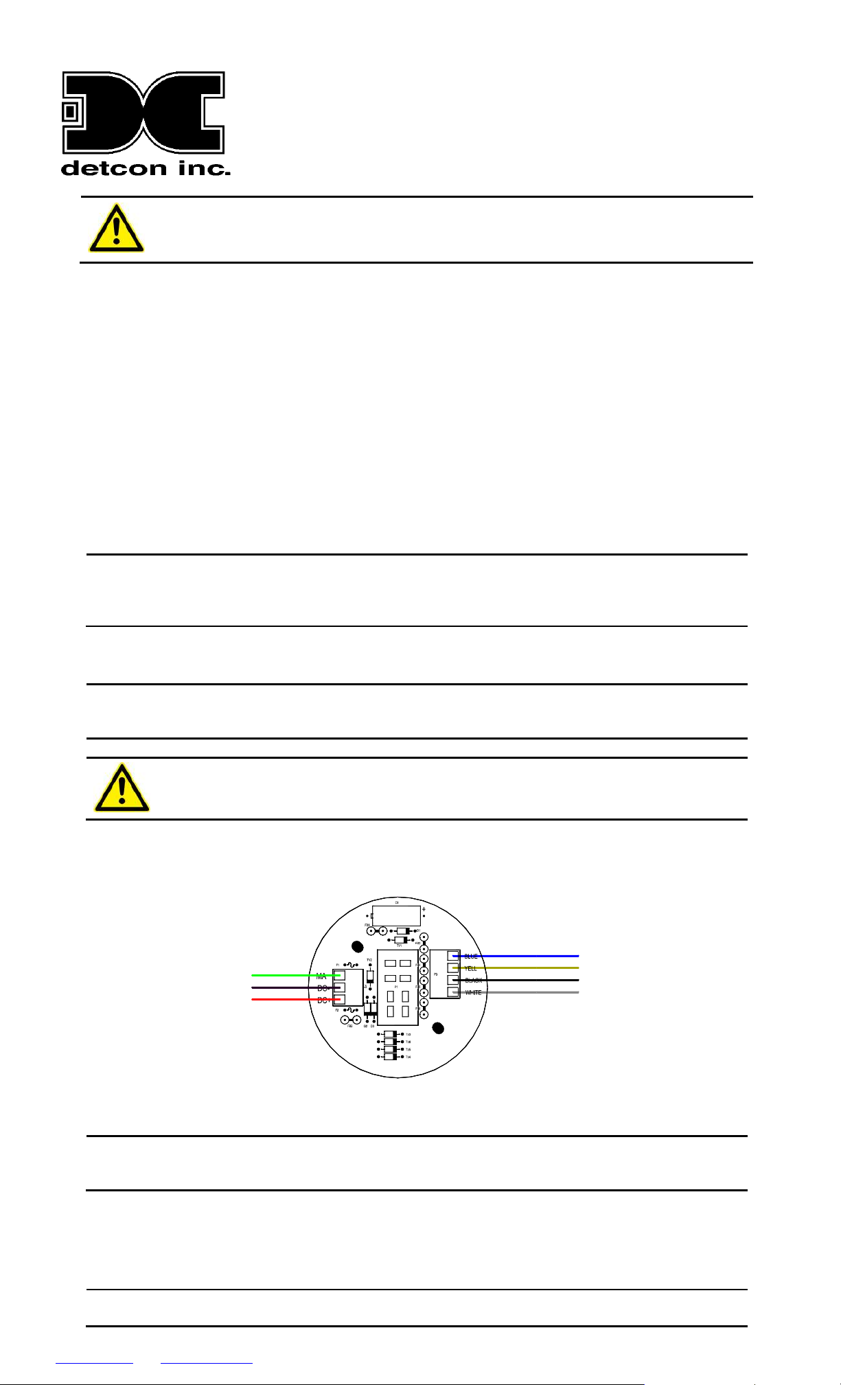
2. Observing correct polarity, terminate the three-conductor 4-20mA field wiring (DC+, DC-, and MA) to the sensor
assembly wiring in accordance with the detail shown in Figure 1.
Shielded cable is required for installations where cable trays or conduit runs include high
voltage lines or other possible sources of induced interference. Separate conduit runs are highly
recommended in these cases.
The supply of power should be from an isolated source with over-current protection.
Do not apply System power to the sensor until all wiring is properly terminated.
CAUTION
Blue
Yellow
Black
White
Wiring to
LEL Sensor
NOTE
mA
Ground
Power
Customer
Wiring
Figure 1 FP-524D Sensor Connector PCB
A 6-32 or 8-32 threaded exterior ground point is provided on most junction boxes for an external
ground. If the Sensor Assembly is not mechanically grounded, an external ground strap must be
used to ensure that the sensor is electrically grounded.
3. Trim and cap all exposed wire leads if they are not permanently landed in the terminal board.
4. Plug the Transmitter Module into the connector PCB and replace the junction box cover.
Remote Mounting Installation
NOTE
If using the FP-524D remote-mount configuration (sensor model FP-524D-RS and transmitter
model FP524D-RT), follow the specifications for maximum separation in Table 1 and refer to the
www.detcon.com service@detcon.com 713.559.9200 FP-524D Quick Start Guide April 23, 2014 • Document #4462 • Revision 1.1
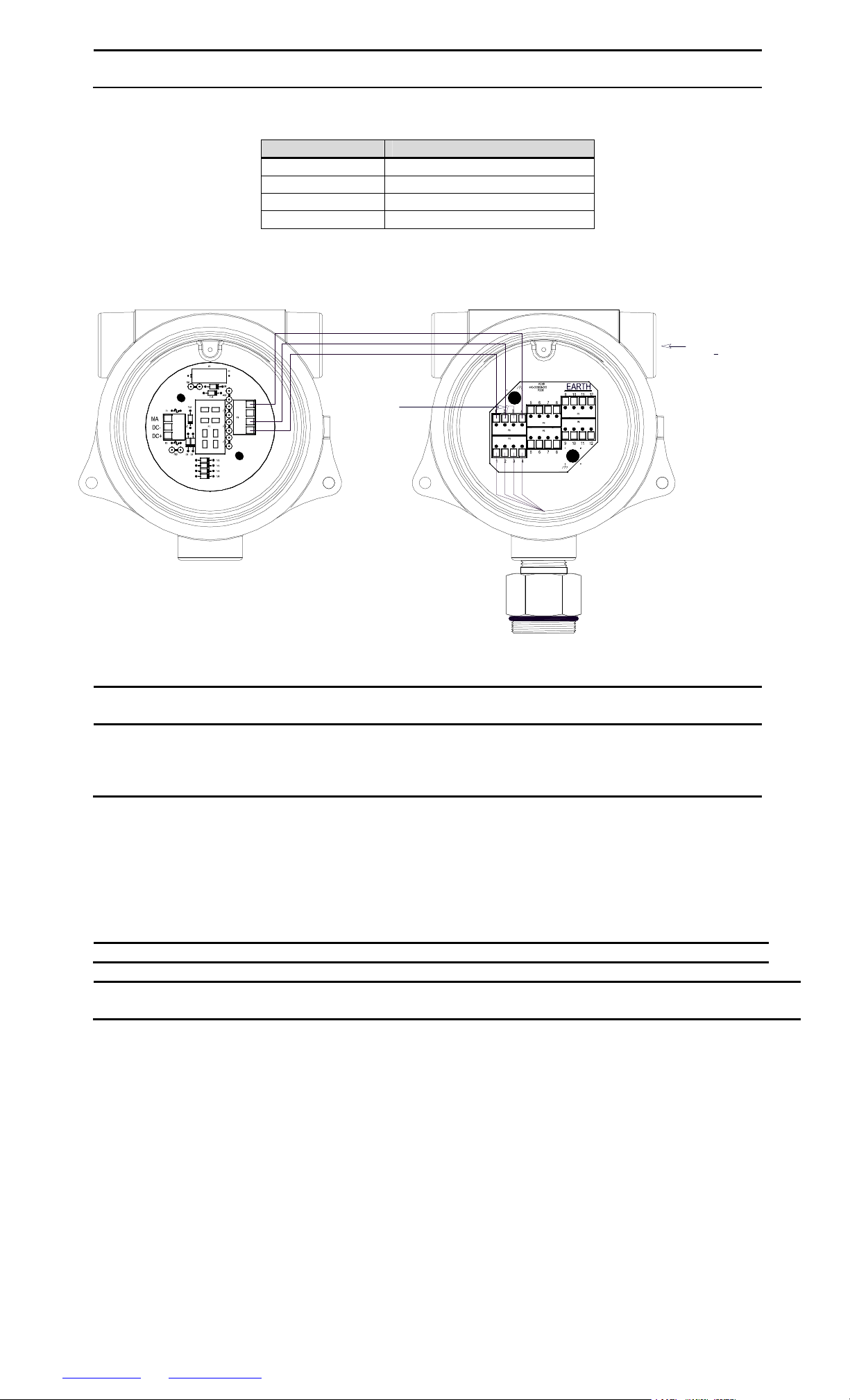
wiring diagram in Figure 2. There is a limit 0.5-ohm maximum resistance drop per wire over the
separation distance.
Table 1 FP-524D Remote Sensor Maximum Separation
AWG Maximum Separation (feet)
20 50
18 75
16 125
14 175
Remote Transmitter
FP-524D-RT
Blue
Black
White
Remote Sensor
FP-524D-RS
Blue
Black
Install
Jumper
Figure 2 FP-524D Remote Sensor Wiring Diagram
White
Yellow
White
Black
Blue
Plug unused port
3
with
" NPT plug
4
Measure Bridge Voltage
From White (1) to Blue (4)
Target Voltage is 2.7V
NOTE
A jumper is required on the remote sensor connector board. Failure to install this jumper will
cause a sensor fault condition.
NOTE
For remote-mounted sensors, different lengths of cables will have varying amounts of resistance,
which will shift the sensor bridge voltage. Therefore, the bridge voltage must be adjusted after
initial power up. This adjustment is only required after initial installation and will not be
necessary thereafter (except in case of replacement of the plug-in sensor).
Initial Start Up
1. Upon completion of all mechanical mounting and termination of all field wiring, apply system power in the range
of 12-28VDC (24VDC typical) and observe the following normal conditions:
a. FP-524D display reads “0” and no fault messages are flashing.
b. A temporary upscale reading may occur as the sensor heats up. This upscale reading will decrease to 0%
within 1-2 minutes of power-up, assuming there is no gas in the area of the sensor.
NOTE
2. After a warm up period of 1 hour, check the sensor to verify sensitivity to combustible gas.
NOTE
a. Attach the calibration adapter to the threaded sensor housing.
b. Apply the test gas at a controlled flow rate of 200–500 cc/min (200 cc/min is the recommended flow).
c. Allow 1-2 minutes for the reading to stabilize.
d. Observe that the display increases to a level near that of the applied calibration gas value during the 1-2
minutes.
e. Remove test gas and observe that the display decreases to zero.
3. Initial operational tests are complete. Detcon FP-524D combustible gas sensors are factory-calibrated prior to
shipment and should not require significant adjustment at start-up. However, it is recommended that a complete
calibration test and adjustment is performed 16 to 24 hours after power-up.
The 4-20mA signal is held constant at 4mA for the first 2 minutes after power-up.
Do not use calibration gases in nitrogen background gas mixtures. This will cause significant reading
inaccuracies.
www.detcon.com service@detcon.com 713.559.9200 FP-524D Quick Start Guide April 23, 2014 • Document #4462 • Revision 1.1
 Loading...