

Page 1

d
etcon inc.
Detcon Model FL10
Single Channel Flame Detector Control Module
Operator’s Installation & Instruction Manual
May 11, 2005 • Document #3139 • Version 1.1
phone 888-367-4286, 281-367-4100 • fax 281-292-2860 • www.detcon.com • sales@detcon.com
Page 2

Table of Contents
2.0 Description
2.1 Specifications
2.2 Controller Models
2.3 Alarm Functions and Controller Configuration
2.4 Controller Operation and Menu Selections
2.5 Power Input Options
2.6 Analog 4-20 mA Signal Input/Output
2.7 RS-485 Modbus™ Specifications
2.8 Fault Circuit Functions
2.9 Other Features
2.10 Controller Calibration
2.11 Warranty & Service Policy
Model FL10 Single Channel Flame Detection Control Module PG.2
Page 3
2.0 DESCRIPTION
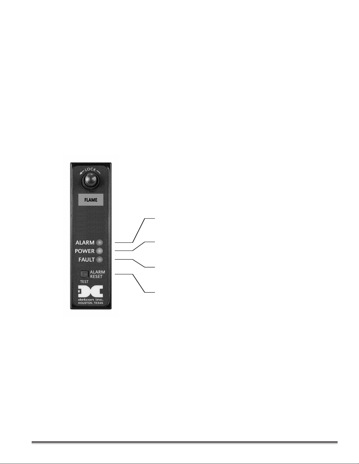
Alarm set points — Alarm 1 and Alarm 2 are preset to activate
when the input signal exceeds 18 mA. Both Alarm 1 and
Alarm 2 share the same alarm front panel LED indicator.
The fault alarm, depending on the switch programmable
configuration, will activate on loss of power, internal power
supply fault, or 0 mA fault signal from flame detector.
The alarm reset switch resets alarms that have been programmed latching. It also acts as an alarm relay test function.
Power - LED indicator
Detcon Model FL10 single Flame detector digital control modules are designed to supervise and display the status of a
single remote Flame detector assembly with 4-20 mA input. Model FL10 Series control modules are designed to operate
on an input voltage of 24 VDC and are compatible with a complete line of Detcon enclosures and mainframe hardware
assemblies. The available enclosures include designs for rack or panel mounting in non-hazardous areas (NEMA 1), for
weather proof outdoor location in non-hazardous areas (NEMA 4), and for location in areas electrically classified hazardous or explosion proof (NEMA 7).
Any combination of Model FL10
installed in a common mainframe assembly thereby providing monitoring for fire and gases. Model FL10 control modules
are compatible with a linear 4-20 mA DC input signal. The module features RS-485 Modbus™ serial output, 4-20 mA analog
signal output, and 3 alarm relays that are status displayed via light emitting diodes located on the front panel. Alarm functions are alarm 1 and alarm 2, and fault (alarms 1 and 2 share the same alarm LED indicator). All alarms are switch programmable for latching or non-latching operation with a common front panel reset switch. The reset is part of a common bus
when installed in a mainframe, allowing for the use of an external reset switch common to all modules in the mainframe.
Flame detector
control modules and Detcon gas sensor Model 10 control modules may be
TIONS
2.1 SPECIFIC
Range
4-20 mA input from flame detector.
Accuracy/Repeatability (4-20 mA)
± 2% F.S.
ating T
Oper
–40° F to +175° F
Input Power
24 VDC standard; 12 VDC optional
Power Consumption (per channel)
Normal: 0.8 w
Full Alarm: 1
*Control module only. See sensor product literature for power per flame detector.
A
per
em
atts*
.7 watts*
atur
e
Model FL10 Single Channel Flame Detection Control Module PG.3
Page 4

Warranty
Alarm Reset/Test
Relay Output
Configuration
Dip Switches
SW2 SW3
Serial ID
Address Setting
Dip Switches
SW2
Two years
Five year fixed fee service policy
Outputs
Analog 4-20 mA DC
Serial RS-485 Modbus™
Relays
Contacts include common, normally open, and normally closed for three alarms
Resistive load: 5A, 250 VAC; 5A, 30 VDC
Inductive load: 2A, 250 VAC; 2A, 30 VDC
Max. operating current: 5A
2.2 CONTROLLER MODELS
The label on the Model FL10 face plate is red. It can be used with any industry standard 4-20 mA f lame detector.
2.3 ALARM FUNCTIONS AND CONTROLLER CONFIGURATION
Model FL10 control modules incorporate several user selectable alarm programming options and general operating
op
tions t
hat are accom
plished via dip switc
and alarm firing direction. Reference the figure below for the applicable dip switch locations and settings.
hes. These options include latching of relays, energized/de-energized relays,
22..33..11 LLaattcchhiinngg oorr nnoonn--LLaattcchhiinngg RReellaayys
All alar
ms — alar
m 1, alarm 2, and fault — can be jumper programmed to operate as latching or non-latching. If an
s
alarm is programmed to latch, its corresponding relay and LED indicator, once activated, will stay activated until the
reset button is pressed (assuming, of course, that alarm conditions have cleared).
To program an alarm for latching operation, slide its corresponding switch to the on position. For non-latching operation slide the switch to the off position. The switch locations are as follows: fault – SW2-2, alarm 1 - SW2-8, and alarm
2 – SW2-5.
Model FL10 Single Channel Flame Detection Control Module PG.4
Page 5

22..33..22 EEnneerrggiizzeedd oorr DDee--eenneerrggiizzeed
All alarms relays — alarm 1, alarm 2, and fault — can be switch programmed as normally energized or normally de-energized. The standard is de-energized. However, a relay can be programmed as energized to provide application specific
features. A normally energized relay will de-energize when in alarm. A typical application of the energized configuration
is to have the fault relay normally energized so that in the event of a power failure to the control module card, the fault
relay will de-energize causing its relay contacts to change state, thereby creating a fault output.
It must be noted that when an alarm relay is jumper programmed as normally energized, the contact outputs, normally
open and normally closed, become reversed. The normally open contact becomes the normally closed and vice versa.
Reconfiguration of the contact output jumpers may be required.
To program an alarm for normally energized operation, slide its corresponding switch to the “on” position. For normally de-energized operation slide the switch to the “off” position. The switch locations are as follows: fault – SW2-1, alarm
1 - SW2-7, and alarm 2 – SW2-4.
d
22..33..33 AAsscceennddiinngg oorr DDeesscceennddiinngg AAllaarrmms
m 1 and alarm 2 can be switch programmed to operate during ascending or descending gas conditions. For flame
Alar
detection this will always be set for ascending.
o program an alarm for ascending gas conditions, slide its corresponding switch to the “on” position. For descending gas
T
conditions slide the switch to the “off” position. The switch locations are as follows: alarm 1 - SW2-6, and alarm 2 – SW2-3.
22..33..77 AAllaarrmm RReesseet
An alarm reset switch (SW1), located on the control module face plate is used to reset alarms that have been programmed as latc
switch and releasing it.
Remote reset outputs are also a feature of the Model FL10 control module. This feature is available when used in conjunction with Model FL10 compatible control enclosures and mainframe motherboards.
t
hing. Once alarm conditions have cleared, alarms may be reset by simply pushing the momentary
s
2.4 CONTROLLER OPERATION AND MENU SELECTIONS
Upon applying power the controller will then enter normal operation mode. There is a 15 second period after power-up
ed.
e ignor
in which alar
22..44..11 TTeesstt MMoodde
Besides acting as an alar
switch for 10 seconds. Both alarm relays will then activate for 5 seconds and then clear.
2.5 PO
Standard operating input power of the Model FL10 control module is 24 VDC unless 12 VDC is specified at time of order. All
of the circuitry of the Model FL10 control module, with the exception of relays, will operate on 12 or 24 VDC.
ms ar
e
WER
INPUT OPTIONS
t, the front panel switch is used to test the alarm relays. To activate the test, hold the
ese
m r
erted to a 12 VDC control module by changing the relays. If this is desired, it is
4 VDC contr
A 2
recommended that the control modules be returned to Detcon to be converted. However, if technical personnel are
used, the 24 VDC relays (OMRON #G6B-2114P-US-DC24) may by replaced by 12 VDC relays (OMRON ##G6B-2114PUS-DC12) at the owner’s discretion. Caution: note that the only identif ication for required input power is the labeling
on the alarm relays.
2.6 AN
The Model FL1
and is calibrated so that a 4 mA input will provide a 4 mA output and a 20 mA input will provide a 20 mA output.
This circuitry is factory set. Should adjustment become necessary, refer to the controller calibration section (section
2.10).
ol module can be con
ALOG
4-20 MA SIGNALINPUT/OUTPUT
es an analog 4-20 mA signal in
eceiv
0 r
v
put. The signal is processed through an analog to digital converter
Model FL10 Single Channel Flame Detection Control Module PG.5
Page 6

2.7 RS-485 MODBUS™ FEATURES AND SPECIFICATIONS
Register 40005 Status Bits
MSB LSB
Alarm 1 status
Alarm 2 status
Fault status
Fault energized
Fault latching
Alarm 2 ascending
Alarm 2 energized
Alarm 2 latching
Alarm 1 ascending
Alarm 1 energized
Alarm 1 latching
Not used
Test mode status
Model FL10 control modules feature Modbus™ compatible communications protocol and are addressable via the programming menu for multi-point communications. Communication is two wire, half duplex, with the Model FL10 control module set up as a slave device. A master controller up to 4000 feet away can theoretically poll up to 256 different
Model FL10 control module cards. This number may not be realistic in harsh environments where noise and/or wiring
conditions would make it impractical to place so many devices on the same pair of wires. If a multi-point system is
being utilized, each control module should be set for a different address. Typical address settings are: 01, 02, 03, 04, 05,
06, 07, 08, 09, 0A, 0B, 0C, 0D, 0E, 0F, 10, 11, etc.
Model FL10 control module ID numbers are set via the SW3 dip switch bank as described in 2.4.3.
The following register list describes the parameters available from the Model FL10 control module:
40000 Not Used
40001 mA Input Reading 0-2000 (0 to 20.00 mA)
40002 Not Used
40003 Not Used
40004 Not Used
2.8 FAULT CIRCUIT FUNCTIONS
Model FL10 control modules feature fail safe supervisory circuits designed to assure maximum reliability in system perfor
mance. A f
is if the fault relay is jumper-programmed as normally energized, a loss of external 24 VDC power or the internal 5
VDC supply will cause the relay to de-energize but the LED will not illuminate. Below is a list of conditions that will
cause a f
1. Loss of 24 VDC power to the Model FL10 control module (only if relay is programmed as normally energized).
2. Open po
3. Open signal loop from the control module to the flame sensor.
4. Loss of the internal 5 VDC supply (only if relay is programmed as normally energized).
5. Signal level drift below 2.4 mA from the flame sensor.
ault alar
w
ault condition will cause the fault LED to illuminate and the fault relay to actuate. The exception to this
m:
er loop fr
om t
he contr
ol module t
Model FL10 Single Channel Flame Detection Control Module PG.6
he flame sensor.
o t
Page 7

2.9 OTHER FEATURES
M
odel FL10 control modules include other features which are discussed below.
2.9.1 PolySwitch Overcurrent Protection
Model FL10 control modules incorporate PolySwitch overcurrent protection components that act as resetable fuses. The
PolySwitch circuit protector is a positive temperature coefficient resistor that undergoes a large, abrupt change in resistance when an overcurrent or high temperature heats it above a specific point. Normally just tens of milliohms, the
resistance of the PolySwitch protector increases orders of magnitude when switched. This increase limits current to several milliamps.
When the current or temperature fault that caused the device to switch has been substantially reduced, the PolySwitch
device resets, allowing normal circuit operation to resume. The protector requires no manual resetting or replacement.
Four separate Poly Switches monitor and protect the following circuitry: the 4-20 mA signal input loop, the 4-20 mA
output signal loop, the 24 VDC input power loop, and the 24 VDC output power loop to the sensor.
2.10 CONTROLLER CALIBRATION
The 4-20 mA output of the Model FL10 control module is calibrated at the factory and should require no further adjustment. If under some special circumstance calibration is required, contact Detcon for assistance.
2.11 WARRANTY AND SERVICE POLICY
tcon, Inc., as manufacturer, warrants each new Model FL10 series digital electronic control module to be free from
De
defects in material and workmanship under intended normal use for a period of two years from date of shipment to the
original purchaser. Detcon, Inc., additionally provides for a fixed fee repair/replace service policy which covers Model
FL10 ser
tory repair for the period following the one-year warranty period and shall end f ive years after expiration of the warranty. The fixed policy rate is $75.00 per control module, per transaction, during the period of the policy. The policy is
FOB Detcon, Inc., The Woodlands, Texas.
ies digit
al control modules for a period of five years. The fixed fee service policy shall affect any necessary fac-
Shipping Address: 3200 A-1 Research Forest Dr., The Woodlands, Texas 77381
Mailing Address: P.O. Box 8067, The Woodlands, Texas 77387-8067
phone 888-367-4286, 281-367-4100 • fax 281-292-2860 • www.detcon.com • sales@detcon.com
Model FL10 Single Channel Flame Detection Control Module PG.7
 Loading...