

®
B-VENT DECORATIVE GAS FIREPLACE
OWNER’S OPERATION AND INSTALLATION MANUAL
EVGL850N (NATURAL) ELECTRONIC IGNITION
WARNING: If the information in these instructions is not followed exactly, a fire or explosion
may result causing property damage, personal
injury or death.
FOR YOUR SAFETY
— Do not store or use gasoline or any other flam-
mable vapors or liquids in the vicinity of this or
any other appliance.
— WHAT TO DO IF YOU SMELL GAS :
• Do not try to light any appliance.
• Do not touch any electrical switch;
• Do not use any phone in your building.
• Immediately call your gas supplier from a
neighbor’s phone. Follow the gas supplier’s
instructions.
• If you cannot reach your gas supplier, call the
fire department.
— Installation and service must be performed by a
qualified installer, service agency, or the gas
supplier.
SAVE THIS BOOK
This book is valuable. In addition to instructing
you on how to install and maintain your appliance, it also contains information that will
enable you to obtain replacement parts or
optional accessory items when needed. Keep
it with your other important papers.
WARNING: Improper installation,
adjustment, alteration, service or
maintenance can cause injury or
property damage. Refer to this
manual. For assistance or additional
information consult a qualified installer, service agency, or the gas
supplier.
NOT FOR USE WITH SOLID FUEL
CHECK LOCAL CODES PRIOR TO
INSTALLATION
This appliance may be installed in an aftermarket* manufactured (mobile) home, where not prohibited by state
or local codes.
This appliance is only for use with the type of gas indicated on the rating plate.
This appliance is not convertible for use with other gases, unless a certified kit is used.
*Aftermarket: Completion of sale, not for purpose of resale, from the manufacturer.
Save this manual for future reference.
EVGL850N
®
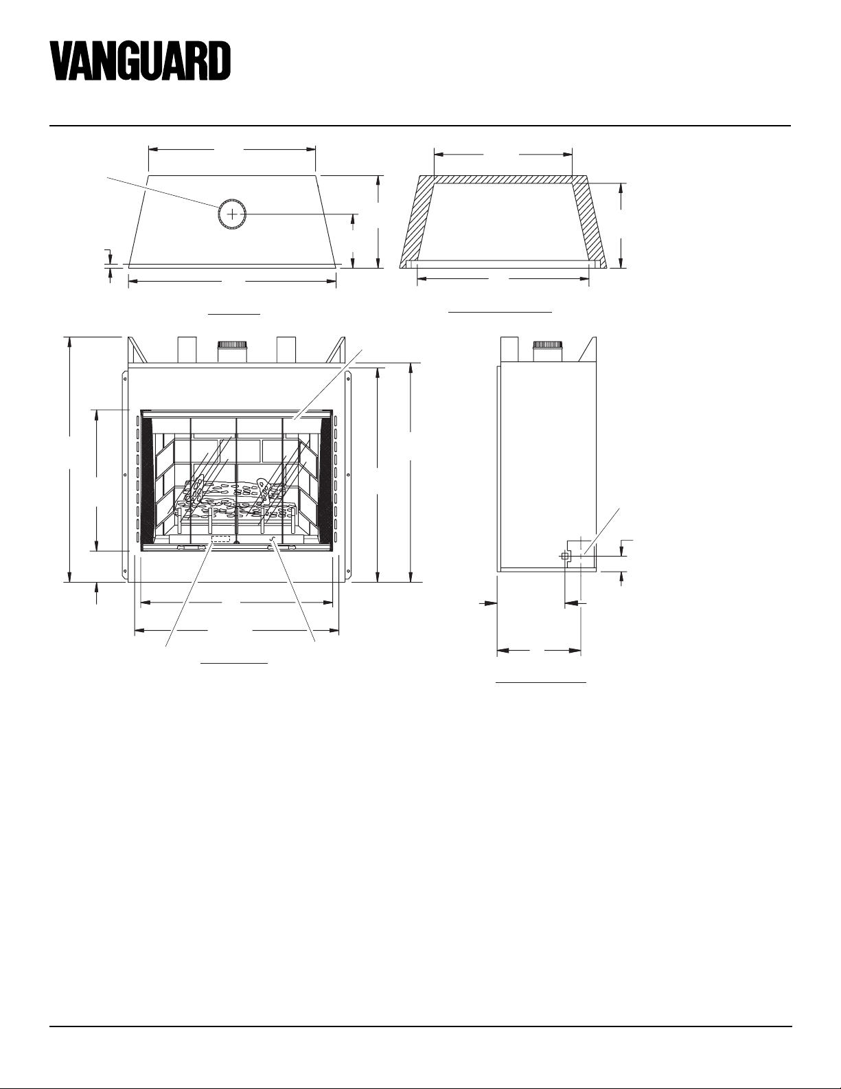
VENTED TYPE DECORATIVE APPLIANCE
For Use With
5" ø Type B-1
29"
(737mm)
Vent Pipe
Only
5/8"
(16mm)
36"
(914mm)
TOP VIEW
1
/8"
38
(968mm)
3
/4"
21
(552mm)
7
4
/8"
(124mm)
32"
(813mm)
13
33
(859mm)
Control Valve (Behind
Control Access Door)
FRONT VIEW
Figure 1 - Appliance Dimensions
/16"
3
15
/8"
(391mm)
9"
(229mm)
Glass Door
34
(870mm)
3
33
/8"
(848mm)
Control Access Door
HEARTH AREA
DIMENSIONS
FRONT INSIDE VIEW
1
/4"
1
22
/2"
(572mm)
27"
(686mm)
3
10
/4"
(273mm)
Left Side
9 3/4"
(248mm)
Right Side
13"
(330mm)
RIGHT SIDE VIEW
5
/8"
9
(244mm)
Outside Air
Kit Location
(Optional)
3
2
/8"
(60mm)
2
107050
OWNER’S MANUAL
INTRODUCTION
Model EVGL850N is a radiant heat decorative gas appliance that use an electronic gas
control valve with electronic ignition system. A 5” B-Type venting system and a
listed type vent cap are not supplied but are
required for proper operation. See venting
instructions on pages 6 and 7.
WARNING: This gas appliance must not be connected to a
chimney flue servicing a solid
fuel burning appliance.
• Model EVGL850N uses NATURAL
GAS ONLY.
If you have any doubts as to which gas your
particular unit is approved and tested for use
with, please check the rating plate located
behind the control access door (Figure 1,
page 2).
BEFORE YOU BEGIN
Before beginning the installation of your
appliance, read these instructions through
completely.
This DESA appliance and its approved components are safe when installed according to
this installation manual and are operated as
recommended by DESA. Unless you use
DESA approved components tested for this
appliance, YOU MAY CAUSE A FIRE
HAZARD!
The DESA warranty will be voided by, and
DESA disclaims any responsibility for the
following actions :
A) Modification of the appliance or any of
the components.
B) Use of any component part not ap-
proved by DESA in combination with
this appliance.
C) Installation and/or operation in a man-
ner other than instructed in this manual.
D) The burning of anything other than the
type of gas approved for use in this gas
appliance.
This appliance, when installed, must be
electrically grounded in accordance with
local codes or, in the absence of local codes,
with the National Electrical Code, ANS/
NFPA 70 or the Canadian Electrical Code,
CSA C22.1.
The installation must conform with local
codes or, in the absence of local codes, with
the current National Fuel Gas Code, ANS
Z223.1 or with the current CAN/CGA B149
Installation Codes.
This appliance complies with ANS Z21.501998 and CSA 2.22-M98 as Vented Gas
Fireplaces and is listed and tested by the
Canadian Standards Association to the
above test standards.
WARNING: Installation of this
appliance must be done by a qualified service person well trained
in the installation of such appliances. You will also need a building permit from your local Building and Safety Commissioner
before installing this appliance;
otherwise your insurance co. may
not cover this appliance.
GAS RATING
Type of Gas Natural
Max. Input Rating: 21,000 Btu/hr
Manifold Pressure: 3.5 in. WC (.87 kPa)
Minimum Supply Pressure: 4.5 in. WC (1.12 kPa)
Maximum Supply Pressure: 10.5 in. WC (2.66 kPa)
Orifice Size: # 45
This appliance is not intended to
be used as a primary source of
heat.
CAUTION: Do not connect
appliance before pressure testing gas piping. Damage to gas
valve may result and an unsafe
condition may be caused.
The appliance and it’s individual equipment
shutoff valve must be disconnected from the
gas supply piping system during any pressure testing of that system at test pressures
in excess of 1/2 psig (3.5 kPa).
The appliance must be isolated from the gas
supply piping system by closing its individual equipment shutoff valve during any
pressure testing of the gas supply piping
system at test pressures equal to or less than
1/2 psig (3.5 kPa).
For the purpose of input adjustment two
pressure taps (for IN and OUT pressures)
are provided on the gas control valve for test
gauge connections to the appliance.
107050
3
EVGL850N
1/2" MIN.
(13mm)
1/2" MIN.
(13mm)
0"
41 1/2"
(1054mm)
Min. Clearance
From Opening
To Ceiling
1" (25mm) Min.
Clearance to “B”
Vent’s Outer Pipe
0" Clearance
0" Clearance
To Floor (On
Noncombustible
Surface)
Do Not Block
Or Obstruct
Opening
®
VENTED TYPE DECORATIVE APPLIANCE
SELECTING
LOCATION
To determine the safest and most efficient
location for your appliance, you must take
into consideration the following guidelines:
1. The location must allow for proper
clearances (see Clearances).
2. Consider a location where heat output
would not be affected by drafts, air conditioning ducts, windows, or doors.
3. A location that avoids the cutting of
joists or roof rafters will make installation easier. Figure 2 shows a plan view
of a few common locations.
4. Do not use this appliance if any part
has been under water. Immediately call
a qualified service technician to inspect
the appliance and to replace any part
of the control system and any gas control that has been under water.
Flush installations are recommended
where living space is limited or at a premium, and since the space required to enclose the appliance would be located beyond an outside wall, this would also reduce
the cutting of joists, roof rafters, and such.
Check local codes for any restrictions.
Projected installations can extend any
distance into the room. A projection may be
ideal for a new addition on an existing,
finished wall.
Corner installations make use of space
that may not normally be used and provides
a wider and more efficient range for radiant
heat transference.
Internal wall installations provide a discreet option for room separation and can also
be ideal as an addition to an existing wall.
Also, in selecting a location, the following
precautions must be observed:
1. Do not connect this appliance to a
chimney system used for a solid fuel
burning fireplace.
2. Install in an area providing ventilation
and adequate combustion air.
3. Due to high temperatures, the appliance
should be located out of traffic and
away from furniture and draperies.
4. NEVER obstruct the front opening of
the appliance or the flow of combustion and ventilation air. Keep control
compartments accessible.
5. Do not locate in the vicinity where
gasoline or other flammable liquids
may be stored. The appliance area must
be kept clear and free from these combustible materials.
6. A hearth extension is not required with
this appliance. If one is installed, it is
for aesthetic purposes only and does not
have to meet the standard requirements.
7. If the appliance is installed on a surface other than wood flooring (such as
carpeting, tiles, etc.) a metal or wood
panel should be added, extending the
full width and depth of the appliance.
PRE-INSTALLATION
PREPARATION
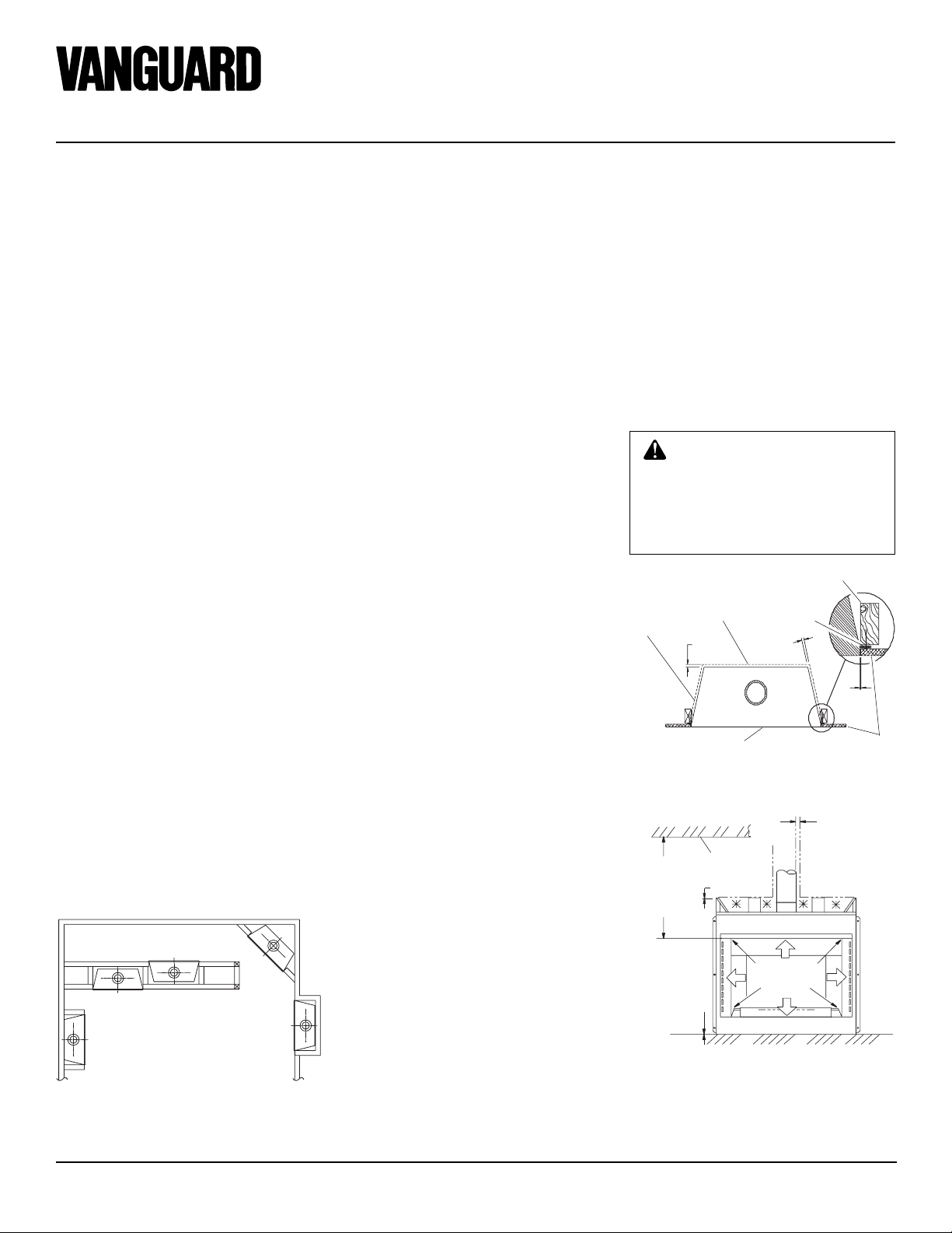
CLEARANCES
Minimum clearances to combustibles are:
• Back and Sides
of Outer Surround: ................ 1/2" min.
• Drywall to Sides of
Front Face (Nailing Flanges): ..0" min.
• "B" V ent Surfaces:....................1" min.
• Ceiling to Opening: ........... 41 1/2" min.
• Floor: ........................................0" min.
CAUTION: Do not block required air spaces with insulation or any other material. Do not
obstruct effective opening of appliance with any type of facing
material.
2 x 4 Stud
Left Side
Surround
Back
Front Face
Figure 3 - Minimum Clearances (Top View)
Ceiling
Nailing
Flange
Areas Indicated with
an “✳” are Required
Air Spaces. Do Not
Pack with Insulation
or any Other Material.
Drywall
CORNER
INTERNAL WALL
INSTALLATION
FULL
PROJECTION
INSTALLATION
INSTALLATION
FLUSH
INSTALLATION
Figure 2 - Possible Locations for Installing
Appliance
Figure 4 - Minimum Clearances (Front
View)
4
107050
OWNER’S MANUAL
41 7/8"
(1061mm)
15"
(381mm)
36
1
/4"
(921mm)
59
1
/4"
(1505mm)
29
5
/8"
(752mm)
21
3
/16"
(538mm)
CORNER INSTALLATION
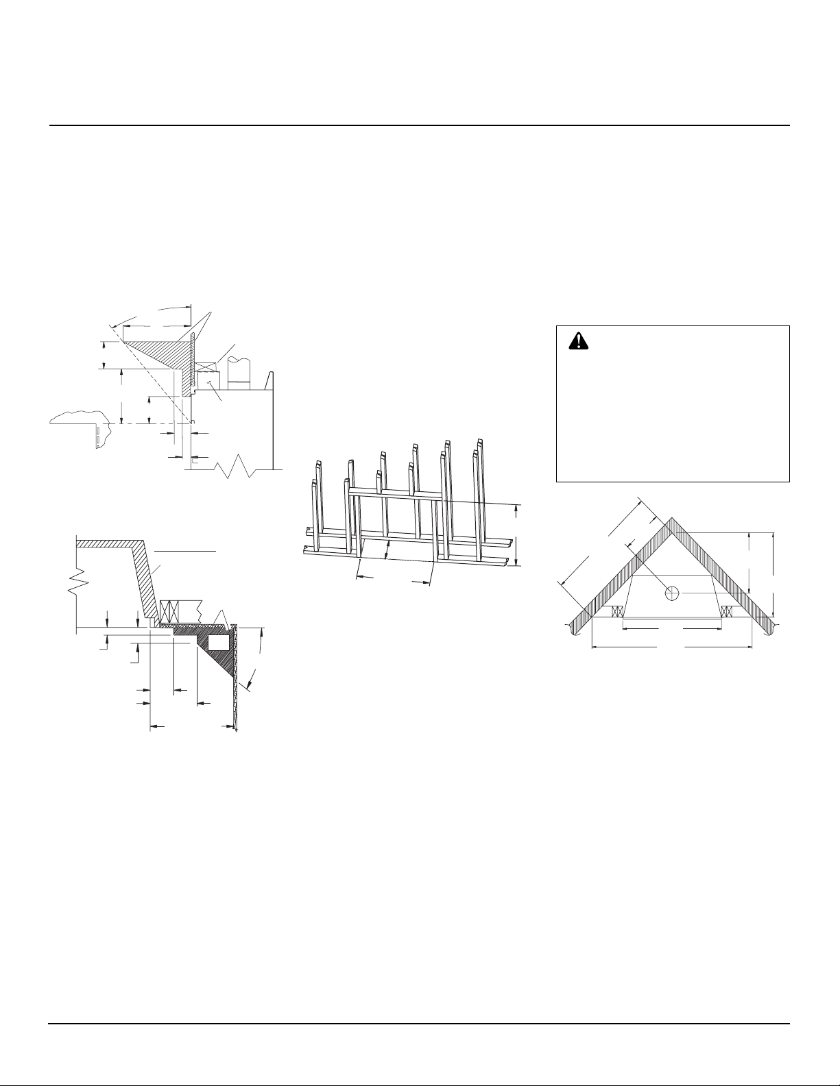
MANTEL CLEARANCES AND
WALL DETAILS
A combustible mantel shelf maybe installed a
maximum 9" (229mm) from the wall and
must have a minimum distance of 18" (457mm)
above the fireplace opening. Figures 5 and 6
show the minimum allowable distances from
various combustible mantle components in
relation to the fireplace opening.
29.5°
9"
(229mm)
6"
(152mm)
12"
(305mm)
6" Min.
(152mm)
3" (76mm)
1
/2"
1
(38mm) Max.
Figure 5 - Mantel Clearances - Side View
(Cross Section)
TOP VIEW
Outer Surround
1 1/2"
(38mm) Max.
3" (76mm) Max.
Combustible
Materials
Header
Spacer
Combustible
Material May
Be Used
Safe
Zone
33°
FRAMING
1. Frame appliance enclosure as illustrated in Figures 7 and 8.
Note:
If a wall covering is used to line
the enclosure, then all measurements
must be from the surface of the covering.
2. Place the appliance into the framing and
secure it.
Note:
If appliance is to be raised above
floor level, a platform must be built to
support the appliance.
3. Install the supply line to the appliance
using a 1/2" NPT black iron gas line terminating 2 5/16" above the bottom of the
appliance. The gas line may be installed
from either side or from the rear of the
appliance (see Figure 15, page 9).
1
/8"
38
(968mm) Min.
15 5/8" Min.
(397mm)
1
36
/4"
(921mm) Min.
Figure 7 - Rough Opening for Installing in
Wall
4. Feed flexible gas line through one of three
gas line conduit sleeve and repack insulation to cover any openings. Prepare the
incoming gas line with teflon tape or pipe
joint compound and hook-up incoming
gas line to the flexible gas line.
Note:
If 1/2" NPT black iron pipe does
not mate with fitting at the end of flexible gas line, remove fitting and replace
with a 37 degree flare 3/4"-12, 1/2" NPT
(female) fitting.
WARNING: When finishing appliance, Do not overlap combustible material onto the black front
face. Brick, tile, or other noncombustible materials may be applied
to the face provided that any gap
is between the material used and
the face is caulked with a noncombustible caulking.
6" (152mm) Min.
Within 12"
(305mm)
18" (457mm)
Min.
Figure 6 - Side Clearances - Top View
(Cross Section)
107050
Figure 8 - Rough Opening for Corner
Installation
5
EVGL850N
®
VENTED TYPE DECORATIVE APPLIANCE
VENTING
INSTALLATION
A B-type venting system must be connected
to the appliance for venting to the outside of
the building.
The following section is provided as a guide
to a standard B-type vent installation.
Standing codes requirements concerning Btype vent installations may vary within your
state, province or local codes jurisdiction.
Therefore, it is recommended that you check
with your local building codes for specific
requirements or in absence of local codes,
follow Section 7.0 of the current National
Fuel Gas Code NFPA No. 54/ANS Z223.1
and in Canada with CAN/CGA B149 for
Category I systems using double wall B-1
vent pipe.
This gas appliance must be vertically vented
to the outdoors only and may not be terminated into an attic space or into a chimney
flue servicing a solid-fuel burning appliance.
This appliance may be vented through a
manufactured chimney system or a masonry
chimney using a B-vent adapter or a chimney liner system if all are listed, inspected
and approved by local codes and/or building
authorities.
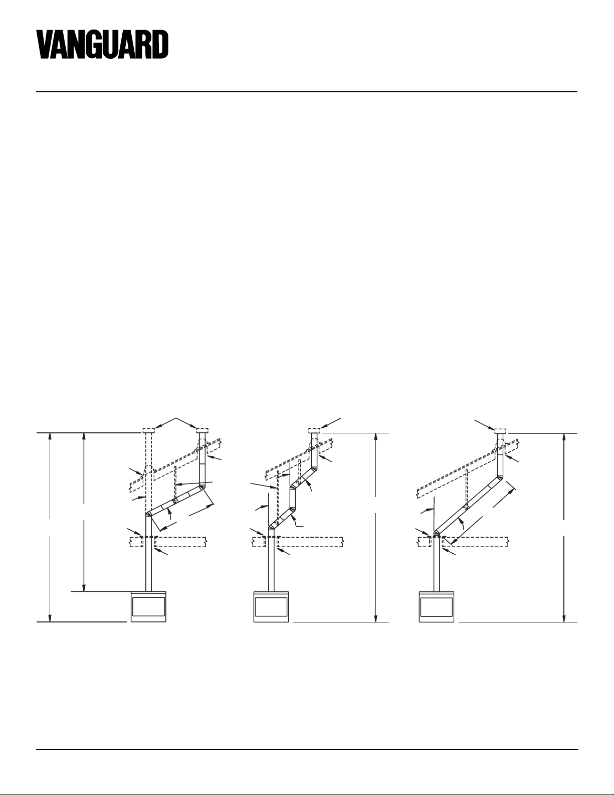
The examples shown in Figure 9 are typical
of most B-vent installations and codes practices.
Example 1:
Shows the minimum allowable
system height and lateral offset for a 60°
degree or greater inclination. Code specifies
that offsets at 60° degrees or greater are
considered horizontal and must follow the
75% percent rule for lateral to total vertical
system height. Codes also allows only one
offset in the total system when at 60° degrees or greater. The total vertical height in
this example represents the minimum height
of 8 feet and therefore the allowable lateral
is 6 feet when the 75% percent rule applies.
If the lateral length must exceed 75% then
the system must be sized in accordance with
the Category I venting tables.
Example 2:
Shows a multiple offset each
at 45° degrees of inclination. Multiple offsets are permitted if they do not exceed 60°
degrees of inclination. The total lengths of
the two offsets are not required to meet the
75% percent allowable rule.
Example 3:
Shows a single offset at 45°
degrees of inclination and therefore the
lateral length at 10 feet of offset does not
have to meet the 75% percent rule.
In each case the offsets must be supported
and firestops must be positioned wherever
the vent must pass through a sub-floor,
ceiling joist or an attic overhang. The vent
pipe must terminate vertically into a listed
type vent cap and extend a sufficient height
through an approved roof flashing, roof
jack or a roof thimble. At all points the listed
clearances must be maintained.
Listed
Vent Cap
Maintain
Listed
Clearance
60°
8'
12' Min.
Figure 9 - Typical B-Vent Configuration
Position
Firestop
6'
Maintain
Listed
Clearance
Maintain
Listed
Clearance
Support Each
Lateral At
Least Every
Six (6) Feet
Position
Firestop
45°
45°
Maintain
Listed
Clearance
Listed
Vent Cap
Maintain
Listed
Clearance
12' Min.
Position
Firestop
Listed
Vent Cap
45°
10'
Maintain
Listed
Clearance
EXAMPLE 3EXAMPLE 2EXAMPLE 1
Maintain
Listed
Clearance
12' Min.
6
107050
OWNER’S MANUAL
VENTING
INSTALLATION
Continued
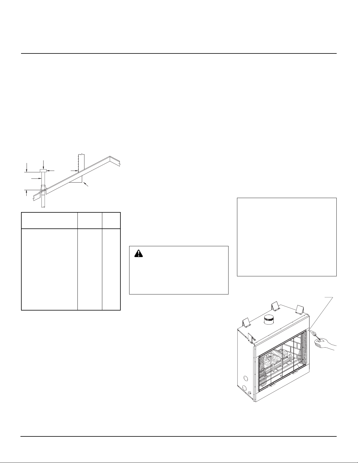
Vent terminations must be located in accordance with height and proximity rules of
NFPA No. 54 or CAN/CGA B149. These
rules apply to vents at 12 in. diameter or less
and require a minimum height in accordance with the roof pitch and a minimum of
8 ft. distance from a vertical wall or obstruction (see Figure 10).
Lowest
Discharge
Opening
H (Min)
Height
From Roof
Listed
Vent Cap
Listed Gas
Vent
8 Ft. Min.
12
x
Roof Pitch x/12
Listed Clearance
H (Min.)
Roof Pitch Ft. m
Flat to 6/12 1.0 0.30
6/12 to 7/12 1.25 0.38
Over 7/12 to 8/12 1.5 0.46
Over 8/12 to 9/12 2.0 0.61
Over 9/12 to 10/12 2.5 0.76
Over 10/12 to 11/12 3.25 0.99
Over 11/12 to 12/12 4.0 1.22
Over 12/12 to 14/12 5.0 1.52
Over 14/12 to 16/12 6.0 1.83
Over 16/12 to 18/12 7.0 2.13
Over 18/12 to 20/12 7.5 2.27
Over 20/12 to 21/12 8.0 2.44
If venting horizontally through a side wall
becomes necessary, a listed thimble approved for use with B-type vent must be
used. Check with your local codes before
venting through a side wall.
Some codes areas allow the use of existing
B-type vent systems if the system is at or
above the recommended diameter of the
flue; in this case 5".
The flue connection must be made using
listed B-type connectors and the existing
system must be code inspected for damage
and proper installation.
It is not recommended that this appliance be
common vented with an existing gas burning appliance. However, if it becomes necessary to common vent this appliance, the
venting system must be sized and configured in accordance with the common venting guides Appendix G of the current Na-
tional Fuel Gas Code NFPA No. 54/ANS
Z223.1 and in Canada with CAN/CGA B149.
Note:
Before connecting this appliance to
an existing vent system or a common venting system consult with your local architect,
planner, or building official.
WARNING: This appliance
must be properly connected to a
B-Vent system and must not be
connected to a chimney flue servicing a separate solid fuel burning appliance.
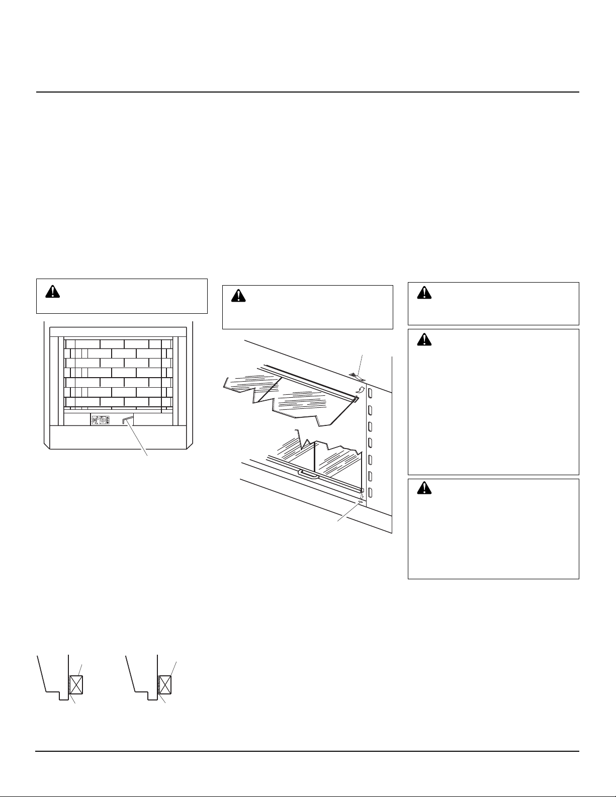
CHECKING FOR PROPER
VENTING
After completing and checking the electrical,
gas and vent connections, follow the lighting
instructions and allow the main burner to run
for approximately 5 minutes. Hold a lighted
match or cigarette near the top edge of the
window frame and play it along the entire
length of the window (see Figure 11). Proper
venting should tend to draw the flame or
smoke into the appliance. Improper venting
or escaping of spillage of burned gas, is
indicated when the match flickers or goes
out. Smoke from a cigarette will also tend to
disperse away from the appliance.
If the appliance is found to be improperly
venting, shut it off and notify your installer
or a qualified service agency to inspect the
venting system.
NOTICE: This appliance is
equipped with a vent safety
shutoff switch which will shut
down the appliance in the case of
a venting problem. Do not bypass the vent safety switch. If the
appliance should shut down, contact a qualified installer, service
agency, or your gas supplier to
have the vent inspected before
operating.
Check this area along the entire top edge
of the glass frame. Smoke or flame should
be drawn into the appliance opening.
Figure 10 - B-Vent Terminations
107050
Figure 11 - Checking for Spillage
7
EVGL850N
®
VENTED TYPE DECORATIVE APPLIANCE
INSTALLATION
WALL SWITCH
INSTALLATION (EVGL850N)
The installation of a wall switch allows you
to activate the gas control valve and turn the
fireplace on and off. The wall switch is to be
connected to the incoming 120 volt regular
household wiring that supplies the electricity to the fireplace. Refer to wiring diagram
in this manual on page 14.
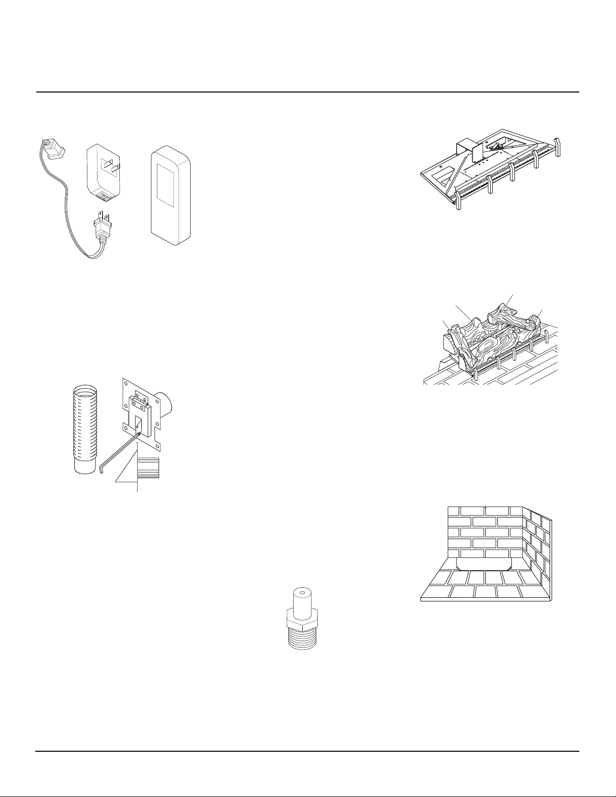
OPTIONAL REMOTE
CONTROL INSTALLATION
(Model WRC)
Note:
If using optional wireless hand-held
remote control, the wall switch must be in
the ON position to be operational. The remote control then becomes the switching
mechanism for fireplace operation.
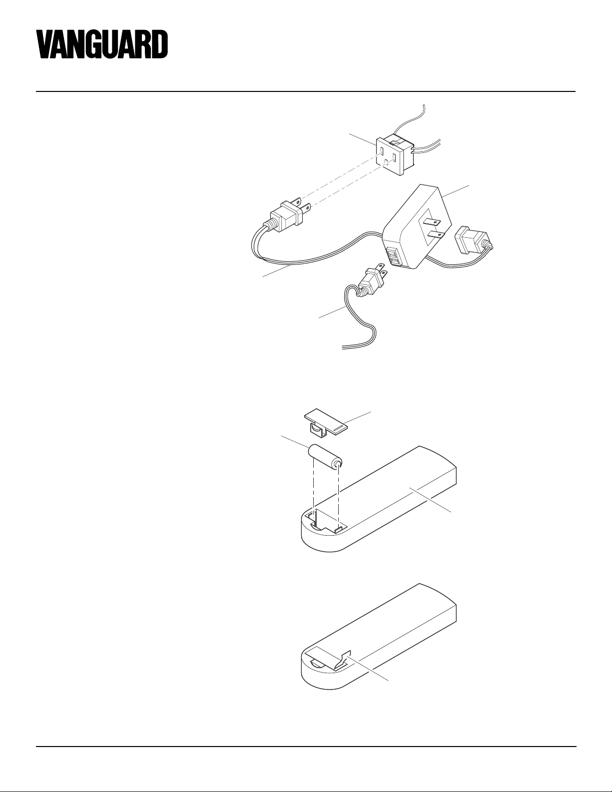
1. The WRC model receiver does not re-
quire a battery. The receiver can be installed by first plugging the short extension cord into the fireplace receptacle. Then plug the receiver unit into
the extension cord. Finally plug the ignition module plug into the receiver unit
(see Figure 12).
2. Activate the remote handset battery by
removing the insulating tab on the back
of the handset (see Figure 13). The battery is included pre-installed.
3. Once the battery is activated the unit is
ready to use.
Fireplace
Receptacle
Remote Control
Receiver
Extension Cord
Ignition Module Plug
Figure 12 - Installing the WRC Remote Receiver
Battery Cover
12 Volt Battery
Back of Handset
Pull to Remove
Insulation Tab
Figure 13 - Installing Battery into Back of Handset
8
107050

OWNER’S MANUAL
INSTALLATION
Continued
GAS LINE HOOK-UP
WARNING: Gas line hookup
should be done by your gas supplier or a qualified service person.
WARNING: Before you proceed, make sure your gas supply
is OFF.
An equipment shutoff valve has been included in the appliance’s gas supply system.
You may consider installing an extra gas
shutoff valve outside the appliance’s enclosure (check with local codes) where it can be
accessed more conveniently with a key
through a wall as shown in Figure 14.
In conformance with local codes, route a 1/2”
NPT gas line towards the appliance coming
in from any of the 3 directions shown in
Figure 15.
Typical Exterior Wall Gas
Shutoff Installation
Equipment
Shutoff Valve
CAUTION: Do not kink flex-
ible gas line.
DESA recommends that a black iron gas
line be routed from the gas source, through
a sediment trap (shown in Figure 16), and
into the appliance, Once connected through
the appliance, a flexible gas line may be
used for ease of installation to gas control
valve (see Figure 17).
Before connecting the black iron gas line to the
inside of the appliance a sediment trap must be
included outside the appliance between the
gas line and the equipment shutoff valve. It
must extend down three (3) inches beyond the
center of the pipe. Prepare incoming black
iron gas line with teflon tape or pipe joint
compound (Check with local building codes).
Incoming 1/2" Gas Line
Permitted by Local Codes
3" Min.
(76mm)
Side Wall
Of Appliance
CAUTION: Compounds used
on threaded joints of gas piping
shall be resistant to the action of
Liquefied Petroleum (LP or propane), and should be applied
lightly to ensure excess sealant
does not enter the gas line.
WARNING: All gas piping
and connections must be tested
for leaks after the installation is
completed.
After ensuring that the gas valve
is on, apply a soap and water
solution to all connections and
joints. If bubbles appear, leaks
can be detected and corrected.
Do not use an open flame for leak
testing and do not operate any
appliance if a leak is detected.
Complete your gas installation by connecting incoming gas line with flexible gas line.
Secure tightly with wrench but Do NOT
Overtighten.
Key
Extension
Figure 14 - Equipment Shutoff Valve
Installation
5
4
/8"
(117mm)
Flexible Gas Line (1 Provided) Can Be
Extended Out from 3 Sides
Figure 15 - Routing Incoming Gas Line
11"
(279mm)
1/2" NPT Incoming
Black Iron Gas
Line
5
5
/8"
(143mm)
Sediment Trap
(Not Supplied)
Figure 16 - Sediment Trap
Outlet
Pressure
Tap
Red Surface Indicates
For Propane/LP Use Only
Figure 17 - Connecting Flexible Gas Line to Electronic Valve
Inlet
Pressure
Tap
Flexible Gas Line
Do NOT Kink
Note:
1) Wire Connections
Not Shown for Clarity
2) * 1/8" NPT Plugged
Tapping
Equipment
Shutoff
Valve
1/2" NPT
Incoming
Gas Line
Continued
107050
9

EVGL850N
4
3
®
VENTED TYPE DECORATIVE APPLIANCE
INSTALLATION
Continued
GAS BURNER SUPPLY
HOOK-UP
1. Disconnect the burner form the burner
mounting flange by removing two
screws (see Figure 18).
2. Disconnect the pilot from the burner by
removing three screws holding the pilot mounting bracket (see Figure 18).
3. Rotate the back of the burner forward
and lift out of the firebox.
not damage pilot and gas line.
4. Remove the bottom refractory by lifting and sliding out the front (see Figure 19).
the flex line connector.
5. Remove the hearth pan with controls
intact by removing two screws at either side of the pan.
6. Follow steps 1,2,3,4, and 5 in reverse
order to reinstall burner assembly.
Note:
Do not kink or damage
Note:
Do
LOG & EMBER PLACEMENT
1. Center the rear log on the support
bracket welded to the back of the
burner. Press the log down onto the
bracket (see Figure 20).
2. Align the groove cut into the bottom of
the front log over the metal strip on the
burner. Make sure the metal strip is
completely in the groove. Also make
sure the notches in the bottom of the
log align over the burner holes as shown
in Figure 21.
3. Place the straight, left log piece into the
notches on the left side of the front and
rear logs (see Figure 22).
4. Place the “T”-shaped, right log piece
into the notches on the right side of the
front and rear logs (see Figure 23).
Rear Log
Burner Bracket
1
Next remove the ember material from the
bag and flatten small amounts into pieces
about the size of a dime. Place the pieces
loosely onto the exposed section of the
burner ember tray, which is located on the
very front of the burner grate. This will
create the glowing appearance as the flame
touches the ember material. Do not block
burner ports by using too much ember material in one area. Sprinkle a small amount of
vermiculite provided in the separate bag
over the embers to complete the effect. It is
not necessary to use all of the ember or
vermiculite materials provided.
To enhance the look of the hearth you may
optionally place the lava rock provided around
the front and sides of the burner. When finished replace the glass door, see Glass Door
Removal and Replacement on page 11.
NOTICE: Do not put lava rock on
burner or under burner. Placing
lava rock on burner could cause
performance problems.
Pilot Attaching
Burner Mounting
Screws (2)
Figure 18 - Removing Burner Assembly
Figure 19 - Removing Bottom Refractory
Screws (3)
1. Remove
Front of
Burner
2. Lift Refractory Over
Front Edge of Burner
Mounting Pan and
Remove from Firebox
Figure 20 - Installing Rear Log
Front Log
Notches
Metal Alignment
Strip
2
Figure 21 - Installing Front Log
Left Log
Piece
Notches
Figure 22 - Installing Left Log Piece
Right Log
Piece
Notches
Ember
Material
10
Figure 23 - Installing Right Log Piece
107050
OWNER’S MANUAL
INSTALLATION
Continued
COMBUSTION AIR KIT
MODEL AKGL (OPTIONAL)
The outside air kit may be installed on the
right side of the fireplace only. The vent can
be installed through the outside wall or a
ventilated crawl space. The handle to operate the damper door for the outside air inlet
will be located behind the burner valve
access door when the kit is installed (see
Figure 24). Pull the handle to open or push
to close.
CAUTION: Air inlet ducts are
not to terminate in attic space.
Air Kit Handle
Figure 24 - Air Kit Handle Location
APPLIANCE ENCLOSURE
Before finishing the enclosure around the
appliance, inspect all joints around the outer
surround. Any gaps between the nailing
flanges and the framing should be sealed with
noncombustible insulation or caulking.
If the appliance is mounted on a raised
platform, it must be a continuous surface
and not on blocks without a solid surface.
This will prevent the entry of cold air by
means of conduction through the total bottom of the appliance. (see Figure 25).
Side
Framing
Caulk Here
Figure 25 - Sealing Between Appliance
and Framing
Side
Framing
Pack Insulation
GLASS DOOR REMOVAL
AND REPLACEMENT
To remove, hold the glass door firmly at
handles and evenly push straight up until
bottom pins are free from location slots
(see Figure 26). Slightly swing door towards you. At this point, while maintaining glass door secured at one handle, grasp
the side of glass panel for better grip and
slightly pull glass door down to free top
pins from spring clips.
Note:
Glass door may be heavy for some
individuals. If this is the case, please request
help from someone else.
CAUTION: For use with glass
doors certified with the appliance
only.
Spring Clip
Locating Slot
Figure 26 - Removing Glass Door
To replace, insert top door pins into spring
clips located on the top face. Make sure pins
are properly secured to the clips. As you
hold top portion in place, swing bottom of
door towards bottom face until the bottom
door pins clear the flange and then insert the
lower pins into the locating slots until seated
(see Figure 26).
Note:
some adjustment maybe required in
order to align door pins to clip (top) and
locating slots (bottom).
This can be done by loosening the screw
securing both spring clip and pivot plate and
sliding it to the proper location.
Instructions for the installation of the gas kit
are included with the glass door package.
Use of any other glass door assembly not
tested with the EVGL850N model may constitute a fire hazard and will void the DESA
International warranty. Please read and follow the maintenance instructions for your
glass doors as outlined below.
• Never use an abrasive material to clean
the glass. Use a rag and a liquid cleaner.
• Never clean the glass while they are hot.
• Always operate the appliance with the
glass door in place. (If the glass is left
off the unit while operating hot combustion gas may enter the room)
CAUTION: Do not operate
the appliance with the glass door
removed.
WARNING: Installation and
repair should be done by a qualified service person. The appliance
should be inspected before each
use and at least annually by a qualified service person. More frequent
cleaning may be required due to
excessive lint from carpeting, bedding material, pet hair, etc. It is
imperative that the control compartments, burners, and circulating air system be kept clean.
WARNING: Children and
adults should be alerted to the
hazards of high surface temperatures and should stay away to
avoid burns or clothing ignition.
Young children should be supervised when they are in the same
room as the appliance.
• When ordering replacement or accessory
items please have your appliance’s model
name or number and the part number of
the item (s) you are ordering ready. The
model name or number for your particular appliance may be found on the rating
plate located inside the appliance.
• Refer to Replacement Parts, page 17
when ordering replacement parts for
your appliance.
• Repair parts or accessory items may be
bought from your local representative.
• All product specifications are subject to
change without notice.
107050
11

EVGL850N
®
VENTED TYPE DECORATIVE APPLIANCE
OPERATING
FIREPLACE
FOR YOUR SAFETY
READ BEFORE
LIGHTING
WARNING: If you do not follow these instructions exactly, a
fire or explosion may result causing property damage, personal
injury or loss of life.
A. This appliance is equipped with an
ignition device which automatically
lights the pilot. Do not try to light the
pilot by hand.
B. BEFORE LIGHTING smell all
around the appliance area for gas. Be
sure to smell next to the floor because
some gas is heavier than air and will
settle on the floor.
WHAT TO DO IF YOU SMELL
GAS
• Do not try to light any appliance.
• Do not touch any electric switch.
• Do not use any phone in your
building.
• Immediately call y our gas supplier
from a neighbor’s phone. Follow
the gas supplier’s instructions.
• If you cannot reach your gas supplier, call the fire department.
C. Do not use this appliance if any part
has been under water. Immediately
call a qualified service technician to
inspect the appliance and to replace
any part of the control system and
any gas control which has been under water.
LIGHTING
INSTRUCTIONS
1. STOP! Read the safety information,
column 1.
2. Turn off all electric power to the
appliance.
3. Turn wall switch to the OFF position.
4. Remove the glass door.
5. Open control access panel.
6. Turn the equipment shutoff valve
clockwise
tion (see Figure 27). Do not force.
7. Wait five (5) minutes to clear out any
gas. Then smell for gas, including
near the floor . I f y ou smell gas, ST OP!
Follow “B” in the safety information,
column 1. If you don’t smell gas, go to
the next step.
8. Turn the equipment shutoff valve
counterclockwise
position. Do not force.
9. Close control access panel.
10. Replace the glass door.
11. Turn on all electric power to the appliance.
12. Turn the wall switch to the ON position.
13. Visually locate the pilot. The ignitor
should begin to spark and the main
burner should ignite once flame appears at pilot.
• If lighting the appliance for the
first time each season, it may take
several attempts before the suppl y
gas can reach the pilot and main
burners.
• If the appliance will not stay lit af-
ter several attempts, follow the instructions To Turn Off Gas To Ap-
pliance, column 3, and call your
service technician or gas supplier.
to the OFF posi-
Clockwise
C-clockwise
to the ON
TO TURN OFF GAS
TO APPLIANCE
1. Turn off the wall switch.
2. Tur n off all electric power to the appliance if service is to be performed.
3. Remove the glass door.
4. Open control access panel.
5. Tur n equipment shutoff valve clockwise
6. Close control access panel.
7. Replace the glass door.
to “OFF”. Do not force.
Clockwise
OPTIONAL REMOTE
OPERATION
Note:
The WRC receiver and hand-held
remote control kit must be purchased separately (see Accessories, page 17). Follow
installation instructions on page 8.
1. Tur n equipment shutoff valve to ON
position. You can now turn the
burner on and off with the hand-held
remote control unit.
IMPORTANT:
ON/OFF buttons on the hand-held
remote control unit for up to 3 seconds to assure proper operation.
2. Press the ON/OFF button to turn the
burner on and off.
Pilot
Assembly
Figure 28 - Pilot
Be sure to press the
Ignitor/Sensor
Equipment Shutoff Valve
Control Valve
Figure 27 - Turning the Equipment Shutoff
Valve to the OFF position
12
107050

OWNER’S MANUAL
PILOT ASSEMBLY
ADJUSTMENT
Turn the adjustment screw marked pilot
clockwise to decrease or counterclockwise
to increase the flame to proper size (see
Figure 29).
Do not remove the adjustment screw.
3/8" Min.
Figure 29 - Correct Pilot Flame Pattern
Thermopile
Pilot Burner
BURNER FLAME
ADJUSTMENT
The main burner flame should be a blue flame
somewhere between a long blue flame and a
short, sharp flame that tends to blow off the
ports. If flame is short, very sharp or blowing,
the burner air shutter should be closed enough
to obtain a long blue flame (see Figure 30).
Long yellow flame produce excess carbon
monoxide and could cause sooting.
TO SHUT OFF
1. For temporary shutoff, turn off electrical power to unit either by wall switch
or remote control.
2. For long term shutoff, depress the gas
valve cock valve, located under the firebox, turn clockwise to the OFF position.
OPERATING
GUIDELINES AND
MAINTENANCE
INSTRUCTIONS
1. Upon completing your gas line connection, a small amount of air will be in
the lines. When first lighting the appliance it will take the appliance a few
minutes to purge the air . Once pur ging
is complete, the pilot and burner will
light and operate as indicated in the
instruction manual. Subsequent lighting of the appliance will not require
such purging.
1. When lit for the first time, the appliance will emit a slight odor for an hour
or two. This is due to the “curing” of
the logs and “burn-in” of internal paints
and lubricants used in the manufacturing process.
2. Keep control compartment, logs burners, and area surrounding the logs
clean by vacuuming or brushing at
least twice a year. Do not vacuum the
mineral wool located in the front of
the burner assembly.
3. Always turn off gas to pilot before
cleaning. For example relighting, refer
to the lighting instructions.
4. A qualified field service technician should
inspect the appliance and venting system
before use or at least annually.
WARNING: The logs can be
hot. Handle only when cool.
MAINTENANCE
WARNING: Turn off gas and
electrical power before servicing
appliance. It is recommended that
a qualified serviceman perform
these checkups at the beginning
of each heating season.
In order to properly clean the burner and
pilot assembly remove the logs exposing the
burner and pilot assembly.
CLEANING BURNER AND
PILOT
Clean all foreign materials from the top of
burner and from bottom panel below. Check
to make sure that burner orifice is clean.
Visually inspect pilot. Brush or blow away
any dust and lint accumulations. If pilot
orifice is plugged, disassembly maybe required to remove any foreign materials from
orifice and/or tubing. When appliance is put
back in service, check pilot flame patterns
(see Figure 29).
CORRECT
Long, Blue Flame
INCORRECT
CLOSE
SHUTTER
INCORRECT
OPEN
SHUTTER
Figure 30 - Burner Flame Patterns
107050
with Yellow Tips
Short, Sharp,
Blowing Flame
Long, Uneven,
Yellow Flame
5. Always keep the appliance area clear
and free from combustible materials,
gasoline and other flammable vapors
and liquids.
6. Never obstruct the flow of combustion
and ventilation air. Keep the front of
the appliance clear of all obstacles and
materials.
7. Never leave children unattended when
the appliance is operating.
13

EVGL850N
®
VENTED TYPE DECORATIVE APPLIANCE
SERVICE HINTS
When Gas Pressure Is Too Low
• pilot will not stay lit
• burner will have delayed ignition
• fireplace will not produce specified heat
• propane/LP gas supply may be low
When Gas Quality Is Bad
• pilot will not stay lit
• burner will produce flames and soot
• fireplace will backfire when lit
You may feel your gas pressure is too low or
gas quality is bad. If so, contact your local
propane/LP gas supplier.
WIRING DIAGRAM
HEAT
LIMIT
SWITCH
Pilot
Control
Valve
INCOMING
MAIN GAS
SUPPLY
EV1
EV2
GAS LINE
BURNER
Ignitor
TO
TECHNICAL
SERVICE
You may have further questions about installation, operation, or troubleshooting.
If so, contact DESA International’s Technical Service Department at 1-800-323-5190.
You can also visit DESA International’s
technical services web site at
www.desatech.com.
Connectors
(Not Supplied)
Field Wire
BLACK
WHITE
GREEN
ELECTRICAL RATING:
120v, 60Hz, 0.7A
Hearth Pan
IGN
MODEL SP745 IGNITION CONTROL
Robertshaw
PV
GND
TR
PV/MV
TH
MV
24V AC
STEP DOWN
TRANSFORMER
120V AC
WALL SWITCH
(SUPPLIED)
ON
GREEN
BLACK
WHITE
OPTIONAL
REMOTE
CONTROL
OFF
INCOMING
120V AC
(FUSE BOX
OR BREAKER)
14
107050

OWNER’S MANUAL
TROUBLESHOOTING
Note:
For additional help, visit DESA
International’s technical service web
site at www.desatech.com.
Note:
Before troubleshooting the system,
make sure the equipment shutoff valve is ON.
OBSERVED PROBLEM
Ignitor will not spark or pilot will not light
The two most common causes of a malfunctioning gas appliance are:
1. Loose wiring connections
2. Construction debris clogging the pilot and/or gas control valve filter
POSSIBLE CAUSE
1. No gas supply, or equipment shutoff
valve is OFF
2. Air in gas line
3. Construction debris clogging pilot orifice
4. Low gas pressure
5. Kinked pilot line
6. Control valve knob is not opening
7. No power to unit or the ignition module
or power transformer is bad
REMEDY
1. Check to see if you have gas supply and
that the equipment shutoff valve is
opened
2. Repeat lighting procedure several times
to purge all air out of lines. If after repeated attempts appliance does not light
call for qualified service and repair
3. Remove debris and dirt, inspect and
clean any other possible obstructions
4. Contact your gas supplier to check pressure
5. Have a qualified technician replace pilot line
6. Replace control valve (Refer to Replace-
ment Parts, page 17)
7. Check that main power is on and that all
wire connections are made correctly to
the ignition model (see Wiring Diagr am,
page 14). Check for 24 VAC at the secondary side of the transformer. If 24 V AC
is present and the module does not operate, have the module replaced otherwise have the transformer replaced
Pilot lights but will not stay lit
No gas to main burner, although wall switch
and valve are set to the ON position
Frequent main burner outage
107050
1. Loose wiring on ignitor wire to ignition
module and/or poor ground to ignition
module
2. Pilot flame too low to sense
1. Wall switch wires defective or too long
2. Sensor, valve, or ignition module is not
operating
1. Pilot flame may be too low, causing
safety pilot to “drop out”
2. Vent may be blocked or restricted
www.desatech.com
15
1. Check ignitor wire connection. Refer to
wiring diagram (see Wiring Diagram,
page 14) and/or check ground wire to
ignition module
2. Clean and adjust pilot burner and check
gas supply and inlet pressure to unit
Note:
Have a qualified technician replace
pilot assembly if broken or corroded
1. Check electrical connections
2. Recheck problems 1 and 2
1. Clean and adjust pilot flame for maximum
flame impingement on sensor
2. Have vent inspected for blockage or
damage
Continued

EVGL850N
®
VENTED TYPE DECORATIVE APPLIANCE
TROUBLESHOOTING
Continued
WARNING: If you smell gas
• Shut off gas supply.
• Do not try to light any appliance.
• Do not touch any electrical switch; do not use any phone in your
building.
• Immediately call your gas supplier from a neighbor’s phone. Follow the
gas supplier’s instructions.
• If you cannot reach your gas supplier, call the fire department.
IMPORTANT:
supplies, paint, paint remover, cigarette smoke, cements and glues, new carpet or textiles,
etc., create fumes. These fumes may mix with combustion air and create odors.
Operating fireplace where impurities in air exist may create odors. Cleaning
OBSERVED PROBLEM
Fireplace produces a clicking/ticking noise
just after burner is lit or shut off
Fireplace produces unwanted odors
Gas odor even when control knob is in OFF
position
Gas odor during combustion
Dark residue on logs or inside of fireplace
POSSIBLE CAUSE
1. Metal expanding while heating or contracting while cooling
1. Fireplace burning vapors from paint, hair
spray, glues, etc. (See
statement above)
2. Gas leak. See Warning statement at
top of page
1. Gas leak. See Warning statement at
top of page
2. Control valve defective
1. Foreign matter between control valve
and burner
2. Gas leak. See Warning statement at
top of page
1. Improper log placement
2. Air holes at burner inlet blocked
3. Burner flame holes blocked
IMPORTANT
REMEDY
1. This is common with most fireplaces. If
noise is excessive, contact qualified service person
1. Ventilate room. Stop using odor causing products while fireplace is running
2. Locate and correct all leaks (see Gas
Line Hook-Up, page 9)
1. Locate and correct all leaks (see Gas
Line Hook-Up, page 9)
2. Replace control valve
1. Take apart gas tubing and remove foreign matter
2. Locate and correct all leaks (see Gas
Line Hook-Up, page 9)
1. Properly locate logs (see Log & Ember
Placement, page 10)
2. Clean out air holes at burner inlets. Periodically repeat as needed
3. Remove blockage or replace burner
www.desatech.com
16
107050
OWNER’S MANUAL
ACCESSORIES
Transmitter
Receiver
RECEIVER AND HAND-HELD
REMOTE CONTROL KIT
00710 (WRC)
For all models. Allows the gas log heater to
be turned on and off by using a hand-held
remote control.
AIR KIT - 90325 (AKGL)
Optional kit helps offset the negative pressure often existing in today's tightly constructed homes.
REPLACEMENT
PARTS
Note:
Use only original replacement parts.
This will protect your warranty coverage for
parts replaced under warranty.
PARTS UNDER WARRANTY
Contact authorized dealers of this product. If
they can’t supply original replacement part(s)
call DESA International’s Technical Service Department at 1-800-323-5190 for referral information.
When calling DESA International, have
ready
• your name
• your address
• model and serial numbers of your fireplace
• how fireplace was malfunctioning
• type of gas used (propane/LP or natural
gas)
• purchase date
Usually, we will ask you to return the defective part to the factory.
PARTS NOT UNDER
WARRANTY
Contact authorized dealers of this product. If
they can’t supply original replacement part(s)
call DESA International’s Parts Department
at 1-800-972-7879 for referral information.
When calling DESA International, have
ready
• model number of your fireplace
• the replacement part number
BURNER ASSEMBLY
27109 (107223-01)
Right Log Piece
Rear Log
Left Log
Piece
Front Log
LOG SET - 14586 (105855-01)
Top Left Log - 105856-01
Top Right Log - 105857-01
Bottom Rear Log - 105858-01
Bottom Front Log - 105859-01
107050
REFRACTORY PIECES
Back - 20938 (105864-01)
Left/Right Side - 20939 (105865-01)
Bottom - 20937 (105866-01)
ORIFICE
Natural - 23099 (105862-01)
17
EVGL850N
®
VENTED TYPE DECORATIVE APPLIANCE
REPLACEMENT
PARTS
Continued
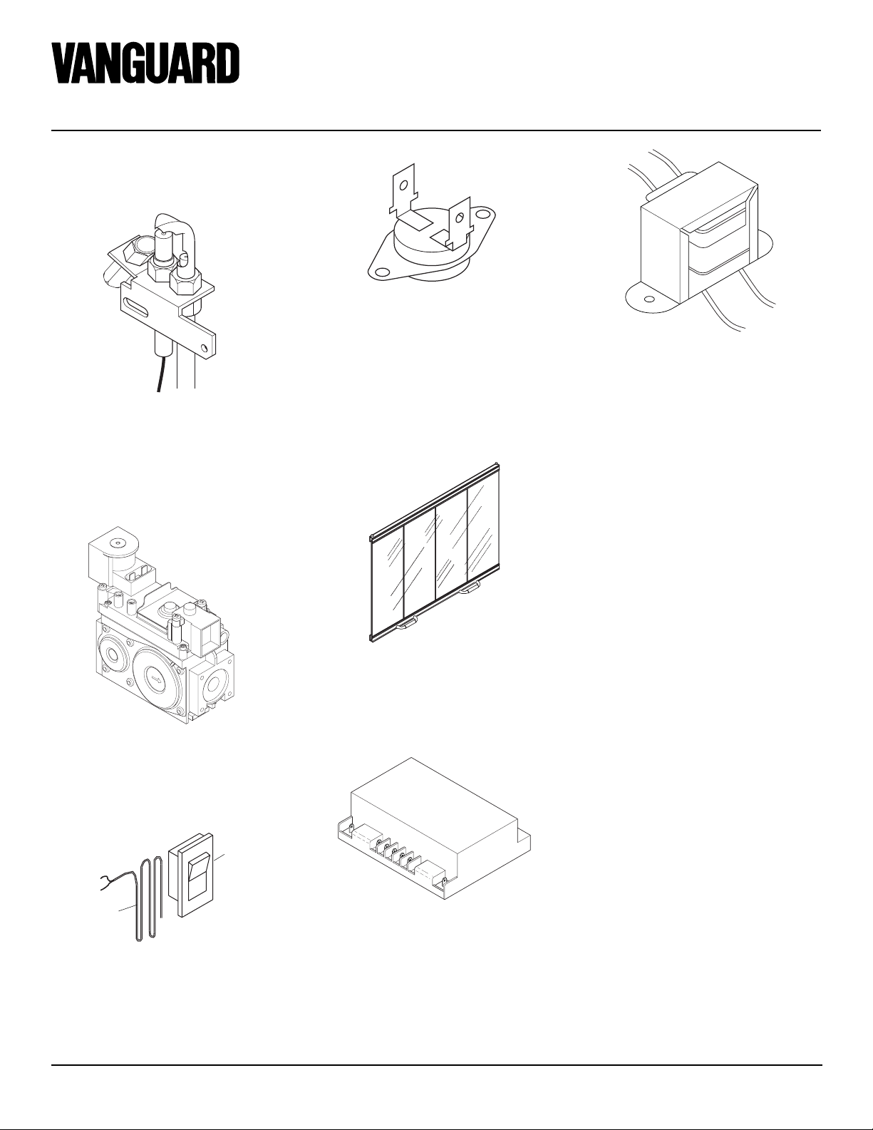
HEAT LIMIT SWITCH
14519 (105911-01)
TRANSFORMER
14129 (107222-01)
PILOT ASSEMBLY
Natural (Electronic) - 27197
(107220-01)
If in need of replacing, have a qualified
technician replace it.
Should the limit switch need replacing, have
a qualified technician replace it (see Wiring
Diagram, page 14). The limit switch is
located under the top door track on the right
hand side.
GAS CONTROL VALVE
Natural - 14569 (107219-01)
If in need of replacing, have a qualified
technician replace it.
Wall Switch
and Cover
Plate
Millivolt
Wires
WALL SWITCH
22180 (105742-01)
Wall switch, cover plate, and wires are
supplied with the appliance. If wires need
replacing, use proper gauge.
FIXED GLASS DOORS
01605 (105863-01)
IGNITION MODULE
14301 (107221-01)
18
107050

OWNER’S MANUAL
NOTES
_______________________________________________________________________________________________
_______________________________________________________________________________________________
_______________________________________________________________________________________________
_______________________________________________________________________________________________
_______________________________________________________________________________________________
_______________________________________________________________________________________________
_______________________________________________________________________________________________
_______________________________________________________________________________________________
_______________________________________________________________________________________________
_______________________________________________________________________________________________
_______________________________________________________________________________________________
_______________________________________________________________________________________________
_______________________________________________________________________________________________
_______________________________________________________________________________________________
_______________________________________________________________________________________________
_______________________________________________________________________________________________
_______________________________________________________________________________________________
_______________________________________________________________________________________________
_______________________________________________________________________________________________
_______________________________________________________________________________________________
_______________________________________________________________________________________________
_______________________________________________________________________________________________
_______________________________________________________________________________________________
_______________________________________________________________________________________________
_______________________________________________________________________________________________
_______________________________________________________________________________________________
_______________________________________________________________________________________________
_______________________________________________________________________________________________
_______________________________________________________________________________________________
_______________________________________________________________________________________________
_______________________________________________________________________________________________
_______________________________________________________________________________________________
_______________________________________________________________________________________________
_______________________________________________________________________________________________
107050
19

WARRANTY INFORMATION
KEEP THIS WARRANTY
Model
Serial No.
Date Purchased
Always specify model and serial numbers when communicating with the factory.
We reserve the right to amend these specifications at any time without notice. The only warranty applicable is our standard written
warranty. We make no other warranty, expressed or implied.
LIMITED WARRANTY
B-VENT FIREPLACE
DESA International warrants this product to be free from defects in materials and components for four (4) years from the date of first purchase,
provided that the product has been properly installed, operated and maintained in accordance with all applicable instructions. To make a claim
under this warranty the Bill of Sale or cancelled check must be presented.
This warranty is extended only to the original retail purchaser. This warranty covers the cost of part(s) required to restore this heater to proper
operating condition and an allowance for labor when provided by a DESA Authorized Service Center. Warranty part(s) MUST be obtained
through authorized dealers of this product and/or DESA International who will provide original factory replacement parts. Failure to use
original factory replacement parts voids this warranty. The heater MUST be installed by a qualified installer in accordance with all local codes
and instructions furnished with the unit.
This warranty does not apply to parts that are not in original condition because of normal wear and tear, or parts that fail or become damaged
as a result of misuse, accidents, lack of proper maintenance or defects caused by improper installation. Travel, diagnostic cost, labor,
transportation and any and all such other costs related to repairing a defective heater will be the responsibility of the owner.
TO THE FULL EXTENT ALLOWED BY THE LAW OF THE JURISDICTION THAT GOVERNS THE SALE OF THE PRODUCT;
THIS EXPRESS WARRANTY EXCLUDES ANY AND ALL OTHER EXPRESSED WARRANTIES AND LIMITS THE DURATION
OF ANY AND ALL IMPLIED WARRANTIES, INCLUDING WARRANTIES OF MERCHANTABILITY AND FITNESS FOR A
PARTICULAR PURPOSE TO FOUR (4) YEARS ON ALL COMPONENTS FROM THE DATE OF FIRST PURCHASE; AND DESA
INTERNATIONAL’S LIABILITY IS HEREBY LIMITED TO THE PURCHASE PRICE OF THE PRODUCT AND DESA INTERNATIONAL SHALL NOT BE LIABLE FOR ANY OTHER DAMAGES WHATSOEVER INCLUDING INDIRECT, INCIDENTAL OR
CONSEQUENTIAL DAMAGES.
Some states do not allow a limitation on how long an implied warranty lasts or an exclusion or limitation of incidental or consequential
damages, so the above limitation on implied warranties, or exclusion or limitation on damages may not apply to you.
This warranty gives you specific legal rights, and you may also have other rights that vary from state to state.
For information about this warranty write:
INTERNATIONAL
2701 Industrial Drive
P.O. Box 90004
Bowling Green, KY 42102-9004
www.desatech.com
107050 01
NOT A UPC
107050-01
Rev. A
02/00
 Loading...