

Denon DRA-685 Owner’s Manual
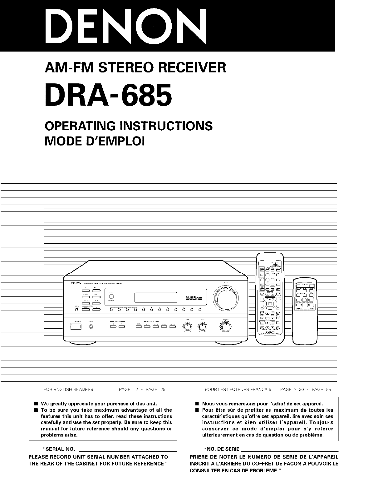
AM-FM STEREO RECEIVER
DRA-685
OPERATING INSTRUCTIONS
MODE D'EMPLOI
jr
o _ o o
FOR ENGL(SH READERS PAGE 2 o- PAGE 29
• We greatly appreciate your purchase of this unit.
• To be sure you take maximum advantage of all the
features this unit has to offer, read these instructions
carefully and use the set properly. Be sure to keep this
manual for future reference should any questions or
problems arise.
"SERIAL NO.
PLEASE RECORD UNIT SERIAL NUMBER ATTACHED TO
THE REAR OF THE CABINET FOR FUTURE REFERENCE"
0 0 0 0 0 0 0 0 0 0
Mull Room /
Z_C
oO Oo ......
POUR LES LECTEURS FRANCAIS PAGE 2, 30 PAGE 55
• Nous vous remercions pour I'achat de cet appareil.
• Pour &tre s_r de profiter au maximum de toutes les
caracteristiques qu'offre cet appareil, life avec soin ces
instructions et bien utiliser I'appareil. Toujours
conserver ce mode d'emploi pour s'y referer
ulterieurement en cas de question ou de problbme.
"NO. DE SERIE
PRIERE DE NOTER LE NUMERO DE SERIE DE L'APPAREIL
INSCRIT A L'ARRIERE DU COFFRET DE FA(_ON A POUVOIR LE
CONSULTER EN CAS DE PROBLEME."
[_e,]_.,,_ F_ _]
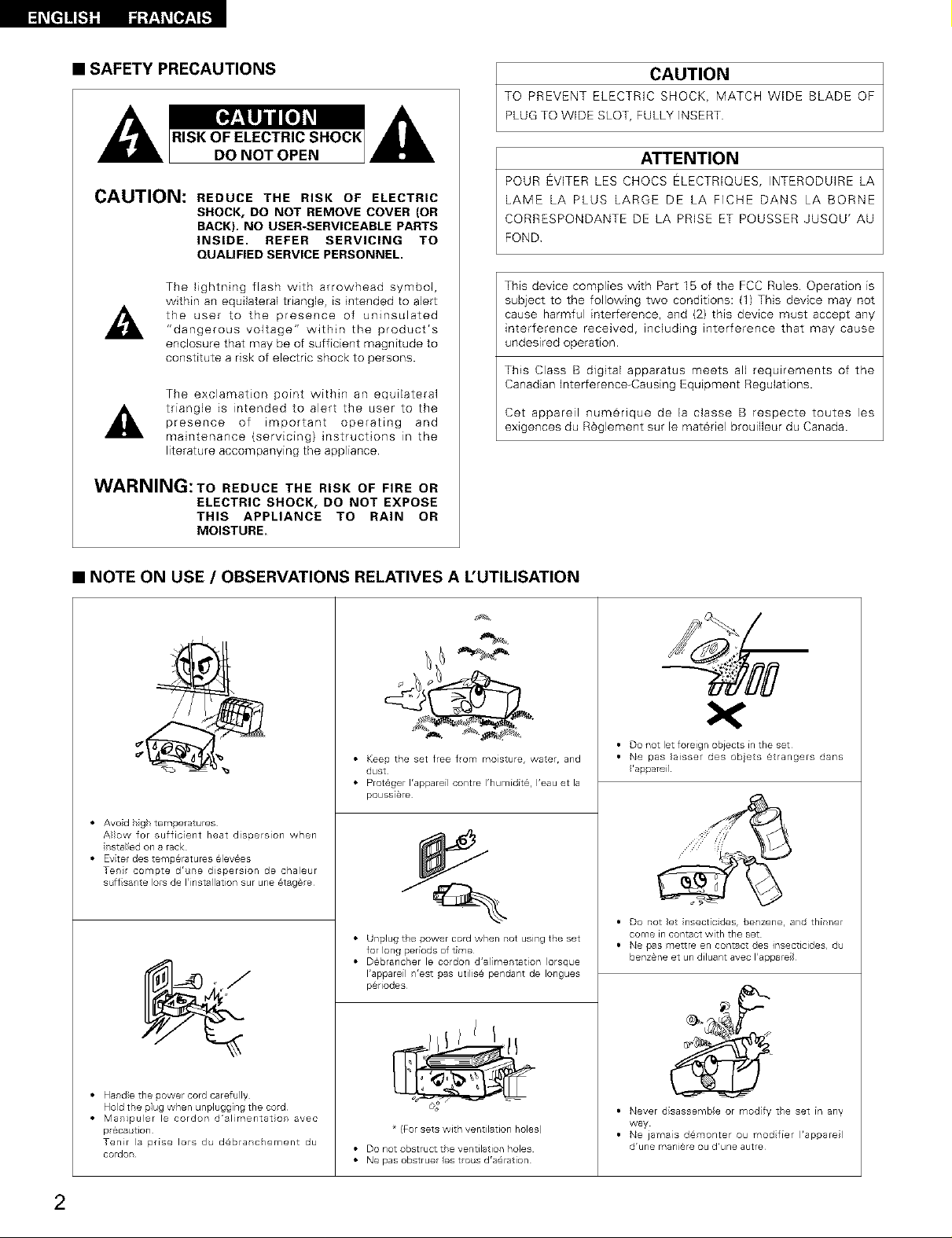
• SAFETY PRECAUTIONS
CAUTION: REDUCE THE RISK OF ELECTRIC
SHOCK, DO NOT REMOVE COVER (OR
BACK). NO USER-SERVICEABLE PARTS
INSIDE. REFER SERVICING TO
QUALIFIED SERVICE PERSONNEL.
The lightning flash with arrowhead symbol,
within an equilateral triangle, is intended to alert
the user to the presence of uninsulated
"dangerous voltage" within the product's
enclosure that may be of sufficient magnitude to
constitute a risk of electric shock to persons.
The exclamation point within an equilateral
presence of important operating and
triangle is intended to alert the user to the
maintenance (servicing) instructions in the
literature accompanying the appliance.
WARNING:To REDUCE THE RISK OF FIRE OR
ELECTRIC SHOCK, DO NOT EXPOSE
THIS APPLIANCE TO RAIN OR
MOISTURE.
CAUTION
TO PREVENT ELECTRIC SHOCK, MATCH WIDE BLADE OF
PLUG TO WIDE SLOT, FULLY INSERT
ATTENTION
POUR EVITER LES CHOCS ELECTRJQUES, INTERODUIRE LA
LAME LA PLUS LARGE DE LA FICHE DANS LA BORNE
CORRESPONDANTE DE LA PRISE ET POUSSER JUSQU' AU
FOND
This device complies with Part I5 of the FCC Rules Operation is
subject to the following two conditions: (1) This device may not
cause harmful interference, and (2) this device must accept any
interference received, including interference that may cause
undesired operation.
This Class B digital apparatus meets all requirements of the
Canadian Interference-Causing Equipment Regulations.
Cet appareil num@rique de la classe B respecte toutes les
exlgences du R_glement sur le materiel brouilleur du Canada.
• NOTE ON USE / OBSERVATIONS RELATIVES A L'UTILISATION
• Keep the set free flom moisture, water, and
dust
• Prot@ger I'appareil contre I'humidd_, I'eau et la
poussi_re
• Avo d h gh temperat=Jres
A}}ow for sufficient heat dissersion when
r stalled on a rack
• Eviter des temperatures @levees
Tent compte dr re dispersion de chaleur
s ffsarte lots de I'installation sur une 6tag_re
• Unplug the power cord when r ot using the set
for long periods of time
• D6brancler le cordon d'almentation }orsque
I'appareil r'est sas utilis@ pendant de Iongues
p@riodes
• Do not let foreign obiects in the set
• Ne pas }aissel des obets @trangers dans
'a_areil
• Do not }et nsect cides, benzene, and thinner
come in contact with the set
• Ne pas mettre en contact des insecticides, d
benzane et un diluant avec I'appare
• Hand}e the sower cord carefully
Hold the plug when unplugging the cord
• Mampuler le cordon d'al mentat or avec
pr6ca tlon
Tenir la prise Iors du d@branchement du
cordon
2
* (For sets with ventilation holes)
• Donotobstructt e ventilation holes
• Nepasobstruer estro sdra@ration
• Never disassembe or modify the set in any
way
• Ne jamas d@monter ou rood fier I'apsarel
drune mani@re ou d'une autre
SAFETY INSTRUCTIONS
1.
Read Instructions - All the safety and operating instructions
should be read before the product is operated.
2.
Retain Instructions - The safety and operating instructions
should be retained for future reference
3.
Heed Warnings - AII warnings on the product and in the
operating instructions should be adhered to
4.
Follow Instructions - All operating and use instructions should
be followed.
5.
Cleaning - Unplug this product from the wall outlet before
cleaning Do not use liquid cleaners or aerosol cleaners.
6.
Attachments - Do not use attachments not recommended by
the product manufacturer as they may cause hazards
7.
Water and Moisture - Do not use this product near water - for
example, near a bath tub, wash bowl, kitchen sink, or laundry
tub; in a wet basement; or near a swimming pool; and the like.
8.
Accessories - Do not place this product on an unstable cart,
stand, tripod, bracket, or table The product may fall, causing
serious injury to a child or adult, and serious damage to the
product. Use only with a cart, stand, tripod, bracket, or table
recommended by the manufacturer, or sold with the product.
Any mounting of the product should follow the manufacturer's
instructions, and should use a
mounting accessory
recommended by the
manufacturer.
g.
A product and cart
combination should be
moved with care Quick
stops, excessive force,
and uneven surfaces may
cause the product and cart
combination to overturn
10.
Ventilation - Slots and openings in the cabinet are provided for
ventilation and to ensure reliable operation of the product and
to protect it from overheating, and these openings must not be
blocked or covered. The openings should never be blocked by
placing the product on a bed, sofa, rug, or other similar
surface This product should not be placed in a built in
installation such as a bookcase or rack unless proper
ventilation is provided or the manufacturer's instructions have
been adhered to
11.
Power Sources - This product should be operated only from
the type of power source indicated on the marking label. If
you are not sure of the type of power supply to your home,
consult your product dealer or local power company. For
products intended to operate from battery power, or other
sources, refer to the operating instructions.
12.
Grounding or Polarization - This product may be equipped with
a polarized alternating=current line plug (a plug having one
blade wider than the other). This plug will fit into the power
outlet only one way. This is a safety feature If you are unable
to insert the plug fully into the outlet, try reversing the plug If
the plug should still fail to fit, contact your electrician to replace
your obsolete outlet Do not defeat the safety purpose of the
polarized plug
13 Power-Cord Protection - Power=supply cords should be routed
so that they are not likely to be walked on or pinched by items
placed upon or against them, paying particular attention to
cords at plugs, convenience receptacles, and the point where
they exit from the product.
15 Outdoor Antenna Grounding - If an outside antenna or cable
system is connected to the product, be sure the antenna or
cable system is grounded so as to provide some protection
against voltage surges and built=up static charges. Article 810
of the National Electrical Code, ANSI/NFPA 70, provides
information with regard to proper grounding of the mast and
supporting structure, grounding of the leaddn wire to an
antenna discharge unit, size of grounding conductors, location
of antenna=discharge unit, connection to grounding electrodes,
and requirements for the grounding electrode See Figure A.
16 Lightning - For added protection for this product during a
lightning storm, or when it is left unattended and unused for
long periods of time, unplug it from the wall outlet and
disconnect the antenna or cable system This will prevent
damage to the product due to lightning and powerqine surges
17 Power Lines- An outside antenna system should not be
located in the vicinity of overhead power lines or other electric
light or power circuits, or where it can fall into such power
lines or circuits. When installing an outside antenna system,
extreme care should be taken to keep from touching such
power lines or circuits as contact with them might be fatal.
18 Overloading - Do not overload wall outlets, extension cords, or
integral convenience receptacles as this can result in a risk of
fire or electric shock.
19
Object and Liquid Entry - Never push objects of any kind into
this product through openings as they may touch dangerous
voltage points or short=out parts that could result in a fire or
electric shock Never spill liquid of any kind on the product.
20.
Servicing - Do not attempt to service this product yourself
as opening or removing covers may expose you to
dangerous voltage or other hazards. Refer all servicing to
qualified service personnel.
21.
Damage Requiring Service - Unplug this product from the
wall outlet and refer servicing to qualified service personnel
under the following conditions:
a) When the power supply cord or plug is damaged,
b) If liquid has been spilled, or objects have fallen into the
product,
c) If the product has been exposed to rain or water,
d) If the product does not operate normally by following the
operating instructions Adjust only those controls that are
covered by the operating instructions as an improper
adjustment of other controls may result in damage and will
often require extensive work by a qualified technician to
restore the product to its normal operation,
e) If the product has been dropped or damaged in any way,
and
f) When the product exhibits a distinct change in performance
- this indicates a need for service.
22 Replacement Parts - When replacement parts are required, be
sure the service technician has used replacement parts
specified by the manufacturer or have the same characteristics
as the original part Unauthorized substitutions may result in
fire, electric shock, or other hazards
23 Safety Check - Upon completion of any service or repairs to
this product, ask the service technician to perform safety
checks to determine that the product is in proper operating
condition.
24 Wall or Ceiling Mounting - The product should be mounted to
a wall or ceiling only as recommended by the manufacturer.
25 Heat - The product should be situated away from heat sources
such as radiators, heat registers, stoves, or other products
(including amplifiers) that produce heat
NEC NATIONAL ELECTR_CA_ CODE
(NEC ART 25O PART H]
3
_t]]E-t]][
• INTRODUCTION
Thank you for choosing the DENON AM-FM Stereo receiver. This remarkable component has been engineered to provide outstanding high
fidelity reproduction of your favorite music sources.
As this product is provided with an immense array of features, we recommend that before you begin hookup and operation that you review the
contents of this manual before proceeding
TABLE OF CONTENTS
Before Using .................................................................. 4
Cautions on Installation ...................................................... 5
Cautions on Handling ......................................................... 5
Features ........................................................................ 5
Connections ............................................................... 6-10
Part Names and Functions .......................................... 10, 11
Remote Control Unit ................................................... 12-17
• ACCESSORIES
Check that the following parts are included in addition to the main unit:
(1) Operating instructions ...................................................
(2) Warranty .....................................................................
(3) Service station lisl .........................................................
(4) Remote control unit (RC_872) ..........................................
(RC-873) ..........................................
(RC-872) (RC-873)
Operations ............................................................... 17-23
Listening to the Radio ................................................ 24-26
El Initialization of the Microprocessor .................................... 27
Last function memory ...................................................... 27
Troubleshooting ............................................................ 28
El Specifications ............................................................... 29
(5} Batteries (R6P/AA) ......................................................... 2
(R03/AAA) ...................................................... 2
(6} AM loop antenna ......................................................... 1
(7} FM indoor antenna ......................................................... 1
® ® ®
[] BEFORE USING
Pay attention to the following before using this unit:
• Moving the set
To prevent short circuits or damaged wires in the connection
cords, always unplug the power cord and disconnect the
connection cords between all other audio components when
moving the set.
• Before turning the power operation switch on
Check once again that all connections are proper and that there are
not problems with the connection cords. Always set the power
operation switch to the standby position before connecting and
disconnecting connection cords.
• Store this instructions in a safe place.
After reading, store this instructions along with the warranty in a
safe place
• Note that the illustrations in this instructions may differ from
the actual set for explanation purposes.
4
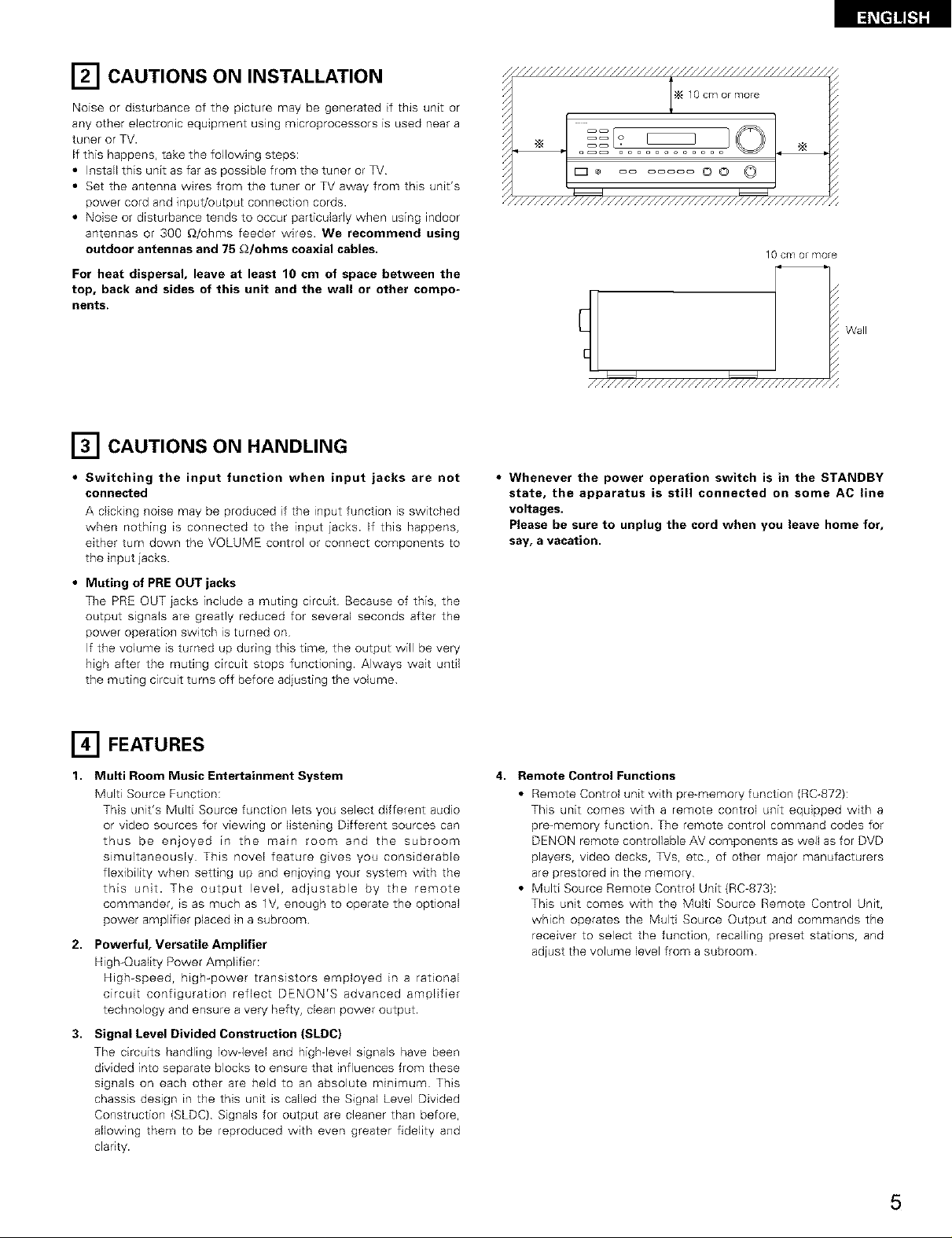
[] CAUTIONS ON INSTALLATION
Noise or disturbance of the picture may be generated if this unit or
any other electronic equipment using microprocessors is used near a
tuner or TV.
If this happens, take the following steps:
• Install this unit as far as possible from the tuner or TV
• Set the antenna wires from the tuner or TV away from this unit's
power cord and input/output connection cords.
• Noise or disturbance tends to occur particularly when using indoor
antennas or 300 £_/ohms feeder wires. We recommend using
outdoor antennas and 75 £_/ohms coaxial cables.
For heat dispersal, leave at least 10 cm of space between the
top, back and sides of this unit and the wall or other compo-
nents.
[] CAUTIONS ON HANDLING
///////////////////////////////////////////////,,
N 10cm or more
* ....... OO © [
"//////////////////////////////////////////////,
10 Cm or more
Wall
////////////////////////////////////
• Switching the input function when input jacks are not
connected
A clickhTg noise may be produced if the input function is switched
when nothing is connected to the input jacks. If this happens,
either turn down the VOLUME control or connect components to
the input jacks.
• Muting of PRE OUT jacks
The PRE OUT iacks include a muting circuit Because of this, the
output signals are greatly reduced for several seconds after the
power operation switch is turned on
If the volume is turned up during this time, the output will be very
high after the muting circuit stops functioning. Always wait until
the muting circuit turns off before adjusting the volume
[] FEATURES
1. Multi Room Music Entertainment System
Multi Source Function:
This unit's Multi Source function lets you select different audio
or video sources for viewing or listening Different sources can
thus be enjoyed in the main room and the subroom
simultaneously This novel feature gives you considerable
flexibility when setting up and enjoying your system with the
this unit. The output level, adjustable by the remote
commander, is as much as lV, enough to operate the optional
power amplifier placed in a subroom
2,
Powerful, Versatile Amplifier
High-Quality Power Amplifier:
High-speed, high-power transistors employed in a rational
circuit configuration reflect DENON'S advanced amplifier
technology and ensure a very hefty, dean power output.
3. Signal Level Divided Construction (SLDC)
The circuits handling low level and highqevel signals have been
divided into separate blocks to ensure that influences from these
signals on each other are held to an absolute minimum This
chassis design in the this unit is called the Signal Level Divided
Construction (SLDC) Signals for output are cleaner than before,
allowing them to be reproduced with even greater fidelity and
clarity.
• Whenever the power operation switch is in the STANDBY
state, the apparatus is still connected on some AC line
voltages.
Please be sure to unplug the cord when you leave home for,
say, a vacation.
4. Remote Control Functions
• Remote Control unit with pre-memory function (RC_872):
This unit comes with a remote control unit equipped with a
pro-memory function. The remote control command codes for
DENON remote controllable AV components as well as for DVD
players, video decks, TVs, etc, of other major manufacturers
are prestored in the memory
• Multi Source Remote Control Unit (RC=873):
This unit comes with the Multi Source Remote Control Unit,
which operates the Multi Source Output and commands the
receiver to select the function, recalling preset stations, and
adjust the volume level from a subroom
5
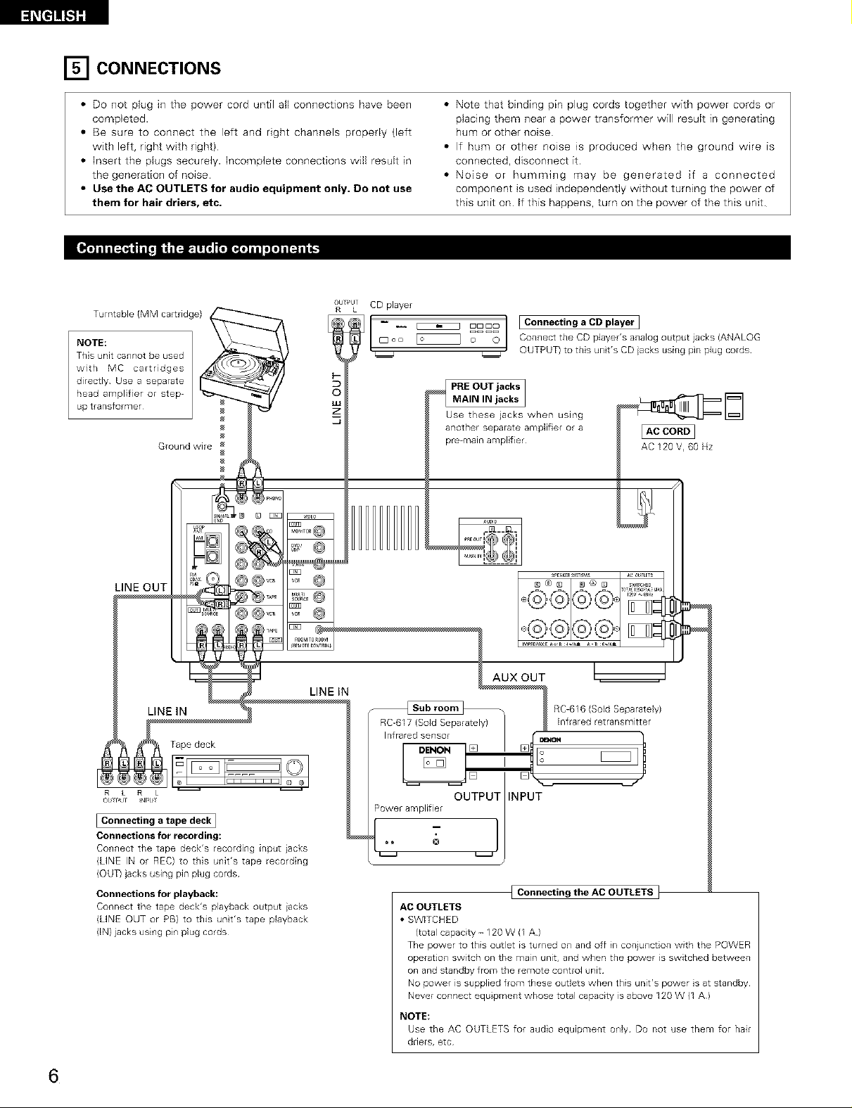
[] CONNECTIONS
• Do not plug in the power cord until aft connections have been
completed.
• Be sure to connect the left and right channels propedy (left
with left, right with right)
• Insert the plugs securely. Incomplete connections will result in
the generation of noise
• Use the AC OUTLETS for audio equipment only. Do not use
them for hair driers, etc.
OL >JT CD player
L
_oo _o °°
©
Ground wire
• Note that binding pin plug cords together with power cords or
placing them near a power transformer will result in generating
hum or other noise
• If hum or other no4se is produced when the ground wire is
connected, disconnect it
• Noise or humming may be generated if a connected
component is used independently without turning the power of
this unit on If this happens, turn on the power of the this unit.
I Connecting a CD player I
Connect the CD player's analog output jacks (ANALOG
OUTPUT) to this unit's CD iacks using pin plug cords¸
Use these jacks when using
another separate amplifier or a
pre-maln ampl fief
AC 120 V, 60 Hz
LINE OUT i
LiNE IN
Tape deck
[ Connecting a tape deck ]
Connections for recording:
Co_wlect the tape deck's recording input iacks
(LINE IN or REC) to this u_fit's tape recording
(OUT) jacks using pin plug cords
Connections for playback:
Connect the tape deck's playback output iacks
(LINE OUT or PB) to this unt's tape playback
(IN) jacks using pin plug cords
LINE iN
AUX OUT
RC-616 (Sold Separately)
RC-617 (Sold Separately)
Infrared sensor
DENON
[]
OUTPUT INPUT
Power amplifier
Infrared retransmitter
- l
AC OUTLETS
• SWITCHED
(total capacity - 120 W (1 A)
The power to this outlet is turned on and off in conjunction with the POWER
operation switch on the main unit, and when the power is switched between
on and otandby from the remote control unit¸
No power is supplied from these outlets when this unit's power is at standby¸
Never connect equipment whose total capacity is above 120 W (1 A)
NOTE:
Use the AC OUTLETS for audio equipment only Do not use them for hair
driers, etc
[ Connecting the AC OUTLETS }
6
• To connect the video signal, connect using a 75 _/ohms video signal cable cord Using an improper cable can result in a drop in sound quality
• When making connections, also refer to the operating instructions of the other components
[_i_e]]![.l][
TV or DBS tuner
k OdT
o VIDEa 1]
5
©
©
5
©
©
I Connecting a TV/DBS tuner
TV/DBS
• Connect the TV's or DBS tuner's video output iack
(VDEO OUTPUT) to the _ (yellow) VAUX IN jack
using a 75 _Z/uhms video coaxial pin plug cord
• Connect the TV's or DBS tuner's audio output jacks
(AUDIO OUTPUT) to the _ VAUX IN jacks using
pin plug cords
LD player (VDP) or DVD player
L OU
.... _Z
I Connecting a video disc player VDP or a DVD player I
• Connect the video disc player's (DVD player's) video output jack (VIDEO OUTPUT) to
the _ (yellow) DVD/VDP IN jack using a 75 £_/ohms video coaxial pin plug cord
• Connect the video disc player's (DVD player's) analog audio output iacks (ANALOG
AUDIO OUTPUT) to the _ DVD/VDP IN jacks using pn plug cords
MONITOR OUT
• Connect the TV's video input jack (VDEO
INPUT) to the _ MONITOR OUT jack
using a 75 _/uhms video coaxial pin plug
cord
Monitor _V
_J
VIDEO OUT
VIDEO IN
Connecting a video decks ]
Video input/output connections:
• Connect the video deck's video output jack (VIDEO OUT) to the
(yellow} VCR IN jack, and the video deck's video input jack
(VIDEO IN) to the _ (yellow) VCR OUT jack using 75 _/ohms
video coaxial pin plug cords
Connecting the audio output jacks
• Connect the video deck audio output jacks (AUDIO OUT) to the
VCR IN jacks, and the video deck's audio input iacks (AUDIO
IN) to the _ VCR OUT jacks using pin plug cords¸
7
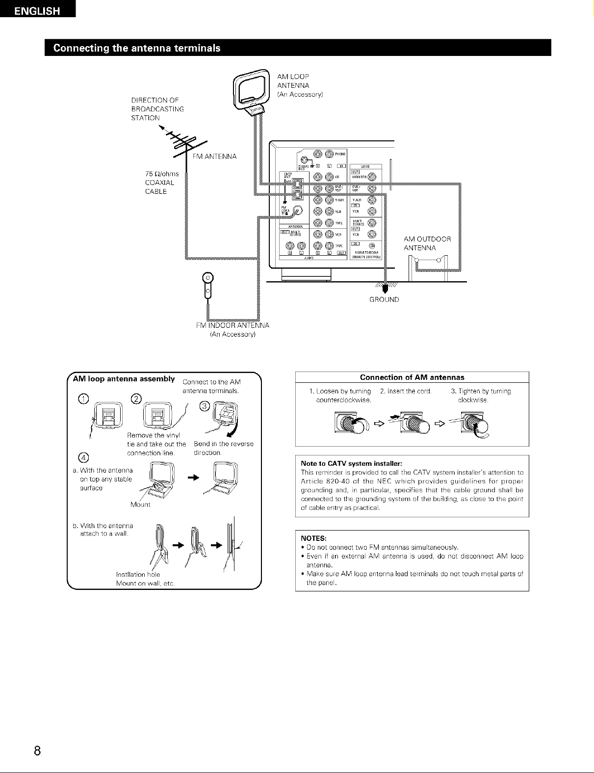
DIRECTION OF
BROADCASTING
STATION
ANTENNA
AM LOOP
(An Accesso W)
/ FM ANTENNA
75_ohms
COAXIAL
CABLE
FM INDOOR ANTENNA
(An Accesso W)
fANI loop antenna assembly Connect to the AM
a rite n1_8 terminals
©
Remove the vinyl
tie and take out the Bend in the reverse
(_ connection line direction
a With the antenna
on top any stabJe '_
suFrace
Mount
_?@ .....
_, @@ o .........@
,_S_D'_D_aVD
@ @..... _,o_@
0,,..... @@, ............
@@1@@,,_, _ ®
_LUO0 R_4_T_C_NR_ i
GROUND
Connection of AM antennas
1 Loosen by turning 2 Inset tee cord 3 Tighten by turning
counterclockwise clockwise
Note to CATV system installer:
This reminder is provided to call the CAT\! system installer's attention to
Art cle 82040 of the NEC which provides guidelines for proper
grounding and, in particular, specifies that the cable ground snail be
connected to the ground ng system of the building, as close to the point
of cable entry as practical
AM OUTDOOR
ANTENNA
///_ ////
NOTES:
b Wtt_{{_t/Iteantwe_nlna _ _1_ _1_ _L_
Insdlation hole
Mount on wall, etc
J
• DO not connect two FM antennas simLfltaneously
• Even if an external AM antenna is used, do not disconnect AM loop
antenna
• Make sure AM loop antenna lead terminaB do not touch metal parts of
the panel
8
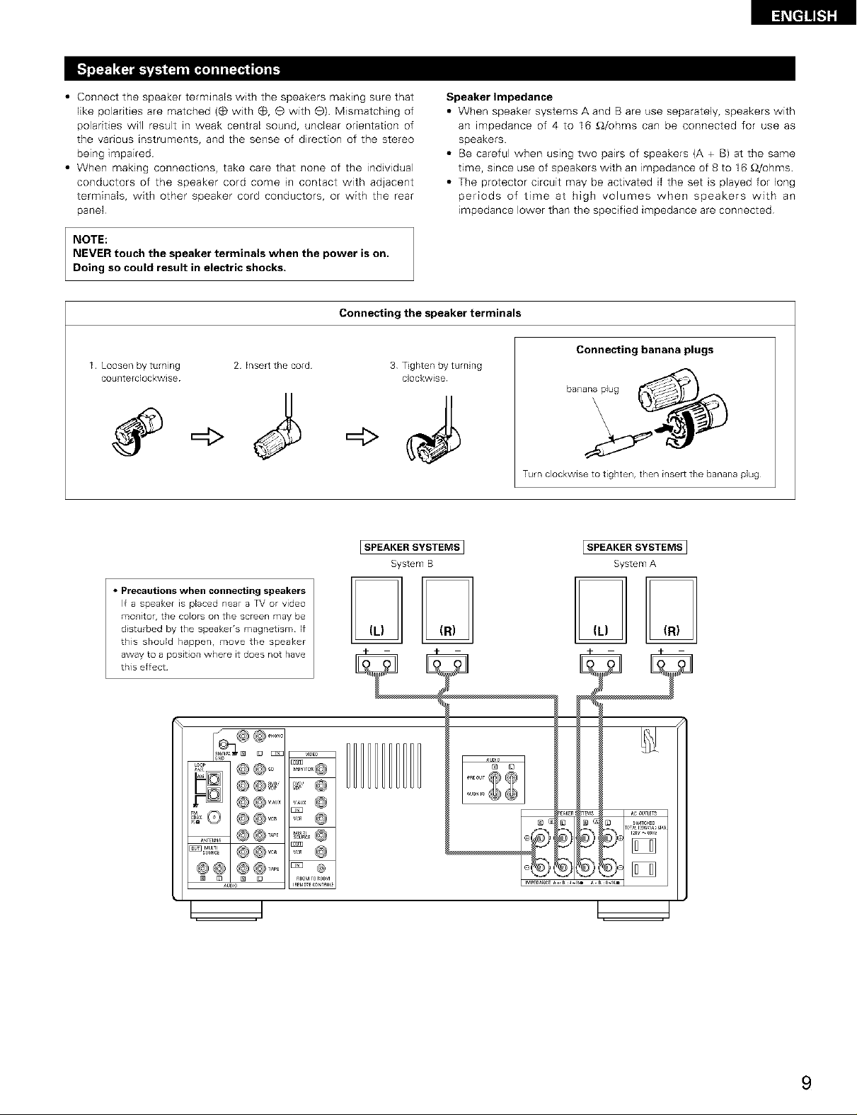
• Connect the speaker terminals with the speakers making sure that
like polarities are matched (_ with (_, e with e) Mismatching of
polarities will result in weak central sound, unclear orientation of
the vanous instruments, and the sense of direction of the stereo
being impaired
• When making connections, take care that none of the individual
conductors of the speaker cord come in contact with adjacent
terminals, with other speaker cord conductors, or with the rear
panel
NOTE:
NEVER touch the speaker terminals when the power is on.
Doing so could result in electric shocks.
Connecting the speaker terminals
1 Loosen by turning 2 Insert the cord
counterdockwise
3 Tighten by turning
=4>
Speaker Impedance
• When speaker systems A and B are use separately, speakers with
an impedance of 4 to I6 £_/ohms can be connected for use as
speakers
• Be careful when using two pairs of speakers {A + B) at the same
time, since use of speakers with an impedance of 8 to 16 £_/ohms
• The protector circuit may be activated if the set is played for long
periods of time at high volumes when speakers with an
impedance lower than the specified impedance are connected
Connecting banana plugs
clockwise
bananaplug
Turn clockwise to tighten, then insert the banana plug
• Precautions when connecting speakers
If a speaker is placed near a TV or video
monitor, the Colors on the screen may be
disturbed by the speaker's magnetism¸ If
this should happen, move the speaker
away to a position where it does not have
this effect¸
[SPEAKER SYSTEMS1 ISPEAKERSYSTEMS ]
System B System A
m m
9
• This unit is equipped with a high-speed protection circuit. This circuit protects the internal circuitry from damage due to
large currents flowing if the speaker jacks are not completely connected or if an output is generated by a short circuit.
In such a case, the protection circuit will operate to cut off the output to the speakers. Should this happen, turn the
power off and check the speaker connections. Then turn the power on again. After muting for several seconds, the
receiver should be operating normally.
If the protection circuit is activated again even though there are no problems with the wiring or the ventilation around
the unit, switch off the power and contact a DENON service center.
• The protector circuit may be activated if the set is played for long periods of time at high volumes when speakers with
an impedance lower than the specified impedance (for example speakers with an impedance of lower than 4 £)/ohms)
are connected. If the protector circuit is activated, the speaker output is cut off. Turn off the set's power, wait for the set
to cool down, improve the ventilation around the set, then turn the power back on.
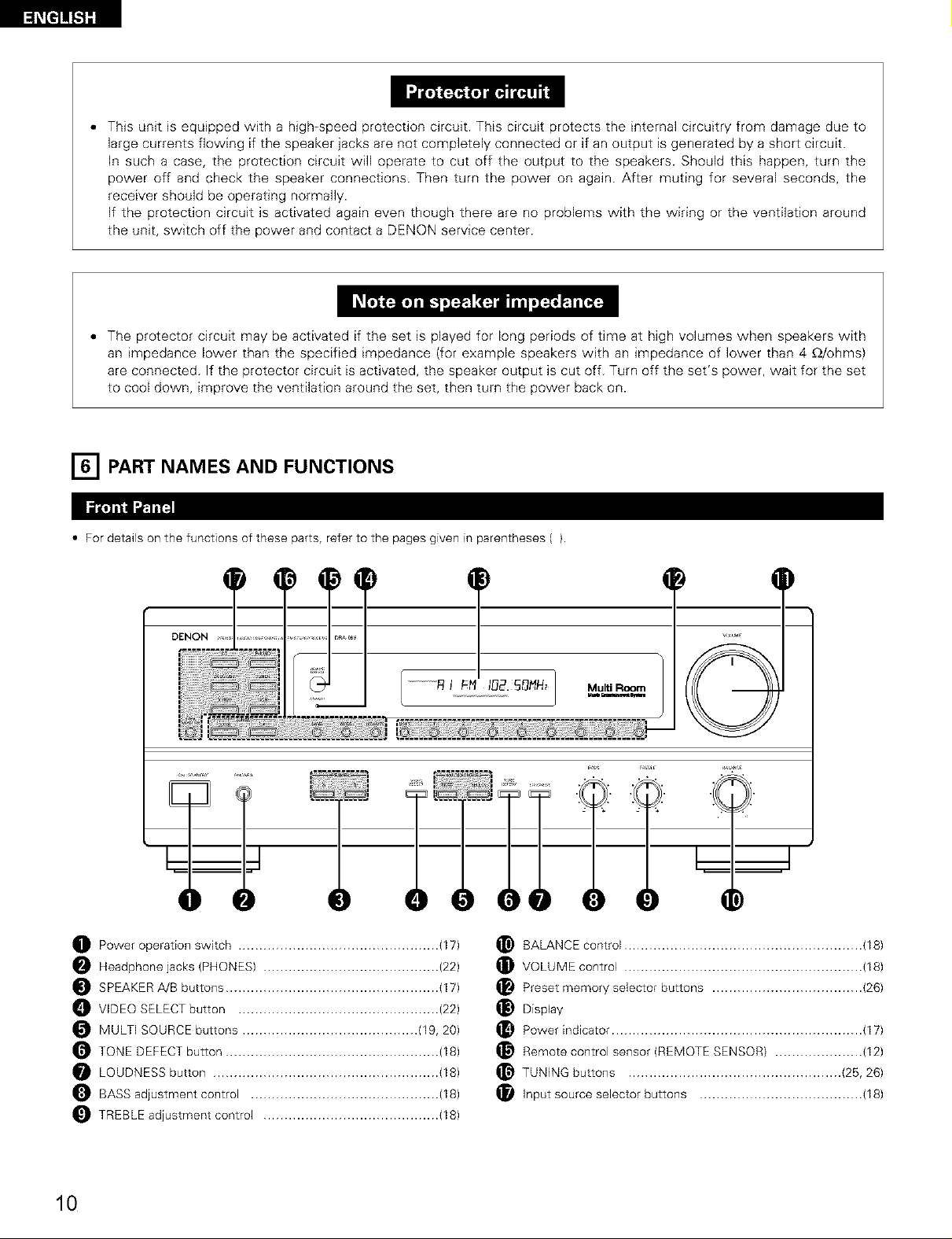
[] PART NAMES AND FUNCTIONS
• For details on the functions of these parts, refer to the pages given in parentheses ().
)
................._ I _-_ I_2._NN_ Multi Room
......................................,.9. _. O._..O._..O. @. O. O. @
O Power operation switch ................................................ (17)
Headphone jacks (PHONES) .......................................... (22)
SPEAKER A/B buttons ................................................... (17)
VIDEO SELECT button ................................................ (22)
MULTI SOURCE buttons .......................................... (19, 20)
TONE DEFECT button ................................................... (18)
LOUDNESS button ...................................................... (18)
BASS adjustment control ............................................. (18)
TREBLE adjustment control .......................................... (18)
T
O
BALANCE control ......................................................... (18)
VOLUME control ......................................................... (18)
Preset memory selector buttons .................................... (26)
Display
Power indicator ............................................................ (17)
Remote control sensor (REMOTE SENSOR) ..................... (12)
TUNING buttons ................................................... (25, 26)
Input source selector buttons ....................................... (18)
10
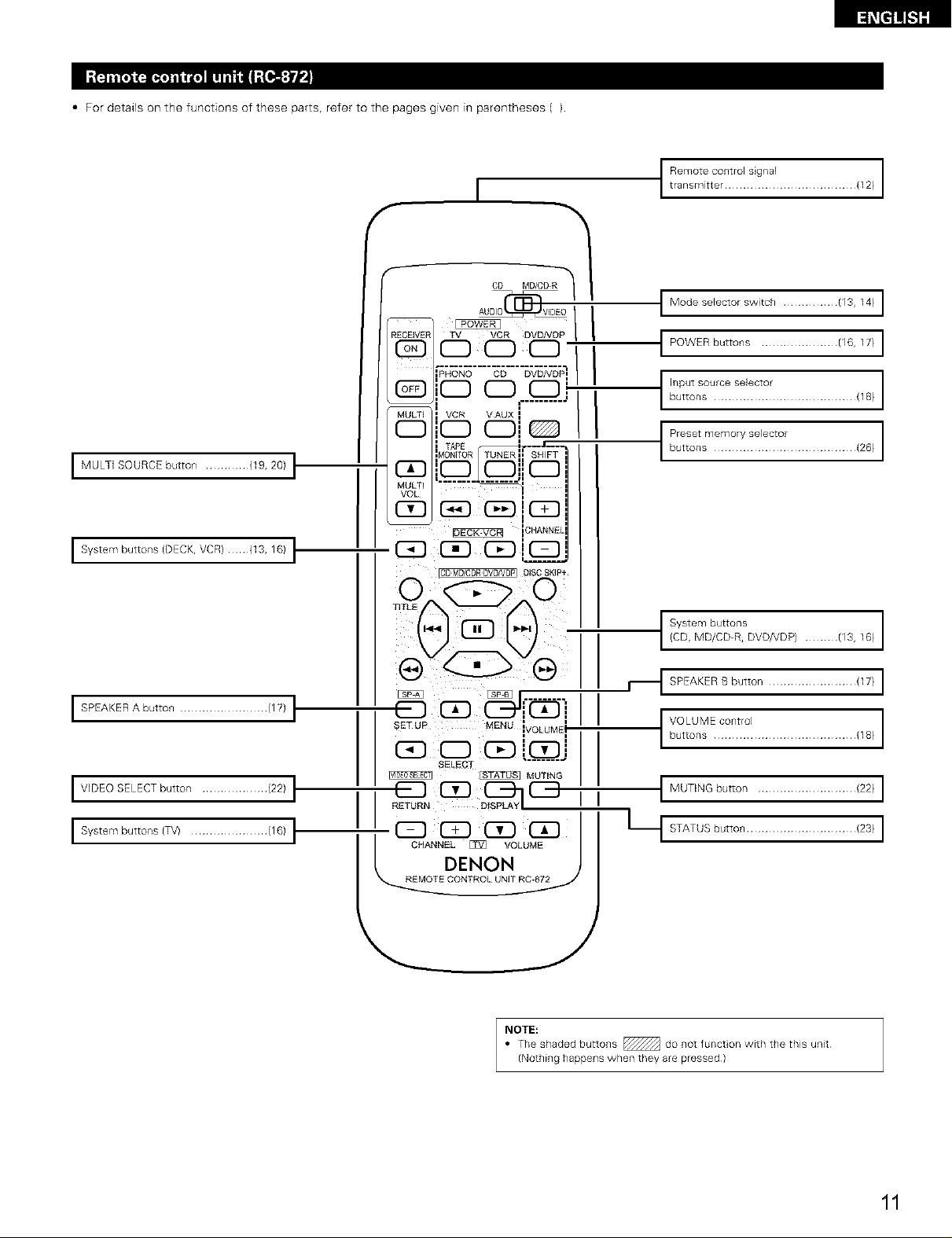
• For details on the functions of these parts, refer to the pages given in parentheses ().
I MULTI SOURCE button ............ {19, 20) t
[_[t]_t]][
t tRrenms_itt_O:_rO[ : gr:a[ ...................... (12)
I Modese[ector switch ............... (13, 14) I
t POWER buttons ..................... (16,17} I
C:nS:Ttttt'tt11:.......................,18,
_::t::mtT?::?'it:t:...................(28_
I System buttons (DECK, VCR) {13, 16) I"
I SPEAKER A button ........................ (17) I
I VIDEO SELECT button .................. (22) I
I System buttons (TV) ..................... (16) I"
t/_4%?C;;-%VO.DP/........./13,18/
,_1SPEAKERBbutton........................117/I
tVu°ttL°:'?E?::K............................,18/
I MUTING button ........................... {22) I
Lt STATUS button .............................. {23) I
NOTE:
• The shaded buttons _ do not funct on with the this unit
(Nothing happens when they are pressed)
11
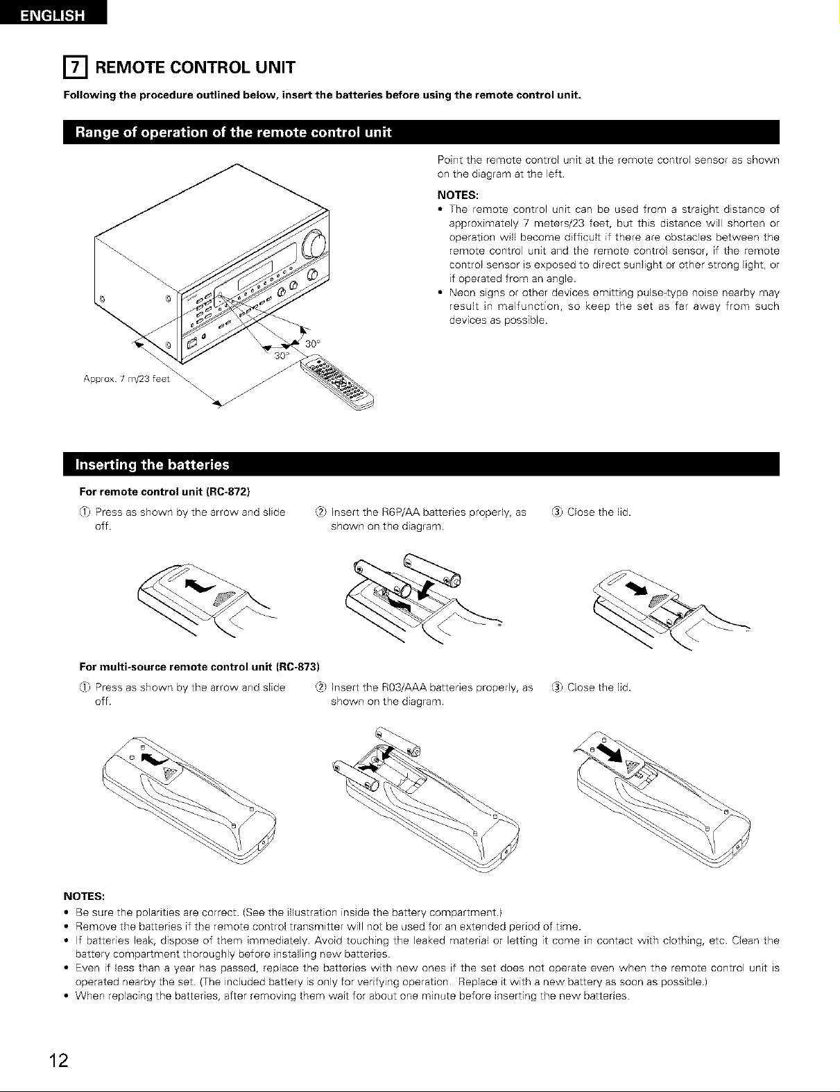
[] REMOTE CONTROL
Following the procedure outlined below, insert the batteries before using the remote control unit.
Approx 7 m/23 feet
UNIT
Point the remote control unit at the remote control sensor as shown
on the diagram at the left
NOTES:
• The remote control unit can be used from a straight distance of
approximately 7 meters/23 feet, but this distance will shorten or
operation will become difficult if there are obstacles between the
remote control unit and the remote control sensor, if the remote
control sensor is exposed to direct sunlight or other strong light, or
if operated from an angle.
• Neon signs or other devices emitting pulse-type noise nearby may
result in malfunction, so keep the set as far away from such
devices as possible.
For remote control unit (RC-872}
0_) Press as shown by the arrow and slide
off.
For multi-source remote control unit (RC-873)
0_) Press as shown by the arrow and slide (2) Insert the R03/AAA batteries properly, as
off. shown on the diagram.
,:.2_Insert the R6P/AA batteries properly, as
shown on the diagram.
_3)Close the lid.
_3)Close the lid.
NOTES:
• Be sure the polarities are correct. (See the illustration inside the battery compartment)
• Remove the batteries if the remote control transmitter will not be used for an extended period of time.
• If batteries leak, dispose of them immediately. Avoid touching the leaked material or letting it come in contact with clothing, etc Clean the
battery compartment thoroughly before installing new batteries
• Even if less than a year has passed, replace the batteries with new ones if the set does not operate even when the remote control unit ts
operated nearby the set (The included battery is only for verifying operation Replace it with a new battery as soon as possible)
• When replacing the batteries, after removing them wait for about one minute before inserting the new batteries
12
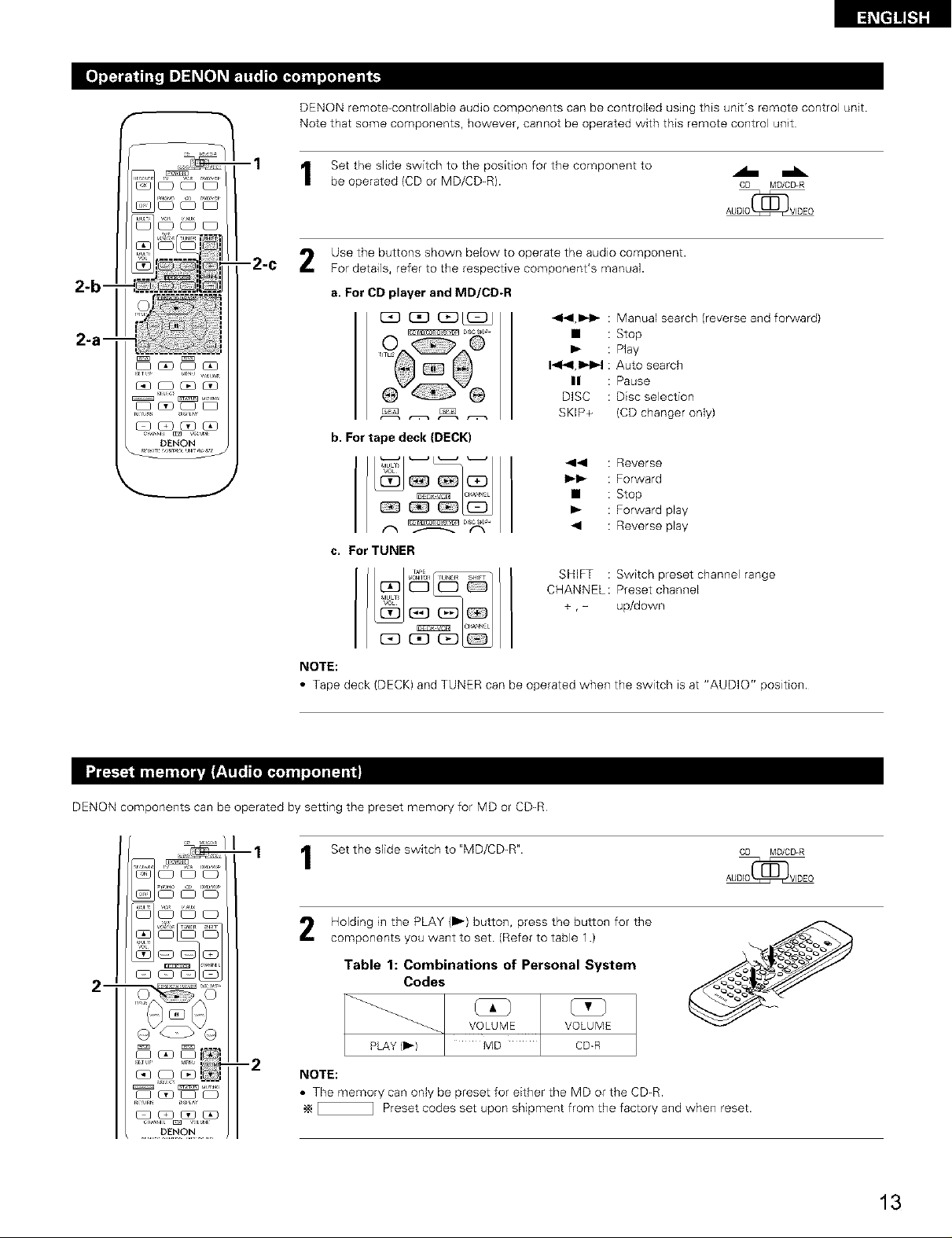
DENON remote_controllable audio components can be controlled using this unit's remote control unit.
Note that some components, however, cannot be operated with this remote control unit
[_i_t]]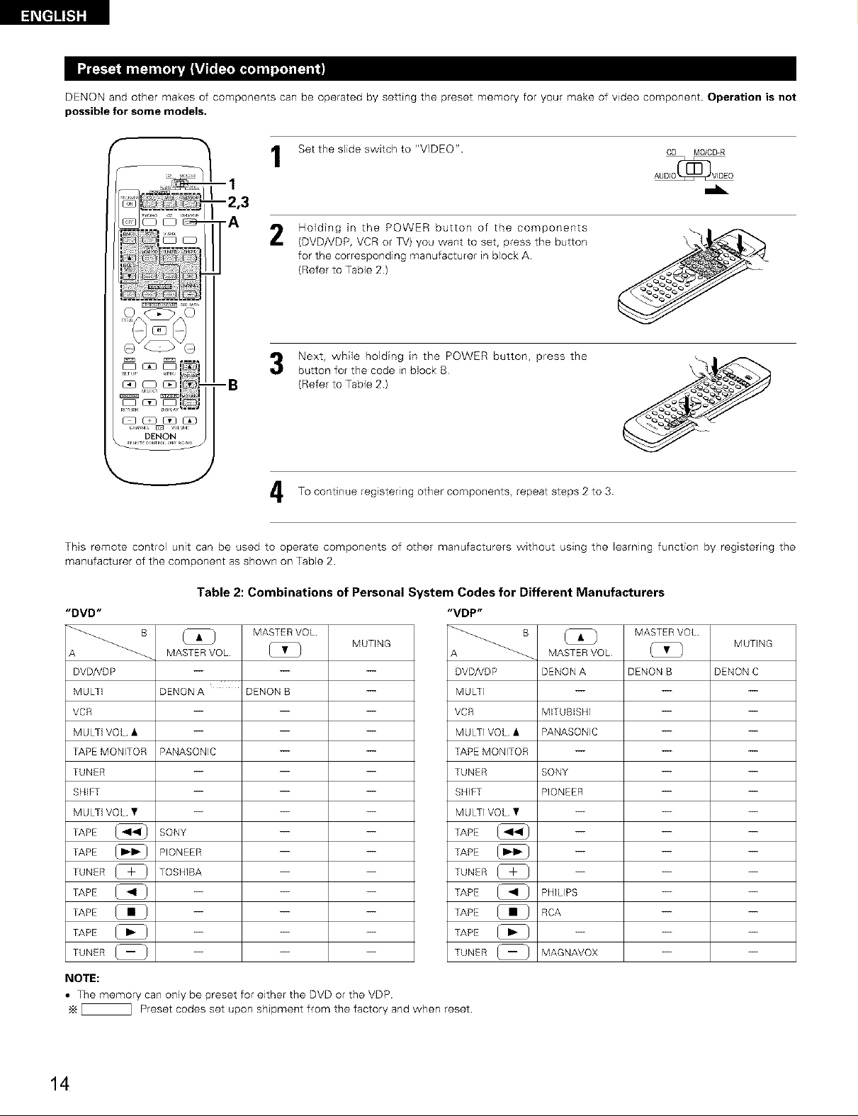
DENON and other makes of components can be operated by setting the preset memory for your make of video component. Operation is not
possible for some models.
Set the slide switch to "VIDEO". CD MD/CD-R
--I
..L
-2,3
-A
This remote control unit can be used to operate components of other manufacturers without using the learning function by registering the
manufacturer of the component as shown on Table 2.
Table 2: Combinations of Personal System Codes for Different Manufacturers
"DVD"
MASTER VOL
A _
DVD/YDP
MULTi
VCR
MULTi VOL •
TAPEMONITOR
TUNER
SHIFT
MULTi VOL •
TAPE
TAPE
TUNER [_ }
TAPE @
TAPE
TAPE @
TUNER _
NOTE:
• The memory can only be preset for either the DVD or the VDP.
_ Preset codes set upon shipment from the factory and when reset
MASTERVOL [_ }
DENON A DENON B --
PANASONIC -- --
SONY -- --
PIONEER -- --
TOSHIBA -- --
Holding in the POWER button of the components
2
(DVD/VDP, VCR or TV) you want to set, press the button
for the corresponding manufacturer in block A.
(Refer to Table 2.)
Next, while holding in the POWER button, press the
button for the code in block B
(Refer to Table 2.)
To continue registering other components, repeat steps 2 to 3
"VDP"
MUTING
DVD/YDP
MULTI
VCR
MULTI VOL •
TAPE MONITOR
TUNER
SHIFT
MULTI VOL •
TAPE
TAPE
TUNER [_ _
TAPE @
TAPE
TAPE @
TUNER _
SONY -- --
MASTER VOL
MASTER VOL (_ }
DENON A DENON B DENON C
MITUBISHI -- --
PANASONIC -- --
PIONEER -- --
PHILIPS -- --
RCA -- --
MAGNAVOX -- --
MUTING
14
"VCR"
MASTER VOL
MUTING
A _
DVD/VDP
MULTi
VCR
MULTi VOL •
TAPE MONITOR
TUNER
SHIFT
MULTi VOL •
TAPE
TAPE
TUNER _-_
TAPE
TAPE
TAPE
TUNER (_
B
MASTER VOL
HITACHI A HETACHI B
MITUBISHi A MITUBISHI B MITUBISHE C
PANASONIC A PANASONIC B PANASONIC C
JVC (VICTOR) A JVC (VICTOR) B JVC (VICTOR) C
SONY A SONY B SONY C
PIONEER -- --
TOSHIBA A TOSHIBA B
SANYO A SANYO B --
SHARP A SHARP B --
NEC A NEG B NEC C
PHILIPS A PHILIPS B PHLIPS C
RCA A RCA B --
GENERAL GENERAL
ELECTREC A ELECTRIC B
MAGNAVOX A MAGNAVOX B MAGNAVOX C
_ Preset codes set upon shipment from the factory and when reset
"TV"
DVD/VDP
MULTI
VCR
MULTI VOL •
TAPE MONITOR
TUNER
SHIFT
MULTi VOL •
TAPE
TAPE
TUNER [_
TAPE
TAPE
TAPE
TUNER (_
MASTER VOL
MASTER VOL
HITACHI -- --
MITUBISHI A MITUBISHI B
PANASONIC A PANASONIC B
JVC (VICTOR) -- --
SONY -- --
PIONEER -- --
TOSHIBA -- --
SANYO -- --
SHARP -- --
NEC -- --
PHILIPS -- --
RCA -- --
GENERAL GENERAL __
ELECTRIC A ELECTRIC B
MAGNAVOX -- --
MUTING
NOTES:
• The signals for the pressed buttons are emitted while setting the preset memory To avoid accidental operation, cover the remote
control unit's transmitting window while setting the preset memory.
• Some models and years of manufacture of components of the manufacturers listed on Table 2 cannot be used
• The unit is equipped with several types of remote control codes which depend on the manufacturer. If there is no operation when set to
A, please change the setting to B or C and try again
15
Set the slide switch to "VIDEO".
1
Operate the video component.
• For details, refer to the component's operating instructions.
•_ Some models cannot be operated with this remote control unit.
a. For DVD player
POWER : Power on/off
• : Stop
I_ : Play
1_1_1,11_1_1 : Auto search (cue)
n : Pause
TITLE : Call out title
MENU : Call out menu
DISPLAY : Switch display
SET UP : DVD setup
RETURN : Menu return
•, • : Cursor up/down
_1, I_ : Cursor left/right
SELECT : Enter setting
DISC SKIP + : Disc selection
NOTE:
i_l_Tul_ U_HA¥
Some manufacturers use different names for the DVD
remote control buttons, so also refer to the instructions
on remote control for that component.
CD MD/CD-R
AUDIO(_ VIDEO
--1
--2
-2-c
b. For video disc player (VDP}
POWER : Power on/off
414,1_1_ : Manual search
(reverse and forward)
• : Stop
I_ : Play
144,11_J_ : Auto search (cue)
II : Pause
c, For video deck (VCR}
[_ GD I_1 G3
(:3D(:_ (2El I2D
[Z3 (2D (3D GD
POWER : Power on/off
4_11,1_1 _ : Manual search
(reverse and forward)
• : Stop
I_ : Play
CHANNEL: Switch channel
+,-
d. For TV
O^_E:::>^O
00 0o
POWER : Power on/off
VOLUME : Volume
• , ¥ up/down
CHANNEL: Switch channel
+ ,-
NOTE:
The TV can be operated when the
switch is at any position
16
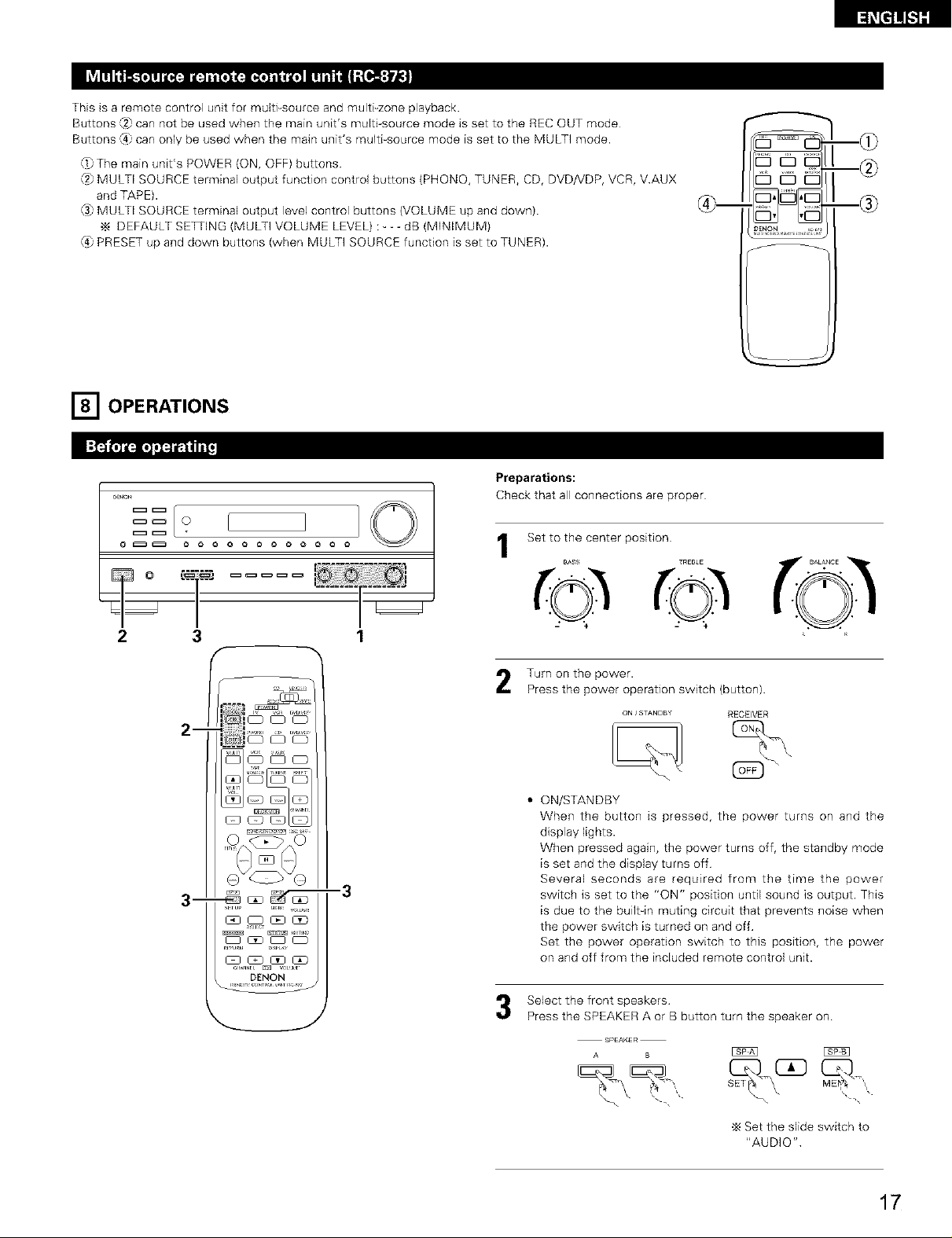
This is a remote control unit for multPsource and multFzone playback.
Buttons ,_2)can not be used when the main unit's multi source mode is set to the REC OUT mode
Buttons ,q) can only be used when the main unit's multi-source mode is set to the MULTI mode.
O}The main unit's POWER (ON, OFF) buttons
(2)MULTI SOURCE terminal output function control buttons (PHONO, TUNER, CD, DVD/VDP, VCR, VAUX
and TAPE).
(3}MULTI SOURCE terminal output level control buttons (VOLUME up and down)
DEFAULT SETI ING (MULTI VOLUME LEVEL) : - - - dB (MINIMUM)
(4}PRESET up and down buttons (when MULTI SOURCE function is set to TUNER).
r_ OPERATIONS
[_i_t]] Loading...