


SIG110
MODELS SIG80 / SIG80M / SIG110 / SIG110D / SIG110H
INSTALLATION AND OPERATING INSTRUCTIONS
VENTILATION FAN / LIGHT / NIGHT LIGHT
READ AND SAVE THESE INSTRUCTIONS
GENERAL SAFETY INFORMATION
1. Make sure that the electric service supply voltage is AC
120V, 60Hz.
2. Follow all local electrical and safety codes, as well as the
National Electrical Code (NEC) and the Occupational
Safety and Health Act (OSHA).
3. Always disconnect the power source before working on
or near the ventilating fan, motor or junction box.
4. Protect the power cord from sharp edges, oil, grease, hot
surfaces, chemicals or other objects.
5. Do not kink the power cord.
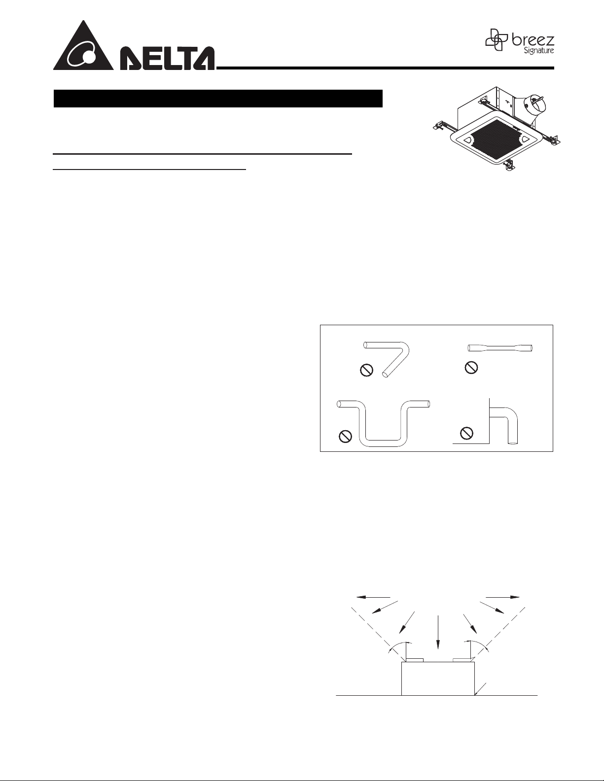
6. Do not install the unit where ducts are congured as
shown in Fig. A.
7. Provide suction parts with prop
8. This unit is UL listed for use over a bathtub or shower
when installed in a GFCI protected branch circuit.
9. These ventilating fans are intended for residential usage
only.
er ventilation.
WARNING
TO REDUCE THE RISK OF FIRE, ELECTRIC SHOCK, OR
INJURY TO PERSONS, OBSERVE THE FOLLOWING:
1. Use this unit only in the manner intended by the
manufacturer. If you have questions, contact the
manufacturer.
2. Before servicing or cleaning the unit, switch the power
o on the service panel and lock the service
disconnecting means to prevent power from being
switched on accidentally. When the servic
means cannot be locked, securely fasten a prominent
warning device, such as a tag, to the service panel.
3. Installation work and electrical wiring must be done by
qualied person(s) in accordance with all applicable
codes and standards, including re-rated construction.
4. Sucient air is needed for proper combustion and
exhausting of gases through the ue (chimney) of fuel
burning equipment to prevent back drafting. Follow the
heating equipment manufacturer’s guideline and safety
standards such as those published by the National Fire
Protection Association (NFPA), and the Amer
for Heating, Refrigeration and Air Conditioning Engineers
(ASHRAE) and local code authorities.
5. When cutting or drilling into the wall or ceiling, do not
damage electrical wiring and other hidden utilities.
6. Ducted fans must always be vented to the outdoors.
e disconnecting
ican Society
7. If this unit will be installed over a tub or shower, it must
be marked as appropriate for the application and be
connected to a GFCI (Ground Fault Circuit Interrupter) –
protected branch circuit.
8. Do not use this unit with any other solid-state control
devices. Solid-state control devices may cause harmonic
distortion, which can cause a motor humming noise.
9. NEVER place a switch where it can be reached fr
or shower.
Not to be installed in a ceiling thermally insulated to a value
10.
greater than R40. (This is required for installation in Canada
only).
Turning angle too large Duct shrink
CAUTION
1. For general ventilating use only. Do not use to exhaust
hazardous or explosive materials and vapors.
2. Not for use in cooking areas. (Fig. B)
3. This product must properly connect to the grounding
conductor of the supply circuit.
4. To reduce the risk of injury to persons, install the fan at
least 7 feet (2.1m) above the oor.
Fig. A
Cooking area
Do not install above or
inside this area
°
5
4
Cooking
Equipment
Fig. B
Body
4
Page 1.
om a tub
ydob eht raen woblEswoble ynam ooT
5
°
floor
Part name
Appearance
Quantity
For models of:
SIG110H, SIG110D
For model of:
MODELS SIG80 / SIG80M / SIG110 / SIG110D / SIG110H
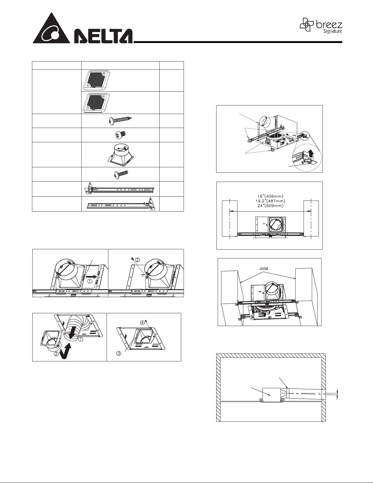
SUPPLIED ACCESSORIES
Grille
Tapping Screw
(ψ
4x25)
Screw
#8- 32x1/4”
SIG80, SIG110,
SIG80M
1
1
4
4
1-5. Secure the suspension brackets to the joists with nails or
by using the tapping screws (ψ4x25) through holes near nails.
1-6. Secure the suspension bracket to the fan body using the
screws (#8-32 x 1/4").
1-7. Follow steps 2 to 6 of the installation to complete the
installation work.
Body
Suspension
Bracket I
Page 2.
Duct connector
Duct Screw
(M4x12)
Suspension bracket I
13”(318.5)
Suspension bracket II
13”
(318.5)
Inches (mm)
INSTALLATIONS
1
1
2
2
Attach Duct Connector
Option 1. Attach the duct connector from outside and secure using
the duct screw (M4X12).
Insert tab into
slot in housing
Duct screw(M4X12)
from Parts Bag
Option 2. Attach the duct connector from the housing can inside, and
secure using the duct screw (M4X12).
Duct screw(M4X12)
from Parts Bag
Suspension
Bracket II
Tab
Fig. C
Fig. D
Fig. E
Pull existing ductwork
into Housing
Note: Remove the tape from the damper and adaptor before installation.
Insert tab into slot
in Housing
1. Using suspension brackets
1-1. Sliding suspension brackets are available to allow for positioning
of the housing anywhere between joists up to a span of 24”.
1-2. Insert the suspension brackets into the channels on the housing.
sure
Make
the tabs face up as shown. (Fig. C)
1-3. Extend the suspension brackets to t the width of the joists. Hold the
an in place by wrapping the suspension bracket tabs around the
f
bottom of the joist. Mak e sure the fan body is level and
perpendicular to the joist. (Fig. D & E)
1-4. Ensure that the distance between the ceiling and fan body is
appropriate for mounting the grille.
2. Duct connection
Ceiling
Body
Inside
Tape
Duct
Outside
Gradient
1°~2°
Fig. F
2-1. Insert the duct into the duct connector and tape all duct-
work connections to make them secure and airtight. (Fig. F)
2-2. Install the duct with a gradient 1°~2° to the outside.
 Loading...