


 Loading...
www.delta.com.tw/industrialautomation
ASIA
Delta Electronics, Inc.
Taoyuan1
31-1, Xingbang Road, Guishan Industrial Zone,
Taoyuan County 33370, Taiwan, R.O.C.
TEL: 886-3-362-6301 / FAX: 886-3-362-7267
Delta Electronics (Jiang Su) Ltd.
Wujiang Plant3
1688 Jiangxing East Road,
Wujiang Economy Development Zone, Wujiang City, Jiang Su Province,
People's Republic of China (Post code: 215200) TEL: 86-512-6340-3008 / FAX: 86-769-6340-7290
Delta Electronics (Japan), Inc.
Tokyo Office
Delta Shibadaimon Building, 2-1-14 Shibadaimon,
Minato-Ku, Tokyo, 105-0012, Japan
TEL: 81-3-5733-1111 / FAX: 81-3-5733-1211
Delta Electronics (Korea), Inc.
Donghwa B/D 3F, 235-6, Nonhyun-dong,
Kangnam-gu, Seoul 135-010, Korea
TEL: 82-2-515-5303/5 / FAX: 82-2-515-5302
Delta Electronics (Singapore) Pte. Ltd.
8 Kaki Bukit Road 2, #04-18 Ruby Warehouse Complex, Singapore 417841
TEL: 65-6747-5155 / FAX: 65-6744-9228
AMERICA
Delta Products Corporation (USA)
Raleigh Office
P.O. Box 12173,5101 Davis Drive,
Research Triangle Park, NC 27709, U.S.A.
TEL: 1-919-767-3813 / FAX: 1-919-767-3939
EUROPE
Deltronics (The Netherlands) B.V.
Eindhoven Office
De Witbogt 15, 5652 AG Eindhoven, The Netherlands
TEL: 31-40-2592850 / FAX: 31-40-2592851
*We reserve the right to change the information in this manual without prior notice |
20080122 |
 Series
HMI Connection Manual
Manual Connection HMI Series
Delta DOP Series HMI Connection Manual|DOP-A/AE/AS Series
1.1Pin Definition of Serial Communication
DOP-A Series |
|
|
|
|
|
|
|
||
COM1 |
|
|
|
|
|
|
|
||
|
|
|
|
|
|
|
|
|
|
|
|
|
|
|
|
PIN |
Mode |
|
|
|
|
|
|
|
|
RS-232 |
|
||
|
|
|
|
|
|
|
|
||
|
|
|
|
|
|
1 |
N.C |
|
|
|
|
|
Pin1 |
|
2 |
RXD |
|
||
|
|
|
|
|
|
|
|||
|
|
|
|
|
|
3 |
TXD |
|
|
|
|
|
|
|
|
4 |
N.C |
|
|
|
|
|
|
|
|
5 |
GND |
|
|
|
|
|
|
|
|
6 |
N.C |
|
|
|
|
|
|
|
|
7 |
RTS |
|
|
|
|
|
|
|
|
8 |
CTS |
|
|
|
|
|
|
|
|
9 |
N.C |
|
|
COM2 |
|
|
|
|
|
|
|
|
|
|
|
|
|
|
|
|
|
|
|
|
|
|
PIN |
|
Mode 1 |
Mode 2 |
|
Mode 3 |
|
|
|
|
|
RS-232 |
RS-422 |
|
RS-485 |
||
|
|
|
|
|
|
||||
|
|
|
1 |
|
N.C |
RXD- |
|
D- |
|
|
|
Pin1 |
2 |
|
RXD |
RXD+ |
|
D+ |
|
|
|
|
3 |
|
TXD |
TXD+ |
|
D+ |
|
|
|
|
4 |
|
N.C |
TXD- |
|
D- |
|
|
|
|
5 |
|
GND |
GND |
|
GND |
|
|
|
|
6 |
|
N.C |
RTS- |
|
N.C |
|
|
|
|
7 |
|
RTS |
RTS+ |
|
N.C |
|
|
|
|
8 |
|
CTS |
CTS+ |
|
N.C |
|
|
|
|
9 |
|
N.C |
CTS- |
|
N.C |
|
|
|
|
|
|
|
|
|
|
|


 NOTE
NOTE
1)Mode 3 is for RS-485. Pin 2 & 3 are D+ and pin 1 & 4 are D-.
2)Grounding is highly recommended if RS-485 & RS-422 are used for long transmission.
3)DO NOT connect Frame Ground (FGND) to GND. Please connect FGND to the outer covering of connector.
4)Transmission speed is relevant to distance and baud rate.
Revision January, 2008, Doc. Name: 2007PDD23000007 |
1-1 |
Delta DOP Series HMI Connection Manual|DOP-A/AE/AS Series
DOP-AE Series COM1
|
PIN |
Mode |
|
RS-232 |
|
|
|
|
|
1 |
N.C |
Pin1 |
2 |
RXD |
|
||
|
3 |
TXD |
|
4 |
N.C |
|
5 |
GND |
|
6 |
N.C |
|
7 |
RTS |
|
8 |
CTS |
|
9 |
N.C |
|
|
|
COM2/COM3 |
|
|
|
|
|
|
|
|
PIN |
Mode 1 |
Mode 2 |
Mode 3 |
Mode 4 |
Mode 5 |
Mode 6 |
|
RS-232 |
RS-422 |
RS-485 |
RS-232x2 RS-422x2 |
RS-485x2 |
||
|
|
||||||
|
1 |
N.C |
RXD- |
D- |
N.C |
RXD- |
D- |
Pin1 |
2 |
RXD |
RXD+ |
D+ |
RXD |
RXD+ |
D+ |
COM2 |
3 |
TXD |
TXD+ |
D+ |
TXD |
TXD+ |
D+ |
|
4 |
N.C |
TXD- |
D- |
N.C |
TXD- |
D- |
|
5 |
GND |
GND |
GND |
GND |
GND |
GND |
|
6 |
N.C |
RTS- |
N.C |
N.C |
TXD- |
D- |
COM3 |
7 |
RTS |
RTS+ |
N.C |
TXD |
TXD+ |
D+ |
|
8 |
CTS |
CTS+ |
N.C |
RXD |
RXD+ |
D+ |
|
9 |
N.C |
CTS- |
N.C |
N.C |
RXD- |
D- |
1-2 |
Revision January, 2008, Doc. Name: 2007PDD23000007 |
Delta DOP Series HMI Connection Manual|DOP-A/AE/AS Series
DOP AS Series COM1/COM3
|
|
PIN |
Mode 1 |
Mode 2 |
|
|
RS-232 |
RS-232x2 |
|
|
|
|
||
|
|
1 |
N.C |
N.C |
Pin1 |
|
2 |
RXD |
RXD |
|
COM 1 |
3 |
TXD |
TXD |
|
|
4 |
N.C |
N.C |
|
|
5 |
GND |
GND |
|
|
|||
|
|
|
|
|
|
|
6 |
N.C |
N.C |
|
COM 3 |
7 |
RTS |
TXD |
|
|
8 |
CTS |
RXD |
|
|
9 |
N.C |
N.C |
|
|
|
|
|
COM2
|
PIN |
Mode 1 |
Mode 2 |
|
|
|
|
|
RS-422 |
RS-485 |
|
|
|
||
|
|
|
|
|
R- |
RXD- |
D- |
|
|
|
|
|
R+ |
RXD+ |
D+ |
|
|
|
|
|
T- |
TXD- |
D- |
|
|
|
|
|
T+ |
TXD+ |
D+ |
|
|
|
|
|
|
GND |
GND |
|
|
|
|
Revision January, 2008, Doc. Name: 2007PDD23000007 |
1-3 |
Delta DOP Series HMI Connection Manual|DOP-A/AE/AS Series
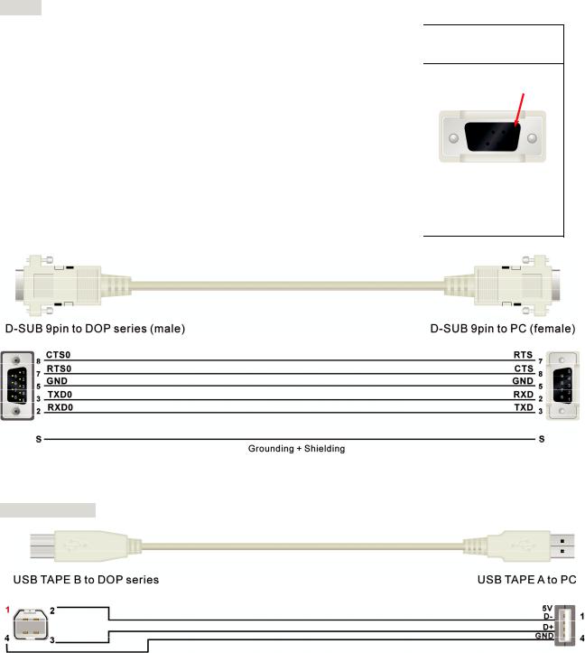
1.2 Cable for Download
Download via COM Port
RS-232
DOP series HMI |
|
|
PC |
|
9 pin D-SUB male (RS-232) |
9 pin D-SUB female (RS-232) |
|||
|
|
|
|
|
RXD (2) |
|
|
(3) |
TXD |
|
|
|||
TXD (3) |
|
|
(2) |
RXD |
|
|
|||
GND (5) |
|
|
(5) GND |
|
|
|
|||
RTS (7) |
|
|
(8) CTS |
|
|
|
|||
CTS (8) |
|
|
(7) RTS |
|
|
|
|||
|
|
|
|
|
Controller
Pin1
Download via USB Flash Drive
USB Connection
1-4 |
Revision January, 2008, Doc. Name: 2007PDD23000007 |
Delta DOP Series HMI Connection Manual|DOP-A/AE/AS Series
1.3Supported Controllers and Devices
Please refer to the following table for supported controllers and devices provided by DOP series HMI.
Brand |
Controller Name / Series Name |
|
|
|
|
|
Delta Controller |
|
Delta |
For Servo/AC drive/Temperature Controller/PLC |
|
(984 RTU mode / ASCII mode) |
||
|
|
|
|
Delta DVP PLC |
|
|
|
|
Allen Bradley |
MicroLogix PLC |
|
|
||
SLC5 PLC |
||
|
||
|
|
|
Cimon |
Loader Protocol |
|
|
|
|
Copley |
Servo (Stepnet Protocol) |
|
|
|
|
Danfoss |
VLT 2800 (FC Protocol) |
|
|
|
|
Emerson |
EC20 Series PLC |
|
|
|
|
Facon |
FB Series PLC |
|
|
|
|
Festo |
Festo PLC |
|
|
|
|
GE Fanuc |
90 Series SNP PLC |
|
|
|
|
Hitachi |
EH Series |
|
|
|
|
Hust |
Hust CNC Controller |
|
|
|
|
Jetter |
Nano Series PLC |
|
|
||
JC Series PLC |
||
|
||
|
|
|
Keyence |
KV/KZ Series |
|
|
|
|
Koyo |
SU/DL Series |
|
|
||
K-Sequence |
||
|
||
|
|
|
Lenze |
LECOM-A/B Protocol |
|
|
|
|
|
Master-K120S/200S |
|
|
|
|
LG |
Glofa GM6 CNET |
|
|
||
Master-K CNET |
||
|
||
|
|
|
|
XGT CNET |
|
|
|
|
LI YAN |
LYPLC EX |
|
|
|
|
M2i |
M2i Master |
|
|
||
M2i Slave |
||
|
||
|
|
|
Matsushita |
FP Series |
|
|
|
|
Mirle |
FAMA SC |
|
|
|
Revision January, 2008, Doc. Name: 2007PDD23000007 |
1-5 |
Delta DOP Series HMI Connection Manual|DOP-A/AE/AS Series
Brand |
Controller Name / Series Name |
||
|
|
|
|
|
FX / FX2N |
||
|
|
|
|
|
FX3U |
||
|
|
|
|
|
A Series/J71UC24 |
||
|
|
|
|
Mitsubishi |
Mitsubishi A2A/A2AS/A2USH A1SH/A3N/A2ASH CPU Port |
||
|
|
||
Q Series CPU Port |
|||
|
|||
|
|
|
|
|
Q Series Computer Link |
||
|
|
|
|
|
FX Series Computer Link |
||
|
|
|
|
|
J2s Series |
||
|
|
|
|
|
BY125 |
||
MKS |
|
|
|
CT150 |
|||
|
|
|
|
|
MC700/720 |
||
|
|
|
|
|
Modbus (Master) --- 984 RTU / ASCII mode |
||
|
|
|
|
Modbus |
Hexadecimal Address (Master) --- RTU / ASCII mode |
||
|
|
||
nW (Master) --- RTU / ASCII mode |
|||
|
|||
|
|
|
|
|
Modbus (Slave) --- RTU / ASCII mode |
||
|
|
|
|
|
TSX Micro |
Uni-Telway |
|
Modicon |
|
||
Modbus RTU |
|||
|
|||
|
|
|
|
|
TWIDO |
||
|
|
||
Moeller |
Moeller PLC |
||
|
|
||
NIKKI DENSO |
NCS-FI/FS Series |
||
|
|
||
|
C Series |
||
Omron |
|
||
CJ1/CS1 Series |
|||
|
|
||
|
TPM1A |
||
|
|
||
|
S7 200 |
||
|
|
||
Siemens |
S7-300 (with PC Adaptor) |
||
|
|
||
|
S7-300 (without PC Adaptor) |
||
|
|
||
Taian |
TP02 PLC |
||
|
|
||
Vigor |
M Series |
||
|
|
||
VIPA |
VIPA PLC |
||
|
|
||
Yokogawa |
ACE PLC |
||
|
|
|
|
1-6 |
Revision January, 2008, Doc. Name: 2007PDD23000007 |

Delta DOP Series HMI Connection Manual|DOP-A/AE/AS Series
Delta (Servo/AC Drive/PLC/Temperature) Controller |
Back to Table |
A. HMI factory setting
Baud rate: ASCII: 9600, 7, None, 2.
RTU: 9600, 8. None, 2.
Controller station number: 1.
Control area/status area: None.


 NOTE
NOTE
1)This driver can support all Delta products, i.e. AC drive, PLC, Servo, Temperature Controller and Modbus standard connection. The users can easily set and communicate with these devices via using this driver.
2)For people who are using Modbus standard connection:
Modbus / ASCII (Master), Modbus / 984 RTU (Master), Modbus / ASCII Hex Address (Master) and Modbus / RTU Hex Address (Master) can be compatible with the new Delta controller ASCII and Delta controller RTU. To change the driver settings, the user only needs to change the “Controller” Option which is used to set the controller, then the new driver can be used immediately.
B. Definition of controller Read/Write address
Registers
Register Type |
Format |
Read/Write Range |
Data Length |
||
Word No. |
|
Bit No. |
|||
|
|
|
|
||
Servo communication |
SERVO-n |
n: 0 ~ 0700h |
N/A |
|
Word |
address |
|
||||
|
|
|
|
|
|
|
|
|
|
|
|
AC drive communication |
INVERTER-n |
n: 0 ~ 2299h |
N/A |
|
Word |
address |
|
||||
|
|
|
|
|
|
|
|
|
|
|
|
TCntrl communication |
TEMP_CTRL-n |
n: 0 ~ 6000h |
N/A |
|
Word |
address |
|
||||
|
|
|
|
|
|
WORD_DEVICE_X |
PLC_Xn |
n: 0 ~ 360(octal) |
N/A |
|
Word |
|
|
|
|
|
|
WORD_DEVICE_Y |
PLC_Yn |
n: 0 ~ 360(octal) |
N/A |
|
Word |
|
|
|
|
|
|
WORD_DEVICE_M |
PLC_Mn |
n: 0 ~ 1520, |
N/A |
|
Word |
|
|
1536 ~ 4080 |
N/A |
|
Word |
|
|
|
|
|
|
WORD_DEVICE_S |
PLC_Sn |
n: 0 ~ 1008 |
N/A |
|
Word |
|
|
|
|
|
|
WORD_DEVICE_T |
PLC_Tn |
n: 0 ~ 255 |
N/A |
|
Word |
|
|
|
|
|
|
WORD_DEVICE_C |
PLC_Cn |
n: 0 ~ 199 |
N/A |
|
Word |
|
|
|
|
|
|
WORD_DEVICE_D |
PLC_Dn |
n: 0 ~ 4095, |
N/A |
|
Word |
|
|
4096 ~ 9999 |
N/A |
|
Word |
|
|
|
|
|
|
WORD_DEVICE_HC |
PLC_HCn |
n: 200 ~ 255 |
N/A |
|
Double Word |
|
|
|
|
|
|
PLC communication |
PLC_Modulen |
n: 4000 ~ 4499h |
N/A |
|
Word |
address Module |
|
||||
|
|
|
|
|
|
Revision January, 2008, Doc. Name: 2007PDD23000007 |
1-7 |

Delta DOP Series HMI Connection Manual|DOP-A/AE/AS Series
Register Type |
|
Format |
|
Read/Write Range |
Data Length |
||
|
Word No. |
|
Bit No. |
||||
|
|
|
|
|
|||
Output Registers |
RW-n |
|
n: 0 ~ FFFFh |
N/A |
|
Word |
|
|
|
|
|
|
|
|
|
Input Registers |
R-n |
|
n: 0 ~ FFFFh |
N/A |
|
Word |
|
|
|
|
|
|
|
|
|
Output Registers |
Wn |
|
n: 40001 |
~ 50000 |
N/A |
|
Word |
|
|
|
|
|
|
|
|
Input Registers |
Wn |
|
n: 30001 |
~ 40000 |
N/A |
|
Word |
|
|
|
|
|
|
|
|


 NOTE
NOTE
1)The above addresses of Servo, AC drive, Temperature controller and PLC Module are in hexadecimal format. PLC Word Device X and Y are in octal format. Other PLC Word Device M, S, T, C, D and HC are in decimal format.
2)WORD_DEVICE_ X / WORD_DEVICE_Y / WORD_DEVICE_M / WORD_DEVICE_S: Address must be 0 or the multiple of 16.
Contacts
Contact type |
Format |
Read/Write Range |
||
Word No. |
|
Bit No. |
||
|
|
|
||
Servo communication address |
SERVO-n.b |
n: 0 ~ 0700h |
|
b: 0 ~ f |
|
|
|
|
|
AC drive communication address |
INVERTER-n.b |
n: 0 ~ 2299h |
|
b: 0 ~ f |
|
|
|
|
|
TCntrl communication address |
TEMP_CTRL-n.b |
n: 0 ~ 6000h |
|
b: 0 ~ f |
|
|
|
|
|
Servo Digital Input |
SERVO_DI-n |
N/A |
|
n: 1 ~ 8 |
|
|
|
|
|
Servo Digital Output |
SERVO_DO-n |
N/A |
|
n: 1 ~ 5 |
|
|
|
|
|
WORD_DEVICE_X |
PLC_Xn |
N/A |
|
n: 0 ~ 377(octal) |
|
|
|
|
|
WORD_DEVICE_Y |
PLC_Yn |
N/A |
|
n: 0 ~ 377(octal) |
|
|
|
|
|
WORD_DEVICE_M |
PLC_Mn |
N/A |
|
n: 0 ~ 1535 |
|
|
|
|
1536 ~ 4095 |
|
|
|
|
|
WORD_DEVICE_S |
PLC_Sn |
N/A |
|
n: 0 ~ 1023 |
|
|
|
|
|
WORD_DEVICE_T |
PLC_Tn |
N/A |
|
n: 0 ~ 255 |
|
|
|
|
|
WORD_DEVICE_C |
PLC_Cn |
N/A |
|
n: 0 ~ 255 |
|
|
|
|
|
TCntrl Bit communication address |
TEMP_CTRLB-n |
N/A |
|
n: 800 ~ 8FFh |
|
|
|
|
|
Discrete Outputs |
RWB-n |
N/A |
|
n: 0 ~ FFFFh |
|
|
|
|
|
Discrete Inputs |
RB-n |
N/A |
|
n: 0 ~ FFFFh |
|
|
|
|
|
Discrete Outputs |
Bn |
N/A |
|
n: 1 ~ 10000 |
|
|
|
|
|
Discrete Inputs |
Bn |
N/A |
|
n: 10001 ~ 20000 |
|
|
|
|
|


 NOTE
NOTE
1)The above addresses of Servo, AC drive, Temperature controller and PLC Module are in hexadecimal format.
1-8 |
Revision January, 2008, Doc. Name: 2007PDD23000007 |
Delta DOP Series HMI Connection Manual|DOP-A/AE/AS Series
2)PLC Word Device X and Y are in octal format. Other PLC Word Device M, S, T, C, D and HC are in decimal format.
3)Servo Digital Input and Servo Digital Output are only for Servo.
Pay close attention to the following important notes:
4)For Delta AC drive:
Communication address for HMI read/write address uses hexadecimal format. For detailed information about communication address of Delta AC drive, please refer to Delta AC drive “User Manual”.
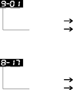
Example 1: Parameter 9-01 of Delta VFD-S drive Transmission Speed needs to be set to INVERTER901 in HMI. (Decimal 9 is converted to 09 in hexadecimal and 01 is converted to 01 in hexadecimal. Therefore, setting INVERTER901 to HMI will discard the first 0)
 Decimal value
 Hexadecimal value
01
09
(Hexadecimal value)
(Hexadecimal value)
The communication address of parameter 9-01 is 0901H.
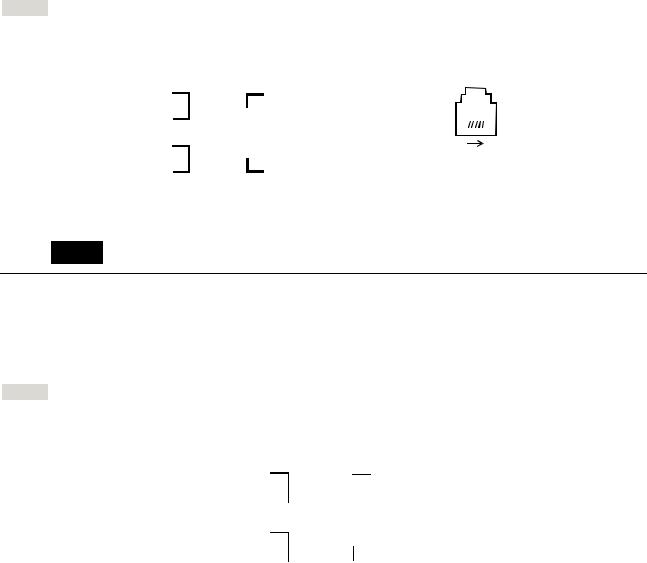
Example 2: if setting of parameter 8-17 (Lower Bound of DC Braking Start-up Frequency) of Delta VFD- S drive is desired, user needs to set INVERTER811 in HMI. (8 is converted to 08 in hexadecimal and 17 is converted to 11 in hexadecimal. Therefore, setting the INVERTER811 to HMI will discard the first 0)
 Decimal value
 Hexadecimal value
11
08
(Hexadecimal value)
(Hexadecimal value)
The communication address of parameter 8-17 is 0811H.
5) For Delta Servo drive:
yHMI Read/Write address setting needs to input the communication address listed in SERVO “User Manual”.
yServo Digital Input and Servo Digital Output are only for Servo.
6)For Delta Temperature Controller (DTA series):
HMI can be set up to connect to several Delta A series temperature controllers on standard Modbus networks by using RTU transmission mode. However, the communication delay time may need to increase. Therefore, 5ms or longer is highly recommended.
Revision January, 2008, Doc. Name: 2007PDD23000007 |
1-9 |
Delta DOP Series HMI Connection Manual|DOP-A/AE/AS Series
C. Connections (Connector Pinouts)
Delta Servo
RS-232
|
DOP Series |
Controller |
|
Controller |
|
|
|
CN3 cable connector |
|
||
|
9 pin D-SUB male (RS-232) |
CN3 cable connector (RS-232) |
|
|
|
|
|
(RS-232) |
|
||
|
|
|
|
|
RXD (2) |
|
|
(2) TX |
|
|
|
|
|
|
|
|
|
|
|
|
|
|
|
|||
|
|
1 |
3 |
5 |
||||||
TXD (3) |
|
|
|
(4) RX |
||||||
|
|
|
|
|
|
|
|
|
||
|
|
|
2 |
4 |
6 |
|||||
|
|
|
|
|
||||||
GND (5) |
|
(1) GND |
Top View |
|||||||
|
||||||||||
RS-422
DOP Series |
|
Controller |
|
Controller |
|||||||||
|
CN3 cable connector |
||||||||||||
9 pin D-SUB male (RS-422) |
CN3 cable connector (RS-422) |
||||||||||||
|
|
(RS-422) |
|||||||||||
|
|
|
|
|
|
|
|||||||
RXD+ (2) |
|
|
(5) TX+ |
|
|
|
|
|
|
|
|
||
|
|
|
|
|
|
|
|
|
|
||||
RXD- (1) |
|
|
(6) TX- |
|
|
|
|
|
|
|
|
||
|
|
|
|
|
|
|
|
|
|
|
|||
|
|
|
|
1 |
3 |
5 |
|||||||
|
|
||||||||||||
TXD+ (3) |
|
|
(3) RX+ |
|
|
|
|
|
|
|
|||
|
|
2 |
|||||||||||
|
|
|
4 |
6 |
|||||||||
|
|
||||||||||||
TXD- (4) |
|
|
(4) RX- |
Top View |
|||||||||
|
|
|
|
|
|
|
|
|
|
||||
|
|
|
|
|
|
|
|
|
|
|
|
|
|
RS-485
DOP Series |
|
|
Controller |
|
Controller |
|||||||||
|
|
CN3 cable connector |
||||||||||||
9 pin D-SUB male (RS-485) |
CN3 cable connector (RS-485) |
|||||||||||||
|
|
(RS-485) |
||||||||||||
|
|
|
|
|
|
|
|
|||||||
RXD+ (2) |
(3) 485+ |
|
|
|
|
|
|
|
|
|||||
TXD+ (3) |
|
|
|
|
|
|
|
|
|
|
|
|
|
|
|
|
|
|
(5) 485+ |
|
1 |
3 |
5 |
|
|
||||
|
|
|
||||||||||||
|
|
|
|
|
|
|
|
|
|
|
|
|
||
|
|
2 |
||||||||||||
RXD- (1) |
(4) 485- |
|
4 |
6 |
||||||||||
TXD- (4) |
|
|
|
|
(6) 485- |
Top View |
||||||||
|
|
|
|
|||||||||||
|
|
|
|
|
|
|
|
|
|
|
|
|||
|
|
|
|
|
|
|
|
|
|
|
|
|
|
|
1-10 |
Revision January, 2008, Doc. Name: 2007PDD23000007 |
Delta DOP Series HMI Connection Manual|DOP-A/AE/AS Series
Delta AC drive
RS-485
DOP Series |
|
|
Controller |
|
|
|
|
|
Controller |
||
9 pin D-SUB male (RS-485) |
RJ-11 cable connector (RS-485) |
RJ-11 cable connector (RS-485) |
|||||||||
RXD+ (2) |
|
|
(4) SG+ |
|
|
|
|
|
2: GND |
||
|
|
|
|
|
|
|
|
|
|
|
|
TXD+ (3) |
|
|
|
|
|
|
|
|
3: SG- |
||
|
|
|
|
|
|
|
|
4: SG+ |
|||
|
|
|
|
|
|
|
|
|
|
|
|
RXD - (1) |
|
|
|
1 |
|
|
|
|
6 |
||
|
|
|
|
|
(3 ) SG- |
Top View |
|||||
TXD- (4) |
|
|
|||||||||
|
|
DO NOT use Pin 1, 5 and 6 while |
|||||||||
GND (5) |
|
|
|
|
(2) GND |
||||||
|
|
|
using RS-485 communication. |
||||||||
|
|
|
|||||||||
|
|
|
|
|
|
|
|
|
|
|
|


 NOTE
NOTE
1)When connecting to a Delta VFD-M series AC drive, please connect Pin 5 (GND) of the Delta HMI and Pin 2 (GND) of the Delta VFD-M AC drive.
Temperature Controller
RS-485
DOP Series |
|
|
Controller |
||
9 pin D-SUB male (RS-485) |
|
|
RS-485 cable connector |
||
RXD+ (2) |
|
|
D+ |
||
|
|
||||
TXD+ (3) |
|
|
|
|
|
|
|
|
|
|
|
|
|
|
|
||
RXD- (1) |
|
|
|
||
TXD- (4) |
|
|
|
|
D- |
|
|
|
|
||
|
|
|
|
||
|
|
|
|
|
|
Revision January, 2008, Doc. Name: 2007PDD23000007 |
1-11 |

Delta DOP Series HMI Connection Manual|DOP-A/AE/AS Series
Delta DVP PLC Back to Table A. HMI factory settings
Baud rate: 9600, 7, Even, 1.
Controller station number: 1.
Control area/status area: D0 / D10.
B. Definition of controller Read/Write address
Registers
Register Type |
|
Format |
|
|
Read/Write Range |
|
|
|
|
Word No. |
Bit No. |
||
|
|
|
|
|
||
X_Data |
Xn |
|
n: 0 ~ 360(octal) |
N/A |
||
|
|
|
|
|
||
Y_Data |
Yn |
|
n: 0 ~ 360(octal) |
N/A |
||
|
|
|
|
|
||
M_Data |
Mn |
|
n: 0 ~ 1520, 1536 ~ 4080 |
N/A |
||
|
|
|
|
|
|
|
S_Data |
Sn |
|
n: 0 ~ |
1008 |
N/A |
|
|
|
|
|
|
|
|
T_Register |
Tn |
|
n: 0 |
~ |
255 |
N/A |
|
|
|
|
|
|
|
C_Register |
Cn |
|
n: 0 |
~ |
199 |
N/A |
|
|
|
|
|
|
|
D_Register |
Dn |
|
n: 0 |
~ 4095, 4096 ~ 9999 |
N/A |
|
|
|
|
|
|
||
HC_Register |
Cn |
|
n: 200 ~ 255 |
N/A |
||
|
|
|
|
|
|
|


 NOTE
NOTE
1)(W) is “Word”.
2)(DW) is “Double Word”.
3)X_Data / Y_Data / M_Data / S_Data: Address must be 0 or the multiple of 16.
Contacts
Contact type |
|
Format |
Read/Write Range |
||
|
Word No. |
|
Bit No. |
||
|
|
|
|
||
X_Data |
Xn |
|
N/A |
n: 0 |
~ 377(octal) |
|
|
|
|
|
|
Y_Data |
Yn |
|
N/A |
n: 0 |
~ 377(octal) |
|
|
|
|
|
|
M_Data |
Mn |
|
N/A |
n: 0 |
~ 1520, 1536 ~ 4080 |
|
|
|
|
|
|
S_Data |
Sn |
|
N/A |
n: 0 |
~ 1023 |
|
|
|
|
|
|
T_Coil |
Tn |
|
N/A |
n: 0 ~ 255 |
|
|
|
|
|
|
|
C_Coil |
Cn |
|
N/A |
n: 0 ~ 255 |
|
|
|
|
|
|
|
1-12 |
Revision January, 2008, Doc. Name: 2007PDD23000007 |
Delta DOP Series HMI Connection Manual|DOP-A/AE/AS Series
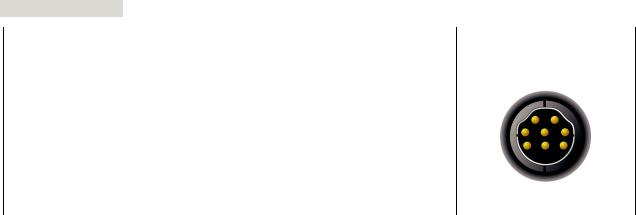
C. Connections (Connector Pinouts)
RS-232 Connection
DOP Series |
Controller |
Controller |
9 pin D-SUB male (RS-232) |
8 pin Mini DIN male (RS-232) |
8 pin Mini DIN male (RS-232) |
|
|
|
RXD (2) |
|
|
|
(5) TXD |
1 |
|
|||||
|
|
|
|
|||||||||||
|
|
|
|
|
|
|
|
|
|
|
|
|||
|
|
|
TXD (3) |
|
|
|
(4) RXD |
5 4 |
|
|||||
|
|
|||||||||||||
|
|
|
GND (5) |
|
|
|
(8) GND |
8 |
|
|||||
|
|
|
|
|
|
|
Top View |
|||||||
|
|
|
|
|||||||||||
|
|
|
|
|
|
|
|
|
|
|
|
|
||
|
|
|
|
|
|
|
|
|
|
|
|
|||
|
|
|
|
|
|
|
|
|
|
|
||||
RS-485 Connection |
|
|
|
|
|
|
|
|
||||||
|
|
|
|
|
|
|
|
|
|
|
|
|||
|
|
|
DOP Series |
|
|
|
|
|
|
Controller |
|
|||
|
|
9 pin D-SUB male (RS-485) |
|
|
|
RS-485 cable connector |
|
|||||||
|
|
|
|
|
RXD+ (2) |
|
|
|
|
|
|
D+ |
|
|
|
|
|
|
|
|
|
|
|
|
|
||||
|
|
|
|
|
TXD+ (3) |
|
|
|
|
|
|
|
|
|
|
|
|
|
|
|
|
|
|
|
|
|
|
||
|
|
|
|
|
|
|
|
|
|
|
|
|
||
|
|
|
|
|
RXD - (1 ) |
|
|
|
|
|
|
D - |
|
|
|
|
|
|
|
|
|
|
|
|
|
|
|||
|
|
|
|
|
TXD- (4) |
|
|
|
|
|
|
|
||
|
|
|
|
|
|
|
|
|
|
|
|
|||
|
|
|
|
|
|
|
|
|
|
|
|
|||
|
|
|
|
|
|
|
|
|
|
|
||||
|
|
|
|
|
|
|
|
|
|
|
|
|
|
|
Revision January, 2008, Doc. Name: 2007PDD23000007 |
1-13 |

Delta DOP Series HMI Connection Manual|DOP-A/AE/AS Series
AllenBradley MicroLogix PLC Back to Table A. HMI factory setting
Baud rate: 19200, 8, None, 1.
PLC station number: 1.
Control area/status area: B3:0/B3:10.
B. Definition of controller Read/Write address
Registers
|
|
|
Read/Write Range |
|||
Register Type |
Format |
Word No. |
|
|
Bit No. |
|
|
Low Byte |
|
High Byte |
|||
|
|
|
|
|||
|
|
|
|
|
File No. |
|
|
|
|
|
|
|
|
Output File |
O:n |
n: 0 ~ 3 |
|
N/A |
|
0 |
|
|
|
|
|
|
|
Input File |
I:n |
n: 0 ~ 3 |
|
N/A |
|
1 |
|
|
|
|
|
|
|
Status File |
S2:n |
n: 0 ~ 65 |
|
N/A |
|
2 |
|
|
|
|
|
|
|
Bit File |
B3:n |
n: 0 ~ 255 |
|
N/A |
|
3 |
|
|
|
|
|
|
|
Timer Flag |
T4:n |
n: 0 ~ 255 |
|
N/A |
|
4 |
|
|
|
|
|
|
|
Timer Preset Value |
T4:n.PRE |
n: 0 ~ 255 |
|
N/A |
|
4 |
|
|
|
|
|
|
|
Timer Accumulator Value |
T4:n.ACC |
n: 0 ~ 255 |
|
N/A |
|
4 |
|
|
|
|
|
|
|
Counter Flag |
C5:n |
n: 0 ~ 255 |
|
N/A |
|
5 |
|
|
|
|
|
|
|
Counter Preset Value |
C5:n.PRE |
n: 0 ~ 255 |
|
N/A |
|
5 |
|
|
|
|
|
|
|
Counter Accumulator Value |
C5:n.ACC |
n: 0 ~ 255 |
|
N/A |
|
5 |
|
|
|
|
|
|
|
Control File |
R6:n |
n: 0 ~ 255 |
|
N/A |
|
6 |
|
|
|
|
|
|
|
Control Size of Bit Array |
R6:n.LEN |
n: 0 ~ 255 |
|
N/A |
|
6 |
|
|
|
|
|
|
|
Control Reserved File |
R6:n.POS |
n: 0 ~ 255 |
|
N/A |
|
6 |
|
|
|
|
|
|
|
Integer File |
N7:n |
n: 0 ~ 255 |
|
N/A |
|
7 |
|
|
|
|
|
|
|
¾Bit No : Low byte is not used, so the value is 0. High byte stores file number.
¾Data Size : Word.
¾T4, C5 and R6 only read 1 Word once.
¾If reading multiple Words once, the communication speed of PLC will be slow.


 NOTE
NOTE
1)After last communication data has been memorized by PLC (PLC will send 0x10 0x05 consecutively), communication may fail. At this time, power off and power up HMI or power off and power up PLC once.
1-14 |
Revision January, 2008, Doc. Name: 2007PDD23000007 |
Delta DOP Series HMI Connection Manual|DOP-A/AE/AS Series
Contacts
|
|
|
Read/Write Range |
|||
Contact Type |
Format |
Word No. |
|
|
Bit No. |
|
|
Low Byte |
|
High Byte |
|||
|
|
|
|
|||
|
|
|
|
Bits |
|
File No. |
Output |
O:n/b |
n: 0 ~ 3 |
|
b: 0 ~ 15 |
|
0 |
|
|
|
|
|
|
|
Input |
I:n/b |
n: 0 ~ 3 |
|
b: 0 ~ 15 |
|
1 |
|
|
|
|
|
|
|
Status |
S2:n/b |
n: 0 ~ 65 |
|
b: 0 ~ 15 |
|
2 |
|
|
|
|
|
|
|
Bit |
B3:n/b |
n: 0 ~ 255 |
|
b: 0 ~ 15 |
|
3 |
|
|
|
|
|
|
|
Timer |
T4:n/b |
n: 0 ~ 255 |
|
b: 0 ~ 15 |
|
4 |
|
T4:n/EN |
n: 0 ~ 255 |
|
15 |
|
|
|
T4:n/TT |
n: 0 ~ 255 |
|
14 |
|
|
|
T4:n/DN |
n: 0 ~ 255 |
|
13 |
|
|
|
|
|
|
|
|
|
Timer Preset Value |
T4:n.PRE/b |
n: 0 ~ 255 |
|
b: 0 ~ 15 |
|
4 |
|
|
|
|
|
|
|
Timer Accumulator Value |
T4:n.ACC/b |
n: 0 ~ 255 |
|
b: 0 ~ 15 |
|
4 |
|
|
|
|
|
|
|
Counter flag |
C5:n/b |
n: 0 ~ 255 |
|
b: 0 ~ 15 |
|
5 |
|
C5:n/CU |
n: 0 ~ 255 |
|
15 |
|
|
|
C5:n/CD |
n: 0 ~ 255 |
|
14 |
|
|
|
C5:n/DN |
n: 0 ~ 255 |
|
13 |
|
|
|
C5:n/OV |
n: 0 ~ 255 |
|
12 |
|
|
|
C5:n/UN |
n: 0 ~ 255 |
|
11 |
|
|
|
C5:n/UA |
n: 0 ~ 255 |
|
10 |
|
|
|
|
|
|
|
|
|
Counter Preset Value |
C5:n.PRE/b |
n: 0 ~ 255 |
|
b: 0 ~ 15 |
|
5 |
|
|
|
|
|
|
|
Counter Accumulator Value |
C5:n.ACC/b |
n: 0 ~ 255 |
|
b: 0 ~ 15 |
|
5 |
|
|
|
|
|
|
|
Control |
R6:n/b |
n: 0 ~ 255 |
|
b: 0 ~ 15 |
|
6 |
|
R6:n/EN |
n: 0 ~ 255 |
|
15 |
|
|
|
R6:n/DN |
n: 0 ~ 255 |
|
13 |
|
|
|
R6:n/ER |
n: 0 ~ 255 |
|
11 |
|
|
|
R6:n/UL |
n: 0 ~ 255 |
|
10 |
|
|
|
R6:n/IN |
n: 0 ~ 255 |
|
9 |
|
|
|
R6:n/FD |
n: 0 ~ 255 |
|
8 |
|
|
|
|
|
|
|
|
|
Control Size of Bit Array |
R6:n.LEN/b |
n: 0 ~ 255 |
|
b: 0 ~ 15 |
|
6 |
|
|
|
|
|
|
|
Control Reserved |
R6:n.POS/b |
n: 0 ~ 255 |
|
b: 0 ~ 15 |
|
6 |
|
|
|
|
|
|
|
Integer |
N7:n/b |
n: 0 ~ 255 |
|
b: 0 ~ 15 |
|
7 |
|
|
|
|
|
|
|
¾Bit No : Low byte stores Bit address. High byte stores file number.
Revision January, 2008, Doc. Name: 2007PDD23000007 |
1-15 |
Delta DOP Series HMI Connection Manual|DOP-A/AE/AS Series
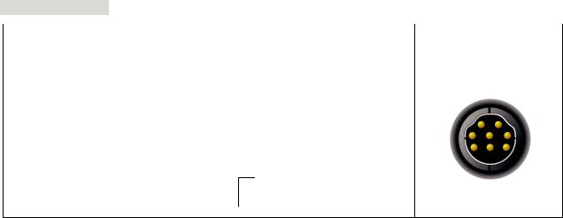
C. Connections (Connector Pinouts)
RS-232 Connection
|
DOP Series |
Controller |
|
Controller |
|
|
|
8 pin Mini DIN male |
|
||
|
9 pin D-SUB male (RS-232) |
8 pin Mini DIN male (RS-232) |
|
|
|
|
|
(RS-232) |
|
||
|
|
|
|
|
RXD (2) |
|
|
|
|
(7) TXD |
2 1 |
|
|
|
|
|
|
|||||
TXD (3) |
|
|
|
|
(4) RXD |
3 |
||
|
|
|
|
|||||
GND (5) |
|
|
|
(2) GND |
4 |
|||
|
|
|
7 |
6 |
||||
|
|
|
||||||
|
|
|
|
|
|
(3) RTS |
|
|
|
|
|
|
|
|
(6) CTS |
Top View |
|
|
|
|
|
|
|
|
|
|
|
|
|
|
|
|
|
|
|
1-16 |
Revision January, 2008, Doc. Name: 2007PDD23000007 |

Delta DOP Series HMI Connection Manual|DOP-A/AE/AS Series
AllenBradley SLC5 PLC |
Back to Table |
A. HMI factory setting
Baud rate: 19200, 8, None, 1.
PLC station number: 1.
Control area/status area: B3:0/B3:10.


 NOTE
NOTE
1) Error Check uses CRC (Cyclical Redundancy Check).
B. Definition of controller Read/Write address
Registers
|
|
|
Read/Write Range |
||
Register Type |
Format |
Word No. |
|
|
Bit No. |
Element No. |
Low Byte |
|
High Byte |
||
|
|
|
|||
|
|
|
|
Slot or File No. |
|
|
|
|
|
|
|
Output File |
O:n |
n: 0 ~ 30 |
N/A |
|
Slot No. s = 0 |
|
O:s.n |
|
|
|
s: 0 ~ 255 |
|
|
|
|
|
File No. = 0 |
|
|
|
|
|
|
Input File |
I:n |
n: 0 ~ 30 |
N/A |
|
Slot No. s = 0 |
|
I:s.n |
|
|
|
s: 0 ~ 255 |
|
|
|
|
|
File No. = 1 |
|
|
|
|
|
|
Status File |
S2:n |
n: 0 ~ 255 |
N/A |
|
File No. = 2 |
|
|
|
|
|
|
Bit File |
Bf:n |
n: 0 ~ 255 |
N/A |
|
f: 10 ~ 255 |
|
|
|
|
|
If f is ignored, file no. will be |
|
|
|
|
|
default setting 3. |
|
|
|
|
|
|
Timer Flag |
Tf:n |
n: 0 ~ 255 |
N/A |
|
f: 10 ~ 255 |
|
|
|
|
|
If f is ignored, file no. will be |
|
|
|
|
|
default setting 4. |
|
|
|
|
|
|
Timer Preset Value |
Tf:n.PRE |
n: 0 ~ 255 |
N/A |
|
f: 10 ~ 255 |
|
|
|
|
|
If f is ignored, file no. will be |
|
|
|
|
|
default setting 4. |
Timer Accumulator Value |
Tf:n.ACC |
n: 0 ~ 255 |
N/A |
|
f: 10 ~ 255 |
|
|
|
|
|
If f is ignored, file no. will be |
|
|
|
|
|
default setting 4. |
|
|
|
|
|
|
Counter Flag |
Cf:n |
n: 0 ~ 255 |
N/A |
|
f: 10 ~ 255 |
|
|
|
|
|
If f is ignored, file no. will be |
|
|
|
|
|
default setting 5. |
|
|
|
|
|
|
Counter Preset Value |
Cf:n.PRE |
n: 0 ~ 255 |
N/A |
|
f: 10 ~ 255 |
|
|
|
|
|
If f is ignored, file no. will be |
|
|
|
|
|
default setting 5. |
Revision January, 2008, Doc. Name: 2007PDD23000007 |
1-17 |

Delta DOP Series HMI Connection Manual|DOP-A/AE/AS Series
|
|
|
Read/Write Range |
||
Register Type |
Format |
Word No. |
|
|
Bit No. |
Element No. |
Low Byte |
|
High Byte |
||
|
|
|
|||
|
|
|
|
Slot or File No. |
|
|
|
|
|
|
|
Counter Accumulator Value |
Cf:n.ACC |
n: 0 ~ 255 |
N/A |
|
f: 10 ~ 255 |
|
|
|
|
|
If f is ignored, file no. will be |
|
|
|
|
|
default setting 5. |
|
|
|
|
|
|
Control File |
Rf:n |
n: 0 ~ 255 |
N/A |
|
f: 10 ~ 255 |
|
|
|
|
|
If f is ignored, file no. will be |
|
|
|
|
|
default setting 6. |
Control Size of Bit Array |
Rf:n.LEN |
n: 0 ~ 255 |
N/A |
|
f: 10 ~ 255 |
|
|
|
|
|
If f is ignored, file no. will be |
|
|
|
|
|
default setting 6. |
|
|
|
|
|
|
Control Reserved File |
Rf:n.POS |
n: 0 ~ 255 |
N/A |
|
f: 10 ~ 255 |
|
|
|
|
|
If f is ignored, file no. will be |
|
|
|
|
|
default setting 6. |
|
|
|
|
|
|
Integer File |
Nf:n |
n: 0 ~ 255 |
N/A |
|
f: 10 ~ 255 |
|
|
|
|
|
If f is ignored, file no. will be |
|
|
|
|
|
default setting 7. |
¾Bit No : Low byte is not used, so the value is 0. High byte stores file number.
Contacts
|
|
|
Read/Write Range |
||
Contact Type |
Format |
Word No. |
|
|
Bit No. |
Element No. |
Low Byte |
|
High Byte |
||
|
|
|
|||
|
|
Bits |
|
Slot or File No. |
|
|
|
|
|
||
Output |
O:n/b |
n: 0 ~ 30 |
b: 0 ~ 15 |
Slot No. s = 0 |
|
|
O:s.n/b |
|
|
|
s: 0 ~ 255 |
|
|
|
|
|
File No. = 0 |
|
|
|
|
|
|
Input |
I:n/b |
n: 0 ~ 30 |
b: 0 ~ 15 |
|
Slot No. |
|
I:s.n/b |
|
|
|
s = 0 |
|
|
|
|
|
s: 0 ~ 255 |
|
|
|
|
|
File No. = 1 |
|
|
|
|
|
|
Status |
S2:n/b |
n: 0 ~ 31 |
b: 0 ~ 15 |
|
2 |
|
|
|
|
|
|
Bit |
Bf:n/b |
n: 0 ~ 255 |
b: 0 ~ 15 |
|
f: 10 ~ 255 |
|
|
|
|
|
If f is ignored, file no. will be |
|
|
|
|
|
default setting 3. |
|
|
|
|
|
|
Timer |
Tf:n/b |
n: 0 ~ 255 |
b: 0 ~ 15 |
|
f: 10 ~ 255 |
|
Tf:n/EN |
n: 0 ~ 255 |
15 |
|
If f is ignored, file no. will be |
|
|
default setting 4. |
|||
|
Tf:n/TT |
n: 0 ~ 255 |
14 |
|
|
|
|
|
|||
|
Tf:n/DN |
n: 0 ~ 255 |
13 |
|
|
|
|
|
|
|
|
Timer Preset Value |
Tf:n.PRE/b |
n: 0 ~ 255 |
b: 0 ~ 15 |
|
f: 10 ~ 255 |
|
|
|
|
|
If f is ignored, file no. will be |
|
|
|
|
|
default setting 4. |
|
|
|
|
|
|
1-18 |
Revision January, 2008, Doc. Name: 2007PDD23000007 |

Delta DOP Series HMI Connection Manual|DOP-A/AE/AS Series
|
|
|
Read/Write Range |
||
Contact Type |
Format |
Word No. |
|
|
Bit No. |
Element No. |
Low Byte |
|
High Byte |
||
|
|
|
|||
|
|
Bits |
|
Slot or File No. |
|
|
|
|
|
||
Timer Accumulator Value |
Tf:n.ACC/b |
n: 0 ~ 255 |
b: 0 ~ 15 |
|
f: 10 ~ 255 |
|
|
|
|
|
If f is ignored, file no. will be |
|
|
|
|
|
default setting 4. |
|
|
|
|
|
|
Counter Flag |
Cf:n/b |
n: 0 ~ 255 |
b: 0 ~ 15 |
|
f: 10 ~ 255 |
|
Cf:n/CU |
n: 0 ~ 255 |
15 |
|
If f is ignored, file no. will be |
|
|
default setting 5. |
|||
|
Cf:n/CD |
n: 0 ~ 255 |
14 |
|
|
|
|
|
|||
|
Cf:n/DN |
n: 0 ~ 255 |
13 |
|
|
|
Cf:n/OV |
n: 0 ~ 255 |
12 |
|
|
|
Cf:n/UN |
n: 0 ~ 255 |
11 |
|
|
|
Cf:n/UA |
n: 0 ~ 255 |
10 |
|
|
|
|
|
|
|
|
Counter Preset Value |
Cf:n.PRE/b |
n: 0 ~ 255 |
b: 0 ~ 15 |
|
f: 10 ~ 255 |
|
|
|
|
|
If f is ignored, file no. will be |
|
|
|
|
|
default setting 5. |
Counter Accumulator Value |
Cf:n.ACC/b |
n: 0 ~ 255 |
b: 0 ~ 15 |
|
f: 10 ~ 255 |
|
|
|
|
|
If f is ignored, file no. will be |
|
|
|
|
|
default setting 5. |
|
|
|
|
|
|
Control |
Rf:n/b |
n: 0 ~ 255 |
b: 0 ~ 15 |
|
f: 10 ~ 255 |
|
Rf:n/EN |
n: 0 ~ 255 |
15 |
|
If f is ignored, file no. will be |
|
|
default setting 6. |
|||
|
Rf:n/DN |
n: 0 ~ 255 |
13 |
|
|
|
|
|
|||
|
Rf:n/ER |
n: 0 ~ 255 |
11 |
|
|
|
Rf:n/UL |
n: 0 ~ 255 |
10 |
|
|
|
Rf:n/IN |
n: 0 ~ 255 |
9 |
|
|
|
Rf:n/FD |
n: 0 ~ 255 |
8 |
|
|
|
|
|
|
|
|
Control Size of Bit Array |
Rf:n.LEN/b |
n: 0 ~ 255 |
b: 0 ~ 15 |
|
f: 10 ~ 255 |
|
|
|
|
|
If f is ignored, file no. will be |
|
|
|
|
|
default setting 6. |
|
|
|
|
|
|
Control Reserved |
Rf:n.POS/b |
n: 0 ~ 255 |
b: 0 ~ 15 |
|
f: 10 ~ 255 |
|
|
|
|
|
If f is ignored, file no. will be |
|
|
|
|
|
default setting 6. |
Integer |
Nf:n/b |
n: 0 ~ 255 |
b: 0 ~ 15 |
|
f: 10 ~ 255 |
|
|
|
|
|
If f is ignored, file no. will be |
|
|
|
|
|
default setting 7. |
|
|
|
|
|
|
¾Bit No : Low byte stores Bit address. High byte stores file number.


 NOTE
NOTE
1) Device O and I need to assign Slot No. (s). If not assign Slot No., it will use default setting 0.
Revision January, 2008, Doc. Name: 2007PDD23000007 |
1-19 |
Delta DOP Series HMI Connection Manual|DOP-A/AE/AS Series
C. Connections (Connector Pinouts)
RS-232
|
DOP series |
Controller |
|
Controller |
|
|
|
9 pin D-SUB female |
|
||
|
9 pin D-SUB male (RS-232) |
9 pin D-SUB female (RS-232) |
|
|
|
|
|
(RS-232) |
|
||
|
|
|
|
|
RXD (2) |
|
|
|
(3) TXD |
Pin1 |
|
|
||||
TXD (3) |
|
|
(2) RXD |
|
|
|
|
|
|||
GND (5) |
|
|
(5) SG |
|
|
|
|
|
|||
|
|
|
|
(7) RTS |
|
|
|
|
|
(8) CTS |
Top View |
|
|
|
|
|
|
1-20 |
Revision January, 2008, Doc. Name: 2007PDD23000007 |
|
Delta DOP Series HMI Connection Manual|DOP-A/AE/AS Series |
Cimon PLC (Loader Protocol) |
Back to Table |
A. HMI factory setting |
|
Baud rate: 38400, 8, None, 1, RS-232.
PLC station number: 1.
Control area/status area: D00000 / D00010.
B. Definition of controller Read/Write address
Registers
Register Type |
|
Format |
Read/Write Range |
|
Data Length |
||
|
Word No. |
Bit No. |
|
||||
|
|
|
|
|
|
||
Input |
Xn |
|
n: 000-512 |
N/A |
|
Word |
|
|
|
|
|
|
|
|
|
Output |
Yn |
|
n: 000-512 |
N/A |
|
Word |
|
|
|
|
|
|
|
|
|
General Purpose Relay |
Mn |
|
n: 000-999 |
N/A |
|
Word |
|
|
|
|
|
|
|
|
|
General Purpose Relay |
Ln |
|
n: 000-999 |
N/A |
|
Word |
|
|
|
|
|
|
|
|
|
Latch Relay |
Kn |
|
n: 000-999 |
N/A |
|
Word |
|
|
|
|
|
|
|
|
|
Flags |
Fn |
|
n: 000-127 |
N/A |
|
Word |
|
|
|
|
|
|
|
|
|
Timer (Set) |
TSn |
|
n: 0000-4095 |
N/A |
|
Word |
|
|
|
|
|
|
|
|
|
Timer (Current) |
TCn |
|
n: 0000-4095 |
N/A |
|
Word |
|
|
|
|
|
|
|
|
|
Counter (Set) |
CSn |
|
n: 0000-4095 |
N/A |
|
Word |
|
|
|
|
|
|
|
|
|
Counter (Current) |
CCn |
|
n: 0000-4095 |
N/A |
|
Word |
|
|
|
|
|
|
|
|
|
General Purpose Word Data |
Dn |
|
n:00000-31999 |
N/A |
|
Word |
|
|
|
|
|
|
|
|
|
Step Controller |
Sn |
|
n: 0-99 |
N/A |
|
Byte |
|
|
|
|
|
|
|
|
|
Contacts |
|
|
|
|
|
|
|
|
|
|
|
|
|
||
Contact Type |
|
Format |
Read/Write Range |
|
|
||
|
Word No. |
Bit No. |
|
|
|||
|
|
|
|
|
|||
Input |
Xnb |
|
n: 000-512 |
b: 0-F |
|
|
|
|
|
|
|
|
|
|
|
Output |
Ynb |
|
n: 000-512 |
b: 0-F |
|
|
|
|
|
|
|
|
|
|
|
General Purpose Relay |
Mnb |
|
n: 000-999 |
b: 0-F |
|
|
|
|
|
|
|
|
|
|
|
General Purpose Relay |
Lnb |
|
n: 000-999 |
b: 0-F |
|
|
|
|
|
|
|
|
|
|
|
Latch Relay |
Knb |
|
n: 000-999 |
b: 0-F |
|
|
|
|
|
|
|
|
|
|
|
Flags |
Fnb |
|
n: 000-127 |
b: 0-F |
|
|
|
|
|
|
|
|
|
|
|
Timer Status |
Tb |
|
N/A |
b: 0-4095 |
|
|
|
|
|
|
|
|
|
|
|
Counter Status |
Cb |
|
N/A |
b: 0-4095 |
|
|
|
|
|
|
|
|
|
|
|
Revision January, 2008, Doc. Name: 2007PDD23000007 |
1-21 |
Delta DOP Series HMI Connection Manual|DOP-A/AE/AS Series
C. Connections (Connector Pinouts)
RS-232
|
DOP series |
Controller |
|
Controller |
|
|
|
9 pin D-SUB female |
|
||
|
9 pin D-SUB male (RS-232) |
6 pin RJ11 |
|
|
|
|
|
(RS-232) |
|
||
|
|
|
|
|
RXD (2 ) |
2 |
|
|
TXD (3) |
3 |
1 ~ 6 |
|
GND (5) |
5 |
||
Top View |
|||
|
|


 NOTE
NOTE
1)Device S
The unit of PLC internal memory is byte and Device S is read by the unit of byte. Therefore, we recommend the user do not use two consecutive devices S as the read addresses or the interference will occur. For example, when choosing two numeric input device, please use S24 and S26, do not use S24 and S25.
1-22 |
Revision January, 2008, Doc. Name: 2007PDD23000007 |

|
Delta DOP Series HMI Connection Manual|DOP-A/AE/AS Series |
Copley Servo (Stepnet Protocol) |
Back to Table |
A. HMI factory setting |
|
Baud rate: 9600, 8, None, 1.
PLC station number: 0.
Control area/status area: None.
B. Definition of controller Read/Write address
Registers
Register Type |
Format |
Read/Write Range |
|
Data Length |
||
Word No. |
Bit No. |
|
||||
|
|
|
|
|
||
RAM memory |
Rn |
n: 00-FF (Hex) |
N/A |
|
DWord |
|
|
|
|
|
|
|
|
Flash memory |
Fn |
n: 00-FF (Hex) |
N/A |
|
DWord |
|
|
|
|
|
|
|
|
Internal Register |
IRn |
n: 0-31 |
N/A |
|
Word |
|
|
|
|
|
|
|
|
Contacts |
|
|
|
|
|
|
|
|
|
|
|
||
Contact Type |
Format |
Read/Write Range |
|
|
||
Word No. |
Bit No. |
|
|
|||
|
|
|
|
|||
BIT_DEVICE_RB |
RBn.b |
n: 00-FF (Hex) |
b: 0-31 |
|
|
|
|
|
|
|
|
|
|
BIT_DEVICE_FB |
FBn.b |
n: 00-FF (Hex) |
b: 0-31 |
|
|
|
|
|
|
|
|
|
|
BIT_DEVICE_T0 |
T0n |
N/A |
n: 0 |
|
|
|
|
|
|
|
|
|
|
BIT_DEVICE_T1 |
T1n |
N/A |
n: 0 |
|
|
|
|
|
|
|
|
|
|
BIT_DEVICE_T2 |
T2n |
N/A |
n: 0 |
|
|
|
|
|
|
|
|
|
|
BIT_DEVICE_RST |
RSTn |
N/A |
n: 0 |
|
|
|
|
|
|
|
|
|
|
BIT_DEVICE_CPR |
CPRn |
n: 00-FF (Hex) |
N/A |
|
|
|
|
|
|
|
|
|
|
BIT_DEVICE_CPF |
CPFn |
n: 00-FF (Hex) |
N/A |
|
|
|
|
|
|
|
|
|
|


 NOTE
NOTE
1)RB and FB are the bit access of Ram/Flash memory. Therefore, RB0x21.14 indicates bit 14 of Ram memory 0x21.
2)T0, T1 and T2 is virtual device for simulating Trajectory Generator Command. The number of 0, 1 and 2 indicates the subcommand of that command, so only bit 0 is acceptable.
3)RST is for simulating Reset Command, so only bit 0 is acceptable.
4)CPR and CPF are for simulating Copy Command of Ram and Flash individually. The address (n) after CPR and CPF is just the copy address for Ram/Flash memory. For example, CPRCA indicates that the content of Ram memory 0xCA will be copied into Flash memory 0xCA and CPFA6 indicates that the content of Flash memory 0xA6 will be copied into Ram memory 0xA6.
5)T0, T1, T2, RST, CPR, CPF are all write-only and they can not be used on Reset button.
Revision January, 2008, Doc. Name: 2007PDD23000007 |
1-23 |

Delta DOP Series HMI Connection Manual|DOP-A/AE/AS Series
C. Connections (Connector Pinouts)
RS-232
DOP series |
|
Controller |
|
9 pin D-SUB male (RS-232) |
|
9 pin D-SUB female (RS-232) |
|
RXD (2 ) |
|
|
RS-232 TxD |
|
|
||
TXD (3 ) |
|
|
RS-232 RxD |
|
|
||
GND (5) |
|
|
Signal Gro und |
|
|
||
|
|
|
|
1-24 |
Revision January, 2008, Doc. Name: 2007PDD23000007 |

Delta DOP Series HMI Connection Manual|DOP-A/AE/AS Series
Danfoss VLT 2800 (FC Protocol) |
Back to Table |
A. HMI factory setting
Baud rate: 9600, 8, Even, 1, RS-485.
PLC station number: 1.
Control area/status area: None / None.


 NOTE
NOTE
1)Delta HMI can be connected to for VLT-2800, 5000, 6000, 7000 controllers.
2)Each data length format of Danfoss AC drive parameter is not fixed, therefore, “Multiple Duplicate” function is not provided.
3)Max. supported alarm number is 16. If the alarm number is over 16, a fault will occur.
4)Does not support “optimum read/write” characteristic.
5)If the selected element is a string, the minimum data length should be more than 2.
B. Definition of controller Read/Write address
Registers
|
|
|
Read/Write Range |
||
Register Type |
Format |
Word No. |
|
|
Bit No. |
Low Byte |
|
High Byte |
|||
|
|
|
|||
|
|
|
|
|
Index No. |
Parameter |
Pn:I |
n: 0 ~ 999 |
0 |
|
I: 0 ~ 31 |
|
|
|
|
|
|
Control Word |
CTRWD |
0 |
N/A |
|
N/A |
|
|
|
|
|
|
Status Word |
STAWD |
0 |
N/A |
|
N/A |
|
|
|
|
|
|
¾Index No : If the index No. is not used, its default setting will be 0. The default setting of index No. for parameter P606 ~ P617 is 1.
¾Please notice that it is necessary to input the index No. when using some parameters of Danfoss controllers. At this time, please pay close attention on the setting range of index number. If the setting range is not started from 0, the parameter read & write failure will occur. For example, the index No. setting range of the parameter P615 is from 1 to 20, if the users do not input the index No., the system will assume the index number is 0 (default setting) and the a fault will occur when the users read or write the parameter.
¾CTRWD: Write-only. (Can not be used on the devices which can display the value or input value. It is recommended to be used on the setting value/setting constant (button), or marco function.)
¾STAWD: Read-only.
¾Control & Status Word: Please refer to the explanation on the next page.
Revision January, 2008, Doc. Name: 2007PDD23000007 |
1-25 |

Delta DOP Series HMI Connection Manual|DOP-A/AE/AS Series
Contacts
|
|
|
Read/Write Range |
||
Contact Type |
Format |
Word No. |
|
|
Bit No. |
Element No. |
Low Byte |
|
High Byte |
||
|
|
|
|||
|
|
Bits |
|
Index No. |
|
|
|
|
|
||
Parameter |
Pn:I.b |
n: 0 ~ 999 |
b: 0 ~ 31 |
|
I: 0 ~ 31 |
|
|
|
|
|
|
¾Bit No : Low byte stores Bit address. High byte stores index number.
C. Connections (Connector Pinouts)
|
RS-485 |
|
|
|
|
|
|
|
|
|
|
|
|
|
|
|
|
|
|
|
|
|
|
|
|
|
|
|
|
|
|
DOP Series |
|
|
|
|
|
|
Controller |
||
|
|
|
|
9 pin D-SUB male (RS-485) |
|
|
|
RS-485 cable connector |
|||||
|
|
|
|
RXD+ (2) |
|
|
|
|
|
|
68 TXD/RXD+ |
||
|
|
|
|
|
|
|
|
|
|||||
|
|
|
|
TXD+ (3 ) |
|
|
|
|
|
|
|||
|
|
|
|
|
|
|
|
|
|||||
|
|
|
|
|
|
|
|
||||||
|
|
|
|
RXD - (1 ) |
|
|
|
|
|
|
69 TXD/RXD - |
||
|
|
|
|
|
|
|
|
|
|||||
|
|
|
|
TXD- (4) |
|
|
|
|
|
|
|
|
|
|
|
|
|
|
|
|
|
|
|
|
|
||
|
|
|
|
|
|
|
|
|
|
|
|||
|
|
|
|
Shell |
|
Shell |
|||||||
|
|
|
|
||||||||||
|
|
|
|
|
|
|
|
|
|
|
|
||
|
Explanation of Control Word & Status Word |
|
|
||||||||||
|
|
|
|
|
|
|
|
|
|
|
|
|
|
|
Control Word |
|
|
|
|
|
|
|
|
||||
|
|
|
|
|
|
|
|
||||||
|
Bit |
|
Bit = 0 |
|
Bit = 1 |
|
|
||||||
|
15 |
|
No Function |
|
Reversing |
|
|
||||||
|
14 |
|
Choice of Setup 2 (msb) |
|
|
|
|
|
|
|
|
||
|
13 |
|
Choice of Setup 1 (lsb) |
|
|
|
|
|
|
|
|
||
|
12 |
|
No Function |
|
Relay 04 activated |
|
|||||||
|
11 |
|
No Function |
|
Relay 01 activated |
|
|||||||
|
10 |
|
Data Not Vaild |
|
Vaild |
|
|
||||||
|
9 |
|
Ramp 1 |
|
Ramp2 |
|
|
||||||
|
8 |
|
Jog 1 OFF |
|
ON |
|
|
||||||
|
7 |
|
No Function |
|
Reset |
|
|
||||||
|
6 |
|
Ramp Stop |
|
Start |
|
|
||||||
|
5 |
|
Hold |
|
Ramp Enable |
|
|
||||||
|
4 |
|
Quick-Stop |
|
Ramp |
|
|
||||||
|
3 |
|
Coasting |
|
Enable |
|
|
||||||
|
2 |
|
DC Brake |
|
Ramp |
|
|
||||||
|
1 |
|
Preset reference choice msb |
|
|
|
|
|
|
|
|
||
|
0 |
|
Preset reference choice msb |
|
|
|
|
|
|
|
|
||
|
|
|
|
|
|
|
|
|
|
|
|
|
|
¾When Bit 10 = 1 (Data Valid), the Control Word is valid.
1-26 |
Revision January, 2008, Doc. Name: 2007PDD23000007 |

Delta DOP Series HMI Connection Manual|DOP-A/AE/AS Series
Status Word
Bit |
Bit = 0 |
Bit = 1 |
|
15 |
Timer OK |
Above limit |
|
14 |
Torque OK |
Above limit |
|
13 |
Voltage OK |
Above limit |
|
12 |
Temperature OK |
Over-Temp, auto-start pending |
|
11 |
Not Running |
Running |
|
10 |
Out of Range |
Frequency OK |
|
9 |
Local Control |
Bus Control |
|
8 |
Speed ≠ reference |
Speed = reference |
|
7 |
No Warning |
Warning |
|
6 |
Reserved |
|
|
5 |
Reserved |
|
|
4 |
Reserved |
|
|
3 |
No Fault |
Trip |
|
2 |
Coasting |
Enabled |
|
1 |
VLT not ready |
Ready |
|
0 |
Control not ready |
Ready |
|
|
|
|
Revision January, 2008, Doc. Name: 2007PDD23000007 |
1-27 |

Delta DOP Series HMI Connection Manual|DOP-A/AE/AS Series
Emerson EC20 Series PLC Back to Table A. HMI factory setting
Baud rate: 19200, 8, Even, 1 (RS-232).
PLC station number: 0.
Control area/status area: D0 / D10.
B. Definition of controller Read/Write address
Registers
Register Type |
Format |
Read/Write Range |
|
Data Length |
||
Word No. |
Bit No. |
|
||||
|
|
|
|
|
||
Data Word |
Dn |
n: 0-7999 |
N/A |
|
Word |
|
|
|
|
|
|
|
|
Special Data Word |
SDn |
n: 0-255 |
N/A |
|
Word |
|
|
|
|
|
|
|
|
Data Word |
Zn |
n: 0-15 |
N/A |
|
Word |
|
|
|
|
|
|
|
|
Timer |
Tn |
n: 0-255 |
N/A |
|
Word |
|
|
|
|
|
|
|
|
Counter |
Cn |
n: 0-199 |
N/A |
|
Word |
|
|
|
|
|
|
|
|
DoubleWord Counter |
CDWn |
n: 200-255 |
N/A |
|
DWord |
|
|
|
|
|
|
|
|
DoubleWord Data Word |
DDWn |
n: 0-7998 |
N/A |
|
DWord |
|
|
|
|
|
|
|
|
Contacts |
|
|
|
|
|
|
|
|
|
|
|
||
Contact Type |
Format |
Read/Write Range |
|
|
||
Word No. |
Bit No. |
|
|
|||
|
|
|
|
|||
External Output Relay |
Yb |
N/A |
b: 0-377(Octal) |
|
||
|
|
|
|
|
||
External Input Relay |
Xb |
N/A |
b: 0-377(Octal) |
|
||
|
|
|
|
|
|
|
Internal Relay |
Mb |
N/A |
b: 0-1999 |
|
|
|
|
|
|
|
|
|
|
Special Internal Relay |
SMb |
N/A |
b: 0-255 |
|
|
|
|
|
|
|
|
|
|
Status Relay |
Sb |
N/A |
b: 0-991 |
|
|
|
|
|
|
|
|
|
|
Timer |
Tb |
N/A |
b: 0-255 |
|
|
|
|
|
|
|
|
|
|
Counter |
Cb |
N/A |
b: 0-255 |
|
|
|
|
|
|
|
|
|
|


 NOTE
NOTE
PLC Communication Settings:
1)Emerson EC20 series PLC has two communication ports, COM0 and COM1. They are provided for the communication protocol for connecting to PC, Modbus communication protocol and user-defined protocol. The default setting is COM0 to be enabled only, so the user needs to set the communication mode as Modbus RTU via PC software before using it.
2)COM1 supports RS-232 and RS-485.
1-28 |
Revision January, 2008, Doc. Name: 2007PDD23000007 |

Delta DOP Series HMI Connection Manual|DOP-A/AE/AS Series
3)Please note that not all of the addresses can be written when reading SM and SD device. We recommend the user not to set all of the addresses as write address except when setting parameters.
C. Connections (Connector Pinouts)
RS-232
|
|
DOP series |
|
|
Controller |
||||
|
|
9 pin D-SUB male (RS-232) |
|
|
COM1 |
||||
|
|
RXD (2 ) |
|
|
|
TXD |
|||
|
|
|
|
||||||
|
|
TXD (3 ) |
|
|
|
RXD |
|||
|
|
|
|
||||||
|
|
GND (5) |
|
|
|
GND |
|||
|
|
|
|
||||||
|
|
|
|
|
|
|
|
|
|
|
|
|
|
|
|
|
|
||
RS-485 |
|
|
|
||||||
|
|
|
|
|
|
|
|
|
|
|
|
DOP series |
|
|
Controller |
||||
|
|
9 pin D-SUB male (RS-232) |
|
|
COM1 |
||||
|
|
D- (1) |
|
|
|
|
(3) RS485+ |
||
|
|
|
|
|
|||||
|
|
D- (4) |
|
|
|
|
|
||
|
|
|
|
|
|
|
|||
|
|
|
|
|
|
|
|
||
|
|
|
|
|
|
|
|
||
|
|
D+ (2) |
|
|
|
|
(4) RS485- |
||
|
|
|
|
|
|||||
|
|
D+ (3) |
|
|
|
|
|
||
|
|
|
|
|
|
|
|||
|
|
|
|
|
|
|
|
||
|
|
|
|
|
|
|
|
||
|
|
G ND (5) |
|
|
GND |
||||
|
|
|
|
||||||
|
|
|
|
|
|
|
|
|
|
Revision January, 2008, Doc. Name: 2007PDD23000007 |
1-29 |
Loading...