


 Loading...

Preface
Thank you very much for purchasing DELTA’s DOP-A Series, DOP-AE Series and DOP-AS series Human Machine Interface (hereinafter “HMI” ) products.
This manual will be helpful in the installation, operation and specifications of Delta HMI product and HMI Screen Editor software program (hereinafter “ScrEdit” ). Before using the product, please read this user manual to ensure correct use.
You should thoroughly understand all safety precautions (DANGERS, WARNINGS and STOPS) before proceeding with the installation, wiring and operation. If you do not understand please contact your local Delta sales representative. Place this user manual in a safe location for future reference.
Using This Manual
Contents of this manual
zThis manual is a user guide that provides the information on how to install and operate Delta HMI products and ScrEdit.
Who should use this manual
This user manual is intended for the following users:
zThose who are responsible for designing.
zThose who are responsible for installing or wiring.
zThose who are responsible for operating or programming.
Important precautions
Before using the product, please read this user manual thoroughly to ensure correct use and store this manual in a safe and handy place for quick reference whenever necessary. Besides, please observe the following precautions:
zInstall the product in a clean and dry location free from corrosive and inflammable gases or liquids.
zEnsure that HMI is correctly connected to a ground. The grounding method must comply with the electrical standard of the country.
zDo not modify or remove wiring when power is applied to HMI.
zBefore starting the operation, make sure the emergency stop equipment can be energized and work at any time.
zDo not touch the power supply during operation. Otherwise, it may cause electric shock.
Revision Apr. 30th, 2007, 2007PDD23000002 |
i |
Preface|ScrEdit Software User Manual
This page intentionally left blank.
ii |
Revision Apr. 30th, 2007, 2007PDD23000002 |

Table of Contents
Preface |
........................................................................................................................................... |
|
i |
Chapter ...........................................................................................................1 |
Introduction |
1-1 |
|
1.1 ...................................................................................... |
DOP Series Human Machine Interface |
1-1 |
|
1.2 ..................................................................................................................................... |
Features |
1-1 |
|
1.3 ................................................................................................................... |
Ordering Information |
1-3 |
|
1.4 ....................................................................................................................................... |
Caution |
1-4 |
|
Chapter ...............................................................................2 Creating and Editing Screens |
2-1 |
||
2.1 .................................................................................................... |
ScrEdit (Screen Editor) Setup |
2-1 |
|
2.2 ................................................................................................................... |
How to Start ScrEdit |
2-5 |
|
2.3 ...................................................................................................... |
Menu Bar and Toolbar (File) |
2-12 |
|
2.4 ...................................................................................................... |
Menu Bar and Toolbar (Edit) |
2-23 |
|
2.5 .................................................................................................... |
Menu Bar and Toolbar (View) |
2-31 |
|
2.6 ............................................................................................... |
Menu Bar and Toolbar (Element) |
2-43 |
|
2.7 ................................................................................................. |
Menu Bar and Toolbar (Screen) |
2-52 |
|
2.8 ................................................................................................... |
Menu Bar and Toolbar (Tools) |
2-63 |
|
2.9 ................................................................................................ |
Menu Bar and Toolbar (Options) |
2-91 |
|
2.10 ............................................................................................... |
Menu Bar and Toolbar (Window) |
2-122 |
|
2.11 ..................................................................................................... |
Menu Bar and Toolbar (Help) |
2-126 |
|
Chapter .................................................................................................3 |
Element Function |
3-1 |
|
3.1 ............................................................................................................. |
How to Choose Element |
3-1 |
|
3.2 ........................................................................................................................... |
Button Element |
3-3 |
|
3.3 ............................................................................................................................ |
Meter Element |
3-19 |
|
3.4 ................................................................................................................................ |
Bar Element |
3-21 |
|
Revision Apr. 30th, 2007, 2007PDD23000002
Table of Contents|ScrEdit Software User Manual |
|
||
3.5 |
Pipe Element .............................................................................................................................. |
3-24 |
|
3.6 |
Pie Element ................................................................................................................................ |
3-27 |
|
3.7 |
Indicator...................................................................................................................................... |
3-29 |
|
3.8 |
Data Display ............................................................................................................................... |
3-32 |
|
3.9 |
Graph Display............................................................................................................................. |
3-38 |
|
3.10 |
Input Element ............................................................................................................................. |
3-46 |
|
3.11 |
Curve Element............................................................................................................................ |
3-52 |
|
3.12 |
Sampling Element ...................................................................................................................... |
3-60 |
|
3.13 |
Alarm Element ............................................................................................................................ |
3-68 |
|
3.14 |
Graphic Element......................................................................................................................... |
3-73 |
|
3.15 |
Keypad Element ......................................................................................................................... |
3-81 |
|
Chapter 4 |
Macro Function..................................................................................................... |
4-1 |
|
4.1 |
Macro Type................................................................................................................................. |
4-2 |
|
4.2 |
Macro Editing.............................................................................................................................. |
4-7 |
|
4.3 |
Macro Operation......................................................................................................................... |
4-14 |
|
4.4 |
Error Messages .......................................................................................................................... |
4-42 |
|
Chapter 5 Control Block and Status Block ............................................................................ |
5-1 |
||
5.1 |
Control Block .............................................................................................................................. |
5-2 |
|
5.2 |
Status Block................................................................................................................................ |
5-9 |
|
Chapter 6 |
Internal Memory ................................................................................................... |
6-1 |
|
Chapter 7 |
Example Explanation............................................................................................ |
7-1 |
|
Appendix A Specifications and Installation .............................................................................. |
A-1 |
||
A.1 |
Specifications ............................................................................................................................. |
A-1 |
|
A.2 |
Dimensions and Profile .............................................................................................................. |
A-5 |
|
A.3 |
Installation .................................................................................................................................. |
A-10 |
|
Revision Apr. 30th, 2007, 2007PDD23000002
Table of Contents|ScrEdit Software User Manual
Appendix B USB Flash Drive Function .................................................................................... |
B-1 |
Appendix C Main Menu Operation of HMI System .................................................................. |
C-1 |
Revision Apr. 30th, 2007, 2007PDD23000002
Table of Contents|ScrEdit Software User Manual
About this Manual…
User Information
Be sure to store this manual in a safe place.
Due to constantly growing product range, technical improvement and alteration or changed texts, figures and diagrams, we reserve the right of this manual contained information change without prior notice.
Coping or reproducing any part of this manual, without written consent of Delta Electronics Inc. is prohibited.
Technical Support and Service
Welcome to contact us or visit our web site (http://www.delta.com.tw/industrialautomation/) if you need any technical support, service and information, or, if you have any question in using the product. We are looking forward to serve you needs and willing to offer our best support and service to you. Reach us by the following ways.
ASIA
DELTA ELECTRONICS, INC.
TAOYUAN Plant/
31-1, SHIEN PAN ROAD, KUEI SAN INDUSTRIAL ZONE TAOYUAN 333, TAIWAN TEL: 886-3-362-6301
FAX: 886-3-362-7267
NORTH/SOUTH AMERICA
DELTA PRODUCTS CORPORATION
Sales Office/
P.O. BOX 12173 5101 DAVIS DRIVE,
RESEARCH TRIANGLE PARK, NC 27709, U.S.A. TEL: 1-919-767-3813
FAX: 1-919-767-3969
JAPAN
DELTA ELECTRONICS (JAPAN) INC.
Sales Office/
DELTA SHIBADAIMON BLDG. 2-1-14 SHIBADAIMON, MINATO-KU, TOKYO, 105-0012, JAPAN
TEL: 81-3-5733-1111
FAX: 81-3-5733-1211
EUROPE
DELTRONICS (NETHERLANDS) B.V.
Sales Office/
DE WITBOGT 15, 5652 AG EINDHOVEN, THE NETHERLANDS
TEL: 31-40-259-2860
FAX: 31-40-259-2851
Revision Apr. 30th, 2007, 2007PDD23000002

Chapter 1 Introduction
1.1DOP Series Human Machine Interface
DOP series HMI are manufactured by adopting high-speed hardware to provide you with a powerful programmable interface. ScrEdit software is a user-friendly program editor of DOP-A, DOP-AE and DOP-AS series HMI for Windows. Please refer to the following section for its features and function introduction.
1.2Features
PLC Serial Drives Support
DOP series HMI’s support more than twenty brands of PLC’s, including Delta, Omron, Siemens, Mitsubishi, etc. All of the newly supported PLC’s communication protocol information could be found on our website (http://www.delta.com.tw/industrialautomation/) for upgrade to meet your requirements. (All other trademarks in this manual are property of their respective companies.)
Windows® Fonts Support for ScrEdit Software
Except Simplified Chinese, traditional Chinese and English languages, ScrEdit software also provides those fonts that Windows® uses.
Quick Execution and Communication Macro
It can handle complicated calculation by executing macro. The user can also write communication protocol with communication macro command to connect specific system via COM port.
Rapid USB Upload/Download
It will shorten upload/download time by using USB Ver1.1.
Recipes
It provides useful recipe editor that is similar to Microsoft excel for user to edit recipe easily and input multiple recipes simultaneously (size limit is 64K). When downloading multiple recipes at the same time, it can exchange by internal memory of HMI. If data has finished editing when downloading, you can download recipe individually.
Direct Communication with Two or Three PLCs
DOP-A series HMI is able to connect to two different or the same controllers via two communication ports. Up to three communication ports are provided in DOP-AE and DOP-AS series HMI for direction connection to PLCs.
Revision Apr. 30th, 2007, 2007PDD23000002 |
1-1 |
Chapter 1 Introduction|ScrEdit Software User Manual
Support Multiple PLC’s Connections
One DOP series HMI can connect to multiple controllers in serial through COM2 of RS-485 port (NOTE 1).
Simulation Function (NOTE 2)
HMI ScrEdit software provides simulation feature which allows the user to develop and debug software on the PC connected to DOP series HMI before downloading it to DOP series HMI.
Off-line Simulation: When the editing and compile operation is completed, the user can use off-line simulation function to simulate HMI operation and check if it is correct or not through the PC directly without connecting to the controller.
On-line Simulation: When the editing and compile operation is completed, the user can use on-line simulation function to simulate HMI operation and check if it is correct or not through the PC directly with connecting to the controller.
Using SM Card to Backup Data
SM card can also be used to backup data or transfer data to another HMI. After data transmission, the data can be saved into the FLASH memory of HMI. History list and alarm message can be also saved in SM card and the user can read these files by card reader for collecting data and printing.
Multiple Security Protection
It provides passwords to protect designer’s intellectual property rights and also for the user to set the user’s priority for important components. Only the user, whose priority is higher than the component, can use the component.
USB Host Port (USB Host) Equipped
Parts of DOP series HMIs have a built-in USB Host interface for the connection to USB flash drive, card reader and printer with USB socket. The user can save data, copy program and print the screen immediately and increase the data storage space.
Multiple Security Protection
It provides passwords to protect designer’s intellectual property rights and also for user to set user priority for important component.
Multi-Language Support
It is easy for the user to switch the desired language via HMI or the external controller. Furthermore, Unicode editing is supported, and therefore it is convenient for the user to create and edit more quickly.
1-2 |
Revision Apr. 30th, 2007, 2007PDD23000002 |

Chapter 1 Introduction|ScrEdit Software User Manual


 NOTE
NOTE
1)The controller should provide RS-485 interface.
2)Off-line/On-line simulation functions are only provided for some parts of the controllers. Also, the execution time of on-line simulation only can continue 30 minutes. After the simulation time has finished, HMI will return ScrEdit software main screen from simulation window automatically.
3)When executing simulation function, the resolution of PC screen should be set to 24bit and higher, otherwise the simulation function may work abnormally.
1.3Ordering Information
|
DOP |
– |
AE |
10 |
TH |
T |
D |
– |
W |
|
1 |
|
2 |
3 |
4 |
5 |
6 |
|
7 |
|
|
|
|
|
|
|
|
||
1. |
Product Name |
Delta Operation Panel |
|
|
|
|
|
||
|
|
|
|
|
|
||||
2. |
Series |
AS: USB Client, USB Host, COM Port x 3 |
|
|
|
||||
|
|
A: USB Client, COM Port x 2 |
|
|
|
|
|
||
|
|
AE: USB Client, USB Host, COM Port x 3, Extension Port |
|
||||||
|
|
|
|
|
|
|
|
|
|
3. |
Panel Size |
38: 3.8 inches |
|
|
|
|
|
|
|
|
|
57: 5.7 inches |
|
|
|
|
|
|
|
|
|
75: 7.5 inches |
|
|
|
|
|
|
|
|
|
80: 8 inches |
|
|
|
|
|
|
|
|
|
94: 9.4 inches |
|
|
|
|
|
|
|
|
|
10: 10.4 inches |
|
|
|
|
|
|
|
|
|
|
|
|
|
|
|||
4. |
Panel Color and Type |
BS: Blue/White 16 Grays STN |
|
|
|
|
|||
|
|
GS: Black/White 16 Grays FSTN |
|
|
|
|
|||
|
|
CS: 256 Colors STN |
|
|
|
|
|
|
|
|
|
TC: 256 Colors TFT |
|
|
|
|
|
|
|
|
|
TH: 65536 Colors TFT |
|
|
|
|
|
||
|
|
|
|
|
|
|
|
|
|
5. |
Interface Type |
T: Touch Panel |
|
|
|
|
|
|
|
|
|
|
|
|
|
|
|
|
|
6. |
Input Power |
D: DC +24V |
|
|
|
|
|
|
|
|
|
|
|
|
|
|
|
|
|
7. |
Case Color |
None: Gray |
|
|
|
|
|
|
|
|
|
W: White (currently be provided for AS38, A57 and AE57 models only) |
|||||||
|
|
|
|
|
|
|
|
|
|
Revision Apr. 30th, 2007, 2007PDD23000002 |
1-3 |
Chapter 1 Introduction|ScrEdit Software User Manual
1.4Caution
Operation Environment (temperature and humidity)
HMI should be operated in the following environment parameters to adjust screen brightness and contrast to get the best image. If operating out of the range, LCD may be improperly displayed when using for long time.
Ambient Operating Temperature: 0 ºC to 50 ºC (32 ºF to 122 ºF) Relative Humidity: 10% ~ 90%, no condensation allowed
SM Card
SM card can be used to save and transmit data. Only SM card that formatted by HMI can be used on both HMI and Windows® OS system. (Even it can be read/written in some format, but faults may occur due to different format among Win95/98/2000/XP versions)
USB Flash Drive
USB flash drive can be used to save data. It also can be used to copy data from HMI and its format is FAT32. When using USB flash drive to save data, we recommend the user should enter system screen first and then remove the USB flash drive. Follow this process can ensure that the data is saved completely in USB flash drive.
1-4 |
Revision Apr. 30th, 2007, 2007PDD23000002 |

Chapter 2 Creating and Editing Screens
2.1ScrEdit (Screen Editor) Setup
In this chapter, it will introduce general functions of Screen Editor with Windows. The user can use it to design what he wants. Detail information for each function will be discussed in following chapters.
Minimum System Requirement
Below are the system requirements to comply with the operation environment of ScrEdit:
|
|
|
|
|
Item |
|
System Requirement |
|
|
|
|
|
CPU |
|
Pentium III, 500MHz or greater is recommended |
|
|
|
|
|
Memory |
|
256MB and above is recommended |
|
|
|
|
|
Hard Disk |
|
Capacity: 400MB and above |
|
|
|
|
|
Monitor |
|
Support resolution: 800 × 600 or higher full-color display. |
|
|
|
|
|
|
|
|
|
Printer |
|
Printer compatible with Windows® 2000 & Windows® XP |
|
|
|
|
|
Operation System |
|
Windows® 2000 & Windows® XP |
|
|
|
|
Software installation
The user can download the Screen Editor, the program editor of Delta HMI product via the link below: http://www.delta.com.tw/product/em/hmi/hmi_software.asp.
To start the Delta HMI ScrEdit setup, please refer to the following steps:
1. Step 1: Please start-up your computer to Win2000/WinXP system (Fig. 2.1.1).
Fig. 2.1.1 Open Microsoft Windows
Revision Apr. 30th, 2007, 2007PDD23000002 |
2-1 |

Chapter 2 Creating and Editing Screens|ScrEdit Software User Manual
2.Step 2: Execute setup.exe from Windows taskbar by clicking “Start” > “Run”. 3. After pressing OK, system will setup automatically and you will get the following dialog box to select the desired display language (Fig. 2.1.2).
Fig. 2.1.2 Select Language
After pressing OK, system will setup automatically and you will get the following dialog box to choose destination location (Fig. 2.1.3).
Fig. 2.1.3 Directory for installing ScrEdit
To select the default directory C: \Program File\Delta\Screen Editor 1.05.XX\, click Next> for the next step. Setup will install in the directory indicated in the Destination Directory box at the bottom of the dialog box.
2-2 |
Revision Apr. 30th, 2007, 2007PDD23000002 |

Chapter 2 Creating and Editing Screens|ScrEdit Software User Manual
To select a directory other than the default directory, click Browse. A list of available directories appears. Highlight the desired directory for the Delta HMI ScrEdit and click OK, then Next> for the next step.
If necessary, click < Back button to take you back through Setup dialog boxes one by one.
3.Step 3: After pressing Next, system will ask you to select the installation software, i.e. ScrEdit (Fig. 2.1.4).
Fig. 2.1.4 Select ScrEdit
4. Step 4: Then click Install button to start ScrEdit installation (Fig. 2.1.5).
Fig. 2.1.5 Starting ScrEdit installation
Revision Apr. 30th, 2007, 2007PDD23000002 |
2-3 |
Chapter 2 Creating and Editing Screens|ScrEdit Software User Manual
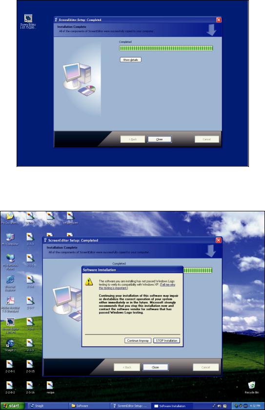
Fig. 2.1.6 Finish installing ScrEdit
5.Step 5: After finish installing ScrEdit (Fig. 2.1.6), system will ask you to install HMI USB driver, please click Yes to install.
Fig. 2.1.7 Install HMI USB driver
6. Step 6: After installing HMI USB driver, click Close to complete the installation.
2-4 |
Revision Apr. 30th, 2007, 2007PDD23000002 |

Chapter 2 Creating and Editing Screens|ScrEdit Software User Manual
2.2How to Start ScrEdit
1.After setup, you can start ScrEdit by clicking Screen Editor 1.05.XX shortcut on the desk (Refer to Fig. 2.2.1) or from Windows taskbar, click Start > Programs > Delta > Screen Editor 1.05.XX.
Fig. 2.2.1
Fig. 2.2.2 Start-up display
Revision Apr. 30th, 2007, 2007PDD23000002 |
2-5 |
Chapter 2 Creating and Editing Screens|ScrEdit Software User Manual
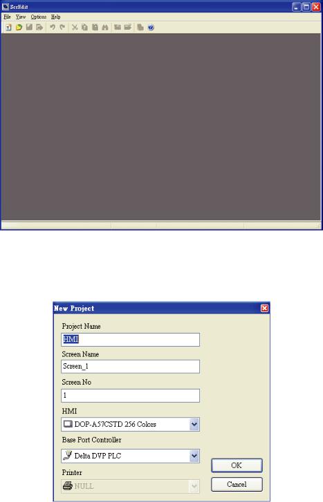
When ScrEdit is activated for the first time, the first window to show up is as follows. There are only File (F), View(V), Option(O) and Help(H) on the toolbar.
Fig. 2.2.3 Screen without editing file
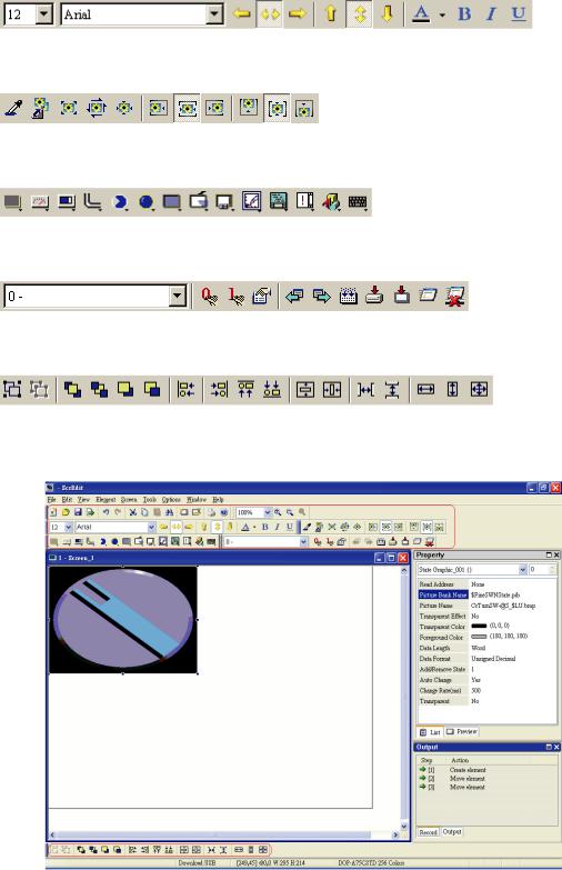
2.After pressing  or click File > New, it can create a new project and you will get a dialog box as shown in the following. (Fig. 2.2.4)
Fig. 2.2.4 Creating a New project
3.Enter the Project Name, Screen Name, Screen No. and select connected HMI, controller or printer. Then, click OK. It can create a new project in ScrEdit as shown in the following. (Fig. 2.2.5)
2-6 |
Revision Apr. 30th, 2007, 2007PDD23000002 |

Chapter 2 Creating and Editing Screens|ScrEdit Software User Manual
Fig. 2.2.5 New project screen of ScrEdit
There are five parts in the following for ScrEdit editing window.
Menu Bar
There are nine functions for selection: File, Edit, View, Element, Screen, Tools, Options, Window, and Help.
Toolbar
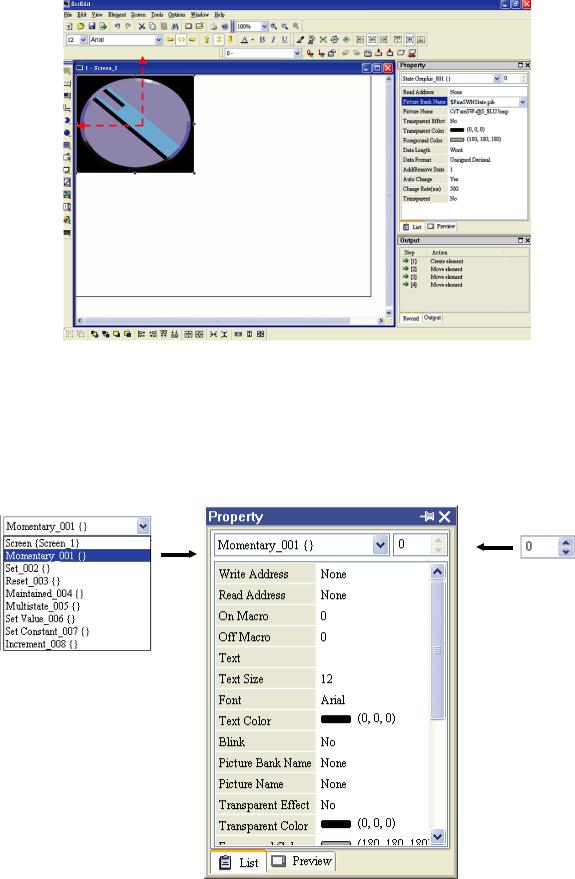
Toolbar (Fig. 2.2.6) is like those toolbar in Windows® program. It is easy to use for editing and the user can arrange its position freely. For example, the user can move the Toolbar to the left side of the screen. Also, the user can arrange the toolbar position by their usage. The followings are the available toolbar on ScrEdit.
1.Standard Toolbar
2.Zoom Toolbar
Revision Apr. 30th, 2007, 2007PDD23000002 |
2-7 |
Chapter 2 Creating and Editing Screens|ScrEdit Software User Manual
3.Text Format Toolbar
4.Bitmap Toolbar
5.Element Toolbar
6.Build Toolbar
7.Layout Toolbar
Fig. 2.2.6 ScrEdit Toolbar
2-8 |
Revision Apr. 30th, 2007, 2007PDD23000002 |
Chapter 2 Creating and Editing Screens|ScrEdit Software User Manual
Fig. 2.2.7 Move ScrEdit toolbar to the left side of the screen
Property Table
It provides element property settings for each element (Fig. 2.2.8 & Fig. 2.2.9). Please refer to Chapter 3 for detailed description.
Element state selection
All elements on current editing screen
Fig. 2.2.8 Property table
Revision Apr. 30th, 2007, 2007PDD23000002 |
2-9 |
Chapter 2 Creating and Editing Screens|ScrEdit Software User Manual
Fig. 2.2.9 Editing screen preview
Output Window
All editing actions and output message when compile function is enabled will be shown here (Fig. 2.2.10). When compiling, ScrEdit will detect the error of user program automatically. Once error occurs, the correspondent message will display in output window. Click error message to get error element window.
Fig. 2.2.10 Output window
2-10 |
Revision Apr. 30th, 2007, 2007PDD23000002 |

Chapter 2 Creating and Editing Screens|ScrEdit Software User Manual
Work Place
Following is an editing example display (Fig. 2.2.11).
Fig. 2.2.11 ScrEdit Work Place
Revision Apr. 30th, 2007, 2007PDD23000002 |
2-11 |
Chapter 2 Creating and Editing Screens|ScrEdit Software User Manual
2.3Menu Bar and Toolbar (File)
ScrEdit provides the convenient pull-down Menu and makes it easy for the user to create, edit and manage includes elements, pictures, graphs, macro program, recipes and displays in DOP series HMI. The pull-down menu options of Menu bar are described as follows:
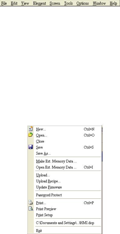
File
The “File” menu performs many common functions.
1.Allows user to create new project, open old project, close file, save current file and save current file to another file name, etc. options.
2.Make and Open external memory data (Ext. Memory Data).
3.Upload the editing display and data of DOP series HMI to PC and save to hard disk.
4.Update the firmware of DOP series HMI.
5.Password protection function.
6.Screen print, print preview and print setup functions.
7.By default, ScrEdit presents a list of the most recent used files on the File menu for quick access. Just click the file name to open the file.
8.Exit command is to close all open editing files and offer to save those which have not been save yet and finally exit the ScrEdit.
Fig. 2.3.1 File options
2-12 |
Revision Apr. 30th, 2007, 2007PDD23000002 |
Chapter 2 Creating and Editing Screens|ScrEdit Software User Manual
Create a New Project
Creates a new project by choosing File > New (Fig. 2.3.2) or clicking the New icon  from toolbar (Fig. 2.3.3), or using keyboard shortcuts by pressing Ctrl + N.
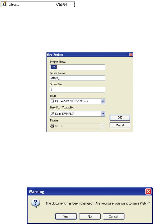
1.If this is the first time use and there is no old project, the following dialog box (Fig. 2.3.2) will show up for the user to input project name, screen name, screen number, HMI type and connecting base port controller after creating a new project.
Fig. 2.3.2 New project dialog box
2.If other project files already exist and are open, the user will get the following dialog box to remind the user of saving project (Fig. 2.3.3) before creating new project. Press Yes button to save the existed file, press No button not to save the file and press Cancel button to cancel the save operation. After the user press the Yes or No button, the new project dialog box will appear again (Fig. 2.3.2).
Fig. 2.3.3 Saving dialog box
3.Input project name, screen name, select HMI model and connecting base port controller (Fig. 2.3.4), and then press OK button.
Revision Apr. 30th, 2007, 2007PDD23000002 |
2-13 |

Chapter 2 Creating and Editing Screens|ScrEdit Software User Manual
Fig. 2.3.4 HMI model and base port controller options
Open Old Project
Open current project by choosing File > Open (Fig. 2.3.7) or clicking the Open icon  from toolbar, or using keyboard shortcuts by pressing Ctrl + O.
1.If other project files exist before opening an old project, the user will get the Saving dialog box (Fig. 2.3.3) to remind the user of saving file and then get the following dialog box for opening existing dop file (Fig. 2.3.5).
2.If save operation is complete or there is no old project files, the following dialog box for opening existing dop file (Fig. 2.3.5) will show up directly.
Fig. 2.3.5 Open an old project in ScrEdit
2-14 |
Revision Apr. 30th, 2007, 2007PDD23000002 |

Chapter 2 Creating and Editing Screens|ScrEdit Software User Manual
Close File
Closes project by clicking File > Close (Fig. 2.3.10).
1.If project didn’t get saved before issuing the command of closing project, the user will get saving dialog box (Fig. 2.3.6) to remind the user of saving project.
Fig. 2.3.6 Saving dialog box
Save File
Save current project into hard disk with extension file “dop” by choosing File > Save (Fig. 2.3.12) or
clicking the Save icon  (Fig. 2.3.13), or using keyboard shortcuts by pressing Ctrl + S. If the project is a new file, the Save as dialog box will show up (Fig. 2.3.15). If the project is an old file, the Save function will perform immediately and the Save as dialog box will not show up.
Save As
Save current project to another file name by clicking File > Save As (Fig. 2.3.14). The user will get Save as dialog box (Fig. 2.3.15) to input project name with extension file dop. This dialog also appears automatically when the first time any project file is saved no matter whether Save As or Save command is used.
Revision Apr. 30th, 2007, 2007PDD23000002 |
2-15 |

Chapter 2 Creating and Editing Screens|ScrEdit Software User Manual
Fig. 2.3.7 Save as dialog box (Dialog box that let user input project name to save as.)
Make Ext. Memory Data
Before using this command, ensure to compile the editing screen data. If not execute the compilation first, the ScrEdit cannot make screen data and an error message dialog box will show up (Fig. 2.3.8). Please execute the compilation first and then clicking File > Make Ext. Memory Data to copy the compiled HMI program into SM card (Fig. 2.3.9) or a USB flash drive. If the SM card or USB flash drive with compiled HMI program stored inside is inserted into HMI, HMI will startup by reading the data of SM card or USB flash drive directly.
Fig. 2.3.8 Error message dialog box when making Ext. Memory Data
Fig. 2.3.9 Make Ext. Memory Data Dialog Box
2-16 |
Revision Apr. 30th, 2007, 2007PDD23000002 |

Chapter 2 Creating and Editing Screens|ScrEdit Software User Manual
Open Ext. Memory Data
In HMI, the user can move the screen data saved in the flash memory into SM card through folder manager. Then, perform Open Ext. Memory Data function and the user will get the user will get Fig. 2.3.9 dialog box. At this time, the user can open the screen data and edit the HMI screen data directly.
Upload Screen Data and Recipe
After clicking File > Upload, the password dialog box will show up first (Fig. 2.3.10), the user needs to input password (the password is the highest priority saved in HMI, which is set by clicking Options > Configuration > Standard > Security). When entering the correct password, the user can get save as dialog box (Fig. 2.3.7). After inputting project file name, the uploading will start (Fig. 2.3.11). The user can get the progress with progress box and stop uploading by clicking Stop button. When progress goes to 100%, it indicates that the uploading is complete. The user can press Stop button to exit the dialog box. The file that is uploaded from HMI can be restored to original editing file for user to edit. This option is to avoid losing the original editing file. If the user wants to upload data with pictures also, just select the “Include Picture Data when uploading” in Environment dialog box by clicking Options >
Environment.
Fig. 2.3.10 Enter password dialog box
Fig. 2.3.11 Uploading screen
Revision Apr. 30th, 2007, 2007PDD23000002 |
2-17 |

Chapter 2 Creating and Editing Screens|ScrEdit Software User Manual
Fig. 2.3.12 Environment dialog box
Upload Recipe
This function is similar to upload function but it can only upload recipe. Before uploading, it also needs to enter password (the password is the highest priority saved in HMI, which is set by clicking Options >
Configuration > Standard > Security).
Update Firmware
This option is for upgrading HMI firmware or adding function for HMI (Fig. 2.3.13). Keeping HMI firmware version to be the most updated version can optimize HMI operation. Ensure that the software version of ScrEdit matches the firmware version. The user can get the firmware information by clicking Tools > Get Firmware Information. Regarding the software version of ScrEdit, the user can find it by clicking Help > About ScrEdit (Fig. 2.3.14).
Fig. 2.3.13 Choosing Update Firmware command from menu bar
2-18 |
Revision Apr. 30th, 2007, 2007PDD23000002 |
Chapter 2 Creating and Editing Screens|ScrEdit Software User Manual
Fig. 2.3.14 About ScrEdit
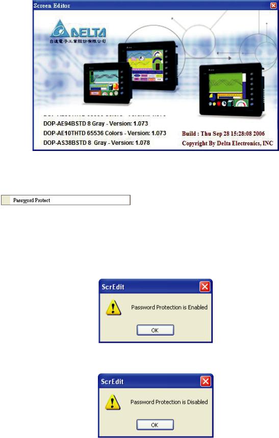
Password Protect
The user can enable and disable password protect function (Fig. 2.3.15 & Fig. 2.3.16) by clicking File > Password protect. Once password protect function is enabled, the user will get Fig. 2.3.15 dialog box
and  symbol before “Password Protect” command. If the
  symbol shows before “Password Protect” command from File menu, it indicates that this dop file is password protected and the user will need to input password before opening dop file. The password is set by clicking Options > Configuration > Standard > Security) (Fig. 2.3.17). If the password protect function is disabled, the Fig. 2.3.16 dialog box will show up.
Fig. 2.3.15 Password protect function is enabled
Fig. 2.3.16 Password protect function is disabled
Revision Apr. 30th, 2007, 2007PDD23000002 |
2-19 |
Loading...