


5011665702
2008-12-30
HB02
Preface
Thank you for purchasing DELTA’s DOP-B series. This quick start will be helpful in the installation, wiring and inspection of Delta HMI. Before using the product, please read this quick start to ensure correct use. You should thoroughly understand all safety precautions before proceeding with the installation, wiring and operation. Place this quick start in a safe location for future reference. Please observe the following precautions:
Install the product in a clean and dry location free from corrosive and inflammable gases or liquids.
Ensure that all wiring instructions and recommendations are followed.
Ensure that HMI is correctly connected to a ground. The grounding method must comply with the electrical standard of the country (Please refer to NFPA 70: National Electrical Code, 2005 Ed.).
Do not modify or remove wiring when power is applied to HMI.
Do not touch the power supply during operation. Otherwise, it may cause electric shock.
For the information of HMI software operation, and software installation, please refer to the HMI software manual.
If you have any questions during operation, please contact our local distributors or Delta sales representative.
The content of this quick start may be revised without prior notice. Please consult our distributors or download the most updated version at http://www.delta.com.tw/industrialautomation.
Safety Precautions
Carefully note and observe the following safety precautions when receiving, inspecting, installing, operating, maintaining and troubleshooting. The following words, DANGER, WARNING and STOP are used to mark safety precautions when using the Delta’s HMI product. Failure to observe these precautions may void the warranty!
Installation
Comply with quick start for installation. Otherwise it may cause equipment damage.
Do not install the product in a location that is outside the stated specification for the HMI. Failure to observe this caution may result in electric shock, fire, or personal injury.
Wiring
Connect the ground terminals to a class-3 ground (Ground resistance should not exceed 100Ω). Improper grounding may result in communication error, electric shock or fire.
Operation
The users should use Delta Screen Editor software to perform editing in Delta's HMI product. To perform editing and confirming HMI programs without using Delta Screen Editor software in Delta's HMI product may result in abnormal operation.
Do not modify wiring during operation. Otherwise it may result in electric shock or personal injury.
Never use a hard or pointed object to hit or strike the screen as doing this may damage the screen and let the screen has not respond at all, and then cause HMI to work abnormally.
English-1

Maintenance and Inspection
Do not touch any internal or exposed parts of the HMI as electrical shock may result.
Do not remove operation panel while power is on. Otherwise electrical shock may result.
Wait at least 10 minutes after power has been removed before touching any HMI terminals or performing any wiring and/or inspection as an electrical charge may still remain in the HMI with hazardous voltages even after power has been removed.
Turn the power off before changing backup battery and check system settings after finishing change. (all data will be cleared after changing battery).
Be sure the ventilation holes are not obstructed during operation. Otherwise malfunction may result due to bad ventilation or overheating troubles.
Wiring Method
Remove the terminal block from the HMI before wiring.
Insert only one wire into one terminal on the terminal block.
If the wiring is in error, perform the wiring again with proper tools. Never use force to remove the terminals or wires. Otherwise, it may result in malfunction or damage.
For the power line that forced to take out, ensure to check wiring again and restart.
Communication Wiring
Comply with communication wiring specification for wiring.
Wiring length should comply with the stated specification for the HMI.Proper grounding to avoid bad communication quality.
Installation and Storage Conditions
The product should be kept in the shipping carton before installation. In order to retain the warranty coverage, the HMI should be stored properly when it is not to be used for an extended period of time. Some storage suggestions are:
Store in a clean and dry location free from direct sunlight.
Store within an ambient temperature range of -20°C to +60°C (-4°F to 140°F).
Store within a relative humidity range of 10% to 90% and non-condensing.
Do not store the HMI in a place subjected to corrosive gases and liquids.
Correctly packaged and placed on a solid and durable surface.
Do not mount the HMI adjacent to heat-radiating elements or in direct sunlight.
Do not mount the HMI in a location subjected to corrosive gases, liquids, or airborne dust or metallic particles.
Do not mount the HMI in a location where temperatures and humidity will exceed specification.
Do not mount the HMI in a location where vibration and shock will exceed specification.
Do not mount the HMI in a location where it will be subjected to high levels of electromagnetic radiation.
Installation
Installation Note:
Improper installation will result in malfunction and greatly reduce the life of the HMI. Be sure to follow the guidelines in this quick start when installing the HMI.
In order to ensure the HMI being well ventilated, make sure that the ventilation holes are not obstructed and must provide sufficient free space around HMI.
English-2
For use on a flat surface of a Type 4X "Indoor Use Only" enclosure or equivalent.
The allowable thickness of the panel for mounting should be less than 5 mm.
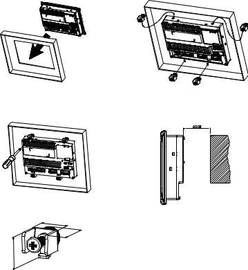
Installation Method:
Step 1:
Ensure to put waterproof gasket into HMI and then insert the HMI into the panel cutout.
Step 2:
Ensure to insert fasteners into the HMI’s insertion slots and turn the screw till screws touch panel cutout.
Step 3:
Turn the screw with less than torque 0.7N.M to avoid damage to plastic box.
Torque: 6.17lb-inch (0.7N-M)
The size of the fastener.
16
|
.4 |
0 |
|
2 |
|
16.3
Units: mm
Step 4:
Keep at least 60mm distance from rear of HMI product to the wall, installation surface or the other controllers for heat dissipation.
Units: mm
Wiring
Recommended wiring is in the table below:
Type |
Wire Gauge (AWG) |
Stripped length |
Torque |
Solid |
28 ~ 12 |
7 ~ 8 mm |
5 kg-cm (4.3 lb-in) |
Stranded |
30 ~ 12 |
7 ~ 8 mm |
5 kg-cm (4.3 lb-in) |
English-3
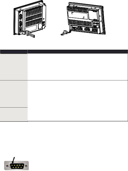
Be sure to plug power line into HMI according to following arrow direction.
DOP-B05S100
DOP-B07S200 DOP-B07S201 DOP-B07S211 DOP-B07E205 DOP-B07E215
Basic Inspection
Item
General Inspection
Inspection before operation (power is not applied)
Inspection before operation (power is applied)
Content
Periodically inspect the screws of the connection between the HMI and device. Tighten screws as necessary as they may loosen due to vibration and varying temperatures.
Ensure that oil, water, metallic particles or any foreign objects do not fall inside the HMI, control panel or ventilation slots and holes. As these will cause damage.
Ensure the correct installation and the control panel. It should be free from airborne dust, harmful gases or liquids.
Ensure that all wiring terminals are correctly insulated.
Ensure that all wiring is correct or damage and or malfunction may result.Visually check to ensure that there are not any unused screws, metal
strips, any conductive or inflammable materials inside HMI.
Ensure to lower electromagnetic interference when devices are influenced by it.
Ensure that the external applied voltage to HMI is correct and matched to the controller.
Check if power LED lights.
Check if the communication among devices is normal.
Please contact our local distributors or Delta sales representative if there are any abnormal conditions.
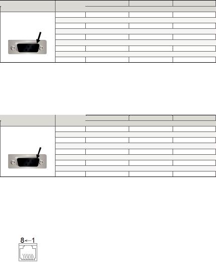
Pin Definition of Serial Communication
DOP-B07 Series
COM1 Port (Supports Flow Control)
COM Port |
|
PIN |
Contact |
|
RS-232 |
||
|
|
|
|
|
|
1 |
|
PIN1 |
|
2 |
RXD |
|
3 |
TXD |
|
|
|
||
|
|
4 |
|
|
|
5 |
GND |
|
|
6 |
|
|
|
7 |
RTS |
|
|
8 |
CTS |
|
|
9 |
|
Note: Blank = No Connection. |
|
|
|
|
|
|
English-4 |
COM2 Port (Supports Flow Control)
COM Port |
PIN |
MODE1 |
MODE2 |
MODE3 |
|
RS-232 |
RS-422 |
RS-485 |
|||
|
|
||||
|
1 |
|
TXD+ |
D+ |
|
|
2 |
RXD |
|
|
|
PIN1 |
3 |
TXD |
|
|
|
4 |
|
RXD+ |
|
||
|
|
|
|||
|
5 |
GND |
GND |
GND |
|
|
6 |
|
TXD- |
D- |
|
|
7 |
RTS |
|
|
|
|
8 |
CTS |
|
|
|
|
9 |
|
RXD- |
|
Note1: Blank = No Connection.
Note2: When COM2 port is used for RS-232 flow control, i.e. RTS and CTS signals are used for flow control, COM3 port will become incapable of being used.
Note3: When COM2 port is used for RS-422 flow control, please refer to the following COM3 Port signals table for pin assignments. The signals, RTS+, CTS+, RTSand CTSshown in brackets are the signals used for flow control.
COM3 Port
COM Port |
PIN |
MODE1 |
MODE2 |
MODE3 |
|
RS-232 |
RS-422 |
RS-485 |
|||
|
|
||||
|
1 |
|
TXD+(RTS+) |
D+ |
|
|
2 |
RXD |
|
|
|
PIN1 |
3 |
TXD |
|
|
|
4 |
|
RXD+(CTS+) |
|
||
|
5 |
GND |
GND |
GND |
|
|
6 |
|
TXD-(RTS-) |
D- |
|
|
7 |
|
|
|
|
|
8 |
|
|
|
|
|
9 |
|
RXD-(CTS-) |
|
Note1: Blank = No Connection.
Note2: When COM2 port is used for RS-422 flow control, please refer to the COM3 Port signals table above for pin assignments. The signals, RTS+, CTS+, RTSand CTSshown in brackets are the signals used for flow control.
Ethernet Interface (LAN)
Ethernet Interface (LAN) |
|
PIN |
Contact |
|
Ethernet |
||
|
|
|
|
|
|
1 |
TX+ |
|
|
2 |
TX- |
|
|
3 |
RX+ |
|
|
4 |
|
|
|
5 |
|
|
|
6 |
RX- |
|
|
7 |
|
|
|
8 |
|
Note: Blank = No Connection. |
|
|
|
English-5

DOP-B05 Series
COM1 Port (Supports Flow Control) |
|
||
|
|
|
|
COM Port |
PIN |
Contact |
|
RS-232 |
|||
|
|
||
|
1 |
|
|
PIN1 |
2 |
RXD |
|
|
3 |
TXD |
|
|
4 |
|
|
|
5 |
GND |
|
|
6 |
|
|
|
7 |
RTS |
|
|
8 |
CTS |
|
|
9 |
|
|
Note: Blank = No Connection.
COM2 and COM3 Port
COM Port |
PIN |
MODE1 |
MODE2 |
MODE3 |
|||
COM2 |
COM3 |
COM2 |
COM3 |
COM2 |
COM3 |
||
|
|
RS-232 |
RS-485 |
RS-485 |
RS-485 |
RS-232 |
RS-422 |
|
1 |
|
|
D+ |
|
|
TXD+ |
|
2 |
RXD |
|
|
|
RXD |
|
PIN1 |
3 |
TXD |
|
|
|
TXD |
|
4 |
|
D+ |
|
D+ |
|
RXD+ |
|
|
|
|
|
||||
|
5 |
GND |
GND |
GND |
|||
|
6 |
|
|
D- |
|
|
TXD- |
|
7 |
|
|
|
|
|
|
|
8 |
|
|
|
|
|
|
|
9 |
|
D- |
|
D- |
|
RXD- |
Note: Blank = No Connection.
English-6
Parts Names
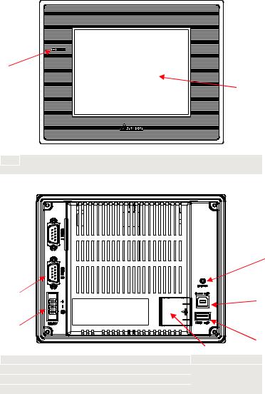
DOP-B05S100 (Front View)
A
B
APower LED Indicator (Lights in green when HMI works normally.)
BTouch Screen / Display
DOP-B05S100 (Rear View)
C 
G
|
B |
|
F |
|
|
|
|
|
A |
|
|
|
|
|
E |
|
|
|
D |
A |
Power Input Terminal |
E |
USB Host |
B |
COM2 (RS-232 / RS-422 / RS-485) |
F |
USB Client |
C |
COM1 (RS-232) |
G |
System Key |
D |
Battery Cover |
|
|
English-7
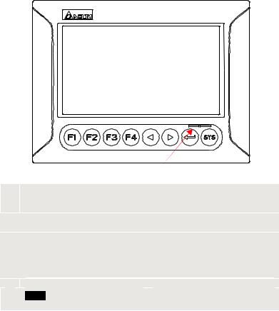
DOP-B07S200 / DOP-B07S201 / DOP-B07E205 (Front View)
 D
D
A 
 B C
B C
User-defined Function Keys / System Keys
AUser-defined Function Keys: F1, F2, F3, F4 System Keys: Y, Z, , SYS
B
Power LED Indicator (Green)
Lights in green when HMI works normally.
Left side: Operation LED Indicator (Blue)
The operation LED indicator blinks in blue when either the communication is carried
Cout or the data is accessing (please refer to the ‘Note’ below for explanation). Right side: Alarm LED Indicator (Red)
The alarm LED indicator blinks in red when one of the alarms is on.
D Touch Screen / Display


 NOTE
NOTE
The definition of the operation LED indicator (Blue) can be determined by the users freely.
English-8
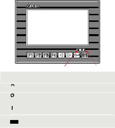
DOP-B07S211 / DOP-B07E215 (Front View)
 D
D
A 
B C
User-defined Function Keys / System Keys
AUser-defined Function Keys: F1, F2, F3, F4 System Keys: Y, Z, , SYS
B


 : Power LED Indicator
Lights in green when HMI works normally.
|
: Operation LED Indicator (Blue) |
|
The operation LED indicator blinks in blue when either the communication is carried |
C |
out or the data is accessing (please refer to the ‘Note’ below for explanation). |
: Alarm LED Indicator (Red)
The alarm LED indicator blinks in red when one of the alarms is on.
D Touch Screen / Display


 NOTE
NOTE
The definition of the operation LED indicator (Blue) can be determined by the users freely.
English-9
DOP-B07S200 / DOP-B07S201 / DOP-B07S211 / DOP-B07E205 / DOP-B07E215 (Rear View)
I
H
 G
G
 F
F
E
|
|
|
A |
B |
|
|
|
C |
D |
||
|
|
|
|
|
|
|
|
|
|
|
|
|
A |
|
Power Input Terminal |
|
|
F |
|
|
Ethernet Interface (LAN) |
|
|
|
|
|
COM3 (RS-232 / RS-422 / RS-485) |
|
|
|
|
|
|
|
|
|
B |
|
(It is provided with two LED indicators |
|
G |
|
|
USB Host |
|
|
|
|
|
to indicate that HMI is in Read or Write |
|
|
|
|
|
||||
|
|
|
status during the communication |
|
|
|
|
|
|
|
|
|
|
|
process.) |
|
|
|
|
|
|
|
|
|
|
|
COM2 (RS-232 / RS-422 / RS-485) |
|
|
|
|
|
|
|
|
|
C |
|
(It is provided with two LED indicators |
|
H |
|
|
Sound Output Interface |
|
||
|
|
to indicate that HMI is in Read or Write |
|
|
|
|
|||||
|
|
|
status during the communication |
|
|
|
|
|
|
|
|
|
|
|
process.) |
|
|
|
|
|
|
|
|
|
D |
|
COM1 (RS-232) |
|
|
I |
|
|
Battery / SD Card Cover |
|
|
|
E |
USB Client |
|
- |
|
- |
|
|
|||
English-10
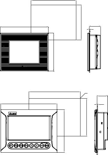
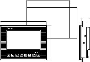
Panel Cut-out
DOP-B05S100
172.4+1(6.79"+0.04")
184(7.24")
144(5.67")
132.4+1(5.21"+0.04")
Note:
T=1.6mm(0.063")~
6mm(0.24")
43.3
T
DOP-B07S200 / DOP-B07S201 / DOP-B07E205 |
|
Units: mm (inches) |
|
|
|
|
|
|
|
196.9 +1.0 (7.75" +0.04") |
|
|
|
|
|
|
4-R3 |
40.5 |
|
|
|
|
|
|
215.0(8.46") |
|
|
T |
NOTE: |
|
|
|
|
|
|
|
|
|
T=1.6 mm(0.063")~ |
|
(5.63" +0.04") |
|
|
6 mm(0.24") |
|
|
|
|
|
161.0(6.34") |
142.9 +1.0 |
|
|
|
Units: mm (inches)
English-11
DOP-B07S211 / DOP-B07E215
196.9+1(7.75" +0.04")
214(8.43")
160(6.3")
142.90+1(5.63"+0.04")
Note:
T=1.6mm(0.063")~
6mm(0.24")
39.4
T
Units: mm (inches)
English-12
 Loading...