

Page 1

DVPEN01-SL
Ethernet Communication Module
Operation Manual
DVP-0204320-02
Page 2

Page 3

Ethernet Communication Module DVPEN01-SL
Warning
3
Please read this instruction carefully before use and follow this instruction to operate the device in order to prevent damages
on the device or injuries to staff.
3
Switch off the power before wiring.
3
RTU-DNET is an OPEN TYPE device and therefore should be installed in an enclosure free of airborne dust, humidity, electric
shock and vibration. The enclosure should prevent non-maintenance staff from operating the device (e.g. key or specific tools
are required for operating the enclosure) in case danger and damage on the device may occur.
3
RTU-DNET is to be used for controlling the operating machine and equipment. In order not to damage it, only qualified
professional staff familiar with the structure and operation of RTU-DNET can install, operate, wire and maintain it.
3
DO NOT connect input AC power supply to any of the I/O terminals; otherwise serious damage may occur. Check all the
wirings again before switching on the power and DO NOT touch any terminal when the power is switched on. Make sure the
ground terminal
is correctly grounded in order to prevent electromagnetic interference.
1 INTRODUCTION...................................................................................................................................3
2 PRODUCT PROFILE & OUTLINE .......................................................................................................4
3 INSTALLATION & WIRING ..................................................................................................................5
4 CONTROL REGISTER (CR) ................................................................................................................6
Table of Contents
1.1 Functions.....................................................................................................................................3
1.2 Specifications ..............................................................................................................................3
2.1 Dimension ...................................................................................................................................4
2.2 Product Profiles...........................................................................................................................4
2.3 LED Indicators.............................................................................................................................5
2.4 RJ-45 PIN Definition....................................................................................................................5
3.1 Installation ...................................................................................................................................5
4.1 Control Registers in DVPEN01-SL.............................................................................................. 6
4.2 Explanations on CR ....................................................................................................................8
4.3 Numbering of Left-Side Modules............................................................................................... 13
5 SETTING UP SOFTWARE.................................................................................................................14
5.1 Setting up Communication & Searching for Modules................................................................14
5.2 Basic Settings ...........................................................................................................................20
5.3 Network Settings .......................................................................................................................21
5.4 Setting up E-Mails .....................................................................................................................24
5.5 Data Exchange..........................................................................................................................25
5.6 RTU...........................................................................................................................................26
5.7 IP Filter......................................................................................................................................27
5.8 Static ARP Table........................................................................................................................27
5.9 Setting up Password .................................................................................................................28
DVP-PLC Operation Manual
1
Page 4

Ethernet Communication Module DVPEN01-SL
5.10 Returning to Default Setting ..................................................................................................... 29
6 APPLICATION EXAMPLES............................................................................................................... 30
6.1 Setting up IP and Communicating through WPLSoft................................................................ 30
6.2 Connecting the PC with DVPEN01-SL through LAN................................................................ 33
6.3 Setting up Password and Clearing Password .......................................................................... 37
6.4 When the Password is Lost (Returning to Default Setting by RS-232)..................................... 39
6.5 IP Filter Protection .................................................................................................................... 40
6.6 Setting up Static ARP Table...................................................................................................... 42
6.7 Application of E-Mail................................................................................................................. 44
6.8 Application of Data Exchange (1) ............................................................................................. 45
6.9 Application of Data Exchange (2) ............................................................................................. 48
6.10 Application of Data Exchange (3) ............................................................................................. 49
6.11 Application of Data Exchange (4) ............................................................................................. 50
6.12 Application of Data Exchange (5) ............................................................................................. 52
6.13 Application of Modbus TCP Master .......................................................................................... 53
6.14 RTU Mapping............................................................................................................................ 54
2
DVP-PLC Operation Manual
Page 5

Ethernet Communication Module DVPEN01-SL
1 Introduction
Thank you for choosing DVPEN01-SL module. To correctly install and operate DVPEN01-SL, please read
the manual carefully before using the module.
DVPEN01-SL is an Ethernet communication module for remote setting and communication through
WPLSoft. DVPEN01-SL is able to send E-mails, automatically correct the RTC in DVP28SV11R/T and
exchange data. It supports Modbus TCP communication protocol and can conduct remote monitoring by using
SCADA (Supervisor Control and Data Acquisition) software or HMI (Human Machine Interfaces). DVPEN01-SL
can be the master of Modbus TCP, sending out Modbus TCP instructions and controlling the peripheral
equipment. In addition, under MDI/MDI-X auto-detection, it does not need to use a crossing cable. See the
contents below for more detailed instructions on DVPEN01-SL module.
1.1 Functions
z Auto-detects 10/100Mbps transmission speed
z MDI/MDI-X auto-detection
z Supports Modbus TCP protocol (at the same time supports Master and Slave mode)
z Able to send out E-mails
z Auto-corrects the RTC in PLC through the Internet time correction function
z Supports point-to-point data exchange (Max. data exchange length: 200 bytes)
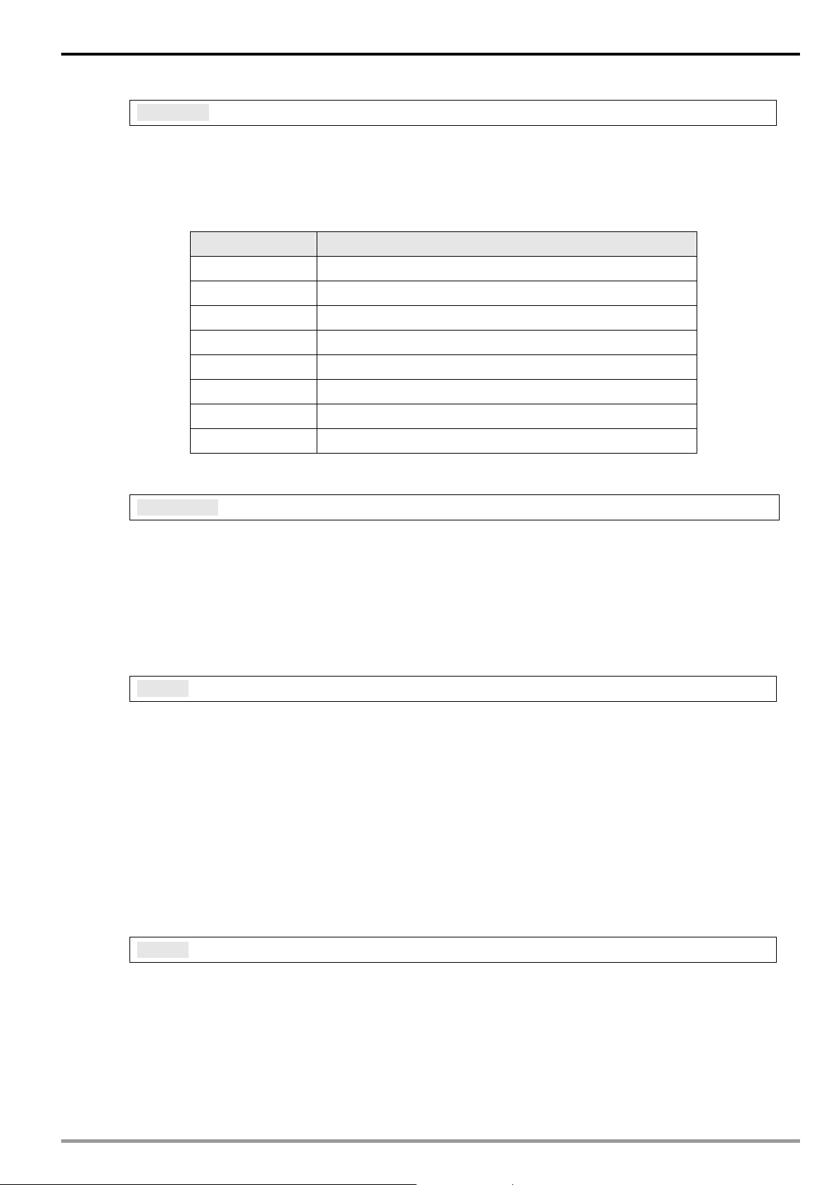
1.2 Specifications
Internet interface
Item Specification
Interface RJ-45 with Auto MDI/MDIX
Number of ports 1 Port
Transmission method IEEE802.3, IEEE802.3u
Transmission cable Category 5e
Transmission speed 10/100 Mbps Auto-Detect
Network protocol ICMP, IP, TCP, UDP, DHCP, SMTP, NTP, Modbus TCP
Serial communication interface
Item Specification
Interface RS-232
Number of ports 1 Port
Transmission cable DVPACAB230, DVPACAB215, DVPACAB2A30, DVPACAB2B10
Environment
Item Specification
Noise immunity
Environment
DVP-PLC Operation Manual
ESD (IEC 61131-2, IEC 61000-4-2): 8KV Air Discharge
EFT (IEC 61131-2, IEC 61000-4-4): Power Line: 2KV
Analog & Communication I/O: 1KV
Damped-Oscillatory Wave: Power Line: 1KV
RS (IEC 61131-2, IEC 61000-4-3): 26MHz ~ 1GHz, 10V/m
Operation: 0°C ~ 55°C (temperature), 50 ~ 95% (humidity), Pollution degree 2;
3
Page 6
Ethernet Communication Module DVPEN01-SL
Item Specification
Storage: -25°C ~ 70°C (temperature), 5 ~ 95% (humidity)
Vibration/ Shock Resistance Standard: IEC61131-2, IEC 68-2-6 (TEST Fc)/IEC61131-2 & IEC 68-2-27 (TEST Ea)
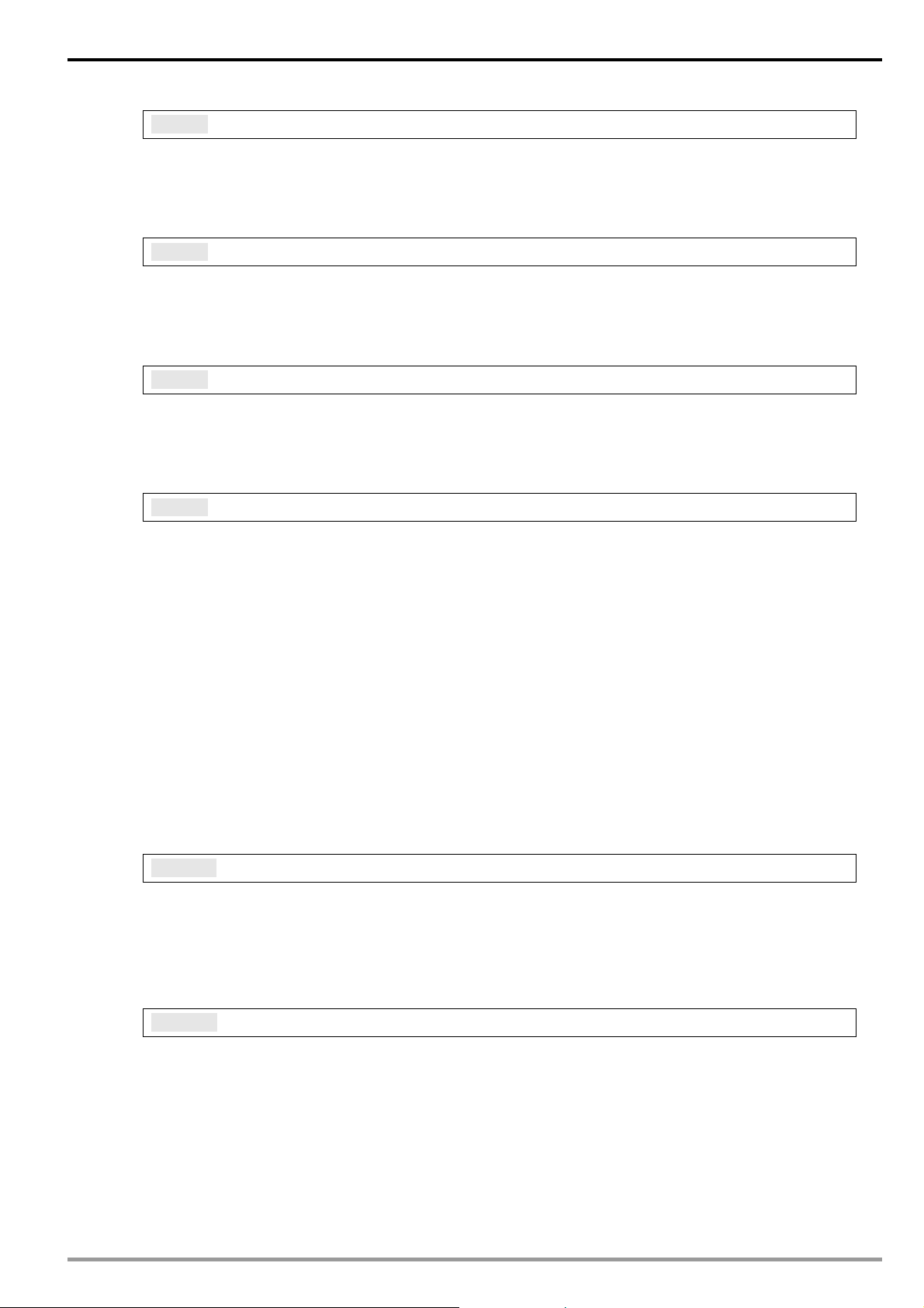
Electrical specifications
Item Specification
Power supply voltage 24VDC (-15% ~ 20%) (Power is supplied by the internal bus of MPU.)
Power consumption 1.5W
Insulation voltage 500V
Weight (g) 92 (g)
2 Product Profile & Outline
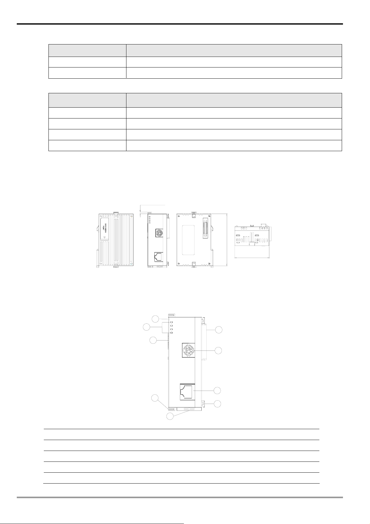
2.1 Dimension
2.2 Product Profiles
3 [0.118]
DVPEN01
POWER
RS-232
100M
LINK
RS-232
LAN
Unit: mm [inches]
1
4
3
DVPEN01
POWER
RS-232
100M
LINK
RS-232
90 [3.543]
60 [2.362]
2
8
4
9
7
1. Model name 6. Fixing tenon for I/O module
2. Extension port to connect device 7. Fixing clip for I/O module
3. Extension port to connect I/O module 8. RS-232 connection port
4. POWER, LINK, RS-232, 100M indicators 9. Ethernet RJ-485 connection port
5. DIN rail clip
LAN
5
6
DVP-PLC Operation Manual
Page 7
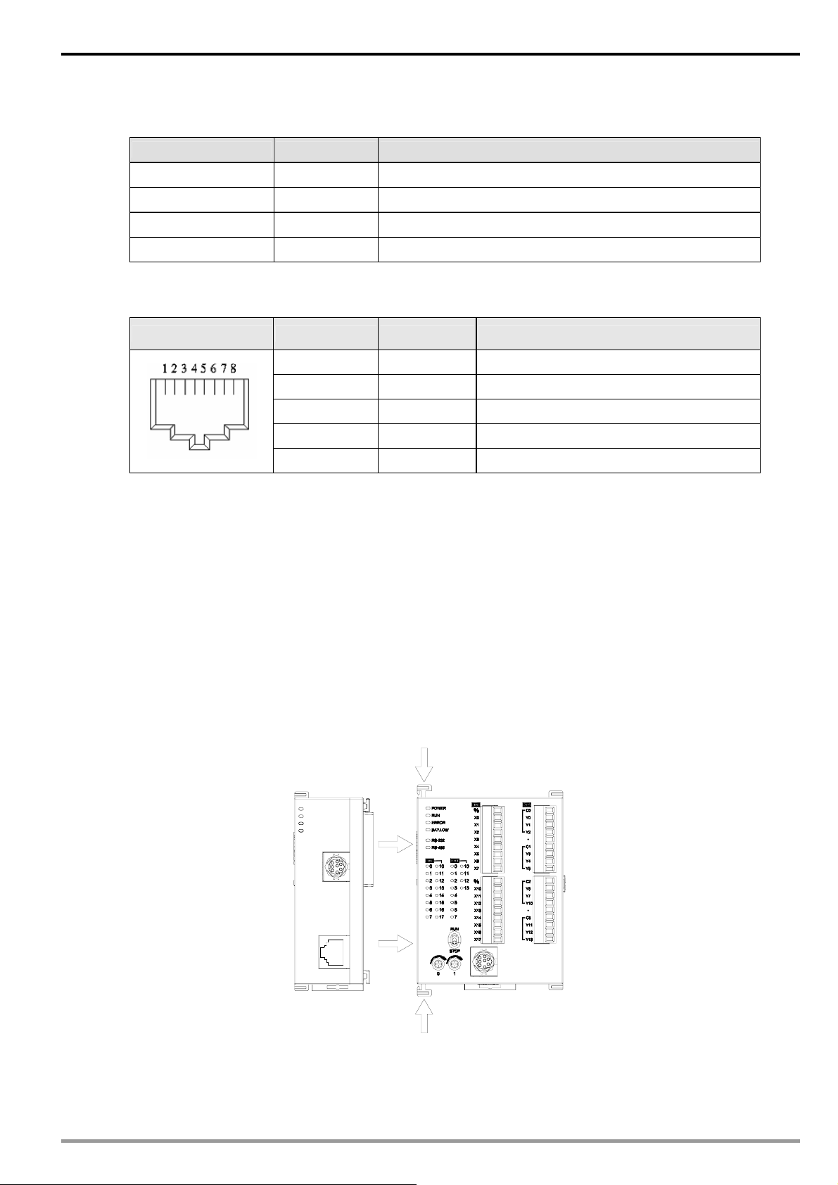
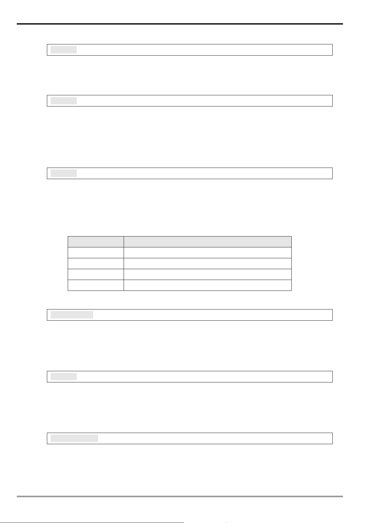
2.3 LED Indicators
Indicator Color Indication
POWER Green Power indication
RS-232 Red Communication status of the series port
100M Orange Network connection status
LINK Green Network communication speed
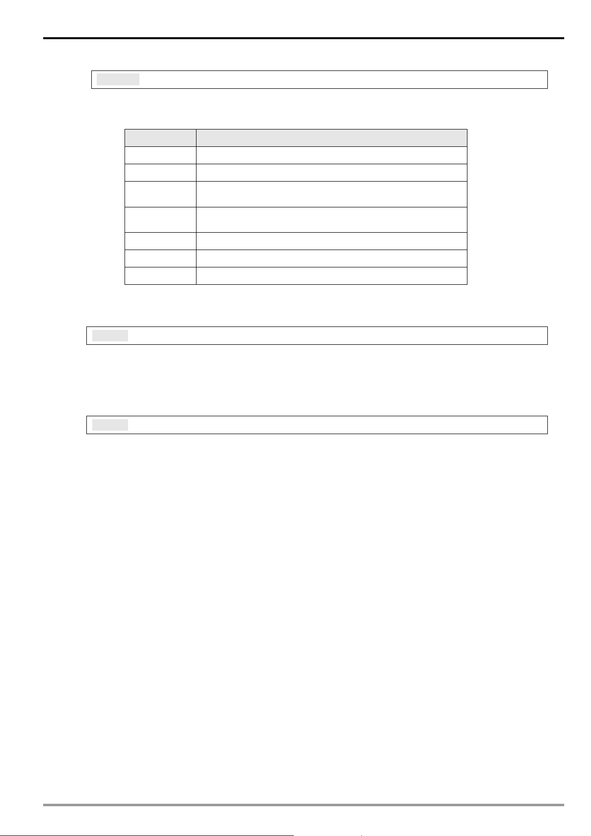
2.4 RJ-45 PIN Definition
RJ-45 sketch Terminal No. Definition Explanation
Ethernet Communication Module DVPEN01-SL
1 Tx+ Positive pole for data transmission
2 Tx- Negative pole for data transmission
3 Rx+ Positive pole for data receiving
6 Rx- Negative pole for data receiving
4, 5, 7, 8 - N/C
3 Installation & Wiring
This section gives instructions on how to connect DVPEN01-SL with PLC MPU and how to connect
DVPEN01-SL to the network.
3.1 Installation
Connect PLC MPU to DVPEN01-SL
z Adjust the I/O module clip on the left side of the MPU.
z Meet the I/O module port of the MPU with DVPEN01-SL as shown in the figure below.
z Fasten the I/O module clip on the left side of the MPU.
DVPEN01
POWER
RS-232
100M
LINK
DVP28SV
RS-232
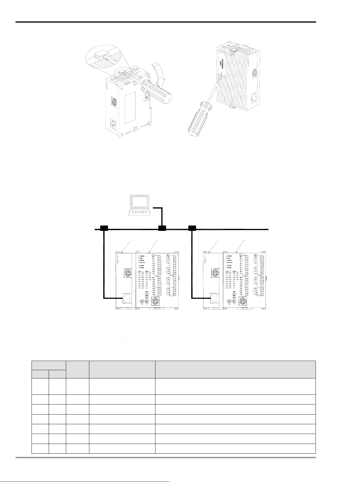
Connect DVPEN01-SL to other I/O modules
z To connect DVPEN01-SL with the other I/O module, lift the extension clip of the I/O module by a
screwdriver and open the side cover.
DVP-PLC Operation Manual
LAN
5
Page 8
Ethernet Communication Module DVPEN01-SL
r
Connect DVPEN01-SL to the Network:
Connect DVPEN01-SL to the Ethernet Hub by twisted pair cable CAT-5e. DVPEN01-SL has Auto MDI/MDIX
function; therefore, DVPEN01-SL does not need to use a crossing cable between the PC and DVPEN01-SL.
Network connections between the PC and DVPEN01-SL:
DVPEN01
DVPEN01
POWER
RS-232
100M
LINK
DVP28SV
RS-232
LAN
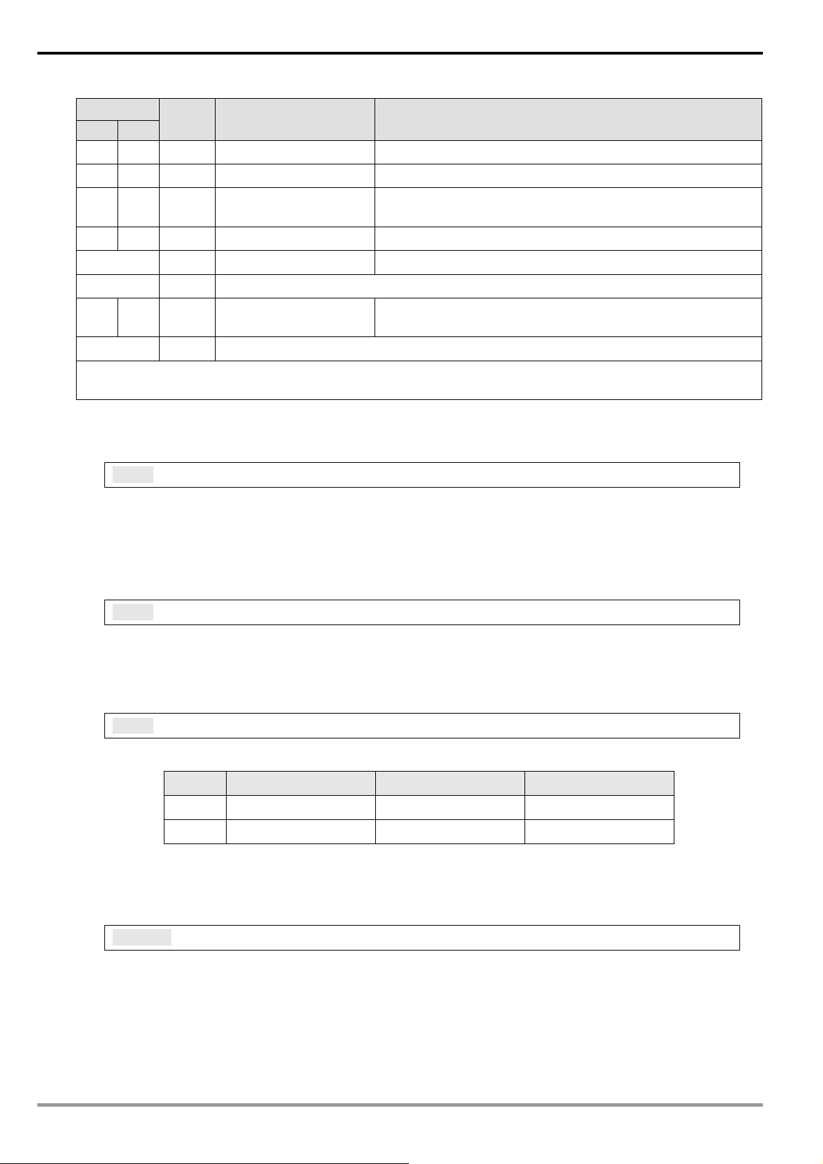
4 Control Register (CR)
4.1 Control Registers in DVPEN01-SL
PC Maste
DVP28SV
DVPEN01
POWER
RS-232
100M
LINK
DVPEN01
RS-232
LAN
Ethernet
DVP28SV
DVP28SV
CR#
Attribute Content Explanation
HW LW
#0 R Model name
Set up by the system; read only. Model code of DVPEN01-SL
= H’4050
#1 R Firmware version Displaying the current firmware version in hex.
#2 R Communication mode b0: Modbus TCP mode; b1: data exchange mode
#3 W E-Mail Event 1 trigger Set up whether to send E-Mail 1
#4 W E-Mail Event 2 trigger Set up whether to send E-Mail 2
#5 W E-Mail Event 3 trigger Set up whether to send E-Mail 3
#6 W E-Mail Event 4 trigger Set up whether to send E-Mail 4
6
DVP-PLC Operation Manual
Page 9

Ethernet Communication Module DVPEN01-SL
CR#
HW LW
#7 R Status of E-Mail 1, 2
#8 R Status of E-Mail 3, 4
#9 R/W
#10 R/W
#11 R/W
#12 R/W
#13 R/W Data exchange trigger Set up whether to send out data in data exchange mode
#14 R Status of data exchange Displaying current status of data exchange.
#15 RW
#16 RW
Attribute Content Explanation
b0 ~ b7: Current status of E-Mail 2
b8 ~ b15: Current status of E-Mail 1
b0 ~ b7: Current status of E-Mail 4
b8 ~ b15: Current status of E-Mail 3
E-Mail 1 additional
message
E-Mail 2 additional
message
E-Mail 3 additional
message
E-Mail 4 additional
message
Enabling flag for RTU
mapping
Connection status of
RTU mapping slave
Filled in by the user, and it will be send by E-mail.
Filled in by the user, and it will be send by E-mail.
Filled in by the user, and it will be send by E-mail.
Filled in by the user, and it will be send by E-mail.
1: Enable; 0: Disable. Default = 0
b0: Status of RTU slave 1
b1: Status of RTU slave 2
b2: Status of RTU slave 3
b3: Status of RTU slave 4
#24 ~ #17 - Reserved
#26 #25 R/W Destination IP Destination IP address for data exchange
#27 - Reserved
#28 R/W Destination Slave ID Destination Slave ID for data exchange
#48 ~ #29 R/W Data transmission buffer Buffer for transmitted data in data exchange
#68 ~ #49 R Data receiving buffer Buffer for received data in data exchange
#80 ~ #69 - Reserved
#81 R/W
#82 R/W
#83 R/W
#84 R/W
#85 R/W
#86 R/W
#110 ~ #87 - Reserved
Read address for data
exchange
Read length for data
exchange
Received address for
data exchange
Written-in address for
data exchange
Written-in length for data
exchange
Transmission address
for data exchange
Slave transmission buffer address for data exchange
Number of registers for read data
Buffer address for the receiving Master in data exchange
Buffer address for the receiving Slave in data exchange
Number of registers for data transmission
Master transmission buffer address for data exchange
#111 R/W 8-bit processing mode Setting up Modbus TCP Master control as 8-bit mode
#112 R/W
#113 - Reserved
#114 R/W Modbus TCP time-out Setting up Modbus TCP time-out (in ms)
DVP-PLC Operation Manual
Modbus TCP Keep-Alive
Time-out
Modbus TCP Keep-Alive Time-out (s)
7
Page 10
Ethernet Communication Module DVPEN01-SL
CR#
HW LW
#115 R/W Modbus TCP trigger Setting up whether to send out data in Modbus TCP mode
#116 R/W Modbus TCP status Displaying current status of Modbus TCP mode
#118 #117 R/W
#119 R/W Modbus TCP data length Setting up the data length for Modbus TCP transaction
#219 ~ #120 R/W Modbus TCP data buffer Data buffer of Modbus TCP for storing sending/receiving data
#248 ~ #220 - Reserved
#251 R Error code
#255 ~ #252 - Reserved
Symbols “R” refers to “able to read data by FROM instrcution”; “W” refers to “able to write data by TO
instrcution”.
Attribute Content Explanation
Modbus TCP
destination IP
Setting up destination IP address for Modbus TCP transaction
Displaying the errors. See table of error codes in the following
section for more information.
4.2 Explanations on CR
CR#0: Model Name
Explanations:
CR#1: Firmware Version
Explanations:
CR#2: Communication Mode
Explanations:
E-mail Functions
1. Model code of DVPEN01-SL = H’4050.
2. You can read the model code in the program to see if the I/O module exists.
The firmware version of DVPEN01-SL is displayed in hex, e.g. H’0100 indicates version V1.00.
Bit No. Mode “0” “1”
b0 Modbus TCP Disable Enable
b1 Data exchange Disable Enable
8
CR#3 ~ 6: E-Mail Event 1 ~ 4 Trigger
Explanations:
When the CR is set as “1”, E-mail sending will be enabled. After the sending is completed, the
CR will automatically be reset as “0”. Note: Please trigger by differential instructions.
DVP-PLC Operation Manual
Page 11
Ethernet Communication Module DVPEN01-SL
CR#7 ~ 8: Status of E-Mail 1 ~ 4
Explanations:
1. CR#7_b0 ~ b7: current status of E-Mail 2; CR#7_b8 ~ b15: current status of E-Mail 1.
2. CR#8_b0 ~ b7: current status of E-Mail 4; CR#8_b8 ~ b15: current status of E-Mail 3.
3. Table of E-Mail status
CR value E-Mail status
0 Not been sent
1 Being processed
2 E-Mail sending is successful
10 Fail to connect to SMTP-Server
11 Incorrect recipient E-Mail address
12 SMTP-Server communication error
13 Exceeding the max. number of TCP connection
3 ~ 9, 14 ~ 255 Reserved
CR#9 ~ 12: E-Mail 1 ~ 4 Additional Message
Explanations:
The user fills in the code, and the code will be stored in the title of the E-Mail and sent out with the
E-Mail.
Data Exchange
CR#13: Data Exchange Trigger
Explanations:
When the CR is set as “0”, the data in data exchange area will not be transmitted. When the CR is
set as “1”, the data in data exchange area will be transmitted.
f When the Execute Mode in the software is set to “Program Control” (See 5.5), set CR#13 to 2,
and the data exchange will continue to execute. Set CR#13 to 0 to stop the data exchange.
f When the Execute Mode in the software is set to “Always Enable”, the data exchange will
continue to execute whatever the setting in CR#13 is.
(Firmware V2.0 and later versions support continuous execution of data exchange.)
CR#14: Data Exchange Status
Explanations:
When the CR is set as “0”, the data have not yet been received. When the CR is set as “1”, the
data exchange is in progress. When the CR is set as “2”, the data exchange is successful. When
the CR is set as “3”, the data exchange fails.
DVP-PLC Operation Manual
9
Page 12

Ethernet Communication Module DVPEN01-SL
CR value Status
0 Data have not yet been received.
1 Data exchange is in progress.
2 Data exchange is successful.
3 Data exchange fails.
CR#25, 26: Destination IP
Explanations:
To set up the Slave IP address for data exchange manually, write “0” into CR#28 first before
setting up the destination IP. For example, if the user wants to set the destination IP address to
192.168.0.2, write H’0002 to CR#25 and H’C0A8 to CR#26. (K192 = H’C0, K168 = H’A8, K0 =
H’00, K2 = H’02).
CR#28: Destination Slave ID
Explanations:
When you set up the Salve ID (i.e. K1 ~ K255) for data exchange, DVPEN01-SL will
automatically search for the corresponding IP address from the Slave IP list. For example, if the
ID is set as “0”, the value in CR#25 and #26 will be regarded as the destination IP.
CR#29 ~ 48: Data Transmission Buffer
Explanations:
Storing the data to be transmitted to the remote MPU.
CR#49 ~ 68: Data Receiving Buffer
Explanations:
Storing the data received from the remote MPU.
CR#81: Read Address for Data Exchange
10
Explanations:
Setting up manually the Modbus address of the register for Slave data exchange. Only register
address is allowed (e.g. D0 = H’1000).
CR#82: Read Length for Data Exchange
Explanations:
The number of receiving registers (K1 ~ K100) in data exchange.
DVP-PLC Operation Manual
Page 13
Ethernet Communication Module DVPEN01-SL
CR#83: Read Length for Data Exchange
Explanations:
Setting up the Modbus address of the register for Master data exchange.
CR#84: Written-in Address for Data Exchange
Explanations:
Setting up manually the Modbus address of the register for Slave data exchange.
CR#85: Written-in Address for Data Exchange
Explanations:
The number of transmission registers (K1 ~ K100) in data exchange.
CR#86: Transmission Address for Data Exchange
Explanations:
1. Setting up the Modbus address of the register for Master data exchange.
2. Example: Write H’1000 (D0) into CR#81, K1 into CR#82, and H’1064 (D100) into CR#83. If
the data exchange is successful, the value in D0 of the Slave will be written into D100 of the
MPU. Or write H’1002 (D2) into CR#84, K4 into CR#85, and H’1008 (D8) into CR#86. If the
data exchange is successful, the value in D8 ~ D11 of the Master will be written into D2 ~ D5
of the Slave. Both sending and receiving can be executed at the same time. When the values
in CR#82 and #85 are both “0”, DVPEN01-SL will use the default registers (CR#29 ~ CR#68)
and number of registers (K20).
Sending Modbus TCP Instruction
CR#111: 8-bit Processing Mode
Explanations:
Setting up the Modbus TCP transmission mode. When the CR value is set as “0” Æ 16-bit mode;
when the CR value is set as “1” Æ 8-bit mode.
CR#112: Modbus Client Keep-Alive Time-out
Explanations:
CR#112 is the TCP Keep-Alive time-out for Modbus TCP connection (s). Default: 30s. If the
connection idle time becomes longer than the keep-alive time-out, DVPEN01-SL will cut off the
idle connection.
DVP-PLC Operation Manual
11
Page 14
Ethernet Communication Module DVPEN01-SL
CR#114: Modbus TCP Time-Out
Explanations:
Setting up the communication time-out (in ms) for Modbus TCP mode.
CR#115: Modbus TCP Trigger
Explanations:
When the CR value is set as “1”, Modbus TCP will be triggered. After the data transmission is
completed in Modbus TCP mode, the CR value will automatically be reset to “0”. Please trigger
by differential instructions.
CR#116: Modbus TCP Status
Explanations:
Displaying the current communication status of Modbus TCP mode. When the CR value is set
as”0” Æ the data have not yet been received; when the CR value is set as “1” Æ the data
exchange is in progress; when the CR value is set as “2” Æ the data exchange is successful;
when the CR value is set as “3” Æ the data exchange fails.
CR value Data exchange status
0 The data have not been received.
1 The data exchange is in progress.
2 The data exchange is successful.
3 The data exchange fails.
CR#117, 118: Modbus TCP Destination IP
Explanations:
Setting up the destination IP address in Modbus TCP mode. See explanations on CR#70 and
#71 for how to set.
CR#119: Modbus TCP Data Length
12
Explanations:
Setting up the length of communication data in Modbus TCP mode. Length for 8-bit mode: K1
~K100; length for 16-bit mode: K1 ~ K200.
CR#120 ~ 219: Modbus TCP Data Buffer
Explanations:
Buffer for transmitted/received data in Modbus TCP mode.
DVP-PLC Operation Manual
Page 15
CR#251: Error Code
Explanations:
Table of error code:
Bit No. Error
RTU Mapping
Ethernet Communication Module DVPEN01-SL
b0 The network is not yet connected.
b1 Incorrect IP setting
b2
b3
b4 NTP-Server connection fails.
b7 SMTP-Server connection fails.
b8 DHCP has not obtained the correct network parameter.
CR#13 is set as “transmitting data”, but the data exchange
is forbidden.
CR#13 is set as “transmitting data”, but the data exchange
mode has not yet been enabled.
CR#15: Enabling Flag for RTU Mapping
Explanations:
1: Enable; 0: Disable. Default = 0
Firmware V2.0 and later versions support RTU mapping.
CR#16: Connection Status of RTU Mapping Slave
Explanations:
b3 ~ b0 display the connection status of RTU slave. The connection may encounter some
problems when any of the bits becomes 0. Firmware V2.0 and later versions support RTU
mapping.
b0: Status of RTU slave 1
b1: Status of RTU slave 2
b2: Status of RTU slave 3
b3: Status of RTU slave 4
4.3 Numbering of Left-Side Modules
After DVPEN01-SL is installed properly, you need to compile the PLC program to control the special I/O
module. PLC offers FROM instruction (for reading) and TO instruction (for writing) to control the control registers
(CR) in the special I/O module.
Numbering of the modules: Every special I/O module connected to PLC MPU has a No. to allow you to know
which module is which when compiling the PLC program. The first special I/O module attached at the left hand
side of the PLC MPU is numbered as K100, the second as K101, the third K102, and so on.
DVP-PLC Operation Manual
13
Page 16
Ethernet Communication Module DVPEN01-SL
5 Setting up Software
This section gives instructions on how to set up DVPEN01-SL by DCISoft and explanations on each setup
page. Before you start a setup page, you have to select “Ethernet” in the communication setting. Next, you can
search by IP address or use Auto-Search. You also can open the setup page for DVPEN01-SL by RS-232.
DVPEN01-SL is set up by UDP port 20006; therefore, you have to be aware of the relevant settings of the
firewall.
5.1 Setting up Communication & Searching for Modules
Communication settings
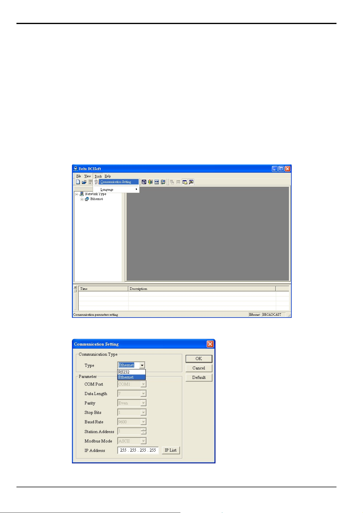
1. Open DCISoft in your PC and click on “Communication Setting”.
14
2. Select “Ethernet” as the transmission type.
DVP-PLC Operation Manual
Page 17
Ethernet Communication Module DVPEN01-SL
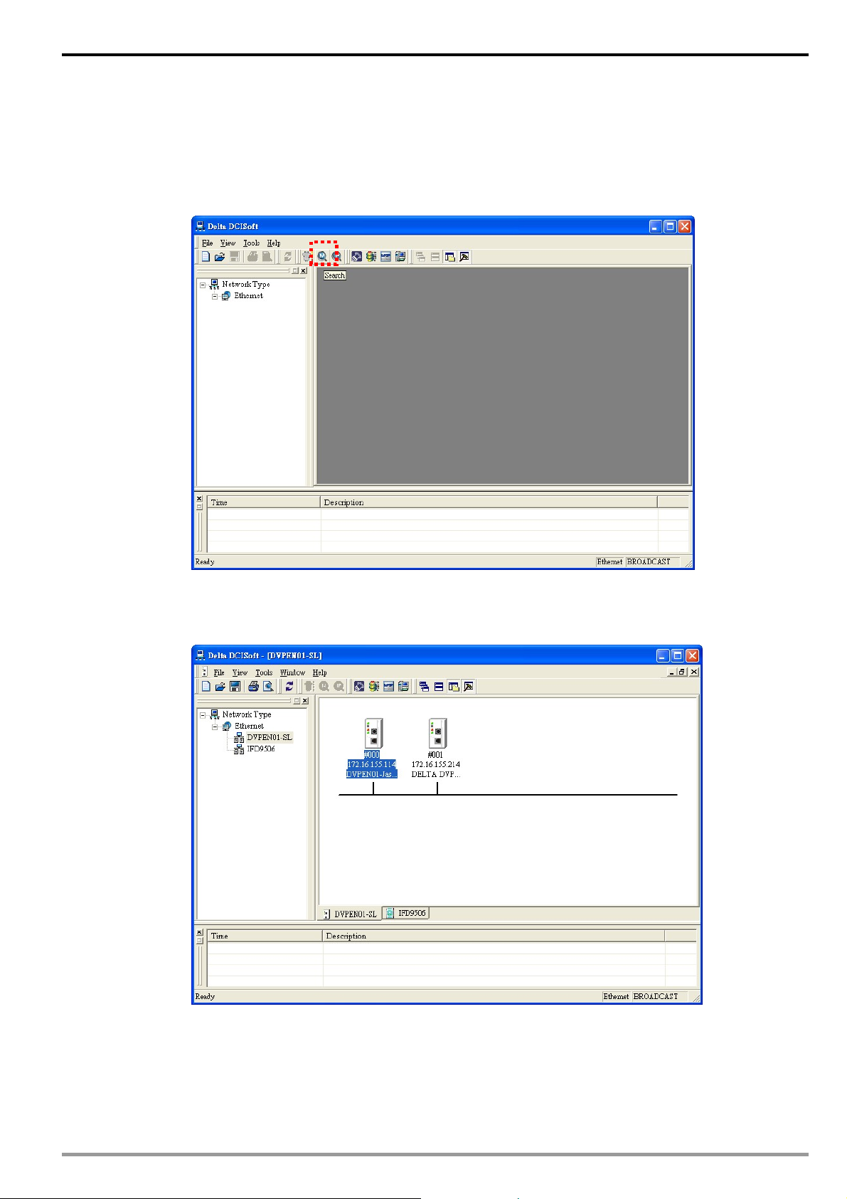
Broadcast search
1. Click broadcast icon in DCISoft to search for all Delta Ethernet products on the network. The
window on the left hand side shows the models found, and the window on the right hand side
displays the device list of all models.
2. Click a model on the left hand side, and you will see the device list of the model selected on the
right hand side. Click the device to be set up to enter the setup page.
DVP-PLC Operation Manual
15
Page 18
Ethernet Communication Module DVPEN01-SL
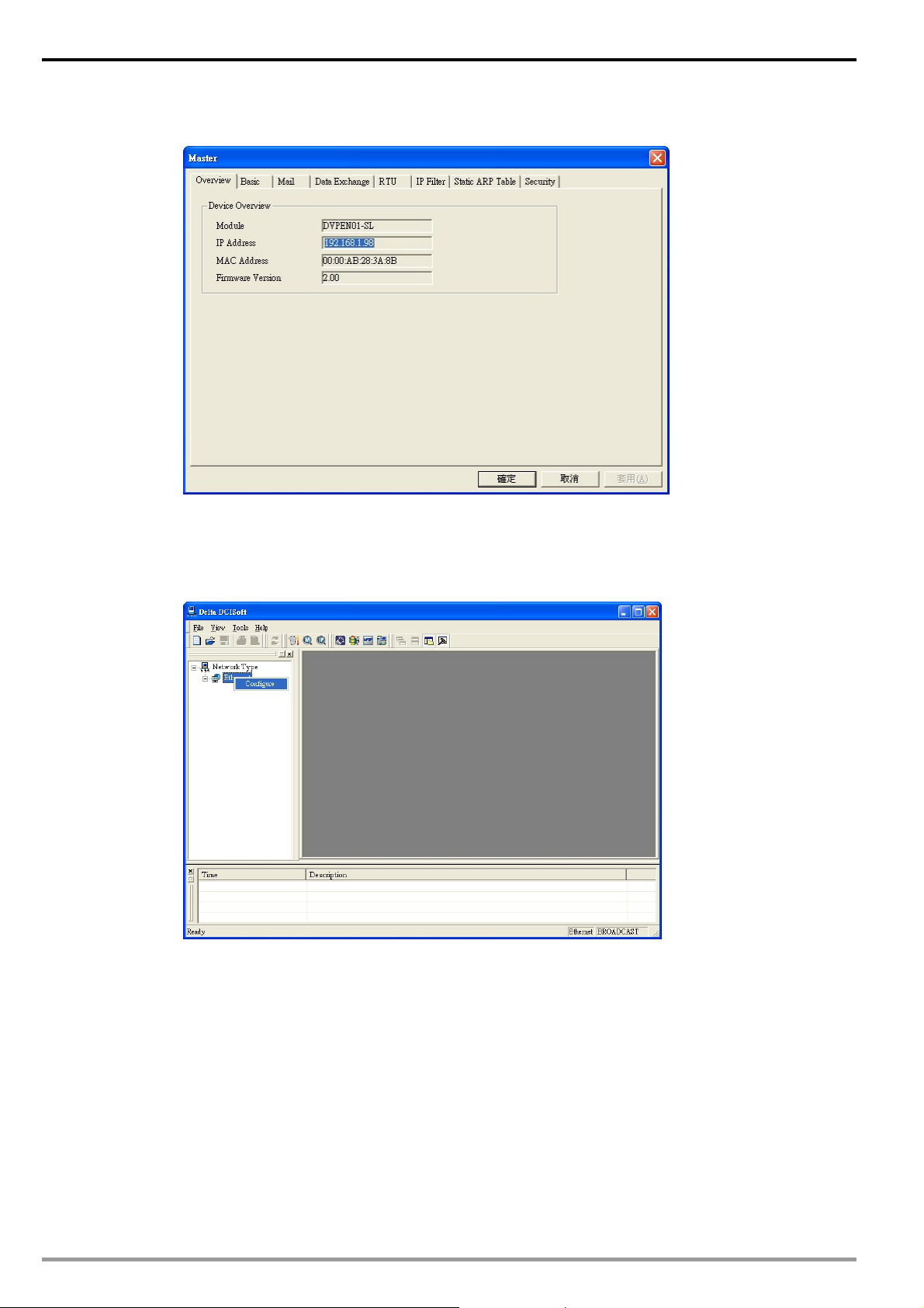
3. You will see the basic setup page as follow.
Designating model to search
1. Right click “Ethernet” on the left hand side window and select “Configure” to designate a model to
search for.
16
DVP-PLC Operation Manual
Page 19

Ethernet Communication Module DVPEN01-SL
2. After configure a model, select “DVPEN01-SL” and click “OK” to auto-search for DVPEN01-SL
modules on the network.
3. List of the current DVPEN01-SL modules
DVP-PLC Operation Manual
17
Page 20

Ethernet Communication Module DVPEN01-SL
Searching by IP address
1. Set the communication type to “Ethernet” and enter the IP address. Click “OK”.
2. Click “IP Search” icon to start searching for the designated IP.
3. The DVPEN01-SL module found will be displayed in the right hand side window. Double click it
18
to enter the setup page.
DVP-PLC Operation Manual
Page 21

Ethernet Communication Module DVPEN01-SL
Opening DVPEN01-SL setup page by RS-232
1. Select “RS232" as the transmission type in communication setting. You will have to designate a
communication port. When DVPEN01-SL is searched by RS-232, you do not need to set up the
parameters (i.e. data length, parity, stop bits and baud rate).
2. After setting up the communication port, press “broadcast search” icon. If the searching is
successful, the setup page for DVPEN01-SL will open automatically.
DVP-PLC Operation Manual
19
Page 22

Ethernet Communication Module DVPEN01-SL
5.2 Basic Settings
The basic settings include parameters as module name, language, enabling Modbus TCP and time
correction.
Setting up DVPEN01-SL basics
1. Module Name:
There can be many DVPEN01-SL modules in the network. Thus, you can set up a module name
for each module to identify the module when you need to use them.
2. Module Language:
You can select a language for each module name, and the windows will be displayed in the
selected language.
3. Enable Modbus TCP:
To enable or disable Modbus TCP. When Modbus TCP is disabled, WPLSoft will not be able to
upload or download.
4. Enable time correction:
DVPEN01-SL adopts NTP (Network Time protocol), which means it can acquire correct time
automatically from the time server in the network and correct the RTC in the MPU every fixed
period of time to ensure correct time in the MPU. The default setting of this function is “disable”.
5. Start Daylight Saving Time:
Daylight Saving Time; also known as summer time is a conventional local time adopted by many
countries in the world on a seasonal basis. Most commonly DST is obtained by adjusting the
official local time forward, by one hour, for the spring, summer, and early autumn periods.
Daylight Saving Time is not implemented in Taiwan; therefore, you do not need to check this
20
item.
6. Time Server:
IP address of the time server. You can acquire correct time from the time server to correct the
time in the MPU.
DVP-PLC Operation Manual
Page 23

Ethernet Communication Module DVPEN01-SL
A
7. Time Zone:
time zone is a region of the Earth that has adopted the same standard time, usually referred to
as the local time. Most adjacent time zones are exactly one hour apart, and by convention
compute their local time as an offset from Greenwich Mean Time (see also UTC). Standard time
zones can be defined by geometrically subdividing the Earth's spheroid into 24 lunes
(wedge-shaped sections), bordered by meridians each 15° of longitude apart. The local time in
neighboring zones is then exactly one hour different. However, political and geographical
practicalities can result in irregularly shaped zones that follow political boundaries or that
change their time seasonally (as with daylight saving time), as well as being subject to
occasional redefinition as political conditions change. You should choice the Time zone that you
are.
5.3 Network Settings
The first step for all the network equipment to connect to the network is to have its own IP address (Internet
Protocol). The IP address is like a number for every network equipment to be identified in the network.
Setting up static IP of the PC
1. Enter Control Panel → Network Connection → click on “Local Area Connection”
2. You will see the “Local Area Connection Status” window. Click on “Properties”.
DVP-PLC Operation Manual
21
Page 24

Ethernet Communication Module DVPEN01-SL
3. Click on “Internet Protocol (TCP/IP).
4. Enter 192.168.0.1 into IP address. Click on “OK” to complete the IP address setting of the PC.
22
DVP-PLC Operation Manual
Page 25

Ethernet Communication Module DVPEN01-SL
Setting up DVPEN01-SL Net work
1. IP configuration:
There are two types of IP, static IP and DHCP.
Static IP: Preset or manually modified by the user.
DHCP: Automatically updated by the server. There has to be a server in the LAN.
DHCP DHCP server offers the IP address, subnet mask and gateway.
2. IP address:
IP address is the location of the equipment in the network. Every equipment connected to the
network has to have an IP address. Incorrect IP address will result in connection failure on the
equipment or even other equipment. Ask your ISP for questions about IP address setup. The default
IP for DVPEN01-SL is 192.168.1.5.
3. Subnet mask:
Subnet mask is an important parameter for setting up the subnet, used for seeing if the destination
IP and the local equipment are in the same subnet. If not, the equipment will send the packet to the
gateway, and the gateway will send the packet to another subnet. Incorrect setting may cause the
IP Explanation
Static The user enters the IP address, subnet mask and gateway.
destination equipment unable to communicate with DVPEN01-SL. To see if your setting is correct,
conduct bitwise AND operations between your IP and subnet mask and destination IP and subnet
mask. If the two values obtained are the same, the two IPs are in the same subnet. The default
subnet mask of DVPEN01-SL is 255.255.255.0.
4. Gateway:
Gateway is the gate for two different subnets, allowing the two ends in different subnets to
communicate. For example, if the LAN has to be connected to WAN, it will need a gateway to bridge
the communication. The IP of the gateway has to be in the same subnet as DVPEN01-SL. The
default gateway IP address of DVPEN01-SL is 192.168.1.1.
DVP-PLC Operation Manual
23
Page 26

Ethernet Communication Module DVPEN01-SL
5.4 Setting up E-Mails
E-mail is the abbreviation of electronic mail, which transmits mails through the network. DVPEN01-SL has
E-Mail functions for the user to pre-save a segment of text messages, which can be a descriptive message or
error message, into the subject of the E-Mail. When the E-Mail is triggered, DVPEN01-SL will send the
messages to the user by E-Mail.
DVPEN01-SL offers 4 sets of E-Mail information, and you can self-define the register or bit information to be
read. When the trigger occurs, DVPEN01-SL will add the set register or bit present value read to the E-Mail.
Every set of E-Mail information is able to contain maximum 100 continuous register data.
Setting up DVPEN01-SL mail
1. SMTP Server:
The E-Mail will first be sent to SMTP server, and SMTP server will send it to the designated
address. For example, assume there is an E-Mail to be sent to test@delta.com.tw
SMTP server is 172.16.144.121. The E-Mail will be sent to SMTP server first, and the server will
further send it to the recipient test@delta.com.tw
2. Subject of E-Mail:
You can enter text message in the column, and the message will be placed in the subject of the
E-Mail and sent to the recipient. DVPEN01-SL is able to contain 1 ~ 4 E-Mail subjects (max. 63
English characters are allowed).
You can select additional information for the E-Mail. Every set of E-Mail is able to contain 100
continuous addresses of registers.
3. E-Mail of Sender:
Maximum 63 English characters are allowed.
4. E-mail of Recipient:
You can enter 4 E-Mail addresses. One mail can be sent to 4 addresses (max. 63 English
characters are allowed).
, and the
.
24
5. Select recipients:
After you have set up all the parameters for the E-Mail, you will need to select recipients. The
DVP-PLC Operation Manual
Page 27

Ethernet Communication Module DVPEN01-SL
E-Mail will be sent to the designated recipients when the E-Mail is triggered. To trigger E-Mail, set
the value is CR#3 ~ CR#6 as “1”.
6. See “Application Examples Section 6.8” for more details.
Notes:
To correctly send out E-Mails, there has to be a SMTP server in the network. When we send out
an E-Mail, the mail will be sent to SMTP server first, and the server will further send the mail to the
designated address.
5.5 Data Exchange
DVPEN01-SL is able to designate a data exchange area for PLC MPUs to exchange and synchronize their
data.
Setting up DVPEN01-SL data exchange
1. Enable Data Exchange:
Check the box to enable or disable data exchange. Start data exchange after enable it.
2. Execute Mode:
You can set it to ”Always Enable” or ”Program Control”. When set to “Always Enable”,
DVPEN01-SL will execute data exchange continuously until the setting in DCISoft is changed.
When set to “Program Control”, DVPEN01-SL will execute data exchange according to the
program setting (CR#13 = 2: Execute; CR#13 = 0: Stop).
3. Communication Address & Data exchange host IP:
You have to enter the IP address of DVPEN01-SL at the other end. For example, if you would
like DVPEN01-SL to exchange data with 192.168.0.1, set No. 1 as 192.168.0.1. When the data
are being exchanged, if the value in CR#28 is H’0001, the data will be exchanged with
192.168.0.1.
4. Master Address & Slave address & Quantity.
Read (Å): Start address of the master’s receiving register Å Start address of the slave’s
sending register
Write (Æ): Start address of the master’s sending register Æ Start address of the slave’s
DVP-PLC Operation Manual
25
Page 28

Ethernet Communication Module DVPEN01-SL
receiving register
In data exchange, DVPEN01-SL will execute Write (Æ) first before Read (Å).
Quantity: A slave is able to send and receive at the same time maximum 100 consecutive data.
f For data exchange, D register is parted into 2 sections, D0000 ~ D4095 and D4096 ~ D9999.
Please DO NOT use different sections for the consecutive sent and received data (start
address + number of data).
5. See “Application Examples Section 6.11” for more details.
5.6 RTU
Use the “RTU” function to conduct mapping between Delta’s network modules DVPEN01-SL and
RTU-EN01.Set up the mapping information first, and you will be able to use WPLSoft in DVPEN01-SL to save
and retrieve the mapped bit (M) and register (D) in order to operate the remote RTU-EN01.
The settings
1. Enable Remote I/O Mapping:
Check the box to enable the remote I/O mapping. The mapping with remote RTU-EN01 will be
enabled according to the settings.
2. Communication Parameters:
Set up “Communication Timeout” (ms) and “Update Cycle” (ms) here.
3. PLC I/O Mapping:
Set up the start address of the mapped bit and analog register (RCR) of digital input (X) and
digital output (Y) on remoter RTU-EN01. The bit starts from M2000, and read/write register starts
from D2000/D3000. The software will automatically calculate the end address according to the
settings below.
4. Remote Device Mapping:
Check “Enable” and enter the remote RTU-EN01 ID (Slave ID), IP Address, number of digital
input points (RX), number of digital output points (RY), number of mapped read registers (Read)
and write register (Write).
DVPEN01-SL offers 4 slaves for mapping. Max. number of digital and analog points for mapping
26
DVP-PLC Operation Manual
Page 29

Ethernet Communication Module DVPEN01-SL
of every slave:
Digital I/O points (RX+RY): 256
Analog (Read) register: 64
Analog (Write) register: 64
5.7 IP Filter
IP filter is used for restricting the connection of the network in case some uncertain IP will cause errors. Only
the IP set within a certain range can establish a connection. Other IPs will be rejected.
Setting up IP filter
1. Enable IP Filter Function:
Check the box to enable IP filter.
2. IP:
IP addresses that are allowed to establish connections. Maximum 8 IPs are allowed.
3. Netmask:
The subnet of the IP is allowed to establish a connection. To see whether the destination IP is
allowed, conduct bitwise AND operations between the allowed IP and subnet mask and destination
IP and subnet mask. If the two values obtained are the same, the destination IP is allowed by the IP
filter. For example, assume the IP is 192.168.0.1 and subnet mask 255.255.255.255, the only one IP
allowed to establish a connection is 192.168.0.1. If the subnet mask is 255.255.255.0, the IPs
allowed to establish connections will become 192.168.0.0 ~ 192.168.0.255.
5.8 Static ARP Table
ARP (Address Resolution Protocol) is used for obtaining the MAC address corresponding to the IP address
in data transmission. For example, there is a datum to be sent to 172.16.155.250, but you do not know the
corresponding MAC address. You can use ARP to look up the MAC address by IP address, and the
corresponding MAC address will be saved, so you do not need to look it up again when sending the next datum.
DVP-PLC Operation Manual
27
Page 30

Ethernet Communication Module DVPEN01-SL
Therefore, if you do not know the MAC address, you will have to spend some time looking up the MAC address.
If you want to enhance the transmission efficiency, use static ARP table to save time. For example, assume IP:
192.168.0.1 and MAC: 00:14:22:56:0F:7F. As long as there are data sent to 192.168.0.1, you will get the MAC
address from the table.
Setting up static ARP table
1. IP:
Destination IP address in data transmission.
2. MAC:
The MAC addresses corresponding to the IP address.
Note:
Incorrect settings may result in connection failure. Therefore, DO NOT set the MAC address of
the equipment without the network into the table.
5.9 Setting up Password
To prevent the set values in DVPEN01-SL from being modified, you can set up password to lock the settings
in DVPEN01-SL.
Setting up DVPEN01-SL password
28
DVP-PLC Operation Manual
Page 31

1. Modify:
Ethernet Communication Module DVPEN01-SL
Check the box to modify the password.
2. New Password:
Maximum 4 characters are allowed. Leave the column “blank” to disable the password
protection function.
3. Confirm Password:
Enter the new password again.
4. See “Application Examples Section 6.4” for more details.
Note:
After the password is locked, all the pages cannot be set up unless you unlock the password.
However, if you set up DVPEN01-SL by RS-232, you can return the setting to default setting
whether the password is locked or not. For example, if you have locked DVPEN01-SL but forget
the password, you have to return DVPEN01-SL to factory default setting by RS-232, and all the
settings will return to default ones.
5.10 Returning to Default Setting
If you need to clear all the settings after many modifications on the settings and return the settings to default
ones, check the “default setting” box.
DVPEN01-SL returning to default setting
DVP-PLC Operation Manual
29
Page 32

Ethernet Communication Module DVPEN01-SL
Check “Default Setting” box and click on “Yes”.
Note:
If you set up DVPEN01-SL by RS-232, you can return the setting to default setting whether
the password is locked or not. It takes approximately 10 seconds to return to default setting,
so DO NOT
switch off the power within the 10 seconds.
6 Application Examples
6.1 Setting up IP and Communicating through WPLSoft
Application Setting up network parameters of DVPEN01-SL directly on the PC.
Network
requirement
1. The connection
(1) IP of PC executing WPLSoft: 192.168.0.3
(2) Subnet mask: 255.255.255.0; Gateway: 192.168.0.1
(3) IP of DVPEN01-SL: 192.168.0.4
(4) Connect the PC and DVPEN01-SL by RJ-45 cable.
Note: Both PC and DVPEN01-SL have to adopt static IP.
DVPEN01
PC
DVP-P LC
30
2. Open "Communication Setting” in WPLSoft.
DVP-PLC Operation Manual
Page 33

Ethernet Communication Module DVPEN01-SL
3. Select “Ethernet” and press "OK”.
4. Click on “Auto-Search” icon to search for all DVPEN01-SL modules in the network.
5. Designate a DVPEN01-SL and double click it to open the setup page.
DVP-PLC Operation Manual
31
Page 34

Ethernet Communication Module DVPEN01-SL
6. Open “Basic” setup page.
7. Switch to “Network” setup page
32
DVP-PLC Operation Manual
Page 35

Ethernet Communication Module DVPEN01-SL
8. Enter IP address: 192.168.0.4; Netmask: 255.255.255.0; Gateway: 192.168.0.1. Press “OK” to
complete the setup, and WPLSoft will automatically search for DVPEN01-SL.
9. The IP of DVPEN01-SL has been modified into the new setting (DELTA DVPEN01-SL:
192.168.0.4).
10. Click on DELTA DVPEN01-SL, and WPLSoft will be able to communicate with the MPU.
6.2 Connecting the PC with DVPEN01-SL through LAN
Application Setting up network parameters of DVPEN01-SL by WPLSoft through LAN.
Network
requirement
1. The connection
(1) Connect the PC and DVPEN01-SL by using DHCP server through LAN.
(2) IP of DVPEN01-SL: 172.16.157.148
Note: DVPEN01-SL can use RJ-45 cable with/without jump wire.
DVP-PLC Operation Manual
33
Page 36

Ethernet Communication Module DVPEN01-SL
PC
PC
Hub
2. Open “Communication Setting” in WPLSoft.
DHCP Server
DVPEN01
DVP-PLC
3. Select “Ethernet” and press “OK”.
34
DVP-PLC Operation Manual
Page 37

Ethernet Communication Module DVPEN01-SL
4. Click on “Auto-Search” icon to search for all DVPEN01-SL modules in the network. Follow “View Æ
Workspace Æ Communication” or “View Æ Workspace Æ Project” to find the detected
DVPEN01-SL module (default module name: DELTA DVPEN01-SL, IP: 192.168.1.5) in the window.
5. Designate a DVPEN01-SL and double click it to open the setup page.
DVP-PLC Operation Manual
35
Page 38

Ethernet Communication Module DVPEN01-SL
6. Open the setup page. You can modify the module name for easier identification.
7. Next, set up the new IP of DVPEN01-SL. First switch to “Network” setup page. If there is a DHCP
server in the LAN, select DHCP in “IP Configuration”. If there is no DHCP server in the LAN, you can
set a static IP. Please be noted that the settings of subnet mask and gateway have to be the same
as the settings in the same LAN. Press “OK” to complete the setting, and WPLSoft will automatically
search for DVPEN01-SL.
36
8. The module name and IP of DVPEN01-SL have been modified into new settings (TEST:
172.16.157.148).
9. Click on DVPEN01-SL, and WPLSoft will be able to communicate with the MPU (e.g.
uploading/downloading program or monitoring devices).
DVP-PLC Operation Manual
Page 39

Ethernet Communication Module DVPEN01-SL
6.3 Setting up Password and Clearing Password
Application Setting up and clearing password by WPLSoft
Network
requirement
1. See 6.1 for the connection and how to set up the communication.
2. Open the setup page and switch to “Password” page.
(1) Set password in DVPEN01-SL
(2) Unlock DVPEN01-SL
(3) Clear the password in DVPEN01-SL
3. Check “Modify” box and enter “aabb” in “New Password” and “Confirm Password" columns. Click on
“OK” to save the password.
4. Open the setup page again, and DVPEN01-SL is now locked by the password. You cannot open
any of the settings now. Click on “Unlock” to leave the entering password window.
DVP-PLC Operation Manual
37
Page 40

Ethernet Communication Module DVPEN01-SL
5. Enter the password to temporarily unlock the protection and modify the parameters. If you close the
setup page, the locking will automatically be recovered.
38
6. To clear the password, simply leave the password columns blank. Click on “OK” to clear the
password.
DVP-PLC Operation Manual
Page 41

Ethernet Communication Module DVPEN01-SL
7. After the password is cleared, you can modify the parameters.
6.4 When the Password is Lost (Returning to Default Setting by RS-232)
Application Returning to default setting by RS-232
Network
requirement
1. Use DVPACAB2A30 cable to connect the PC and DVPEN01-SL and open the setup page. Open
the “reset to default setting”” pages. Click on “Unlock”.
DVP-PLC Operation Manual
(1) DVPEN01-SL is set with a password.
(2) The password is forgotten.
39
Page 42

Ethernet Communication Module DVPEN01-SL
2. Check the “Default Setting” box and the “Warning” dialog box will appear. Click on “Yes” to return to
default setting (in approx. 5 ~ 10 seconds), and the password will be cleared as well.
3. After the searching, all the parameters have already returned to their default settings.
6.5 IP Filter Protection
Application Setting up IP filter protection
Network
requirement
1. See 6.1 for the connection and how to set up the communication.
2. Open the setup page and switch to “IP Filter” page.
40
(1) IP of DVPEN01-SL: 192.168.0.4
(2) Only connections to 192.168.0.7 and 172.16.0.1~172.16.0.255 are allowed.
DVP-PLC Operation Manual
Page 43

Ethernet Communication Module DVPEN01-SL
3. Check “Enable IP Filter Function” box. Enter “192.168.0.4” in No. 1 IP and “255.255.255.255” in all
“Netmask” columns.
4. Enter “192.168.0.1” in No. 2 IP and “255.255.255.0” in No.2 “Netmask” column. Click on "OK” to
complete the setting. Only the equipment within the IP range can be connected.
DVP-PLC Operation Manual
41
Page 44

Ethernet Communication Module DVPEN01-SL
6.6 Setting up Static ARP Table
Application Setting up static ARP table
Network
requirement
1. See 6.1 for the connection and how to set up the communication.
2. Open the setup page and switch to “Static ARP Table” page.
(1) MAC address of equipment 192.168.1.6 is 00:18:23:10:00:35
(2) MAC address of equipment 192.168.1.1 is 00:18:23:10:00:04
42
3. Check “Enable ARP Table” box. Enter “192.168.1.6” in No. 1 IP, and its corresponding MAC
address is “00:18:23:10:00:35”.
DVP-PLC Operation Manual
Page 45

Ethernet Communication Module DVPEN01-SL
4. Enter “192.168.1.1” in No.2 IP, and its MAC address is “00:18:23:10:00:04”. Click on “OK” to
complete the setting. Only the equipment within the IP range can be connected.
Note:
The MAC address of DVPEN01-SL can be obtained from WPLSoft or the MAC address sticker on
the equipment. The MAC address of PC can be found in the “Network Connection Details” (see
below).
DVP-PLC Operation Manual
43
Page 46

Ethernet Communication Module DVPEN01-SL
6.7 Application of E-Mail
Application
Network
application
1. See 6.1 for the connection and how to set up the communication.
2. Open the setup page and switch to "Mail” page.
Sending an E-Mail to notify the administrator when the current status of X0 and Y0 is
changed.
(1) SMTP Server IP: 172.16.144.121。
(2) E-mail address of administrator: test@sample.com
(3) An E-mail message will be generated when the status of X0 and Y0 is changed.
44
3. In “Subject and Mail” page, enter the address of SMTP server, subject of E-Mail, and E-mail address
of the recipient. E-mail address of the recipient, and the present value and the number of data for D,
T, C registers.
DVP-PLC Operation Manual
Page 47

Ethernet Communication Module DVPEN01-SL
4. Switch to “Select Recipients” page. Check all the boxes of “Recipient 1”. Click on “OK” to complete
the setting.
5. After all the settings in DVPEN01-SL are completed, compile the ladder diagram in the MPU and
download it to the MPU. See below for the program design:
X0
X0
Y0
Y0
T0 K100 K3 K1
T0 K100 K1 K1
T0 K100
T0 K100
END
K4
K5
K6
K1 K1
K1 K1
K1
Explanations:
• If the rising-edge of X0 is triggered, X0 will go from Off to On. Write “1” into CR#3 of
DVPEN01-SL, and the first E-Mail will be sent out.
• If the falling-edge of X0 is triggered, X0 will go from On to Off. Write “1” into CR#4 of
DVPEN01-SL, and the second E-Mail will be sent out.
• If the rising-edge of Y0 is triggered, Y0 will go from Off to On. Write “1” into CR#5 of
DVPEN01-SL, and the third E-Mail will be sent out.
• If the falling-edge of Y0 is triggered, Y0 will go from On to Off. Write “1” into CR#6 of
DVPEN01-SL, and the fourth E-Mail will be sent out.
6.8 Application of Data Exchange (1)
Application Writing the time in RTC in PLC_B into D0 ~ D6 of PLC_A
(1) Adopting static IP.
Network
requirement
DVP-PLC Operation Manual
(2) IP of PLC_A: 192.168.0.4
(3) IP of PLC_B: 192.168.0.5”
(4) Update from PLC_B to PLC_A
45
Page 48

Ethernet Communication Module DVPEN01-SL
_
1. See 6.1 for how to set up the communication.
2. Open the setup page of PLC_B and switch to “Data Exchange” page.
3. Check “Enable Data Exchange” box. Select “Program Control” for Execute Mode. Enter IP address of
PLC_A “192.168.0.4” in No. 1 Data Exchange Host IP column. Click on “OK” to complete the setting.
4. After all the settings in PLC
B are completed, compile the ladder diagram in the MPU and download it
to PLC_B. See below for the program design:
46
DVP-PLC Operation Manual
Page 49

M1000
Ethernet Communication Module DVPEN01-SL
D100TDR
M1013
M1
M2
M2 M1
= D14 K2
= D14 K3
TOP
TOP
TOP
SET M2
FROM
RST M2
RST M2
K100
K100
K100 K1
K100 K1TOP K1
K100 K1
M1SET
K28
K29
K14
K13
M1RST
K14 D14
K1 K1
D100 K7
K0
END
Explanations:
• The data exchange will be executed every one second.
• Write the communication address of the destination PLC in CR#28, and DVPEN01-SL will
automatically detect by the previous setting that No. 1 IP is “192.168.0.4".
• Write the data in RTC into CR#29 ~ CR#35.
• Write “1” into CR#13 to start the data exchange.
• CR#14 = 2 refers to successful exchange. CR#14 = 3 refers to failed exchange.
5. Compile the ladder diagram for PLC_A and download it to PLC_A.
M1013
K7D0K49K100FROM
END
Explanations:
• The received data are stored in CR#49 ~ CR#55.
• The data received every one second are written into D0 ~ D6.
DVP-PLC Operation Manual
47
Page 50

Ethernet Communication Module DVPEN01-SL
6.9 Application of Data Exchange (2)
Available in firmware V2.0 and later versions
“Always Enable” Data Exchange. Enable a timer and write the timer values into D0 ~ D99.
Application
Network
requirement
1. See 6.1 for how to set up the communication.
2. Open the setup page of PLC_A and switch to “Data Exchange” page.
Continue to write the present values in D0 ~ D99 of PLC_A into D0 ~ D99 of PLC_B, and
write the values in D0 ~ D99 of PLC-B into D200 ~ D299 of PLC_A.
(1) Adopting static IP.
(2) IP of PLC_A: 192.168.1.99
(3) IP of PLC_B: 192.168.1.97”
(4) Update from PLC_A to PLC_B and PLC_B to PLC_A.
4. Check “Enable Data Exchange” box. Select “Always Enable” for Execute Mode. Enter IP address of
PLC_B “192.168.1.97”, D200ÅD0 Quantity: 100 and D0ÆD0 Quantity: 100 in No. 1 Data Exchange
Host IP column. Click “OK” to complete the setting.
5. After all the settings in PLC_A are completed, compile the ladder diagram in the MPU and download it
48
to PLC_A. See below for the program design:
DVP-PLC Operation Manual
Page 51

Ethernet Communication Module DVPEN01-SL
6.10 Application of Data Exchange (3)
Available in firmware V2.0 and later versions
Enable a timer (X20) and write the timer values into D0 ~ D99. Control the program (X21)
Application
and write the present values in D0 ~ D99 of PLC_A into D0 ~ D99 of PLC_B, and write the
values in D0 ~ D99 of PLC-B into D200 ~ D299 of PLC_A. Control the program (X21) to stop
the execution.
(1) Adopting static IP.
Network
requirement
1. See 6.1 for how to set up the communication.
2. Open the setup page of PLC_A and switch to “Data Exchange” page.
(2) IP of PLC_A: 192.168.1.99
(3) IP of PLC_B: 192.168.1.97”
(4) Update from PLC_A to PLC_B and PLC_B to PLC_A.
3. Check “Enable Data Exchange” box. Select “Program Control” for Execute Mode. Enter IP address of
PLC_B “192.168.1.97”, D200ÅD0 Quantity: 100 and D0ÆD0 Quantity: 100 in No. 1 Data Exchange
Host IP column. Click “OK” to complete the setting.
DVP-PLC Operation Manual
49
Page 52

Ethernet Communication Module DVPEN01-SL
After all the settings in PLC_A are completed, compile the ladder diagram in the MPU and download it
to PLC_A. See below for the program design:
6.11 Application of Data Exchange (4)
Application
Network
requirement
1. See 6.1 for how to set up the communication. Compile the ladder diagram in the MPU and download
Writing the time in RTC in PLC_B into D0 ~ D6 of PLC_A by designating IP by ladder
diagram.
(1) Adopting static IP.
(2) IP of PLC_A: 192.168.0.4
(3) IP of PLC_B: 192.168.0.5
(4) Update from PLC_B to PLC_A
50
it to PLC_B. See below for the program design:
DVP-PLC Operation Manual
Page 53

M1000
M1013
M1
M2 M1
Ethernet Communication Module DVPEN01-SL
D100TDR
M1SET
TOP K28
K100 K1
K0
M2
= D14 K2
= D14 K3
Explanations:
TOP
TOP
SET M2
FROM
RST
RST M2
END
K100
K100 K1
K100TOP
K100 K1TOP
K100TOP K1 K1
M1RST
K100 K1
M2
K26
HC0A8
K25
K29
K14
K13
K14 D14
H4
D100 K7
K0
K1
• The data exchange will be executed every one second.
• Write “0” into CR#28, and PLC_B will use CR#25 ~ CR#26 as the IP address of the destination
PLC.
• Write the IP address of PLC_A into CR#25 and CR#26. The first two IP codes (192.168 =
H’C0A8) should be written into CR#26, and the last two IP codes (0.4 = H’0004) into CR#25.
• Write the data in RTC into CR#29 ~ CR#35.
• Write “1” into CR#13 to start the data exchange.
• CR#14 = 2 refers to successful execution. CR#14 = 3 refers to failed execution.
2. Compile the ladder diagram for PLC_A and download it to PLC_A.
M1013
K7D0K49K100FROM
END
Explanations:
• The received data are stored in CR#49 ~ CR#55.
• The data received every one second are written into D0 ~ D6.
DVP-PLC Operation Manual
51
Page 54

Ethernet Communication Module DVPEN01-SL
6.12 Application of Data Exchange (5)
Application
Network
requirement
Writing the time in RTC in PLC_B directly into D0 ~ D6 of PLC_A without writing in ladder
diagram into PLC_A.
(1) Adopting static IP.
(2) IP of PLC_A: 192.168.0.4
(3) IP of PLC_B: 192.168.0.5
(4) Update from PLC_B to PLC_A.
1. See 6.1 for how to set up communication.
2. Compile the ladder diagram in the MPU and download it to PLC_B. We do not need to write any
corresponding ladder diagram into PLC_A.
M1000
M1013
M1
M2
TDR
M1
TOP K28
TOP
TOP
D100
M1SET
K100 K1
K100
K100 K1
K26
K25 H4
K0
HC0A8
K1
TOP
TOP
K100TOP
K100
K100 K1
K81 H1000
K85 K7
K1
K1H1000K84
M2
= D14 K2
K100TOP
K100 K1TOP
K100TOP K1 K1
SET M2
FROM
RST M2
K100
M1RST
K86 H1064
K0K14
K13
K14 D14
K1
K1
52
= D14 K3
RST M2
END
Explanations:
• The data exchange will be executed every one second.
DVP-PLC Operation Manual
Page 55

Ethernet Communication Module DVPEN01-SL
_
_
• Write “0” into CR#28, and PLC_B will use CR#25 ~ CR#26 as the IP address of the destination
PLC.
• Write the IP address of PLC_A into CR#25 and CR#26. The first two IP codes (192.168 =
H’C0A8) should be written into CR#26, and the last two IP codes (0.4 = H’0004) into CR#25.
• Write the Modbus address of D0 (H’1000) in PLC_A into CR#81 and CR#84.
• Write the Modbus address of D100 (register of RTC) (H’1064) into CR#86.
• Write the number of registers K7 into CR#85.
• Write “1” into CR#13 to start the data exchange.
• CR#14 = 2 refers to successful execution. CR#14 = 3 refers to failed execution.
• Once the data exchange is successful, the values in D1313 ~ D1318 in PLC
D0 ~ D6 of PLC_A.
6.13 Application of Modbus TCP Master
Application Compiling Modbus instruction by PLC_B, making Y0 of PLC_A flashing
(1) Adopt static IP.
(2) IP of PLC_A: 192.168.0.4
Network
requirement
1. See 6.1 for how to set up the communication.
2. Compile the ladder diagram in the MPU and download it to PLC
We do not need to write any corresponding ladder diagram into PLC_A.
M1013
M1
(3) IP of PLC_B: 192.168.0.5
(4) Update from PLC_B to PLC_A
(5) Use Modbus instruction 050500FF00 to set “On” Y0.
(6) Use Modbus instruction 0505000000 to set “Off” Y0.
(7) Y0 goes between On/Off once every one second.
M2
M1
TOP
M1SET
K100 K1
K118
HC0A8
B will be written into
B. See below for the program design.
= D0 K0
= D0 K1
TOP
TOP
TOP
TOP
TOP K1
K100
K100 K1
K100TOP
K100
K100 K1
K100TOP
K100TOP
K100
K117
K111
K120
K121
K122
K123
K124
K124
K1
H0
H5
H5
H0
HFF
H0
K1H4
K1
K1
K1
K1
DVP-PLC Operation Manual
53
Page 56

Ethernet Communication Module DVPEN01-SL
M2
= D14 K2
= D14 K3
K100
K100TOP
K100
K100TOP K1 K1
INC D0
MOV K0 D0= D0 K2
SET M2
M1RST
FROM K116
RST M2
RST M2
K100 K1
K125
K119
K116
K115
H0
K6
K0
D14
K1TOP
K1
K1TOP
Explanations:
• The data exchange will be executed every one second.
• Write the IP address of PLC_A into CR#117 and CR#118. The first two IP codes (192.168 =
H’C0A8) should be written into CR#118, and the last two IP codes (0.4 = H’0004) into CR#117.
• Set CR#111 as “1” to enable the 8-bit mode. The Modbus instruction is stored in the low byte of
CR#120 ~ CR#247.
• Write Modbus instruction into CR#120 ~ CR#125. CR#120 is the Modbus address.
• Write the length of the instruction into CR#119.
• Write “1” into CR#115 to start the execution of Modbus TCP instruction.
• CR#116 = 2 refers to successful execution. CR#116 = 3 refers to failed execution.
• If the execution is successful, Y0 on PLC_A will go between On and Off every one second.
6.14 RTU Mapping
Application
Using RTU mapping to read/write the remote digital I/O and analog I/O registers.
DVP28SV+DVPEN01-SL Æ RTU-EN01+DVP06XA+DVP16SP
END
54
Network
requirement
(1) Adopt static IP.
(2) IP of DVPEN01-SL: 192.168.1.90
(3) IP of RTU-EN01: 92.168.1.91
(4) Use DCISoft for RTU-EN01and check 10 mapping data for read and 10 mapping data
for write.
(5) Set up the mapping start address and number of data for RX, RY, RCR (read) and RCR
(write) at DVPEN01-SL.
(6) Enable the mapping function in DVP-SV PLC at DVPEN01-SL. Use M2000 and D2000
in DVP-SV to read and M3000 and D3000 to write the value in the remote RTU-EN01.
DVP-PLC Operation Manual
Page 57

Ethernet Communication Module DVPEN01-SL
1. See 6.1 for how to set up the communication.
2. Use DCISoft for RTU-EN01 to set up the mapping CR for read/write.
3. Use DCISoft for DVPEN01-SL to set up the mapping start address and number of data. RX: M2000 ~
M2009, RY: M3000 ~ M3009, RCR Read: D2000 ~ D20009, RCR Write: D3000 ~ D3009
4. Edit the ladder diagram in the MPU and download it to DVPEN01-SL. See the program design as shown
below:
DVP-PLC Operation Manual
55
Page 58

Ethernet Communication Module DVPEN01-SL
Explanations:
1. Enable mapping: CR15 = 1
2. Disable mapping: CR15 = 0
3. Once CR#15 is enabled, M2000 ~M2009 and D2000 ~ D2009 will read the data, and M3000 ~ M3009
and D3000 ~ D3009 will read the present value before starting to write.
4. During the execution of mapping, other devices are not allowed to modify the value in the mapped
register.
56
DVP-PLC Operation Manual
 Loading...