


DVP28SV
Warning
This Instruction Sheet only provides descriptions for electrical specifications, general specifications, installation &
wiring. Other detail infromation about programming and intructions is compatible with EH series; please see PLC
Application Manual. For more information about the optional peripherals, please see individual product instuction
shee or “DVP-PLC Application Manual: Special module”.
This is an OPEN TYPE PLC. The PLC should be kept in an enclosure away from airborne dust, humidity, electric
shock risk and vibration. Also, it is equipped with protective methods such as some special tools or keys to open the
enclosure, in order to prevent hazard to users or damage the PLC.
Do NOT connect the AC main circuit power supply to any of the input/output terminals, or it may damage the PLC.
Check all the wiring prior to power up. To prevent any electromagnetic noise, make sure the PLC is properly
grounded . Do NOT touch terminals when power on.
Introduction
Thank you for choosing Delta DVP28SV. 28SV is a 28-point (16 input + 12 output) PLC MPU, offering various
instructions and is with 16K Steps program memory, able to connect with all SS/SA/SX/SC/SV series
extension models, including digital input/output (max. 512 input/output extension points), analog modules
(A/D, D/A tranformation and termperature units) and all kinds of new high-speed extenstion modules. Its
4-group high-speed (200KHz) pulse outputs and the two new 2-axis interpolation instructions satisfy all kinds
of applications. DVP28SV is small in size and easy to install.
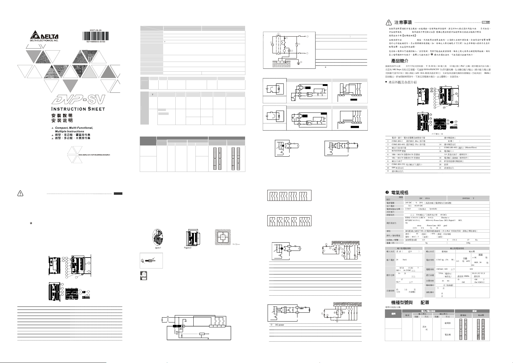
Product Profile and Outline
1
2
3
4
5
6
7
14
10
9
8
13
12
11
70
3903
17
18
16
15
60
20
19
21
Unit: mm
1
POWER/RUN/BAT.LOW/ERROR indicator 12
Extension module connection port
2
COM1(RS-232) receiving communication (Rx) indicator
13
DIN rail (35mm)
3
COM2(RS-485) sending communication (Tx) indicator
14
Extension module fastening clip
4
Input/output indicator 15
COM2 (RS-485) communication port (Master/Slave)
5
RUN/STOP switch 16
Power input port
6
VR0: M1178 enabled/D1178 corresponding value 17
3 P removable terminal (standard component)
7
VR1: M1179enabled/D1179 corresponding value 18
Power input connection cable (standard component)
8
Input/output terminal 19
New high-speed extension module connection port
9
COM1(RS-232) program I/O communication port 20
Nameplate
10
DIN rail clip 21
Direct fastening hole
11
Extension module positioning hole
ENGLISH
Specifications
Model
Item
DVP28SV11R DVP28SV11T
Power supply voltage
24V DC (-15% ~ 20%) (with counter-connection protection on the polarity of DC input power)
Inrush current
Max. 2.2A@24V DC
Power consumption
6W
Insulation resistance
> 5MΩ (all I/O point-to-ground: 500V DC)
Noise immunity
ESD (IEC 61131-2, IEC 61000-4-2): 8KV Air Discharge
EFT (IEC 61131-2, IEC 61000-4-4): Power Line: 2KV; Digital I/O: 1KV,
Analog & Communication I/O: 1KV
Damped-Oscillatory Wave: Power Line: 1KV, Digital I/O: 1KV
RS (IEC 61131-2, IEC 61000-4-3): 26MHz ~ 1GHz, 10V/m
Earth
The diameter of grounding wire shall not be less than that of the wiring terminal of the power.
(When many PLCs are in use at the same time, please make sure every PLC is properly
grounded.)
Operation/storage
Operation: 0ºC ~ 55ºC (temperature); 50 ~ 95% (humidity); pollution degree 2
Storage: -40ºC ~ 70ºC (temperature); 5 ~ 95% (humidity)
Vibration/shock immunity
International standards: IEC61131-2, IEC 68-2-6 (TEST Fc)/IEC61131-2 & IEC 68-2-27
(TEST Ea)
Weight (g)
260g 240g
Type Current
Motion level Responding time
Input
point
DC
(Sink or
Source)
24VDC
5mA
X0 ~ X7,X12 ~
X13,X16 ~ X17
OffOn
> 16.5VDC
X10 ~ X11,X14 ~ X15
OffOn
> 18.5VDC
X0 ~ X17
OnOff
< 8VDC
Approx. 10 ms (can be
adjusted within the range of
10 ~ 60 ms by D1020 and
D1021)
Type Current Voltage Max. loading
Responding
time
Mechanical
life
Electrical life
relay-R
1.5A/1 point
(5A/COM)
250VAC,
> 30VDC
75VA
(inductive)
90 W
(resistive)
Approx.
10 ms
2×10
7
times
(without
load)
1.5×10
5
times (5A
30VDC)
5×10
5
times (3A
120VAC)
3×10
4
times (5A
250VAC)
Max. 10KHz
for Y5, Y7,
Y10 ~ Y13
OffOn
20us
OnOff
30us
Output
point
transist
or-T
General: 0.3A/1
point @40ºC
High-speed: <
1KHz, 0.3A/1 point
@ 40ºC; ≥1KHz,
30mA/1point@40
ºC
30VDC
Max. 200KHz
for Y0, Y1, Y2,
Y3, Y4, Y6
OffOn
0.2us
OnOff
0.2us
- -
Model Name & I/O Configuration
Standard Functional MPU
Input/output specification I/O configuration
Input Output Model
Power
Point
Type Point Type
Relay Transistor Point
DVP28SV11R
Relay
DVP28SV11T
24VDC
16
DC (Sink
Or
Source)
12
Transistor
S/S
X0
X1
X2
X3
X4
X5
X6
X7
S/S
X10
X11
X12
X13
X15
X16
X17
C0
Y0
Y1
Y2
Y3
Y4
Y5
Y6
Y7
Y10
Y11
Y12
Y13
C1
C2
C3
S/S
X0
X1
X2
X3
X4
X5
X6
X7
S/S
X10
X11
X12
X13
X15
X16
X17
C0
Y0
Y1
C1
C2
Y4
Y5
Y6
Y7
Y12
Y13
C3
Y2
Y3
C4
Y10
Y11
Installation & Wiring
4.1 PLC Mounting Arrangements and Wiring Notes
How to install DIN rail:
DVP-PLC can be secured to a cabinet by using the DIN rail of 35mm in height and 7.5mm in depth. When
mounting PLC to DIN rail, be sure to use the end bracket to stop any side-to-side movement of PLC and reduce
the chance of wires being loosen. A small retaining clip is at the bottom of PLC. To secure PLC to DIN rail, place
the clip onto the rail and gently push it up. To remove it, pull the retaining clip down and gently remove PLC from
DIN rail, as shown in figure 1.
How to screw:
Please use M4 screw (see figure 2) according to the dimension of the product. Please install PLC in an
enclosure with sufficient space around it to allow heat dissipation (see figure 3).
90
53.2
70
101
109.4
PLC
D
D
DD
D > 50 mm
Figure 1 Figure 2 (Unit: mm) Figure 3
Wiring:
22-1 6A WG
< 1.5 mm
1. Use 22-16AWG (1.5mm) single or multiple core wire on I/O wiring terminals. The
specification of the terminal is shown in the figure on the left. The PLC terminal
screws shall be tightened to 1.95 kg-cm (1.7 in-lbs).
2. DO NOT place the I/O signal wires and power supply wire in the same wiring duct.
3. Use 60/75 ºC copper wires only.
DO NOT install PLC in an environment with:
Dust, smoke, metallic debris, corrosive or flammable gas
High temperature, humidity
Direct shock and vibration
4.2 Wiring Notes
Power input wiring
The power input of DVP-SV series is DC. When operating SV series, please make sure that:
1. The power is connected to the two terminals, 24V DC and 0V, and the range of power is 20.4 ~ 28.8V DC.
If the power voltage is less than 20.4V DC, PLC will stop running, all outputs will go “Off” and ERROR
indicator will flash continuously.
2. The power shutdown of less than 10 ms will not affect the operation of PLC. However, power shutdown
time that is too long or the drop of power voltage will stop the operation of PLC and all outputs will go “Off”.
When the power supply turns normal again, PLC will automatically return to its operation. (Please be
aware of the latched auxiliary relays and registers inside PLC when programming.)
24V
2A
S/S
X0 X1 X2
20.4V~28.8V
0V
DC/DC 5V
Safety wiring
Since DVP28SV is only compatible with DC power supply, Delta power supply modules (DVPPS01/DVPPS02)
are suitable power supplies for DVP28SV. Users are suggested to install the protection circuit at the power
supply terminal to protect DVPPS01 or DVPPS02.
AC power supply load
Power circuit protection fuse (3A
)
Power indicator
Emergency stop
This button can cut off the system power supply
when accidental emergency takes place.
System circuit isolation device
The device is made of electromagnetic contactor
and relay as the switch to prevent the instability of
system when the power is intermittently supplied.
DVPPS01/DVPPS02 (main processing unit)
Earth
MC
MC
NL
1
1
2
3
4
5
6
7
8
Guard
Limit
MC
Power supply AC: 100 ~ 240V AC, 50/60Hz
Input point wiring
There are two types of DC inputs, SINK and SOURCE.
Input point loop equivalent circuit Wiring loop DC Signal IN
S/S
X0
Sinking
SINK mode
(common port for current
input S/S)
24VDC
24G
X0
S/S
+24V
SINK
+5V
24G S/S X0 X1 X2+24V
Sink Type
Input point loop equivalent circuit Wiring loop DC Signal IN
S/S
X0
Sourcing
SOURCE mode
(common port for current
output S/S)
24VDC
24G
X0
S/S
+24V
SOURCE
+5V
24G S/S X0 X1 X2+24V
Source Type
Output point wiring
Y0
RY
LED
C0
LOAD
POWER
DVP-**-**-11-R
RELAY OUTPUT
DVP-**-**-11-T
TRANSISTOR OUTPUT
LED
Y0
C0
LOAD
< 0.3A
T
R
G
1. DVP-SV series have two output modules, relay and transistor. See “Specifications” for their specifications.
2. Be aware of the connection of shared terminals when wiring output terminals.
3. Output terminals, Y0, Y1, and Y2, of relay models use C0 common port; Y3, Y4, and Y5 use C1 common
port; Y6, Y7, and Y10 use C2 common port; Y11, Y12, and Y13 use C3 common port, as shown in the
next page.
C0 Y0 Y1 Y2 C1 Y3 Y 4 Y5 C2 Y6 Y7 Y10 C3Y11 Y12 Y13
When output points are enabled, their corresponding indicators on the front panel will be on.
4. Output terminals, Y0 and Y1, of transistor models use C0 common port; Y2 and Y3 use C1 common port;
Y4 and Y5 use C 2 common port; Y6 and Y7 use C3 common port; Y10, Y11, Y12 and Y13 use C4
common port, as shown below.
C0
Y0
Y1
C4
Y10
Y11
Y12
C1
Y2
Y3
C2
Y4
Y5
C3
Y6
Y7
Y13
5. Isolation circuit: T he optical coupler is used to isolate signals between the ci rcuit inside PLC and i nput
modules.
Relay (R) contact circuit wiring
Y0
RY
LED
C0
LOAD
POWER
DVP-**-**-**-R
RELAY OUTPUT
2
3
1
5
C0 Y 0 Y1 C1 Y3 Y4
C2
Y6 Y7
4
MC1
MC2
7
10
3
2
8
9
6
R
C
Flywheel diode (SB360 3A 60V): To extend the life span of contact
Emergency stop: Uses external switch
Fuse: Uses 5 ~ 10A fuse at the common port of output contacts to protect the output circuit.
Varistor: To reduce the interference on AC load (R=100~120Ω, C=0.1~0.2uF)
Empty terminal: not in use
DC power supply
Neon indicator
AC power supply
Incandescent light (resistive load)
Manually exclusive output: Uses external circuit and forms an interlock, together with the PLC
internal program, to ensure safety protection in case of any unexpected errors.
Transistor (T) contact circuit wiring
DVP-**-**-**-T
TRANSISTOR OUTPUT
LED
Y0
C0
LOAD
觸
發
回
路
0
00
0.
..
.5
55
5A
AA
A以下
以下以下
以下
MC1
MC2
2
3
1
C0 Y0 Y1 C4 Y 10 Y1 1 Y1 2 Y1 3
5
4
5
3
4
DC power supply
Emergency stop
Circuit protection fuse
Flywheel diode (SB360 3A 60V) + inductive load
Manually exclusive output: Uses external circuit and forms an interlock, together with the PLC
internal program, to ensure safety protection in case of any unexpected errors.
注意事項
本使用說明書僅提供電氣規格、功能規格、安裝配線部份說明,其它詳細之程式設計及指令與
EH
系列相容,
詳細說明請見
DVP-PLC
應用技術手冊【程式篇】,選購之週邊裝置詳細說明請見該產品隨機手冊或
DVP-PLC
應用技術手冊【特殊模組篇】。
本機為開放型
(OPEN TYPE)
機殼,因此使用者使用本機時,必須將之安裝於具防塵、防潮及免於電擊
/
衝擊
意外之外殼配線箱內。另必須具備保護措施(如:特殊之工具或鑰匙才可打開)防止非維護人員操作或意外
衝擊本體,造成危險及損壞。
交流輸入電源不可連接於輸入/出信號端,否則可能造成嚴重損壞,請在上電之前再次確認電源配線。請勿
在上電時觸摸任何端子。本體上之接地端子
務必正確的接地,可提高產品抗雜訊能力。
產品簡介
謝謝您採用台達
DVP
系列可程式控制器。
SV
為
28
點(
16
輸入點
+ 12
輸出點)
PLC
主機,提供豐富的指令集,
並具有
16K Steps
的程式記憶體,可連接
SS/SA/SX/SC/SV
全系列擴充機,包含數位輸入
/
輸出(最大輸入
/
輸出擴
充點數可達
512
點)、類比模組(
A/D
、
D/A
轉換及溫度單元)
及新型高速擴充機等各類機型。四組高速(
200KHz
)
脈波輸出、新增兩軸補間指令,可滿足各種應用場合,並且體積小,安裝容易。
產品外觀及各部介紹
1
2
3
4
5
6
7
14
10
9
8
13
12
11
70
3903
17
18
16
15
60
20
19
21
尺寸單位:
mm
1
電源、運行、電池低電壓及錯誤指示燈
12
擴充機連接口
2 COM1 (RS-232)
通訊接收
(Rx)
指示燈
13
DIN
軌糟(
35mm
)
3 COM2 (RS-485)
通訊傳送
(Tx)
指示燈
14
擴充機固定扣
4
輸出
/
入點指示燈
15
COM2 (RS-485)
通訊口
(Master/Slave)
5
RUN/STOP
開關
16
電源輸入口
6 VR0
:
M1178
啟動
/D1178
對應值
17
3 P
脫落式端子(標準附件)
7 VR1
:
M1179
啟動
/D1179
對應值
18
電源輸入連接線(標準附件)
8
輸出
/
入端子
19
新型高速擴充機連接口
9
COM1 (RS-232)
程式輸出
/
入通訊口
20
銘牌
10
DIN
軌固定扣
21
直接固定孔
11
擴充機定位孔
繁體中文
繁體中文繁體中文
繁體中文
電氣規格
機種
項目
DVP28SV11R DVP28SV11T
電源電壓
24V DC (-15% ~ 20%)
(具直流輸入電源極性反接保護)
突入電流
MAX 2.2A @24V DC
電源保險絲容量
2.5A/30V DC
,可恢復式
(Polyswitch)
消耗電力
6W
絕緣阻抗
5 MΩ
以上
(
所有輸出/入點對地之間
500V DC)
雜訊免疫力
ESD(IEC 61131-2, IEC 61000-4-2): 8KV Air Discharge
EFT(IEC 61131-2, IEC 61000-4-4): Power Line: 2KV, Digital I/O: 1KV,
Analog & Communication I/O: 1KV
Damped-Oscillatory Wave: Power Line: 1KV, Digital I/O: 1KV
RS(IEC 61131-2, IEC 61000-4-3): 26MHz ~ 1GHz, 10V/m
接地
接地配線之線徑不得小於電源端配線線徑(多台
PLC
同時使用時,請務必單點接地)
操作/儲存環境
操作:
0ºC ~ 55ºC
(溫度)
50 ~ 95%
(濕度)污染等級
2
儲存:
-40ºC ~ 70ºC
(溫度)
5 ~ 95%
(濕度)
耐振動/衝擊
國際標準規範
IEC61131-2, IEC 68-2-6 (TEST Fc)/ IEC61131-2 & IEC 68-2-27 (TEST Ea)
重量(約
, g
)
260g 240g
輸入點電氣規格
輸出點電氣規格
輸入形式
直
流(
SINK
或
SOURCE
)
輸出形式
繼電器
-R
電晶體
-T
輸入電流
24VDC 5mA
電流規格
1.5A/1
點(
5A/COM
)
一般
0.3A/1
點
@40ºC
高速
> 1KHz, 0.3A/1
點
@40ºC
≥ 1KHz, 30mA/1
點
@40ºC
X0~X7,X12~X13,X16~X17
OffOn 16.5VDC
以上
電壓規格
250VAC, 30VDC
以下
30VDC
X10~X11,X14~X15
OffOn 18.5VDC
以上
最大負載
75VA
(電感性)
90W
(電阻性)
Y5,Y7,Y10 ~ Y13
最高為
10KHz
Y0,Y1,Y2,Y3,Y4,Y6
最高為
200KHz
動作位準
X0~X17
OnOff 8VDC
以下
反應時間
約
10 ms
OffOn 20us
OnOff 30us
OffOn 0.2us
OnOff 0.2us
機械壽命
2×10
7
次
(
無負載
)
-
反應時間
約
10 ms
(由
D1020
及
D1021
可作
10~60 ms
的調整)
接點壽命
1.
5
×10
5
次
(5A
30VDC)
5×10
5
次
(3A 120VAC)
3×10
4
次
(5A 250VAC)
-
機種型號與
I/O
配置
標準功能型主機
輸入
輸入輸入
輸入/
//
/輸出規格
輸出規格輸出規格
輸出規格
I/O
配置
配置配置
配置
輸入單元
輸出單元
機種
機種機種
機種
電源
點數
形式
點數
形式
繼電器
電晶體
DVP28SV11R
繼電器
DVP28SV11T
24VDC
16
直流
Sink
或
Source
12
電晶體
S/S
X0
X1
X2
X3
X4
X5
X6
X7
S/S
X10
X11
X12
X13
X15
X16
X17
C0
Y0
Y1
Y2
Y3
Y4
Y5
Y6
Y7
Y10
Y11
Y12
Y13
C1
C2
C3
S/S
X0
X1
X2
X3
X4
X5
X6
X7
S/S
X10
X11
X12
X13
X15
X16
X17
C0
Y0
Y1
C1
C2
Y4
Y5
Y6
Y7
Y12
Y13
C3
Y2
Y3
C4
Y10
Y11
 Loading...