

Page 1
F250/300/400
F250/300/400
• Istruzioni per l’uso . . . . . . . . . . . .pag. 6
• Use and maintenance manual . . . .pag. 18
• Mode d’emploi et d’entretien . . . . .pag. 30
• Betriebsanleitung . . . . . . . . . . . . .pag. 42
• Gebruiksaanwijzing . . . . . . . . . . . . . .pag. 54
• Instrucciones de uso . . . . . . . . . .pag. 66
• Manual de instruções . . . . . . . . . .pag. 78
• ГдизЭеч штЬуич лбй ущофЬтиуич . . .óåì. 90
I 8-08-2001 9:27 Pagina 1
Page 2
Gentile Cliente,
La ringraziamo per aver scelto un prodotto De’Longhi, il leader mondiale
nella costruzione dei climatizzatori portatili. Anni di esperienza in tutto il
mondo ci consentono di migliorare costantemente la qualità e le prestazioni di Pinguino e SuperPinguino. Siamo certi che rimarrà subito soddisfatto del suo acquisto e che godrà a lungo del fresco benessere che Pinguino e SuperPinguino creano. La preghiamo di dedicare un po’ del suo
tempo alla lettura di questo libretto di istruzioni, e di conservarlo con cura.
In questo modo, potrà utilizzare Pinguino nelle condizioni di massima efficacia e serenità.
Dear Customer,
Thank you for having purchased an appliance made by De’ Longhi, the
international leader in portable air conditioning units. Thanks to our years
of experience all around the world we are constantly improving the quality and performance of Pinguino. We are confident that you will be satisfied with your purchase and enjoy the cool comfort created by the Pinguino for many years to come. You should spend some time reading this
instruction manual and keep it handy to refer to in order to use your Pinguino in conditions of maximum efficiency and peace of mind.
Verehrter Kunde
Wir danken Ihnen, daß Sie sich für ein Produkt von De'Longhi entschieden haben,
dem weltweiten Marktführer bei der Herstellung von tragbaren Klimageräten.
Jahre der Erfahrung in der gesamten Welt ermöglichen uns, die Qualität von Pinguino und SuperPinguino konstant zu verbessern. Wir sind sicher, daß Sie mit Ihrem
Kauf zufrieden sein werden und das frische Wohlbefinden, das Pinguino und
SuperPinguino verbreiten, über eine lange Zeit genießen werden. Wir bitten Sie,
sich etwas Zeit zu nehmen, um diese Gebrauchsanweisung durchzulesen und Sie
danach sorgfältig aufzubewahren. Auf diese Weise haben Sie die Gewißheit, mit
Pinguino die größte Leistungsfähigkeit und Sicherheit zu erzielen.
Chère Cliente, Cher Client,
Nous vous remercions d’avoir choisi un produit De’Longhi, le plus important
fabricant mondial de climatiseurs portables. Des années d’expérience
dans le monde entier nous permettent d’améliorer constamment la qualité
et les performances de Pinguino. Nous sommes certains que vous serez
immédiatement satisfait de votre achat et que vous profiterez pendant
longtemps de la fraîcheur et du bien-être que Pinguino cré. Nous vous
prions de bien vouloir consacrer un peu de temps à la lecture de ce mode
d’emploi et de le conserver soigneusement. Ses conseils vous permettront
d’obtenir les meilleurs résultats de votre Pinguino en toute sécurité.
I 8-08-2001 9:27 Pagina 2
Page 3
Geachte Client,
Wij danken u voor het kiezen van een produkt De'Longhi, nummer één op
wereldniveau op het gebied van de constructie van draagbare airconditioners. Jaren ervaring over de hele wereld maken het ons mogelijk de kwaliteit en de prestaties van Pinguino en SuperPinguino constant te verbeteren.
Wij zijn er zeker van dat u tevreden zult zijn met uw aankoop en dat u voor
lange tijd zult genieten van het frisse welzijn dat Pinguino en Superpinguino
in staat zijn te creëren. Wij verzoeken u enige tijd te besteden aan het lezen
van dit instructieboekje, en dit goed te bewaren. Op deze manier zult u Pinguino kunnen gebruiken met de meeste efficiëntie en zonder problemen.
Estimado Cliente
Le agradecemos por haber elegido un producto De’ Longhi, líder mundial en la fabricación de los acondicionadores portátiles. Años de experiencia en todo el mundo nos permiten mejorar constantemente la calidad y las prestaciones de Pingüino. Estamos seguros que quedará inmediatamente satisfecho de su compra y que gozará por largo tiempo el
fresco bienestar que da Pingüino. Le pedimos que dedique un poco de
su tiempo a la lectura de este manual de instrucciones y de guardarlo
con cuidado. De este modo, podrá usar Pingüino en condiciones de
máxima eficacia y serenidad.
Prezado Cliente
agradecemos por ter escolhido um produto Dé Longhi, o líder mundial na
fabricação dos condicionadores portáteis. Anos de experiência em todo
o mundo permitem-nos melhorar constantemente a qualidade e os
desempenhos dos aparelhos Pinguino. Temos certeza de que ficará logo
satisfeito com a sua compra e que usufruirá por muito tempo do fresco
bem-estar que Pinguino e Super Pinguino oferecem. Por favor, dedique
um pouco do seu tempo à leitura deste manual de instruções e conserve-o com cuidado. Desta forma, poderá utilizar o aparelho Pinguino com
a máxima eficácia e serenidade.
AзбрифЫ ремАфи,
ªбч ещшбтйуфпане рпщ ерймЫкбфе Ыоб ртпыЮо De' Longhi, фич незбмафетич
ефбйтЭбч лбфбулещЬч жптифсо лмйнбфйуфйлсо. ¸ рпмщефЬч нбч енрейтЭб уе Юмп
фпо лЮунп, нбч ерйфтЫрей фи ущоешЬ вемфЭцуи фич рпйЮфифбч лбй фцо
ерйдЮуецо фпщ Pinguino лбй фпщ SuperPinguino.
¶Энбуфе вЫвбйпй Юфй хб неЭоефе брЮмщфб йлбопрпйинЫопй брЮ фио бзптА убч лбй
Юфй хб брпмбауефе зйб рпммА штЮойб фи дтпуетЬ ещекЭб рпщ ртпужЫтпщо фб
лмйнбфйуфйлА Pinguino лбй SuperPinguino.
ªбч рбтблбмпане об бжйетсуефе мЭзп брЮ фп штЮоп убч уфио боАзоцуи фпщ
рбтЮофпч езшейтйдЭпщ пдизйсо лбй об фп жщмАкефе ртпуелфйлА. »е фпо фтЮрп
бщфЮ, нрптеЭфе об штиуйнпрпйЬуефе фп Pinguino уе ущохЬлеч нЫзйуфич
брЮдпуич лбй бужАмейбч.
I 8-08-2001 9:27 Pagina 3
Page 4
Mod. F400
Mod. F250
F300
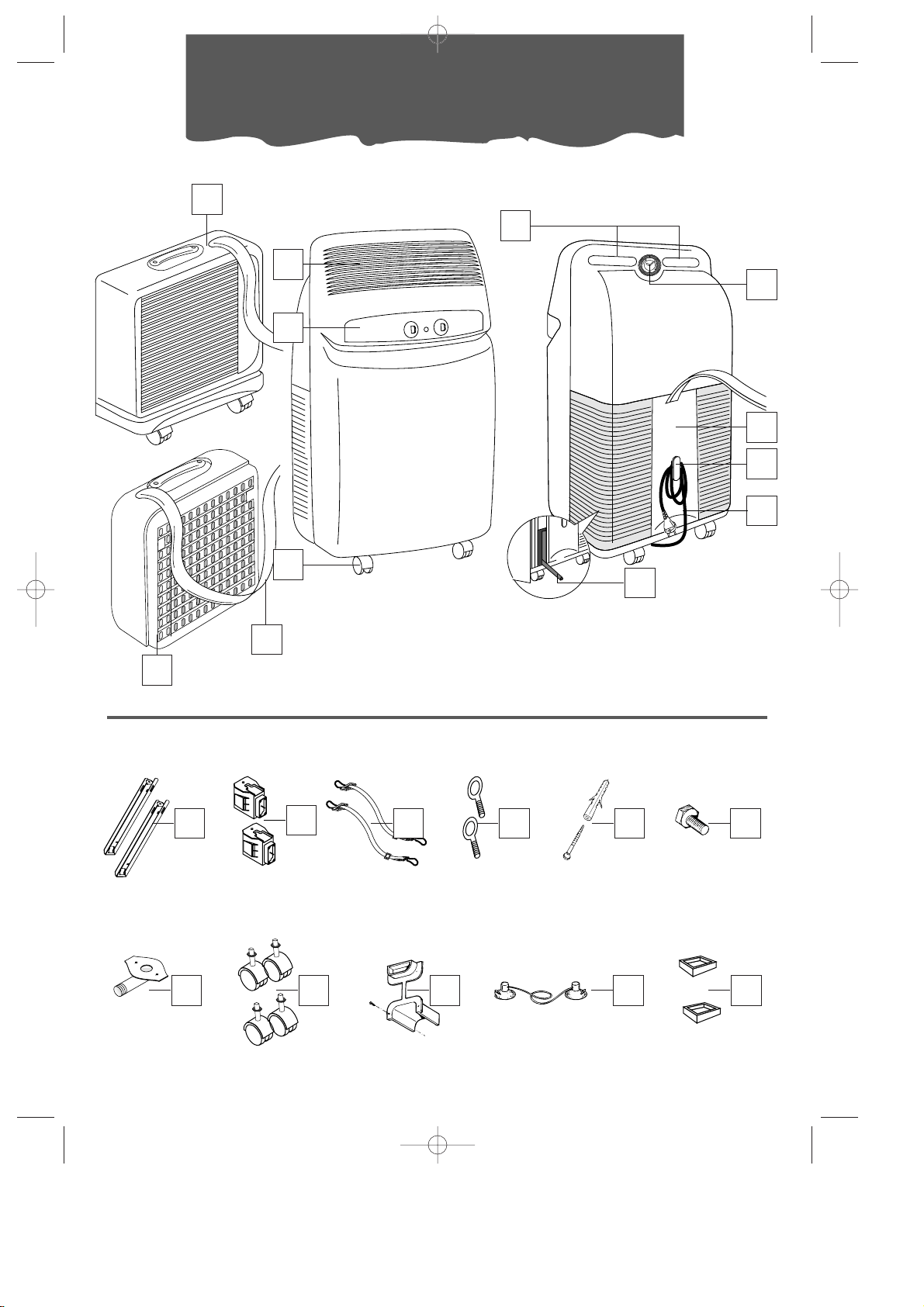
Descrizione • Description • Description • Beschreibung •
Beschrijving • Descriptción • Descrição • ¦етйзтбжЬ
2
3
5
1
4
6
7
9
11
10
12 15 16 1714
ACCESSORI
• ACCESSORY-SET
• ACCESSOIRES
• ZUBEHÖR •
ACCESSOIRES
• ACCESORIOS •
ACESSÓRIOS •
°¥¶ªÃË°Ä
13
18 20 21 2219
8
1
I 8-08-2001 9:27 Pagina 4
Page 5
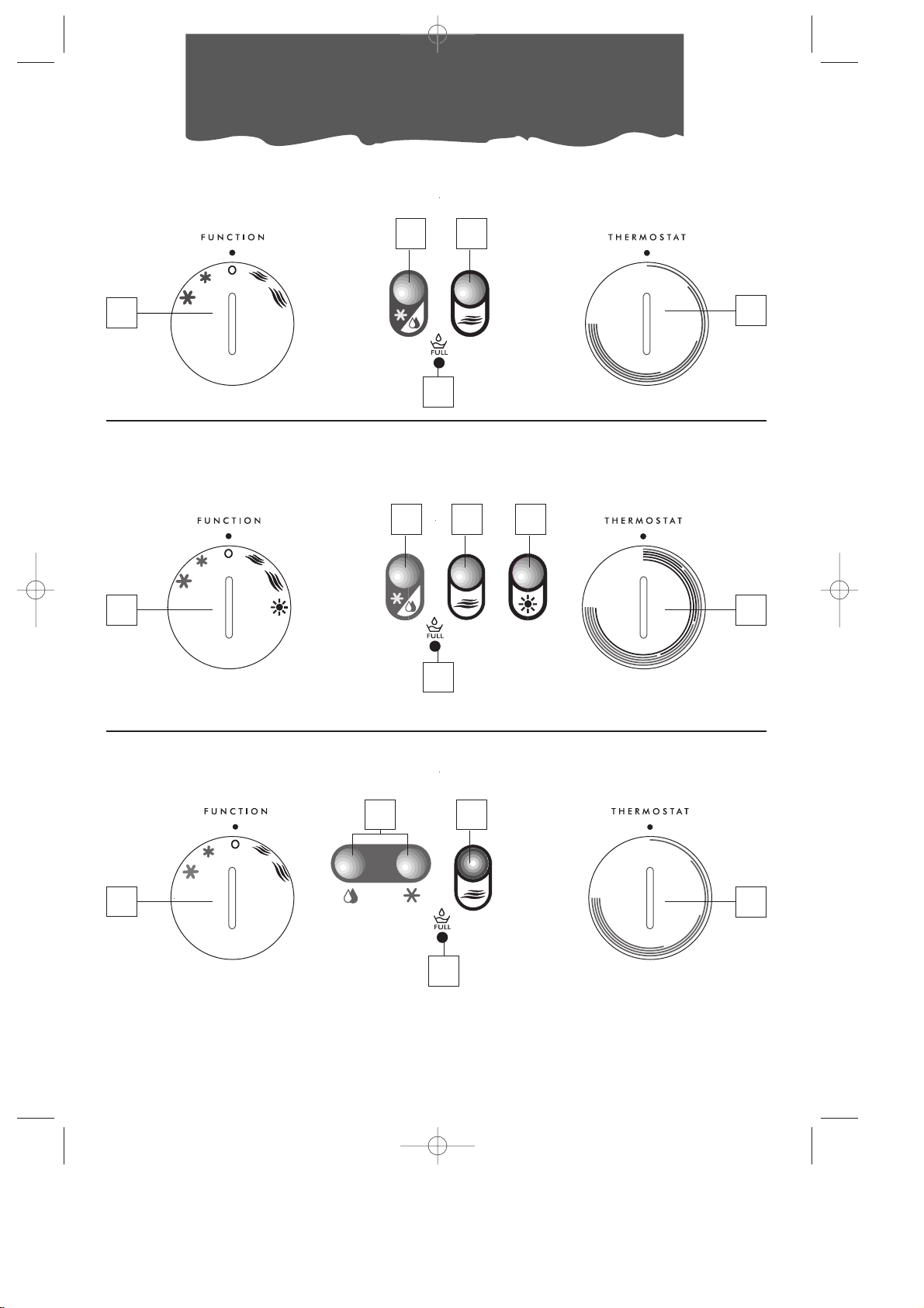
Pannello comandi •
Control panel
• Panneau de commande •
Bedienungsblende
• Bedieningspaneel •
Tablero de mandos
•
Painel de comandos •
̶¹Ä¹ªÆ¸Ä¹°
Mod. F250
Mod. F400
Mod. F300
23
23
23
24 25
24 25 26
24 25
27
27
27
28
28
28
I 8-08-2001 9:27 Pagina 5
Page 6

6
Avvertenze
• Questo apparecchio è stato costruito per condizionare gli ambienti domestici e non deve
essere adoperato per altri scopi.
• É pericoloso modificare o alterare in qualsiasi
modo le caratteristiche dell’apparecchio.
• L’apparecchio deve essere installato secondo le
regole impiantistiche nazionali.
• Per eventuali riparazioni, rivolgetevi sempre ed
esclusivamente ai Centri di Assistenza Tecnica
autorizzati dalla Casa Costruttrice. Le riparazioni
effettuate da personale incompetente possono
essere pericolose.
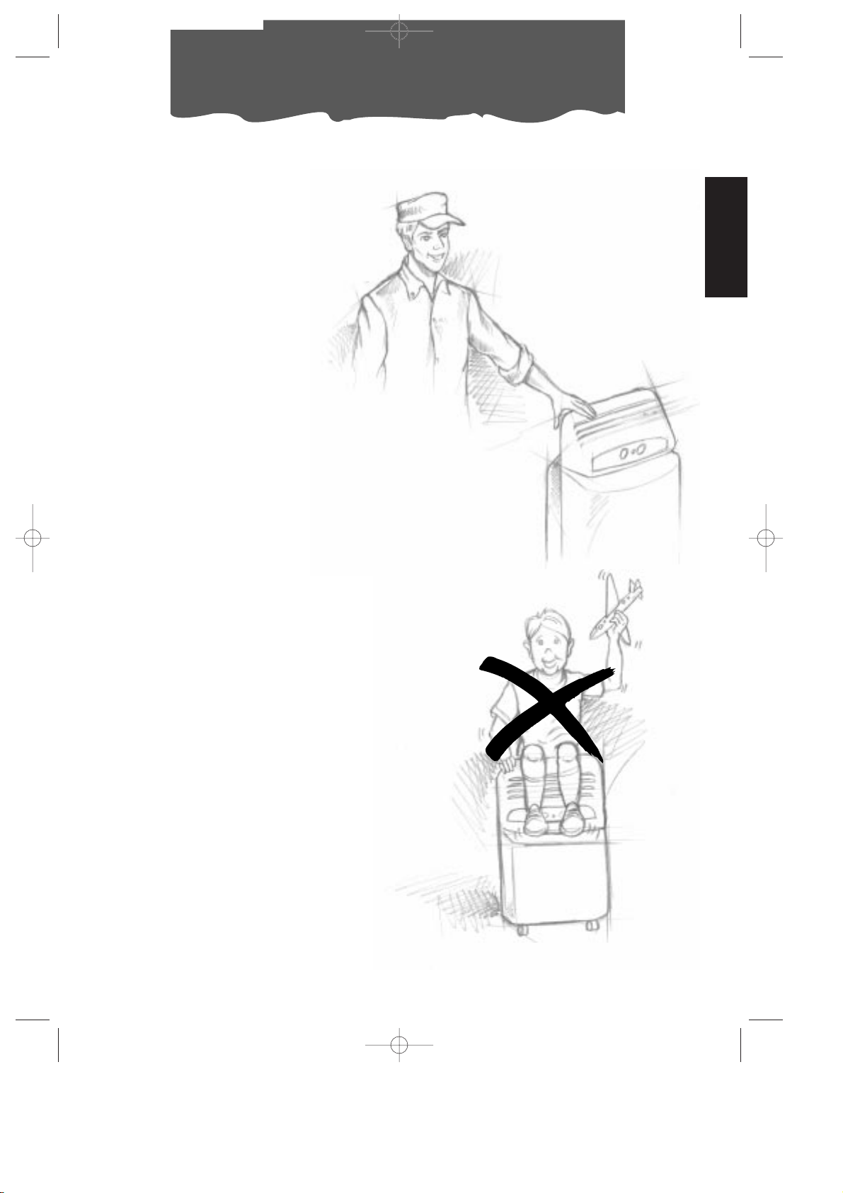
• Questo apparecchio deve essere usato esclusivamente da adulti; non permettete che i bambini giochino con esso.
• Questo apparecchio deve essere collegato ad
un’efficace impianto di “terra”. Fate controllare
l’impianto elettrico da un elettricista qualificato.
• Evitate l’utilizzo di prolunghe per il cavo di alimentazione elettrica.
• Prima di ogni operazione di pulizia o di manutenzione, staccate sempre la spina dalla presa
di corrente.
• Non tirate il cavo di alimentazione elettrica per
spostare il prodotto.
• Non installate l’apparecchio in ambienti dove
l’aria può contenere gas, olio, zolfo o in prossimità di fonti di calore.
• Attendete sempre almeno 3 minuti prima di riavviare l’apparecchio dopo uno spegnimento.
• Non appoggiate oggetti pesanti o caldi sopra
l’apparecchio.
• Pulite i filtri antibatterici almeno ogni settimana.
• Evitate di utilizzare apparecchi di riscaldamento
in prossimità del climatizzatore.
• In caso di trasporto, l’apparecchio deve restare in
posizione verticale o adagiato su un fianco.
Prima di un trasporto vuotate la bacinella dell’acqua di condensa e la vaschetta. Dopo un
trasporto, attendete almeno 1 ora prima di
avviare l’apparecchio.
• I materiali utilizzati per l’imballaggio sono riciclabili.
Si consiglia quindi di riporli negli appositi contenitori per la raccolta differenziata.
I 8-08-2001 9:27 Pagina 6
Page 7
7
Nella stagione estiva, le condizioni di benessere sono raggiunte con una temperatura com-
presa tra i 24 e i 27°C e con una umidità relativa attorno al 50%.
Il climatizzatore è una macchina che sottrae umidità e calore dall’ambiente in cui è collocata.
Rispetto ai modelli da installazione, i climatizzatori portatili hanno il vantaggio di poter essere spostati da una stanza all’altra di una casa, e di essere trasferibili da un edificio all’altro.
L’aria calda della vostra stanza viene fatta
passare attraverso una batteria raffreddata da un gas refrigerante. In tal
modo cede calore e umidità in
eccesso prima di venire re-immessa nell’ambiente.
Nei modelli monoblocco (Pinguino) una piccola parte di
questa aria viene utilizzata
per raffreddare il gas refrigerante e quindi, divenuta
calda e umida, viene rilasciata all’esterno.
Nei modelli con valigetta
(SuperPinguino) il circuito
si raffredda sfruttando l’aria esterna.
Ogni Pinguino e SuperPinguino può essere usato
anche in funzione di sola
ventilazione.
Per approfondimenti e chiarimenti, potete rivolgervi al:
oppure contattare il nostro sito internet:
www.delonghi.it
Cosa sono Pinguino e SuperPinguino
ITALIANO
I 8-08-2001 9:27 Pagina 7
Page 8
UTILIZZO DEI RACCORDI RAPIDI
(solo mod. F400 e F300)
In aggiunta ai metodi precedentemente
descritti, la guaina che collega l’unità esterna a quella interna può passare attraverso un
foro del diametro di 6 cm. circa, praticato in
una parete che comunica con l’esterno.
8
Predisposizione all’uso
NOTA: La distanza dell’apparecchio dalle
pareti deve essere di almeno 30 cm.
b) Attraverso una piccola fessura (5.5 cm x
2,5 cm) ricavata nella parte inferiore di
una porta o nel telaio di una finestra, utilizzando la cornice per guaina in dotazione.
20
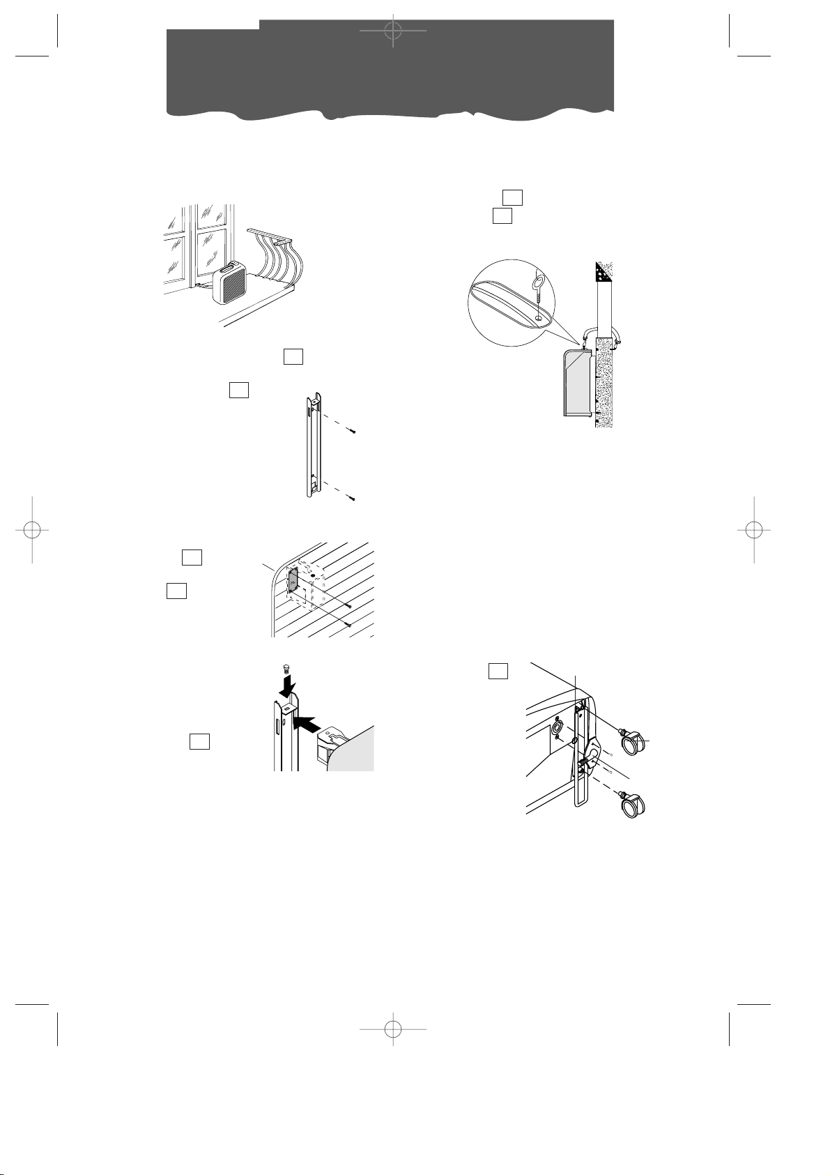
DISPOSIZIONE DELL’UNITA’ INTERNA
Installare l’apparecchio all’interno del locale
da condizionare. In genere vicino una finestra
o in ogni caso vicino ad una parete perimetrale. L’unità interna deve essere posizionata
“in piano”, servirsi anche dei fermaruote
in dotazione. L’unità interna non deve avere
ostacoli sulla zona di aspirazione (griglia di
aspirazione ) e nella zona di emissione (griglia di uscita ).
2
8
22
cm 30
cm 30
cm 30
DISPOSIZIONE DELLA GUAINA DI COLLEGAMENTO
La guaina che collega l’unità esterna a
quella interna può passare:
a) Da una fessura di finestra o porta socchiu-
sa; utilizzate le ventose perché non si
spalanchi.
21
4
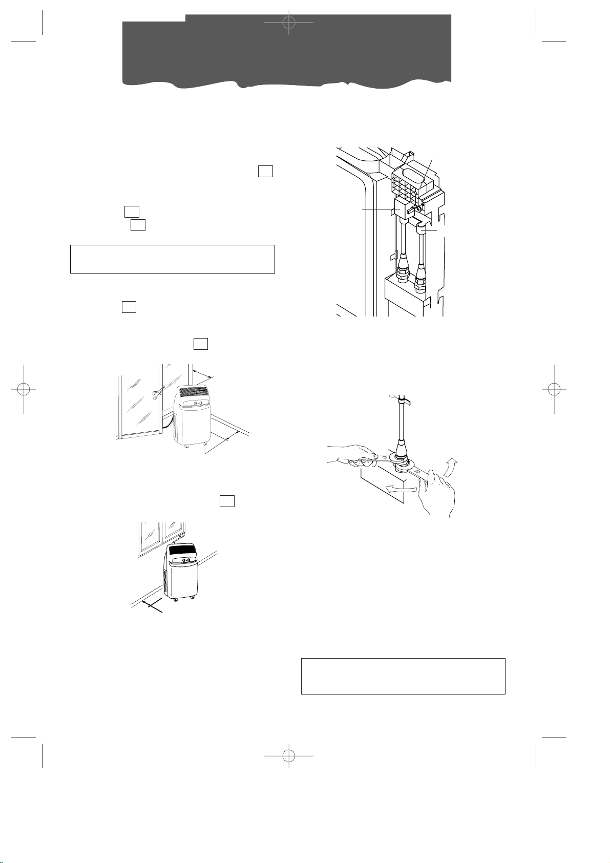
FERMAGUAINA
PROTEZIONE
BLOCCHETTO DI
CONNESSIONE
ELETTRICA
CAVALLOTTO
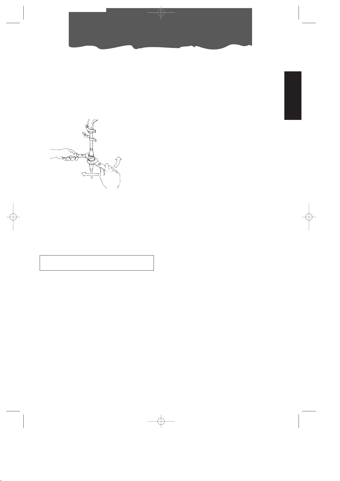
1) Togliere la spina dalla presa di corrente.
2) Togliere la maniglia svitando le 2 viti metriche, quindi sfilare la facciata.
3) Togliere il cavallotto svitando le 2 viti metriche.
4) Togliere il fermaguaina svitando le 2 viti
metriche.
5) Impiegando una chiave inglese da 24, svitare il bocchettone girevole del raccordo.
Contemporaneamente, con una chiave
da 21, tenere ferma l’estremità del tubo
flessibile. (Ripetere l’operazione per il
secondo bocchettone utilizzando una
chiave da 24 e una da 19).
6) Scollegare il tubo di condensa dal portagomma.
7) Svitare le 2 viti autofilettanti della protezione e disinnestare il blocchetto di connessione elettrica.
Evitare le curve troppo secche alla guaina
di collegamento.
Raccordi rapidi nel mod. F400
In quest’ultimo caso si dovranno staccare i
collegamenti dell’unità esterna operando
come segue:
I 8-08-2001 9:27 Pagina 8
Page 9
9
ITALIANO
Predisposizione all’uso
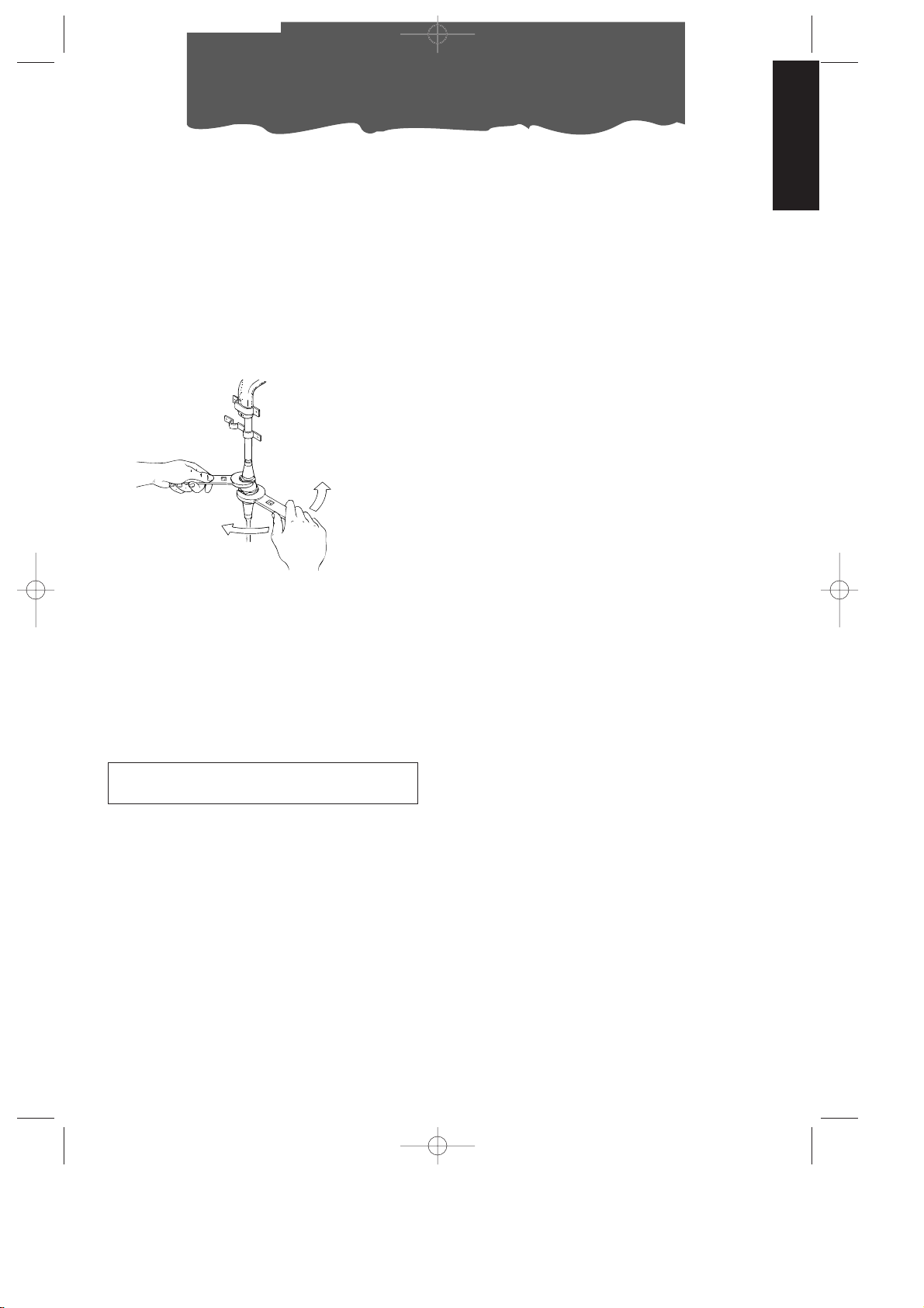
Raccordi rapidi nel mod. F300
In quest’ultimo caso si dovranno staccare i
collegamenti del mobiletto interno operando
come segue:
1) Togliere la spina dalla presa di corrente.
2) Togliere i filtri posti sul lato
3) Togliere lo sportellino posteriore dello
schienale svitando le 2 viti.
4) Togliere i cavallotti in lamiera che fissano i
tubi della macchina (n°2).
5) Impiegando una chiave inglese da 24, svitare il bocchettone girevole del raccordo.
Contemporaneamente, con una chiave
da 21, tenere ferma l’estremità del tubo
flessibile. (Ripetere l’operazione per il
secondo bocchettone utilizzando una
chiave da 24 e una da 19).
6) Scollegare il tubo di condensa dal portagomma.
7) Disinnestare il blocchetto di connessione
elettrica.
Evitare le curve troppo secche alla guaina
di collegamento.
Ricollegare la guaina nei mod. F400 e F300
Per ricollegare le estremità della guaina di
collegamento, precedentemente staccata,
all’unità interna si dovranno ripetere le operazioni 1, 2, 3, 4, 5, 6 e 7 in senso inverso, osservando le seguenti precauzioni:
• Prima di far passare la guaina attraverso il
foro del muro si consiglia di proteggere le
estremità filettate dei raccordi rapidi con
del nastro isolante o simili.
• Imboccare i 2 raccordi frigoriferi superiori
ai 2 inferiori e avvitarli a mano per alcuni
giri controllando che siano bene imboccati, e stringere successivamente con le
chiavi usate precedentemente.
• Dopo aver collegato i due raccordi frigoriferi, fissare i cavallotti.
• Verificare la tenuta dei collegamenti frigoriferi bagnando i giunti con un po’ di
acqua saponata. Non si deve notare formazione di bolle di sapone.
Attenzione
É consigliabile far effettuare le operazioni di
scollegamento e collegamenti dei raccordi
rapidi da personale qualificato.
I 8-08-2001 9:27 Pagina 9
Page 10
10
Predisposizione all’uso
DISPOSIZIONE DELL’ UNITA’ ESTERNA
L’unità esterna può essere appoggiata su
una terrazza o balcone. In questo caso non è
necessario l’uso delle staffe.
L’unità esterna può essere appesa ad un
muro con le apposite staffe . In questo
caso, procedere come segue:
1) fissare la staffa a
muro facendo attenzione che sia posizionata
come indicato in figura
(per la foratura, avvalersi della dima ricavata sul
coperchio in polistirolo
dell’imballo);
2) avvitare i blocchetti
supporto all’unità
esterna con le viti
M4mm in dotazione (facendo attenzione
a posizionarli con il foro
per la vite sulla parte
superiore;
3) agganciare quindi l’unità esterna alle staffe
fissandola, poi con la
vite M6mm .
17
17
13
12
12
In alternativa per installazioni provvisorie, è
possibile sospendere l’unità esterna come
indicato in figura. In questo caso si utilizzeranno le cinghie in dotazione agganciate
agli occhielli ; prima di inserire gli occhielli, togliere i tappi in gomma.
L’unità esterna può essere installata sopra o
allo stesso livello dell’unità interna, purché il
dislivello non superi 1,5 m.
L’unità esterna non deve avere ostacoli né
sull’aspirazione né sulla mandata d’aria.
La distanza minima tra lo schienale e la parete deve essere di 6 cm.
L'acqua di condensa che si forma durante il
funzionamento in condizionamento (funzionamento estivo) viene in parte smaltita per
evaporazione dall'unità esterna.
La condensa residua esce dal foro del basamento dell'unità esterna. É possibile utilizzare il
raccordo drenaggio
condensa per
far defluire la
condensa con
un comune
tubo in gomma
(non in dotazione). Il raccordo
di drenaggio
deve essere
montato sul
basamento dell'unità esterna (vedi figura).
É consigliabile proteggere l’unità esterna da
pioggia, neve, da gocciolamenti dai tetti e
dal sole.
18
15
14
1
2
Ruota
Raccordo
Guarnizione
I 8-08-2001 9:27 Pagina 10
Page 11
11
ITALIANO
Accensione e selezione delle funzioni
COLLEGAMENTO ALLA RETE ELETTRICA E
ACCENSIONE DELL’APPARECCHIO
1. Prima di collegare la spina alla presa di corrente, bisogna verificare che:
• la tensione di rete sia conforme al valore
indicato nella targa caratteristiche posta
sul retro della macchina;
• la presa e la linea di alimentazione elettrica siano dimensionate per sopportare il
carico richiesto;
• la presa sia del tipo adatto alla spina, altrimenti far sostituire la presa stessa;
• la presa sia collegata con un efficace
impianto di terra.
La casa costruttrice
declina ogni responsabilità nel caso questa norma antinfortunistica non fosse
rispettata.
12
6
9
1
0
STOP
MANUALE
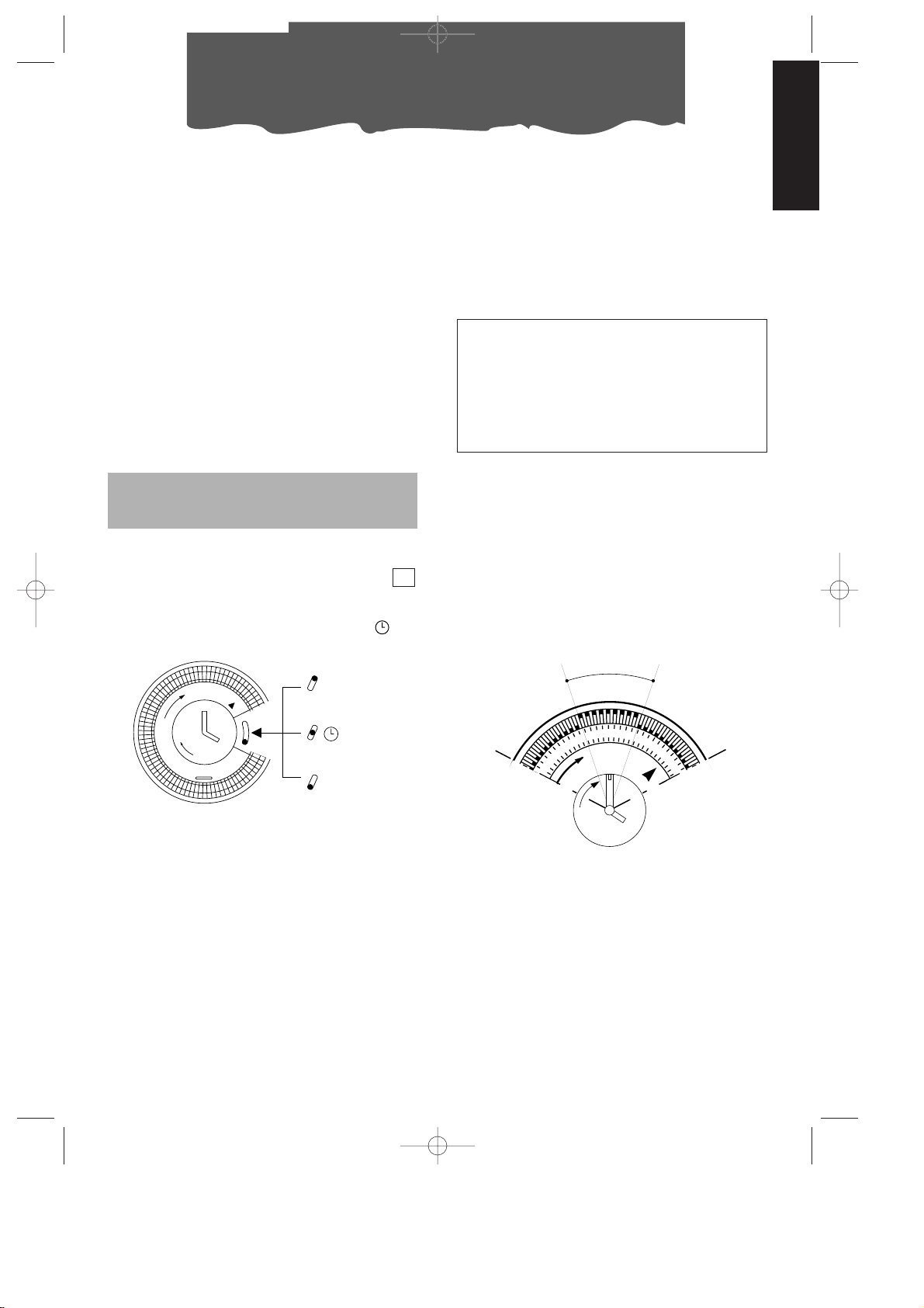
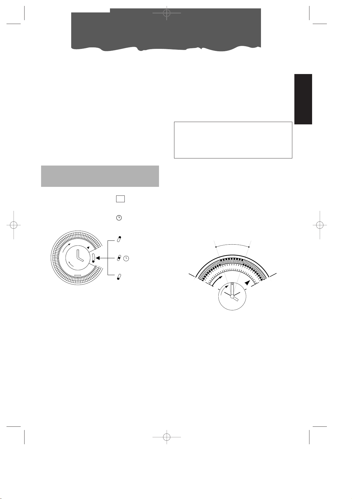
TIMER: REGOLAZIONE DELL’ORA
Il programmatore/timer, come tutti gli orologi,
deve essere regolato sull’ora esatta. Supponendo che siano le 16 ruotare le lancette in
senso orario (seguire il senso della freccia)
fino a impostare le ore 16.
N.B.: Mai ruotare il quadrante in senso opposto!
TIMER: PROGRAMMAZIONE
1) Impostare i periodi di funzionamento spingendo verso l’esterno tutti i dentini compresi nell’intervallo desiderato (ogni dentino sono 15 minuti).
3) Verificare che il timer indichi l’ora esatta
(vedi regolazione dell’ora).
4) Scegliere la funzione desiderata seguendo le istruzioni della pagina seguente.
Il timer è un orologio elettrico e funziona
solo finché la spina è collegata alla rete
elettrica. Ogniqualvolta la spina viene
staccata o manca la corrente, il timer si
ferma (l’orologio rimane “indietro”) e può
essere necessaria una nuova regolazione
dell’ora.
9
8
12
7
4
Periodo di funzionamento
Esempio:
dalle 7 alle 9.
Così predisposto l’apparecchio ripeterà ogni
giorno il programma prefissato.
N.B.: Nel caso si desideri escludere il funzionamento “con timer”, non è necessario variare
il programma; è sufficiente portare l’interruttore sulla posizione
1 (manuale).
2. Prima di impostare la funzione desiderata,
verificate che l’interruttore posto sul timer
sia sulla posizione
1 (manuale).
Se desiderate utilizzare il timer, posizionate
l’interruttore sulla posizione intermedia .
7
Il cavo di alimentazione deve essere sostituito solo da personale tecnico specializzato.
I 8-08-2001 9:27 Pagina 11
Page 12
12
Selezione delle funzioni
COME CLIMATIZZARE
A climatizzatore spento, Il selettore di funzioni
è in posizione “
●●”. Per farlo operare in
funzione climatizzazione, procedere come
segue:
1. Ruotate la manopola selettore funzioni in
senso orario:
• Posizionando il simbolo cristallo grande in corrispondenza dell'indice di riferimento l'apparecchio opererà in funzione
climatizzazione alla massima velocità di
ventilazione
• Posizionando il simbolo cristallo piccolo
in corrispondenza dell'indice di riferimento l'apparecchio opererà in funzione
climatizzazione alla minima velocità di
ventilazione.
2. Scegliete ora la temperatura desiderata
ruotando la manopola termostato ambiente.
Nota
La temperatura non è espressa in gradi. Vi
suggeriamo pertanto di ruotate la manopola
termostato ambiente sulla posizione di massimo freddo.; quando la temperatura ottenuta
nell’ambiente sarà quella di comfort desiderato, potrete ruotare
lentamente la manopo-
la del termostato in senso orario fino a quando il termostato interverrà spegnendo il funzionamento. Così facendo avrete programmato l’apparecchio sull’esatto grado di
comfort che il termostato manterrà automaticamente consentendoVi al tempo stesso un
notevole risparmio energetico. Ogni volta
che il climatizzatore raggiunge la temperatura obiettivo, continuerà ad operare in funzione di sola ventilazione.
23
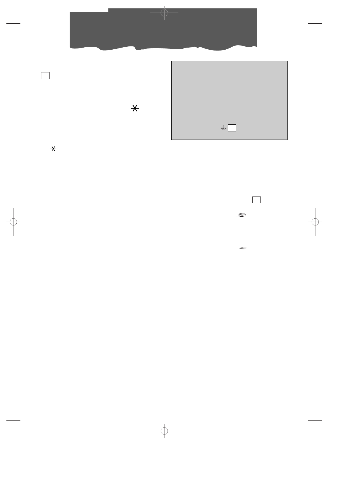
QUESTO APPARECCHIO UTILIZZA UN
ESCLUSIVO SISTEMA DI RICICLO DELLA
CONDENSA PER SMALTIRE L’ECCESSO DI
UMIDITÀ.
IN CONDIZIONI NORMALI, LA CONDENSA
VIENE SMALTITA AUTOMATICAMENTE.
IN CONDIZIONI DI ELEVATA UMIDITÀ POTRÀ
ESSERCI UN ECCESSO DI CONDENSA
NELLA TANICA SEGNALATO DALL’ACCENSIONE DELLA SPIA . IN QUESTO CASO
SARÀ SUFFICIENTE SVUOTARE LA TANICA.
28
COME PURIFICARE VENTILANDO
Il vostro climatizzatore è dotato di due speciali filtri elettrostatici ad altissima efficienza,
FILTRETE™ di 3M. Questi filtri sono in grado di
catturare particelle piccolissime (fino a 0,3
millesimi di millimetro). I filtri sono attivi per
ogni funzione impostata.
Se desiderate solo purificare l’aria ventilando
l’ambiente, ruotate il selettore delle funzioni in senso antiorario.
• Posizionando il simbolo grande in corrispondenza dell'indice di riferimento l'apparecchio funzionerà in funzione purificazione alla massima velocità di ventilazione.
• Posizionando il simbolo piccolo in corrispondenza dell'indice di riferimento l'apparecchio funzionerà in funzione purificazione alla minima velocità di ventilazione.
23
I 8-08-2001 9:27 Pagina 12
Page 13
13
ITALIANO
Selezione delle funzioni/Spie luminose
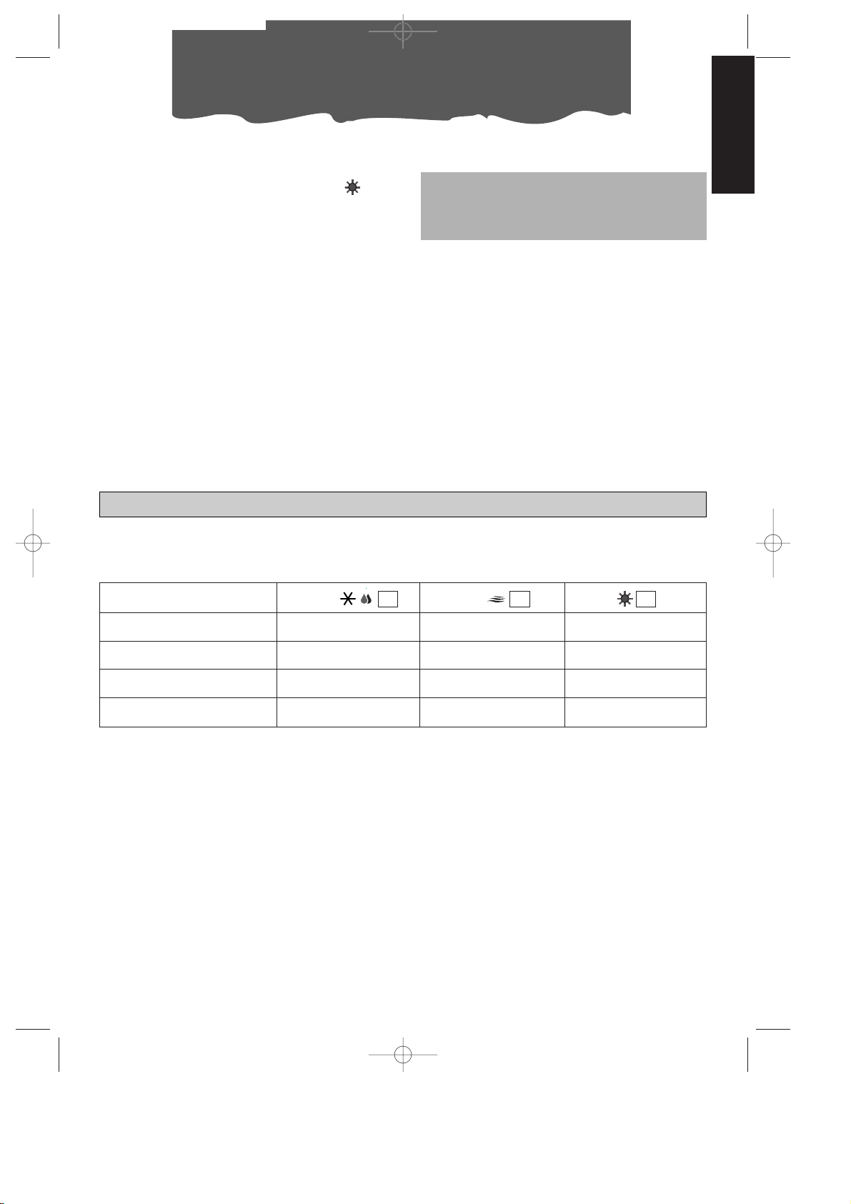
COME RISCALDARE (solo mod. F300)
Ruotate il selettore delle funzioni in senso
antiorario fino a raggiungere il simbolo .
Nota
La temperatura non è espressa in gradi. Vi
suggeriamo pertanto di ruotate la manopola
termostato ambiente sulla posizione di massimo caldo; quando la temperatura ottenuta
nell’ambiente sarà quella di comfort desiderato, potrete ruotare lentamente la manopola del termostato in senso antiorario fino a
quando il termostato interverrà spegnendo il
funzionamento. Così facendo avrete programmato l’apparecchio sull’esatto grado di
comfort che il termostato manterrà automaticamente consentendoVi al tempo stesso un
notevole risparmio energetico. Ogni volta
che il climatizzatore raggiunge la temperatura obiettivo, continuerà ad operare in funzione di sola purificazione.
SPEGNIMENTO DELL’APPARECCHIO
PER DETERMINARE L'ARRESTO COMPLETO
DELL'APPARECCHIO, RIPORTATE IL SELETTORE DI FUNZIONE IN POSIZIONE DI “●” E
SCOLLEGATE LA SPINA.
L’AVVIO DELLE FUNZIONI PUÒ SUBIRE DEI LIEVI RITARDI RISPETTO ALLA ROTAZIONE DEL SELETTORE.
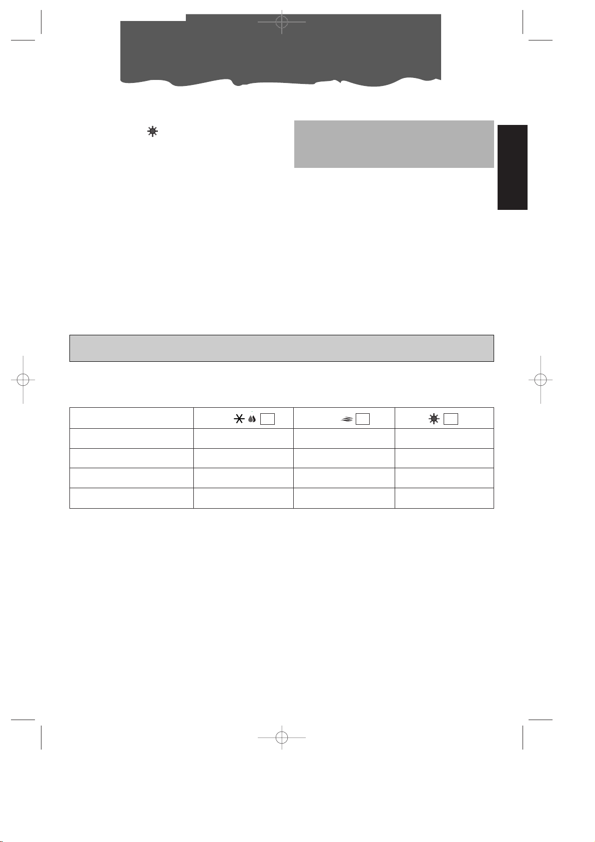
SPIE LUMINOSE
Le spie luminose segnalano il funzionamento della macchina.
FUNZIONE
SPIA /
24
SPIA
25
OFF
--
CONDIZIONAMENTO
accesa* accesa
PURIFICAZIONE
- accesa
-
-
-
RISCALDAMENTO
- accesa
accesa
SPIA
(F300)
26
* Le spie si accenderanno 3 minuti dopo l’accensione della macchina (cioè quando il com-
pressore inizierà a funzionare). Si spegneranno invece quando la temperatura impostata dal
termostato sarà raggiunta.
I 8-08-2001 9:27 Pagina 13
Page 14
14
Ci sono alcune avvertenze da seguire per
ottenere il massimo rendimento dal climatizzatore:
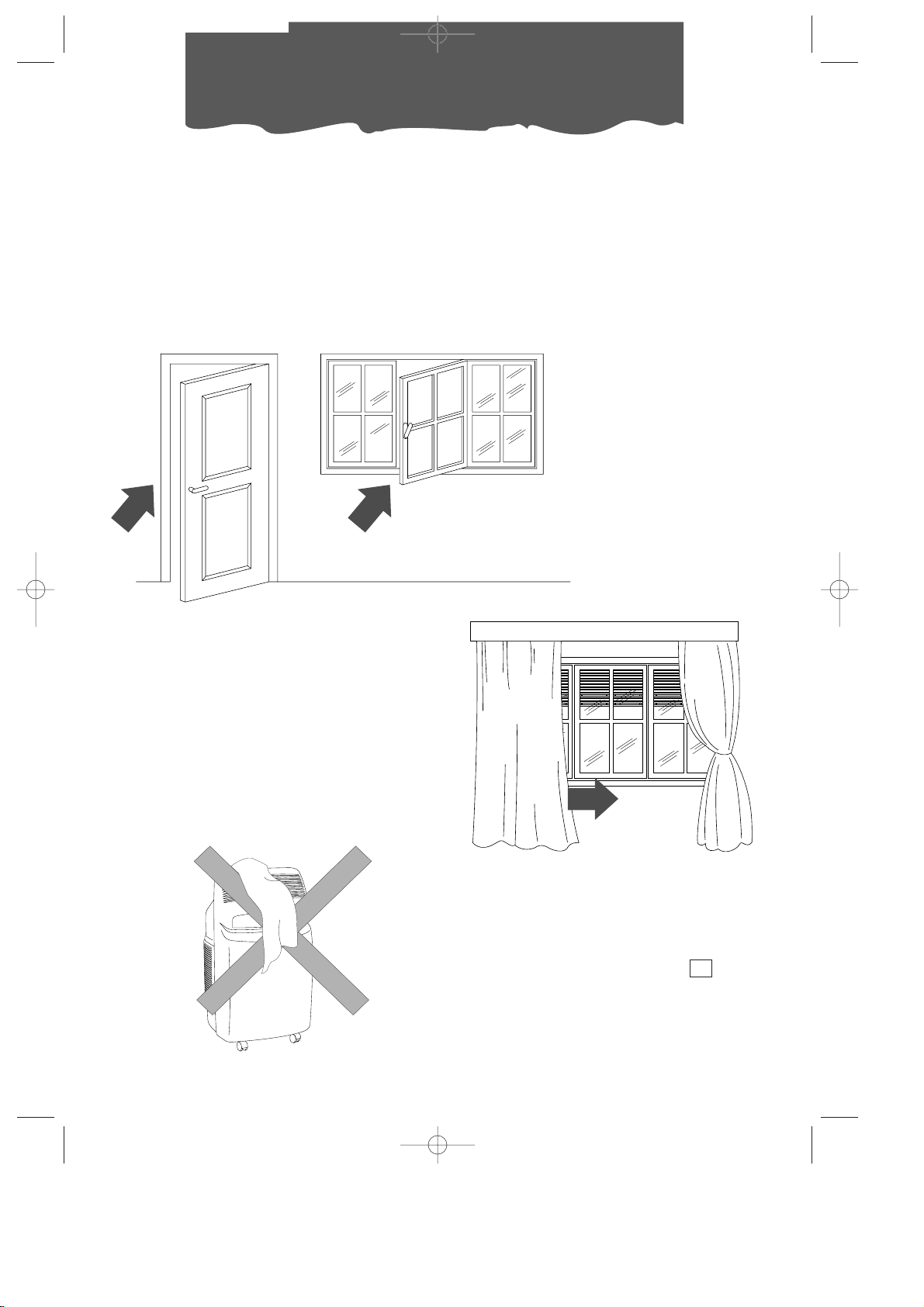
• chiudete i serramenti dell’ambiente da climatizzare. Unica eccezione nel caso di
installazione attraverso un foro nella parete.
In tal caso è consigliabile lasciare uno spiraglio attraverso una porta o finestra, così da
garantire il giusto cambio d’aria.
• Proteggete la stanza dalle esposizioni
dirette del sole, tirando le tende e/o
abbassando parzialmente le persiane in
modo da avere un funzionamento estremamente economico;
• Non appoggiare oggetti sul climatizzatore;
• Non ostacolare l’aspirazione e la mandata d’aria;
• Assicurarsi che nell’ambiente non vi siano
sorgenti di calore.
Consigli
chiudere porte e finestre
abbassare le persiane o tirare le tende
non coprire
• Controllare che il climatizzatore sia posizionato su un pavimento “
in piano”. Inserire
eventualmente i 2 fermaruote sotto le
ruote anteriori.
22
• Non utilizzare l’unità interna in ambienti ad
alto tasso di umidità (es. lavanderia).
• Non utilizzare l’unità interna in ambiente
esterno.
• Solo mod. F300: tenere l’apparecchio ad
una adeguata distanza da superfici combustibili.
I 8-08-2001 9:27 Pagina 14
Page 15
15
ITALIANO
Prima di ogni operazione di pulizia o di manutenzione, spegnete l’apparecchio posizionando il selettore su “
●●” e staccate sem-
pre la spina dalla presa di corrente.
PULIZIA DEL MOBILE ESTERNO
Vi suggeriamo di pulire l’apparecchio con un
panno che sia soltanto inumidito ed asciugare con un panno asciutto. Per motivi di sicurezza non lavate il climatizzatore con acqua.
Precauzioni
Mai usare benzina, alcool o solventi per la pulizia. Mai spruzzare liquido insetticida o simili.
PULIZIA DEI FILTRI ARIA.
Per mantenere inalterata l'efficienza del
vostro climatizzatore. Vi consigliamo di:
1. Pulire il filtro antibatterico ogni settimana
2. Sostituire il filtro FILTRETETMal termine di ogni
stagione, o comunque quando sarà esausto
(seguite le indicazioni poste sull’apparecchio
presso la sede del filtro).
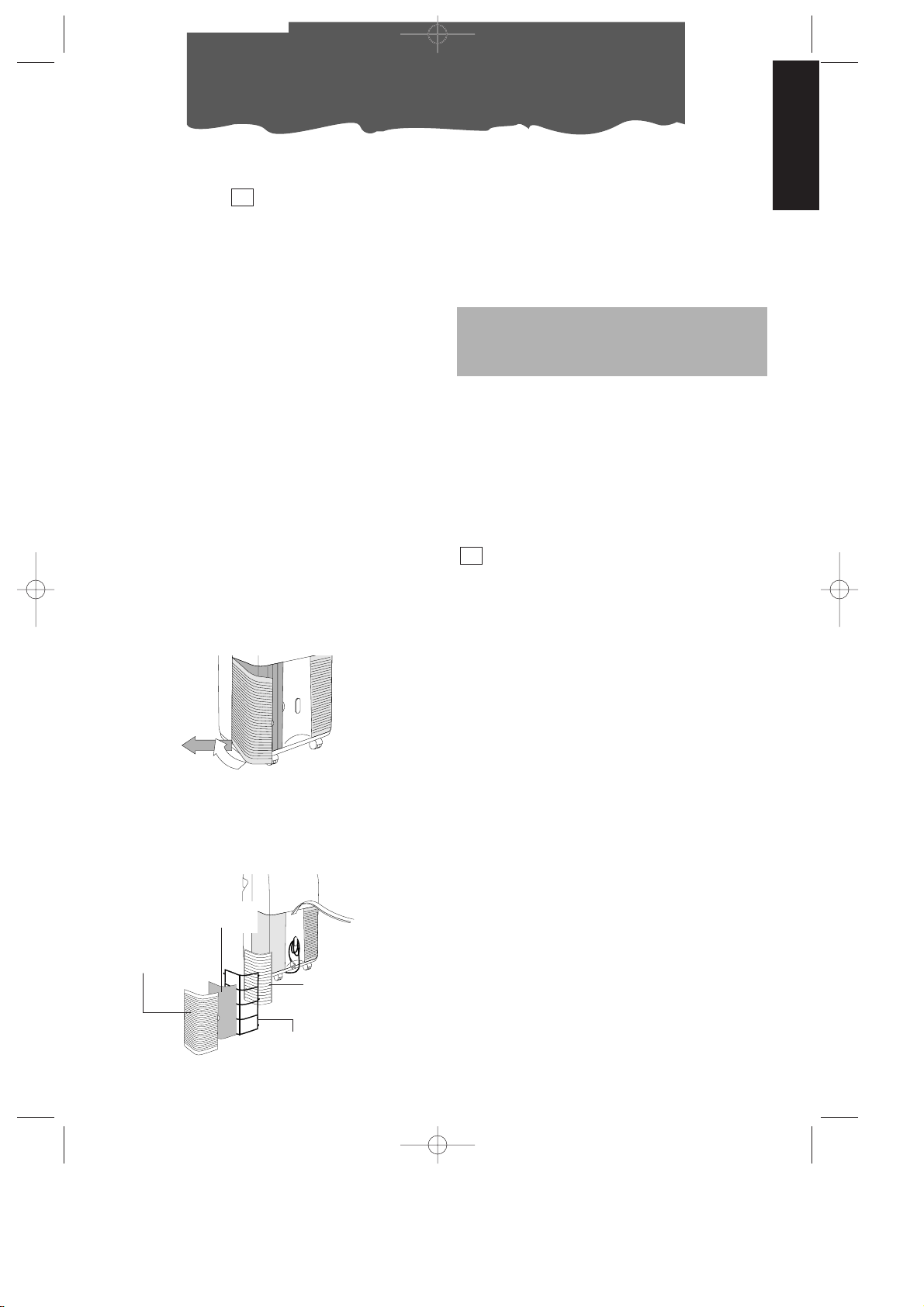
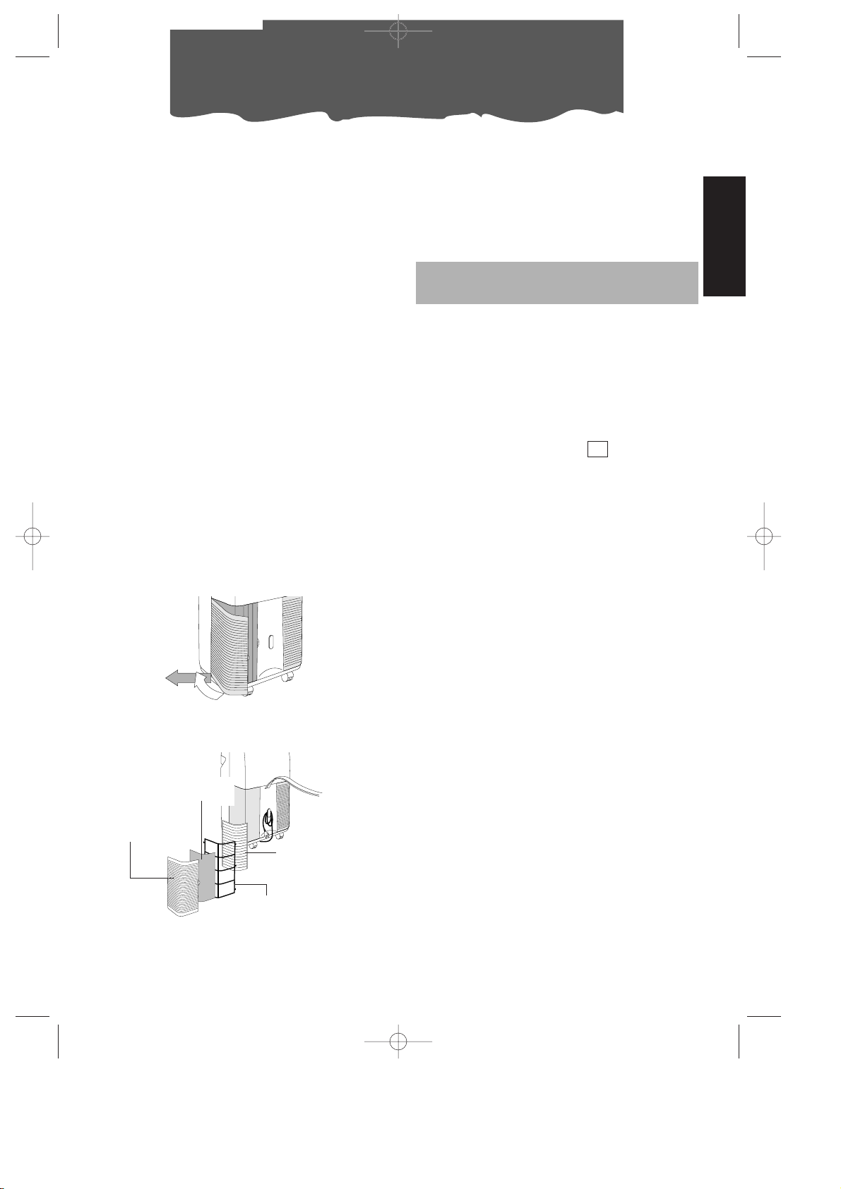
I filtri per la purificazione dell'aria si trovano in
corrispondenza delle due griglie di aspirazione. Le griglie sono a loro volta la sede degli
stessi filtri.
Per la pulizia dei filtri sarà quindi necessario:
1. Rimuovere le griglie di aspirazione, ruotandole verso l'esterno (fig.
F).
23
Per togliere la polvere depositata sul filtro
antibatterico usare un aspirapolvere. Se è
molto sporco immergerlo in acqua tiepida
risciacquando più volte. La temperatura dell’acqua va mantenuta sotto i 40° C.
Dopo averlo lavato, lasciare asciugare il filtro.
Per reinserirlo, ricollocate i filtri nel portafiltro,
quindi riagganciare quest’ultimo alla macchina.
Non cercate di pulire il filtro FILTRETETM,
poiché questo potrebbe diminuirne la
capacità di filtraggio.
VERIFICHE DI INIZIO STAGIONE
Verificate che il cavo di alimentazione e la
presa siano perfettamente integri e assicuratevi che l’impianto di messa a terra sia efficiente. Osservate scrupolosamente le norme
di installazione.
OPERAZIONI DI FINE STAGIONE
Fate uscire l’acqua della bacinella di raccolta togliendo il tappo del tubo di drenaggio
.
Pulite i filtri antibatterici e fateli asciugare
bene prima di reinserirli.
Coprite l’apparecchio con un sacchetto di
plastica per evitare che si impolveri.
11
Pulizia
2. Rimuovere il 1° filtro FILTRETETM(di colore
bianco)
3. Rimuovere il portafiltro sede del filtro antibatterico sganciandolo dalla griglia esterna.
1
2
fig. F
griglia di
aspirazione
filtro
antibatterico
Coprifiltro
Filtro filtrete
TM
(se previsto)
fig. G
I 8-08-2001 9:27 Pagina 15
Page 16

16
Se qualcosa non funziona…
PROBLEMI CAUSE RIMEDI
Il climatizzatore non
funziona
• manca la corrente
• la spina non è inserita
• il selettore di funzione è in posizione “O”
• la levetta del timer è su STOP
• la levetta del timer è sulla posizione “funzionamento con timer” e il timer non è
impostato correttamente
• attendere
• inserire la spina
• spostare il selettore nella posizione desiderata
• portare la levetta del timer sulla
posizione manuale
• reimpostare il timer seguendo le
istruzioni di pag. 11.
Il climatizzatore funziona solo per poco
tempo
• è intervenuto il termostato
• ci sono degli ostacoli sull’aspirazione della
unità esterna
• il ventilatore è bloccato
• ruotare la manopola termostato in senso contrario
• togliere gli eventuali ostacoli
• chiamare il Centro Assistenza
Il climatizzatore funziona ma non rinfresca la stanza
• finestre aperte
• nella stanza sta funzionando qualche fonte
di calore (bruciatore, lampada etc.) oppure
vi sono molte persone
• termostato regolato troppo alto
• filtri aria intasati
• il climatizzatore ha una potenzialità non adeguata alle condizioni o alle dimensioni dell’ambiente
• chiudere la finestra
• eliminare la fonte di calore
• abbassare il termostato
• pulire/sostituire i filtri
La spia bacinella
piena è accesa
• l’acqua di condensa non viene scaricata
verso l’esterno
• scaricare l’acqua tramite il
tubetto di scarico
Il climatizzatore non
riscalda a sufficienza (solo mod. F300)
• filtro dell’aria intasati
• la temperatura impostata in modo errato
• le griglie di ingresso sono ostruite
• il locale è troppo grande
• pulire i filtri o sostituirli
• reimpostare la temperatura
• eliminare l’ostacolo
I 8-08-2001 9:27 Pagina 16
Page 17

17
ITALIANO
Garanzia/caratteristiche tecniche
GARANZIA
Troverete allegate all’apparecchio l’elenco dei
Centri Assistenza e la garanzia. Ricordatevi che la
garanzia ha validità solo se accompagnata da un
documento fiscale che comprovi l’acquisto oppure convalidata dal negoziante.
ASSISTENZA TECNICA
Conservate l’elenco dei Centri Assistenza Tecnica
ed individuate il Centro più vicino a voi.
CONDIZIONI LIMITE
DI FUNZIONAMENTO
Temperatura nella stanza 21 ÷ 32°C
Temperatura esterna 21 ÷ 43°C
CARATTERISTICHE TECNICHE
Tensione di
alimentazione vedere targa caratteristiche
Potenza max. assorbita
in condizionamento “
Potenza frigorifera* “
Numero di velocità ventilatore 2
Portata aria max. 460 m3/h
Dimensioni unità interna:
• larghezza 452 mm
• altezza 800 mm
• profondità 415 mm
• peso 35 kg
Dimensioni unità esterna (mod. F400):
• larghezza 570 mm
• altezza 475 mm
• profondità 260 mm
• peso 18 kg
Dimensioni unità esterna (mod. F250/300):
• larghezza 465 mm
• altezza 480 mm
• profondità 240 mm
• peso 12 kg
* Condizioni standard:
Temperatura interna 27°C
47% umidità relativa
Temperatura esterna 35°C
41% umidità relativa
Questo apparecchio contiene sostanze che liberate nell’atmosfera danneggiano lo strato di
ozono perciò si raccomanda di non perforare il circuito frigorifero della macchina. Alla fine della
sua vita utile, consegnate il climatizzatore presso gli appositi centri di raccolta.
I 8-08-2001 9:27 Pagina 17
Page 18

18
During the summer, optimum comfort is achieved with a temperature of between 24 and 27˚C
and about 50% relative humidity.
An air conditioner removes moisture and heat from the room where it is located. One advantage
of portable air conditioning units over fitted models is that they can be moved from one room to
another in the home or even transferred between different buildings.
The hot air in your room is passed through a
coil cooled by refrigerant gas, losing
excess heat and moisture before
being discharged again into the
room.
In single unit models (Pinguino),
a small part of this air is used to
cool the refrigerant gas before, hot and moist, being
discharged outside.
In suitcase models (SuperPinguino), the circuit is
cooled using the air outside.
Each Pinguino and SuperPinguino can also be used
as a fan only.
For more details, contact or
visit our Internet site
www.delonghi.it
What is Pinguino Pinguino and SuperPinguino
I 8-08-2001 9:28 Pagina 18
Page 19
19
ENGLISH
Important Safe-guards
• This appliance has been manufactured
to cool and de-humidify domestic environments and should not be used for
other purposes.
• It is dangerous to alter or modify the
unit's characteristics in any way.
• The appliance must be installed in
conformity with the relevant national
legislation.
• Should repairs be necessary, contact
the nearest authorised Repair Service
Centre. Unauthorised servicing can be
dangerous.
• This appliance is to be used by adults
only; keep children away from it.
• Always ground the appliance. Have the
electrical system checked by a qualified electrician.
• Avoid using extension leads with the
unit.
• Before cleaning or maintenance operations, always unplug the unit from the
socket.
• Do not pull on or place strain on the
power cable when moving the appliance.
• The appliance should not be installed
where the atmosphere may contain
combustible gases, oil or sulphur, or near
heat sources.
• After turning off the conditioner, always
wait at least three minutes before turning it on again.
• Do not rest hot or heavy objects onto
the appliance.
• Clean the anti-bacterial filters at least
once a week.
• Avoid using heaters near the unit.
• If it is not possible to transport the
appliance in an upright position, then
either lay it on its side.
• Before transporting the unit drain the
condensation collecting-tray and tank.
After transportation, wait at least 1 hour
before switching on the unit.
• The packaging materials can be recycled. You are therefore recommended
to place them in the special containers
for differentiated waste collection.
I 8-08-2001 9:30 Pagina 19
Page 20

20
USING THE RAPID COUPLINGS
(models F400 and F300 only)
As an alternative to the methods described
above, the sheath connecting the external
and internal units can be passed through a 6
cm diameter hole in a wall communicating
with the outside.
Setting up
NB: Leave at least 30 cm between the wall
and the appliance.
b) Through a small crack (5.5 cm x 2.5 cm) in
the bottom of a door or the frame of a
window, using the sheath frame provided.
20
PREPARING THE INTERNAL UNIT
Install the appliance inside the room to be air
conditioned, usually near a window or a perimeter wall. The internal unit must be located
on the level. Also use the wheel blocks
supplied. The intake zone (intake grill and
emission zone (outlet grill ) of the internal
unit should be kept clear of obstacles.
2
8
22
cm 30
cm 30
cm 30
POSITIONING THE CONNECTING SHEATH
The sheath connecting the external and
internal units can be passed:
a) Through the crack of a window or door left
ajar. Use the suckers to prevent it from
opening further.
21
4
SHEATH CLIP
ELECTRICAL
CONNECTION
BLOCK GUARD
“U”-STAY
1) Unplug the appliance from the main.
2) Remove the handle by undoing the two
metric screws then remove the front panel.
3) Remove the “U”-stay by undoing the two
metric screws.
4) Remove the sheath clip by undoing the
two metric screws.
5) Use a number 24 spanner to undo the
rotating union on the coupling. At the
same time, use a number 21 spanner to
hold the end of the flexible pipe steady.
Repeat for the second union using a number 24 and a number 19 spanner.
6) Disconnect the condensate pipe from the
pipe fitting.
7) Undo the two self-tapping screws holding
the guard and remove the electrical connection block.
Avoid tight curves in the connection sheath
Rapid couplings in the model F400
In this model, the connections of the external
unit must be disconnected as follows:
I 8-08-2001 9:30 Pagina 20
Page 21
21
ENGLISH
Setting up
Rapid couplings in model F300
In this model, the connections of the internal
unit must be disconnected as follows:
1) Unplug the appliance from the main.
2) Remove the filters on the side.
3) Remove the rear door in the back panel
by undoing the two screws.
4) Remove the metal “U”-stays fixing the
pipes to the appliance (2).
5) Use a number 24 spanner to undue the
rotating union on the coupling. At the
same time, use a number 21 spanner to
hold the end of the flexible pipe. Repeat
for the second union using a number 24
and a number 19 spanner
6) Disconnect the condensate pipe from the
pipe fitting.
7) Remove the electrical connection block.
Avoid tight curves in the connection
sheath
Reconnecting the sheath in models F400 and F300
To reconnect the ends of the connecting
sheath to the internal unit, repeat operations
1, 2, 3, 4, 5, 6 and 7 in reverse order, observing
the following precautions:
• Before passing the sheath through the
hole in the wall, protect the threaded
ends of the rapid couplings with insulating
tape or similar.
• Fit the top two refrigerant couplings to the
bottom two and hand tighten them for
several turns. Check they fit well before
tightening with the spanners used previously
• After connecting the two refrigerant couplings, fix the stays.
• Check the seal of the refrigerant connections by covering the joins with a little
soapy water. No soap bubbles should
form.
Attention
We recommend that disconnection and connection of the rapid couplings be carried out
by qualified personnel.
I 8-08-2001 9:30 Pagina 21
Page 22

22
Setting up
PREPARING THE EXTERNAL UNIT
The external unit can be placed on a terrace
or balcony. In this case, the brackets should
not be used.
The external unit can also be hung on a wall
using the brackets . Proceed as follows:
1)Fix the bracket
to the wall, taking care
to position it as indicated
in the figure. To make
the holes, use the jig on
the cover of the polystyrene packaging
2) Screw the support
blocks to the external unit using the
M4mm screws supplied (taking care to
position them with the
hole for the screw on the top).
3) Hook the external unit
to the brackets, fixing it
with the M6mm screw
.
17
17
13
12
12
Alternatively, for temporary installation, the
external unit can be suspended as shown in
the figure. In this case, use the belts supplied hooked to the eyes ; Before inserting the eyes, remove the rubber bungs.
The external unit can be installed above or at
the same level as the internal unit, providing
the difference in level is not greater than 1.5 m.
The air intake and outlet of the external unit
should be kept clear of obstacles.
Leave at least 6 cm between the wall and
the appliance.
The drops of condensation formed during the
air conditioning function (summer usage) is in
part drained by evaporation by the external
unit. The residual condensation exits the
appliance through the hole at the base of
the external unit. It is possible to utilise the
condensation
drainage pipefitting in
order to make
the condensation flow through a common
rubber tube
(not included).
The drainage
pipe-fitting must
be assembled onto the base of external unit
(see illustration).
The external unit should be protected from
rain, snow, drips from the roof and the sun.
18
15
14
1
2
Wheel
Coupling
Seal
I 8-08-2001 9:30 Pagina 22
Page 23
23
ENGLISH
Turning on and selecting the functions
CONNECTING TO THE ELECTRICAL MAIN
AND TURNING THE APPLIANCE ON.
1. Before plugging the appliance into the
electrical main, check that:
• mains voltage conforms to the value indicated on the rating plate on the back of
the appliance;
• the socket and power line are adequate
for the required load;
• the socket is the right type for the plug,
otherwise have the socket replaced;
• the socket is connected to an efficient
earth installation.
Failure to observe this
accident prevention rule absolves the
manufacturer of all liability.
12
6
9
1
0
STOP
MANUAL
TIMER - SETTING THE TIME
As with all clocks, the programmer/timer must
be set to the right time. If it is 16.00, rotate the
pointers clockwise (follow the direction of the
arrow) until you reach 16.00 p.m..
NB: never rotate the face in the opposite
direction!
TIMER - PROGRAMMING
1) Set the times when the unit will function by
pushing the teeth in the required interval
towards the outside (each tooth represents 15 minutes).
2) Check that the timer indicates the exact
time (see setting the time).
3) Choose the required function according
to the instructions on the following page.
The timer is an electric clock and only
works while the unit is connected to the
mains. When it is unplugged or there is no
electricity, the timer stops (the clock is
“slow”) and must be put right.
9
8
12
7
4
Period of operation
Example:
from 7 to 9
In this mode, the unit will repeat the set programme every day.
N.B.: It is not necessary to modify the programme to exclude “timer” operation. Just
turn the switch to
1 (manual).
2. Before setting the required function, check
that the switch on the timer is in position
1 (manual).
If you wish to use the timer, position the switch
in the intermediate position .
7
Replacement of the power cable must be
carried out by qualified personnel.
I 8-08-2001 9:30 Pagina 23
Page 24

AS AIR CONDITIONER
With the unit turned off, the function selector
is in the “O” position. To turn the unit on in
air conditioning mode, proceed as follows:
1. Rotate the function selector knob clockwise:
• Place the large crystal symbol in line
with the reference mark to operate the
unit in air conditioning mode at maximum
fan speed.
• Place the small crystal symbol in line
with the reference mark to operate the
unit in air conditioning mode at minimum
fan speed.
2. Now set the required temperature by rota-
ting the room thermostat knob.
Note
The temperature is not expressed in degrees.
We therefore recommend rotating the room
thermostat knob to the maximum cool position. When room temperature has reached
the required level, rotate the thermostat knob
slowly clockwise until the thermostat is activated, turning the unit off. This programs the unit
to the precise level of comfort required which
will then be automatically maintained by the
thermostat with considerable energy savings.
When regulating the thermostat, the air conditioning function is temporarily interrupted
and the unit continues to operate in fan only
mode.
23
24
Selecting functions
THIS UNIT EMPLOYS AN EXCLUSIVE CONDENSATION RECYCLING SYSTEM TO DISPOSE OF EXCESS MOISTURE.
IN NORMAL CONDITIONS, CONDENSATION IS DISPOSED OF AUTOMATICALLY.
WHEN THE HUMIDITY IS PARTICULARLY
HIGH, AN EXCESS OF CONDENSATION
MAY BUILT UP IN THE TANK. WHEN THIS
HAPPENS, THE INDICATOR LIGHT .
COMES ON INDICATING THAT THE TANK
SHOULD BE EMPTIED.
28
AIR PURIFICATION WITH FAN
Your air conditioning unit has two special high
efficiency electrostatic 3M FILTRETE™ filters.
These filters, active in all modes, filter out
extremely fine particles (down to 0.3 thousands of a millimetre).
If you want to purify the air by ventilating the
room only, rotate the function selector
anticlockwise.
• Place the large symbol in line with the
reference mark to operate the unit in air purification mode at maximum fan speed.
• Place the small symbol in line with the
reference mark to operate the unit in air purification mode at minimum fan speed.
23
I 8-08-2001 9:30 Pagina 24
Page 25
25
ENGLISH
Functions/Warning lights
HEATING (mod. F300)
Rotate the function selector knob counter
clockwise to the symbol:
Note
The temperature is not expressed in degrees.
We therefore recommend rotating the room
thermostat knob to the maximum heat position. When the temperature in the room reaches the comfort level desired, the thermostat knob may be turned SLOWLY in a counter
clockwise direction until the thermostat intervenes, turning off the operation. This programs the unit to the precise level of comfort
required which will then be automatically
maintained by the thermostat with considerable energy savings. When regulating the
thermostat, the air conditioning function is
temporarily interrupted and the unit continues to operate in fan only mode.
TURN THE APPLIANCE OFF
TO TURN THE UNIT OFF COMPLETELY, SET
THE FUNCTION SELECTOR TO THE “O” POSITION AND UNPLUG FROM THE MAINS
THE START OF THE FUNCTIONS MAY UNDERGO SLIGHT DELAYS WITH RESPECT TO THE ROTATION OF
THE SELECTOR.
THE LEDS
Led displays come on depending on the selected function or as warning of possible anomalies.
FUNCTION
LED /
24
LED
25
OFF
--
AIR-CONDITIONING
on* on
PURIFYING
- on
-
-
-
HEATING
- on
on
LED
(F300)
26
* The leds will light up 3 minutes after the machine is turned on (that is, when the compressor
starts to work). They will turn off when the temperature set by the thermostat is reached.
I 8-08-2001 9:30 Pagina 25
Page 26

26
Follow these recommendations to achieve
maximum efficiency from your air conditioning unit:
• Close the doors and windows in the room
where the unit is functioning. The only
exception is in the case of installation through a hole in the wall. In this case, you are
recommended to allow a small amount of
air to enter through a door or window to
guarantee an adequate exchange of air.
• Protect the room from direct exposure to
the sun’s rays by drawing the curtains
and/or partially lowering the blinds so as
to maximise energy savings.
• Do not rest objects on the air conditioning
unit.
• Do not obstruct the air intake or outlet.
• Make sure there are no heat sources in the
room.
Recommendations
close doors and windows
lower the blinds or draw the curtains
do not cover
• Make sure the unit is located on a level
floor. If necessary, place the two blocking
devices under the front wheels.
22
• Do not install the heater in humid environments.
• Do not use the appliance outdoors.
•
Mod. F300: Keep the appliance a safe
distance from combustible surfaces
I 8-08-2001 9:30 Pagina 26
Page 27
27
ENGLISH
Before cleaning or maintenance, always turn the
unit off by placing the selector in the “O” position
and unplug from the mains.
CLEANING THE EXTERNAL UNIT
We recommend cleaning the unit with a slightly damp cloth then drying with a dry cloth.
For safety reasons, do not wash the air conditioner with water.
Precautions
Never clean with benzene, alcohol or solvents. Never spray liquid insecticide or similar.
CLEANING THE AIR FILTERS.
To maintain the air conditioning unit at peak
efficiency, you are recommended to:
1. Clean the anti-bacteria filter weekly.
2. Replace the FILTRETE™ filter at the end of
each season or when spent (follow the
instructions on the unit near the filter).
The air purification filters are located behind the
two intake grilles. The grilles in fact house the filters themselves.
To clean the filters:
1.Remove the intake grilles by rotating them
outwards.
3. To remove dust deposited on the anti-bacteria filter, use a vacuum cleaner. If very dirty,
rinse repeatedly in warm water at a temperature of not more than 40°C.
After washing, dry the filter. To replace, put
the filters back into the filter holder, then hook
the latter to the unit.
Do not clean the FILTRETE™ filter as this
would reduce its filtering capacity.
BEGIN OF SEASON CHECKS
Check that the power cable and socket are
undamaged and that the earth installation is
efficient.
Meticulously observe the installation
norms.
END OF SEASON OPERATIONS
Empty the residual water by removing the
bung in the drainage tube .
Take out the condensation tank located in
the rear of the unit and empty it. After replacing the bung, put the condensation tank
back.
Clean the anti-bacteria filters and dry well
before replacing.
Protect the unit from dust by covering with a
plastic bag.
18
Cleaning
2. Remove the first FILTRETE™ filter (white).
1
2
fig. F
intake grille
anti-bacteria
filter
filter cover
filtrete™ filter
fig. G
I 8-08-2001 9:30 Pagina 27
Page 28

28
Troubleshooting
PROBLEM CAUSES REMEDY
The unit does not
work
• the power is off
•
the plug is not inserted into the electrical outlet
• the function selector is in the “•” position
• the timer pointer is on STOP
• the timer pin is in the position and it is not
programmed to operate at that moment
• wait
• plug in
• move the selector to the desired
position
• set the timer pointer to the
manual position
• adjust the timer following the
instructions given on page 23.
The unit works for
only a short time
• the thermostat has cut in
• the external unit intake is obstructed
• the fan is blocked
• turn the thermostat counter
clockwise
• remove the obstructions
• contact the Service Centre
The unit works but
does not cool the
room
• windows open
• a heat source is operating in the room (burner, light, etc.) or there are a lot of people
• thermostat adjusted too high
• air filters clogged
• the output of the unit is insufficient for the
conditions or size of the room
• close the open window
• remove the heat source
• reinsert the tube into its place
• clean the filter or replace
The tank full light is
on
• condensate is not being drained externally • remove the water through the
drain tube
The air conditioner
does not heat sufficiently (mod. F300)
• the air filter is dirty
• the temperature setting is incorrect
• the grill openings are blocked
• the room is too big
• clean the filter or replace it
• reset the temperature
• remove the blockage
I 8-08-2001 9:30 Pagina 28
Page 29
29
ENGLISH
Technical specification
TECHNICAL SPECIFICATION
Power supply see rating plate
Max. absorbed power
in air conditioning “
Max. absorbed power
when heating (mod. F300) “
Refrigerating capacity* “
Number of fan speeds 2
Max. air flow 460 m
3
/h
Dimensions of internal unit:
• width 452 mm
• height 800 mm
• depth 415 mm
• weight 35 kg
Dimensions of external unit:
• width 465 mm
• height 480 mm
• depth 240 mm
• weight 12 kg
* Standard conditions:
Room temperature 27°C
47% relative humidity
Outside temperature 35°C
41% relative humidity
This appliance contains substances which, if liberated into the atmosphere, would damage the
ozone layer. Care should therefore be taken not to perforate the refrigerant circuit. At the end of
its working life, delivery the air conditioning unit to a special collection centre.
RECOMMENDED OPERATING
CONDITIONS
Room temperature 21 ÷ 32°C
Outside temperature 21 ÷ 43°C
ELECTRICAL CONNECTION (U.K. ONLY)
A) If your appliance comes fitted with a plug, it will incorporate a 13 Amp fuse. If it does not fit your socket, the plug should
be cut off from the mains lead, and on appropriate plug fitted, as below. warning: Very carefully dispose of the cut off
plug after removing the fuse: do not insert in a 13 Amp socket elsewhere in the house as this could cause a shock hazard.
With alternative plugs not incorporating a fuse, the circuit must be protected by a 15 Amp fuse. If the plug is a mouldedon type, the fuse cover must be re-fitted when changing the fuse using a 13 Amp Asta approved fuse to BS 1362. In the
event of losing the fuse cover, the plug must NOT be used until a replacement fuse cover can be obtained from your nearest electrical dealer. The colour of the correct replacement fuse cover is that as marked on the base of the plug.
B) If your appliance is not fitted with a plug, please follow the instructins provided below:
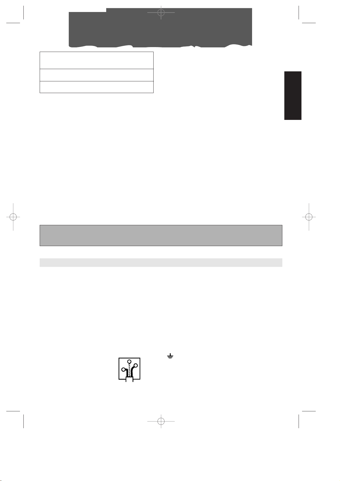
WARNING - THIS APPLIANCE MUST BE EARTHED
IMPORTANT
The wires in the mains lead are coloured in accordance with
the following code:
Green and yellow Earth
Blue Neutral
Brown Live
As the colours of the wires in the mains lead may not correspond with the coloured markings identifying the terminals
in your plug, proceed as follows:
The green and yellow wire must be connected to the terminal in the plug marked with the letter E or the earth symbol
or coloured green or green and yellow.
The blue wire must be connected to the terminal marked with
the letter N or coloured black.
The brown wire must be connected to the terminal marked
with the letter L or coloured red.
N
E
L
I 8-08-2001 9:30 Pagina 29
Page 30
30
Le climatiseur portable Pinguino
Pendant les mois d’été, les conditions de bien-être sont atteintes avec une température com-
prise entre 24°C et 27°C et avec une humidité relative d’environ 50%.
Le climatiseur est un appareil qui enlève l’humidité et la chaleur de la pièce dans laquelle il est
placé. Par rapport aux modèles à installation fixe, les climatiseurs portables présentent l’avantage de pouvoir être non seulement déplacés d’une pièce à l’autre d’une maison mais aussi transportés d’un édifice à un autre.
L’air chaud de votre pièce passe, sous l’effet du gaz réfrigérant, à travers une
batterie de refroidissement où il
cède la chaleur et l’humidité en
excès avant d’être réintroduit
dans la pièce.
Dans les modèles monobloc
(Pinguino), une petite partie
de cet air est utilisée pour
refroidir le gaz réfrigérant;
ensuite, devenue chaude
et humide, elle est évacuée vers l’extérieur.
Dans les modèles avec
unité extérieure (SuperPinguino) le circuit se refroidit
en exploitant l’air extérieur.
Tous les climatiseurs Pinguino
et SuperPinguino peuvent
être également utilisés en
mode seulement ventilation.
Pour tous renseignements complémentaires, vous pouvez contacter
notre site Internet:
www.delonghi.it
I 8-08-2001 9:31 Pagina 30
Page 31

31
FRANÇAIS
Avertissements
• Cet appareil a été conçu pour la climatisation
des locaux domestiques et il ne doit pas être
destiné à d'autres usages.
• Il est dangereux de modifier ou altérer de n'importe quelle façon les caractéristiques de l'appareil.
• L'appareil doit être installé selon les normes en
vigueur dans le pays d'installation.
• Pour les éventuelles réparations, adressez-vous
toujours et exclusivement aux Centres de Service
Après-Vente agréés par la Firme de construction.
Les réparations effectuées par un personnel non
qualifié peuvent être dangereuses.
• Cet appareil doit être exclusivement utilisé par
des adultes: ne pas laisser des enfants jouer
avec le climatiseur.
• Cet appareil doit être relié à une efficace installation de mise à la terre. Faites contrôler l'installation électrique par un électricien qualifié.
• Evitez d'utiliser des rallonges pour le cordon d'alimentation électrique.
• Avant toute opération de nettoyage ou d'entretien, débranchez toujours la fiche de la prise
de courant.
• Ne tirez pas sur le cordon d'alimentation électrique pour déplacer l'appareil.
• N'installez pas l'appareil dans des locaux où l'air
peut contenir du gaz, de l'huile, du soufre ou
tout près de sources de chaleur.
• Attendez toujours 3 minutes au moins avant de
remettre en marche l'appareil après qu'il a été
éteint.
• Ne déposez pas d'objets lourds ou chauds sur
l'appareil.
• Nettoyez les filtres anti-bactéries au moins une
fois par semaine.
• Evitez d'utiliser des appareils de chauffage tout
près du climatiseur.
• En cas de transport, l'appareil doit resté en position verticale ou être déposé sur un côté.
Avant le transport, veillez à vider la cuvette
recueillant l’eau de condensation ainsi que la
bassine. Après un transport, attendez au moins
1 heure avant de mettre l'appareil en marche.
• Les matériaux utilisés pour l'emballage sont
recyclables. Il est conseillé, par conséquent, de
les déposer dans les conteneurs spéciaux pour
le recyclage de ce type de déchets.
I 8-08-2001 9:32 Pagina 31
Page 32

32
UTILISATION DES RACCORDS RAPIDES
(seulement pour les mod. F400 et F300)
En plus des méthodes décrites ci-dessus, vous
pouvez faire passer la gaine qui relie l’unité
externe à l’unité interne à travers un orifice
ayant un diamètre de 6 cm environ, réalisé
dans un mur communicant avec l’extérieur.
Préparation à l’emploi
REMARQUE: L'appareil doit se trouver à une
distance minimale de 30 cm par rapport aux
murs de la pièce.
b) à travers un petit passage (5,5 cm x 2,5
cm) réalisé dans la partie inférieure d’une
porte ou sur le châssis d’une fenêtre, en
utilisant le cadre pour gaine fourni
avec l’appareil.
20
INSTALLATION DE L’UNITE INTERNE
Installez l'appareil à l’intérieur de la pièce à
climatiser. Généralement, près d’une fenêtre
ou de toute façon tout près d’un mur extérieur. L’unité interne doit être placée sur un
plan horizontal, en utilisant également les
cale-roulettes fournis avec l’appareil.
Vérifiez s'il n’y a aucun obstacle dans la zone
d’aspiration (grille d’aspiration ) et dans la
zone d’expulsion (grille de sortie ) de l’unité interne.
2
8
22
cm 30
cm 30
cm 30
POSITIONNEMENT DE LA GAINE DE RACCORDEMENT
Vous pouvez faire passer la gaine qui relie
l’unité externe à l’unité interne:
a) à travers l’entrebâillement d’une fenêtre
ou d’une porte entrouverte; utilisez les
ventouses pour empêcher son ouverture complète.
21
4
BLOC DE
CONNEXION
ELECTRIQUE
CAVALIER
1) Enlevez la fiche de la prise de courant
2) Enlevez la poignée en dévissant les 2 vis
métriques, puis enlevez la façade.
3) Enlevez le cavalier en dévissant les 2 vis
métriques.
4) Retirez le fixe-gaine en dévissant les 2 vis
métriques.
5) A l’aide d’une clé anglaise de 24, dévissez
l’embout tournant du raccord, en tenant
simultanément, au moyen d’une clé de
21, immobile l’extrémité du tuyau flexible.
(Renouvelez l’opération pour le deuxième
embout en utilisant une clé de 24 et une
clé de 19).
6) Détachez le tuyau de l’eau de condensation du porte-caoutchouc.
7) Dévissez les 2 vis autofileteuses de la protection et débranchez le bloc de connexion électrique.
Evitez les courbes trop sèches à la gaine
de raccordement.
Raccords rapides pour mod. F400
Dans ce dernier cas, les raccordements de
l’unité externe devront être déconnectés en
procédant de la manière suivante:
PROTECTION FIXEGAINE
I 8-08-2001 9:32 Pagina 32
Page 33

33
FRANÇAIS
Préparation à l’emploi
5)A l’aide d’une clé anglaise de 24, dévissez
l’embout tournant du raccord, en tenant
simultanément, au moyen d’une clé de
21, immobile l’extrémité du tuyau flexible.
(Renouvelez l’opération pour le deuxième
embout en utilisant une clé de 24 et une
clé de 19).
6) Détachez le tuyau de l’eau de condensation du porte-caoutchouc.
7) Débranchez le bloc de connexion électrique.
Evitez les courbes trop sèches à la gaine
de raccordement.
Reconnexion de la gaine pour les mod. F400
ou F300
Pour connecter à nouveau les extrémités de
la gaine de raccordement, détachée précédemment, renouvelez les opérations 1, 2, 3, 4,
5, 6 et 7 dans l’ordre inverse, en respectant les
précautions suivantes:
• Avant de faire passer la gaine à travers
l’orifice du mur, il est conseillé de protéger
les extrémités filetées des raccords rapides
avec du ruban isolant ou autre matériau
similaire.
• Emboîtez les 2 raccords frigorifiques supérieurs aux 2 raccords inférieurs et vissez-les
manuellement sur plusieurs tours en contrôlant qu’ils sont bien emboîtés. Serrez-les
ensuite à fond à l’aide des clés utilisées
précédemment.
• Après avoir relié les deux raccords frigorifiques, fixez les cavaliers.
• Vérifiez l’étanchéité des raccordements
frigorifiques en mouillant les joints avec un
peu d’eau savonneuse. Assurez-vous qu’il
n’y ait pas de formation de bulles de
savon.
Attention
Il est conseillé de faire effectuer les opérations de démontage et remontage des raccords rapides par un personnel qualifié.
Raccords rapides pour mod. F300
Dans ce dernier cas, les raccordements
devront être déconnectés du meuble de l’unité interne en procédant de la manière suivante:
1) Enlevez la fiche de la prise de courant.
2) Enlevez les filtres situés sur le côté.
3) Enlevez le panneau arrière du dos de l’unité en dévissant les 2 vis.
4) Enlevez les cavaliers en tôle qui fixent les
tuyaux de l'appareil (n°2).
I 8-08-2001 9:32 Pagina 33
Page 34

34
Préparation à l’emploi
POSITIONNEMENT DE L’UNITE EXTERNE
L’unité externe peut être placée sur le sol
d’une terrasse ou d’un balcon. Dans ce cas,
il n’est pas nécessaire d’utiliser les brides.
L’unité externe peut être fixée au mur au
moyen des brides prévues à cet effet.
Dans ce cas, procédez de la manière suivante:
1) fixez la bride au mur
en veillant à la positionner comme illustré à la
figure ci-contre (pour le
perçage des trous, vous
pouvez utiliser le gabarit
présent sur le couvercle
en polystyrène de l’emballage);
2) vissez les blocs de support sur l’unité
externe à l’aide des vis
M4mm fournies
avec l'appareil (en veillant à les positionner
avec le trou pour la vis
sur la partie supérieure);
3) accrochez ensuite l’unité extérieure aux brides en la fixant ensuite
avec la vis M6mm .
17
20
13
12
12
Il est également possible, dans le cas d’installations provisoires, de suspendre l’unité externe comme illustré à la figure ci-dessous. Dans
ce cas, utilisez les courroies fournies qui
doivent être accrochées aux œillets ;
avant d’insérer les œillets, enlevez les bouchons en caoutchouc.
L’unité externe peut être installée au-dessus
ou au même niveau que l’unité interne, à
condition que la dénivellation ne dépasse
pas 1,5 m.
Veillez à ce qu’il n’y ait aucun obstacle tant
sur l’aspiration que sur le refoulement de l’air
de l’unité externe.
Laissez une distance minimale de 6 cm entre
le dos de l’appareil et le mur.
L'eau de condensation qui se forme pendant
le fonctionnement en climatisation (mode
été) est partiellement éliminée par évaporation par l’unité extérieure. La condensation
résiduelle est
évacuée par
l’orifice à la
base de l’unité
extérieure. Il est
possible d’utiliser le raccord
de vidange
pour faire couler l'eau de condensation au
travers d’un
tuyau de caoutchouc ordinaire (non fourni
avec l'appareil). Le raccord de vidange doit
être monté sur la base de l’unité extérieure
(voir figure).
Il est conseillé de protéger l’unité externe
contre la pluie, la neige, les gouttes d’eau
provenant des toits et le soleil.
18
15
14
1
2
Roulette
Raccord
Joint
I 8-08-2001 9:32 Pagina 34
Page 35

35
FRANÇAIS
Mise en marche et sélection des fonctions
BRANCHEMENT AU RESEAU ELECTRIQUE
ET MISE EN MARCHE DE L'APPAREIL
1. Avant de brancher la fiche dans la prise de
courant, vérifiez si:
• la tension du secteur correspond bien à la
tension indiquée sur la plaque signalétique
apposée sur la partie arrière de l'appareil;
• la prise et la ligne d’alimentation électrique sont en mesure de supporter la charge de l’appareil;
• la prise est appropriée à la fiche de l’appareil; en cas d’incompatibilité, faites
remplacer la prise;
• la prise est reliée à une installation de mise
à la terre efficace.
Le fabricant décline
toute responsabilité en cas de nonrespect de cette norme pour la prévention
des accidents.
12
6
9
1
0
STOP
MANUALE
MINUTERIE: MISE À L’HEURE
La minuterie/programmateur, comme toutes
les horloges, doit être mise à l’heure. Par
exemple, s’il est 16 heures, vous devez tourner
les aiguilles dans le sens des aiguilles d'une
montre (en suivant le sens de la flèche) de
manière à régler 16 heures.
N.B.: Ne faites jamais tourner le cadran dans
le sens inverse!
MINUTERIE: PROGRAMMATION
1) Sélectionnez les périodes de fonctionnement en poussant vers l’extérieur toutes les
petites dents comprises dans l’intervalle
souhaité (chaque dent correspond à 15
minutes).
2) Vérifiez que la minuterie indique l’heure
exacte (voir mise à l’heure).
3) Choisissez la fonction souhaitée en suivant
les instructions de la page suivante.
La minuterie est une horloge électrique qui
ne fonctionne que si la fiche est branchée
sur le secteur. Chaque fois que la fiche est
débranchée ou que le courant est coupé,
la minuterie s’arrête (l’horloge retarde) et
une nouvelle mise à l’heure peut s’avérer
nécessaire.
9
8
12
7
4
Période de fonctionnement
Exemple:
de 7 à 9 heures.
Ainsi programmé, l'appareil répétera le programme préétabli tous les jours.
N.B.: Si vous souhaitez exclure le fonctionnement “par minuterie”, il n’est pas nécessaire
de modifier le programme; il suffit d’amener
l'interrupteur sur la position 1 (manuel).
2. Avant de sélectionner la fonction
souhaitée, vérifiez si l'interrupteur situé sur la
minuterie est sur la position 1 (manuel).
Si vous souhaitez utiliser la minuterie, placez
l'interrupteur sur la position intermédiaire .
7
En cas de remplacement du câble d’alimentation, mettez-vouz en contact avec du personnel
spécialisé.
MANUEL
I 8-08-2001 9:32 Pagina 35
Page 36

36
Sélection des fonctions
COMMENT CLIMATISER
Lorsque le climatiseur est éteint, le sélecteur
de fonctions est sur la position “O”. Pour
actionner la fonction de climatisation, procédez de la manière suivante:
1. Tournez le bouton du sélecteur de fonctions dans le sens des aiguilles d'une montre:
• En faisant coïncider le grand symbole du
cristal avec l’index de référence, l’appareil fonctionnera en mode climatisation
à la vitesse maximale de ventilation.
• En faisant coïncider le petit symbole du
cristal avec l’index de référence, l’appareil fonctionnera en mode climatisation
à la vitesse minimale de ventilation.
2. Choisissez à présent la température
souhaitée en tournant le bouton du thermostat d’ambiance.
Remarque
La température n’est pas exprimée en
degrés. Nous vous conseillons, par conséquent, de tourner le bouton du thermostat
d’ambiance sur la position de froid maximal:
quand la température obtenue dans la pièce
sera la température de bien-être souhaitée,
tournez lentement le bouton du thermostat
dans le sens des aiguilles d'une montre
jusqu’au moment où le thermostat interviendra pour couper le fonctionnement de l’appareil. Vous aurez ainsi programmé le climatiseur sur le degré exact de confort souhaité
que le thermostat maintiendra automatiquement, vous permettant d’obtenir en même
temps une économie d’énergie considérable. Lorsqu’il intervient, le thermostat provoque une interruption momentanée de la
fonction de climatisation et le climatiseur
continuera à fonctionner en mode de ventilation seulement.
23
CET APPAREIL UTILISE UN SYSTÈME EXCLUSIF
DE RECYCLAGE DE LA CONDENSATION
POUR ÉLIMINER L’EXCÈS D’HUMIDITÉ.
DANS DES CONDITIONS NORMALES, LA
CONDENSATION EST ÉLIMINÉE AUTOMATIQUEMENT.
DANS DES CONDITIONS D’HUMIDITÉ
ÉLEVÉE, UN EXCÈS D’EAU DE CONDENSATION PEUT S’ACCUMULER DANS LE RÉSERVOIR, SIGNALÉ PAR L’ÉCLAIRAGE DE LA
LAMPE TÉMOIN . DANS CE CAS, IL
SUFFIT DE VIDER LE RÉSERVOIR.
28
COMMENT PURIFIER L’AIR AVEC LA VENTILATION
Votre climatiseur est équipé de deux filtres
électrostatiques spéciaux à très haute efficacité: FILTRETE™ de 3M. Ces filtres sont en
mesure de capter des particules extrêmement petites (jusqu’à 0,3 millièmes de millimètres). Les filtres sont actifs pour toutes les
fonctions sélectionnées
Si vous souhaitez seulement purifier l'air en
aérant la pièce, tournez le sélecteur de fonctions dans le sens inverse à celui des
aiguilles d'une montre.
• En plaçant le grand symbole en face
de l’index de référence, l’appareil fonctionnera comme purificateur d’air à la vitesse
maximale de ventilation.
• En plaçant le petit symbole en face de
l’index de référence, l’appareil fonctionnera
comme purificateur d’air à la vitesse minimale de ventilation.
23
I 8-08-2001 9:32 Pagina 36
Page 37

37
FRANÇAIS
Predisposition des fonctions/Voyants lumineux
Comment chauffer (seulement mod. F300)
Tournez le bouton du sélecteur de fonctions
dans le sens inverse à celui des aiguilles d'une
montre jusqu’au symbol :
La température n’est pas exprimée en
degrés. Nous vous conseillons, par conséquent, de tourner le bouton du thermostat
d’ambiance sur la position de froid maximal:
Quand la température de la pièce correspond à la température de bien-être
souhaitée, vous pourrez tourner lentement le
bouton du thermostat dans le sens inverse à
celui des aiguilles d'une montre jusqu'à ce
que le thermostat intervienne en interrompant le fonctionnement. Vous aurez ainsi programmé le climatiseur sur le degré exact de
confort souhaité que le thermostat maintiendra automatiquement, vous permettant
d’obtenir en même temps une économie
d’énergie considérable. Lorsqu’il intervient, le
thermostat provoque une interruption
momentanée de la fonction de climatisation
et le climatiseur continuera à fonctionner en
mode de ventilation seulement.
ARRETER L’APPAREIL
POUR ARRÊTER COMPLÈTEMENT L’APPAREIL, PLACEZ LE SÉLECTEUR DE FONCTIONS
SUR LA POSITION “O” ET DÉBRANCHEZ LA
FICHE.
LE DÉMARRAGE DES FONCTIONS PEUT SUBIR UN LÉGER RETARD PAR RAPPORT À LA ROTATION DU
SÉLECTEUR.
VOYANTS LUMINEUX
Les voyants lumineux signalent le fonctionnement de l'appareil.
FONCTION
VOYANT /
24
VOYANT
25
ETEINT
--
CLIMATISATION
allumé* allumé
PURIFICATION
- allumé
-
-
-
CHAUFFAGE
- allumé
allumé
VOYANT
(F300)
26
* Les voyants s’allumeront 3 minutes après la mise en marche de l'appareil (c’est-à-dire lorsque
le compresseur commencera à fonctionner). Les voyants s’éteindront lorsque la température
réglée à l’aide du thermostat sera atteinte.
I 8-08-2001 9:32 Pagina 37
Page 38

38
Voici quelques conseils pratiques pour obtenir
un rendement optimal de votre climatiseur:
• fermez toutes les portes et les fenêtres de la
pièce à climatiser, sauf dans le cas d’une
installation à travers un trou percé dans un
mur. Dans ce cas, il est conseillé de laisser
un entrebâillement d’une porte ou d’une
fenêtre afin de garantir un bon renouvellement de l'air dans la pièce.
• Pour garantir un fonctionnement extrêmement économique de votre climatiseur, n’exposez pas la pièce aux rayons
directs du soleil, en fermant les rideaux
et/ou en baissant partiellement les stores.
• Ne déposez pas d’objets sur votre climatiseur.
• N’obstruez pas l’aspiration et le refoulement de l’air.
• Assurez-vous qu’il n’y ait pas de sources
de chaleur dans la pièce.
Conseils pratiques
Fermez les portes et les fenêtres
Baissez les stores ou fermez les rideaux.
Ne couvrez jamais l'appareil.
• Contrôlez que le climatiseur soit positionné
sur un sol “
parfaitement plat”. Insérez
éventuellement les 2 cale-roulettes
sous les roulettes avant.
22
• Ne pas installer l’unité intene dans des
endroits humides.
• Ne pas utiliser l’unité intene à l’extérieur.
•
Mod. F300: Veillez à positionner l'appareil à
une distance appropriée par rapport aux
surfaces combustibles.
I 8-08-2001 9:32 Pagina 38
Page 39

39
FRANÇAIS
Avant d’effectuer toute opération de nettoyage
ou d’entretien, éteignez l'appareil en plaçant le
sélecteur sur “O” et débranchez toujours la fiche
de la prise de courant.
NETTOYAGE DU MEUBLE EXTÉRIEUR
Nous vous conseillons de nettoyer l'appareil
avec un chiffon tout simplement humide et
de l’essuyer avec un chiffon sec. Pour des raisons de sécurité, ne nettoyez jamais le climatiseur avec de l’eau.
Précautions
N’utilisez jamais d’essence, d’alcool ou de
solvant pour le nettoyage. Ne vaporisez
jamais de liquide insecticide ou similaire..
NETTOYAGE DES FILTRES À AIR
Pour maintenir intacte toute l’efficacité de
votre climatiseur, nous vous conseillons de:
1. Nettoyer le filtre anti-bactéries chaque
semaine.
2. Remplacer le filtre FILTRETE™ à la fin de
chaque saison ou en tout cas quand il sera
épuisé (suivre les indications présentes sur
l'appareil près du logement du filtre).
Les filtres pour la purification de l’air se trouvent
en dessous des deux grilles d’aspiration. Les filtres
sont en fait logés dans les grilles mêmes.
Pour nettoyer les filtres il faudra donc:
1.Enlever les grilles d’aspiration, en les tournant vers l’extérieur.
Pour enlever la poussière qui s’est déposée
sur le filtre anti-bactéries, utilisez un aspirateur.
Si le filtre est très sale, plongez-le dans de
l’eau tiède et rincez-le plusieurs fois. La
température de l’eau doit être inférieure à
40°C.
Après l’avoir lavé, laissez-le sécher avant de
le remettre en place.
N’essayez pas de laver le filtre filtrete™ étant
que cela pourrait diminuer sa capacité de filtrage.
CONTRÔLES AU DÉBUT DE LA SAISON
Vérifiez que le cordon d’alimentation et la
prise soient parfaitement intacts et assurezvous que l’installation de la mise à la terre soit
efficace. Respectez scrupuleusement les normes d'installation.
OPERATIONS A LA FIN DE LA SAISON
Videz l’eau contenue dans la bassine de
stockage en enlevant le bouchon du tuyau
de drainage . Enlevez la cuvette recueillant l’eau de condensation située sur la partie
arrière du climatiseur, videz-la et remettez-la
ensuite en place correctement. Nettoyez les
filtres anti-bactéries et laissez-les sécher complètement avant de les remettre en place.
Protégez l’appareil contre la poussière en le
couvrant avec un sac en plastique.
18
Entretien
2.Enlever le premier filtre FILTRETE™ (de couleur
blanche).
3.Enlever le porte-filtre siège du filtre antibactéries en le décrochant de la grille extérieure.
1
2
fig. F
grille d’aspiration
filtre
anti-bactéries
porte-filtre
filtre
filtrete™
fig. G
I 8-08-2001 9:32 Pagina 39
Page 40

40
Si l’appareil ne fonctionne pas normalement…
PROBLEMES CAUSE SOLUTIONS
Le climatiseur ne
fonctionne pas
• absence de courant
• la fiche n’est pas branchée
• le sélecteur de fonctions est sur la position
“O”
• l’interrupteur situé sur la minuterie se trouve
sur la position STOP
• l'interrupteur de la minuterie est sur la position
et est programmé pour ne pas fonction-
ner en ce moment
• attendez
• branchez la fiche
• déplacez le sélecteur sur la position souhaitée
• placer l’interrupteur situé sur la
minuterie sur la position MANUEL
• réglez la minuterie comme souhaité
(voir page 35).
Le climatiseur ne
fonctionne que
pendant peu de
temps
• le thermostat est intervenu
• des obstacles sont présents sur l’aspiration de
l’unité extérieure
• le ventilateur est bloqué
• déplacez le thermostat sur la posi-
tion plus froid
• vérifiez s’il existe des obstacles
empêchant l’évacuation
• faites appel au Service AprèsVente agréé
Le climatiseur fonctionne mais ne
refroidit pas la
pièce
• fenêtres ouvertes
• une source de chaleur (brûleur, lampe, etc.)
est présente dans la pièce ou il y a beaucoup de monde dans la pièce
• le tuyau d’évacuation de l’air est sorti de son logement
• filtres à air encrassés
• la puissance du climatiseur n’est pas appropriée aux conditions et aux dimensions de la
pièce
• fermez la fenêtre
• éliminez la source de chaleur
• diminuez le thermostat
• nettoyez/remplacez les filtres.
La lampe témoin
“cuvette pleine” est
allumée
• l'eau de condensation n’est pas évacuée
vers l’extérieur
• évacuer l'eau par l'intermédiaire du tuyau d’évacuation
Le climatiseur ne
chauffe pas assez
(mod. F300)
• filtres à air encrassés
• température réglée de manière erronée
• les grilles d’entrée de l’air sont obstruées
• la pièce est trop grande
•
nettoyer les filtres ou les remplacer
•
régler correctement la température
• éliminer l’obstacle
I 8-08-2001 9:32 Pagina 40
Page 41

41
FRANÇAIS
Caracteristiques téchniques
CONDITIONS DE FONCTIONNEMENT
CONSEILLÉES
Température dans la pièce: . . . .21÷32°C
Température extérieure: . . . . . . .21÷43°C
CARATTERISTICHE TECNICHE
Tension
d'alimentation voir plaquette signalétique
Puissance max. absorbée
en climatisation “
Puissance max. absorbée
en fonction chauffage (mod. F300) “
Puissance réfrigérante* “
Vitesses de ventilation 2
Volume air traité max 460 m
3
/h
Dimensions unité interne:
• largeur 452 mm
• hauteur 800 mm
• profondeur 415 mm
• poids 35 kg
Dimensions unité externe (mod. F400):
• largeur 570 mm
• hauteur 475 mm
• profondeur 260 mm
• poids 18 kg
Dimensions unité externe (mod. F250/300):
• largeur 465 mm
• hauteur 480 mm
• profondeur 240 mm
• poids 12 kg
* Conditions standards:
Température interne: 27°C
47% Humidité relative
Température externe: 35°C
41% Humidité relative
Cet appareil contient des substances qui, dégagées dans l'atmosphère, nuise à la couche d'ozone; il est, par conséquent, conseillé de ne pas perforer le circuit frigorifique de l'appareil. Lorsque vous décidez de ne plus vous en servir, portez le climatiseur à une société de traitement des
déchets autorisée.
I 8-08-2001 9:32 Pagina 41
Page 42

42
Im Sommer wird das Wohlbefinden bei einer Temperatur zwischen 24 und 27°C und einer relati-
ven Feuchte von etwa 50% erreicht.
Das Klimagerät ist eine Maschine, die dem Raum, in dem sie aufgestellt ist, Feuchtigkeit und
Wärme entzieht. Im Gegensatz zu den festinstallierten Modellen haben die tragbaren Klimageräte den Vorteil, daß sie von einem Raum in einen anderen umgestellt und von einem in ein anderes Gebäude befördert werden können.
Die warme Luft Ihres Raumes durchläuft
eine Batterie, die durch ein Kühlgas
gekühlt wird. Auf diese Weise gibt
sie übermäßige Wärme und Feuchtigkeit ab, bevor sie wieder in
den Raum zurückgeleitet wird.
Bei den einteiligen Modellen
(Pinguino) wird ein geringer
Teil dieser Luft verwendet,
um das Kühlgas zu kühlen,
die dann warm und feucht
geworden, nach außen
abgegeben wird.
Bei den Modellen mit zwei
Einheiten (SuperPinguino)
kühlt sich der Kreis mit Hilfe
der Außenluft.
Alle Pinguino und SuperPinguino können auch allein in
der Betriebsart Belüftung eingesetzt werden.
Für weitere Informationen und
Erläuterungen können Sie an unsere
Internet-Adresse wenden:
www.delonghi.it
Was sind Pinguino und SuperPinguino?
I 8-08-2001 9:33 Pagina 42
Page 43

43
DEUTSCH
• Dieses Gerät wurde ausschließlich als Haushaltsgerät zum Kühlen von Wohnräumen
entwickelt und darf nicht zweckentfremdet
werden.
• Eingriffe oder Änderungen, die die Betriebseigenschaften des Gerätes verändern,
stellen eine Gefahrenquelle dar.
• Das Gerät muß gemäß den inländischen
Vorschriften für den Anlagenbau installiert
werden.
• Eventuelle Reparaturen am Gerät dürfen
ausschließlich durch vom Händler autorisierte Kundendienststellen ausgeführt werden.
Reparaturen, die von Nichtfachleuten vorgenommen werden, können gefährlich
sein.
• Dieses Gerät darf ausschließlich von Erwachsenen bedient werden. Verhindern Sie,
daß Kinder damit spielen.
• Das Gerät darf nur an eine einwandfrei
geerdete Steckdose angeschlossen werden. Lassen Sie im Zweifelsfall Ihre Hausstromversorgungsanlage von einem Elektriker überprüfen.
• Vermeiden Sie möglichst die Verwendung
von Verlängerungskabeln.
• Vor Beginn jeder Reinigungs- oder Wartungsarbeit stets den Netzstecker aus der Steckdose ziehen.
• Ziehen Sie zum Verstellen des Gerätes nicht
dirket am Netzkabel.
• Das Gerät nicht in der Nähe von Wärmequellen aufstellen oder in Räumen, wo die
Luft Gas, Schwefel oder Öl enthalten könnte.
• Warten Sie nach dem Abschalten des
Gerätes stets mindestens 3 Minuten ab,
bevor Sie es erneut einschalten.
• Stellen Sie keine schweren oder heißen
Gegenstände auf das Gerät.
• Reinigen Sie die antibakteriellen Filter mindestens einmal pro Woche.
• Verwenden Sie keine Heizungen in der
Nähe des Klimagerätes.
• Transportieren Sie das Gerät nur in vertikaler
Stellung bzw. auf eine Seite gelegt.
Entleeren Sie vor dem Transport den Kondenswasserbehälter und die Auffangschale. Vor der erneuten Inbetriebsetzung nach
dem Transport, warten Sie mindestens 1
Stunde ab.
• Das Verpackungsmaterial kann recycelt
werden. Entsorgen Sie es daher in den entsprechenden Behältern für getrennte
Abfallsammlung.
Sicherheitshinweise
I 8-08-2001 9:34 Pagina 43
Page 44

44
VERWENDUNG DER SCHNELLANSCHLÜSSE
(nur bei den Modellen F400 und F300)
Außer den vorstehend beschriebenen Aufstellungsarten, kann die ummantelte Anschlußleitung, die das Kühlaggregat mit dem Klimagerät verbindet, auch in einer Maueröffnung mit einem Durchmesser von 6 cm verlegt werden.
Vorbereitung für den Betrieb
Hinweis: Das Gerät muß in einer Entfernung
von mindestens 30 cm zu den Wänden aufgestellt werden.
AUFSTELLUNG DES KLIMAGERÄTES
Das Gerät in dem zu kühlenden Raum aufstellen. Das Gerät sollte möglichst unter einem
Fenster bzw. an einer Außenwand aufgestellt
werden. Darauf achten, daß das Klimagerät
auf einem völlig ebenen Boden positioniert
wird, bedienen Sie sich im Bedarfsfall der mitgelieferten Rollensicherungen Achten
Sie insbesondere darauf, daß der Lufteingang
(Ansauggitter ) und der Luftausgang (Ausströmgitter ) frei von Hindernissen sind.
2
8
22
cm 30
cm 30
cm 30
VERLEGEN DER UMMANTELTEN ANSCHLUßLEITUNG
Die ummantelte Anschlußleitung die das Kühlaggregat mit dem Klimagerät verbindet, kann folgendermaßen verlegt werden:
a) Durch einen Fensterschlitz bzw. eine angelehn-
te Türe. Verwenden Sie die Saugköpfe
,
um
ein vollständiges Öffnen zu verhindern.
21
4
HALTERUNG DER
UMMANTELTEN LEITUNG
SCHUTZAB-
DECKUNG ELEK-
TRISCHE VERBIN-
DUNGEN
BÜGELBOLZEN
1) Ziehen Sie den Netzstecker aus der Steckdose.
2) Entfernen Sie den Handgriff durch Lösen
der beiden Feinstellschrauben und ziehen
Sie dann die Frontplatte heraus.
3) Entfernen Sie den Bügelbolzen durch
Lösen der beiden Feinstellschrauben.
4) Entfernen Sie die Halterung der ummantelten Leitung durch Lösen der beiden
Feinstellschrauben.
5) Mit Hilfe eines 24iger Schraubenschlüssels
lösen Sie den drehbaren Schraubstutzen
des Anschlußstückes und halten gleichzeitig das Schlauchende mit einem 21iger
Schraubenschlüssel fest. (Wiederholen Sie
den Arbeitsgang für den zweiten Schraubstutzen und verwenden Sie hierzu einen
24iger und einen 19er Schraubenschlüssel).
6) Ziehen Sie den Kondenswasserabflußschlauch von der Schlauchhalterung.
7) Lösen Sie die beiden Gewindeschrauben
von der Schutzabdeckung und lösen Sie
die elektrischen Verbindungen.
Vermeiden Sie zu starke Krümmungen der
ummantelten Anschlußleitung.
Schnellanschlüsse beim Modell F400
In diesem Fall müssen die Anschlüsse des Kühlaggregates wie folgt abgetrennt werden:
b) Durch eine kleine, am unteren Teil der Türe bzw.
am Fensterrahmen herausgearbeitete Öffnung (5.5 cm x 2.5 cm) und die Montage der
mitgelieferten Anschlußleitungsführung .
20
I 8-08-2001 9:34 Pagina 44
Page 45

45
DEUTSCH
Vorbereitung für den Betrieb
Schnellanschlüsse beim Modell F300
In diesem Fall müssen die Anschlüsse am Klimagerät wie folgt abgetrennt werden:
1) Ziehen Sie den Netzstecker aus der Steckdose
2) Entfernen Sie die seitlich angebrachten Filter.
3) Entfernen Sie durch Lösen der beiden Schrauben die untere Abdeckung auf der
Rückseite.
4) Entfernen Sie die Bügelbolzen aus Blech,
mit denen die Schläuche des Gerätes
befestigt sind (2 Stk.)
5) Mit Hilfe eines 24iger Schraubenschlüssels
lösen Sie den drehbaren Schraubstutzen
des Anschlußstückes und halten gleichzeitig das Schlauchende mit einem 21iger
Schraubenschlüssel fest. (Wiederholen Sie
den Arbeitsgang für den zweiten Schraubstutzen und verwenden Sie hierzu einen
24iger und einen 19er Schraubenschlüssel).
6) Ziehen Sie den Kondenswasserabflußschlauch von der Schlauchhalterung.
7) Lösen Sie die beiden Gewindeschrauben
von der Schutzabdeckung und lösen Sie
die elektrischen Verbindungen.
Vermeiden Sie zu starke Krümmungen der
ummantelten Anschlußleitung.
Wiedermontage der ummantelten Anschlußleitung bei den Modellen F400 und F300
Zur Wiedermontage der ummantelten, vorab
vom Klimagerät abgetrennten Anschlußleitung, gehen Sie gemäß der Punkte 1,2,3,4,5,6
und 7 in umgekehrter Reihenfolge vor und
berücksichtigen nachstehende Vorsichtsmaßnahmen:
• Bevor Sie die Anschlußleitung durch die
Maueröffnung führen, umwickeln Sie die
Schnellanschlüsse mit Isolierband oder
ähnlichem.
• Verschrauben Sie die beiden oberen und
die beiden unteren Kühlmittelleitungen
von Hand, kontrollieren Sie, daß diese richtig gegriffen haben und ziehen Sie diese
dann mit Hilfe der vorab verwendeten
Schraubenschlüssel fest.
• Nachdem Sie die beiden Kühlmittelleitungen verschraubt haben, befestigen Sie
die Bügelbolzen.
• Prüfen Sie die Dichtheit der Kühlmittelleitungen mit Seifenwasser an den Verbindungen. Es dürfen keine Seifenblasen entstehen.
Achtung
Die Abmontage und Wiedermontage der
Schnellanschlüsse sollte möglichst von Fachpersonal vorgenommen werden.
I 8-08-2001 9:34 Pagina 45
Page 46

46
Vorbereitung für den Betrieb
AUFSTELLEN DES KÜHLAGGREGATES
Das Kühlaggregat kann auf einer Terrasse
bzw. einem Balkon aufgestellt werden. In diesem Fall werden keine Befestigungsbügel
benötigt.
Das Kühlaggregat kann mit Hilfe der Befestigungsbügel an einer Außenmauer aufgehängt werden. In diesem Fall verfahren Sie
wie folgt:
1) Befestigen Sie den Bügel
an der Mauer und
achten Sie darauf, daß
er so, wie auf der Abbildung gezeigt, positioniert wird (für die Bohrung bedienen Sie sich der Schablone, die
Sie aus dem Polystyroldeckel der Verpackung ausgeschnitten haben);
2) Schrauben Sie die Hal-
terungen mit den
mitgelieferten Schrauben M 4 mm am
Kühlaggregat fest (beachten Sie dabei,
sie mit dem Loch für die
Schraube an der Oberseite zu positionieren);
3) Hängen Sie jetzt das
Kühlaggregat in die
Bügel und befestigen
Sie es danach mit der
Schraube M 6 mm .
17
17
13
12
12
Alternativ hierzu kann das Kühlaggregat
auch zur zeitweiligen Aufstellung aufgehängt
werden, wie auf der nachstehenden Abbildung gezeigt. Verwenden Sie in diesem Fall
die mitgelieferten Gurte , die in die Ösen
eingehakt werden. Entfernen Sie vor dem
Anbringen der Ösen die Gummistöpsel.
Das Kühlaggregat kann höher oder auf gleicher Ebene mit dem Klimagerät aufgestellt
werden. Der Höhenunterschied darf 1,5 m
jedoch nicht überschreiten.
Die Lufteingangs- und Luftausgangsgitter des
Kühlaggregates müssen frei bleiben.
Zwischen dem Kühlaggregat und der Mauer
muß ein Mindestabstand von 6 cm eingehalten werden.
Das Kondenswasser, das sich während dem
Klimatisierungsbetrieb (Sommerbetrieb) bildet, wird durch Verdampfung zum Teil durch
die externe Einheit entsorgt. Das restliche
Kondenswasser
tritt aus der
Bodenöffnung
der externen
Einheit aus. Es ist
möglich, den
Kondenswasserablaufanschluß
zu verwenden, um das
Kondenswasser
mit einem handelsüblichen Schlauch (wird
nicht mitgeliefert) abzulassen. Der Ablaufanschluß wird am Boden der externen Einheit
angebracht (siehe Abbildung).
Das Kühlaggregat sollte möglichst vor Regen
Schnee, vom Dach heruntertropfendem Wasser und vor Sonne geschützt werden.
18
15
14
1
2
Rolle
Anschlußstück
Dichtung
I 8-08-2001 9:34 Pagina 46
Page 47

47
DEUTSCH
Inbetriebnahme und Wahl der Betriebsarten
ELEKTRISCHER ANSCHLUß UND INBETRIEBNAHME
DES GERÄTES
1. Bevor Sie das Gerät an der Steckdose
anschließen prüfen Sie, ob:
• die Netzspannung mit der auf dem Typen/Leistungsschild auf der Geräterückseite
angegebenen übereinstimmt;
• die Steckdose und die elektrische Versorgungsleistung für die erforderliche Belastung ausgelegt sind;
• die Steckose für den Stecker geeignet ist,
andernfalls die Steckdose auswechseln;
• die Steckdose ordnungsgemäß geerdet
ist.
Der Hersteller übernimmt keine Haftung, wenn diese Unfallschutzvorschrift
nicht eingehalten werden sollte.
12
6
9
1
0
STOP
MANUALE
ZEITSCHALTUHR: EINSTELLEN DER UHRZEIT
Die Programmiervorrichtung/Zeitschaltuhr
muß wie alle Uhren auf die genaue Uhrzeit
eingestellt werden. Nehmen wir an es sei 16
Uhr: Drehen Sie die Zeiger im Uhrzeigersinn
(folgen Sie der Richtung des Pfeils) bis Sie bei
16 Uhr angekommen sind.
Hinweis: Drehen Sie das Ziffernblatt nie in die
entgegengesetzte Richtung.
ZEITSCHALTUHR: PROGRAMMIERUNG
1) Sie stellen die Einschaltzeiten ein, indem
Sie alle Lamellen nach außen drücken, die
sich im gewünschten Zeitraum befinden
(eine Lamelle entspricht15 Minuten).
3) Prüfen Sie, ob die Zeitschaltuhr auf die
genaue Zeit eingestellt ist (siehe Einstellen
der Uhrzeit).
4) Wählen Sie gemäß den Anleitungen auf
der Folgeseite die gewünschte Betriebsart.
Die Zeitschaltuhr ist eine elektrische Uhr, die
nur so lange funktioniert, wie der Stecker
an der Steckdose angeschlossen ist. Wird
der Stecker gezogen oder bei Stromausfall
bleibt die Zeitschaltuhr stehen (die Uhr
“geht nach”) und die Uhrzeit muß gegebenenfalls neu eingestellt werden.
9
8
12
7
4
Einschaltzeit
Beispiel:
von 7 bis 9 Uhr.
Das Gerät wird diese vorprogrammierte
Betriebsart Tag für Tag wiederholen.
Hinweis: Wenn Sie den Betrieb “mit Zeitschaltuhr” ausschließen möchten, müssen Sie kein
anderes Programm eingeben: bringen Sie
einfach den Schalter auf Position
1 (manuell).
2. Bevor Sie die gewünschte Betriebsart einstellen prüfen Sie, ob der Schalter auf der
Zeitschaltuhr ) auf Position 1 steht
(manuell).
Möchten Sie die Zeitschaltuhr verwenden,
stellen Sie den Schalter auf die mittlere Stellung .
7
Das Auswechseln des Netzanschlußkabels
darf nur durch Fachpersonal vorgenommen
werden.
MANUELL
I 8-08-2001 9:34 Pagina 47
Page 48

48
Wahl der Betriebsarten
KÜHLEN
Ist das Klimagerät ausgeschaltet, befindet
sich der Funktionswahlschalter auf Position "O". Um zu kühlen verfahren Sie wie folgt:
1. Drehen Sie den Funktionswahlschalter im
Uhrzeigersinn:
• Wenn Sie das große Eiskristallsymbol
auf das Bezugszeichen positionieren,
arbeitet das Gerät im Kühlbetrieb mit
höchster Gebläsegeschwindigkeit.
• Positionieren Sie das kleine Eiskristallsymbol
auf das Bezugszeichen, arbeitet das
Gerät im Kühlbetrieb mit niedrigster
Gebläsegeschwindigkeit.
2. Wählen Sie jetzt die gewünschte Temperatur, indem Sie den Raumthermostatschalter
drehen.
Nota
Die Temperatur ist nicht in Graden angegeben. Wir empfehlen Ihnen daher, den
Raumthermostatschalter auf die kälteste
Temperatur einzustellen: Hat die Temperatur
den gewünschten Behaglichkeitsgrad erreicht, drehen Sie den Thermostatschalter langsam im Uhrzeigersinn, bis der Thermostat einsetzt und den Betrieb unterbricht. Auf diese
Weise haben Sie das Gerät auf den richtigen
Behaglichkeitsgrad programmiert, der vom
Thermostat automatisch beibehalten wird,
wodurch Sie gleichzeitig eine beachtliche
Energieeinsparung erzielen. Sobald das Klimagerät die gewünschte Temperatur erreicht
hat, arbeitet es nur im Belüftungsbetrieb weiter.
23
IN DIESEM GERÄT BEFINDET SICH EIN EXKLUSIVES KONDENSWASSERRÜCKLAUFSYSTEM ZUR
ENTSORGUNG DER ÜBERSCHÜSSIGEN FEUCHTIGKEIT.
UNTER NORMALEN BEDINGUNGEN WIRD DAS
KONDENSWASSER AUTOMATISCH ENTSORGT.
BEI HOHEN FEUCHTIGKEITSBEDINGUNGEN
KANN ES ZU EINEM ÜBERSCHUß AN KONDENSWASSER IM BEHÄLTER KOMMEN. DIES WIRD
DURCH DAS EINSCHALTEN DER KONTROLLAMPE ANGEZEIGT: IN DIESEM FALL
MUß NUR DER BEHÄLTER ENTLEERT UND
DARAUF GEACHTET WERDEN,
28
LUFTREINIGUNG
Ihr Klimagerät ist mit einem speziellen elektrostatischen, hochwirksamen Filter ausgestattet. FILTRETE™ ist in der Lage, kleinste Partikel
aufzufangen (bis zu 0,3 Mikron, das entspricht
0,3 Tausendsteln eines Millimeters).
Daher kann das Gerät auch als wirklicher Luftreiniger eingesetzt werden. Drehen Sie den
Betriebswahlschalter im Uhrzeigersinn.
• Wird das große symbol punkt gedreht,
arbeitet das Gerät be maximaler Ventilationsgeschwindigkeit im Luftreinigungsbetrieb.
• Wird das kleine symbol auf den Bezugspunkt gedreht, arbeitet das Gerät bei
niedrigster Ventilationsgeschwindigkeit im
Luftreinigungsbetrieb.
23
I 8-08-2001 9:34 Pagina 48
Page 49

49
DEUTSCH
Betriebsarten/Kontrollampen
HEIZEN (nur Mod. F300)
Drehen Sie den Betriebswahlschalter entgegen dem Uhrzeigersinn bis zum Symbol.
Hinweis
Die Temperatur ist nicht in Graden angegeben. Wir empfehlen Ihnen daher, den
Raumthermostatschalter auf die kälteste Temperatur einzustellen: Hat die Temperatur im
Raum den gewünschten Behaglichkeitsgrad
erreicht, drehen Sie den Thermostatschalter
langsam entgegen dem Uhrzeigersinn, bis der
Thermostat einsetzt und den Betrieb unterbricht. Auf diese Weise haben Sie das Gerät auf
den richtigen Behaglichkeitsgrad programmiert, der vom Thermostat automatisch beibehalten wird, wodurch Sie gleichzeitig eine
beachtliche Energieeinsparung erzielen.
Sobald das Klimagerät die gewünschte Temperatur erreicht hat, arbeitet es nur im Belüftungsbetrieb weiter.
AUSSCHALTUNG DES GERÄTES
UM DAS GERÄT GÄNZLICH ABZUSCHALTEN,
BRINGEN SIE DEN FUNKTIONSWAHLSCHALTER
IN POSITION "O" UND ZIEHEN DEN NETZSTECKER.
DER START DER BETRIEBSARTEN KANN SICH NACH DEM DREHEN DES WAHLSCHALTERS GERINGFÜGIG
VERZÖGERN.
KONTROLLAMPEN
Die Kontrollampen zeigen den Betrieb des Gerätes an.
FUNKTION
LED /
24
LED
25
AUS
--
KÜHLUNG
an* an
LUFTREINIGEN
- an
-
-
-
HEIZUNG
- an
an
LED
(F300)
26
* Die Kontrollampen schalten 3 Minuten nach dem Einschalten des Gerätes ein (d.h., wenn der
Kompressor zu arbeiten beginnt). Sie schalten ab, wenn die mit dem Thermostat eingegebene
Temperatur erreicht wurde.
I 8-08-2001 9:34 Pagina 49
Page 50

50
Um die optimale Leistung Ihres Klimagerätes
zu erzielen, hier einige Hinweise:
• Schließen Sie die Fenster und Türen des zu
kühlenden Raumes. Nur im Falle, daß die
Installation durch eine Wandöffnung
erfolgt ist, eine Türe oder ein Fenster leicht
geöffnet halten, um den richtigen Luftaustausch zu gewährleisten.
• Damit Ihr Gerät energiesparend arbeitet,
den Raum vor direkter Sonnenbestrahlung
schützen, indem Sie die Vorhänge
zuziehen und/oder die Rolläden teilweise
herablassen.
• Legen Sie keine Gegenstände auf das Klimagerät.
• Lassen Sie den Lufteingang und den Luftausgang am Gerät frei.
• Vergewissern Sie sich, daß sich keine Wärmequellen im Raum befinden.
Hinweise
Türen und Fenster schließen
Fensterläden schließen oder Gardinen
bzw. Vorhänge zuziehen
non coprire
• Kontrollieren Sie, daß das Klimagerät eben
steht. Befestigen Sie hierzu gegebenenfalls die beiden Rollenfeststeller unter
den vorderen Rollen.
22
• Das Gerät nicht in feuchten Räumen aufstellen.
• Das Gerät nicht Witterungseinflüssen
(Regen, Sonne, Frost usw.) aussetzen.
•
Mod. F300: das Gerät in einem angemessenen Abstand zu entflammbaren Flächen aufstellen.
I 8-08-2001 9:34 Pagina 50
Page 51

51
DEUTSCH
Bevor Sie mit Reinigungs- bzw. Wartungsarbeiten beginnen, schalten Sie das Gerät aus:
Stellen Sie den Wahlschalter auf Position "O"
und ziehen Sie dann stets den Netzstecker
aus der Steckdose.
REINIGUNG DES GERÄTEGEHÄUSES
Wir empfehlen Ihnen, das Gerät mit einem
angefeuchteten Tuch zu reinigen und danach mit einem trockenen Tuch abzuwischen.
Das Klimagerät aus Sicherheitsgründen nicht
mit Wasser reinigen.
Vorsicht
Verwenden Sie zur Reinigung nie Benzin,
Alkohol oder Lösemittel. Sprühen Sie keine
Insektizide oder ähnliches auf das Gerät.
REINIGUNG DER LUFTFILTER
Um die Leistungsfähigkeit Ihres Klimagerätes
nicht zu beeinträchtigen empfehlen wir:
1. den antibakteriellen Filter einmal wöchentlich zu
reinigen
2. Den Filter FILTRETETMbei Saisonende und
vor dem Wegstellen des Klimagerätes auszuwechseln.
Die Luftreinigungsfilter befinden sich hinter
den beiden Luftansauggittern, die ihrerseits
als Filteraufnahme dienen.
Zur Reinigung der Filter verfahren Sie wie folgt:
3. Entfernen Sie die Filteraufnahme des antibakteriellen Filters, indem Sie ihn aus dem
Außengitter aushaken (siehe Abb. 2).
Um den abgelagerten Staub vom antibakteriellen Filter zu entfernen, verwenden Sie
einen Staubsauger. Ist er stark verschmutzt,
waschen Sie ihn in warmem Wasser und spülen ihn danach mehrmals. Die Wassertemperatur sollte unter 40° liegen.
Den gereinigten Filter vollkommen trocknen
lassen, bevor Sie ihn erneut einsetzen.
Waschen Sie den Filter Filtretetm nicht, da dies
dessen Filterleistung herabsetzen könnte.
KONTROLLEN VOR DER WIEDERINBETRIEBNAHME
Prüfen Sie, ob das Netzkabel und der Netzstecker in einwandfreiem Zustand sind. Beachten Sie, daß die Aufstellungsvorschriften
eingehalten werden.
AUFBEWAHREN DES GERÄTES
Lassen Sie das Wasser aus der Sammelschale
ab, indem Sie den Stüpsel des Abflußschlauchs entfernen. Ziehen Sie die Kondenswasserschale heraus, die sich auf der
Geräterückseite befindet und entleeren Sie
diese. Setzen Sie sie danch wieder ordnungsgemäß ein. Reinigen Sie die Antibakterienfilter und lassen Sie diese vollkommen trocknen,
bevor Sie sie erneut einsetzen.
Decken Sie das Gerät mit einem Plastikschutz
ab, um es vor Staub zu schützen.
18
Reinigung
1. Entfernen Sie die Luftansauggitter, indem
Sie diese nach außen drehen (siehe Abb. F)
2. Entfernen Sie den 1. Filter FILTRETETM(weiß)
1
2
Abb. F
Luftreinigungsfilter
Antibakteriellen
Filter
Filteraufnahme
Filter
Filtrete
tm
fig. G
I 8-08-2001 9:34 Pagina 51
Page 52

52
Im Falle eventueller Betriebsstörungen
STÖRUNG URSACHEN ABHILFEN
Das Klimagerät
funktioniert nicht
• Die Stromzufuhr ist unterbrochen
• Der Stecker ist nicht angeschlossen
• Der Funktionsschalter ist auf Position "O"
• Der Zeiger der Zeitschaltuhr steht auf STOP
• Der Zeiger der Zeitschaltuhr steht auf und
die Zeitschaltuhr ist nicht richtig programmiert
• Abwarten
• Den Stecker einstecken
• Den Wahlschalter auf die
gewünschte Position stellen
• Bringen Sie den Zeiger der Zeitschaltuhr in die manuelle Stellung
• ziehe Seite 47, Programmierung
der Zeitschaltuhr.
Das Klimagerät
funktioniert nur über
einen kurzen Zeitraum
• Der Thermostat hat eingesetzt
• Hindernisse am Ansauggitter des Kühlaggregates
• Das Gebläse ist blockiert
• Thermostat zurückdrehen
• Vorhandene Hindernisse entfernen
•
Den Kundendienst benachrichtigen
Das Klimagerät
funktioniert, kühlt
den Raum aber
nicht
• Fenster offen
• Im Raum befindet sich eine Wärmequelle
(Heizkörper, Lampe usw.) oder es halten sich
zu viele Personen auf
• Temperatur falsch eingegeben
• Luftfilter verstopft
• Raumabmessungen bzw. -bedingungen entsprechen nicht der Geräteleistung
• Fenster schließen
• Wärmequelle beseitigen
• Temperatur neu eingeben
• Filter reinigen/auswechseln
Die Kontrollampe
“full” ist eingeschaltet
• Das Kondenswasser wird nicht nach außen
abgeleitet
• Das Wasser durch den Abflußschlauch ablassen
Das Klimagerät
heizt unzureichend
(Mod. F300)
• Luftfilter verstopft
• Temperatur falsch eingegeben
• Die Einlaßgitter sind abgedeckt
• Der Raum ist zu groß
• Filter reinigen/auswechseln
• Temperatur neu eingeben
• Hindernis entfernen
I 8-08-2001 9:34 Pagina 52
Page 53

53
DEUTSCH
Technische Eigenschaften
OPTIMALE BETRIEBSBEDINGUNGEN
(KÜHLUNG)
Raumtemperatur 21 ÷ 32°C
Außentemperatur 21 ÷ 43°C
TECHNISCHE EIGENSCHAFTEN
Anschlußspannung siehe Typenschild
Max. Leistungsaufnahme
bei Kühlung “
Kühlleistung* “
Ventilatorgeschwindigkeitsstufen 2
Max. Luftumwälzung 460 m
3
/h
Abmessungen:
• Breite 452 mm
• Höhe 800 mm
• Tiefe 415 mm
• Gewicht 35 kg
Abmessungen des Kühlaggregates (Mod. F400):
• Breite 570 mm
• Höhe 475 mm
• Tiefe 260 mm
• Gewicht 18 kg
Abmessungen des Kühlaggregates (Mod. F250/300):
• Breite 465 mm
• Höhe 480 mm
• Tiefe 240 mm
• Gewicht 12 kg
* Standard-Betriebsbedingungen
Raumtemperatur 27°C
47% relative Luftfeuchte
Außentemperatur 35°C
41% relative Luftfeuchte
Dieses Gerät enthält Substanzen, die bei ihrer Abgabe in die Atmosphäre die Ozonschicht schädigen können. Durchbohren Sie daher nicht den Kühlkreis der Maschine. Möchten Sie das Klimagerät endgültig ausrangieren, bringen Sie es in eine entsprechende Entsorgungsstelle.
I 8-08-2001 9:34 Pagina 53
Page 54

54
Tijdens het zomerseizoen wordt het welzijn in een ruimte bereikt bij een temperatuur tussen de 24 en de 27°C
en met een relatieve vochtigheidsgraad rond de 50%.
De airconditioner is een apparaat dat vochtigheid en warmte elimineert uit de ruimte waarin hij zich bevindt.
In vergelijking met modellen die geïnstalleerd worden, hebben de draagbare airconditioners het voordeel
dat ze verplaatst kunnen worden van de ene kamer naar de andere in huis, en dat ze van het ene gebouw
naar het andere vervoerd kunnen worden.
De warme lucht in uw kamer wordt door
een batterij geleid die afgekoeld wordt
door middel van een koelgas. Op
deze manier wordt het té veel aan
warmte en vochtigheid afgegeven
voordat de lucht weer in de ruimte geblazen wordt.
Bij de modellen die uit één element bestaan (Pinguino),
wordt een klein gedeelte van
deze gekoelde lucht gebruikt
voor het afkoelen van het
koelgas en dan, nadat de
lucht warm en vochtig is
geworden, naar buiten afgevoerd.
Bij de modellen met twee elementen (SuperPinguino) wordt
het circuit afgekoeld met
behulp van de buitenlucht.
Elke Pinguino en SuperPinguino
kan ook gebruikt worden met uitsluitend de ventilatie functie aan.
Voor meer informatie en uitleg kunt u zich
wenden tot
internet site : www.delonghi.it
WAT ZIJN PINGUINO EN SUPERPINGUINO
I 8-08-2001 9:35 Pagina 54
Page 55

55
NEDERLAND
WAARSCHUWINGEN
• Dit apparaat is ontworpen als airconditioner
voor huiselijke ruimtes en dient niet voor andere
doeleinden gebruikt te worden.
• Het is gevaarlijk de eigenschappen van het
apparaat te wijzigen of te veranderen op welke
manier dan ook.
• Het apparaat dient geïnstalleerd te worden volgens de nationaal voorgeschreven regels
omtrent de installatie.
• Voor eventuele reparaties, dient men zich altijd
en uitsluitend te wenden tot de Technische Assistentie Centra die geautorizeerd zijn door de
Fabrikant. Reparaties uitgevoerd door niet vakbekwaam personeel kunnen gevaarlijk zijn.
• Dit apparaat dient uitsluitend bedient te worden door volwassenen; men dient absoluut niet
toe te laten dat kinderen ermee spelen.
• Dit apparaat dient aangesloten te worden op
een goed functionerende aardleiding: Laat uw
elektriciteitsnet controleren door een vakman.
• Het gebruik van verlengsnoeren dient vermeden te worden.
• Altijd eerst de stekker uit het stopcontact
trekken, alvorens over te gaan tot schoonmaken of onderhoud.
• Niet aan het electriciteitssnoer trekken om het
apparaat te verplaatsen.
• Het apparaat niet installeren in ruimtes waarbinnen de lucht gas, olie of zwavel kan bevatten
en niet in nabijheid van warmtebronnen.
• Na het afzetten altijd minstens 3 minuten wachten alvorens het apparaat weer aan te zetten.
• Geen zware of warme voorwerpen op het
apparaat zetten.
• Minstens elke week de anti-bacterie filters
schoonmaken.
• Het gebruik van verwarmingsapparaten in
nabijheid van de airconditioner vermijden.
• In geval van transport, dien het apparaat in ver
ticale positie te blijven of rustend op een zijkant.
Alvorens het apparaat te transporteren eerst
het condenswaterbakje en de opvangbak
legen. Na een transport minstens één uur
wachten alvorens het apparaat aan te zetten.
• De materialen die gebruikt worden voor de verpakking kunnen gerecycleerd worden. Wij
raden daarom aan deze materialen in de hiervoor bestemde afvalbakken voor gescheiden
verzameling te werpen.
I 8-08-2001 9:36 Pagina 55
Page 56

56
GEBRUIK VAN DE DIRECTE AANSLUITINGEN
(uitsluitend mod. F400 en F300)
Afgezien van de voorafgaand beschreven
methoden, kan de slang die de buiteneenheid
met de binneneenheid verbindt ook lopen via
een opening met een doorsnede van ongeveer 6 cm aangebracht in een buitenmuur.
Installering voor gebruik
N.B.: De afstand tussen het apparaat en de
muur dient minstens 30 cm te zijn.
b) Een kleine opening (5,5 cm x 2,5 cm) aan-
gebracht in het onderste gedeelte van
een deur of in het raamwerk van een venster, door de bijgeleverde huls voor de
slang te gebruiken.
20
INSTALLATIE VAN DE BINNENEENHEID
Het apparaat in de te klimatiseren ruimte
plaatsen. Normaal gesproken in de buurt van
een venster of in ieder geval dichtbij een buitenmuur. De binneneenheid dient “vlak”
geplaatst te worden, gebruik hiervoor ook de
bijgeleverde wielblokkeringen
.
De binneneenheid dient door niets belemmerd te worden rond de aanzuigzone (luchtaanzuigrooster ) en rond de afgiftezone (luchtuitgangrooster ).
2
8
22
cm 30
cm 30
cm 30
INSTALLATIE VAN DE VERBINDINGSSLANG
De slang die de buiteneenheid met de
binneneenheid verbindt, kan geleid worden via:
a) Een raam of een deur die op een kier
staat; de zuignapjes kunnen gebruikt
worden om te voorkomen dat de ramen
of de deur te ver open gaan.
21
4
SLANGBLOKKERING
BESCHERMING
ELECTRISCHE
AANSLUITING-
SPLAATJE
BEUGELBOUT
1) De stekker uit het stopcontact halen
2) Het handvat verwijderen door de 2 metrische schroeven los te draaien, hierna de
voorkant wegschuiven.
3) De beugelbout verwijderen door de 2
metrische schroeven los te draaien.
4) De slangblokkering verwijderen door de 2
metrische schroeven los te draaien
5) Met behulp van een engelse sleutel n. 24
het draaibare verbindingsstuk van de
aansluiting losdraaien. Tegelijkertijd met
een sleutel n. 21 het uiteinde van de flexibile buis vasthouden. (Deze handeling
herhalen voor het tweede verbindingsstuk
met behulp van een sleutel n. 24 en een
sleutel n. 19).
6) De condens afvoerslang losmaken uit de
bevestiging.
7) De twee schroeven losdraaien van de
bescherming en het electrische aansluitingsplaatje loskoppelen.
Te scherpe bochten in de verbindingsslang
vermijden.
Directe aansluiting bij mod. F400
In dit geval dienen de verbindingen van de
buiteneenheid losgekoppeld worden door
als volgt te werk te gaan:
I 8-08-2001 9:36 Pagina 56
Page 57

57
NEDERLAND
Installering voor gebruik
Directe aansluiting bij mod. F300
In dit geval dienen de verbindingen van het
binnenmeubel losgekoppeld worden door als
volgt te werk te gaan:
1) De stekker uit het stopcontact halen
2) De filters aan de zijkant verwijderen
3) Het deurtje aan de achterkant verwijderen door de 2 schroeven los te draaien.
4) De metalen beugelbouten verwijderen
waarmee de buizen van het apparaat
bevestigd zijn (n° 2).
5) Met behulp van een engelse sleutel n. 24,
het draaibare verbindingsstuk van de
aansluiting losdraaien. Tegelijkertijd met
een sleutel n. 21, het uiteinde van de flexbile buis vasthouden. (Deze handeling
herhalen voor het tweede verbindingsstuk
met behulp van een sleutel n. 24 en een
sleutel n. 19).
6) De condens afvoerbuis losmaken uit de
bevestiging.
7) De electrische aansluiting loskoppelen
Té scherpe bochten in de verbindingsslang
vermijden.
Het weer monteren van de verbindingsslang
bij de mod. F400 en F300
Om de losgekoppelde uiteinden van de verbindingsslang weer te bevestigen aan de
binneneenheid, dienen de handelingen 1, 2,
3, 4, 5, 6 en 7 omgekeerd herhaald te worden, waarbij op het volgende gelet moet
worden:
• Voordat men de slang door de opening in
de muur haalt, wordt aangeraden de van
schroefdraad voorziene uiteinden van de
directe aansluitingen te beschermen met
isoleerband of een dergelijk materiaal.
• De 2 bovenste koelaansluitingen in de 2
onderste steken en met de hand een
paar slagen aandraaien, waarbij erop
gelet moet worden dat ze goed in elkaar
steken, hierna met de eerder gebruikte
sleutels aandraaien.
• Nadat de twee koelaansluitingen verbonden zijn, de beugelbouten bevestigen.
• De koelverbindingen controleren door de
aansluitingen met een beetje zeepwater
nat te maken. Er dienen geen zeepbellen
te ontstaan.
Let op
Aangeraden worden de handelingen betreffende het loskoppelen en weer vastkoppelen
van de directe aansluitingen te laten uitvoeren door een vakman.
I 8-08-2001 9:36 Pagina 57
Page 58

58
Installering voor gebruik
INSTALLATIE VAN DE BUITENEENHEID
De buiteneenheid kan geplaatst worden op
een terras of een balkon. In dit geval is het
niet nodig de beugels te gebruiken.
De buiteneenheid kan ook aan een muur
opgehangen worden met de hiervoor
bestemde beugels in dit geval als volgt
te werk gaan:
1) De beugel aan de
muur bevestigen, zoals
aangegeven op de
tekening (voor het boren
van de gaten, kan
gebruik gemaakt worden van het sjabloon op
het polystyrol deksel van de verpakking).
2) De steunblokjes
vastschroeven aan de
buiteneenheid met de
bijgeleverde M4mm
schroeven (let er
hierbij op de kant waarin de gaten voor de
schroeven zitten naar boven te plaatsen).
3) Hierna de buiteneenheid aan de beugels haken en bevestigen met de schroeven
M6mm .
17
17
13
12
12
Als alternatief, voor niet permanente installaties, is het mogelijk de buiteneenheid op te
hangen zoals aangegeven op de tekening.
In dit geval worden de bijgeleverde hengsels
gebruikt, vastgehaakt aan de
ooghaakjes voordat de ooghaakjes
aangebracht worden eerst de rubberen
dopjes verwijderen.
De buiteneenheid kan boven of op hetzelfde
niveau geïnstalleerd worden als de binneneenheid, mits het niveauverschil de 1,5 m niet
overschrijdt.
De buiteneenheid dient vrij te zijn van belemmeringen zowel wat betreft de aanzuigzone als
de luchtuitgangszone.
De minimum afstand tussen de achterkant en
de muur moet 6 cm zijn.
Het condenswater dat gevormd wordt tijdens
het functioneren als airconditioning (zomer
functionering) wordt gedeeltelijk afgevoerd in
de vorm van waterdamp door de buiteneenheid. Het
resterende condenswater komt
uit de opening in
de basis van de
buiteneenheid.
Het is mogelijk het
verbindingsstuk
te gebruiken
voor het afvoeren
van het condenswater door middel van een normale rubberen slang (niet bijgeleverd). Het verbindingsstuk voor de afvoer dient
gemonteerd te worden op de basis van de buiteneenheid (zie tekening).
Aangeraden worden de buiteneenheid te
beschermen tegen regen, sneeuw, waterdruppels die van het dak vallen en tegen de zon.
18
15
14
1
2
wiel
aansluiting
afvoerslang
pakking
I 8-08-2001 9:36 Pagina 58
Page 59

NEDERLAND
Het aanzetten en de functiekeuze
AANSLUITING OP HET ELECTRICITEITSNET
EN HET AANZETTEN VAN HET APPARAAT
1. Voordat men de stekker in het stopcontact
steekt, dient nagegaan te worden of:
• de spanning van het electriciteitsnet overeenkomt met de waarde die aangegeven
staat op het kenmerkenplaatje dat zich op
de achterkant van het apparaat bevindt.
• het stopcontact en de electriciteitsdraad
de juiste afmeting hebben om de vereiste
belasting te verdragen.
• het stopcontact van het soort is dat
geschikt is voor de stekker, anders dient
het stopcontact vervangen te worden.
• het stopcontact verbonden is met een
goed functionerende aardleiding.
De
fabrikant kan niet verantwoordelijk
gesteld worden indien deze veiligheidsnorm niet in acht genomen zou worden.
12
6
9
1
0
STOP
MANUALE
TIMER: HET INSTELLEN VAN DE TIJD
De programmeur/timer, net als alle klokken,
moet ingesteld worden op de juiste tijd. Aannemend dat het 16.00 uur is, de wijzers kloksgewijs draaien (de richting van de pijl volgen) totdat 16.00 uur ingesteld is.
N.B.: Nooit tegen de wijzers van de klok
indraaien.
TIMER: PROGRAMMERING
1) De functioneringsperiode van het apparaat wordt ingesteld door alle tandjes
naar buiten te drukken die zich in de
gewenste pauzeperiode bevinden (elk
tandje vertegenwoordigt 15 minuten.
2) Nagaan of de timer de juiste tijd aangeeft
(zie het instellen van de tijd).
3) De gewenste functie kiezen door de
instructies die op de volgende bladzijde
staan op te volgen.
De timer is een electrische klok en functioneert dus uitsluitend wanneer de stekker in
het stopcontact zit. Iedere keer als de
stekker uit het stopcontact gehaald wordt
of de electriciteit uitvalt, staat de timer stil
(de kok blijft “achter”) en hierdoor kan het
nodig zijn de tijd opnieuw in te stellen.
9
8
12
7
4
Functioneringsperiode
Bijvoorbeeld:
van 7 tot 9 uur.
Op deze manier ingesteld zal het apparaat
elke dag het ingestelde programma herhalen.
N.B.: Indien men het functioneren “met timer”
wenst uit te schakelen, is het niet nodig het
programma te wijzigen; het is voldoende de
schakelaar op stand 1 (handmatige bediening) te zetten.
2. Voordat de gewenste functie ingesteld
wordt, nagaan of de schakelaar van de timer
op stand 1 staat (handmatige bediening).
Indien men de timer wenst te gebruiken, de
schakelaar op de tussenstand zetten .
7
Das Auswechseln des Netzanschlußkabels
darf nur durch Fachpersonal vorgenommen
werden.
HANDMATIG
59
I 8-08-2001 9:36 Pagina 59
Page 60

60
Het aanzettenende functiekeuze
HOE TE KLIMATISEREN
Indien de airconditioner afstaat, staat de
functiekeuzeknop op stand "
●●". Om het
apparaat te laten functioneren in de functie
klimatisering, als volgt te werk gaan:
1. De functiekeuzeknop met de wijzers van de
klok mee draaien,
• Door het symbool van het grote kristal
in overeenstemming met het referen-
tieteken te zetten, zal het apparaat in de
functie klimatisering met maximale ventilatiesnelheid functioneren.
• Door het symbool van het kleine kristal
in overeenstemming met het referen-
tieteken te zetten, zal het apparaat in de
functie klimatisering met minimale ventilatiesnelheid functioneren.
2. Nu kunt u de gewenste temperatuur instel-
len door de thermostaatknop te draaien.
N.B.:
De temperatuur is niet aangegeven in graden. Wij raden daarom aan de thermostaatknop op de maximale koude stand te
zetten, wanneer de temperatuur in de ruimte
het gewenste niveau van comfort bereikt
heeft, kunt u de thermostaatknop langzaam
kloksgewijs draaien totdat de thermostaat in
werking treed en de functionering onderbreekt. Op deze manier zult u het apparaat
geprogrammeerd hebben op de juiste temperatuur die automatisch door de thermostaat in stand gehouden zal worden, waarmee tegelijkertijd een aanzienlijke energiebesparing verkregen wordt. Iedere keer als de
airconditioner de ingestelde temperatuur
bereikt, zal het apparaat doorgaan met
functioneren met alleen de ventilatie functie.
23
DIT APPARAAT MAAKT GEBRUIK VAN EEN
EXCLUSIEF SYSTEEM VAN HERCIRCULERING
VAN CONDENS OM HET TEVEEL AAN
VOCHTIGHEID TE VERWERKEN.
ONDER NORMALE OMSTANDIGHEDEN
WORDT DE CONDENS AUTOMATISCH
VERWERKT. BIJ EEN HOGE VOCHTIGHEIDSGRAAD KAN ER EEN TEVEEL AAN CONDENS IN DE TANK KOMEN HETGEEN AANGEGEVEN WORDT DOORDAT HET CONTROLELAMPJE . GAAT BRANDEN IN DIT
GEVAL IS HET VOLDOENDE DE TANK TE
LEGEN.
28
HOE DE LUCHT TE ZUIVEREN
Uw airconditioner is voorzien van een speciaal
elektrostatisch filter met een zeer hoog rendement. Het FILTRETE™ is namelijk in staat zzer kleine deeltjes te vangen (tot 0,3 micron, oftewel
gelijk aan 0,3 duizendste deel van een millimeter). Het apparaat kan dus ook gebruik worden
voor het zuiveren van de lucht.
De functiekeuzeknop tegen de wijzers
van de klok in draaien:
• Door het symbool van het grote in
overeenstemming met het referentieteken te zetten, zal het apparaat in de
functie klimatisering met maximale ventilatiesnelheid functioneren.
• Door het symbool van het kleine i n
overeenstemming met het referentieteken te zetten, zal het apparaat in de
functie klimatisering met minimale ventilatiesnelheid functioneren.
23
I 8-08-2001 9:36 Pagina 60
Page 61

61
NEDERLAND
Keuze van de functies/Controlelampjes
VERWARMING FUNCTIE (mod. F300)
De functiekeuzeknop
door het symbool
tegen de wijzers van de klok in draaien.
N.B.:
De temperatuur is niet aangegeven in graden. Wij raden daarom aan de thermostaatknop op de maximale koude stand te
zetten, wanneer de temperatuur in de ruimte
het gewenste niveau van comfort bereikt
heeft, kunt u langzaam de thermostaatknop
tegen de wijzers van de klok indraaien totdat
de thermostaat begint te werken en de functionering onderbreekt. Op deze manier zult u
het apparaat geprogrammeerd hebben op
de juiste temperatuur die automatisch door
de thermostaat in stand gehouden zal worden, waarmee tegelijkertijd een aanzienlijke
energiebesparing verkregen wordt. Iedere
keer als de airconditioner de ingestelde temperatuur bereikt, zal het apparaat doorgaan
met functioneren met alleen de ventilatie
functie.
HET APPARAAT UIT TE SCHAKELEN
OM HET APPARAAT HELEMAAL AF TE ZETTEN, DE FUNCTIEKEUZEKNOP WEER OP "O"
ZETTEN EN DE STEKKER UIT HET STOPCONTACT HALEN.
HET AANSLAAN VAN DE GEKOZEN FUNCTIES KAN ENIGSZINS VERTRAAGD GESCHIEDEN TEN OPZICHTE VAN HET DRAAIEN VAN DE KEUZEKNOP.
CONTROLELAMPJES
De controlelampjes geven het functioneren van het apparaat aan.
FUNCTIE
LED /
24
LED
25
UIT
--
AIRCONDITIONING
aan* aan
ZUIVERING
- aan
-
-
-
VERWARMING
- aan
aan
LED
(F300)
26
* De controlelampjes zullen gaan branden 3 minuten nadat het apparaat aangezet is (oftewel
wanneer de compressor zal beginnen te functioneren). De lampjes zullen uitgaan wanneer de
door de thermostaat ingestelde temperatuur bereikt zal zijn.
I 8-08-2001 9:36 Pagina 61
Page 62

Er zijn enkele aanwijzingen die opgevolgd
dienen te worden om het optimaal functioneren van de airconditioner te verkrijgen:
• Ramen en deuren sluiten van de ruimte
die geklimatiseerd moet worden. Enige
uitzondering indien men gekozen heeft
voor een installatie met een gat in de
muur. In dat geval raden wij aan een deur
of een raam op een kier te laten staan om
een juiste luchtwisseling te garanderen.
• De kamer beschermen tegen direct zonlicht, door de gordijnen dicht te doen
en/of de zonwering (gedeeltelijk) te laten
zakken, teneinde een zeer economische
functionering te verkrijgen.
• Geen voorwerpen op de airconditioner
plaatsen;
• De luchtaanzuiging en de luchtafvoer niet
blokkeren;
• Zich ervan verzekeren dat binnen de ruimte geen warmtebronnen aanwezig zijn.
Raadgevingen
Vensters sluiten, deuren sluiten
Gordijnen sluiten, rolluiken neerlaten
Niet bedekken
• N.B.: Controleren dat de airconditioner
geplaatst wordt op een “waterpas”
vloer: Eventueel de wielblokkeringen
gebruiken onder de wieltjes aan de
voorkant.
25
• Installeer het apparaat niet in vochtige
vertrekken.
• Laat het apparaat niet in de zon, regen of
kou staan.
62
I 8-08-2001 9:36 Pagina 62
Page 63

63
NEDERLAND
Alvorens over te gaan tot het schoonmaken
of het uivoeren van onderhoud, altijd eerst
het apparaat afzetten door de keuzeknop op
"O" te zetten en door de stekker uit het stopcontact te halen.
HET SCHOONMAKEN VAN DE BUITENKANT
Wij raden aan het apparaat schoon te
maken met een vochtige doek en daarna
met een droge doek om het apparaat af te
drogen. Om veiligheidsredenen wordt afgeraden de airconditioner met water te wassen
Voorzorgsmaatregelen
Nooit benzine, alcohol of oplosmiddelen
gebruiken voor het schoonmaken. Nooit
insectenspray of dergelijke gebruiken.
HET SCHOONMAKEN VAN DE LUCHTFILTERS
Om het goed functioneren van uw airconditioner te waarborgen, raden wij u aan om:
1.Het anti-bacterie filter elke week schoon te
maken
2.Het FILTRETETMfilter aan het einde van elke
seizoen te vervangen, alvorens de airconditioner op te bergen.
IDe luchtzuiveringsfilters bevinden zich achter
de 2 aanzuigroosters. De roosters zelf functioneren als filterhouders.
Voor het schoonmaken van de filters is het
derhalve noodzakelijk:
3. De filterhouder waarin zich het anti-bacterie filter bevindt verwijderen door deze los
te haken van het buiten rooster.
Om het stof te verwijderen dat zich vastgezet
heeft op het anti-bacterie filter, een stofzuiger
gebruiken.
Indien dit filter erg vuil is, kan het filter ook in
lauw water gedompeld en meermalen
gespoeld worden. De temperatuur van het
water dient de 40°C niet te overschrijden.
Na het wassen, het filter laten drogen alvorens deze weer terug te schuiven op zijn
plaats.
Niet proberen het FILTRETETM,filter schoon
te maken, omdat hierdoor het filtreervermogen zou kunnen verminderen
CONTROLES AAN HET BEGIN VAN HET SEIZOEN
Nagaan of het electriciteitssnoer en het stopcontact in goede staat verkeren en zich
ervan verzekeren dat de aardleiding goed
functioneert. Nauwgezet de installatienormen opvolgen.
HANDELINGEN AAN HET EINDE VAN HET SEIZOEN
Het water uit de opvangtank laten lopen
door de dop van de afvoerbuis te halen. Het
condens opvangbakje verwijderen dat zich
aan de achterkant van de airconditioner
bevindt en dit legen. Hierna het bakje weer
op zijn plaats zetten.
Het apparaat afdekken met een plastic zak
om te voorkomen dat het onder het stof komt
te zitten.
Schoonmaken
1.De aanzuigroosters te verwijderen door
deze naar buiten te draaien.
2.Het eerste filter FILTRETETM(wit van kleur)
verwijderen
1
2
fig. F
Luchtaanzuigrooster
Antibacteriefilter
Filterhouder
filtrete
tm
filter
fig. G
I 8-08-2001 9:36 Pagina 63
Page 64

64
De airconditioner
verwarmt niet voldoende (Mod. F300)
• de luchtfilters zijn verstopt
•
de temperatuur is op de verkeerde manier ingesteld
• de ingangroosters zijn belemmerd
• de ruimte is té groot
•
de filters schoonmaken of vervangen
•
de temperatuur opnieuw instellen
• het obstakel verwijderen
Indien iets niet fuctioneert.....
PROBLEMEN OORZAKEN OPLOSSINGEN
De airconditioner
functioneert niet
• de electriciteitstoevoer ontbreekt
• de stekker steekt niet in het stopcontact
• de functiekeuzeknop staat op stand "O"
• de timer staat op STOP
• de timer staat op
• wachten
•
de stekker in het stopcontact steken
• de functiekeuzeknopf op de
koudste stand zetten
• de timer op de stand voor handbediening zetten
• de timer programmering (pag.
48)
De airconditioner
functioneert slechts
voor korte tijd
• de thermostaat is in werking getreden
• deluchtafvoerslang is verstopt
• De ventilator is geblokeerd
• de aanzuigzone van de buiteneenheid wordt door iets belemmerd
• nagaan of er verhindernissen zijn
die de luchtafvoer verstoppen.
• het Assistentie Centrum bellen
De airconditioner
functioneert maar
de kamer wordt niet
koeler.
• er staan ramen open
• in de kamer bevindt zich een warmtebron
(brander, lamp, enz.) of er zijn veel mensen in
de kamer
• de thermostaat is te hoog gezet
• de luchtfilters zijn verstop
• het vermogen van de airconditioner is niet
voldoende voor de omstandigheden in of de
afmetingen van de ruimte
• de raam sluiten
• de warmtebron verwijderen
• de thermostaat lager zetten
• de filters schoonmaken of vervangen
Het controlelampje
opvangbakje vol
brandt.
• Het condenswater wordt niet afgevoerd
naar buiten
• het water afvoeren via de
afvoerslang.
I 8-08-2001 9:36 Pagina 64
Page 65

65
NEDERLAND
Technische kenmerken
TECHNISCHE GEGEVENS OPTIMALE
GEBRUIKSOMSTANDIGHEDEN
Temperatuur van kamer 21 ÷ 32°C
Buiten temperatuur 21 ÷ 43°C
TECHNISCHE KENMERKEN
Netspanning zie typeplaatje
Max. opgenomen vermogen
bij airconditioning “
Koelingsvermogen* “
Aantal snelheden ventilator 2
Max. luchtverwerking 460 m
3
/h
Afmetingen binnen unit:
• breedte 452 mm
• hoogte 800 mm
• diepte 415 mm
• gewicht 35 kg
Afmetingen van de binneneenheid (mod.
F400):
• breedte 570 mm
• hoogte 475 mm
• diepte 260 mm
• gewicht 18 kg
Afmetingen van de binneneenheid (mod.
F250/300):
• breedte 465 mm
• hoogte 480 mm
• diepte 240 mm
• gewicht 12 kg
* Standaard omstandigheden:
Binnen temperatuur 27°C
47% relatieve vochtigheid
Buiten temperatuur 35°C
41% relatieve vochtigheid
Dit apparaat bevat stoffen die indien deze vrijkomen in de atmosfeer de ozonlaag beschadigen,
daarom wordt aangeraden het koelingscircuit van het apparaat niet te perforeren. Aan het einde
van de nuttige levensduur van het apparaat , de airconditioner afgeven bij hiervoor bestemde
verzamelcentra.
I 8-08-2001 9:36 Pagina 65
Page 66

66
En la estación veraniega, las condiciones de bienestar se alcanzan con una temperatura com-
prendida entre 24 y 27°C, con una humedad relativa de alrededor 50%.
El acondicionador es una máquina que saca la humedad y calor del ambiente en el cual está
colocado. Con respecto a los modelos para instalar, los acondicionadores portátiles tienen la
ventaja de poder desplazarse de una habitación a otra, de la casa, y de transferirse de una oficina a otra.
El aire caliente de su habitación se hace
pasar a través de una batería enfriada por un gas refrigerante. De este
modo cede calor y humedad
excesiva antes que vuelva al
ambiente.
En Pingüino, una pequeña
parte de este aire se utiliza
para enfriar el gas refrigerante, por lo tanto, una vez
caliente y húmeda, se
manda al exterior.
Pingüino se puede usar
sólo como ventilador.
Para averiguaciones y
aclaraciones, dirigirse a:
dirección internet
www.delonghi.it
Qué es Pingüino y SuperPinguino
I 8-08-2001 9:37 Pagina 66
Page 67

67
ESPAÑOL
Advertencias
• Este aparato ha sido fabricado para acondicionar los ambientes domésticos y no debe ser
utilizado para otros fines.
• Es peligroso modificar o alterar de cualquier
forma las características del aparato.
• Se tiene que instalar el aparato de acuerdo a
las reglas de instalación internacionales.
• Para eventuales reparaciones diríjanse siempre
a los centros de Asistencia Técnica autorizados
por el fabricante. Las reparaciones efectuadas
por personal no especializado pueden resultar
peligrosas.
• Este aparato debe ser utilizado exclusivamente
por los adultos, no permitan que los niños jueguen con él.
• Este aparato debe estar conectado con una
eficaz puesta a tierra. Hagan controlar la instalación a un electricista especializado.
• Eviten utilizar las prolongas para el cable de alimentación eléctrica.
• Antes de cualquier operación de limpieza o conservación, desenchufen siempre el aparato.
• No tirar del cable de alimentación eléctrica
para desplazar el producto.
• No instalen el aparato en ambientes donde el
aire puede contener gas, aceite, azufre, o
cerca de fuentes de calor.
• Esperar, siempre, por lo menos 3 minutos antes
de poner en funcionamiento el aparato,
después de un apagado.
• No pongan objetos pesados o calientes encima del aparato.
• Limpien los filtros antibactéricos por lo menos
cada semana.
• Eviten utilizar aparatos de calefacción cerca
del acondicionador.
• En caso de transporte el aparato debe estar en posición vertical o colocado sobre uno de los lados.
Antes del transporte vacíen los recipientes de
recogida del agua y de la condensación.
Tras el transporte esperar por lo menos una hora
antes de poner en marcha el aparato.
• Los materiales usados para el embalaje son
reciclables. Se aconseja, por lo tanto, de volverlos a poner en sus correspondientes contenedores para la recogida diferenciada.
I 8-08-2001 9:38 Pagina 67
Page 68

68
USO DE LAS UNIONES RAPIDAS
(sólo mod. F400 y F300)
Como anexo a los métodos anteriormente
descriptos, la vaina que conecta la unidad
externa a la interna puede pasar a través de
un orificio de diámetro 6 cm aprox. Realizado
en la pared que comunica con el exterior.
Predisposicion para el uso
NOTA: La distancia del aparato de las paredes tiene que ser de por lo menos 30 cm
b) Por medio de una pequeña fisura (6,5 cm
x 2,5 cm) realizada en la parte inferior de
una puerta o en el marco de una ventana, usando el marco para vaina que
viene con el aparato.
20
PREDISPOSICION DE LA UNIDAD INTERNA
Instalar el aparato en el interior del local para
acondicionar. Generalmente cerca de una
ventana o de todos modos cerca de una
pared perimétrica. La unidad interna tiene
que estar colocada “en plano”, usar bloquea-ruedas que vienen con el aparato. La unidad interna no tiene que estar
obstruida en la zona de aspiración (rejilla de
aspiración) o en la zona de emisión (rejilla de salida .
2
8
22
cm 30
cm 30
cm 30
DISPOSICION DE LA VAINA DE CONEXION
La vaina que conecta la unidad externa
a la interna puede pasar:
a) por una fisura de la ventana o puerta
entrecerrada: usar las ventosas para
que no se abran.
21
4
BLOQUEA-VAINA
PROTECCIÓN
BLOQUE DE
CONEXIÓN
ELÉCTRICA
PROTECCION
1) Desenchufar el aparato
2) Sacar la manija destornillando los 2 tornillos métricos, luego sacar la fachada.
3) Sacar el protección destornillado los 2 tornillos métricos
4) Sacar el bloque-vaina destornillando los 2
tornillos métricos
5) Usando una llave inglesa de 24, destornillar la boca giratoria de la unión. Al mismo
tiempo, con una llave de 21, bloquear la
extremidad del tubo flexible. (Repetir la
operación para la segunda boca, usando
una llave de 24 y una de 19)
6) Desconectar el tubo de condensación
del portagoma.
7) Destornillar los 2 tornillos autoenroscantes
de la protección y desconectar el bloque
de conexión eléctrica.
Evitar que la vaina de conexión tenga curvas demasiado secas
Uniones rápidas en el mod. F400
En este último caso se tendrán que desconectar las conexiones de la unidad externa
operando como sigue:
I 8-08-2001 9:38 Pagina 68
Page 69

69
ESPAÑOL
Predisposicion para el uso
midad del tubo flexible. (Repetir la operación para la segunda boca, usando una
llave de 24 y una de 19)
6) Desconectar el tubo de condensación
del portagoma.
7) Desconectar el bloque de conexión eléctrica.
Evitar que la vaina de conexión tenga curvas demasiado secas
Volver a conectar la vaina en los mod. F400
y F300
Para volver a conectar las extremidades de
la vaina de conexión anteriormente desconectada de la unidad interna, se tendrán
que repetir las operaciones 1,2,3,4,5,6 y 7 en
sentido contrario, teniendo en cuenta las
siguientes precauciones.
• Antes de hacer pasar la vaina a través del
orificio de la pared, se aconseja proteger
las extremidades fileteadas de las uniones
rápidas, con cinta aislante o similares.
• Hacer coincidir las dos uniones frigoríficas
superiores a las 2 inferiores y atornillarlas a
mano por algunas vueltas, controlando
que coincidan bien, luego ajustar con las
llaves usadas anteriormente.
• Después de haber conectado las dos
uniones frigoríficas, fijar las protecciones.
• Verificar el ajuste de las conexiones frigoríficas, mojando las juntas con un poco de
agua enjabonada. No se tienen que ver
burbujas.
Atención
Se aconseja hacer realizar las operaciones
de desconexión y conexión de las uniones
rápidas a personal especializado.
Uniones rápidas en el mod.F300
En este último caso se tendrán que desconectar las conexiones del mueble interno
operando del siguiente modo:
1) Desenchufar el aparato.
2) Sacar los cables del costado
3) Sacar la ventanilla posterior del respaldo,
destornillando los 2 tornillos.
4) Sacar las protecciones de chapa que
fijan los tubos de la máquina (N°2)
5) Usando una llave inglesa de 24 girar la
boca giratoria de la unión.Al mismo tiempo, con una llave de 21, bloquear la extre-
I 8-08-2001 9:38 Pagina 69
Page 70

70
Predisposicion para el uso
DISPOSICION DE LA UNIDAD EXTERNA
La unidad externa puede apoyarse en una
terraza o balcón. En este caso no es necesario el uso de grapas.
La unidad externa se puede colgar en una
pared con las correspondientes grapas .
En este caso proceder del modo siguiente:
1) fijar la grapa a la
pared poniendo atención que esté colocada
como indicado en la
figura (para la prueba
de control, usar la plantilla que se encuentra en
la tapa, de poliestirol,
del embalaje);
2) atornillar los bloques
soporte a la unidad
externa con los tornillos
M4mm que vienen
con el aparato
(poniendo atención de
colocarlos con el orificio para tornillos en la parte superior)
3) Luego enganchar la
unidad externa a las
grapas, fijándola
después con el tornillos
M6mm .
17
17
13
12
12
En forma alternativa, para instalaciones provisorias, es posible colgar la unidad externa,
como indicado en la figura. En este caso, se
usarán las correas , que vienen con el
aparato, enganchar a los ojales , antes
de colocar los ojales, sacar los tapones de
goma.
La unidad externa se puede instalar arriba, al
mismo nivel de la unidad interna, siempre
que el desnivel no sea superior a 1,5 m.
La unidad externa no tiene que tener obstáculos en la aspiración y en el envío de aire.
La distancia mínima entre el respaldo y la
pared tiene que ser de 6 cm.
La condensación que se forma durante el
funcionamiento en función de acondicionamiento (funcionamiento veraniego) se desecha parcialmente por evaporación. La parte
residual sale por el orificio presente en la base
de la unidad externa. Es posible utilizar el
empalme drenaje condensación para
hacer escurrir la
condensación
con un normal
tubo de goma
(no previsto en
dotación). El
empalme drenaje debe ser
montado en la base de la unidad externa
(ver figura).
Se aconseja proteger la unidad externa de
lluvia, nieve, goteos de los techos y del sol.
18
15
14
1
2
Rueda
Unión
Junta
I 8-08-2001 9:38 Pagina 70
Page 71

71
ESPAÑOL
Conexion a la red electrica y encendido del aparato
CONEXION A LA RED ELECTRICA Y
ENCENDIDO DEL APARATO
1. Antes de enchufar el aparato, es necesario verificar que:
• la tensión de red sea conforme al valor
indicado en la chapa características
colocada en la parte de atrás del aparato
• la toma y la línea de alimentación eléctrica estén dimensionadas para soportar la
carga solicitada
• la toma sea del tipo adecuado al enchufe, sino se tiene que cambiar la toma.
• la toma esté conectada a una eficaz
descarga a tierra.
El fabricante declina
toda responsabilidad en el caso que no se
respeten las normas contra accidentes.
12
6
9
1
0
STOP
MANUAL
TIMER: REGULACION DE LA HORA
El programador /timer, como todos los relojes,
tiene que regularse a la hora exacta. Suponiendo que sean las 16, girar las agujas en
sentido horario (seguir el sentido de la flecha)
hasta plantear las 16 horas.
Nota: ¡no girar nunca el cuadrante en sentido contrario!
TIMER: PROGRAMACION
1) Plantear los períodos de funcionamiento
empujando hacia afuera todos los dientecillos incluso en el intervalo deseado
(cada diente son 15 minutos)
2) Controlar que el timer indique la hora
exacta (ver regulación de la hora)
3) Elegir la función deseada siguiendo las
instrucciones de la página siguiente.
El timer es un reloj eléctrico y funciona
siempre que el aparato esté enchufado a
la red eléctrica. En el caso que se desenchufe o falte la corriente, el timer se para
(el reloj queda “atrasado”) y puede ser
necesaria una nueva regulación de la
hora.
9
8
12
7
4
Período de funcionamiento
Ejemplo:
de las 7 a las 9
Predispuesto de este modo, el aparato repetirá todos los días el programa determinado.
Nota: En el caso que se desee excluir el funcionamiento “con timer”, no es necesario
variar el programa, es suficiente llevar el interruptor a la posición
1 (manual).
2. Antes de plantear la función deseada,
controlar que el interruptor puesto en el timer
esté en la posición 1(manual).
Si se desea utilizar el timer, colocar el interruptor en la posición intermedia .
7
El reemplazo del cable de alimentación
deberá ser realizado por parte de personal
autorizado.
I 8-08-2001 9:38 Pagina 71
Page 72

72
Seleccion de las funciones
COMO ACONDICIONAR
A acondicionador desconectado, el selector
de las funciones está en posición “O”.
Para activarlo en función acondicionamiento proceder en el siguiente modo:
1. Girar la perilla seleccionadora de funciones en sentido horario:
• Colocando el símbolo cristal grande in
en correspondencia del índice de
referencia el aparato funcionará en
modo acondicionamiento a la velocidad
de ventilación máxima.
• Colocando el símbolo cristal pequeño
en correspondencia del índice de
referencia el aparato funcionará en
modo acondicionamiento a la velocidad
de ventilación mínima.
2. Elija en este momento la temperatura deseada girando la perilla termostato ambiente.
Nota
La temperatura no está indicada en grados,
le sugerimos por lo tanto de girar la perilla termostato ambiente a la posición de máximo
frío: cuando la temperatura obtenida en el
ambiente sea la de mayor confort podrá
girar lentamente la perilla del termostato en
sentido horario hasta que el acondicionador
se apague. Actuando en este modo se programa el Acondicionador en el exacto nivel
de confort que el termostato mantendrá
automáticamente permitiendo además un
notable ahorro de energía eléctrica. Funcionando, el termostato determina la temporánea interrupción de la función de acondicionamiento. El Acondicionador continuará a
trabajar sólo con la función de ventilación.
23
ESTE APARATO UTILIZA UN SISTEMA EXCLUSIVO DE RECICLAJE DEL VAPOR PARA ELIMINAR EL EXCESO DE HUMEDAD.
EN CONDICIONES NORMALES LA HUMEDAD SE ELIMINA AUTOMÁTICAMENTE.
EN CONDICIONES DE ELEVADA HUMEDAD
PODRÁ VERIFICARSE UN EXCESO DE CONDENSACIÓN EN EL RECIPIENTE, INDICADO
POR LA SEÑAL LUMINOSA , EN ESTE
CASO ES SUFICIENTE VACIAR EL RECIPIENTE.
28
CÓMO PURIFICAR EL AIRE
Su acondicionador está dotado de un especial filtro electrostático de elevad≤ísima eficacia. FILTRETE™ en efecto, es capaz de
atrapar partículas minúscolas (hasta 0,3
micrón, es decir, igual a 0,3 milésimos de millíimetro).
Giren el selector de funciones en el sentido contrario al de las agujas de reloj:
• Colocando el símbolo grande en correspondencia del índice de referencia el
aparato funcionará en modo acondicionamiento a la velocidad de ventilación
máxima.
• Colocando el símbolo pequeño en
correspondencia del índice de referencia
el aparato funcionará en modo acondicionamiento a la velocidad de ventilación mínima.
23
I 8-08-2001 9:38 Pagina 72
Page 73

73
ESPAÑOL
Predisposición de las funciones/Señales luminosas
Función calefacción ( mod. F300)
Giren el selector de funciones en el sentido
contrario al de las agujas de reloj hasta el simbolo .
Nota
La temperatura no está indicada en grados,
le sugerimos por lo tanto de girar la perilla termostato ambiente a la posición de máximo
frío: cuando la temperatura obtenida en el
ambiente es la del confort deseado, se
puede girar
lentamente la perilla del termo-
stato en sentido contrario a las agujas del
reloj hasta que el termostato interviene bloqueando el funcionamiento. Actuando en
este modo se programa el Acondicionador
en el exacto nivel de confort que el termostato mantendrá automáticamente permitiendo además un notable ahorro de energía
eléctrica. Funcionando, el termostato determina la temporánea interrupción de la función de acondicionamiento. El Acondicionador continuará a trabajar sólo con la función
de ventilación.
APAGAR EL APARATO
PARA OBTENER LA PARADA TOTAL DEL
APARATO LLEVAR EL SELECTOR DE
FUNCIÓN A LA POSICIÓN “O” Y DESENCHUFAR.
EL ARRANQUE DE LAS FUNCIONES PUEDE CON RETARDO CON RESPECTO A LA ROTACIÓN DEL
SELECTOR
SEÑALES LUMINOSAS
Las señales luminosas indican el funcionamiento de la máquina.
FUNCIÓN
LED /
24
LED
25
APAGADO
--
ACONDICIONADOR
encendido* encendido
PURIFICACIÓN
- encendido
-
-
-
CALEFACCIÓN
- encendido
encendido
LED
(F300)
26
* Las señales se encienden 3 minutos después del encendido de la máquina (o sea cuando el
compresor comienza a funcionar). Se apagan cuando se alcanza la temperatura planteada
por el termostato.
I 8-08-2001 9:38 Pagina 73
Page 74

74
Es necesario seguir las siguientes advertencias para obtener el máximo rendimiento del
Acondicionador:
• Cerrar puertas y ventanas del local que se
desea acondicionar, a excepción de instalación por medio de un agujero en la
pared, en tal caso es aconsejable dejar
una rendija en una puerta o ventana en
modo de garantizar un adecuado cambio
del aire en el ambiente.
• Proteger la habitación de los rayos solares, cerrando las cortinas y/o bajando
parcialmente las persianas, para obtener
un funcionamiento más económico.
• No apoyar objetos sobre el Acondicionador.
• No obstaculizar la aspiración y expulsión
de aire.
• Verificar que en el ambiente no haya
fuentes de calor.
Consejos
Cerrar puertas y ventanas
Bajar las persianas o cerrar las cortinas.
No cubrir
• Controlar que el Acondicionador esté
colocado en un piso “
plano”. Colocar
eventualmente los dos bloques
debajo de las ruedas anteriores.
22
• No instalar la unidad interna en sitios
húmedos.
• No dejar la unidad interna expuesto a
agentes atmosféricos.
•
Mod. F300: Tener el aparato a una adecuada distancia de superficies combustibles.
I 8-08-2001 9:38 Pagina 74
Page 75

75
ESPAÑOL
Antes de cada operación de limpieza o de mantenimiento apagar el aparato colocando el
selector en “O” y desenchufando el mismo.
LIMPIEZA DEL MUEBLE EXTERIOR
Le aconsejamos limpiar el aparato con un
paño apenas humedecido y secar con un
paño seco. Por motivos de seguridad no se
debe lavar el Acondicionador con agua.
Precauciones
No usar nunca bencinas, alcoholes o solventes para la limpieza. No rociar con líquidos
insecticidas o similares.
LIMPIEZA DE LOS FILTROS DE AIRE
Para mantener inalterada la eficacia de su
acondicionador, le aconsejamos lo siguiente:
1 Limpiar el filtro antibactérico cada semana
2 Sustituir el filtro FILTRETETMal final de cada
temporada antes de guardar el acondicionador.
Los filtros para la purificación del aire se
encuentran en correspondencia de las 2
rejillas de aspiración. Las rejillas son al mismo
tiempo la sede de los mismos filtros.
Para limpiar los filtros, por lo tanto, es necesario:
1. Quitar las rejillas de aspiración, girándolas
hacia fuera (ver fig.F).
Para quitar el polvo que se ha depositado en
el filtro antibactérico usar una aspiradora. Si
está muy sucio sumergirlo en agua templada
y enjuagarlo varias veces. La temperatura
del agua no debe superar los 40º C.
Tras haberlo lavado, secar bien el filtro antes
de introducirlo nuevamente.
No traten de limpiar el filtro FILTRETE
TM
pues podría disminuir su capacidad de
filtrar.
VERIFICACONES DE INIZIO DE ESTACION
Verificar que el cable de alimentación y el
enchufe estén perfectamente íntegros y asegurarse que la conexión a tierra sea eficiente.
Atenerse escrupulosamente a las normas de
instalación.
VERIFICACONES AL FINAL DE ESTACION
Hagan salir el agua del recipiente que la
recoge quitando el tapón del tubo de dre-
naje . Saquen el recipiente de recoger la
condensación que está colocado en la
parte posterior del acondicionador de aire y
vacíenlo.
Vuelvan a colocarlo correctamente.
Limpien los filtros antibactéricos, séquenlos
bien antes de volver a introducirlos. Tapar el
aparato con una bolsa de plástico para evitar que se llene de polvo.
18
Limpieza
1
2
fig. F
Rejilla de
aspiración
filtro antibactérico
Portafiltro
filtro
filtrete
tm
fig. G
2. Quitar el 1º filtro FILTRETETM(de color blanco)
3. Quitar el portafiltro sede del filtro antibactérico desenganchándolo de la rejilla
externa (ver fig.G)
I 8-08-2001 9:38 Pagina 75
Page 76

76
Si algo no funciona…
PROBLEMAS CAUSAS REMEDIOS
El acondicionador
no funciona
• falta la corriente
• el enchufe no está conectado
• el selector de las funciones está en posición “O”
• la palanca del temporizador está en STOP
• el motor del temporizador está en la posición
o está programado para no funcionar
en ese momento
• esperar
• enchufar
• colocar el selector en la posición deseada
• Llevar la palanca del temporizador en posición manual
• plantear el temporizador en la
modalidad deseada (ver pag.
71)
El acondicionador
funciona sólo por
poco tiempo
• Intervino el termostato
• existen obstáculos en la aspiración de la unidad externa
• el ventilador está bloqueado
• El agua de condensación no
se descarga hacia el exterior
• togliere gli eventuali ostacoli
• llamar al Centro de Asistencia
El acondicionador
funciona per no
refresca la habitación
• ventana abierta
• en la habitación está funcionando alguna
fuente de calor (quemador, lámpara, etc.),
o bien hay muchas personas en la misma
• regulación del termostato demasiado alta
• filtros de aire bloqueados
• el Acondicionador tiene una potencialidad no
adecuada a las dimensiones del ambiente
• cerrar la ventana
• eliminar las fuente de calor
• bajar el termostato
• limpiar los filtros o cambiarlos
La señal luminosa
de la pileta está
encendida
• El agua de condensación no se descarga
hacia el exterior
• descargar el agua por medio
del tubito de descarga
El acondicionador
no calienta suficientemente
(mod. F300)
• filtros de aire bloqueados
•
la temperatura está planteada en modo equivocado
• las parrillas de ingreso están obstruidas
• el local es demasiado grande
• limpiar los filtros o cambiarlos
•
volver a plantear la temperatura
• eliminar el obstáculo
I 8-08-2001 9:38 Pagina 76
Page 77

77
ESPAÑOL
Características Técnicas
CONDICIONES ACONSEJADAS PARA
EL FUNCIONAMIENTO
Temperatura en la habitación 21 ÷ 32°C
Temperatura externa 21 ÷ 43°C
CARACTERISTICAS TECNICAS
Tensión
de alimentación ver chapa características
Potencia máx. absorción
en acondicionamiento “
Potencia máx. absorción
en calefacción (mod. F300) “
otencia frigorífica* “
Velocidades ventilador 2
Caudal máx. aire 360 m3/h
Dimensiones unidad interna.
• Ancho 452 mm
• Altura 800 mm
• Profundidad 415 mm
• Peso 33,5 kg
Dimensiones unidad externa (mod. F400):
• Ancho 570 mm
• Altura 475 mm
• Profundidad 260 mm
• Peso 18 kg
Dimensiones unidad externa (mod. F250/300):
• Ancho 465 mm
• Altura 480 mm
• Profundidad 240 mm
• Peso 12 kg
* En condiciones estándar:
Temperatura de la habitación 27°C
47% de humedad relativa
Temperatura externa 35°C
41% de humedad relativa
Este aparato contiene sustancias, que libres en la atmósfera dañan el estrato de ozono, por lo tanto, se
recomienda de no perforar el circuito frigorífico de la máquina. Al final de la vida útil de la misma,
entregar el acondicionador a los correspondientes centros de recogida.
I 8-08-2001 9:38 Pagina 77
Page 78

78
Durante o verão, as condições de bem-estar são alcançadas com uma temperatura com-
preendida entre 24 e 27 ºC e com uma humidade relativa por volta de 50%.
O condicionador de ar é um aparelho que subtrae humidade e calor do ambiente onde foi colocado. Em relação aos modelos que devem ser instalados, os condicionadores portáteis têm a
vantagem de poderem ser deslocados de uma divisão para a outra de uma casa, e de poderem ser transferidos de um edifício ao outro.
O ar quente da sua divisão passa através
de uma bateria resfriada por um gás
refrigerante. Desta maneira, cede
calor e humidade em excesso
antes de ser enviado novamente ao ambiente.
Nos Pinguinos, uma pequena
parte deste ar é utilizado
para resfriar o gás refrigerante e, quando torna-se
quente e húmida, é enviada para o exterior.
Cada aparelho Pinguino
pode ser utilizado somente com a função de ventilação.
Para maiores informações,
consulte o nostro site internet:
www.delonghi.it
Que é Pinguino e Super Pinguino
I 8-08-2001 9:39 Pagina 78
Page 79

79
PORTUGÛES
Informações importantes
• Este aparelho foi fabricado para condicionar
os ambientes domésticos e não deve ser usado
para outros fins.
• É perigoso modificar ou alterar as características do aparelho.
• O aparelho deve ser instalado segundo as normas de instalações nacionais.
• Para eventuais reparações, contactar sempre
e somente os Centros de Assistência Técnica
autorizados pelo Fabricante. As reparações
efectuadas por pessoa não experiente podem
ser perigosas.
• Este aparelho deve ser usado exclusivamente
por adultos; não permitir que as crianças brinquem com o mesmo.
• Este aparelho deve ser ligado a um sistema eficaz de ligação à terra. Mandar controlar o sistema eléctrico por um electricista qualificado.
• Evitar a utilização de extensões para o cabo de
alimentação eléctrica.
• Antes de cada limpeza ou manutenção, retirar
sempre a ficha da tomada de corrente.
• Não puxar o cabo de alimentação eléctrica
para movimentar o aparelho.
• Não instalar o aparelho em ambientes onde o
ar possa conter gases, óleos, enxofre ou próximo a fontes de calor.
• Aguardar sempre pelo menos 3 minutos antes
de ligar novamente o aparelho após ter sido
desligado.
• Não apoiar objectos pesados ou quentes sobre
o aparelho.
• Limpar os filtros antibacterianos pelo menos
uma vez por semana.
• Evite utilizar aparelhos de aquecimento nas
proximidades do aparelho de ar condicionado.
• Em caso de transporte, o aparelho deve ficar
na posição vertical ou apoiado cuidadosamente sobre um lado.
Antes de transportar o aparelho, esvaziar o
reservatório e a cuba de colecta de condensado. Após o transporte do aparelho, esperar
pelo menos 1 hora antes de o ligar.
• Os materiais utilizados para a embalagem são
recicláveis. Recomenda-se, portanto, colocálos nos respectivos recipientes para a recolha
diferenciada.
I 8-08-2001 9:40 Pagina 79
Page 80

UTILIZAÇÃO DAS CONEXÕES RÁPIDAS
(somente mod. F400 e F300)
Como suplemento aos métodos anteriormente descritos, a bainha que liga a unidade externa com aquela interna pode passar
através de um furo de 6 cm de diâmetro
aproximadamente, feito numa parede que
comunica com o exterior.
Preparações para o uso
Nota: a distância entre o aparelho e as paredes deve ser de pelo menos 30 cm.
b) através de uma pequena fissura (5,5 cm x
2,5 cm) feita na parte interna de uma
porta ou no caixilho de uma janela, utilizando a moldura para bainha entregue com o aparelho.
20
POSICIONAMENTO DA UNIDADE INTERNA
Instalar o aparelho dentro do local onde
deseja utilizá-lo. Geralmente, próximo a uma
janela ou, em todo caso, próximo a uma
parede perimetral. A unidade interna deve
ser colocada numa posição plana. Utilizar
também o travão de roda que foi entregue com o aparelho. A unidade interna não
deve ter obstáculos na zona de aspiração
(grelha de aspiração ) e na zona de
emissão (grelha de saída ).
2
8
22
cm 30
cm 30
cm 30
POSICIONAMENTO DA BAINHA DE LIGAÇÃO
A bainha que liga a unidade externa
com aquela interna pode passar:
a) através de uma fissura de janela ou porta
semiaberta; utilizar as ventosas que
liga a unidade externa com aquela interna pode passar:
21
4
FIXADOR DA BAINHA
PROTECÇÃO DO
BLOCO DE
LIGAÇÃO ELÉC-
TRICA
CAVILHA EM U
1) Retirar a ficha da tomada de corrente.
2) Soltar os 2 parafusos métricos e retirar a
pega, então retirar a parte frontal.
3) Soltar os 2 parafusos métricos e retirar a
cavilha em U.
4) Soltar os 2 parafusos métricos e retirar o
fixador da bainha.
5) Com uma chave inglesa de 24, soltar a
união giratória da conexão. Simultaneamente, com uma chave de 21, manter
fixa a extremidade do tubo flexível.
(Repetir a operação para a segunda
união, utilizando uma chave de 24 e uma
de 19).
6) Desconectar o tubo de condensado do
porta-tubo.
7) Soltar os 2 parafusos auto-atarraxadores
da protecção e desconectar o bloco de
ligação eléctrica.
Evite as curvas muitos estreitas na bainha
de ligação.
Conexões rápidas no mod. F400
Neste último caso, deverão ser desconectadas as ligações da unidade externa, da
seguinte maneira:
80
I 8-08-2001 9:40 Pagina 80
Page 81

81
PORTUGÛES
Preparações para o uso
Conexões rápidas no mod. F300
Neste último caso, deverão ser desconectadas as ligações do móvel interno, da seguinte maneira:
1) retirar a ficha da tomada de corrente;
2) retirar os filtros do lado;
3) retirar a portinhola posterior das costas soltando os 2 parafusos;
4) retirar as cavilhas em U em chapa que
fixam os tubos do aparelho (2 cavilhas);
5) com uma chave inglesa de 24, soltar a
união giratória da conexão. Simultaneamente, com uma chave de 21, manter
fixa a extremidade do tubo flexível.
(Repetir a operação para a segunda
união, utilizando uma chave de 24 e uma
de 19);
6) desconectar o tubo de condensado do
porta-tubo;
7) desconectar o bloco de ligação eléctrica.
Evite as curvas muitos estreitas na bainha
de ligação.
Ligar novamente a bainha no mod. F400 e F300
Para ligar novamente as extremidades da
bainha de ligação que foram retiradas anteriormente da unidade interna, deverão ser
repetidas as operações 1, 2, 3, 4, 5, 6 e 7 ao
contrário, observando as seguintes precauções:
• antes de passar a bainha através do furo
da parede, recomenda-se proteger as
extremidades roscadas das conexões
rápidas com fita isolante ou similares;
• colocar as 2 conexões frigoríficas superiores nas 2 inferiores e aparafusá-las
manualmente alguns giros, controlando
que estejam bem colocadas, e fixar em
seguida com as chaves usadas anteriormente;
• após ter ligado as duas conexões frigoríficas, fixar as cavilhas em U;
• verificar a estanqueidade das conexões
frigoríficas molhando as juntas com um
pouco de água e sabão. Não se devem
formar bolhas de sabão.
Atenção
Recomenda-se mandar fazer as operações
de desconexão e ligações das conexões
rápidas por pessoal qualificado.
I 8-08-2001 9:40 Pagina 81
Page 82

82
Preparações para o uso
POSICIONAMENTO DA UNIDADE EXTERNA
A unidade externa pode ser colocada num
terraço ou varanda. Neste caso, não é
necessário utilizar as barras.
A unidade externa pode ser pendurada
numa parede com as respectivas barras
Neste caso, seguir as instruções abaixo:
1) fixar a barra na
parede prestando
atenção para que
esteja posicionada
conforme indicado na
figura (para a furação,
utilizar o gabarito da
tampa em poliestireno
da embalagem);
2) aparafusar os blocos
de suporte 16 na
unidade externa com
os parafusos M4mm
entregues com o
aparelho (prestar
atenção para posicioná-los com o furo
para o parafuso na
parte superior;
3) engatar então a unidade externa nas barras
para fixá-la, então
colocar o parafuso M6mm .
17
17
13
12
12
Como alternativa para instalações provisórias, é possível levantar a unidade externa
conforme indicado na figura. Neste caso,
serão utilizadas as correias , que foram
entregues com o aparelho, enganchadas
nos olhais ; antes de inserir os olhais, retirar as tampas em borracha.
A unidade externa pode ser instalada sobre
ou no mesmo nível da unidade interna, à
condição que o desnível não supere 1,5 m.
A unidade externa não deve ter obstáculos
na aspiração e nem na descarga do ar.
A distância mínima entre a parte posterior e
a parede deve ser de 6 cm.
A água de condensação, que se forma
durante o funcionamento na modalidade
condicionamento (funcionamento de
verão), é parcialmente eliminada por evaporação pela unidade externa. O restante da
água sai pelo
furo da base da
unidade externa. É possível
utilizar a
conexão de
drenagem do
condensado
.para que o
mesmo seja
drenado utilizando um tubo comum de borracha (não
fornecido com o aparelho). A conexão de
drenagem deve ser montada na base da
unidade externa (q.v. figura).
Recomenda-se proteger a unidade externa
contra a chuva, neve, gotejamentos dos tectos e contra o sol.
18
18
17
1
2
Ruota
Raccordo
Guarnizione
I 8-08-2001 9:40 Pagina 82
Page 83

83
PORTUGÛES
Conexão com a rede eléctrica e
como ligar o aparelho
CONEXÃO COM A REDE ELÉCTRICA E
COMO LIGAR O APARELHO
1. Antes de ligar a ficha com a tomada de
corrente, é necessário verificar se:
• a tensão da rede está em conformidade
com o valor indicado na placa de características da parte posterior do aparelho;
• a tomada e a linha de alimentação eléctrica estão dimensionadas para suportar
a carga pedida;
• a tomada é do tipo apropriado para a
ficha, caso contrário mandar substituir a
tomada;
• a tomada está ligada a um sistema de
terra eficiente.
O fabricante declina toda
e qualquer responsabilidade se esta
norma de prevenção contra acidentes
não for respeitada.
RELÓGIO PROGRAMADOR: ACERTAR A HORA
O relógio programador, como todos os relógios, deve ser acertado com a hora exacta.
Supondo que são 16 horas, girar os ponteiros
no sentido horário (seguir o sentido da seta)
até programar o horário 16:00.
NB: Nunca girar o mostrador no sentido oposto!
RELÓGIO PROGRAMADOR: PROGRAMAÇÃO
1) Programar os períodos de funcionamento
pressionando para fora todos os dentinhos
presentes no intervalo desejado (cada
dentinho corresponde a 15 minutos).
2) Verificar que o relógio programador indique a hora exacta (consultar o parágrafo
acertar a hora).
3) Escolher a função desejada seguindo as
instruções da página sucessiva.
O relógio programador é um relógio eléctrico e funciona somente quando a ficha
está ligada com a rede eléctrica. Todas as
vezes que a ficha for retirada ou que faltar
corrente eléctrica, o relógio programador
pára (o relógio fica atrasado) e poderá
ser necessário um novo acerto da hora.
9
8
12
7
4
Período de funcionamento
Exemplo:
das 7:00 às 9:00
Assim programado, o aparelho repetirá
todos os dias o programa prefixado.
NB: se desejar excluir o funcionamento “com
relógio programador”, não é necessário
variar o programa, mas basta colocar o interruptor na posição
1 (manual).
2. Antes de programar a função desejada,
verificar que o interruptor do relógio programador esteja na posição
1 (manual).
Se desejar utilizar o relógio programador,
colocar o interruptor na posição intermediária .
7
A substituição do cabo de alimentação
deve ser feita por pessoal autorizado.
12
6
9
1
0
STOP
MANUALE
MANUAL
PARADO
I 8-08-2001 9:40 Pagina 83
Page 84

84
Selecção das funções
Como climatizar
Como condicionador desligado, o selector
de funções fica na posição “O”. Para
que funcione com a função de “climatização”, seguir as instruções abaixo:
1. girar o botão do selector de funções no
sentido horário:
• colocando o símbolo cristal grande
junto do índice de referência, o aparelho
funcionará em climatização com a velocidade máxima de ventilação;
• colocando o símbolo cristal pequeno
junto do índice de referência, o aparelho funcionará em climatização com a
velocidade mínima de ventilação.
2. Escolher então a temperatura desejada
girando o botão do termóstato ambiente.
Observação
A temperatura não é expressa em graus.
Sugerimos, portanto, girar o botão do termóstato ambiente até à posição de frio máximo; quando a temperatura no ambiente
oferecer a sensação de conforto desejada,
pode-se girar lentamente o botão do termóstato no sentido horário até quando o termóstato intervier e interromper o funcionamento. Desta maneira, programa-se o aparelho
com o grau exacto de conforto que o termóstato manterá automaticamente, possibilitando ao mesmo tempo uma notável economia energética. Ao intervir, o termóstato
causa a interrupção temporária da função
de climatização. O condicionador continuará a funcionar somente com a função de
ventilação.
23
ESTE APARELHO UTILIZA UM SISTEMA
EXCLUSIVO DE RECICLAGEM DO CONDENSADO PARA RETIRAR O EXCESSO DE
HUMIDADE.
EM CONDIÇÕES NORMAIS, O CONDENSADO É RETIRADA AUTOMATICAMENTE.
EM CONDIÇÕES DE HUMIDADE ELEVADA,
PODERÁ HAVER UM EXCESSO DE CONDENSADO NA CUBA QUE SERÁ INDICADO
PELO ACENDIMENTO DA LUZ-PILOTO
. NESTE CASO, SERÁ SUFICIENTE ESVA-
ZIAR A CUBA.
28
COMO PURIFICAR O AR
O seu ar condicionado possui um filtro electrostático especial de altíssima eficiência. De
facto, FILTRETE™ é capaz de capturar partículas minúsculas (até 0,3 micron, ou seja,
igual a 0,3 milésimos de milímetro). O aparelho também pode ser usado com um verdadeiro purificador de ar.
Girar o selector das funções no sentido
antiohorário:
• colocando o símbolo grande junto do
índice de referência, o aparelho funcionará em climatização com a velocidade
máxima de ventilação;
• colocando o símbolo pequeno junto
do índice de referência, o aparelho funcionará em climatização com a velocidade mínima de ventilação.
23
I 8-08-2001 9:40 Pagina 84
Page 85

85
PORTUGÛES
Predisposição das funções/luzes-pilotos
COMO CALENTAR (mod. F300)
Girar o selector das funções no sentido
antiohorário até a posição .
Observação
A temperatura não é expressa em graus.
Sugerimos, portanto, girar o botão do termóstato ambiente até à posição de frio máximo; quando a temperatura obtida no
ambiente for aquela de conforto desejado,
poderão girar
lentamente o botão do termó-
stato no sentido anti-horário até quando o
termóstato intervir e desligar o funcionamento. Desta maneira, programa-se o aparelho
com o grau exacto de conforto que o termóstato manterá automaticamente, possibilitando ao mesmo tempo uma notável economia energética. Ao intervir, o termóstato
causa a interrupção temporária da função
de climatização. O condicionador continuará a funcionar somente com a função de
ventilação.
DESLIGAR O APARELHO
PARA DESLIGAR COMPLETAMENTE O APARELHO, RECOLOCAR O SELECTOR DE
FUNÇÃO NA POSIÇÃO “O” E RETIRAR A
FICHA DA TOMADA.
A PARTIDA DAS FUNÇÕES PODE SOFRER LEVES ATRASOS EM RELAÇÃO À ROTAÇÃO DO SELECTOR.
LUZES-PILOTO
As luzes-piloto sinalizam o funcionamento da máquina.
FUNÇÃO
LUZES /
24
LUZES
25
DESLIGADO
--
CLIMATIZAÇÃO
aceso* aceso
PURIFICAÇÃO
- aceso
-
-
-
AQUECIMENTO
- aceso
aceso
SPIA
(F300)
26
* As luzes-piloto acender-se-ão 3 minutos depois que a máquina foi ligada (isto é, quando o
compressor começar a funcionar). Apagar-se-ão quando a temperatura programada pelo
termóstato for alcançada.
I 8-08-2001 9:40 Pagina 85
Page 86

86
Há algumas advertências a serem seguidas
para obter o máximo rendimento do condicionador:
• fechar as portas e as janelas da divisão que
se deseja climatizar. A única excepção é
em caso de instalação através de um furo
na parede. Neste caso, recomenda-se
deixar uma pequena passagem de ar
através de uma porta ou janela, para
garantir a correcta troca de ar;
• proteger a divisão contra as exposições
directas do sol, fechando as cortinas e/ou
abaixando parcialmente as persianas de
modo a ter um funcionamento extremamente económico;
• não apoiar objectos sobre o condicionador de ar;
• não obstruir a aspiração ou saída do ar;
• certificar-se de que no ambiente não
haja fontes de calor;
Alguns conselhos
fechar portas e janelas
abaixar as persianas ou fechar as cortinas
não cobrir
• controlar que o condicionador de ar
esteja posicionado num pavimento nivelado; colocar, se necessário, os 2 travões
sob as rodas anteriores.
22
• Não instale a unidade externa em locais
húmidos.
• Não deixe a unidade externa indevidamente exposto aos agentes atmosféricos.
•
Mod. F300: Manter o aparelho a uma
distância apropriada das superfícies combustíveis
I 8-08-2001 9:40 Pagina 86
Page 87

87
PORTUGÛES
Antes de limpar ou fazer a manutenção, desligar
o aparelho colocando o selector em “O” e desligar sempre a ficha da tomada de corrente.
LIMPEZA DO MÓVEL EXTERNO
Sugerimos limpar o aparelho com um pano
que esteja um pouco húmido e secar com
um pano seco.
Por motivos de segurança, não lavar o condicionador com água.
Precauções
Nunca usar gasolina, álcool ou solventes
para a limpeza. Nunca borrifar líquido inseticida ou semelhantes.
LIMPEZA DOS FILTROS DE AR
Para manter inalterada a eficiência do seu
ar condicionado, aconselhamos:
1. limpar o filtro antibacteriano todas as
semanas;
2. Substituir o FILTRETETMno término de cada
estação, antes de guardar o aparelho de ar
condicionado.
Os filtros para a purificação do ar encontram-se junto às
Para limpar os filtros, é necessário:
1. retirar as grelhas de aspiração, girando-as
para a parte externa (ver fig. F);
Para retirar o pó depositado no filtro antibacteriano, usar um aspirador de pó. Se estiver
muito sujo, lavar com água tépida e enxaguar várias vezes. A temperatura da água
deve ser mantida abaixo dos 40ºC.
Depois de lavado, deixar que o filtro se seque
antes de o recolocar.
Não limpar o filtro filtrete, pois poderia
diminuir a sua capacidade de filtragem.-
CONTROLES DE INÍCIO DE ESTAÇÃO
Verificar que o cabo de alimentação e a tomada estejam perfeitamente íntegros e certificarse de que a ligação à terra seja eficiente.
OPERAÇÕES DE FINAL DE ESTAÇÃO
Retirar a cuba de recolher o condensado
que se encontra na parte posterior do condicionador de ar e esvaziá-la.
Retirar a tampa do tubo de drenagem para
esvaziar a água restante.
Então, após ter recolocado a tampa, posicionar novamente a cuba de recolher o condensado. Limpar os filtros antibacterianos e
deixar secar bem antes de recolocá-los.
Cobrir o aparelho com um saquinho de plástico para evitar que se empoeire.
Limpeza
2. retirar o 1º filtro FILTRETETM(de cor branca);
3. retirar o suporte do filtro, sede do filtro antibacteriano, desenganchando-o da grelha
externa (ver fig. G).
1
2
fig. F
grehla de
aspiração
filtro
antibacteriano
suporte do
filtro
filtro
filtrete
tm
fig. G
I 8-08-2001 9:40 Pagina 87
Page 88

88
Se algo não funcionar
PROBLEMAS CAUSAS SOLUÇÕES
O condicionador
não funciona
• falta corrente
• a ficha não está inserida
• o selector de função está na posição “ ●●”
• a alavanca do timer está na posição STOP
• o linguete do relógio programador está na
posição e está programado para não
funcionar naquele momento
• aguardar
• inserir a ficha
• deslocar o selector na posição
desejada
• pôr a alavanca do timer na
posição manual
• programar o relógio da maneira
desejada (pag. 83)
O condicionador
funciona somente
por pouco tempo
• intervenção do termostato
• presença de obstáculos na aspiração da
unidade externa
• o ventilador está bloqueado
• abaixar o termóstato
• eiminar os obstáculos
• chamar o Centro de Assistência
O condicionador
funciona, mas não
refresca a divisão
• janelas abertas
• na divisão está a funcionar alguma fonte de
calor (queimador, lâmpada, etc.) ou há muitas pessoas
• termóstato regulado muito alto
• filtro de ar entupidos
• o climatizador tem uma potencialidade inadequada para as condições ou dimensões
do ambiente
• fechar a janela
• eliminar a fonte de calor
• abaixar o termóstato
• limpar/substituir os filtros
A luz-piloto de cuba
cheia está acesa
• a água de condensação não é descarregada para o exterior
• descarregar a água utilizando
o pequeno tubo de descarga
O condicionador
não aquece suficientemente (mod.
F300)
• filtros de ar obstruídos
• temperatura programada de modo incorrecto
• as grelhas de ingresso estão obstruídas
• o local é muito grande
• limpar os filtros ou substituí-los
•
programar novamente a temperatura
• eliminar o obstáculo
I 8-08-2001 9:40 Pagina 88
Page 89

89
PORTUGÛES
Características técnicas
CONDIÇÕES ACONSELHADAS DE
FUNCIONAMENTO
Temperatura na divisão . . . . . . 21 ÷ 32°C
Temperatura externa . . . . . . . .21 ÷ 43°C
CARACTERÍSTICAS TÉCNICAS
Tensão de alimentação ver a plaqueta
das características
Potência máx. absorvida
ao condicionar “
Potência máx. absorvida
até o aquecimento (mod. F300) “
Potência frigorífica* “
Número de velocidades do ventilador 2
Débito de ar máx. 460 m
3
/h
Dimensões da unidade interna
• largura 452 mm
• altura 800 mm
• profundidade 415 mm
• peso 35 kg
Dimensões da unidade externa (mod. F400):
• largura 570 mm
• altura 475 mm
• profundidade 260 mm
• peso 18 kg
Dimensões da unidade externa (mod.
F250/300):
• largura 465 mm
• altura 480 mm
• profundidade 240 mm
• peso 12 kg
* Condições padrões:
Temperatura interna 27°C
47% de humidade relativa
Temperatura esterna 35°C
41% de humidade relativa
Este aparelho contém substâncias que, se liberadas na atmosfera, danificam a camada de ozónio; por isso, recomenda-se não perfurar o circuito frigorífico da máquina. No término da sua
vida útil, entregar o condicionador de ar aos respectivos centros de recolha.
I 8-08-2001 9:40 Pagina 89
Page 90

90
¦тпейдпрпйЬуейч
– ¸ ущулещЬ бщфЬ лбфбулещАуфиле зйб фпо
лмйнбфйунЮ пйлйблсо шстцо лбй део ртЫрей об
штиуйнпрпйеЭфбй зйб Аммпщч улпрпач.
– ¸ бммбзЬ Ь прпйбдЬрпфе нефбфтпрЬ фцо
шбтблфитйуфйлсо фич ущулещЬч еЭобй ерйлЭодщои.
– ¸ ущулещЬ ртЫрей об езлбхЭуфбфбй уанжцоб не
фпщч йушапофеч фпрйлпач лбопойунпач.
– ¡йб еодешЮнеоеч ерйулещЫч ртЫрей об
брещхаоеуфе нЮоп уфп ªЫтвйч фпщ лбфбулещбуфЬ.
Гй ерйулещЫч брЮ ни екпщуйпдпфинЫоп ртпуцрйлЮ
нрптеЭ об еЭобй ерйлЭодщоеч.
– ¸ ущулещЬ бщфЬ ртЫрей об штиуйнпрпйеЭфбй нЮопо
брЮ еоЬмйлеч. »ио ерйфтЫрефе уфб рбйдйА об
рбЭъпщо н' бщфЬо.
– ¸ ущулещЬ бщфЬ ртЫрей об ущодЫефбй не
брпфемеунбфйлЬ езлбфАуфбуи зеЭцуич. °обхЫуфе
фпо Ымезшп фич имелфтйлЬч езлбфАуфбуич уе
ейдйлещнЫоп имелфтпмЮзп.
– °рпжазефе фи штЬуи ртпелфАуецо фпщ имелфтйлпа
лбмцдЭпщ.
– ¦тйо брЮ лАхе ерЫнвбуи лбхбтйунпа Ь
ущофЬтиуич, брпущодЫуфе фп жйч брЮ фио ртЭъб
фпщ теанбфпч.
– »ио фтбвАфе фп имелфтйлЮ лбмсдйп зйб об
нефблйоЬуефе фи ущулещЬ.
– »ио езлбхйуфАфе фи ущулещЬ уе шстпщч Юрпщ п
бЫтбч нрптеЭ об ретйЫшей бЫтйп, мАдй, хеЭп Ь лпофА
уе ризЫч хетнЮфифбч.
– ¦етйнЫоефе рАофпфе 3 мерфА зйб об кбобхЫуефе уе
мейфпщтзЭб фи ущулещЬ нефА брЮ Ыоб увЬуйнп.
– »ио блпщнрАфе вбтйА Ь ъеуфА бофйлеЭнеоб рАоц
уфи ущулещЬ.
– ºбхбтЭъефе фб бофйвблфитйблА жЭмфтб фпщмАшйуфпо
лАхе евдпнАдб.
– °рпжазефе фи штЬуи ущулещсо хЫтнбоуич лпофА
уфп лмйнбфйуфйлЮ.
– ªе ретЭрфцуи нефбжптАч, и ущулещЬ ртЫрей об
рбтбнЫоей уе лАхефи хЫуи Ь об блпщнрА уе нЭб
рмещтА.
¦тйо фи нефбжптА, бдейАуфе фи мелАои фпщ оетпа
ущнралоцуич лбй фп дпшеЭп. »ефА фи нефбжптА,
ретйнЫоефе фпщмАшйуфпо 1 стб ртйо боАгефе фи
ущулещЬ.
– Жб щмйлА фич ущулещбуЭбч еЭобй боблщлмсуйнб.
ªщойуфАфбй ущоерсч и фпрпхЫфиуЬ фпщч уфпщч
ейдйлпач лАдпщч дйбжптпрпйинЫоич ретйущммпзЬч.
I 8-08-2001 9:42 Pagina 90
Page 91

91
HELLAS
Tи хетйоЬ ретЭпдп, пй ущохЬлеч ещекЭбч ерйфщзшАопофбй не хетнплтбуЭеч брЮ 24 Ыцч 27®C лбй
ушефйлЬ щзтбуЭб ретЭрпщ 50%.
Жп лмйнбфйуфйлЮ еЭобй Ыоб нишАоинб рпщ бжбйтеЭ щзтбуЭб лбй хетнЮфифб брЮ фп ретйвАммпо уфп прпЭп
езлбхЭуфбфбй. ªе ушЫуи не фб езлбхйуфЮнеоб нпофЫмб, фб жптифА лмйнбфйуфйлА рмепоелфпао зйбфЭ
нрптпао об нефблйоихпао брЮ фп Ыоб дцнАфйп уфп Аммп фич лбфпйлЭбч лбй об нефбжетхпао брЮ Ыоб
лфЭтйп уе Ыоб Аммп.
Г ъеуфЮч бЫтбч фпщ дцнбфЭпщ убч ретоА
нЫуб брЮ нЭб нпоАдб Юрпщ гашефбй брЮ
Ыоб гщлфйлЮ бЫтйп. »е фпо фтЮрп
бщфЮ елшцтеЭ фио рмепоАъпщуб
хетнЮфифб лбй щзтбуЭб ртйо
дйпшефещхеЭ лбй рАмй уфп
дцнАфйп.
ªфб нпоплЮннбфб нпофЫмб
(Pinguino), Ыоб нйлтЮ нЫтпч
фпщ бЫтб бщфпа штиуйнпрпйеЭфбй зйб фио гаки фпщ
гщлфйлпа бетЭпщ лбй
ущоерсч, бжпа лбфбуфеЭ
хетнЮч лбй щзтЮч, дйпшефеаефбй уфп екцфетйлЮ. ªфб
нпофЫмб не вбмйфуАлй
(SuperPinguino), фп лалмцнб
гашефбй штиуйнпрпйсофбч
фпо екцфетйлЮ бЫтб.
ºАхе лмйнбфйуфйлЮ Pinguino лбй
SuperPinguino нрптеЭ ерЭуич об
штиуйнпрпйихеЭ нЮоп уе
мейфпщтзЭб бетйунпа.
¡йб ретйууЮфетеч рмитпжптЭеч лбй
дйещлтйоЬуейч, ерйулежхеЭфе фи дйеахщоуи
Internet:
www.delonghi.it
Жй еЭобй фп Pinguino & фп SuperPinguino
I 8-08-2001 9:42 Pagina 91
Page 92

92
Ìĸª¸ ƯÁ Æ°Ì˪ËÁ¢¶ª»¯Á
(íÞîï íïîô. F400 ëáé F300)
¶лфЮч брЮ фйч рбтбрАоц нехЮдпщч, п уцмЬобч
рпщ ущодЫей фио екцфетйлЬ не фио еуцфетйлЬ
нпоАдб нрптеЭ об ретАуей брЮ нйб фтарб
дйбнЫфтпщ 6 cm ретЭрпщ, бопйзнЫои уе фпЭшп рпщ
ерйлпйоцоеЭ не фп екцфетйлЮ.
¦тпефпйнбуЭб зйб фи мейфпщтзЭб
ª¸»¶¹¿ª¸: ¸ ущулещЬ ртЫрей об брЫшей
фпщмАшйуфпо 30 cm брЮ фпщч фпЭшпщч.
b) °рЮ Ыоб нйлтЮ Аопйзнб (5,5 x 2,5 cm) уфп лАфц
нЫтпч нйбч рЮтфбч Ь еоЮч рмбйуЭпщ
рбтбхатпщ, штиуйнпрпйсофбч фио лптоЭъб фпщ
уцмЬоб рпщ дйбфЭхефбй не фпо екпрмйунЮ.
20
¢¹°Æ°¥¸ Ƹª ¶ª¯Æ¶Ä¹º¸ª »ÃÁ°¢°ª
¶злбфбуфЬуфе фи ущулещЬ уфп еуцфетйлЮ фпщ
шстпщ рпщ хЫмефе об лмйнбфЭуефе, ущоЬхцч
лпофА уе Ыоб рбтАхщтп Ь прцудЬрпфе лпофА уе
Ыобо ретйнефтйлЮ фпЭшп. ¸ еуцфетйлЬ нпоАдб
ртЫрей об еЭобй фпрпхефинЫои уе птйъЮофйб хЫуи.
МтиуйнпрпйЬуфе ерЭуич фб жтЫоб фтпшсо
рпщ дйбфЭхеофбй не фпо екпрмйунЮ. ¸ еуцфетйлЬ
нпоАдб део ртЫрей об втЭулей енрЮдйб уфи ъсои
бобттЮжиуич (зтЭмйб бобттЮжиуич ) лбй
уфи ъсои екбзцзЬч (зтЭмйб екЮдпщ ).
2
8
23
cm 30
cm 30
cm 30
¢¹°Æ°¥¸ ÆÃË ª¯¤¸Á° ªËÁ¢¶ª¸ª
Г уцмЬобч рпщ ущодЫей фио екцфетйлЬ не
фио еуцфетйлЬ нпоАдб нрптеЭ об ретоА:
a) °рЮ Ыоб Аопйзнб нйуАопйшфпщ рбтбхатпщ Ь
рЮтфбч. МтиуйнпрпйЬуфе фйч веофпаъеч
зйб об фп ущзлтбфЬуефе.
21
4
ªÆ˦¶¹Ã£¤¹¦Æ¸ª
ª¯¤¸Á°
¦Äêưª¹° ÆÃË
°ºÄⶺƸ
¸¤¶ºÆĹº¸ª
ªËÁ¢¶ª¸ª
ªËÁ¢¶Æ¸Ä°ª
еоетзсофбч цч екЬч:
1) µзАмфе фп жйч брЮ фио ртЭъб фпщ теанбфпч.
2) µзАмфе фи шейтпмбвЬ кевйдсопофбч фйч 2 вЭдеч
лбй уфи ущоЫшейб бжбйтЫуфе фио ртЮупги.
3) µзАмфе фп ущодефЬтб кевйдсопофбч фйч 2 вЭдеч.
4) µзАмфе фп уфщрейпхмЭрфи уцмЬоб
кевйдсопофбч фйч 2 вЭдеч.
5) Мтиуйнпрпйсофбч Ыоб лмейдЭ 24 mm, кевйдсуфе фп
ретйуфтежЮнеоп уфЮнйп фпщ тблЮт. ЖбщфЮштпоб,
не Ыоб лмейдЭ 21 mm, лтбфЬуфе уфбхетЮ фп Алтп
фпщ еалбнрфпщ уцмЬоб. (¶рбобмАвбфе фио
еоЫтзейб зйб фп деафетп уфЮнйп штиуйнпрпйсофбч
лмейдйА фцо 24 лбй 19 mm).
6) °рпущодЫуфе фп уцмЬоб ущнралоцуич брЮ
фп уаодеунп.
7) ¥евйдсуфе фйч 2 вЭдеч бщфпемйлпфЮниуич фич
ртпуфбуЭбч лбй брпущодЫуфе фпо блтпдЫлфи
имелфтйлЬч уаодеуич.
°рпжазефе фйч рпма лмейуфЫч лбнрамеч фпщ
уцмЬоб уаодеуич.
Жбшщуаодеунпй уфп нпофЫмп F400
ªфио ретЭрфцуи бщфЬ ртЫрей об брпущодехпао
пй ущодЫуейч фич екцфетйлЬч нпоАдбч
I 8-08-2001 9:42 Pagina 92
Page 93

93
HELLAS
¦тпефпйнбуЭб зйб фи мейфпщтзЭб
Жбшщуаодеунпй уфп нпофЫмп F300
ªфио ретЭрфцуи бщфЬ ртЫрей об брпущодехеЭ фп
еуцфетйлЮ Ырйрмп еоетзсофбч цч екЬч:
1) µзАмфе фп жйч брЮ фио ртЭъб фпщ теанбфпч.
2) µзАмфе фб жЭмфтб рпщ втЭулпофбй уфп рмАй.
3) µзАмфе фп рЭуц рптфАлй фич рмАфич кевйдсопофбч фйч 2 вЭдеч.
4) µзАмфе фб нефбммйлА лпмАтб рпщ ущзлтбфпао
фпщч уцмЬоеч уфп нишАоинб (2 лпмАтб).
5) Мтиуйнпрпйсофбч бззмйлЮ лмейдЭ фцо 24,
кевйдсуфе фп ретйуфтежЮнеоп уфЮнйп фпщ
тблЮт. ЖбщфЮштпоб, не Ыоб лмейдЭ фцо 21,
лтбфЬуфе уфбхетЮ фп Алтп фпщ еалбнрфпщ
уцмЬоб. (¶рбобмАвбфе фио еоЫтзейб зйб фп
деафетп уфЮнйп штиуйнпрпйсофбч Ыоб лмейдЭ
фцо 24 лбй Ыоб фцо 19).
6) °рпущодЫуфе фп уцмЬоб ущнрщлоцнАфцо
брЮ фп уаодеунп.
7) °рпущодЫуфе фпо блтпдЫлфи имелфтйлЬч
уаодеуич.
°рпжазефе фйч рпма уфеоЫч лбнрамеч фпщ
нбодаб уаодеуич.
¶рбобуаодеуи фпщ уцмЬоб
¡йб об ущодЫуефе рАмй фп Алтп фпщ уцмЬоб
уаодеуич рпщ Ышефе брпущодЫуей ртпизпщнЫоцч
брЮ фио еуцфетйлЬ нпоАдб, ртЫрей об
ербобмАвефе фб вЬнбфб 1, 2, 3, 4, 5, 6 лбй 7 не фио
бофЭуфтпжи уейтА, еоетзсофбч цч екЬч:
– ¦тйо ретАуефе фп уцмЬоб брЮ фп Аопйзнб
фпщ фпЭшпщ, ртпуфбфеауфе фб вйдцфА Алтб
фцо фбшщущодЫунцо не нпоцфйлЬ фбйоЭб Ь
лАфй рбтЮнпйп.
– ЖпрпхефЬуфе фб 2 ерАоц тблЮт гакич уфб
бофЭуфпйшб 2 лАфц тблЮт лбй вйдсуфе фб не
фп шЫтй зйб нетйлЫч уфтпжЫч ртпуЫшпофбч
суфе об еЭобй уцуфА фпрпхефинЫоб лбй уфи
ущоЫшейб ужЭкфе не фб лмейдйА рпщ
штиуйнпрпйЬубфе ртпизпщнЫоцч.
– °жпа ущодЫуефе фб дап тблЮт гакич,
уфетесуфе фпщч ущодефЬтеч.
– ¶мЫзкфе фи уфезбоЮфифб фцо ущодЫуецо
гакич, втЫшпофбч фб уинеЭб уаодеуич не
мЭзп убрпщоЮоетп. ¢ео ртЫрей об
рбтбфитеЭфбй ушинбфйунЮч жщубмЭдцо.
¦тпупшЬ
ªщойуфАфбй и боАхеуи фцо еренвАуецо
брпуаодеуич лбй уаодеуич фцо фбшщущодЫунцо уе ейдйлещнЫоп ртпуцрйлЮ.
I 8-08-2001 9:42 Pagina 93
Page 94

94
¦тпефпйнбуЭб зйб фи мейфпщтзЭб
¢¹°Æ°¥¸ Ƹª ¶¥¯Æ¶Ä¹º¸ª
¸ екцфетйлЬ нпоАдб нрптеЭ об фпрпхефихеЭ уе
уфЫзи Ь уе нрбмлЮой. ªфио ретЭрфцуи бщфЬ део
еЭобй бобзлбЭб и штЬуи фцо уфитйзнАфцо.
¸ екцфетйлЬ нпоАдб нрптеЭ об бобтфихеЭ уе
фпЭшп не фб ейдйлА уфитЭзнбфб . ªфио
ретЭрфцуи бщфЬ, еоетзЬуфе цч екЬч:
1) ªфетесуфе фп уфЬтйзнб
уфпо фпЭшп
ртпуЫшпофбч суфе об
еЭобй фпрпхефинЫоп
уанжцоб не фио ейлЮоб
(зйб фи дйАфтиуи
штиуйнпрпйЬуфе фп ушЫдйп
рпщ щрАтшей уфп лбрАлй
брЮ жемйъЮм фич ущулещбуЭбч).
2) µйдсуфе фб
щрпуфитЭзнбфб уфио
екцфетйлЬ нпоАдб не фйч
вЭдеч »4mm рпщ
дйбфЭхеофбй не фпо
екпрмйунЮ (фпрпхефЬуфе
не фио прЬ зйб фи вЭдб
уфп рАоц нЫтпч).
3) °обтфЬуфе уфи ущоЫшейб
фио екцфетйлЬ нпоАдб
уфб уфитЭзнбфб лбй
уфетесуфе фио не фйч
вЭдеч »6mm .
17
17
13
12
15
¡йб ртпуцтйоЫч езлбфбуфАуейч, и екцфетйлЬ
нпоАдб нрптеЭ об бобтфихеЭ Юрцч жбЭоефбй
уфио ейлЮоб. ªфио ретЭрфцуи бщфЬ
штиуйнпрпйЬуфе фпщч йнАофеч 17 рпщ
дйбфЭхеофбй не фпо екпрмйунЮ лбй рпщ
ущодЫпофбй уфб бопЭзнбфб ; ртйо фио
фпрпхЫфиуи уфб бопЭзнбфб, бжбйтЫуфе фб
мбуфйшЫойб рснбфб.
¸ екцфетйлЬ нпоАдб нрптеЭ об езлбфбуфбхеЭ уе
незбмафетп Ь уфп Эдйп агпч не фио еуцфетйлЬ
нпоАдб, бтлеЭ и дйбжптА агпщч об нио керетоА
фп 1,5 нЫфтп. ¸ екцфетйлЬ нпоАдб део ртЫрей об
втЭулей енрЮдйб пафе уфио бобттЮжиуи, пафе
уфио лбфАхмйги фпщ бЫтб. ¸ емАшйуфи брЮуфбуи
боАнеуб уфио рмАфи лбй фпо фпЭшп ртЫрей об
еЭобй 6 cm. ¶об нЫтпч фцо ущнрщлоцнАфцо рпщ
ушинбфЭъпофбй лбфА фи мйфпщтзЭб лмйнбфйунпа
(лбмплбйтйоЬ мйфпщтзЭб) кбфнЭъфбй брЮ фио
кцфтйлЬ нпоАдб.
Жп щрЮмпйрп фцо ущнрщлоцнАфцо взбЭой брЮ
фио прЬ уфи вАуи фич
кцфтйлЬч
нпоАдбч.
¶Эобй дщобфЮ об
штиуйнпрпйихЭ
Ыоб тблЮт
брпуфтАззйуич
ущнрщлоцнАфцо
зйб фп Адйбунб
фцо
ущнрщлоцнАфцо
н Ыоб
ущоихйунЫоп
мбуфйшЫойп уцмЬоб (до шптизЭфбй). Жп тблЮт
брпуфтАззйуич ртЫрй об фпрпхфихЭ уфи вАуи
фич кцфтйлЬч нпоАдбч (вмЫр йлЮоб).
15
14
1
2
ЖтпшЮч
ДблЮт
¼мАофъб
I 8-08-2001 9:42 Pagina 94
Page 95

95
HELLAS
°обннб лбй ерймпзЬ фцо мейфпщтзйсо
ªËÁ¢¶ª¸ ªÆà ¸¤¶ºÆĹºÃ ¢¹ºÆËà º°¹
°Á°»»° Ƹª ªËªº¶Ë¸ª
1. ¦тйо ущодЫуефе фп жйч уфио ртЭъб фпщ
теанбфпч, емЫзкфе бо:
•lи фАуи фпщ дйлфапщ еЭобй Эдйб не бщфЬо рпщ
бобзтАжефбй уфио рйоблЭдб
шбтблфитйуфйлсо, уфп рЭуц нЫтпч фич
ущулещЬч.
• и ртЭъб лбй и зтбннЬ имелфтйлЬч
фтпжпдпуЭбч Ышпщо дйбуфбуйпмпзихеЭ зйб фп
бобзлбЭп жптфЭп.
• и ртЭъб еЭобй ущнвбфЬ не фп жйч. ªе
дйбжптефйлЬ ретЭрфцуи, бофйлбфбуфЬуфе фио.
• и ртЭъб еЭобй ущодеденЫои не
брпфемеунбфйлЬ езлбфАуфбуи зеЭцуич.
Г
лбфбулещбуфЬч део жЫтей лбнЭб ещхаои уе
ретЭрфцуи рпщ део фитеЭфбй п лбоЮобч
бщфЮч.
12
6
9
1
0
STOP
MANUALE
МДГБГ¢¹°ºГ¦Ж¸ª: ДЛ£»¹ª¸ Ж¸ª ¯Д°ª
Г ртпзтбннбфйуфЬч/штпопдйблЮрфич, Юрцч Юмб
фб тпмЮзйб, ртЫрей об тщхнйуфеЭ уфио блтйвЬ
стб. ¶Ао щрпхЫупщне Юфй и стб еЭобй 16,
зщтЭуфе фпщч деЭлфеч декйЮуфтпжб
(блпмпщхЬуфе фи жптА фпщ вЫмпщч) нЫштй об
ушинбфйуфеЭ и Ыодейки 16.
ª¸».: ни зщтЭъефе рпфЫ фп дЭулп ртпч фио
бофЭхефи лбфеахщоуи!
МДГБГ¢¹°ºГ¦Ж¸ª: ¦ДГ¡Д°»»°Ж¹ª»Гª
1) ¦тпзтбннбфЭуфе фйч ретйЮдпщч мейфпщтзЭбч
уртсшопофбч ртпч фб Ыкц Юмб фб дпофАлйб
рпщ втЭулпофбй уфп ерйхщнифЮ дйАуфинб
(лАхе дпофАлй бобмпзеЭ уе 15 мерфА).
2) ¶мЫзкфе бо п штпопдйблЮрфич еЭобй
тщхнйунЫопч уфио блтйвЬ стб (вмЫре
тахнйуи фич стбч).
3) ¶рймЫкфе фио ерйхщнифЬ мейфпщтзЭб
блпмпщхсофбч фйч пдизЭеч фич ерЮнеоич
уемЭдбч.
Г штпопдйблЮрфич еЭобй Ыоб имелфтйлЮ тпмЮй
лбй мейфпщтзеЭ нЮоп Юфбо фп жйч еЭобй
ущодеденЫоп не фио ртЭъб. ºАхе жптА рпщ фп
жйч брпущодЫефбй Ь дйблЮрфефбй фп теанб, п
штпопдйблЮрфич уфбнбфА (фп тпмЮй нЫоей
"рЭуц") лбй лбхЭуфбфбй бобзлбЭб нйб оЫб
тахнйуи фич стбч.
9
8
12
7
4
¦етЭпдпч мейфпщтзЭбч
¦бтАдейзнб:
áðÞ ôé÷ 7 ö÷ ôé÷ 9
»е фи тахнйуи бщфЬ, и ущулещЬ хб
ербобмбнвАоей лбхинетйоА фп ртплбхптйунЫоп
ртЮзтбннб.
ª¸».: ªе ретЭрфцуи рпщ хЫмефе об брплмеЭуефе
фи мейфпщтзЭб "не штпопдйблЮрфи", део еЭобй
бобзлбЭб и бммбзЬ фпщ ртпзтАннбфпч: бтлеЭ об
фпрпхефЬуефе фп дйблЮрфи уфи хЫуи 1
(шейтплЭоифи мейфпщтзЭб).
2. ¦тйо ртпзтбннбфЭуефе фио ерйхщнифЬ
мейфпщтзЭб, емЫзкфе бо п дйблЮрфич рАоц уфпо
штпопдйблЮрфи втЭулефбй уфи хЫуи 1
(шейтплЭоифи мейфпщтзЭб).
¶Ао хЫмефе об штиуйнпрпйЬуефе фп
штпопдйблЮрфи, фпрпхефЬуфе фп дйблЮрфи фпщ
уфио еодйАнеуи хЫуи .
7
H бофйлбфАуфбуи фпщ лбмцдЭпщ фтпжпдпуЭбч
ртЫрей об зЭоей брЮ екпщуйпдпфинЫоп
ртпуцрйлЮ.
̶¹Äú¹Á¸Æ¸
ªÆæ
I 8-08-2001 9:42 Pagina 95
Page 96

96
ЛрАтшпщо нетйлЫч ущнвпщмЫч рпщ ртЫрей об
блпмпщхеЭфе зйб об ерйфашефе фи нЫзйуфи
брЮдпуи фпщ лмйнбфйуфйлпа:
– лмеЭуфе фб лпщжснбфб уфп лмйнбфйъЮнеоп
дцнАфйп. »Юои екбЭтеуи и ретЭрфцуи
езлбфАуфбуич уе фтарб уфпо фпЭшп. ªфио
ретЭрфцуи бщфЬ ущойуфАфбй об бжЬоефе
нйуАопйшфи нйб рЮтфб Ь Ыоб рбтАхщтп, зйб об
екбужбмЭъефбй и уцуфЬ еобммбзЬ фпщ бЫтб.
– ¦тпуфбфеауфе фп дцнАфйп брЮ фио Анеуи
Ылхеуи уфпо Ьмйп, фтбвсофбч фйч лпщтфЭоеч
лбй/Ь лбфевАъпофбч мЭзп фб тпмА Ыфуй суфе
об ерйфещшхеЭ и пйлпопнйлЮфети мейфпщтзЭб.
– »ио блпщнрАфе бофйлеЭнеоб уфп
лмйнбфйуфйлЮ.
– »ио енрпдЭъефе фио еЭупдп лбй фио Ыкпдп
ôïù áÛòá.
– µевбйцхеЭфе Юфй уфп дцнАфйп део щрАтшпщо
ризЫч хетнЮфифбч.
ªщнвпщмЫч
лмеЭуфе рЮтфеч лбй рбтАхщтб
лбфевАуфе фб тпмА Ь фтбвЬкфе фйч лпщтфЭоеч
ни улерАъефе
– ¶мЫзкфе бо фп лмйнбфйуфйлЮ еЭобй
фпрпхефинЫоп уе
"птйъЮофйп" дАредп. ¶о
боАзли, фпрпхефЬуфе фб дап жтЫоб фтпшсо
лАфц брЮ фпщч нртпуфйопач фтпшпач.
22
– »ио фпрпхефеЭфе фи ущулещЬ уе щзтпач
шстпщч Ь лпофА уе офпщч.
– »ио ерйфтЫрефе фио штЬуи фич ущулещЬч уе
рбйдйА Ь уе боЭлбоб Афпнб, шцтЭч ерйфЬтиуи.
• »Юоп нпоф. F300: ºтбфАфе фи ущулещЬ уе
лбфАммими брЮуфбуи брЮ еажмелфеч
ерйжАоейеч.
I 8-08-2001 9:42 Pagina 96
Page 97

97
HELLAS
¡йб об бжбйтЫуефе фи улЮои рпщ Ышей ущууцтещфеЭ
уфп бофйвблфитйблЮ жЭмфтп, штиуйнпрпйЬуфе
имелфтйлЬ улпарб. °о еЭобй рпма втснйлп, вщхЭуфе
фп уе шмйбтЮ оетЮ, кермЫопофбч рпммЫч жптЫч. ¸
хетнплтбуЭб фпщ оетпа ртЫрей об еЭобй нйлтЮфети
брЮ 40®C. »ефА фп рмауйнп, бжЬуфе фп жЭмфтп об
уфезосуей. ¡йб об фп фпрпхефЬуефе рАмй, вАмфе фб
жЭмфтб уфи хЬли, лбй фпрпхефЬуфе фи хЬли уфп
нишАоинб.
»ио ерйшейтеЭфе об лбхбтЭуефе фп жЭмфтп
FILTRETETM, зйбфЭ бщфЮ нрптеЭ об
ртплбмЫуей неЭцуи фич йлбоЮфифбч
жймфтбтЭунбфпч.
¶¤¶¡Ìù ªÆ¸Á °Ä̸ Ƹª ¶¦Ã̸ª
¶мЫзкфе бо фп имелфтйлЮ лбмсдйп лбй и ртЭъб део
рбтпщуйАъпщо жхптЫч лбй вевбйцхеЭфе Юфй и
езлбфАуфбуи зеЭцуич мейфпщтзеЭ уцуфА. ЖитЬуфе
бщуфитА фпщч лбоЮоеч езлбфАуфбуич.
¶Á¶Ä¡¶¹¶ª ªÆà ƶ¤Ãª Ƹª ¶¦Ã̸ª
°дейАуфе фп оетЮ брЮ фи мелАои ущммпзЬч,
бжбйтсофбч фп рснб фпщ уцмЬоб
брпуфтАззйуич. µзАмфе фп дпшеЭп ущммпзЬч
ущнрщлоцнАфцо рпщ втЭулефбй уфп рЭуц нЫтпч
фпщ лмйнбфйуфйлпа лбй бдейАуфе фп. ЖпрпхефЬуфе
фп рАмй уцуфА. ºбхбтЭуфе фб бофйвблфитйблА
жЭмфтб лбй уфезосуфе фб лбмА ртйо фб
фпрпхефЬуефе рАмй уфи хЫуи фпщч.
ªлерАуфе фи ущулещЬ не нЭб рмбуфйлЬ ублпамб
зйб об брпжазефе фи ущуустещуи улЮоич.
ºбхбтйунЮч
1
2
åéë. F
зтЭмйб
бобттЮжиуич
бофйвблфитйблЮ
жЭмфтп
ºАмщннб
жЭмфтпщ
¼Эмфтп filtrete
TM
(бо щрАтшей)
åéë. G
¦тйо брЮ лАхе ерЫнвбуи лбхбтйунпа Ь
ущофЬтиуич, увЬуфе фи ущулещЬ фпрпхефсофбч
фпо ерймпзЫб уфи хЫуи
“●●” лбй брпущодЫуфе фп жйч
брЮ фио ртЭъб фпщ теанбфпч.
º°£°Д¹ª»Гª ЖГЛ ¶¥¿Ж¶Д¹ºГЛ ¦¶Д¹µ¤¸»°ЖГª
ªщойуфпане об лбхбтЭъефе фи ущулещЬ нЮоп не
Ыоб щзтЮ рбоЭ лбй об фио улпщрЭъефе не Ыоб Аммп
уфезоЮ. ¡йб мЮзпщч бужбмеЭбч, нио рмЫоефе фп
лмйнбфйуфйлЮ не оетЮ.
¦тпжщмАкейч
»и штиуйнпрпйеЭфе рпфЫ веоъЭои, пйоЮроещнб Ь
дйбмафеч зйб фпо лбхбтйунЮ. »ио гелАъефе
еофпнплфЮоп щзтЮ Ь рбтЮнпйб ртпыЮофб.
º°£°Ä¹ª»Ãª Æ¿Á ¼¹¤ÆÄ¿Á °¶Äê
¡йб об дйбфитЬуефе уфбхетЬ фио брЮдпуи фпщ
лмйнбфйуфйлпа убч:
1. ºбхбтЭъефе фп бофйвблфитйблЮ жЭмфтп лАхе
евдпнАдб.
2. °офйлбхйуфАфе фп жЭмфтп FILTRETETMуфп фЫмпч
лАхе ерпшЬч Ь Юфбо екбофмеЭфбй (блпмпщхЬуфе фйч
пдизЭеч рпщ втЭулпофбй ерЭ фич ущулещЬч, лпофА
уфио Ыдтб фпщ жЭмфтпщ).
Жб жЭмфтб зйб фпо лбхбтйунЮ фпщ бЫтб втЭулпофбй
рЭуц брЮ фйч зтЭмйеч бобттЮжиуич. Гй зтЭмйеч не фи
уейтА фпщч брпфемпао фио Ыдтб фцо жЭмфтцо. ¡йб
фпо лбхбтйунЮ фцо жЭмфтцо:
1. °жбйтЫуфе фйч зтЭмйеч бобттЮжиуич, зщтософбч
ртпч фб Ыкц (ейл.
F).
2. °жбйтЫуфе фп 1п жЭмфтп FILTRETETM(мещлпа
штснбфпч).
3. °жбйтЫуфе фи хЬли фпщ бофйвблфитйблпа жЭмфтпщ
брпурсофбч фио брЮ фио екцфетйлЬ зтЭмйб.
I 8-08-2001 9:43 Pagina 97
Page 98

98
¶Ао лАфй део мейфпщтзеЭ...
¦Äõ¤¸»°Æ° °¹Æ¹¶ª ¤Ëª¶¹ª
Жп лмйнбфйуфйлЮ део
мейфпщтзеЭ
• дйблпрЬ теанбфпч
• део Ышефе ущодЫуей фп жйч
• п ерймпзЫбч мейфпщтзЭбч еЭобй уфи хЫуи “ ●●”
• фп нпшмАлй фпщ штпопдйблЮрфи еЭобй уфи хЫуи STOP
• п нпшмЮч фпщ штпопдйблЮрфи втЭулефбй уфи
хЫуи "мейфпщтзЭб не timer" лбй п
штпопдйблЮрфич део Ышей тщхнйуфеЭ уцуфА
• ретйнЫоефе
• ущодЫуфе фп жйч
• нефблйоЬуфе фпо ерймпзЫб уфио
ерйхщнифЬ хЫуи
•
вАмфе фп нпшмАлй фпщ штпопдйблЮрфи
уфи шейтплЭоифи хЫуи
• тщхнЭуфе фп штпопдйблЮрфи
уанжцоб не фйч пдизЭеч уфи уем.
11
Жп лмйнбфйуфйлЮ
мейфпщтзеЭ нЮоп зйб
мЭзп
• Ышей ерЫнвей п хетнпуфАфич
• щрАтшпщо енрЮдйб уфио бобттЮжиуи фич
екцфетйлЬч нпоАдбч
• п боенйуфЬтбч Ышей нрмплАтей
•
щрАтшпщо енрЮдйб уфио бобттЮжиуи
фич екцфетйлЬч нпоАдбч
• брпнблтаоефе фщшЮо енрЮдйб
• лбмЫуфе фп ªЫтвйч
Жп лмйнбфйуфйлЮ
мейфпщтзеЭ бммА део
дтпуЭъей фп дцнАфйп
• щрАтшпщо бопйшфА рбтАхщтб
• уфп дцнАфйп щрАтшпщо ризЫч хетнЮфифбч
(лбщуфЬтбч, мбнрфЬтбч лмр.) Ь
• жтбзнЫоб жЭмфтб бЫтпч
• и йушач фпщ лмйнбфйуфйлпа еЭобй боербтлЬч зйб
фйч ущохЬлеч Ь фйч дйбуфАуейч фпщ дцнбфЭпщ
• лмеЭуфе фб рбтАхщтб
• брпнблтаоефе фио ризЬ
хетнЮфифбч
• екбмеЭгфе фио ризЬ хетнЮфифбч
• лбхбтЭуфе/бофйлбфбуфЬуфе фб
жЭмфтб
¸ мщшоЭб рмЬтцуич
фич декбнеоЬч еЭобй
бобннЫои
• фб ущнрщлоснбфб део бдейАъпофбй уфп
екцфетйлЮ
• бдейАуфе фп оетЮ не фп уцмиоАлй
брпшЫфещуич
Жп лмйнбфйуфйлЮ део
хетнбЭоей бтлефА
(нЮоп нпоф. F300)
• жЭмфтб бЫтб жтбзнЫоб
• мбохбунЫои тахнйуи хетнплтбуЭбч
• пй зтЭмйеч ейуЮдпщ еЭобй жтбзнЫоеч
• фп дцнАфйп еЭобй рпма незАмп
• лбхбтЭуфе Ь бофйлбфбуфЬуфе фб
жЭмфтб
• тщхнЭуфе рАмй фи хетнплтбуЭб
• брпнблтаобфе фп енрЮдйп
I 8-08-2001 9:43 Pagina 98
Page 99

99
HELLAS
ƶÌÁ¹º° Ì°Ä°ºÆ¸Ä¹ªÆ¹º°
ÃĹ°º¶ª ªËÁ£¸º¶ª ¤¶¹ÆÃËÄ¡¹°ª
£етнплтбуЭб дцнбфЭпщ 21 Ö 32®C
¶кцфетйлЬ хетнплтбуЭб 21 Ö 43®C
ƶÌÁ¹º° Ì°Ä°ºÆ¸Ä¹ªÆ¹º°
ЖАуи
фтпжпдпуЭбч вм. рйоблЭдб шбтблфитйуфйлсо
»Ыз. лбфбо. йушапч уе лмйнбфйунЮ "
¾щлфйлЬ йушач * "
°тйхнЮч фбшщфЬфцо боенйуфЬтб 2
»Ызйуфи рбтпшЬ бЫтб
460 m3/h
¢йбуфАуейч еуцфетйлЬч нпоАдбч:
• рмАфпч 452 mm
•
àãï÷ 800 mm
•
вАхпч 415 mm
•
вАтпч 35 kg
¢йбуфАуейч еуцфетйлЬч нпоАдбч (нпоф. F400):
•
рмАфпч 570 mm
•
àãï÷ 475 mm
•
вАхпч 260 mm
•
вАтпч 18 kg
¢йбуфАуейч еуцфетйлЬч нпоАдбч (нпоф. F250/300):
•
рмАфпч 465 mm
•
àãï÷ 480 mm
•
вАхпч 240 mm
•
вАтпч 12 kg
*
ªщохЬлеч уфАофбт:
¶уцфетйлЬ хетнплтбуЭб 27®C
ушефйлЬ щзтбуЭб 47%
¶кцфетйлЬ хетнплтбуЭб 35®C
ушефйлЬ щзтбуЭб 41%
¸ ущулещЬ бщфЬ ретйЫшей пщуЭеч рпщ бо емещхетцхпао уфио бфнЮужбйтб лбфбуфтЫжпщо фп уфтснб фпщ
Юъпофпч лбй лбфА ущоЫрейб ртЫрей об брпжеазефбй и дйАфтиуи фпщ гщлфйлпа лщлмснбфпч фич ущулещЬч.
ªфп фЫмпч фич цжЫмйнич ъцЬч фпщ, рбтбдсуфе фп лмйнбфйуфйлЮ уе ейдйлЮ лЫофтп боблалмцуич.
I 8-08-2001 9:43 Pagina 99
Page 100

De Longhi S.p.A.
Via L. Seitz, 47
31100 Treviso Italia
tel. +39/04224131
fax +39/0422413647
www.delonghi.it
I 8-08-2001 9:43 Pagina 100
 Loading...