

Dell TORINITRON P1130 Service Manual
P1130
SERVICE MANUAL
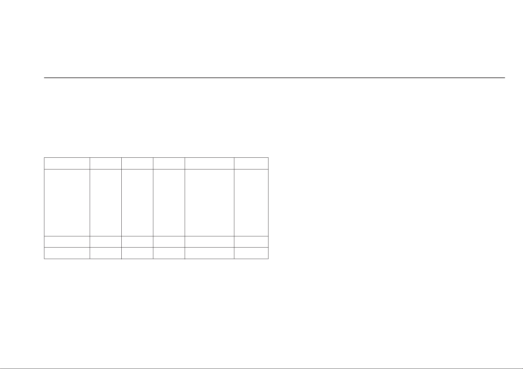
SPECIFICATIONS
Screen dimensions
Preset Image Size
4:3 Diagonal 19.09 inches (485 mm)
Horizontal 15.28 inches (388 mm)
Vertical 11.46 inches (291 mm)
5:4 Diagonal 18.35 inches (466 mm)
Horizontal 14.33 inches (364 mm)
Vertical 11.46 inches (291 mm)
Viewable Image Size (VIS) Diagonal 19.86 inches (504 mm)
Horizontal 15.90 inches (404 mm)
Vertical 11.90 inches (302 mm)
Aperture Grille Pitch 0.24 mm
Deflection angle 90°
Faceplate coating AR Coating
Resolution
Horizontal scan range 30 kHz to 130 kHz (automatic)
Vertical scan range 48 Hz to 170 Hz (automatic)
Optimal preset resolution 1280 x 1024 at 85 Hz
Highest preset resolution 1600 x 1200 at 85 Hz
Highest addressable resolution* 2048 x 1536 at 80 Hz
Electrical
Video input signals analog, 0.7 Vpp, positive at 75 ohm
Synchronization input signals separate horizontal and vertical; and
AC input voltage / frequency / 120 to 240 VAC / 50 or 60 Hz ± 3 Hz /
current 1.6 A (RMS) at 120 VAC and
Inrush current at 120 V 50 A
Inrush current at 240 V 80 A
Physical Characteristics
Connector type 15-pin D-subminiature
Signal cable type Attached to monitor
Dimensions:
Height 502 mm (19.8 inches)
Width 497 mm (19.6 inches)
Depth 485 mm (19.1 inches)
Weight (monitor only) 30.5 kg (67.4 lb)
Weight (with packaging) 35.5 kg (78.4 lb)
US Model
Canadian Model
Chassis No. SCC-L33H-A
CR1
composite TTL level, positive or
negative Sync on Green at 0.3 Vp-p
0.9 A (RMS) at 220 VAC
CHASSIS
* Addressable means the monitor will sync up to this mode. However, Dell
does not guarantee the image will be sized and centered correctly.
Dell guarantees image size and centering for all preset modes listed in the
following table.
TORINITRON
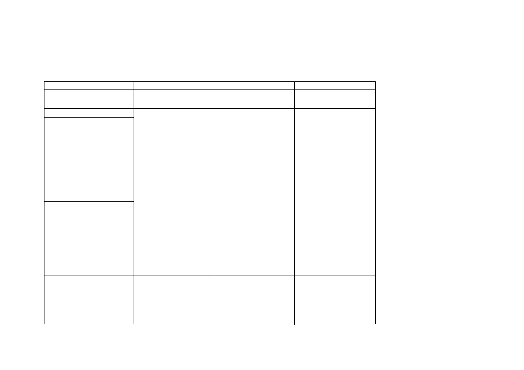
Environmental
Temperature:
Operating 32° to 104°F (0° to 40°C)
Nonoperating -4° to 140°F (-20° to 60°C)
Humidity:
Operating 10% to 80% (noncondensing)
Nonoperating 5% to 90% (noncondensing)
Altitude:
Operating 3,048 m (10,000 ft)
Nonoperating 10,675 m (35,000 ft)
Thermal dissipation 494 BTU/hour (maximum)
®
COLOR GRAPHIC DISPLAY
426 BTU/hour (typical)
R
POWER SAVING FUNCTION
If you have VESA's DPMS compliance display card or software installed in
your PC, the monitor can automatically reduce its power consumption when
not in use. If input from keyboard, mouse or other input devices is detected,
the monitor will automatically "wake up". The following table shows the
power consumption and signaling of this automatic power saving feature:
Power Management Definition
VESA's Mode Video H-sync V-sync Power Used LED color
minimum
95 W
ON Active Yes Yes
Active-OFF Blanked No No < 3 W Amber
OFF* N/A N/A N/A 0 W OFF
maximum
Green
135 W
typical
120 W
This monitor is ENERGY STAR®-compliant and TCO'95 power
management compatible.
* Zero power consumption in OFF mode can only be achieved by
disconnecting the power cable from the monitor.
P1130(E) 4

DIAGNOSIS
Failre
+B failure
Horizontal / Vertical Deflection
failure, Thermal protector
ABL protector
HV failure
Aging / Self Test
Out of scan range
Self Test (OSD Color Bar) : During Power Save, push up UP button for longer than 2 second.
Amber → Off
(0.5 sec) (0.5 sec)
Amber → Off
(1.5 sec) (0.5 sec)
Amber → Off
(0.5 sec) (1.5 sec)
Amber → Off → Amber → Off
(0.25 sec) (0.25 sec) (0.25 sec) (1.25 sec)
Amber → Off → Green → Off
(0.5 sec) (0.5 sec) (0.5 sec) (0.5 sec)
Green (OSD indication)
Power LED
P1130(E) 5
TIMING SPECIFICATION
MODE AT PRODUCTION
RESOLUTION
CLOCK
— HORIZONTAL —
H-FREQ
H. TOTAL
H. BLK
H. FP
H. SYNC
H. BP
H. ACTIV
— VERTICAL —
V. FREQ (Hz)
V. TOTAL
V. BLK
V. FP
V. SYNC
V. BP
V. ACTIV
— SYNC —
INT(G)
EXT (H/V) /POLARITY
EXT (CS) /POLARITY
INT/NON INT
MODE 1 MODE 2 MODE 3
640 X 480 1600 X 1200
25.175 MHz 229.500 MHz
31.469 kHz 106.250 kHz
usec usec
31.778 9.412
6.356 2.440
0.636 0.279
3.813 0.837
1.907 1.325
25.422 6.972
59.940 Hz 85.000 Hz
lines lines
525 1250
45 50
10 1
23
33 46
480 1200
NO NO
YES N/N YES P/P
NO NO
NON INT NON INT
1280 X 1024
157.500 MHz
91.146 kHz
usec
10.971
2.844
0.406
1.016
1.422
8.127
85.024 Hz
lines
1072
1024
NO
YES P/P
NO
NON INT
48
1
3
44
2001.3.21 VER.
P1130(E) 6
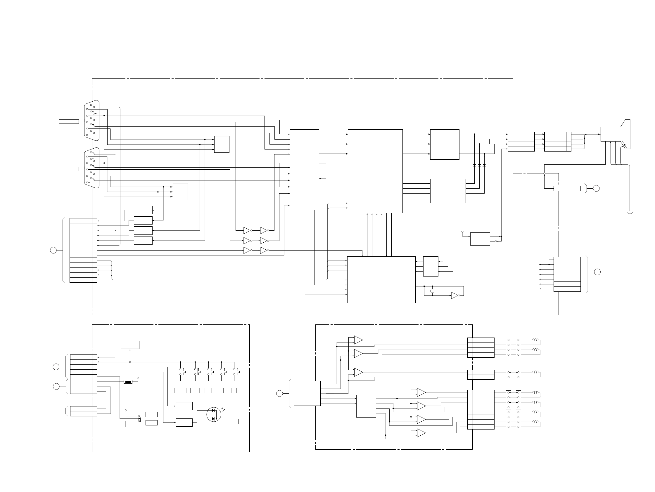
4-1. BLOCK DIAGRAMS
CN309
HD15
5
15
10
14
4
9
3
13
CN307
HD15
CN311
DDC SCL1
DDC SDA1
DDC GND1
DDC SCL2
DDC SDA2
DDC GND2
H BLK
INPUT SW
IIC SCL
IIC SDA
HS OUT
VS OUT
ECO SW
8
2
12
7
1
11
6
5
15
10
14
4
9
3
13
8
2
12
7
1
11
6
SW
Q004
10
11
9
7
8
6
SW
Q005
SW
Q002
SW
Q001
1
4
SCL
15
SDA
16
HS OUT
2
VS OUT
3
ECO SW
13
(VIDEO AMP, RGB OUT)
A1
A
TO D BOARD
CN1102
INPUT2(HD15)
INPUT1(HD15)
SECTION 4
DIAGRAMS
5
SDA
6
SCL
7
VCLK
IC007
ROM
IC008
INPUT SELECT
2
5
SDA
6
SCL
7
VCLK
IC009
ROM
IC006
INVERTER
985 6
3 4 11 10
1 2 13 12
B1
4
G1
6
R1
7
V1
8
H1
10
B2
12
G2
14
R2
15
V2
16
H2
13
SW
18 19 21
R OUT
G OUT
B OUT
SOG
SYNC IN
H OUT
V OUT
25
28
31
23
22
G.SYNC
SCL
SDA
SCL
SDA
HS OUT
VS OUT
ECO SW
7
R IN
4
G IN
2
B IN
22
SCL
23
SDA
4
SCL
3
SDA
12
HS OUT
13
VS OUT
27
ECO SW
23
CS IN
24
VS IN
25
HS IN
RGB PRE-AMP
OSD R
15 14 13 12
18 20 19 21
2
H FLY
OSD R
IC001
OSD G
OSD B
OSD B
OSD G
IC003
OSD BLK
101718
OSD BLK
OSD
7
V_DET
BLK
11
10
AV
BLK
R OUT
G OUT
B OUT
COF R
COF G
COF B
CLAMP
CLP
26
28
30
22
23
24
RCI
GCI
BCI
XTAL IN
15
14
13
32
31
30
14
8
R IN
9
G IN
11
B IN
RIN
GIN
BIN
BUFFER
Q101,
Q201,
Q301
IC002
RGB AMP
IC004
CUT OFF AMP
R_IK
12 11 10
X001
24.5MHz
5
R OUT
3
G OUT
1
B OUT
3
ROUT
5
GOUT
7
BOUT
G_IK
B_IK
7V
2
24
IC005
INVERTER
IC011
HEATER REG
Vcc OUT
VADJ
5
3
1
7
CN315
KR
KG
KB
HEATER+
CN318
KR
KG
KB
HEATER+
5
3
V901
PICTURE TUBE
1
7
FVFCHV
G2
CN318
G2
1
4
5
B
TO D BOARD
FBT
CN312
+B
+B
+80V
+12V
7V
3.3V
5V
1
+B
2
+80V
4
+12V
6
7V
7
3.3V
8
5V
9
C
TO D BOARD
CN604
D
TO D BOARD
CN1103
E
TO N BOARD
CN1003
TO MAGNETIC
SENSOR UNIT
CN1400
WAKE UP
KEY SCAN
LED1
LED2
INPUT SW
T_AMB
VY
VX
CN1401
VX
VY
2
3
4
5
8
12
13
14
3
2
(USER CONTROL)
H4
Q1402
TH1400
5V
5V
S1403
INPUT1
INPUT2
S1401
CONT
LED DRIVE
Q1400
LED DRIVE
Q1401
S1400
S1402OKS1404-S1405
BRT
G
A
+
D1400
POWER
F
TO D BOARD
CN1106
CN1603
GXSC
GYSC
LCC NS
IIC SDA
IIC SCL
4
5
6
7
8
L2
(CY, LCC)
4
3
6
7
1
2
21
20
+
–
+
–
IC1603
+
–
SDA
SCL
IC1600
2
(1/2)
IC1600
8
(2/2)
4
IC1602
DAC
AO2
AO1
AO4
AO3
CN1601
CY4+
3
CY4–
4
CY3+
1
CY3–
2
CN1600
12LCC-NS (+)
LCC-NS (–)
IC1601
4
2
+
(1/2)
3
2
1
4
3
–
IC1601
6
8
+
(2/2)
7
–
IC1604
4
2
+
(1/2)
3
–
IC1604
6
8
+
(2/2)
7
–
1
2
3
4
5
6
7
8
CN1602
LCC-LT (+)
LCC-LT (–)
LCC-LB (+)
LCC-LB (–)
LCC-RT (+)
LCC-RT (–)
LCC-RB (+)
LCC-RB (–)
LCC-NS
LCC-LT
LCC-LB
LCC-RT
LCC-RB
B-SS9328<U/C>-BD1-EPS05
P1130(E) 4-1
 Loading...