

Page 1

Dell™ P o werVault™ TL2000 Tape Library and TL4000
Tape Library
User’s Guid e
Page 2

Page 3

Dell™ P o werVault™ TL2000 Tape Library and TL4000
Tape Library
User’s Guid e
Page 4

Information in this document is subject to change without notice.
© 2008 Dell Inc. All rights reserved.
Reproduction in any manner whatsoever without the written permission of Dell Inc. is strictly forbidden.
Trademarks used in this text: Dell, the DELL logo and PowerVault are trademarks of Dell Inc.
Other trademarks and trade names may be used in this document to refer to either the entities claiming the marks
and names or their products. Dell Inc. disclaims any proprietary interest in trademarks and trade names other than
its own.
Dell PowerVault TL2000/TL4000
Page 5

Read this First
Minimum Firmware Levels for Common Library Features
Contacting Dell
Table 1. Minimum Firmware Levels for common Library features
Feature Minimum Firmware Level(s) Required
Dedicated Cleaning Slot removal Library firmware level must be greater than
3.90.
Encryption Library firmware level must be 5.80 or
greater.
LTO 4 Drive firmware level must be 77BE or
greater.
Key Path Diagnostics Library firmware level must be greater than
6.3, if feature is available.
Path Failover LTO 4 Tape Drives: No minimum level of
firmware is required.
Library firmware must be greater than 5.80.
IPv6 Support Library firmware level: 4.50
LT04 Drive Support Library firmware level: 3.90
For customers in the United States, call 800-WWW-DELL (800-999-3355).
Note: If you do not have an active Internet connection, you can find contact
information on your purchase invoice, packing slip, bill, or Dell product
catalog.
Dell provides several online and telephone-based support and service options.
Availability varies by country and product, and some services may not be available
in your area. To contact Dell for sales, technical support, or customer service
issues:
1. Visit http://support.dell.com.
2. Verify your country or region in the Choose A Country/Region drop-down
menu at the bottom of the page.
3. Click Contact Us on the left side of the page.
4. Select the appropriate service or support link based on your need.
5. Choose the method of contacting Dell that is convenient for you.
iii
Page 6

iv Dell PowerVault TL2000 Tape Library and TL4000 Tape Library User's Guide
Page 7

Contents
Read this First . . . . . . . . . . . . iii
Minimum Firmware Levels for Common Library
Features . . . . . . . . . . . . . . . iii
Contacting Dell . . . . . . . . . . . . . iii
Figures . . . . . . . . . . . . . . vii
Tables . . . . . . . . . . . . . . .ix
Safety and Environmental Notices . . .xi
Danger Notice . . . . . . . . . . . . .xi
Caution Notice . . . . . . . . . . . . .xi
Laser Safety and Compliance . . . . . . . . xii
Class I Laser Product . . . . . . . . . . xii
Performing the Safety Inspection Procedure . . . xii
Rack Safety . . . . . . . . . . . . . . xiii
Preface . . . . . . . . . . . . . .xv
Related Publications . . . . . . . . . . .xv
Chapter 1. Product Description . . . . 1-1
Front Panel . . . . . . . . . . . . . . 1-1
Rear Panel . . . . . . . . . . . . . . 1-3
Internal View of Library . . . . . . . . . . 1-5
Bar Code Reader . . . . . . . . . . . . 1-6
Encryption . . . . . . . . . . . . . . 1-6
Supported Internet Protocols . . . . . . . . 1-8
SNMP Messaging . . . . . . . . . . . . 1-8
Maximum Library Storage Capacity and Data
Transfer Rate . . . . . . . . . . . . . 1-8
Ultrium Tape Drives . . . . . . . . . . . 1-9
Speed Matching . . . . . . . . . . . 1-10
Channel Calibration . . . . . . . . . . 1-10
Power Management . . . . . . . . . . 1-11
Media . . . . . . . . . . . . . . . 1-11
Library Specifications . . . . . . . . . . 1-11
Product Environment . . . . . . . . . . 1-13
Supported Device Drivers . . . . . . . . . 1-13
Chapter 2. User Interfaces . . . . . . 2-1
Operator Control Panel . . . . . . . . . . 2-1
Operator Control Panel Philosophy . . . . . 2-1
Power-ON Display . . . . . . . . . . . 2-2
Note about the Front Panel LEDs . . . . . . 2-2
Input Modes . . . . . . . . . . . . . 2-3
Power ON/OFF . . . . . . . . . . . 2-4
Web User Interface . . . . . . . . . . . . 2-4
Login . . . . . . . . . . . . . . . 2-5
System Status . . . . . . . . . . . . 2-6
Web User Interface Help Pages . . . . . . 2-7
Logging out of the Web User Interface . . . . 2-7
Chapter 3. Installation Planning . . . . 3-1
Determining the Number of Logical Libraries . . . 3-1
Basic Guidelines . . . . . . . . . . . 3-1
Library Sharing . . . . . . . . . . . . 3-1
Using Multiple Logical Libraries for Library
Sharing . . . . . . . . . . . . . . 3-2
Using Multiple Control Paths . . . . . . . . 3-2
Using Multiple Control Paths for Path Failover 3-2
Library Partitioning and Element Addressing . . . 3-3
Logical Unit Number (LUN) Scanning . . . . . 3-6
Host Interfaces . . . . . . . . . . . . . 3-6
SCSI Interface . . . . . . . . . . . . 3-6
SAS Interface . . . . . . . . . . . . 3-8
Fibre Channel Interface . . . . . . . . . 3-8
Chapter 4. Installation and
Configuration . . . . . . . . . . . 4-1
Installing Your Library . . . . . . . . . . 4-1
Using the Library Configuration Form . . . . 4-1
Choosing a Location . . . . . . . . . . 4-1
Unpacking the Library . . . . . . . . . 4-2
Verifying the Shipment . . . . . . . . . 4-2
Installing the Library Foot Pads (for Desktop
Installation ONLY) . . . . . . . . . . . 4-3
Removing and Storing the Shipping Lock . . . 4-4
Rackmounting the Library (for Rack Installation
ONLY) . . . . . . . . . . . . . . . 4-6
Connecting the Host Interface Cable . . . . 4-12
Connecting a Power Cord . . . . . . . . 4-13
Configuring Your Library . . . . . . . . . 4-14
Choosing Your Configuration Method . . . . 4-14
Using Factory Defaults as Your Configuration 4-15
Configuring Your Library using the Web User
Interface . . . . . . . . . . . . . . 4-15
Preparing the Host . . . . . . . . . . . 4-29
Verifying the Connection . . . . . . . . . 4-29
Cartridge Magazines . . . . . . . . . . . 4-30
Populating the Library with Data Cartridges 4-33
Inserting the Cleaning Cartridge . . . . . . 4-34
Chapter 5. Operations . . . . . . . . 5-1
Operator Control Panel Navigation . . . . . . 5-9
Operator Control Panel Menu Tre e . . . . . . 5-10
Monitor Menu . . . . . . . . . . . . 5-11
Control Menu . . . . . . . . . . . . 5-16
Configure Menu . . . . . . . . . . . 5-18
Service Menu . . . . . . . . . . . . 5-26
Web User Interface Menus . . . . . . . . . 5-29
Monitor Library Menu . . . . . . . . . 5-30
Configure Library Menu . . . . . . . . 5-38
Manage Library Menu . . . . . . . . . 5-49
Service Library Menu . . . . . . . . . 5-50
Import and Export Media during Normal Library
Operation . . . . . . . . . . . . . . 5-55
Configuring I/O Stations and Reserving Slots . . 5-57
Chapter 6. Using Ultrium Media . . . . 6-1
v
Page 8

Data Cartridges . . . . . . . . . . . . . 6-1
Cartridge Compatibility . . . . . . . . . 6-2
WORM (Write Once, Read Many) . . . . . . . 6-2
WORM Media . . . . . . . . . . . . 6-3
Data Security on WORM Media . . . . . . 6-3
WORM Media Errors . . . . . . . . . . 6-3
Cleaning Cartridge . . . . . . . . . . . . 6-3
Bar Code Label . . . . . . . . . . . . . 6-4
Guidelines for Using Bar Code Labels . . . . 6-5
Write-Protect Switch . . . . . . . . . . . 6-5
Handling the Cartridges . . . . . . . . . . 6-6
Provide Training . . . . . . . . . . . 6-6
Ensure Proper Packaging . . . . . . . . 6-6
Provide Proper Acclimation and Environmental
Conditions . . . . . . . . . . . . . 6-7
Perform a Thorough Inspection . . . . . . 6-7
Handle the Cartridge Carefully . . . . . . 6-8
Environmental and Shipping Specifications for Tape
Cartridges . . . . . . . . . . . . . . 6-8
Chapter 7. Troubleshooting . . . . . 7-1
Installation Problems . . . . . . . . . . . 7-1
Maintenance Problems . . . . . . . . . . 7-2
Library Recovery Problem Determination . . . . 7-7
Procedures for Isolating CRU Problems . . . . . 7-8
Isolating a Power Supply Problem . . . . . 7-8
Isolating Drive Sled Problems . . . . . . . 7-10
Isolating a Library Controller Card vs. Accessor
Enclosure Problem . . . . . . . . . . 7-11
Isolating We b User Interface Problems . . . . 7-11
Isolating Accessor Scanner Problems . . . . 7-12
Isolating Host Attachment Interface Problems 7-12
Identifying a Suspect Cartridge . . . . . . . 7-12
Chapter 8. Error Codes . . . . . . . 8-1
Preparing the Defective Library for
Replacement . . . . . . . . . . . . 10-10
Unpacking and Preparing the Replacement
Library Enclosure . . . . . . . . . . 10-12
Swapping Library Controller Cards . . . . 10-15
Installing Your Drive(s) in the Replacement
Library Enclosure . . . . . . . . . . 10-17
Swapping Cartridge Magazines . . . . . . 10-19
Swapping Power Supplies . . . . . . . 10-22
Installing the Replacement Library Enclosure 10-23
Completing the Installation of the
Replacement Library Enclosure . . . . . . 10-25
Returning the Defective Library . . . . . 10-25
Appendix A. SCSI Element Types and
Addresses . . . . . . . . . . . . . A-1
2U Library I/O Slot, Storage Slots and Drive Slot
Element Addresses and Physical Locations . . .A-1
4U Library I/O Slots, Storage Slots, and Drive
Slots Element Addresses and Physical Locations .A-2
Library Partitioning and Element Addressing . .A-2
Appendix B. TapeAlert Flags . . . . . B-1
TapeAlert Flags Supported by the Library . . . . B-1
TapeAlert Flags Supported by the Drive . . . . B-3
Appendix C. Sense Data . . . . . . . C-1
Library Sense Data . . . . . . . . . . . C-1
Drive Sense Data . . . . . . . . . . . . C-6
Appendix D. Enabling LUN Support in
Linux . . . . . . . . . . . . . . . D-1
Red Hat Enterprise Linux . . . . . . . . .D-2
Enabling LUN Support in Netware . . . . . .D-2
Chapter 9. Service Procedures . . . . 9-1
Removing Cartridges from Magazine Slots . . . . 9-1
Releasing the Magazines Manually . . . . . . 9-1
Using the ITDT Firmware Update, Dump Retrieval
and Drive Test Tool . . . . . . . . . . . 9-5
Appendix E. Notes on IPv6
Compatibility with Windows 2003/XP
and 2008/Vista . . . . . . . . . . . E-1
Notes on IPv6 Compatibility with Linux . . . . E-2
Appendix F. Library Configuration
Chapter 10. Check, Adjust, Remove,
Form . . . . . . . . . . . . . . . F-1
and Replace . . . . . . . . . . . 10-1
Tools Required . . . . . . . . . . . . . 10-1
Electrostatic Discharge . . . . . . . . . . 10-1
Relocating Your Library . . . . . . . . . . 10-1
Replacing a Tape Drive Sled . . . . . . . . 10-3
Replacing a Power Supply . . . . . . . . . 10-7
Replacing a Library Controller Card . . . . . 10-8
Replacing Cartridge Magazines . . . . . . . 10-10
Replacing the Library Enclosure . . . . . . 10-10
Notices . . . . . . . . . . . . . . G-1
Trademarks . . . . . . . . . . . . . .G-1
Glossary . . . . . . . . . . . . . H-1
Index . . . . . . . . . . . . . . . X-1
vi Dell PowerVault TL2000 Tape Library and TL4000 Tape Library User's Guide
Page 9

Figures
1-1. Front panel of a 2U library . . . . . . 1-1
1-2. Front panel of a 4U library . . . . . . 1-2
1-3. Rear panel of a 2U library with a SCSI drive 1-3
1-4. Rear panel of a 4U library with Full height
Fibre Channel drive and Half height SCSI
and SAS drives . . . . . . . . . . 1-4
1-5. Rear panel of a 2U library with a full height
dual port SAS drive . . . . . . . . . 1-4
1-6. Internal view of the library . . . . . . 1-5
1-7. Library drive sled without ESD springs
(SCSI sled shown) . . . . . . . . . 1-10
1-8. Library drive sled with ESD springs [1]
(SAS sled shown) . . . . . . . . . 1-10
2-1. Power-ON Screens . . . . . . . . . 2-2
2-2. Web User Interface login page . . . . . 2-6
2-3. 2U library System Status screen . . . . . 2-6
2-4. 4U library System Status screen . . . . . 2-6
2-5. 4U library System Status screen showing a
power supply failure . . . . . . . . 2-7
3-1. Configuration of a One Partition System 3-4
3-2. Configuration of a Tw o Partition System 3-4
3-3. Configuration of a Three Partition System 3-4
3-4. Configuration of a Four Partition System 3-5
3-5. Examples of SCSI Element Addressing 3-5
4-1. Removing the plastic protective sheets from
the library . . . . . . . . . . . . 4-2
4-2. Installing foot pads on the bottom of the
library enclosure . . . . . . . . . . 4-4
4-3. Shipping lock and label . . . . . . . 4-5
4-4. Removing the Shipping lock and label 4-5
4-5. Library shipping lock and label storage
location on rear panel of library . . . . . 4-6
4-6. Rack Kit Mounting hardware . . . . . . 4-7
4-7. Examples of EIA units for round hole and
square hole installations . . . . . . . 4-8
4-8. Rear view of a rack showing the narrow
part of the rail . . . . . . . . . . . 4-8
4-9. Front view of a rack showing the rails
installed . . . . . . . . . . . . . 4-9
4-10. 2U library side screws to remove . . . . 4-9
4-11. 2U library rack anchors and mounting
brackets . . . . . . . . . . . . . 4-9
4-12. Sliding the 2U library into the rack 4-10
4-13. Sliding the 4U library into the rack 4-10
4-14. Securing the 2U library to the rack 4-11
4-15. Securing the 4U library to the rack 4-11
4-16. Attaching SCSI ([1]), Fibre Channel ([4]),
and SAS ([2]) cables to the 4U library . . 4-12
4-17. Removing the protective label from the
power receptacle . . . . . . . . . 4-13
4-18. Log in screen on the Web User Interface 4-17
4-19. The 2U library Configure Library: General
screen . . . . . . . . . . . . . 4-19
4-20. Example: The 4U library Configure
Library: General screen . . . . . . . 4-20
4-21. The 4U library Configure Library: Logical
Libraries page . . . . . . . . . . 4-21
4-22. The Configure Library: Path Failover
Feature Activation screen . . . . . . . 4-21
4-23. Feature Key verification screen . . . . . 4-21
4-24. Feature Activation Key screen . . . . . 4-22
4-25. Configure Library: Encryption Activation
screen . . . . . . . . . . . . . 4-22
4-26. The Configure Library: Drive screen 4-23
4-27. Configure Library: Network page 4-24
4-28. Warning screen . . . . . . . . . . 4-24
4-29. The Configure Library: User Access screen 4-26
4-30. The Configure Library: Date and Time
screen . . . . . . . . . . . . . 4-27
4-31. The Configure Library: Logs and Traces
screen . . . . . . . . . . . . . 4-27
4-32. The Configure Library: Event Notification
screen . . . . . . . . . . . . . 4-28
4-33. 2U library left magazine . . . . . . . 4-30
4-34. 2U library right magazine . . . . . . 4-30
4-35. 2U library I/O Station in the left magazine 4-31
4-36. 4U library left magazines . . . . . . . 4-31
4-37. 4U library right magazines . . . . . . 4-32
4-38. 4U library I/O Station in the lower left
magazine . . . . . . . . . . . . 4-32
4-39. Finger Holes on back side of 4U library
I/O Station . . . . . . . . . . . 4-33
5-1. 2U Library Control Keys . . . . . . . 5-9
5-2. 4U Library Control Keys . . . . . . . 5-9
5-3. Operator Control Panel Menu Tre e 5-11
5-4. Monitor: Library menu . . . . . . . 5-12
5-5. Monitor: Drive menu . . . . . . . . 5-14
5-6. Example of a 4U Monitor: Inventory menu 5-15
5-7. Overview of inventoried cartridges: Lower
Left Magazine of a 4U Library . . . . . 5-16
5-8. Control: I/O Station menu . . . . . . 5-16
5-9. Control: Move Cartridges menu 5-17
5-10. Control: Magazine menu . . . . . . . 5-17
5-11. Control: Re-Inventory menu . . . . . . 5-18
5-12. Configure: Logical Libraries menu 5-19
5-13. Configure: Library menu . . . . . . . 5-20
5-14. Configure: Drive menu . . . . . . . 5-22
5-15. Configure: Network menu . . . . . . 5-23
5-16. Configure: Set Access PIN menu 5-24
5-17. Configure: Restore Defaults menu 5-24
5-18. Configure: Set Date and Time menu 5-26
5-19. Configure: Path Failover . . . . . . . 5-26
5-20. Service: Library Verify menu . . . . . 5-27
5-21. Service: Run Tests menu . . . . . . . 5-27
5-22. Service: Service menu . . . . . . . . 5-28
5-23. Service: Display Contrast menu 5-29
5-24. The 2U library Monitor Library: Library
Identity page . . . . . . . . . . . 5-31
5-25. The 4U library Monitor Library: Library
Identity page . . . . . . . . . . . 5-31
vii
Page 10

5-26. The 4U library Monitor Library: Drive
Identity page showing one Fibre Channel
drive (#1) and one SCSI drive (#2) . . . . 5-33
5-27. The 4U library Monitor Library: Library
Status page . . . . . . . . . . . 5-34
5-28. The 4U library Monitor Library: Drive
Status page . . . . . . . . . . . 5-36
5-29. The 2U library Monitor Library: Inventory
page . . . . . . . . . . . . . 5-37
5-30. The 4U library Monitor Library: Inventory
page . . . . . . . . . . . . . 5-38
5-31. The 4U library Configure Library: General
and Extended page . . . . . . . . . 5-40
5-32. The 4U library Configure Library: Logical
Libraries page . . . . . . . . . . 5-40
5-33. The 4U library Configure Library: Path
Failover page . . . . . . . . . . 5-41
5-34. Path Failover license verification page 5-41
5-35. Feature Activation Key screen . . . . . 5-42
5-36. Configure Library: Encryption Feature
configuration screen . . . . . . . . 5-42
5-37. The Configure Library: Drive page for a
4U library . . . . . . . . . . . . 5-44
5-38. Configure Library: Network page 5-45
5-39. Warning screen . . . . . . . . . . 5-45
5-40. Configure Library: User Access page 5-47
5-41. The Configure Library: Date & Time page 5-47
5-42. Configure Library: Logs & Traces page 5-48
5-43. Configure Library: Event Notification page 5-48
5-44. Configure Library: Restore Defaults page 5-49
5-45. Manage Library: Move Media page 5-49
5-46. Manage Library: Perform Inventory page 5-50
5-47. Manage Library: Release Magazine page 5-50
5-48. Service Library: Clean Drive page 5-51
5-49. Service Library: View Logs page 5-51
5-50. Service Library: View Drive Logs screen 5-52
5-51. Service: Save Drive Dump . . . . . . 5-52
5-52. Service Library: Perform Diagnostics page 5-53
5-53. Service Library: Perform Key Path
Diagnostics page . . . . . . . . . 5-53
5-54. The 2U library Service Library: Upgrade
Firmware page . . . . . . . . . . 5-54
5-55. The 4U library Service Library: Upgrade
Firmware page . . . . . . . . . . 5-55
5-56. Service Library: Reboot page . . . . . 5-55
6-1. The LT O Ultrium 800 GB Data Cartridge 6-1
6-2. Ultrium WORM Tape Cartridge . . . . . 6-3
6-3. Sample bar code label on the LTO Ultrium 4
Tape Cartridge . . . . . . . . . . 6-5
6-4. Setting the write-protect switch . . . . . 6-6
6-5. Double-boxing tape cartridges for shipping 6-7
6-6. Checking for gaps in the seams of a
cartridge . . . . . . . . . . . . 6-8
7-1. A 250w power supply with LEDs 7-8
7-2. A 80w power supply without LEDs 7-9
9-1. Access holes for the left magazine 9-2
9-2. Access holes for the right magazine 9-3
9-3. Left Magazines pulled out of the 2U library 9-4
9-4. Left Magazines pulled out of the 4U Library 9-4
10-1. Shipping lock and label storage location 10-2
10-2. Shipping lock and label . . . . . . . 10-2
10-3. Library drive sled without ElectroStatic
Discharge (ESD) springs (SCSI sled shown) 10-3
10-4. Library drive sled with ESD springs [1]
(SAS sled shown) . . . . . . . . . 10-4
10-5. Drive sled components (full-high fibre
drive in top position, half-high SCSI drive
in middle position, half-high SAS drive in
bottom position) on back panel of a 4U
library . . . . . . . . . . . . . 10-4
10-6. Pulling the drive sled out of the library
(drive sled without ESD springs shown) . 10-5
10-7. Pushing the drive sled into the library
(drive sled without ESD springs shown) . 10-6
10-8. Diagrams for applying conductive tape for
ESD protection to the back of a drive sled
installed in a 2U or 4U library . . . . . 10-7
10-9. A power supply being removed from a 2U
library . . . . . . . . . . . . . 10-8
10-10. A Library Controller Card being removed
from the library . . . . . . . . . . 10-9
10-11. Rear panel of a 4U library with a Fibre
Channel full height drive in the top
position, a SCSI half height drive in the
middle position, and a SAS half height
drive in the bottom position . . . . . 10-11
10-12. Removing the two mounting bracket
screws anchoring the library to the rack
(one screw on each side of the library . . 10-11
10-13. Foot pads installed on the bottom of the
library enclosure . . . . . . . . . 10-13
10-14. Removing the shipping label and lock
from the top of the library and storing on
the rear panel . . . . . . . . . . 10-14
10-15. Library shipping lock and label storage
location on the real panel of the library . 10-14
10-16. Removing a Library Controller Card from
the library . . . . . . . . . . . 10-16
10-17. Library Front Panel LEDs . . . . . . 10-17
10-18. Removing a drive sled from the library
(drive sled without ESD springs shown) . 10-18
10-19. Drive sled taping diagrams . . . . . 10-19
10-20. Access hole for the left magazine (facing
rear of library) . . . . . . . . . . 10-20
10-21. Access hole for the right magazine (facing
rear of library) . . . . . . . . . . 10-21
10-22. Left magazine pulled out of a 4U library
(facing front of library) . . . . . . . 10-22
10-23. A power supply being removed from a
library . . . . . . . . . . . . 10-23
10-24. Mounting brackets and anchors for
securing the library in a rack (one bracket
and anchor on each side of the library) . . 10-24
10-25. Front view of a rack showing the rails
installed . . . . . . . . . . . . 10-24
A-1. Configuration of a One Partition System A-3
A-2. Configuration of a Tw o Partition System A-4
A-3. Configuration of a Three Partition System A-4
A-4. Configuration of a Four Partition System A-5
A-5. Examples of SCSI Element Addressing A-5
viii Dell PowerVault TL2000 Tape Library and TL4000 Tape Library User's Guide
Page 11

Tables
1. Minimum Firmware Levels for common
Library features . . . . . . . . . . iii
1-1. 2U library and 4U library front panel
descriptions . . . . . . . . . . . 1-2
1-2. 2U library and 4U library rear panel
descriptions . . . . . . . . . . . 1-4
1-3. Internal view description . . . . . . . 1-6
1-4. Tape drive model and interface type 1-8
1-5. Library storage capacity and data transfer
rate . . . . . . . . . . . . . . 1-9
3-1. Host Drive Interface Support . . . . . . 3-6
3-2. Maximum bus length between terminators 3-7
3-3. Recommended maximum quantity of drives
per SCSI bus . . . . . . . . . . . 3-7
4-1. Location criteria . . . . . . . . . . 4-1
5-1. Menu navigation shortcuts . . . . . . 5-1
5-2. Library Control Keys . . . . . . . . 5-9
5-3. Factory Default Settings . . . . . . . 5-25
5-4. Web User Interface Menus . . . . . . 5-29
5-5. Library Identity page elements . . . . . 5-30
5-6. Drive Identity page elements . . . . . 5-31
5-7. Library Status page elements . . . . . 5-33
5-8. Drive Status page elements . . . . . . 5-34
5-9. Configure Library: General page elements 5-39
5-10. Configure Library: Specific page elements 5-39
5-11. Drive Identity page elements . . . . . 5-43
6-1. Ultrium data and cleaning cartridge
compatibility with Ultrium tape drive . . . 6-2
6-2. Cartridges and VOLSERs compatible with
the Ultrium 3 and Ultrium 4 Tape Drive . . 6-4
6-3. Environment for operating, storing, and
shipping the LTO Ultrium Tape Cartridge . 6-9
7-1. Troubleshooting table . . . . . . . . 7-5
7-2. Power Supply LED Meanings . . . . . 7-9
8-1. Error Codes . . . . . . . . . . . 8-2
8-2. Sub error codes . . . . . . . . . . 8-8
10-1. . . . . . . . . . . . . . . . 10-17
A-1. 2U library SCSI Element Types and
Element Addresses . . . . . . . . .A-1
A-2. 4U library SCSI Element Types and
Element Addresses . . . . . . . . .A-1
A-3. 2U library SCSI element addresses for
storage slots and drive slot . . . . . .A-1
A-4. 4U library SCSI element addresses for
storage slots and drive slot . . . . . .A-2
B-1. TapeAlert Flags Supported by the Ultrium
Tape Drive . . . . . . . . . . . . B-3
C-1. Library Sense Keys, ASC and ASCQ C-1
C-2. LTO Tape Drive Sense Data . . . . . . C-6
ix
Page 12

x Dell PowerVault TL2000 Tape Library and TL4000 Tape Library User's Guide
Page 13
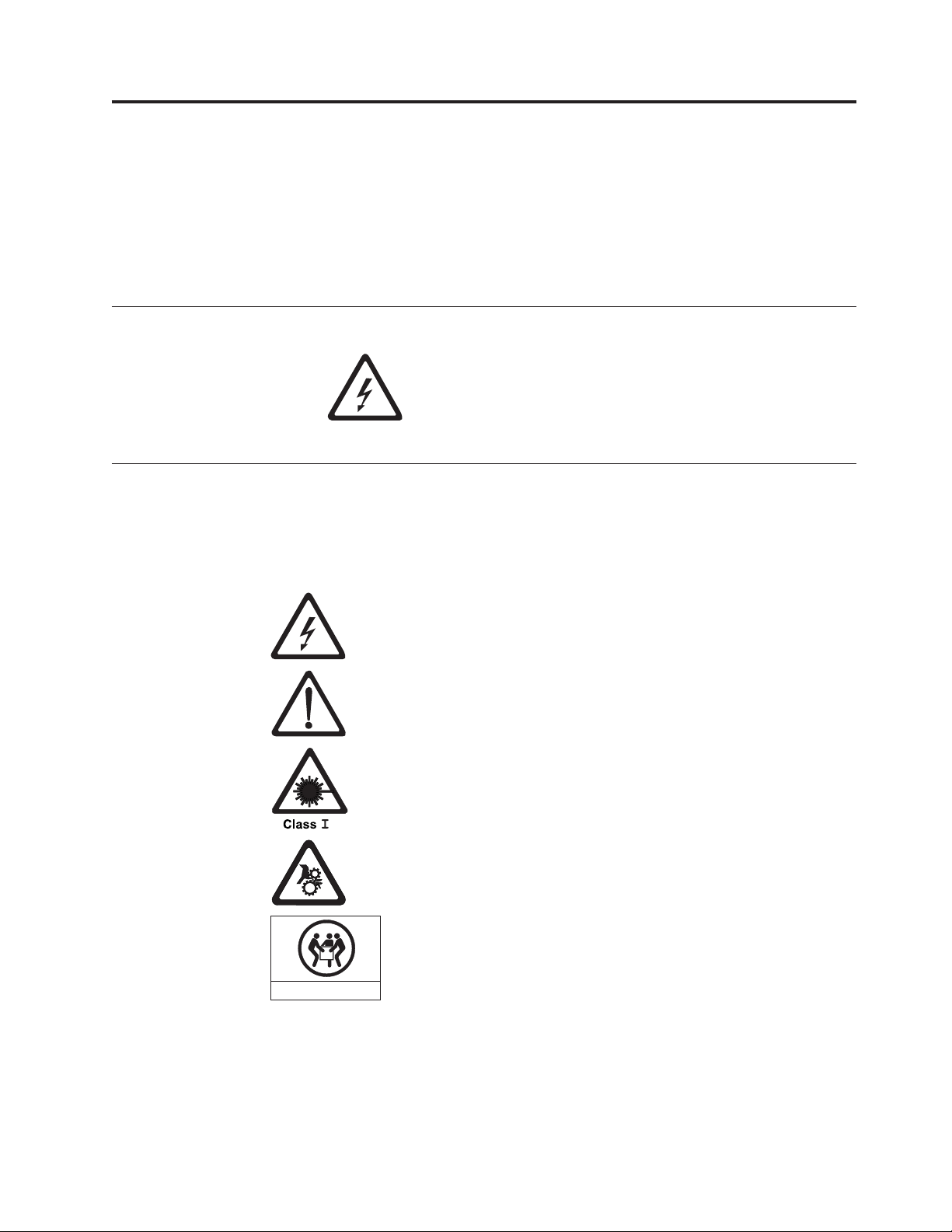
Safety and Environmental Notices
When using this product, observe the danger, caution, and attention notices that
are contained in this guide. The notices are accompanied by symbols that represent
the severity of the safety condition.
The sections that follow define each type of safety notice and give examples.
Danger Notice
Caution Notice
A caution notice calls attention to a situation that is potentially hazardous to
people because of some existing condition. A caution notice can be accompanied
by one of several symbols:
A danger notice calls attention to a situation that is
potentially lethal or extremely hazardous to people. A
lightning bolt symbol always accompanies a danger notice
to represent a dangerous electrical condition.
If the symbol is... It means....
A hazardous electrical condition with less severity than electrical
danger.
A generally hazardous condition not represented by other safety
symbols.
A hazardous condition due to the use of a laser in the product. Laser
symbols are always accompanied by the classification of the laser as
defined by the U. S. Department of Health and Human Services (for
example, Class I, Class II, and so forth).
A hazardous condition due to mechanical movement in or around the
product.
A hazardous condition due to the weight of the unit. Weight symbols
are accompanied by an approximation of the product’s weight.
32-55 kg (70.5-121.2 lbs)
svc00168
xi
Page 14

Laser Safety and Compliance
Before using the library, review the following laser safety information.
Class I Laser Product
The library may contain a laser assembly that complies with the performance
standards set by the U.S. Food and Drug Administration for a Class I laser
product. Class I laser products do not emit hazardous laser radiation. The library
has the necessary protective housing and scanning safeguards to ensure that laser
radiation is inaccessible during operation or is within Class I limits. External safety
agencies have reviewed the library and have obtained approvals to the latest
standards as they apply.
Performing the Safety Inspection Procedure
Before you service the unit, perform the following safety inspection procedure:
1. Stop all activity between the host and the library’s tape drives.
2. Turn off the power to the library by pushing in on the Power button (1)
shown in Figure 1-1 on Page 1-1 for 4 seconds.
3. If drives are SCSI attached, disconnect the SCSI cable and check the SCSI bus
terminator for damage.
4. Unplug the library’s power cord or cords from the electrical outlet and the
library power supply.
5. Check the library’s power cord for damage, such as a pinched, cut, or frayed
cord.
6. If drives are SCSI attached, check the tape drive’s SCSI bus (signal) cable for
damage.
7. If drives are FC/SAS attached, check the tape drive’s FC/SAS cable for
damage.
8. Check the cover of the library for sharp edges, damage, or alterations that
expose its internal parts.
9. Check the cover of the library for proper fit. It should be in place and secure.
10. Check the product label at the rear of the library to make sure that it matches
the voltage at your outlet.
xii Dell PowerVault TL2000 Tape Library and TL4000 Tape Library User's Guide
Page 15

Rack Safety
The following general safety information should be used for all rack mounted
devices.
DANGER
Always lower the leveling pads on the rack cabinet.
v
v Always install stabilizer brackets on the rack cabinet.
v To avoid hazardous conditions due to uneven mechanical loading, always
install the heaviest devices in the bottom of the rack cabinet. Always install
servers and optional devices starting from the bottom of the rack cabinet.
v Rack mounted devices are not to be used as a shelf or work space. Do not
place any object on top of rack mounted devices.
v Each rack cabinet might have more than one power cord. Ensure that all
power cords in the rack cabinet are disconnected before servicing any
device in the rack cabinet.
v Connect all devices installed in a rack cabinet to power devices installed in
the same rack cabinet. Do not plug a power cord from a device installed in
one rack cabinet into a power device installed in a different rack cabinet.
v An electrical outlet that is not correctly wired could place hazardous
voltage on the metal parts of the system or the devices that attach to the
system. It is the responsibility of the customer to ensure that the outlet is
correctly wired and grounded to prevent an electrical shock.
CAUTION:
v Do not install a unit in a rack where the internal rack ambient temperatures
will exceed the manufacturer’s recommended ambient temperature for all your
rack mounted devices.
v Do not install a unit in a rack where the air flow is compromised. Ensure that
air flow is not blocked or reduced on any side of the unit.
v Connect the equipment to the supply circuit such that overloading of the
circuits does not compromise the supply wiring or overcurrent protection. To
provide the correct power connection to a rack, refer to the rating labels
located on the equipment in the rack to determine the total power
requirement of the supply circuit.
v (For sliding drawers) Do not pull out or install any drawer or feature if the rack
stabilizer brackets are not attached to the rack. Do not pull out more than one
drawer at a time. The rack may become unstable if you pull out more than
one drawer at a time.
v (For fixed drawers) Do not move a fixed drawer. Attempting to move the drawer
partially or completely out of the rack may cause the rack to become unstable
or cause the drawer to fall out of the rack.
Safety and Environmental Notices xiii
Page 16

CAUTION:
Removing components from the upper positions in the rack cabinet improves
rack stability during relocation. Follow these general guidelines whenever you
relocate a populated rack cabinet within a room or building:
v Reduce the weight of the rack cabinet by removing equipment starting at the
top of the rack cabinet. When possible, restore the rack cabinet to the
configuration of the rack cabinet as you received it. If this configuration is not
known, you must do the following:
– Remove all devices in the 32U position and above.
– Ensure that the heaviest devices are installed in the bottom of the rack
cabinet.
– Ensure that there are no empty U-levels between devices installed in the
rack cabinet below the 32U level.
If the rack cabinet you are relocating is part of a suite of rack cabinets, detach
v
the rack cabinet from the suite.
v Inspect the route that you plan to take to eliminate potential hazards.
v Verify that the route that you choose can support the weight of the loaded
rack cabinet. Refer to the documentation that comes with your rack cabinet for
the weight of a loaded rack cabinet.
v Verify that all door openings are at least 762 x 2032 mm (30 x 80 in.).
v Ensure that all devices, shelves, drawers, doors, and cables are secure.
v Ensure that the four leveling pads are raised to their highest position.
v Ensure that there is no stabilizer bracket installed on the rack cabinet during
movement.
v Do not use a ramp inclined at more than ten degrees.
v Once the rack cabinet is in the new location, do the following:
– Lower the four leveling pads.
– Install stabilizer brackets on the rack cabinet.
– If you removed any devices from the rack cabinet, repopulate the rack
cabinet from the lowest position to the highest position.
If a long distance relocation is required, restore the rack cabinet to the
v
configuration of the rack cabinet as you received it. Pack the rack cabinet in
the original packaging material, or equivalent. Also lower the leveling pads to
raise the casters off of the pallet and bolt the rack cabinet to the pallet.
xiv Dell PowerVault TL2000 Tape Library and TL4000 Tape Library User's Guide
Page 17

Preface
This manual contains information and instructions necessary for the installation,
operation, and service of the Dell™ PowerVault™ TL2000 Tape Library and TL4000
Tape Library.
Related Publications
Refer to the following publications for additional information.
v Getting Started with the Dell™ PowerVault™ TL2000 and TL4000 Tape Libraries
provides installation information.
v Dell™ PowerVault™ TL2000 Tape Library and TL4000 Tape Library SCSI Reference
provides supported SCSI commands and protocol governing the behavior of
SCSI interface.
xv
Page 18

xvi Dell PowerVault TL2000 Tape Library and TL4000 Tape Library User's Guide
Page 19
Chapter 1. Product Description
The Dell™ PowerVault™ TL2000 Tape Library (2U library) and the Dell PowerVault
TL4000 Tape Library (4U library) provide compact, high-capacity, low-cost
solutions for simple, unattended data backup. The 4U library houses up to 48 tape
cartridges (or 45 and an elective 3-slot I/O Station) in a compact 4U form factor
with easy access to cartridges via four removable magazines. The 2U library
houses up to 24 tape cartridges (or 23 and an elective 1-slot I/O Station) in a
compact 2U form factor with easy access to cartridges via two removable
magazines.
The TL2000/TL4000 Library supports LT03 and LT04 tape drives with these
interfaces: a Small Computer Systems Interface (SCSI), Fibre Channel interface
(FC), or Serial Attached SCSI interface (SAS). LTO 3 and LTO 4 Half height drives
are SAS only, and LTO 4 Full height drives are SAS and Fibre Channel only. LTO3
full height drives are SCSI and Fibre Channel only.
Front Panel
3
8
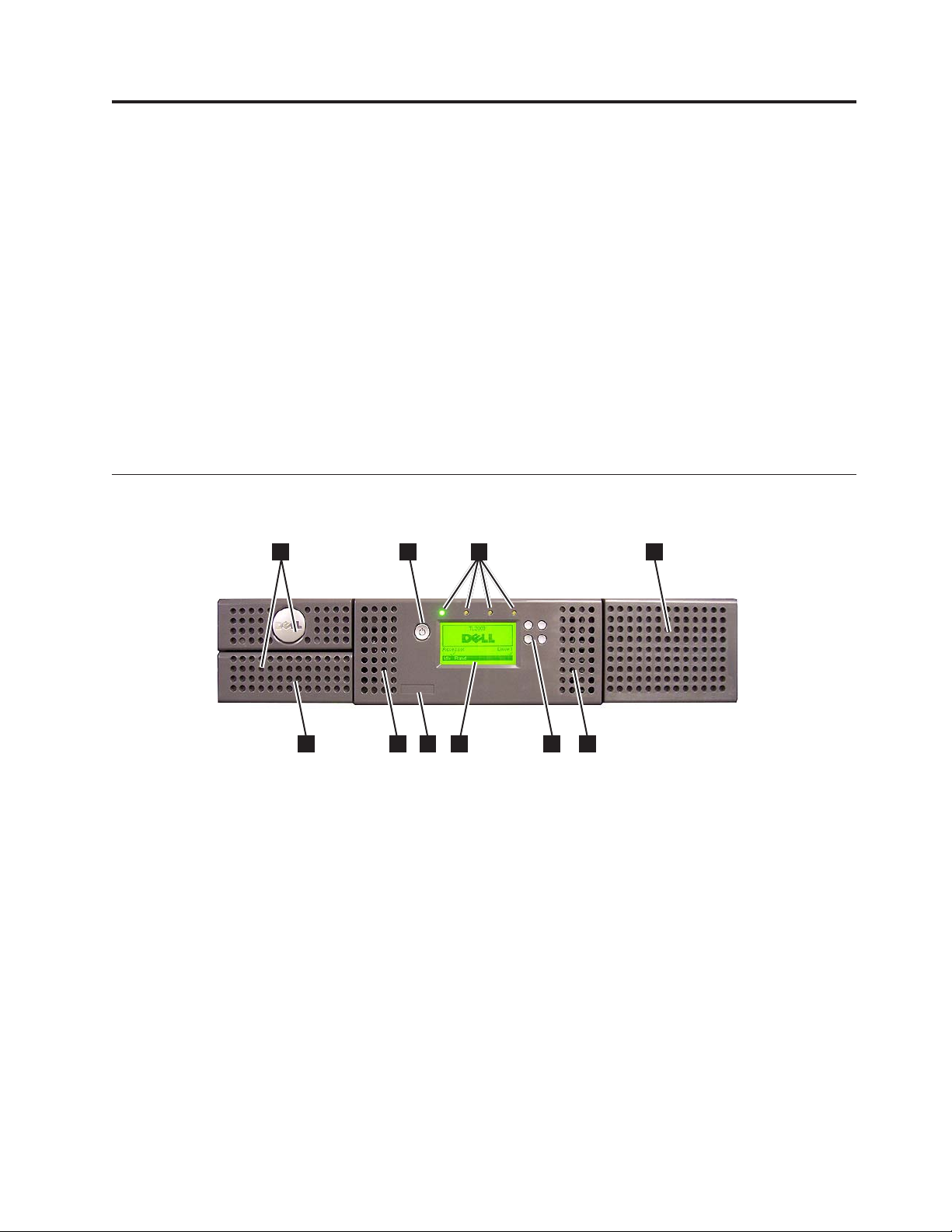
Figure 1-1. Front panel of a 2U library
1 2
7
6
3
a77ug173
5
44
1-1
Page 20
8
1 2
6 7
4
33
a77ug172
5
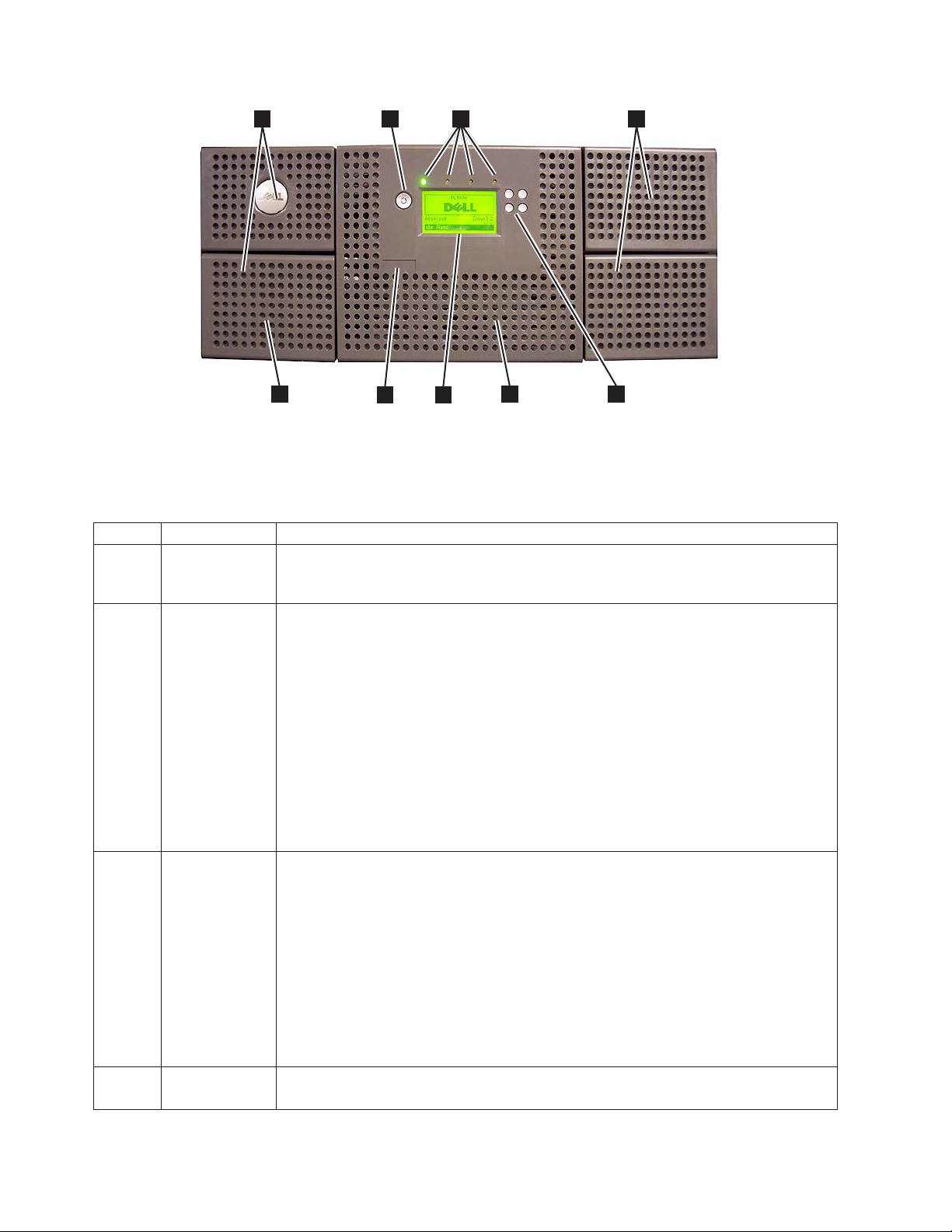
Figure 1-2. Front panel of a 4U library
Table 1-1 below contains front panel descriptions for both the 2U library in
Figure 1-1 on page 1-1 and the 4U library in Figure 1-2.
Table 1-1. 2U library and 4U library front panel descriptions
Number Item Description
1 Power button Pressing this button will power ON the library. Pressing and holding this button for 4
seconds will power OFF the unit (soft power down). No power switch or button can
be found on the back panel of the library.
2 Front panel
LEDs (left to
right)
3 Cartridge
magazines
4 Air vents These vents draw cooler air into the library enclosure and allow warm air to escape
v Ready/Activity (Green LED) - It is lit any time the unit is powered ON and able to
function. It should blink whenever there is library or drive activity, or when the
library is in the process of powering up.
v Clean Drive (Amber LED) - It will be lit when the drive needs to be cleaned. The
LED will be turned OFF after the drive is cleaned successfully.
v Attention (Amber LED) - It will be lit when there has been a failure that indicates a
piece of media is bad, marginal, or invalid. It will be cleared when all invalid
cartridges have been exported from the library. The amber LED may also be lit
because a power supply or a power supply fan is failing, or a drive sled is defective,
missing, or has been replaced by a different drive type.
v Error (Amber LED) - It will be lit when there is an unrecoverable library or drive
failure. A message is displayed at the same time on the Operator Control Panel
display.
v The 2U library contains two cartridge magazines.
– The left magazine can hold up to 12 cartridges (or 11 data cartridges and the
elective 1-slot I/O Station.)
– The right magazine can hold up to 12 cartridges.
The 4U library contains four cartridge magazines.
v
– The upper left magazine can hold up to 12 cartridges.
– The lower left magazine can hold up to 12 cartridges (or 9 data cartridges and the
elective 3-slot I/O Station.)
– The upper right magazine can hold up to 12 cartridges.
– The lower right magazine can hold up to 12 cartridges.
which helps keep the library at a normal operating temperature.
1-2 Dell PowerVault TL2000 Tape Library and TL4000 Tape Library User's Guide
Page 21
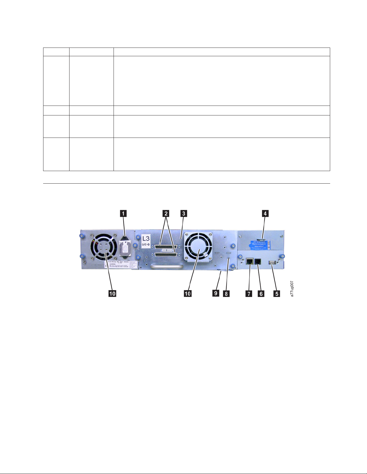
Table 1-1. 2U library and 4U library front panel descriptions (continued)
Number Item Description
5 Control keys
v UP (+) - The upper left button is used to scroll upward through menu items.
v DOWN (-) - The lower left button is used to scroll downward through menu items.
v CANCEL (X) - The upper right button is used to cancel a user action and return to
the previous menu screen.
v SELECT - The lower right button is used to display a sub-menu or force an accessor
action.
6 Service Tag This service tag links the library to your warranty.
7 Operator
This component is a 128 X 64 monochrome graphic display.
Control Panel
display
8 I/O Station The Input/Output (I/O) Station is used to import and export cartridges into and out
of the library.
v The 2U library has an elective 1-slot I/O Station.
v The 4U library has an elective 3-slot I/O Station.
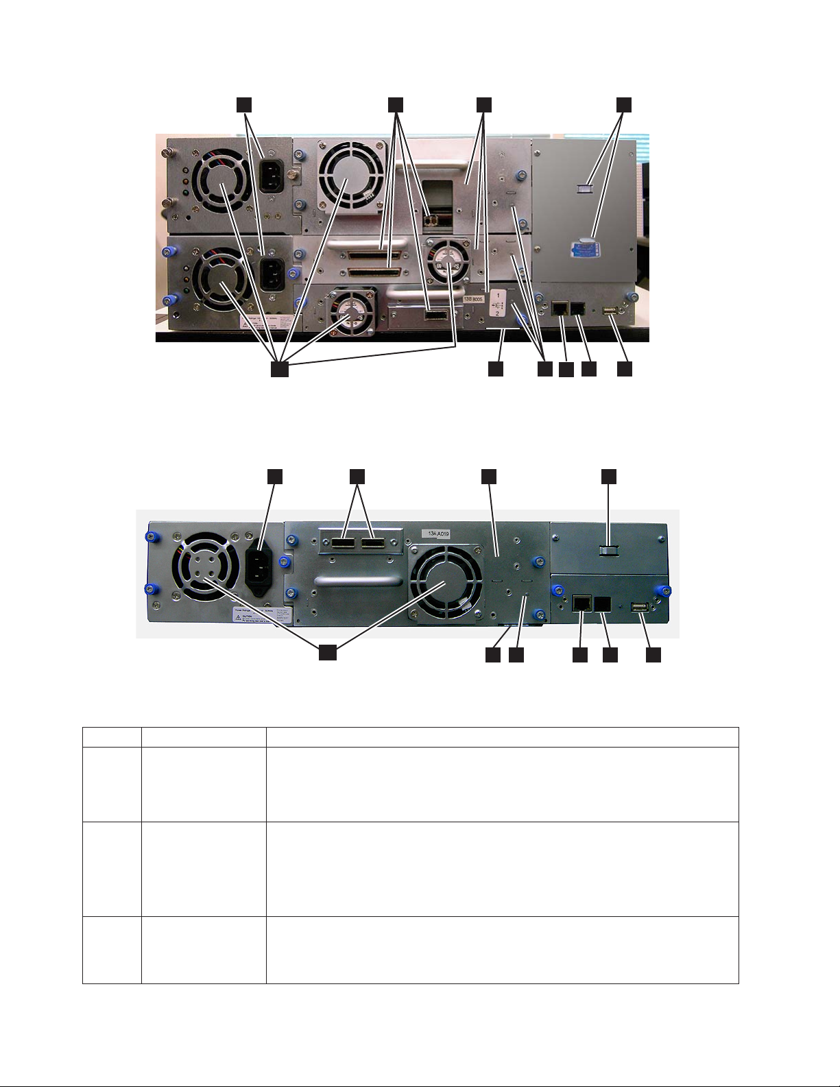
Rear Panel
Figure 1-3. Rear panel of a 2U library with a SCSI drive
Chapter 1. Product Description 1-3
Page 22
1
10
3
9
8
7
42
a77ug100
5
6
Figure 1-4. Rear panel of a 4U library with Full height Fibre Channel drive and Half height SCSI and SAS drives. The
configuration shown in this figure is used as an example only. This configuration is not recommended. Half height
SCSI drives are not supported on the TL2000/TL4000.
1
2
3
4
10
8
9
6
7
5
Figure 1-5. Rear panel of a 2U library with a full height dual port SAS drive
Table 1-2. 2U library and 4U library rear panel descriptions
Number Item Description
1 Power connector(s) Both libraries require a 110/220 volt AC power connection.
v The 2U library has one power supply.
v The 4U library has a minimum of one power supply, but has the capability of
adding a redundant power supply.
2 Host interface
connectors
The library has one or more of the following host interface connectors on the drive
sled:
v a 68-pin HD SCSI connector
v a Fibre Channel connector
v a SFF-8088 mini-SAS connector
3 Tape drive sled This library supports the Ultrium 3 and Ultrium 4 Tape Drive. The tape drive in
the library is packaged in a container called a drive sled. Drive sleds come in a
Full height or Half height configuration. The drive sled is a customer replaceable
unit (CRU), and is hot-pluggable - designed for easy removal and replacement.
1-4 Dell PowerVault TL2000 Tape Library and TL4000 Tape Library User's Guide
a77ug135
Page 23

Table 1-2. 2U library and 4U library rear panel descriptions (continued)
Number Item Description
4 Shipping lock and
label storage
location
The shipping lock, which secures the accessor during shipping, and associated
label are stored on the rear panel of the library for future use. See “Removing and
Storing the Shipping Lock” on page 4-4.
Attention:
The shipping lock must be removed before powering ON the library
to allow the accessor to function properly.
5 USB port An alternative communication path to the library. For use by Service Personnel.
6 Serial port This port is used to communicate serially with the library using an RJ-11 connector.
For use by Service Personnel.
7 Ethernet port This port is used to connect the library to a network.
8 Tape drive LED This LED indicates the current status of the drive. When the LED is green, it
indicates normal drive activity.
9 Service Tag/Serial
Number
The service tag and serial number on the pull-out label links the library to your
warranty.
10 Fan vents These vents allow air to escape from the power supply and tape drive sled.
Internal View of Library
Important: FOR REFERENCE ONLY. The customer is not authorized to remove
the top cover of the library. No customer serviceable components are
inside the library.
2
3
4
1
Figure 1-6. Internal view of the library
5
6
a77ug124
Chapter 1. Product Description 1-5
Page 24

Table 1-3. Internal view description
Number Item Description
1 Right cartridge
magazine(s)
2 Left cartridge
magazine(s)
3 Accessor This component contains the library robot and bar code reader. The accessor
4 Library Controller Card This component is a customer replaceable unit (CRU) and stores the user
5 Tape drive sled Both libraries support the Ultrium 3 and Ultrium 4 Tape Drive. Each tape
6 Power supply The power supply is a customer replaceable unit (CRU) and the sole source of
v In a 2U library, the right magazine can hold up to 12 cartridges.
v In a 4U library, the right magazines can hold up to 24 cartridges.
v In a 2U library, the left magazine can hold up to 11 cartridges and houses
the elective 1-slot I/O Station.
v In a 4U library, the left magazines can hold up to 21 cartridges and houses
the elective 3-slot I/O Station.
moves cartridges to/from the following:
v I/O Station
v storage slots
v tape drive(s)
configuration information or vital product data (VPD).
drive in the library is packaged in a container called a drive sled. The drive
sled is a customer replaceable unit (CRU), and is designed for easy removal
and replacement.
v The 2U library houses one full height tape drive sled or up to two half
height tape drive sleds.
v The 4U library houses up to two full height tape drive sleds or up to four
half height tape drive sleds. Combinations of full height and half height
drive sleds are allowed.
power for the library. The 2U has one power supply. The 4U has one or can
have an optional second power supply for redundancy.
Bar Code Reader
The bar code reader is an integral part of the library accessor. The bar code reader
provides inventory feedback to the host application, Operator Control Panel
display, and Web User Interface by reading cartridge bar code labels. The library
stores the customized inventory data in memory.
Library firmware supports a 6 or 8 character volume serial number (VOLSER) on
the bar code label on the tape cartridge. Bar code selection is available for libraries
with library code 4.50 or greater.
Encryption
The LTO Ultrium 4 Tape Drive supports Application Managed Encryption (AME),
and Library Managed Encryption (LME), using T10 encryption methods, for SAS
and Fibre Channel drives only. Data encryption is supported with LTO Ultrium 4
Data Cartridges only. Encryption is also supported with library firmware version
5.80 and higher and drive firmware version 77BE and greater.
The encryption enabled drive contains the necessary hardware and firmware to
encrypt and decrypt host tape application data. Encryption policy and encryption
keys are provided by the host application or host server. A drive digital certificate
1-6 Dell PowerVault TL2000 Tape Library and TL4000 Tape Library User's Guide
Page 25

is installed at manufacturing time. Each drive receives a unique serial number and
certificate. The T10 application may validate each drive instance by checking the
drive’s digital certificate.
CAUTION:
The library must be offline from any user and all media must be removed from
the drives before license keys are installed or any configuration modifications
are made. Please refer to “Power ON/OFF” on page 2-4 and “Removing
Cartridges from Magazine Slots” on page 9-1 for instructions to take the library
offline and to eject media from the drives.
To prevent possible data loss due to an EKM server failure, Dell recommends
the use of a primary and secondary EKM server. This configuration provides
redundancy in the event the primary EKM server is down or unavailable. Please
refer to Chapter 2 (Multiple Key Managers for Redundancy) of the Dell
Encryption Key Manager User’s Guide and to “Configure Library: Encryption”
on page 5-41 for information on configuring a primary and secondary EKM for
your library.
If the backup job fails due to an EKM server failure, the job will recover if
connectivity is restored to the EKM server prior to expiration of the timeout set
in the tape backup software application.
Enabling library-managed encryption on a PowerVault TL2000 or TL4000 is a 6
step process.
1. Upgrade the library and drive firmware to the latest versions. The firmware
can be found at http://support.dell.com.
2. Enable library-managed encryption on the library via the license key if not
already licensed. Please refer to Figure 2-25 for activation instructions. .
If you purchased library-managed encryption at the time you purchased your
library, a hard copy of the license key is provided with your library as a
backup. If there are any issues with the license key for library-managed
encryption purchased with the library, please visit http://www.dell.com/
tapeautomation to obtain your license key. You will need the library serial
number and worldwide node name to obtain the license key. Please refer to the
following tables in this document for instructions on locating this information:
v Table 1.2 for library serial number
v Table 4.5 for library worldwide node name
If this does not resolve your issue, please contact Dell technical support.
3. Configure library-managed encryption on your library. Please refer to Figure
2-26 for instructions.
4. Install the Dell Encryption Key Manager (EKM) application on the server
designated for EKM. Please refer to Chapter 3.0 of the Dell Encryption Key
Manager User’s Guide for instructions. This document can be found at
http://support.dell.com.
5. Configure the EKM application. Please refer to Chapter 4.0 of the Dell
Encryption Key Manager User’s Guide for instructions.
6. Start the EKM application. Please refer to Chapter 5.0 of the Dell Encryption Key
Manager User’s Guide for instructions.
All encryption settings should be configured or re-verified in the drive after
Note:
any library or drive reset. This is because a new drive may have been added
or an existing drive may have been swapped with another drive.
Chapter 1. Product Description 1-7
Page 26

Supported Internet Protocols
The library supports the following Internet protocols:
v IPv4
v IPv6
learn more about IPv4, visit http://www.iana.org/. To learn more about IPv6,
To
visit http://www.ipv6.org/.
SNMP Messaging
Occasionally, the library may encounter a situation that you want to know about,
such as an open magazine or a fault that causes the library to stop. The library
provides a standard TCP/IP protocol called Simple Network Management Protocol
(SNMP) to send alerts about conditions (such as need for operator intervention)
over a TCP/IP LAN network to an SNMP monitoring station. These alerts are
called SNMP traps. Using the information supplied in each SNMP trap, the
monitoring station (together with customer-supplied software) can alert operations
personnel of possible problems or operator interventions that occur.
In summary, each trap provides the following information:
v Product Identification such as product name, description, manufacturer, model
number, firmware level, and the URL that the trap is designated for.
v Product Status such as the severity of the trap, status (current and previous) and
the time the trap occurred.
v Library State (physical device status) such as identification and status of devices
that are monitored. In the case of the library, it would include enclosure, power
supply, controller, magazine status, drive count, cartridge slot count, and I/O
station count. Also included would be certain library statistics, and where
appropriate, the fault FSC (fault symptom code) including the severity and
description of that fault.
v Drive Status such as the identification of each drive in the library, firmware
level, serial number and other address and status information.
v Trap Definitions such as library status change, open magazine, I/O accessed,
hard fault information, drive cleaning requests, excessive retries and library
returning to normal operations.
Maximum Library Storage Capacity and Data Transfer Rate
Maximum library storage capacity and maximum data transfer rates are as follows:
Table 1-4. Tape drive model and interface type
Tape Drive Model Host Interface
Ultrium 4 Full height drives
Ultrium 4 Half height drives
Ultrium 3 Full height drives
Ultrium 3 Half height drives
1-8 Dell PowerVault TL2000 Tape Library and TL4000 Tape Library User's Guide
v 4 Gb/s Fibre Channel
v 3 Gb/s Serial Attached SCSI (SAS) - dual port
v 3 Gb/s SAS - single port
v Ultra160 SCSI LV D (depending on drive; single-ended (SE) is not
recommended as it will severely degrade performance)
v 4 Gb/s Fibre Channel
v 3 Gb/s SAS - single port
Page 27

Table 1-5. Library storage capacity and data transfer rate
Characteristic 2U Library Specification 4U Library Specification
Maximum storage capacity Ultrium 4 Data Cartridges
Maximum storage capacity Ultrium 3 Data Cartridges
v 24 data cartridges
v Native: 19.2 TB
v Compressed: 38.4 TB (2:1
compression)
v 24 data cartridges
v Native: 9.6 TB
v Compressed: 19.2 TB (2:1
compression)
v 48 data cartridges
v Native: 38.4 TB
v Compressed: 75.2 TB (2:1
compression)
v 48 data cartridges
v Native: 19.2 TB
v Compressed: 38.4 TB (2:1
compression)
Maximum data transfer rate LTO 3 HH: Native: 60 MBs
LTO 3 FH: Native: 80 MBs (288 GB/hr.)
Compressed: 160 MBs (576 GB/hr.) (2:1 compression)
LTO 4 HH and FH: Native: 120 MBs
Compressed: 240 MBs (2:1 compression)
Ultrium Tape Drives
This library supports the Ultrium 3 and Ultrium 4 Tape Drives. Each tape drive in
the library is packaged in a container called a drive sled. The drive sled is a
customer replaceable unit (CRU), and is designed for quick removal and
replacement in the library.
The Ultrium 4 Full height Tape Drives support SAS, or Fibre Channel interfaces. It
features two SFF-8088 SAS connectors, or one LC Fibre Channel connector. The
Ultrium 4 Half height Tape Drive supports one SAS SFF-8088 connector.
The Ultrium 3 Full height Tape Drive supports LVD Ultra160, or Fibre Channel
interfaces. It features two HD68 connectors or one LC Fibre Channel connector. The
Ultrium 3 Half height Drive supports one SAS SFF-8088 connector.
Chapter 1. Product Description 1-9
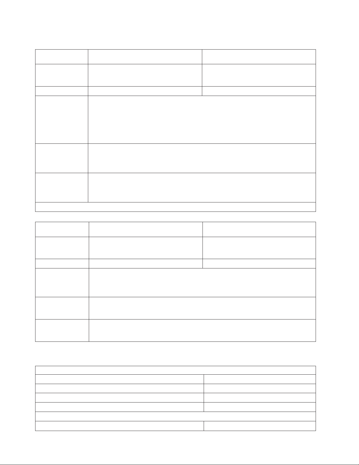
Page 28
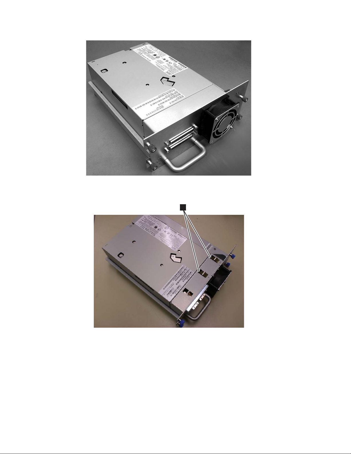
Figure 1-7. Library drive sled without ESD springs (SCSI sled shown)
a77ug008
1
Figure 1-8. Library drive sled with ESD springs [1] (SAS sled shown)
Speed Matching
To improve system performance, the Ultrium 3 and Ultrium 4 Tape Drive uses a
technique called speed matching to dynamically adjust its native (uncompressed)
data rate to the slower data rate of the attached server.
a77ug202
Channel Calibration
The channel calibration feature of the Ultrium 3 and Ultrium 4 Tape Drive
customizes each read/write data channel for optimum performance. The
customization enables compensation for variations in the recording channel
transfer function, media characteristics, and read/write head characteristics.
1-10 Dell PowerVault TL2000 Tape Library and TL4000 Tape Library User's Guide
Page 29

Media
Power Management
The Ultrium 3 and Ultrium 4 Tape Drive’s power management function controls
the drive’s electronics so that part of the electronics completely turn OFF when
circuit functions are not needed for the drive’s operation.
The library uses Ultrium Tape Cartridges that provide up to 800 GB native
capacity (up to 1600 GB with 2:1 hardware data compression) for LTO-4 tape
drives, and up to 400 GB native capacity (up to 800 GB with 2:1 hardware data
compression) for LTO-3 tape drives.
Ultrium 4 tape drives can read and write LTO Ultrium 3 Data Cartridges at
original Ultrium 3 capacities, and can also read LTO Ultrium 2 Data Cartridges
with improved data rates. Ultrium 3 Tape Drives can read and write LTO Ultrium
2 Data Cartridges at original Ultrium 2 capacities, and can also read LTO Ultrium 1
Data Cartridges with improved data rates of up to 20 MB/second native data
transfer rate (40 MB/second with 2:1 compression). Ultrium 4 tape drives cannot
read Ultrium 1 tapes.
Supported cartridges include:
v LTO Ultrium 800 GB Data Cartridge (Ultrium 4)
v LTO Ultrium 400 GB Data Cartridge (Ultrium 3)
v Write-Once-Read-Many Data Cartridge (WORM; Ultrium 3 and Ultrium 4)
v LTO Ultrium 200 GB Data Cartridge (Ultrium 2)
v 100 GB Data Cartridge (Ultrium 1; read only)
v LTO Ultrium Cleaning Cartridge
For additional information, see Chapter 6, “Using Ultrium Media,” on page 6-1.
Library Specifications
Physical Specifications
Specification 2U library 4U library
Rack mount 87.6 mm (3.44 in),
Height
stand-alone 97.6 mm (3.84 in)
Width 447.5 mm (17.6 in.) 447.5 mm (17.6 in.)
Rack mount 740 mm (29.13 in),
Depth
stand-alone 810 mm (31.9 in)
Weight with 1 drive and without
media 15.59 kg (34.37 lbs.) 21.32 kg (47 lbs.)
Weight with media 20.67 kg (45.57 lbs.) 31.71 kg (69.9 lbs.)
Power Specifications
AC power voltage 100-127 VAC; 200-240 VAC (4 - 2 A)
Line frequency 50-60 Hz
Rack mount 175.2 mm (6.9 in),
stand-alone 185.2 mm (7.3 in)
Rack mount 740 mm (29.13 in),
stand-alone 810 mm (31.9 in)
Chapter 1. Product Description 1-11
Page 30
Operation Specifications
Library with
Ultrium 4 drive(s)
Maximum storage
capacity
Number of slots 24 (including I/O Station) 48 (Including 3 I/O station slots)
Maximum data
transfer rate
(maximum
sustained with
optimally
compressible data MB/sec)
2U Library 4U Library
Maximum number of data cartridges: 24
Native: 19.2 TB
Compressed: 38.4 TB (2:1 compression)
Maximum number of data cartridges: 48
Native: 38.4 TB
Compressed: 75.2 TB (2:1 compression)
Native(FH/HH Drives): 120 MBs
Compressed: 240 MBs (2:1 compression)
Drive types
Ultrium 4 Full height drive
Fibre Channel, SAS
Ultrium 4 Half height Drive: SAS
Interfaces
4 Gb/s Fibre Channel
3 Gb/s SAS
*Host Interface Drive Transfer Rates may vary depending on host usage and interface utilization.
Library with
Ultrium 3 drive(s)
Maximum storage
capacity
2U library 4U library
Maximum number of data cartridges: 24
Native: 9.6 TB
Compressed: 19.2 TB (2:1 compression)
Maximum number of data cartridges: 48
Native: 19.2 TB
Compressed: 38.4 TB (2:1 compression)
Number of slots 24 (including I/O Station) 48 (Including 3 I/O station slots.)
Native for Ultrium 3 Full height: 80 MBs (288 GB/hour)
Maximum data
transfer rate
Compressed for Ultrium 3 Full height: 160 MBs (576 GB/hour (2:1 compression))
Native for Ultrium 3 Half height: 60 MB/s
Compressed for Ultrium 3 Half height: 120 MB/s
Ultrium 3 Full height
Drive types
Drive: SCSI, Fibre Channel
Ultrium 3 Half height Drive: Serial Attached SCSI (SAS)
Ultra160 SCSI LVD
Interfaces
4 Gb/s Fibre Channel
3 Gb/s SAS
Environmental Specifications
Temperature
Operating 10° to 35° C (50° to 95° F)
Storage, without cartridges -30° to 60° C (-22° to 140° F)
Wet bulb, operating 26° C (79.0° F) maximum
Temperature shock immunity - maximum rate of change 10° C (18° F) per hour
Miscellaneous
Dust concentration less than 200 microgram/cubic meter
1-12 Dell PowerVault TL2000 Tape Library and TL4000 Tape Library User's Guide
Page 31

Altitude (operating) 2500 meters (8200 ft.) at 25°C ambient
Maximum acoustical noise sound power levels LwAd in bels 6.6/6.8
Humidity
Operating 15% to 80% RH non-condensing
Storage, without cartridges 10% to 90% RH non-condensing
Product Environment
The library is designed to operate in a general business environment.
The library meets the acoustical requirements for general business area category
2D. Category 2D states that the library should be installed a minimum of 4 m (13
ft.) from a permanent work station.
To allow for service access, install the library a minimum of 0.9 m (3 ft.) from all
obstacles.
The library is a precision computer peripheral. To ensure maximum longevity of
your library, locate the library away from dust, dirt, and airborne particulates:
v Keep the library away from high-traffic areas, especially if the floor is carpeted.
Carpeting harbors dust and people walking on the carpet can cause the carpet
fibers and the dust to become airborne.
v Keep the library out of printer/copier rooms because of toner and paper dust.
Additionally, do not store paper supplies next to the library.
v Keep the library away from moving air caused by doorways, open windows,
fans, and air conditioners.
Ensure that the machine covers are always kept closed to minimize any
contamination from airborne particles.
Supported Device Drivers
The latest levels of device drivers can be downloaded by visiting
http://support.dell.com.
Note: The TL2000 and TL4000 libraries utilize the generic SCSI drivers in RHEL 4
and 5. Depending on the ISV you are using, you will use either the sg or st
driver. Please refer to your ISV documentation for more information on
which driver to use.
Chapter 1. Product Description 1-13
Page 32

1-14 Dell PowerVault TL2000 Tape Library and TL4000 Tape Library User's Guide
Page 33

Chapter 2. User Interfaces
This library has two user interfaces.
v Operator Control Panel - located on the front panel of the library
v Web User Interface - accessed via a web browser
Operator Control Panel
The Operator Control Panel operates in two basic modes.
v User Interaction mode - This mode is employed when a user is pushing buttons
on the Operator Control Panel.
v System Driven mode - This is the normal mode of operation. In this mode, the
Operator Control Panel displays status associated with the actions that were
caused from commands issued via the drive’s internal (drive to library) serial
interface.
When an Operator Control Panel button is pressed and released, the Operator
Control Panel automatically transitions to User Interaction mode. User Interaction
mode will continue until 3 minutes after a user stops pushing buttons, or the
requested accessor action stops - whichever is longer. At which time, the Operator
Control Panel will return to System Driven mode.
If necessary, the Operator Control Panel will automatically transition to the System
Driven mode. When this occurs, the library must remember what the user was
doing before the display mode changed. Therefore the next button pressed will
only transition the Operator Control Panel to the User Interaction mode from the
System Driven mode.
In case of the activated user security feature, the User Interaction mode is
restricted to Login and Monitor menu items, until a user logs in with a correct
password.
Operator Control Panel Philosophy
Operator Control Panel operation must obey some basic rules. These rules of
operation constitute a philosophy.
v Any operational conflict between commands received over the host interface or
the Web User Interface and those entered via the Operator Control Panel will be
avoided with a reservation mechanism on a first-come, first-served basis. Any
reservation by the Operator Control Panel is canceled by an Operator Control
Panel logout or a timeout, which cancels the User Interaction Mode.
v Library firmware will not allow a user to select an impossible request. Those
situations will include, but are not limited to:
– Moving a cartridge from any source to a full slot
– Moving a cartridge from an empty slot
– Loading a cartridge from any source to a full drive
– Unloading a cartridge from an empty drive
Any error detected by the library or drive controller and not recoverable through
v
predetermined firmware algorithms will be considered as fatal. An error code
will be displayed on the Operator Control Panel display and the error LED will
2-1
Page 34

become illuminated. The error code will remain on the Operator Control Panel
until a push button is pressed, which will cause the Operator Control Panel to
return to the Home Screen.
v Numeric error codes are only used for unrecoverable, fatal errors, otherwise text
status messages are displayed.
Power-ON Display
When the library powers ON or resets, it goes through several internally controlled
processes that allow it to get initialized and running. These processes are called
Power-On-Self-Test (POST). During the POST the Operator Control Panel will
display information that may be meaningless until POST is complete. When the
POST is finished, the library will display the current library status in the Home
Screen.
While the library is going through its power up cycle the user can monitor the
state of the library via the OCP; however, the user will not be able to make any
configuration changes until the unit has completed its initialization routine.
Attempts to make changes will be ignored.
Firmware Rev: 120R
Drive: 1
Magazines: 2
I/O Station: empty
Startup
Figure 2-1. Power-ON Screens
Note about the Front Panel LEDs
All LEDs are updated during power ON and reset sequences. Upon power ON or
software reset, the library will illuminate all LEDs as soon as POST allows. When
initialization starts, all LEDs will be extinguished and the Ready/Activity LED will
flash at a rate of approximately one second per cycle. When the mechanical
initialization is complete, the Ready/Activity LED will stop flashing and be
constantly illuminated.
If a library failure occurs, the Ready/Activity LED will turn OFF and the Error
LED will illuminate. The Operator Control Panel will also display an appropriate
error code to help identify the failure.
Idle Random
TL4000
Accessor Drive 1 2
Idle Rand
a77ug187
The following are additional operational details of LEDs:
v The Ready/Activity LED will be lit any time the unit is powered ON and
functional. The Ready/Activity LED will blink whenever there is library or drive
activity. This LED will also blink when the unit is OFFLINE.
2-2 Dell PowerVault TL2000 Tape Library and TL4000 Tape Library User's Guide
Page 35

v The Clean LED will only be lit when a cleaning REQUIRED has been issued by
the drive. The LED will be turned OFF after a successful drive cleaning
operation.
v The Attention LED will indicate one of the following conditions.
Problem Action Required
Bad media
Drive sled issues Do one of the following:
Redundant power supply failed Complete the following steps:
1. Go to Monitor → Inventory to locate the defective
cartridge.
2. Move the defective cartridge to the I/O Station.
(Operator Control Panel: Control → Move Cartridges).
3. Open the I/O Station to remove the defective
cartridge. (Operator Control Panel: Control → Open
I/O).
- Install a drive sled (see “Replacing a Tape Drive Sled”
on page 10-3).
- Modify or resubmit Logical Library setting (Operator
Control Panel: Configure → Logical Libraries or We b
User Interface: Configure Library → Logical Libraries).
- Restore defaults (Operator Control Panel: Configure →
Restore Defaults or We b User Interface: Configure
Library → Restore Defaults). -
1. Replace the failed power supply (see “Replacing a
Power Supply” on page 10-7).
2. Cycle library power.
Power supply fan failure Replace the power supply.
v The Error LED will be lit when there is an unrecoverable (i.e. hard) drive or
library failure. This will happen at the same time the hard error message is
displayed on the screen and the LED will remain lit until the error state is
resolved.
From the Operator Control Panel, run Service → Library Verify. If Library
Note:
Verify runs without error, the Error LED will be turned off. If the error
persists, recycle power.
Input Modes
There are several ways to enter values in the different menu items. These values
are selectable predefined values, toggle values (for example, ON/OFF) and
numerical values like network addresses.
Selecting Predefined Values
1. To set the predefined values, press the SELECT button to select the menu item.
2. Using the UP and DOWN buttons, select one of the various predefined values
for that item.
3. As soon as the Operator Control Panel display shows the correct value, press
the SELECT button to apply the value.
Chapter 2. User Interfaces 2-3
Page 36

Toggling Values
Toggle values are used to switch between two different states like ON and OFF.
1. After navigating to the menu item, press the SELECT button to select the menu
item.
2. Using the UP and DOWN buttons, select one of the various predefined states
for that item.
3. Press the SELECT button to apply the new state.
Entering Numerical Values
Numerical values are needed for network addresses, password entries and other
configuration entries.
1. After navigating to the menu item, the current value is displayed and the
cursor highlights the first digit of the value that can be changed.
2. For each digit to be changed in the value:
a. Use the UP and DOWN buttons to increment / decrement the digit.
b. Press the SELECT button to highlight the next editable digit.
Press the SELECT button at the last digit to apply the complete entry, or press
3.
the CANCEL button to cancel the whole edit process and maintain the original
value.
Power ON/OFF
Part of the Operator Control Panel is the Power ON/OFF button. If the library is
powered ON, pressing this button for 4 seconds will initiate a controlled power
down of the library (soft landing). The following operations will take place before
the library shuts down completely:
v The display indicates with an appropriate message that the shutdown is in
progress.
v The library controller finishes all ongoing library and drive activities.
v The accessor is moved to its home position.
v The library controller switches OFF the power supply’s secondary side.
Note: The shutdown process may be aborted by releasing the button before 4
Web User Interface
Many of the same operations performed from the Operator Control Panel can also
be performed remotely using the Web User Interface.
The Web User Interface lets you monitor and control your library from any
terminal connected to your network or through the World Wide Web (WWW). The
Web User Interface hosts a dedicated, protected Internet site that displays a
graphical representation of your library.
seconds has passed.
For static IP Addresses only: After establishing a connection to the library, open
any HTML browser and enter the IP address of the library. To configure the We b
User Interface, you must first set the IP address using the Operator Control Panel.
2-4 Dell PowerVault TL2000 Tape Library and TL4000 Tape Library User's Guide
Page 37

Login
Important: Some options of the We b User Interface take the library OFFLINE. This
inactive mode can interfere with host-based application software,
causing data loss. Make sure the library is idle before attempting to
perform any remote operations that will take the library OFFLINE.
To login, select the Role type and enter the correct password. The TL4000/TL2000
RMU screen shows Welcome : User, superuser, admin, or service after a successful
login. The user can log out at any time by clicking on the ″logout″ text located in
to top right corner of the RMU page.
v The User account has only viewing privileges to the unit, not able to make any
configuration changes.
v Superuser - The Superuser has access to the Monitor Library and Manage
Library sections.
v The Admin account has access to monitor, configure and run unit diagnostics
(only exception is the advanced diagnostics reserved for service personnel only).
v The Service account has all the same privileges as the Admin account with the
addition of advanced unit diagnostics.
Note: User and Superuser accounts must be enabled by the library
administrator. These accounts are disabled by default.
the following password for logging in as an Admin user: secure
Use
Each level affects which areas you have access to and what actions you can initiate
from those areas.
For DHCP, use the Operator Control Panel to determine the IP Address assigned to
your library. Navigate to Monitor → Library → Identity. Scroll down to IP Address
and make note of the address. Enter the IP Address in your internet browser
address field to access your library with the Web User Interface.
For IPv4 or Dual Stack IPv4 + IPv6, enter your library’s static IP Address using the
0.0.0.0 format (four octets).
For IPv6, enter your library’s static IP Address or Router Assigned IP Address
using the following format: http://[0:0:0:0:0:0:0:0]. To determine your Router
Assigned IP Address, navigate to Monitor → Library → Network on the Operator
Control Panel.
If the dual IP stack is enabled (IPv4 + IPv6), IPv6 addresses cannot be configured
in the OCP (Operator Control Panel) and must be configured through the Web
User Interface. IPv6 addresses can only be configured in the OCP if the IPv6-only
stack is enabled. In the case where the dual stack is enabled, the IPv6 address must
be configured through the web interface (either using the IPv4 address or a known
other IPv6 address).
Chapter 2. User Interfaces 2-5
Page 38

Figure 2-2. Web User Interface login page
System Status
The System Status screen is always present after login giving current status of the
library.
a77ug070
Figure 2-3. 2U library System Status screen
Figure 2-4. 4U library System Status screen
Status icons indicate the following conditions.
v The green check mark indicates that the library is fully operational and that no
user intervention is required.
v The yellow exclamation point indicates that user intervention is necessary, but
that the library is still capable of performing operations. This condition can be
caused by a media, library, redundant power supply, power supply fan, or a
drive sled problem. To determine which, view the System Status screen.
v The red X indicates that user intervention is required and that the library is not
capable of performing operations.
a77ug080
a77ug089
2-6 Dell PowerVault TL2000 Tape Library and TL4000 Tape Library User's Guide
Page 39

v If Auto Clean is enabled and a cleaning cartridge is not present, or if a cleaning
cartridge is present, but not in a reserved slot, Auto Clean status will show Chk
Media/Rsvd Slot? and Status will show a green check mark and the words
Media Attention. The Auto Clean status disappears from the system status
screen once Auto Clean has been properly configured. The user will get
messages if the cleaning media expires.
v The Power Supply Status will only appear if redundant power is being utilized
with a 4U library, and the library was manufactured after March 14, 2008. If a
redundant power supply fails, the System Status screen will appear as shown in
Figure 2-5.
Figure 2-5. 4U library System Status screen showing a power supply failure
Note: If your library has -04 level redundant power supplies (see label on top of
power supply), it is normal for the one in “Standby” mode to turn its
“Green” LED off. You can test this power supply by pulling the power
connector from the other “Active” power supply. The power supply that
was in “Standby” mode will now become “Active”, and its “Green” LED
should light. If it doesn’t, replace it (refer to “Replacing a Power Supply”
on page 10-7).
If your library has -05 level redundant power supplies, the ″Green″ LED
will be ON on both power supplies. If both ″Green″ LEDs are not ON,
replace the failed power supply (refer to “Replacing a Power Supply” on
page 10-7).
Web User Interface Help Pages
Each screen on the Web User Interface has an associated Help page. To access a
Help page, click on Help in the upper right corner of the screen. A new web page
will open. Using the left navigation pane, select the desired Help page. To close the
Help page, click the red X in the upper right corner of the screen.
Logging out of the Web User Interface
It is important to log out of the Web User Interface before using the Operator
Control panel. To log out of the Web User Interface, click Logout in the upper right
corner of the current screen. If you click the X in the upper right corner of your
internet browser window, you will not log out of the Web User Interface.
Chapter 2. User Interfaces 2-7
Page 40

2-8 Dell PowerVault TL2000 Tape Library and TL4000 Tape Library User's Guide
Page 41

Chapter 3. Installation Planning
Before installing your library, take time to review the following information.
Determining the Number of Logical Libraries
You can partition the library into as many logical libraries as there are drives in the
library.
Basic Guidelines
v Each logical library must contain at least one drive.
v A library configuration of exactly one logical library equals the entire physical
library.
v The library issues a warning to the user if media is moved across logical
libraries.
Library Sharing
The library’s default configuration allows a single application to operate the library
through a single control path. Often, it is advantageous to be able to share a single
library between heterogeneous (dissimilar) or homogeneous (similar) applications.
Some applications (and some servers) do not allow for sharing a library between
systems. Configurations can be created that enable the library to process
commands from multiple heterogeneous applications and multiple homogeneous
applications.
From the library’s Web User Interface or Operator Control Panel, the following
actions can be performed:
v Configure the library so that it is partitioned into separate logical libraries that
independently communicate with separate applications through separate control
paths. This configuration requires no special capabilities from the server or
application. (For more information, see “Using Multiple Logical Libraries for
Library Sharing” on page 3-2.)
v Configure any single logical library (including the entire physical library) so that
it is shared by two or more servers that are running the same application.
Depending on the capabilities of the server and application, there are several
ways to set up this type of configuration. Three typical ways include:
– Configuring one server (host) to communicate with the library through a
single control path; all other servers send requests to that server through a
network.
– Configuring all of the servers to communicate with the library through a
single, common control path. This configuration is used in high-availability
environments. Multi-initiator configurations are only supported by certain
adapters and independent software vendors (ISVs). Check with your ISV.
– Configuring a single logical library to communicate with multiple servers
through multiple control paths. This configuration requires that control paths
be added (see “Using Multiple Control Paths” on page 3-2).
Library
configuration is not limited to the examples given above. Many
configurations are possible, and can be designed according to your business needs.
For additional information, refer to your host application documentation.
3-1
Page 42

Using Multiple Logical Libraries for Library Sharing
Multiple logical libraries are an effective way for the library to simultaneously back
up and restore data from heterogeneous applications. For example, the library can
be partitioned so that it processes:
v Commands from Application A (about Department X) in Logical Library 1
v Commands from Application B (about Department Y) in Logical Library 2
this configuration, the storage slots and drives in each logical library are
In
dedicated to that library and are not shared among other libraries. Commands
issued by the applications travel to the library through two unique control paths.
Thus, the data processing for:
v Department X is confined to the storage slots and drives in Logical Library 1
v Department Y is confined to the storage slots and drives in Logical Library 2
Using Multiple Control Paths
In addition to creating multiple logical libraries, any logical library can be
configured to have more than one control path. When configuring additional
control paths, additional library sharing configurations and availability options are
made possible. Access to the logical library is on a first-come, first-served basis and
each control path for a logical library can accept commands while the library is in
use by another control path. By default, only the first drive in a logical library will
be LUN-1 enabled.
For a particular logical library, you can enable as many control paths as there are
drives in that logical library.
Using Multiple Control Paths for Path Failover
Command failures and timeouts are costly. Yo u want your library to run smoothly
and efficiently. To ensure continued processing, the library offers an optional path
failover feature that enables the host device driver to resend the command to an
alternate control path for the same logical library. With control path failover
installed, the alternate control path can include another HBA, SAN, or library
control path drive. The device driver initiates error recovery and continues the
operation on the alternate control path without interrupting the application.
The 2U library does not support Control Path Failover and Data Path Failover. As
a result, there should be no license key entry for ″Path Failover″ on the 2U library.
Path Failover is a combination of two previous features: Control Path Failover (key
entered at the library user interface) and Data Path Failover (key entered at the
device driver interface). The Path Failover feature is available for select LTO 4 tape
drives. Path Failover is not supported for half height drives.
The Path Failover feature can be installed by the customer.
For more information about using the path failover feature, see the Dell PowerVault
TL4000 Failover Configuration Guide, included with the library documentation if
purchased at point of sale and with the customer kit if purchased later.
3-2 Dell PowerVault TL2000 Tape Library and TL4000 Tape Library User's Guide
Page 43

Library Partitioning and Element Addressing
Library 4U systems with firmware versions of .80 and higher, and containing at
least 2 drives, have the ability to configure two logical libraries (create two
partitions). This partitioning has been expanded with the new library firmware and
half-high drive integration. Now it is possible to configure 1, 2, 3 or 4 partitions in
the 4U library. Additionally the 2U library can now be configured into one or two
partitions. Each library must contain at least one drive per logical library
(partition). In a partitioned library, the Operator Control Panel (OCP) only reports
the status of logical library 1 in the main menu due to space limitations. The user
must navigate to the logical libraries status in the OCP to get the information on
the additional library partitions.
Partitioning of 2U Libraries
When two half height drives are installed in a 2U library, the library firmware will
support partitioning in the same way that the 4U supports partitioning with two
full height drives today. The first partition will contain the first magazine and the
first drive. The second partition will contain the second magazine and the second
drive. The I/O station (if configured as I/O) will be shared, as is done with the
partitioned 4U library.
One full height drive is ″Drive 1″. When using half height drives, the first half
height drive position will be called ″Drive 1″, The second half height drive position
will be called ″Drive 2.″
Partitioning of 4U Libraries
When one or more half height drives are added to a 4U library, the drive naming
will change. Currently, the first full height drive is ″Drive 1″ and the second full
height drive is ″Drive 2″. When you consider that each full height drive slot may
contain one or two half height drives, there are four potential drives in the space
that used to occupy two. As a result, the first half height drive position, or the first
full-high drive position, will be called ″Drive 1″. The second half height drive
position will be called ″Drive 2″. The third half height drive position, or the second
full height drive position, will be called ″Drive 3″. The fourth half height drive
position will be called ″Drive 4″.
Mixing of Drives
The library will support a mix of full height and half height drives in the same
physical library and the same logical library. They will support a mix of Gen 3 and
Gen 4 drives in the same physical library and the same logical library. They will
also support a mix of SCSI, SAS, and Fibre Channel in the same physical library
and the same logical library; however, mixing drive interface types in the same
logical library is not recommended.
Configuration of a 1 Partition System
A one partition system configured for a 4U library contains any and all drives
present in any drive positions, and it will contain all four magazines.
Chapter 3. Installation Planning 3-3
Page 44

Drive 2
Element Address
257
Drive 1
Element Address
256
Drive 4
Element Address
259
Drive 3
Element Address
258
Drive 1
Element Address
256
Drive 3
Element Address
258
Drive 2
Element Address
257
Drive 1
Element Address
256
Figure 3-1. Configuration of a One Partition System
Configuration of a 2 Partition System
A two partition system must have at least two drives installed. One drive must be
installed in either drive position 1 or drive position 2, and another drive must be
installed in either drive position 3 or drive position 4. Partition 1 will contain any
drives in drive position 1 and drive position 2. Partition 1 will also contain
magazine 1 and magazine 2. Partition 2 will contain any drives in drive position 3
and drive position 4. Partition 2 will also contain magazine 3 and magazine 4.
Drive 2
Element Address
256
Drive 1
Element Address
256
Drive 4
Element Address
257
Drive 3
Element Address
256
Drive 1
Element Address
256
Drive 3
Element Address
256
Drive 2
Element Address
257
Drive 1
Element Address
256
Drive 4
Element Address
259
Drive 3
Element Address
258
Drive 2
Element Address
257
Drive 1
Element Address
256
Drive 4
Element Address
257
Drive 3
Element Address
256
Drive 2
Element Address
257
Drive 1
Element Address
256
Magazine
2
Magazine
1
Magazine
2
Magazine
1
Front side
Front side
Magazine
4
Magazine
3
Magazine
4
Magazine
3
a77ug161
a77ug162
Figure 3-2. Configuration of a Two Partition System
Configuration of a 3 Partition System
A three partition system must have at least three drives installed. A drive must be
installed in drive position 1, another drive must be installed in drive position 2,
and another drive must be installed in either drive position 3 or drive position 4.
Partition 1 will contain the first drive and the first magazine. Partition 2 will
contain the second drive and the second magazine. Partition 3 will contain any
drives in drive position 3 and drive position 4. Partition 3 will also contain
magazine 3 and magazine 4.
Drive 3
Element Address
256
Drive 2
Element Address
256
Drive 1
Element Address
256
Figure 3-3. Configuration of a Three Partition System
Drive 4
Element Address
257
Drive 3
Element Address
256
Drive 2
Element Address
256
Drive 1
Element Address
256
Magazine
2
Magazine
1
Front side
Magazine
4
Magazine
3
a77ug163
3-4 Dell PowerVault TL2000 Tape Library and TL4000 Tape Library User's Guide
Page 45

Configuration of a 4 Partition System
A four partition system must have four drives. Each partition will contain one
drive and one magazine.
Drive 4
Element Address
256
Drive 3
Element Address
256
Drive 2
Element Address
256
Drive 1
Element Address
256
Figure 3-4. Configuration of a Four Partition System
SCSI Element Addressing
Every logical library starts at the first drive slot with the current assigned element
start address (default value 256). It will be incremented from the bottom to the top
slots for every drive slot. There is one exception to this addressing scheme to
accommodate libraries currently in the field. A 4U library which contains only full
height drives will continue to have the addresses assignments 256 and 257, thus
causing no interruptions to their operation. Drive slots will still be incremented by
1 for each drive slot position.
Magazine
2
Magazine
1
Front side
Magazine
4
Magazine
3
a77ug164
Exchanging drives with different form factors will result in the library
Note:
needing to be reconfigured.
4U Unit with only FH drives
(1 logical library)
SCSI Element Slot
257
256
4U Unit with FH and HH drives
(1 logical library)
SCSI Element Slot
258
257
256
Figure 3-5. Examples of SCSI Element Addressing
The SCSI specification does not allow gaps in the SCSI element addressing. Special
handling is needed for empty drive slots to fulfill the specification. Also drives
which are temporarily removed need to have their address preserved to not
confuse the attached host and host application. Generally only drives are reported
which are currently physically available or temporarily removed. Empty (unused)
slots which are located at the bottom or the top should not be reported, with an
4
3
2
1
4
3
2
1
a77ug165
Chapter 3. Installation Planning 3-5
Page 46

exception in case of a “removed” condition. A drive slot which does not contain a
drive and has a position between used slots needs to be reported as a SCSI
element. To signal the host application that this slot is not usable, its ACCESS bit
will be disabled.
Logical Unit Number (LUN) Scanning
The library uses a single SCSI or Loop ID per drive and dual LUNs to control the
tape drive (LUN 0) and library accessor (LUN 1). The library requires a Host Bus
Adapter (HBA) that supports LUN scanning. If it is not enabled, your host system
will not scan beyond LUN 0 and will fail to discover the library. It will only see
the tape drive.
Important: Some HBAs, such as RAID controllers, do not support LUN scanning.
Host Interfaces
The 2U library and the 4U library can be attached to servers using the following
interfaces:
v SCSI (LVD Ultrium 160)
v Serial Attached SCSI (SAS)
v Fibre Channel
Table 3-1. Host Drive Interface Support
Drive SCSI (LVD Ultra 160) SAS FC
Ultrium 3 FH X X
Ultrium 3 HH X
Ultrium 4 FH X* X
Ultrium 4 HH X
Note: * = Dual Port SAS
SCSI Interface
Note: Although the LVD hardware in the library is capable of operating in
single-ended (SE) mode, SE operation is not recommended.
The library supports SCSI LVD attachments by using SCSI cables with 68-pin,
HD-connectors. SCSI adapters must be properly terminated.
Before installing the SCSI cables, inspect all cables for damage. Do not install a
cable if it is damaged. Report the damage immediately by contacting Dell customer
care.
The maximum allowable length of your bus cabling depends on the type of SCSI
bus that you use (LVD).
v For a server with an LVD SCSI bus:
– Use a maximum system-to-device cable length of 10 m (33 ft) when attaching
to the host interface board (SCSI) and one or two daisy-chained drives.
– Use a maximum system-to-device cable length of 5 m (17 ft) when attaching
to the host interface board (SCSI) and three to six daisy-chained drives.
3-6 Dell PowerVault TL2000 Tape Library and TL4000 Tape Library User's Guide
Page 47

Note: For maximum performance, it is recommended to have a maximum of
one drive per SCSI bus.
– Only use the maximum system-to-device cable length of 25 m (82 ft) when
attaching directly to one device (a point to point interconnection).
Physical Characteristics of the SCSI Interface
The library operates as a set of SCSI-3 devices. The Ultrium Tape Drives attach to
servers using an LV D Ultra160 SCSI interface. Each SCSI drive sled uses shielded,
HD68-pin connectors, and can attach directly to a 2-byte-wide SCSI cable.
Any combination of up to two initiators (servers) and up to four targets (devices)
is allowed on a single SCSI bus if the following conditions are met:
v The SCSI bus is terminated properly at each end
v Cable restrictions are followed according to the SCSI-3 specification
the SCSI-3 protocol, this type of attachment allows cable lengths of up to 25
Under
m (81 ft) with the appropriate cable and terminator. The table below gives the
maximum bus length between terminators for the LV D interface.
Table 3-2. Maximum bus length between terminators
Maximum Bus Length Between Terminators (in
Type of Interconnection
meters)
Point-to-point (1 server and 1 drive) 25
Multi-drop/daisy-chain (1 server and
multiple drives)
12 (LVD)
Note: The maximum bus lengths stated in this table include the internal length of the bus.
For maximum performance, multiple SCSI buses may be required (see “Using
Multiple SCSI Buses”), and Ultrium Tape Drives must be the only target devices
that are active on the bus.
Note: For maximum performance, the quantity of tape drives that you can attach
to one SCSI bus is limited, and is based on the type of bus that you have
and the amount of data compression achieved. Ultra160 SCSI buses have a
bandwidth of 160 MB per second. The table below lists the types of SCSI
buses and gives the recommended maximum quantity of drives that you can
attach.
Table 3-3. Recommended maximum quantity of drives per SCSI bus
Type of Drive Ultra 160 SCSI Bus
LVD Ultrium 3 1 drive at 2:1 compression
Using Multiple SCSI Buses
The library has two SCSI connectors for each tape drive in the library. Each drive
can be daisy-chained using a SCSI bus jumper.
Removal of any jumpers will create a SCSI bus for each drive installed in your
library for attachment to multiple servers or to multiple SCSI adapter cards on one
server. Remember that each SCSI bus must be terminated. Multiple SCSI buses
may be required for maximum performance, depending on the application and
data compression ratio. Note, however, that library (Medium Changer) control is
required on at least one SCSI bus.
Chapter 3. Installation Planning 3-7
Page 48

The Medium Changer device is required to be addressed via LUN 1 of the
lowest-numbered drive position of each logical library. The Medium Changer
device may additionally be addressed via LUN 1 of other drives in any logical
library.
Any bus containing a Medium Changer device via LUN 1 of a drive is referred to
as a control and data path. Any other bus is referred to as a data path. For
information about control paths, see “Using Multiple Control Paths” on page 3-2.
Terminating the Bus
The SCSI bus and all of the wires in the SCSI cable must be properly terminated
according to the SCSI standard.
You can plug an external terminator into one of the SCSI connectors. A terminator
must be installed on the last device on each end of a string of multiple devices. A
terminator is included with each SCSI Ultrium Tape Drive.
SCSI Differential - LVD
LVD tape devices support a bus length of 25 meters (82 ft.) point-to-point, and 12
meters (39 ft.) using multi-drop interconnection (daisy-chaining). For each
daisy-chained device, the maximum cable length must be reduced by 0.5 meters
(1.6 ft.).
Important: A faster bus does not imply that an attached device will support that
SAS Interface
A drive sled with a SAS (Serial Attached SCSI) interface can be linked directly to
controllers. SAS is a performance improvement over traditional SCSI because SAS
enables multiple devices (up to 128) of different sizes and types to be connected
simultaneously with thinner and longer cables; its full-duplex signal transmission
supports 3.0 Gb/s. In addition, SAS drives can be hot-plugged.
SAS drives will auto-negotiate speed. There are no configurable topologies thus no
feature switches associated with SAS. The SAS Ultrium 3 and Ultrium 4 Half
height drive sleds are single ported and can only be attached to one host. While
the Ultrium 4 Full height drive is dual ported and can be attached to a maximum
of two hosts, the intention of the second port is for redundancy for failover rather
than sharing. Sharing between these two hosts is limited to active/passive cluster
failover. LAN-free drive sharing is not supported. Ultrium 3 and Ultrium 4 SAS
drive sleds use the SFF-8088 connection at the drive sled end and SFF-8088 or
SFF-8470 at the host adapter end. Initially, only point-to-point connections are
supported.
data rate, but that multiple devices can operate on the bus at that
maximum speed. For a detailed table of SCSI terms and related
specifications, refer to the SCSI Trade Association We b site at
http://www.scsita.org/terms/scsiterms.html. To ensure best
performance, if possible, avoid daisy-chaining.
Fibre Channel Interface
Fibre Channel allows for an active intelligent interconnection scheme, called a
Fabric, to connect devices. Everything between the ports on Fibre Channel is called
the Fabric. The Fabric is most often a switch or series of switches that takes the
responsibility for routing.
The library allows the selection of the following Fibre channel port behaviors:
3-8 Dell PowerVault TL2000 Tape Library and TL4000 Tape Library User's Guide
Page 49

v LN Port: (default setting) - an automatic configuration that tries arbitrated loop
first, then switched fabric
v L Port - arbitrated loop
v N Port - point to point protocol in a switched fabric topology
Cables and Speeds
Ultrium 3 and Ultrium 4 Fibre Channel tape drives use LC duplex fiber optics
cables.
The maximum distances that the library supports on a Fibre Channel link is
determined by the link speed, the type of fiber (50-micron or 62.5-micron), and the
device to which the library is attached.
If the library attaches to an HBA (Host Bus Adapter), refer to the distances that are
supported by the HBA. If the library attaches to a switch, the supported distances
are:
v For a 50-micron cable:
– 1-Gbit link speed = up to 500 m (1640 ft)
– 2-Gbit link speed = up to 300 m (984 ft)
– 4-Gbit link speed = up to 150 m (492 ft)
For a 62.5-micron cable:
v
– 1-Gbit link speed = up to 175 m (574 ft)
– 2-Gbit link speed = up to 150 m (492 ft)
– 4-Gbit link speed = up to 70 m (230 ft)
The library uses 50-micron cables internally. Therefore, you must use a 50-micron
cable to attach to the library’s port. To attach to a 62.5-micron SAN, you must
attach the 50-micron cable to an active port, such as a port on a switch.
Using Zoning to Isolate Devices and Enhance Security
For security reasons, it is important to limit the devices that a server or servers can
recognize or access. Also, some performance configurations and SAN
configurations can result in a device being seen multiple times from the same
server. For example, if you have two HBAs from the same server connected to an
Ultrium Tape Drive in the library, the drive will be detected and appear as two
logical devices. That is, there will be two special files for one physical device.
Zoning can address these issues.
Zoning allows you to partition your SAN into logical groupings of devices so that
each group is isolated from the other and can only access the devices in its own
group. Two types of zoning exist: hardware zoning and software zoning. Hardware
zoning is based on physical fabric port number. Software zoning is defined with a
World Wide Node Name (WWNN) or World Wide Port Name (WWPN). While
zoning can be reconfigured without causing an outage, some zoning configurations
can become complicated. The advantage of the library’s WWNN implementation is
that you can avoid the exposure of introducing zoning errors because you do not
have to change the zoning configuration if a drive needs service or replacement.
Sharing on a Storage Area Network
With Storage Area Network (SAN) components, the possibilities for connecting
multiple systems and multiple drives have increased. Not all software and systems
are designed to share drives. Before you install a drive that would allow two
systems to share it, check that the systems and their software support sharing. If
your software does not support sharing, note that Fibre Channel switches have a
Chapter 3. Installation Planning 3-9
Page 50

zoning capability to form a SAN partition. For systems that do not cooperate, use
zoning to prevent the systems from sharing the same drive. You can remove zoned
partitions as you upgrade software and system levels.
3-10 Dell PowerVault TL2000 Tape Library and TL4000 Tape Library User's Guide
Page 51

Chapter 4. Installation and Configuration
Note: Review the information in ″Installation Planning″ before installing your
library.
To install a desktop or rack mounted 2U library or 4U library, perform the
procedures in this chapter in the order they are presented.
Installing Your Library
Complete these procedures to install your library hardware.
1. “Using the Library Configuration Form.”
2. “Choosing a Location.”
3. “Unpacking the Library” on page 4-2.
4. “Verifying the Shipment” on page 4-2.
5. “Installing the Library Foot Pads (for Desktop Installation ONLY)” on page 4-3.
6. “Removing and Storing the Shipping Lock” on page 4-4.
7. “Rackmounting the Library (for Rack Installation ONLY)” on page 4-6.
8. “Connecting the Host Interface Cable” on page 4-12.
9. “Connecting a Power Cord” on page 4-13.
Using the Library Configuration Form
Before beginning the installation and configuration of your library, make a copy of
the Appendix F, “Library Configuration Form,” on page F-1. Enter library
information (such as serial numbers, types of drives, etc.) and configuration
settings on the Library Configuration Form and store in a safe location for future
reference. Be sure to update this form any time changes are made to your library
hardware or configuration.
Choosing a Location
Choose a location that meets the following criteria:
Table 4-1. Location criteria
Criteria Definition
Room temperature 10° - 35° C (50° - 95° F )
Power source
Air quality The library should be placed in an area with minimal sources of particulate contamination.
Humidity 15-80 % RH non-condensing
v AC power voltage: 100-127 VAC; 200-240 VAC (4 - 2 A)
Note: The 4U library requires two separate power sources to implement redundant
power.
v Line frequency: 50-60 Hz
Place
the library near an AC outlet. The AC power cord is the product’s main AC
disconnect device and must be easily accessible at all times.
Avoid areas near frequently used doors and walkways, stacks of supplies that collect dust,
printers, and smoke-filled rooms. Excessive dust and debris can damage tapes and tape
drives.
4-1
Page 52

Table 4-1. Location criteria (continued)
Criteria Definition
Clearance
v Back: Minimum of 15.4 cm (6 inches)
v Front: Minimum of 30.8 cm (12 inches)
v Sides: Minimum of 5.08 cm (2 inches)
Rack requirements Standard 19-inch rack with:
v 2U (63.5 mm/3.5 in.) of clearance for a 2U library
v 4U (177.8 mm/7 in.) of clearance for a 4U library
Rackmounting
the library is optional.
Unpacking the Library
Note: If the temperature in the room where the library will be installed varies by
15° C (30° F) from the room where the library was stored, allow the library
to acclimate to the surrounding environment for at least 12 hours before
unpacking it from the shipping container.
1. Before you begin, clear a work surface to unpack the library.
2. Open the shipping container and carefully remove the shipping materials from
the top of the library. Remove the accessory package and set it aside.
Important: Once the drive is unpacked, save and store the packaging materials
for future moves or shipping.
3. Lift the library out of the carton and remove the bag from the library. Remove
the foam cushion from the back of the library. Save the packaging materials for
future use.
Important: Do not place the library on the front panel or the rear panel as this
may damage the library. The display should NOT be touched
during the removal of the unit from the packaging.
4. Remove all clear plastic protective sheets from the library.
Figure 4-1. Removing the plastic protective sheets from the library
Verifying the Shipment
Verify that the following items are included in your library shipment:
v With every library:
– Power cord
– Cleaning cartridge
4-2 Dell PowerVault TL2000 Tape Library and TL4000 Tape Library User's Guide
a77ug194
Page 53

– Bar code labels
– Foot pads (for desktop installation)
With every library containing a SCSI drive:
v
– SCSI terminator (one per SCSI drive)
– SCSI library-to-host cable (if ordered by customer)
v With every library containing a Fibre Channel drive:
– Fibre Channel library-to-host/switch cable (if ordered by customer)
v With every library containing a SAS drive:
– SAS library-to-host cable (if ordered by customer)
Rack Mount Kit
v
Installing the Library Foot Pads (for Desktop Installation ONLY)
Important: Operating your library on a flat surface without foot pads may damage
your library or cause it not to function properly..
Six foot pads must be installed on the bottom of the library before the library can
be used as a desktop unit. If you intend to install your library in a rack, skip this
step and proceed to “Removing and Storing the Shipping Lock” on page 4-4.
To install the library foot pads:
1. Being very careful, lay the library on its side.
2. Peel the adhesive from the back of each foot pad.
3. Install the foot pads on the bottom of the library enclosure by pressing each
foot into one of the six areas (1) as shown in the figure below.
Chapter 4. Installation and Configuration 4-3
Page 54

1
Figure 4-2. Installing foot pads on the bottom of the library enclosure
4. Carefully return the library to an upright position.
Important: Do not place any objects on top of the library.
Removing and Storing the Shipping Lock
Important: The shipping lock, which prevents the library accessor from moving
during shipment, must be removed before the library is powered ON.
The shipping lock is held in place with a label and is located in the top center of
the library. After the shipping lock is removed, it should be stored on the right side
of the back panel of the library for future use.
To remove and store the shipping lock:
1. Remove the blue label (
library, then remove the lock (see Figure 4-3 on page 4-5).
4-4 Dell PowerVault TL2000 Tape Library and TL4000 Tape Library User's Guide
2
) that is securing the lock (
1
) to the top of the
a77ug085
Page 55

1
2
a77ug018
Figure 4-3. Shipping lock and label
a77ug195
Figure 4-4. Removing the Shipping lock and label
2. Store the lock (
1
Figure 4-5 on page 4-6.
) and label (
2
) on the rear panel of the library as shown in
Chapter 4. Installation and Configuration 4-5
Page 56

Figure 4-5. Library shipping lock and label storage location on rear panel of library
1
2
a77ug019
Rackmounting the Library (for Rack Installation ONLY)
Attention: If you haven’t removed the shipping lock, complete this first before
rackmounting your library. See “Removing and Storing the Shipping Lock” on
page 4-4.
The 2U library and the 4U library are easily installed into a standard 19-inch rack
system. A standard 19-inch rack system contains multiple mounting locations
called EIA units as defined by the Electronics Industries Association. Each EIA unit
contains three square or round holes used to mount rack designed equipment.
These units are often referred to as ″U″s, thus the 2U library requires 2 EIA units
(or 6 holes) of space; the 4U library takes 4 EIA units (or 12 holes) of space. Each
unit is separated by a very small space. See Figure 2-5 for an example of how to
count EIA units. The 2U library requires 2U (3.5 in.) of space. The 4U library
requires 4U (7 in.) of space.
If you are not rackmounting your library, skip this procedure and go to
“Connecting the Host Interface Cable” on page 4-12.
Important: A 2U library weighs 15.59 kg (34.37 lbs.) with one drive and without
media. A 4U library weighs 21.32 kg (47 lbs.) with one drive and
without media.
To reduce the risk of personal injury or damage to the library:
1. observe local health and safety requirements and guidelines for
manual material handling,
2. obtain adequate assistance to lift and stabilize the library during
installation or removal, and
3. always remove all cartridges to reduce the overall weight of the
library.
install your library in a rack, perform the following steps.
To
4-6 Dell PowerVault TL2000 Tape Library and TL4000 Tape Library User's Guide
Page 57

1. Verify that your rack kit includes the following contents (see Figure 4-6):
v Packaged in plastic material:
– 2 rails (not shown)
– 2 mounting brackets (1)
Packaged in the small bag with no label:
v
– 1 T10 Torx wrench (5)
– 2 U-shaped anchors (4)
– 4 small screws for securing the anchors and brackets (6)
– 2 large screws to secure the mounting brackets to the rack (7)
Packaged in the small bag with ″Round Hole″ on the label: 9 screws to be
v
used on racks with round holes. (2)
v Packaged in the small bag with ″Square Hole″ on the label: 9 screws to be
used on racks with square holes. (3)
Eight screws are needed for the installation. One additional screw is
Note:
provided for security.
2
3
1
Figure 4-6. Rack Kit Mounting hardware
2. Determine the location in your rack for your library to be installed and, using a
pencil, mark the location on each vertical rail in your rack.
Note: A 2U library requires 2U (3.5 in.= two EIA) of rack space. A 4U library
requires 4U (7 in. = four EIA) of rack space
4
5
a77ug208
7
6
Chapter 4. Installation and Configuration 4-7
Page 58

1
1 2
3
2
4
a77ug133
Figure 4-7. Examples of EIA units for round hole and square hole installations
1
Two EIA units for round hole and
square hole installation
2 4 Narrow Gaps between EIA units
3 Wide Gaps within the EIA unit
3. Remove the adhesive security tape on the backside of the rails. Using the
screws for your rack type (round holes or square holes) and a #2 Phillips
screwdriver and ensuring that the flange on each rail points toward each other
to form a shelf, secure one rail to each side of the rack in your chosen rack
location. Secure both the front and back of each rail to the rack, then tighten all
8 screws. The narrow end of each rail goes to the rear of the rack. The rails
extend to fit a variety of rack depths. Each rail requires 2 EIA units of rack
space (1 in Figure 4-8).
Figure 4-8. Rear view of a rack showing the narrow part of the rail
4-8 Dell PowerVault TL2000 Tape Library and TL4000 Tape Library User's Guide
1
a77ug009
Page 59

Figure 4-9. Front view of a rack showing the rails installed
4. Using the Torx wrench included in your shipment, remove the screws (
shown in Figure 4-10. Screw locations on the 4U library are similar.
a77ug196
1
) as
1
Figure 4-10. 2U library side screws to remove
5. Install the library rack anchors (2) as shown in Figure 4-11 on each side of
your library using the longer counter-sunk screws included in the rack kit.
a77ug189
2
1
a77ug188
Figure 4-11. 2U library rack anchors and mounting brackets
6. Install the library mounting brackets (1) as shown on the 2U library on each
side of the library using the screw that was removed from your library and an
Chapter 4. Installation and Configuration 4-9
Page 60

additional short, counter-sunk screw included in the rack kit. (The 4U rack
anchors and mounting brackets are similar.)
7. With library rack anchors and mounting brackets installed, slide the library
onto the rails (as shown in Figure 4-12 and Figure 4-13). When the library stops,
gently push the library to lock the anchors installed on each side of the library
to the rails and until the mounting brackets are flush with the vertical rack
rails.
Figure 4-12. Sliding the 2U library into the rack
a77ug177
a77ug174
Figure 4-13. Sliding the 4U library into the rack
8. Using a #2 Phillips screwdriver, secure the library to the rack (see Figure 4-14
on page 4-11 for a 2U library; see Figure 4-15 on page 4-11 for a 4U library) by
placing a screw in the center hole of each mounting bracket and tightening
them (
1
).
4-10 Dell PowerVault TL2000 Tape Library and TL4000 Tape Library User's Guide
Page 61

1
Figure 4-14. Securing the 2U library to the rack
a77ug178
a77ug175
1
Figure 4-15. Securing the 4U library to the rack
Chapter 4. Installation and Configuration 4-11
Page 62

Connecting the Host Interface Cable
To connect the host interface cables to the library:
1. It is recommended that you shut down and turn OFF the associated server.
Turn OFF all attached devices. Remove the power cables from the server and
all attached accessories.
Important: Failure to remove the power cords from these devices before
connecting the host interface cable could result in damage to the
library.
2. For a SCSI library, attach one end of the host interface cable to one of the
connectors on the back panel of the library (1). For a Fibre Channel library,
attach one end of the host interface cable to the connector on the back panel of
the library (4).For a Serial Attached SCSI (SAS) connected library, attach the
host end of the SAS cable to the SAS or Mini-SAS (SFF-8088) HBA (2). Full
height drives will have dual SAS or Mini-SAS connectors. Half height drives
will have one SAS connector. Unused SAS connectors do not need to be
terminated.
4
a77ug101
6
1
3
2
5
Figure 4-16. Attaching SCSI ([1]), Fibre Channel ([4]), and SAS ([2]) cables to the 4U library. THE CONFIGURATION
SHOWN IN THIS FIGURE IS USED FOR EXAMPLE ONLY. THIS CONFIGURATION IS NOT RECOMMENDED.
HALF HEIGHT SCSI DRIVES ARE NOT SUPPORTED.
3. Attach the other end of the host interface cable as follows:
v For a SCSI library, connect the host interface cable to the connector on the
SCSI host bus adapter or to the connector on the previous device on the SCSI
bus. Attach the terminator (
3
in “Connecting the Host Interface Cable”) to
the remaining SCSI connector on the back panel of the library, if the library
is the last or only device on the SCSI bus. Otherwise, attach one end of a
SCSI cable to the remaining port and the other end to the next device on the
SCSI bus. Make sure that the last device on the SCSI bus is properly
terminated.
Note: Cables and terminators supporting Ultra160 should be used.
The host bus adapter should be LVD SCSI. A single-ended (SE) SCSI
Note:
host bus adapter will work, but will severely degrade performance,
4-12 Dell PowerVault TL2000 Tape Library and TL4000 Tape Library User's Guide
Page 63

and limit cable length. If there are any SE devices on the same SCSI
bus, the entire SCSI bus will negotiate down to SE speed and severely
degrade performance.
v For a Fibre Channel library, connect the host interface cable to the host or to
a switch.
v For a SAS library, connect the drive using a host interface cable to the host
HBA. You can connect to either ports if you have a dual port configuration.
Unused SAS connectors do not need termination.
4. Plug the network ethernet cable (5 in “Connecting the Host Interface Cable”
on page 4-12) into the ethernet port on the back panel of the library. If the
ethernet connection is directly attached to a server or laptop, a crossover
ethernet cable may be required.
Note: It is the customer’s responsibility to supply the crossover ethernet cable
if one is required.
Connecting a Power Cord
Attention: This product can ONLY be used with an approved power cord for
your specific geographic region. Use of an unapproved power cord may result in:
v not meeting individual country specific safety requirements;
v overheating with potential personal injury and/or property damage; and
v a fracture resulting in the internal contacts being exposed, which potentially
could subject the user to a shock hazard.
every power supply in the library, complete the following steps.
For
1. Remove the protective label from the power receptacle on your library.
Figure 4-17. Removing the protective label from the power receptacle
2. Plug one end of the power cord (
on page 4-12) into each power supply connector on the back panel of the
library.
3. Plug the other end of each power cord into the nearest properly grounded
power outlet. Use separate power sources for each power supply for redundant
power.
Attention: To disconnect all power from the library, remove the power cord
from each outlet. The power button removes power from portions of the library
and the drives, but the power supplies still have AC power at their inputs.
4. Remove the protective plastic on the exterior surfaces of the library.
a77ug197
4
in “Connecting the Host Interface Cable”
Chapter 4. Installation and Configuration 4-13
Page 64

5. Turn ON the library using the power button. Check the Operator Control Panel
display to make sure the library is receiving power. If it is not, check the power
connections and your power source. During the Power-On Self Test (POST), all
four LEDs are illuminated briefly, followed by a flashing Ready LED. When the
initialization sequence is complete, the Home screen (see “Power-ON Display”
on page 2-2) will be displayed.
Configuring Your Library
Note: Review the information in ″Installation Planning″ before configuring your
library.
The library can be configured using the Operator Control Panel and/or the Web
User Interface. The recommended method for configuring your library is using the
Web User Interface.
For complete detailed configuration information on all of the functions available on
your library using both the Operator Control Panel and the Web User Interface, see
Chapter 5, “Operations,” on page 5-1. For default library settings, see “Configure:
Restore Defaults” on page 5-24
Choosing Your Configuration Method
If you choose to use the factory defaults for your library configuration, go to
“Using Factory Defaults as Your Configuration” on page 4-15.
If you choose to use the Web User Interface for configuring your library, go to
“Configuring Your Library using the Web User Interface” on page 4-15.
If you choose to use the Operator Control Panel for configuring your library, go to
“Configure Menu” on page 5-18 for information on configuring the following
items:
v Logical Libraries
v Library Settings
v Drive(s)
v Network
v Set Access PIN
v Set Date and Time
v Path Failover
complete the configuration of your library, the following items will have to be
To
accessed from the Web User Interface:
v Encryption (see “Configure Library: Encryption” on page 5-41)
v User Access Information (see “Configure Library: User Access” on page 5-46)
v Logs and Traces (see “Configure Library: Logs & Traces” on page 5-48)
v Event Notification Information (see “Configure Library: Event Notification” on
page 5-48)
v Key Path Diagnostic (see “Service Library: Perform Key Path Diagnostics” on
page 5-53)
v Updating Firmware (see “Service Library: Upgrade Firmware” on page 5-54)
4-14 Dell PowerVault TL2000 Tape Library and TL4000 Tape Library User's Guide
Page 65

Using Factory Defaults as Your Configuration
The table below shows the main default library settings. If you wish to use the
defaults, no other changes need to be made before using your library
Item Default Setting
Logical Libraries 1
Active Slots Maximum
I/O Slots Enabled
DHCP Enabled
Internet Protocol IPv4 Only
Bar Code Label Length 8
Library Mode Random
AutoClean Disabled
Encryption Application Managed Encryption (AME)
For a full list of factory defaults, see “Configure: Restore Defaults” on page 5-24.
Configuring Your Library using the Web User Interface
To configure your library using the Web User Interface, complete the following
procedures:
1. “Entering Network Settings using the Operator Control Panel”
2. “Logging on to the Web User Interface” on page 4-17
3. “Verifying/Updating Firmware” on page 4-17
4. “Choosing General Library Settings” on page 4-18
5. “Choosing the Number of Logical Libraries for Your Library” on page 4-20
6. “Entering Path Failover Feature Activation Key” on page 4-21
7. “Setting Up Encryption” on page 4-21
8. “Choosing Drive(s) Interface Identification/Settings” on page 4-23
9. “Entering Library Network Settings” on page 4-24
10. “Entering User Access Information using the We b User Interface” on page
4-26
11. “Entering Date and Time using the Web User Interface” on page 4-26
12. “Configuring Logs and Traces using the Web User Interface” on page 4-27
13. “Entering Event Notification Information using the Web User Interface” on
page 4-27
14. “Running Key Path Diagnostic for Testing Encryption Configuration” on page
4-28
15. “Restoring Factory Default Settings using the Web User Interface” on page
4-28
16. “Logging out of the Web User Interface” on page 2-7
17. “Setting the Operator Control Panel Access PIN using the Operator Control
Panel” on page 4-29
Entering Network Settings using the Operator Control Panel
Static library network settings must be entered using the Operator Control Panel
before the library can be accessed remotely using the Web User Interface. If your
Chapter 4. Installation and Configuration 4-15
Page 66

system is serviced by DHCP (Dynamic Host Configuration Protocol) server, the
network parameters will be automatically set. Once remote access has been
established, you can complete the configuration of your library.
1. Access the Configure menu using the Operator Control Panel.
a. From the screen that shows the library logo (Home screen), press either the
UP or DOWN button to get to the Main Menu.
b. Press the DOWN button to select Configure.
c. Press the ENTER button to display the Configure menu.
2. Press the DOWN button to highlight the Network menu.
3. Press the SELECT button to display the Network screen.
4. Select IP STACK to change Internet Protocols. Choose IPv4 only, IPv6 only, or
IPv4 & IPv6.
5. If you do not want to select DHCP as your library network setting, skip this
step and proceed to the next step. If you want to select DHCP as your library
network setting, complete the following steps:
a. Press the SELECT button to highlight the DHCP field.
b. Press the DOWN button to select ON.
c. Press the SELECT button to apply your selection.
d. Skip to Step 7.
6. Press the DOWN button to select IP Address.
a. Press the SELECT button to highlight the IP Address field.
b. Press the UP or DOWN button to select the digit(s) of your library’s IP
Address.
c. Press the SELECT button to highlight the next digit(s) in your IP Address.
d. After entering the final digits, press the SELECT button to apply your
entries.
7. Press the DOWN button to select Netmask.
a. Press the SELECT button to highlight the Netmask field.
b. Press the UP or DOWN button to select the digit(s) in your library’s
Netmask address.
c. Press the SELECT button to highlight the next digit(s) in your library’s
Netmask address.
d. After entering the final digit(s) in your Netmask address, press the
SELECT button to apply your entries.
8. Press the DOWN button to select Gateway.
a. Press the SELECT button to highlight the Gateway field.
b. Press the UP or DOWN button to select the digit(s) in your library’s
Gateway address.
c. Press the SELECT button to apply your entries.
9. Press the DOWN button to select Ethernet.
a. Press the DOWN button to highlight the Ethernet field.
b. Press the SELECT button to change the Ethernet setting.
c. Press the DOWN button to select a new setting.
d. Press the SELECT button to apply the new setting.
e. Press the DOWN button and select one of the following:
v Save - to apply your new configuration.
v Cancel - to cancel all of your entries and leave the settings as they were.
4-16 Dell PowerVault TL2000 Tape Library and TL4000 Tape Library User's Guide
Page 67

10. Press the CANCEL button until the Home screen displays.
11. Press the CANCEL button to return to the home screen.
12. Power cycle the library to initialize your configuration.
Logging on to the Web User Interface
To complete the configuration of your library using the Web User Interface, follow
the steps below.
1. Return to the Home screen on the Operator Control Panel.
2. On your host computer, open Internet Explorer.
3. In the browser address field, enter your library’s IP Address. For DHCP, enter...
a. For DHCP, use the Operator Control Panel to determine the IP Address
assigned to your library. Navigate to Monitor → Library → Identity. Scroll
down to IP Address and make note of the address. Enter the IP Address in
your internet browser address field to access your library with the Web
User Interface.
b. For IPv4 or Dual Stack IPv4 + IPv6, enter your library’s static IP Address
using the 0.0.0.0 format (four octets).
c. For IPv6, enter your library’s static IP Address or Router Assigned IP
Address using the following format: http://[0:0:0:0:0:0:0:0]. To determine
your Router Assigned IP Address, navigate to Monitor → Library → Network
on the Operator Control Panel. For the IPv6 Router Assigned Addresses to
be displayed on the Operator Control Panel, the Network must be
configured to IPv6 Only and the Stateless Autoconfig on the must be set to
ON.
When the login screen appears,
4.
v Select admin for a User ID
v Enter secure for a Password
Figure 4-18. Log in screen on the Web User Interface
Verifying/Updating Firmware
It is important to run the latest level of firmware. To ensure that you are running
the latest levels of library and drive firmware, complete this procedure.
1. Verify the levels of library and drive firmware currently installed on your
library.
a. Expand Monitor Library in the left navigation pane of the Web User
Interface.
b. Click Library Identity and make note of the Firmware revision.
c. Click Drive Identity and make note of the Firmware revision.
d. Log out of the Web User Interface.
2. Download the latest library and drive firmware from http://support.dell.com.
a77ug070
Chapter 4. Installation and Configuration 4-17
Page 68

a. Enter in your internet browser address field and press Enter on your
keyboard.
b. Compare the firmware level available on the web to those that you made
note of in step 1. If you are running the latest levels of library and drive
firmware, proceed to the next step. If you are not running the latest levels
of library and drive firmware, download the firmware that needs to be
updated to your library host.
Update library and drive firmware on your library, if necessary.
3.
a. Enter the IP Address of your library in your internet browser address field
and press Enter on your keyboard.
b. Log in to your library’s Web User Interface.
c. Expand Service Library in the left navigation pane of the Web User
Interface.
d. Click Upgrade Firmware.
e. Browse to the new firmware level on your host, then click Update. Do this
for both library and drive firmware, if necessary.
Choosing General Library Settings
If your library contains only one drive or logical library, both general and specific
settings will be combined into one table (see Figure 4-19 on page 4-19).
1. Expand Configure Library in the left navigation pane of the Web User
Interface.
2. Click General and enter the following:
v Library Name - Enter a name for your library.
v Library Mode (select one of the following per logical library):
– Random: In random mode, the library allows the server’s (host’s)
application software to select any data cartridge in any order.
– Sequential: In sequential mode, the library’s firmware predefines the
selection of the cartridges. After initialization, the firmware causes the
library to select the first available cartridge found (counting from the I/O
Station through the last slot in your library) for loading into the drive.
- Autoload: Sequential mode with autoload mode ON loads the first
available cartridge (slot with the lowest numerical value that contains a
cartridge) automatically if the library powers ON with an empty drive.
- Loop: Sequential mode with loop mode ON loads the cartridge in the
lowest numerical slot after the cartridge in the highest numerical slot
has been filled and sent back to its home slot. This allows endless
backup operations without user interaction.
v Active Slots - Select the number of active slots you would like to assign in
your library. This item will affect the number of Res. (Reserved) Slots in
your library. For more information refer to “Configuring I/O Stations and
Reserving Slots” on page 5-57.
Slots can be reserved so that they are invisible to the host. It may be
Note:
necessary to reserve slots in order to match the number of available
slots to the ISV software licensing. Slots will be reserved starting with
the highest element address. If your library does not have a dedicated
cleaning cartridge slot, and you desire to enable Auto Clean, you must
designate a reserved slot which can be used to hold the cleaning
cartridge.
4-18 Dell PowerVault TL2000 Tape Library and TL4000 Tape Library User's Guide
Page 69

v I/O Station Enabled - If checked, the I/O Station is enabled. If not, the first 3
slots (in a 4U library or the 1st slot in a 2U library) are configured as storage.
See “Configure Library: General” on page 5-38.
v Auto Clean Enabled - Automatically cleans drive when drive requests
cleaning and cleaning cartridge is present in a reserved slot or a dedicated
cleaning slot. All cleaning cartridges must have CLN as part of the bar code.
The Universal Cleaning Cartridge has the bar code label CLNUxxLx.
v Bar Code Label Length Reported to Host - Choose between 6 and 8. With 6,
the first six characters of the cartridge VOLSER (Volume Serial Numbers)
will be reported to the host. With 8, All characters in the VOLSER (first six
characters plus the two character media type identifier) will be reported to
the host. For more information on bar code labels, see “Bar Code Label” on
page 6-4.
v Click one of the following:
– Refresh - Click this button to update the current screen.
– Apply Selections - Click this button to submit the changes made to the
screen.
Figure 4-19. The 2U library Configure Library: General screen
a77ug066
Chapter 4. Installation and Configuration 4-19
Page 70

23
Figure 4-20. Example: The 4U library Configure Library: General screen
a77ug094
3. If your library has more than one drive, proceed to “Choosing the Number of
Logical Libraries for Your Library.” If your library has one drive, proceed to
“Entering Path Failover Feature Activation Key” on page 4-21.
Choosing the Number of Logical Libraries for Your Library
Note: Review the information in “Determining the Number of Logical Libraries”
on page 3-1 before completing the procedure in this section.
If you have a 2U or 4U library with only one drive, or do not wish to partition
your library, proceed to the next section, “Entering Path Failover Feature
Activation Key” on page 4-21.
One cartridge magazine cannot be assigned to two logical libraries. If you partition
a multi-drive library, each of the magazines must be assigned to a logical library
on a magazine boundary. The entire magazine must be part of one logical library
only.
Note: If you have a 2U library with two drives, you have the capability to have
two logical libraries.
In a fully populated 4U library with two full height drives and two logical
libraries, resource assignments will be as follows:
v Logical Library 1 will contain Drive 1 and the left cartridge magazines.
v Logical Library 2 will contain Drive 2 and the right cartridge magazines.
I/O Station and slots reserved for cleaning cartridges, if any, are shared among
The
all logical libraries.
1. Click Logical Libraries in the left navigation pane.
4-20 Dell PowerVault TL2000 Tape Library and TL4000 Tape Library User's Guide
Page 71

Figure 4-21. The 4U library Configure Library: Logical Libraries page
2. Select the number of logical libraries you would like to create in your library.
3. Click Submit to create the logical libraries.
Entering Path Failover Feature Activation Key
The Path Failover feature is available for select LTO 4 tape drives. Path Failover is
not supported for half height drives. For more information, refer to the Dell
PowerVault TL4000 Failover Configuration Guide, included with the library
documentation.
1. Click Path Failover in the left navigation pane.
a77ug098
Figure 4-22. The Configure Library: Path Failover Feature Activation screen
2. Enter the Control Path Failover 12-digit feature key in the spaces provided.
3. Click Activate to save the feature key. The following screen will display if you
have correctly entered the feature key.
Figure 4-23. Feature Key verification screen
Note: Follow the instructions in the Dell PowerVault TL4000 Failover
Configuration Guide to configure your environment for failover.
Setting Up Encryption
Note: Application Managed Encryption (AME) does not require a key. Library
Managed Encryption requires a license key. The customer should contact
their TSR (technical sales representative) to purchase this feature.
Prerequisites for Application Managed Encryption:
v SAS and Fibre Channel LTO Ultrium 4 Tape Drive (Full Height or Half Height)
a77ug117
a77ug118
Fibre Channel is full height drive only.
Note:
v Ultrium 4 Tape Cartridge
v Library firmware level 5.80 or higher
v Drive firmware level 77BE or higher
Chapter 4. Installation and Configuration 4-21
Page 72

Prerequisites for Library Managed Encryption:
v SAS and Fibre Channel LTO Ultrium 4 Tape Drive (Full Height or Half Height)
Note: Fibre Channel is full height drive only.
v Ultrium 4 Tape Cartridge
v Library firmware level 5.80 or higher
v Drive firmware level 77BE or higher
v Dell Encryption Key Manager application
Setting
a Drive’s Method of Encryption
1. Click Encryption (Configure Library → Encryption) in the left navigation pane.
Figure 4-24. Feature Activation Key screen
2. On the Encryption screen, enter the Feature Activation Key to make available
the library managed encryption options.
3. Click Activate to save the key and expand the screen for additional encryption
settings.
a77ug199
a77ug192
Figure 4-25. Configure Library: Encryption Activation screen
4. Select Enable SSL for EKM to enable Secure Sockets Layer for the Dell
Encryption Key Manager application.
5. Select an Encryption method for each logical library.
v Without an encryption license key, select None or Application Managed
Encryption.
v With an encryption license key, select Library Managed Encryption.
Select an Encryption policy for each logical library.
6.
v Encrypt All: This is the default policy. It encrypts all cartridges using the
default data keys specified in the EKM. This setting applies to all drives in a
TL2000/TL4000 logical library.
v Internal Label - Selective Encryption: Check your tape backup software
application documentation to see if this feature is supported.
v Internal Label - Encrypt All: Check your tape backup software application
documentation to see if this feature is supported.
7. A primary and secondary EKM server can be set for each logical library. Each
partition has its own Encryption and EKM settings. Maintaining primary and
secondary EKM servers is desired for maximum availability of encrypted
4-22 Dell PowerVault TL2000 Tape Library and TL4000 Tape Library User's Guide
Page 73

backup and recovery. These settings are required for Library Managed
Encryption only. Enter the EKM Server Setting information.
v Primary IP address (IPv4 or IPv6): Enter the IP address of the primary EKM
server.
v Primary TCP port: After entering the Primary IP address, the library will
automatically set the value of the Primary TCP port.
v Secondary IP address (IPv4 or IPv6): Enter the IP address of the secondary
EKM server.
v Secondary TCP port: After entering the Secondary IP address, the library
will automatically set the value of the Secondary TCP port.
The Default Port for TCP (SSL disabled) is 3801. The Default Port for
Note:
SSL is 443. These values are the default values set by the library. They
can be changed depending on the user configuration but the user has
to make sure they match the EKM properties file.
Note: If SSL is enabled the encryption host configuration will request a SSL
port instead of a TCP port. Review your Dell PowerVault Encryption
Key Manager User’s Guide for instructions to locate the appropriate port
settings.
Click Activate to apply the changes.
8.
9. Install the Dell Encryption Key Manager (EKM) application on your host. Refer
to the Dell EKM documentation provided with your Encryption packet. The
EKM IP address and EKM port will be provided to the user by the EKM
application.
Choosing Drive(s) Interface Identification/Settings
1. Click Drives in the left navigation pane.
Figure 4-26. The Configure Library: Drive screen
2. Select the desired settings for each drive listed (either SCSI, SAS, or Fibre
Channel). See Figure 4-26.
3. Click one of the following:
v Refresh - to update the current screen
v Submit - to apply the changes made to the screen
a77ug095
Chapter 4. Installation and Configuration 4-23
Page 74

Entering Library Network Settings
This page shows the current network configuration of the library and allows
modification to the configuration. When a change is requested, a pop-up box will
ask to confirm the changes.
1. Click Network in the left navigation pane, to display the Network page.
Figure 4-27. Configure Library: Network page
2. Select a Protocol Stack - Choose IPv4 only, IPv6 only, or Dual Stack IPv4 &
IPv6.
When changes are made, the following Warning message will appear
Note:
when the Submit button is clicked.
Figure 4-28. Warning screen
The library must be rebooted or the changes will not take place.
3. Enter IPv4 settings (if applicable).
4-24 Dell PowerVault TL2000 Tape Library and TL4000 Tape Library User's Guide
a77ug074
a77ug171
Page 75

a. DHCP Address - Click this item ON to have the IP Address of your library
automatically set by the library host computer. Leave unchecked and enter
the appropriate information for the IP Address, Network Mask, and
Gateway Address.
b. IP Address - An identifier for a computer or device on a TCP/IP network.
Networks using the TCP/IP protocol route messages based on the IP
address of the destination. The format of an IP address is a 32-bit numeric
address written as four numbers separated by periods. Each number can be
zero to 255. For example, 1.160.10.240 could be an IP address.
c. Network Mask - This address defines and limits users within a local
network.
d. Gateway Address - This address allows access outside the local network.
4. Enter IPv6 settings (if applicable).
a. DHCP Address - Click this item ON to have the IP Address of your library
automatically set by the library host computer. Leave unchecked and enter
the appropriate information for the IP Address, Network Mask, and
Gateway Address.
b. IPv6 stateless auto config - Stateless Auto config is ALWAYS on (not
defeatable). When logging in to the library on your browser using an IPv6
address, make sure you enclose the IPv6 address in square brackets. For
example: [0:0:0:0:0:0:0:0].
c. Static assigned IPv6 address - Enter the assigned IPv6 address. The format
of an IPv6 IP address is a 128-bit numeric address written as 8 groups of
four numbers separated by colons. When logging in to the library on your
browser using an IPv6 address, make sure you enclose the IPv6 address in
square brackets. For example: [0:0:0:0:0:0:0:0].
d. IPv6 prefix length - The default prefix length is set to 64, but can be set to
any length, depending upon the address used.
e. IPv6 gateway address - This address allows access outside the local
network.
5. Enter SNMP settings.
a. SNMP Enabled - If you desire to have SNMP Traps sent to an IP address of
your choosing, place a check in this box.
b. SNMP Target 1-IP Address - If SNMP Traps are enabled, enter an IP
address where SNMP Traps are to be sent.
c. SNMP Target 2-IP Address - Enter an optional 2nd IP address where SNMP
Traps are to be sent, or leave as 0.0.0.0.
d. SNMP Target 3-IP Address - Enter an optional 3rd IP address where SNMP
Traps are to be sent, or leave as 0.0.0.0.
e. Community Name - Enter your preferred name, or leave as “public”. The
Community Name is limited to 33 alpha-numeric characters (A-Z, a-z, 0-9).
6. Enable SSL for secure Web communication - If you desire to have SSL (Secure
Sockets Layer) enabled, place a check in this box.
7. Select an Ethernet Setting - You can disable Ethernet settings, manually enable
them, or let another machine enable them by using Dynamic Host
Configuration Protocol (DHCP). You can also set a specific speed for the
Ethernet port or specify the library to automatically negotiate the speed.
Ethernet Settings choices are: Auto (the default), 10 Mbit/Half, 10 Mbit/Full,
100 Mbit/Half, 100 Mbit/Full. Please refer to http://support.dell.com to
determine the availability of manual Ethernet settings in your library’s
firmware.
Chapter 4. Installation and Configuration 4-25
Page 76

Entering User Access Information using the Web User Interface
This function, other than the Access PIN, is not available on the Operator Control
Panel.
1. Click User Access in the left navigation pane.
Figure 4-29. The Configure Library: User Access screen
2. Choose a Role.
v User
v Superuser
v Admin
v Service
a77ug082
Only one password can be set for each Role.
Note:
3. Enter the New Password . The password has a maximum of 10 characters (A-Z,
a-z, 0-9, @, <hyphen>, <space>, <period>).
4. In Repeat Password, enter the new password again.
5. In Support Name, enter the name of the person that will be able to offer the
user help with the library.
Note: Only one support person can be configured for the entire tape library.
The support person may or may not be one of the user, superuser, or
admin account holders.
6. In Support Phone, enter the phone number of the person that will be able to
offer the user help with the library.
7. In Support Email, enter the email address of the person that will be able to
offer the user help with the library.
8. Click one of the following:
v Refresh - to update the current screen.
v Submit - to apply the changes made to the screen.
Entering Date and Time using the Web User Interface
1. Click Date & Time in the left navigation pane.
4-26 Dell PowerVault TL2000 Tape Library and TL4000 Tape Library User's Guide
Page 77

Figure 4-30. The Configure Library: Date and Time screen
2. Enter the current Time using the HH:MM:SS 24-hour format.
3. Enter the current Date using the MMDDYYYY format.
4. Click one of the following:
v Refresh - to update the current screen
v Submit - to apply changes made to the current screen
Configuring Logs and Traces using the Web User Interface
This function is not available on the Operator Control Panel.
1. Click Logs & Traces in the left navigation pane.
a77ug061
Figure 4-31. The Configure Library: Logs and Traces screen
2. For Error Log Mode, select Continuous so all information for logs and traces
will be captured.
3. Leave all options under Trace Level and Trace Filters selected. These options
can be changed by Service personnel only.
4. Click Submit to apply any changes.
Entering Event Notification Information using the Web User Interface
This function is not available on the Operator Control Panel.
Use this menu item to set up email notification of library errors and warnings.
1. Click Event Notification in the left navigation pane.
a77ug071
Chapter 4. Installation and Configuration 4-27
Page 78

Figure 4-32. The Configure Library: Event Notification screen
2. If you would like to be notified when an error occurs, select Notify Errors.
3. If you would like to be notified when a warning occurs, select Notify
Warnings.
4. In To Email Address, enter the email address to which the information will be
sent.
5. In Email Domain, enter the domain name for the email address.
6. In SMTP Server Address, enter the IP Address of the SMTP server associated
with the email address.
a77ug065
Running Key Path Diagnostic for Testing Encryption Configuration
Please refer to http://support.dell.com to determine the availability of this feature.
If you have purchased an encryption activation key and any drives in your library
are configured for library managed encryption, run the Key Path Diagnostic to
ensure that your encryption configuration is correct.
Important: Ensure that library firmware and drive firmware are up to date before
running the Key Path Diagnostic. Library firmware level must be
greater than 6.xx. See “Verifying/Updating Firmware” on page 4-17.
For information on running the diagnostic, refer to “Service Library: Perform Key
Path Diagnostics” on page 5-53.
Restoring Factory Default Settings using the Web User Interface
If you would like to erase your current configuration and restore factory default
settings (see Table 5-3 in “Configure: Restore Defaults” on page 5-24), do so by
selecting Restore Defaults in the Configure Library menu.
This function is also available on the Operator Control Panel. If you do not have
the capability of accessing your library using the Web User Interface, write down
all library configuration settings on the Appendix F, “Library Configuration Form,”
on page F-1 for future reference.
Logging out of the Web User Interface
It is important to log out of the Web User Interface before using the Operator
Control panel. To log out of the Web User Interface, click Logout in the upper right
corner of the current screen. If you click the X in the upper right corner of your
internet browser window, you will not log out of the Web User Interface.
4-28 Dell PowerVault TL2000 Tape Library and TL4000 Tape Library User's Guide
Page 79

Setting the Operator Control Panel Access PIN using the Operator Control Panel
1. Navigate to Configure → Set Access PIN.
2. Press the SELECT button to highlight the first digit of the 4-digit Access PIN.
3. Use the UP and DOWN buttons to select each digit.
4. Press the SELECT button to move to the next digit.
5. Repeat these steps for repeating the Access PIN.
6. After entering the final digit, press the DOWN button and select one of the
following:
v Save - to apply your settings.
v Cancel - to delete your settings.
Preparing the Host
Follow these general guidelines:
1. Ensure that your backup application supports the SCSI, SAS, or Fibre Channel
host bus adapter (HBA).
2. Ensure that all the required or latest available Operating System files and/or
updates (dll’s, PTF’s, etc.) have been installed and applied.
3. If the host server is connected to a network, check with the system
administrator before turning host power OFF.
4. Install a suitably rated HBA. Remember that if there are any single-ended (SE)
devices on the same SCSI bus, the entire SCSI bus will negotiate down to SE
speed and severely degrade performance and limit cable length.
5. Ensure that LUN scanning is enabled on the SCSI host adapter.
6. Ensure that Fibre Channel Tape Support is enabled on the Fibre Channel HBA
if installing a library with a Fibre Channel drive.
7. Ensure that SAS support is enabled on the SAS HBA if installing a library with
a SAS drive.
8. For library managed encryption capability, install the Dell Encryption Key
Manager (EKM) application on your host. Refer to the Dell PowerVault
Encryption Key Manager User’s Guide for detailed instructions.
Verifying the Connection
1. Depending on the server configuration, you may need to change the SCSI ID or
Fibre Channel Loop ID of the library, if the current ID is the same as another
device on the bus.
2. When the host server is powered ON, install the software and/or driver(s) that
are compatible with the library. Backup software packages may require
additional software or licensing to communicate with the library accessor.
3. If this is a SCSI attachment, ensure the library is properly terminated. If the
library is the only SCSI device, other than the SCSI host adapter on the selected
SCSI bus, it must be terminated. Likewise, if the library is physically the last
SCSI device on the SCSI bus, it must be terminated. Only the devices physically
located at the beginning and end of the SCSI bus should be terminated.
4. Confirm that the host server operating system recognized the library. In
Microsoft® Windows® Server 2003, you can verify this by going to: Settings →
Control Panel → System → Hardware → Device Manager → Tape Drive and/or
Medium Changer .
Chapter 4. Installation and Configuration 4-29
Page 80

For more information on verifying the connection of SCSI devices, see the
operating system documentation.
Cartridge Magazines
The library has removable magazines. Magazine access is password protected. For
safety reasons, the accessor motion is stopped when a magazine is removed.
The magazines can be released using the Operator Control Panel or the Web User
Interface. In case the Operator Control Panel or Web User Interface initiated
process has failed or the library no longer has power, a manual emergency release
is available.
Important: To manually release a magazine, see “Releasing the Magazines
2U Library Cartridge Magazines
The 2U library has two cartridge magazines. The left cartridge magazine (see
Figure 4-33) has eleven storage slots and houses the elective 1-slot I/O Station. The
right magazine (see Figure 4-34) has twelve storage slots. For information about
Element Addressing, see “2U Library I/O Slot, Storage Slots and Drive Slot
Element Addresses and Physical Locations” on page A-1.
Manually” on page 9-1. This manual process should only be used if the
magazine cannot be released using the Operator Control Panel or the
Web User Interface.
Figure 4-33. 2U library left magazine
Figure 4-34. 2U library right magazine
4-30 Dell PowerVault TL2000 Tape Library and TL4000 Tape Library User's Guide
a77ug180
a77ug181
Page 81

2U Library I/O Station
The I/O (Input/Output) Station (see Figure 4-35) in a 2U library is part of the left
magazine. To open the I/O Station, select Control → Open I/O Station. The I/O
Station will pop open. To close the I/O Station, gently push it back into the left
magazine.
Figure 4-35. 2U library I/O Station in the left magazine
4U Library Cartridge Magazines
The 4U library has four cartridge magazines, two on each side (see Figure 4-36 and
Figure 4-37 on page 4-32). The upper left magazine has twelve storage slots. The
lower left magazine has nine storage slots and houses the elective 3-slot I/O
Station (1 in Figure 4-36). The upper right magazine has twelve storage slots. The
lower right magazine has twelve storage slots. For information on Element
Addressing, see “4U Library I/O Slots, Storage Slots, and Drive Slots Element
Addresses and Physical Locations” on page A-2.
a77ug184
Figure 4-36. 4U library left magazines
a77ug182
Chapter 4. Installation and Configuration 4-31
Page 82

Figure 4-37. 4U library right magazines
4U Library I/O Station
The I/O Station in a 4U library (see Figure 4-38) is part of the lower left magazine.
To open the I/O Station, select Control → Open I/O Station. The I/O Station will
pop open. To close the I/O Station, gently push it back into the lower left
magazine.
a77ug183
Figure 4-38. 4U library I/O Station in the lower left magazine
There are finger holes on the back side of the I/O Station (see 1 in Figure 4-39 on
page 4-33) that allow the user to push the cartridges out of the I/O station.
4-32 Dell PowerVault TL2000 Tape Library and TL4000 Tape Library User's Guide
a77ug186
Page 83

1
Figure 4-39. Finger Holes on back side of 4U library I/O Station
Populating the Library with Data Cartridges
For information on working with the cartridge magazines, see “Cartridge
Magazines” on page 4-30.
1. Unlock the cartridge magazines.
v Using the Operator Control Panel: Control → Magazines
v Using the Web User Interface: Manage Library → Release Magazine
The magazines will relock after 15 seconds if they have not been
Note:
removed.
2. Remove all magazines from the library.
3. Insert cartridges in the left magazine(s). Do not store cartridges in the I/O
Station or in the dedicated cleaning cartridge slot. See “2U Library I/O Slot,
Storage Slots and Drive Slot Element Addresses and Physical Locations” on
page A-1 or “4U Library I/O Slots, Storage Slots, and Drive Slots Element
Addresses and Physical Locations” on page A-2 for determining slot location.
4. Insert cartridges in the right magazine(s).
5. Put all magazines back into the library. The library will automatically start up
and perform an inventory check.
a77ug185
Chapter 4. Installation and Configuration 4-33
Page 84

Inserting the Cleaning Cartridge
See the Note below for 4U libraries with a Dedicated Cleaning Slot (DCS).
The following criteria must be followed for Auto Clean to function:
1. The Auto Clean function must be configured ″On″ or ″Enabled″.
v Operator Control Panel: Configure->Library Settings->Enabled
v Web User Interface: Configure Library->General->Auto Clean->checkmark
Earlier versions of the 4U library contained a Dedicated Cleaning Slot
Note:
(DCS). This DCS can be retained and is supported by future library
firmware updates. However, library firmware later than 3.90 will allow
removal of the DCS, thus enabling this slot to be used as a storage
slot. Once the DCS is removed, the Auto Clean cleaning cartridge slot
must be configured as described below. If the DCS has been removed,
it can only be reinstated by restoring factory default settings. To
remove the DCS, perform the following procedure using the Operator
Control Panel (OCP): OCP->Configure->Library Settings->General-
>Remove
2. A storage slot must be reserved (Res or RSVD).
v Reserving a slot is accomplished by reducing the Active Slot count in any
particular logical library. A reserved slot (or slots) is always the last slot in
the last magazine of any particular logical library. A cleaning cartridge that is
in a reserved slot is available to any logical library drive even if the reserved
slot is not in that particular logical library. If the library contains multiple
logical libraries, typically, the last logical library is chosen to be the reserved
slot containing the cleaning cartridge. As with a library with a single logical
library, this slot is the last physical slot in the library (top right magazine,
uppermost rear slot).
3. A cleaning cartridge (CLNxxxLx) must be placed or moved to a reserved slot.
v A cleaning cartridge must be replaced after 50 uses. Click on the Web User
Interface, Monitor Library->Inventory .
v Find the magazine that contains the cleaning cartridge.
v Click on the (+) located under that magazine presentation to expand the
detail of resident cartridges.
v Observe the cleaning cartridge location displayed. The number of Media
Loads represent how many times the cleaning cartridge has been used. The
number 50, minus that Media Load number represents the number of uses
left.
To install a cleaning cartridge in the 2U or 4U library:
4.
a. Use the Operator Control Panel: Control → Move Cartridge or the Web User
Interface: Manage Library → Move Media to insert the cleaning cartridge
into the reserved slot or the DCS (if one exists, 4U only).
b. An alternate method is to use the Release Magazine option:
v Operator Control Panel: Control → Magazine (Left/Right)
v Web User Interface: Manage Library → Release Magazines (Left/Right)
Place a cleaning cartridge into the reserved slot or the DCS (if one exists, 4U
c.
only).
DCS->No/Yes->Save.
A user has the option to perform manual cleaning by navigating in the
Note:
RMU to Service → Clean Drive. In units with more than one drive to be
4-34 Dell PowerVault TL2000 Tape Library and TL4000 Tape Library User's Guide
Page 85

cleaned, the user must manually refresh the screen after the clean has
completed in order to be able to select an additional drive to be cleaned.
Chapter 4. Installation and Configuration 4-35
Page 86

4-36 Dell PowerVault TL2000 Tape Library and TL4000 Tape Library User's Guide
Page 87

Chapter 5. Operations
The following table lists menu navigation shortcuts to activities that can be
performed via the Operator Control Panel and/or the Web User Interface.
Before using the Operator Control Panel or the Web user Interface, please review
the information in Chapter 3: User Interfaces.
Table 5-1. Menu navigation shortcuts
Menu Navigation Shortcuts
Information/
Activity
Access PIN, create
Operator Control Panel
Configure → Set Access PIN “Configure:
new
Access PIN,
Configure → Set Access PIN “Configure:
modify existing
Accessor, number
of cartridge
Monitor → Library → Status →
Cycles
moves
Auto Clean,
enable
Cartridge,
currently
Configure → Library Settings →
Auto Clean
Monitor → Library → Status →
Act. Cart
active/moving
Cartridge,
Not available with this interface Monitor Library → Inventory “Monitor
determine
encryption
Cartridge,
Inventory
Monitor → Inventory →
Magazines
Cartridge, Move Control → Move Cartridges “Control:
Cartridge
Monitor → Inventory → Drive (n) “Monitor:
currently in drive
(n), serial number
For More
Info We b User Interface
Set Access
PIN” on page
5-24
Set Access
PIN” on page
5-24
“Monitor:
Library” on
page 5-11
“Configure:
Library” on
page 5-20
“Monitor:
Library” on
page 5-11
“Monitor:
Inventory” on
page 5-15
Move
Cartridges”
on page 5-17
Inventory” on
page 5-15
For More
Info
Configure Library → User
Access
“Configure
Library: User
Access” on
page 5-46
Configure Library → User
Access
“Configure
Library: User
Access” on
page 5-46
Monitor Library → Library
Status
“Monitor
Library:
Library
Status” on
page 5-33
Configure Library → General “Configure
Library:
General” on
page 5-38
Monitor Library → Library
Status
“Monitor
Library:
Library
Status” on
page 5-33
Library:
Inventory” on
page 5-37
Manage Library → Perform
Inventory
“Manage
Library:
Perform
Inventory” on
page 5-50
Manage Library → Move
Media
“Manage
Library:
Move Media”
on page 5-49
Monitor Library → Drive
Status
“Monitor
Library:
Drive Status”
on page 5-34
5-1
Page 88

Table 5-1. Menu navigation shortcuts (continued)
Menu Navigation Shortcuts
Information/
Activity
Cartridge in drive
(n), serial number
Operator Control Panel
Monitor → Drive → Status →
Drive (n)/Source
For More
Info We b User Interface
“Monitor:
Drive” on
page 5-13
Configuration,
save and restore
Configure → Restore Defaults “Configure:
Restore
Defaults” on
page 5-24
Control path,
enable
Configure → Drive → Control
Paths
“Configure:
Drive” on
page 5-22
Date and time,
current setting
Monitor → Library → Identity →
Date/Time
“Monitor:
Library” on
page 5-11
Date and time, set Configure → Set Date and Time “Configure:
Set Date and
Time” on
page 5-25
Dedicated
Cleaning slot,
removing,
Configure → Library Settings “Configure:
Library” on
page 5-20
reinstating
DHCP, current
status
Monitor → Library → Network →
DHCP
“Configure:
Network” on
page 5-23
DHCP, modify Configure → Network → DHCP “Configure:
Network” on
page 5-23
Diagnostics, run
drive Head test
Service → Service → Drive Tests “Service: Run
Tests” on
page 5-27
Diagnostics, run
drive Media test
Service → Service → Drive Tests “Service: Run
Tests” on
page 5-27
Diagnostics, run
drive Normal
Read/Write test
Service → Service → Drive Tests “Service: Run
Tests” on
page 5-27
For More
Info
Monitor Library → Drive
Status
“Monitor
Library:
Drive Status”
on page 5-34
Configure Library → Restore
Defaults
“Configure
Library:
Restore
Defaults” on
page 5-49
Configure Library → Drive “Configure
Library:
Drives” on
page 5-43
Monitor Library → Library
Identity
“Monitor
Library:
Library
Identity” on
page 5-30
Configure Library → Date &
Time
“Configure
Library: Date
& Time” on
page 5-47
Not available with this
interface
Configure Library → Network “Configure
Library:
Network” on
page 5-44
Configure Library → Network “Configure
Library:
Network” on
page 5-44
Service Library → Perform
Diagnostics
“Service
Library:
Perform
Diagnostics”
on page 5-52
Service Library → Perform
Diagnostics
“Service
Library:
Perform
Diagnostics”
on page 5-52
Service Library → Perform
Diagnostics
“Service
Library:
Perform
Diagnostics”
on page 5-52
5-2 Dell PowerVault TL2000 Tape Library and TL4000 Tape Library User's Guide
Page 89

Table 5-1. Menu navigation shortcuts (continued)
Menu Navigation Shortcuts
Information/
Activity
Diagnostics, run
drive POST
Operator Control Panel
Service → Service → Drive Tests “Service: Run
For More
Info We b User Interface
Tests” on
page 5-27
Diagnostics, run
Not available with this interface Service Library → Perform
Key Path
diagnostics (if
feature is
available)
Diagnostics, run
Library Verify test
Service → Library Verify “Service:
Library
Verify” on
page 5-26
Diagnostics, run
Slot to Slot test
Service → Run Tests “Service: Run
Tests” on
page 5-27
Diagnostics, run
System Test
Service → Run Tests “Service: Run
Tests” on
page 5-27
Display Contrast Service → Display Contrast “Service:
Display
Contrast” on
page 5-29
Drive, change
interface
configuration
Drive, change
Configure → Drive → Drive
Interface
“Configure:
Drive” on
page 5-22
Not available with this interface Configure Library →
encryption
Drive, clean Service → Service → Clean Drive “Service:
Service
(Drives)” on
page 5-27
Drive, current
SCSI/Loop ID
Monitor → Drive → Identity “Monitor:
Drive” on
page 5-13
Drive, current
status
Monitor → Drive → Status “Monitor:
Drive” on
page 5-13
For More
Info
Service Library → Perform
Diagnostics
“Service
Library:
Perform
Diagnostics”
on page 5-52
“Service
Key Path Diagnostics
Library:
Perform Key
Path
Diagnostics”
on page 5-53
Not available with this
interface.
Service Library → Perform
Diagnostics
“Service
Library:
Perform
Diagnostics”
on page 5-52
Service Library → Perform
Diagnostics
“Service
Library:
Perform
Diagnostics”
on page 5-52
Not available with this
interface.
Configure Library → Drives “Configure
Library:
Drives” on
page 5-43
“Configure
Encryption
Library:
Encryption”
on page 5-41
Service Library → Clean Drive “Service
Library:
Clean Drive”
on page 5-50
Monitor Library → Drive
Identity
“Monitor
Library:
Drive
Identity” on
page 5-31
Monitor Library → Drive
Status
“Monitor
Library:
Drive Status”
on page 5-34
Chapter 5. Operations 5-3
Page 90

Table 5-1. Menu navigation shortcuts (continued)
Menu Navigation Shortcuts
Information/
Activity
Drive, data
compression
Operator Control Panel
Not available with this interface. Monitor Library → Drive
For More
Info We b User Interface
Identity → Data Compression
ON/OFF
Drive, Fibre,
Worldwide Node
Name
Drive, Hashed
SAS Address
Monitor → Drive → Identity →
Drive (n)/WWNN
“Monitor:
Drive” on
Monitor Library → Drive
Status
page 5-13
Not available with this interface. Monitor Library → Drive
Status → Hashed SAS
Address
Drive, Interface
type
Configure → Drive → Drive
Interface
“Configure:
Drive” on
Configure Library → Drive “Configure
page 5-22
Drive, SCSI
Inquiry string
Monitor → Drive → Identity →
Drive (n)/Product ID
“Monitor:
Drive” on
Monitor Library → Drive
Identity
page 5-13
Drive, turn power
ON/OFF
Service → Service → Drive Power “Service:
Service
Configure Library → Drive “Configure
(Drives)” on
page 5-27
Drive activity,
current
Monitor → Drive → Status →
Drive (n)/Activity
“Monitor:
Drive” on
Monitor Library → Drive
Status
page 5-13
Drive fan, status Monitor → Drive → Status →
Drive (n)/Cooling
“Monitor:
Drive” on
Monitor Library → Drive
Status
page 5-13
Drive Dump, save Not available with this interface. Service Library → Save Drive
Dump
Encryption,
activate
Encryption,
configure
Not available with this interface. Configure Library →
Encryption
Not available with this interface. Configure Library →
Encryption
For More
Info
“Monitor
Library:
Drive
Identity” on
page 5-31
“Monitor
Library:
Drive Status”
on page 5-34
“Monitor
Library:
Drive Status”
on page 5-34
Library:
Drives” on
page 5-43
“Monitor
Library:
Drive
Identity” on
page 5-31
Library:
Drives” on
page 5-43
“Monitor
Library:
Drive Status”
on page 5-34
“Monitor
Library:
Drive Status”
on page 5-34
“Save Drive
Dump” on
page 5-52
“Configure
Library:
Encryption”
on page 5-41
“Configure
Library:
Encryption”
on page 5-41
5-4 Dell PowerVault TL2000 Tape Library and TL4000 Tape Library User's Guide
Page 91

Table 5-1. Menu navigation shortcuts (continued)
Menu Navigation Shortcuts
Information/
Activity
Encryption,
testing
Operator Control Panel
Not available with this interface. Service Library → Perform
For More
Info We b User Interface
Key Path Diagnostics
configuration(if
feature is
available)
Encryption,
determine
Not available with this interface. Monitor Library → Drive
Status → Encryption method
method, current
method
Ethernet settings Configure → Drive → Ethernet Configure Library → Ethernet
Event
notifications: add,
Not available with this interface. Configure Library → Event
Notification
modify, and
delete
Error log, view Monitor → Library → Error log “Monitor:
Service Library → View logs “View Logs”
Library” on
page 5-11
Error logs and
traces, set mode
Factory Default
settings, restore
Not available with this interface Configure Library → Logs &
Traces
Configure → Restore Default “Configure:
Restore
Configure Library → Restore
Defaults
Defaults” on
page 5-24
Fibre Channel,
speed
Monitor → Drive → Status →
Drive (n)/Speed
“Monitor:
Drive” on
Monitor Library → Drive
Status
page 5-13
Fibre Channel,
topology
Monitor → Drive → Status →
Drive (n)/Topology
“Monitor:
Drive” on
Monitor Library → Drive
Status
page 5-13
Fibre Channel
link, status
Monitor → Drive → Status →
Drive (n)/Link
“Monitor:
Drive” on
Monitor Library → Drive
Status
page 5-13
Firmware, drive,
current level
Monitor → Drive → Identity “Monitor:
Drive” on
Monitor Library → Drive
Identity
page 5-13
Firmware, library,
identify current
level
Monitor → Library → Identity “Monitor:
Library” on
page 5-11
Monitor Library → Library
Identity
For More
Info
“Service
Library:
Perform Key
Path
Diagnostics”
on page 5-53
“Monitor
Library:
Drive Status”
on page 5-34
“Configure
Library:
Event
Notification”
on page 5-48
on page 5-51
“Configure
Library: Logs
& Traces” on
page 5-48
“Configure
Library:
Restore
Defaults” on
page 5-49
“Monitor
Library:
Drive Status”
on page 5-34
“Monitor
Library:
Drive Status”
on page 5-34
“Monitor
Library:
Drive Status”
on page 5-34
“Monitor
Library:
Drive
Identity” on
page 5-31
“Monitor
Library:
Library
Identity” on
page 5-30
Chapter 5. Operations 5-5
Page 92

Table 5-1. Menu navigation shortcuts (continued)
Menu Navigation Shortcuts
Information/
Activity
Firmware, library,
Operator Control Panel
Not available with this interface. Service Library → Upgrade
For More
Info We b User Interface
update
Gateway, current
address
Monitor → Library → Network →
Gateway
“Monitor:
Library” on
page 5-11
Gateway Address,
modify
Configure → Network →
Gateway
“Configure:
Network” on
page 5-23
Inventory,
perform
Control → Re-Inventory “Control:
Re-Inventory”
on page 5-18
I/O Station,
configuring
Configure → Library “Configure:
Library” on
page 5-20
I/O Station,
current status
Monitor → Library → Status “Monitor:
Library” on
page 5-11
I/O Station, open Control → Open I/O Station “Control:
Open I/O
Station” on
page 5-16
IP Address,
current
Monitor → Library → Identity “Monitor:
Library” on
page 5-11
IP Address,
modify
Configure → Network → IP
Address
“Configure:
Network” on
page 5-23
Library, current
status
Monitor → Library → Status “Monitor:
Library” on
page 5-11
Logical libraries,
configure
Configure → Logical Libraries “Configure:
Logical
Libraries” on
page 5-18
For More
Info
“Service
Firmware
Library:
Upgrade
Firmware” on
page 5-54
Configure Library → Network “Configure
Library:
Network” on
page 5-44
Configure Library → Network “Configure
Library:
Network” on
page 5-44
Manage Library → Perform
Inventory
“Manage
Library:
Perform
Inventory” on
page 5-50
Configure Library → General “Configure
Library:
General” on
page 5-38
Monitor Library → Library
Status
“Monitor
Library:
Library
Status” on
page 5-33
Not available with this
interface
Monitor Library → Library
Identity
“Monitor
Library:
Library
Identity” on
page 5-30
Configure Library → Network “Configure
Library:
Network” on
page 5-44
Monitor Library → Library
Status
“Monitor
Library:
Library
Status” on
page 5-33
Configure Library → Logical
Libraries
“Configure
Library:
Logical
Libraries” on
page 5-40
5-6 Dell PowerVault TL2000 Tape Library and TL4000 Tape Library User's Guide
Page 93

Table 5-1. Menu navigation shortcuts (continued)
Menu Navigation Shortcuts
Information/
Activity
Operator Control Panel
Logs, library, view Monitor → Library → Error Log “Monitor:
For More
Info We b User Interface
Service Library → View Logs “View Logs”
Library” on
For More
Info
on page 5-51
page 5-11
Magazines,
graphical
representation
Monitor → Inventory →
Magazines
“Monitor:
Inventory” on
page 5-15
Monitor Library → Inventory “Monitor
Library:
Inventory” on
page 5-37
Magazines,
Unlock
Control → Magazines “Control:
Magazine” on
page 5-17
Manage Library → Release
Magazine
“Manage
Library:
Release
Magazine” on
page 5-50
Mode, library,
change
Configure → Library Settings →
Mode
“Configure:
Library” on
page 5-20
Configure Library → General “Configure
Library:
General” on
page 5-38
Mode, library,
current
Monitor → Library → Identity “Monitor:
Library” on
page 5-11
Monitor Library → Library
Identity
“Monitor
Library:
Library
Identity” on
page 5-30
Netmask, current
address
Monitor → Library → Network →
Netmask
“Monitor:
Library” on
page 5-11
Configure Library → Network “Configure
Library:
Network” on
page 5-44
Netmask Address,
modify
Configure → Network →
Netmask
“Configure:
Network” on
page 5-23
Configure Library → Network “Configure
Library:
Network” on
page 5-44
Network
configuration,
change
Configure → Network “Configure:
Network” on
page 5-23
Configure Library → Network “Configure
Library:
Network” on
page 5-44
Network
configuration,
view
Monitor → Library → Network “Monitor:
Library” on
page 5-11
Configure Library → Network “Configure
Library:
Network” on
page 5-44
Path Failover,
enter activation
key
Power cycles Monitor → Library → Status “Monitor:
Configure → Path Failover “Configure:
Path
Failover” on
page 5-26
Library” on
page 5-11
Configure Library → Path
Failover
Monitor Library → Library
Status
“Configure
Library: Path
Failover” on
page 5-40
“Monitor
Library:
Library
Status” on
page 5-33
Restart, library, Not available with this interface. Service Library → Reboot “Service
Library:
Reboot” on
page 5-55
Chapter 5. Operations 5-7
Page 94

Table 5-1. Menu navigation shortcuts (continued)
Information/
Activity
SCSI Inquiry
Operator Control Panel
Monitor → Library → Identity “Monitor:
string, library
Serial Number,
Monitor → Drive → Identity “Monitor:
drive
Serial Number,
Monitor → Library → Identity “Monitor:
library
Slots, number
active
Slots, number
empty
Slots, reassign
number of active,
Monitor → Library → Identity →
Active Slots
Monitor → Library → Status →
Slots Empty
Configure → Library Settings →
Active Slots
reserving
SNMP, modify
Not available with this interface. Configure Library → Network “Configure
settings
Telnet Service
Service → Telnet Service Port “Service:
Port, activate
Time elapsed
Monitor → Library → Status “Monitor:
since power ON
Operator Control
Configure → Set Access PIN “Configure:
Panel, access PIN,
enable/disable
Web User
Not available with this interface. Configure Library → User
Interface, user
access, create or
modify
Menu Navigation Shortcuts
For More
Info We b User Interface
Monitor Library → Library
Library” on
Identity
page 5-11
Monitor Library → Drive
Drive” on
Identity
page 5-13
Monitor Library → Library
Library” on
Identity
page 5-11
“Monitor:
Library” on
Monitor Library → Library
Identity
page 5-11
“Monitor:
Library” on
Monitor Library → Library
Status
page 5-11
“Configure:
Configure Library → General “Configure
Library” on
page 5-20
Not available with this
Telnet Service
interface.
Port” on page
5-29
Monitor Library → Library
Library” on
Status
page 5-11
Not available with this
Set Access
interface.
PIN” on page
5-24
Access
For More
Info
“Monitor
Library:
Library
Identity” on
page 5-30
“Monitor
Library:
Drive
Identity” on
page 5-31
“Monitor
Library:
Library
Identity” on
page 5-30
“Monitor
Library:
Library
Identity” on
page 5-30
“Monitor
Library:
Library
Status” on
page 5-33
Library:
General” on
page 5-38
Library:
Network” on
page 5-44
“Monitor
Library:
Library
Status” on
page 5-33
“Configure
Library: User
Access” on
page 5-46
5-8 Dell PowerVault TL2000 Tape Library and TL4000 Tape Library User's Guide
Page 95

Operator Control Panel Navigation
The four control keys on the front of a 2U or 4U library enable the user to navigate
through the library settings and make changes as needed to configure the library.
1
2
a77ug179
Figure 5-1. 2U Library Control Keys
Figure 5-2. 4U Library Control Keys
Table 5-2. Library Control Keys
Control
Keys
1 UP (+) - Upper left button
Description
4
1
4
2
3
3
a77ug176
Used to scroll upward through menu items.
2 CANCEL - Upper right button
Used to cancel a user action and return to the previous menu screen.
Chapter 5. Operations 5-9
Page 96

Table 5-2. Library Control Keys (continued)
Control
Description
Keys
3 SELECT - Lower right button
Used to display a sub-menu or force an accessor action.
4 DOWN (-) - Lower left button
Used to scroll downward through menu items.
1. Press the UP (1) or DOWN(4) keys to enter Interaction Mode. The Main
Selection Menu will appear. The Main Selection screen shows Monitor, Control,
Configure, and Service.
2. Scroll to your selection, then press the SELECT (3) key. The sub-menu for the
selected menu item will appear.
3. Use the UP (1) or DOWN(4) and SELECT (3) keys to scroll until you get
to the area/screen you wish to configure.
4. Use the CANCEL (2) key if you wish to move backwards through the menu
selections.
Operator Control Panel Menu Tree
The Operator Control Panel Main menu is made up of the following items:
v Monitor
v Control
v Configure
v Service
The table below shows each Main menu item and the associated sub menu items.
5-10 Dell PowerVault TL2000 Tape Library and TL4000 Tape Library User's Guide
Page 97

Configure ServiceControlMonitor
Library
Drive
Inventory
Open I/O Station
Move Cartridges
Magazines
Re-Inventory
Logical
Libraries
Library
Settings
Drive
Network
Set Access PIN
Restore Default
Set Date and
Time
Library Verify
Run Tests
Service (Drives)
Display Contrast
Telnet Service
Port
Figure 5-3. Operator Control Panel Menu Tree
Monitor Menu
The Monitor menu contains information about the following sub menu items:
v Library
v Drive
v Inventory
Monitor: Library
This menu item displays current library information and settings.
Path Failover
a77ug050
Chapter 5. Operations 5-11
Page 98

Monitor
Library
Status
Status
Act. Cart.
On Time
Cycles
I/O Station
Serial Number
Version
Vendor ID
Product IDSlots Empty
IP Address
Active Slots
Error Log NetworkIdentity
IP Stack
DHCP-ON Prefix Length
DHCP-OFF
IP Address
Netmask
Static IPv6
Address
Link Local
IPv6 Addr
Router assigned
IPv6 Addr
Gateway
Date/Time
WWNN
Library Mode
Figure 5-4. Monitor: Library menu
Under Monitor → Library are the following items:
v Status
v Identity
v Error Log
v Network
Under Monitor → Library → Status are the following items:
v Status - current status of the library
5-12 Dell PowerVault TL2000 Tape Library and TL4000 Tape Library User's Guide
Ethernet
a77ug051
Page 99

v Act. Cart - the serial number of the cartridge currently active in the library
v On Time - the amount of time the library has been powered ON
v Slots Empty - the number of empty slots in the library
v Cycles - the total number of cartridge moves carried out by the library accessor
v I/O Station - indicates whether the I/O Station holds a cartridge or is empty
v Date/Time - gives the current date and time set in the library
Under Monitor → Library → Identity are the following items:
v Service Tag - the service tag of the library
v Version - the current level of library firmware installed
v Vendor ID - Dell
v Product ID - TL2000/TL4000
v IP Address - current library IP address
v Active Slots - number of active slots in the library
v WWNN - World Wide Node Name of the library
v Library Mode - current library mode (Random or Sequential)
Under Monitor → Library → Error Log, you will have a list of errors logged by the
library. The errors will be displayed beginning with the most recent error.
Under Monitor → Library → Network are the following items:
v IP Stack - the internet protocol currently being used by the library
v DHCP - Dynamic Host Configuration Protocol
v IP Addresses - the internet addresses of the library
v Netmask - the Network Mask Address of the library
v Gateway - the Gateway Address of the library
v Ethernet - the speed of the ethernet interface
v Prefix Length - the length of the IP Address prefix
v Static IPv6 Address - the static IPv6 address of the library
v Link Local IPv6 Address - local link-only IPv6 address of the library
v Router assigned IPv6 Address - IPv6 address(es) discovered by the network
router
Monitor: Drive
This menu item displays drive information and settings.
Chapter 5. Operations 5-13
Page 100

Monitor
Drive
Status Identity
Drive (n) Drive (n)
Status Firmware Rev
Activity Vendor ID
Topology
(A)
Speed
(A)
Loop ID
(A)
Source
Cooling
Port A
Status
Speed
(A)
Hashed
Address (A)
Port B
Status
Speed (B)
WWNN
Topology
(A)
Speed
(A)
Loop ID
(A)
Product ID
Serial Number
PID
(A)
PID
(B)
SCSI ID
Hashed
Address (B)
Figure 5-5. Monitor: Drive menu
Under Status and Drive (n) are the following items:
v Status - the current status of the drive
v Activity - the current action being performed by the drive
5-14 Dell PowerVault TL2000 Tape Library and TL4000 Tape Library User's Guide
a77ug035
 Loading...