

Dell T440 Installation Manual

Dell EMC PowerEdge T440
Installation and Service Manual
Reg ula tor y M ode l: E30 S S eries
Reg ula tor y T ype : E 30S 002
Apr il 202 1
Rev . A 06

Notes, cautions, and warnings
NOTE: A NOTE indicates important information that helps you make better use of your product.
CAUTION: A CAUTION indicates either potential damage to hardware or loss of data and tells you how to avoid
the problem.
WARNING: A WARNING indicates a potential for property damage, personal injury, or death.
© 2017 - 2021 Dell Inc. or its subsidiaries. All rights reserved . D ell , E MC, and other trademarks are trademarks of Dell Inc. or its subsidi ari es.
Other trademarks may be trademarks of their respective owners.

Contents
Chapter 1: Dell EMC PowerEdge T440 system overview................................................................. 7
Supported configurations for the Dell EMC PowerEdge T440 system.................................................................. 7
Front view of the system.................................................................................................................................................. 9
Status LED indicators..................................................................................................................................................15
System health and system ID indicator codes...................................................................................................... 16
Drive indicator codes...................................................................................................................................................17
Back view of the system.................................................................................................................................................. 17
NIC indicator codes..................................................................................................................................................... 19
Power supply unit indicator codes........................................................................................................................... 19
Locating the Service Tag of your system................................................................................................................... 20
System information label................................................................................................................................................. 22
Chapter 2: Initial system setup and configuration........................................................................24
Setting up your system.................................................................................................................................................... 24
iDRAC configuration......................................................................................................................................................... 24
Options to set up iDRAC IP address....................................................................................................................... 24
Log in to iDRAC........................................................................................................................................................... 25
Options to install the operating system.......................................................................................................................25
Methods to download firmware and drivers.........................................................................................................25
Downloading drivers and firmware..........................................................................................................................26
Chapter 3: Installing and removing system components.............................................................. 27
Safety instructions............................................................................................................................................................ 27
Before working inside your system............................................................................................................................... 28
After working inside your system.................................................................................................................................. 28
Recommended tools......................................................................................................................................................... 28
Optional front bezel.......................................................................................................................................................... 28
Removing the front bezel.......................................................................................................................................... 28
Installing the front bezel............................................................................................................................................ 29
System feet........................................................................................................................................................................ 30
Removing the system feet........................................................................................................................................ 30
Installing the system feet........................................................................................................................................... 31
Inside the system...............................................................................................................................................................32
Caster wheels – optional................................................................................................................................................. 34
Removing caster wheels............................................................................................................................................34
Installing caster wheels.............................................................................................................................................. 34
System cover..................................................................................................................................................................... 35
Removing the system cover..................................................................................................................................... 35
Installing the system cover....................................................................................................................................... 36
Air shroud............................................................................................................................................................................ 38
Removing the air shroud............................................................................................................................................38
Installing the air shroud..............................................................................................................................................38
Drives................................................................................................................................................................................... 39
Removing a drive blank.............................................................................................................................................. 39
Contents 3

Installing a drive blank................................................................................................................................................ 40
Removing a drive carrier.............................................................................................................................................41
Installing a drive carrier.............................................................................................................................................. 42
Removing the drive from the drive carrier............................................................................................................ 43
Installing a drive into the drive carrier.................................................................................................................... 43
Removing a 2.5-inch drive from a 3.5-inch drive adapter.................................................................................44
Installing a 2.5-inch drive into a 3.5-inch drive adapter.................................................................................... 45
Removing a 3.5-inch drive adapter from a 3.5-inch drive carrier................................................................... 46
Installing a 3.5-inch drive adapter into the 3.5-inch drive carrier................................................................... 47
Optical drives and tape drives........................................................................................................................................ 48
Removing the optical or tape drive blank.............................................................................................................. 48
Installing the optical or tape drive blank................................................................................................................ 49
Removing the optical drive cage or tape drive.................................................................................................... 50
Installing the optical drive cage or tape drive....................................................................................................... 51
Cabled drives......................................................................................................................................................................52
Removing the internal hard drive bay.....................................................................................................................52
Installing the internal hard drive bay.......................................................................................................................53
Removing a cabled drive............................................................................................................................................54
Installing a cabled drive..............................................................................................................................................55
Drive backplane................................................................................................................................................................. 56
Drive backplane guidelines........................................................................................................................................ 56
Backplane cable routing.............................................................................................................................................59
Removing a hard drive backplane............................................................................................................................ 61
Installing a hard drive backplane.............................................................................................................................. 62
System memory................................................................................................................................................................. 63
System memory guidelines .......................................................................................................................................63
General memory module installation guidelines....................................................................................................65
Mode-specific guidelines........................................................................................................................................... 65
Removing a memory module.....................................................................................................................................68
Installing a memory module.......................................................................................................................................68
Cooling fans........................................................................................................................................................................ 70
Removing the internal cooling fan...........................................................................................................................70
Installing the internal cooling fan............................................................................................................................. 70
Removing the external cooling fan ......................................................................................................................... 71
Installing the external cooling fan............................................................................................................................ 72
Optional internal USB memory key............................................................................................................................... 72
Replacing the optional internal USB memory key................................................................................................72
Expansion card holder...................................................................................................................................................... 73
Removing the expansion card holder......................................................................................................................73
Installing the expansion card holder........................................................................................................................ 73
Expansion cards................................................................................................................................................................. 74
Expansion card installation guidelines.....................................................................................................................74
GPU card installation guidelines...............................................................................................................................75
Removing a expansion card...................................................................................................................................... 75
Installing an expansion card...................................................................................................................................... 76
M.2 SSD module................................................................................................................................................................ 78
Removing the M.2 SSD module............................................................................................................................... 78
Installing the M.2 SSD module..................................................................................................................................78
Optional MicroSD or vFlash card...................................................................................................................................79
Removing the MicroSD card.....................................................................................................................................79
4
Contents

Installing the MicroSD card....................................................................................................................................... 80
Optional IDSDM or vFlash module................................................................................................................................. 81
Removing the optional IDSDM or vFlash card...................................................................................................... 81
Installing optional IDSDM or vFlash card............................................................................................................... 82
Processors and heat sinks...............................................................................................................................................83
Removing a processor and heat sink module....................................................................................................... 83
Removing the processor from the processor and heat sink module.............................................................. 84
Installing the processor into a processor and heat sink module...................................................................... 86
Installing a processor and heat sink module..........................................................................................................88
Power supply units............................................................................................................................................................90
Removing a power supply unit blank...................................................................................................................... 90
Installing a power supply unit blank........................................................................................................................ 90
Removing a power supply unit.................................................................................................................................. 91
Installing a power supply unit................................................................................................................................... 92
Removing a cabled power supply unit.................................................................................................................... 92
Installing a cabled power supply unit...................................................................................................................... 93
Power interposer board................................................................................................................................................... 94
Removing the power interposer board...................................................................................................................94
Installing the power interposer board.....................................................................................................................95
System battery.................................................................................................................................................................. 96
Replacing the system battery.................................................................................................................................. 96
Control panel assembly.................................................................................................................................................... 97
Removing the control panel assembly.................................................................................................................... 97
Installing the control panel assembly...................................................................................................................... 97
System board..................................................................................................................................................................... 99
Removing the system board..................................................................................................................................... 99
Installing the system board...................................................................................................................................... 101
Restoring the system using Easy Restore........................................................................................................... 102
Trusted Platform Module...............................................................................................................................................103
Upgrading the Trusted Platform Module............................................................................................................. 103
Initializing TPM for BitLocker users...................................................................................................................... 104
Initializing the TPM 1.2 for TXT users...................................................................................................................104
Converting the system from tower mode to rack mode....................................................................................... 105
Converting the system from tower mode to rack mode ................................................................................ 105
Updating the system BIOS............................................................................................................................................ 106
Chapter 4: Jumpers and connectors .......................................................................................... 107
System board jumpers and connectors...................................................................................................................... 107
System board jumper settings......................................................................................................................................108
Disabling forgotten password.......................................................................................................................................108
Chapter 5: System diagnostics................................................................................................... 110
Dell Embedded System Diagnostics.............................................................................................................................110
Running the Embedded System Diagnostics from Boot Manager................................................................. 110
Running the Embedded System Diagnostics from the Dell Lifecycle Controller........................................ 110
System diagnostic controls...................................................................................................................................... 110
Chapter 6: Getting help.............................................................................................................. 112
Contacting Dell EMC....................................................................................................................................................... 112
Contents
5

Documentation feedback................................................................................................................................................112
Accessing system information by using QRL.............................................................................................................112
Quick Resource Locator for Dell EMC PowerEdge T440 system...................................................................113
Receiving automated support with SupportAssist ..................................................................................................113
Recycling or End-of-Life service information............................................................................................................113
Chapter 7: Documentation resources.......................................................................................... 114
6 Contents

Dell EMC PowerEdge T440 system overview
The Dell EMC PowerEdge T440 system is a dual-socket, 5U rackable tower server that supports up to:
● Two Intel Xeon Scalable Processors
● 16 DIMM slots
● 4 or 8 x 3.5-inch SAS/SATA drive or SSDs, or 16 x 2.5-inch SAS/SATA drive bays (up to 12 Gbps SAS and 6 Gbps SATA)
● Redundant power supply units (PSUs)
● Cabled power supply units (PSUs)
Topics:
• Supported configurations for the Dell EMC PowerEdge T440 system
• Front view of the system
• Back view of the system
• Locating the Service Tag of your system
• System information label
Supported configurations for the Dell EMC
1
PowerEdge T440 system
The Dell EMC PowerEdge T440 system supports the following configurations:
Dell EMC PowerEdge T440 system overview 7
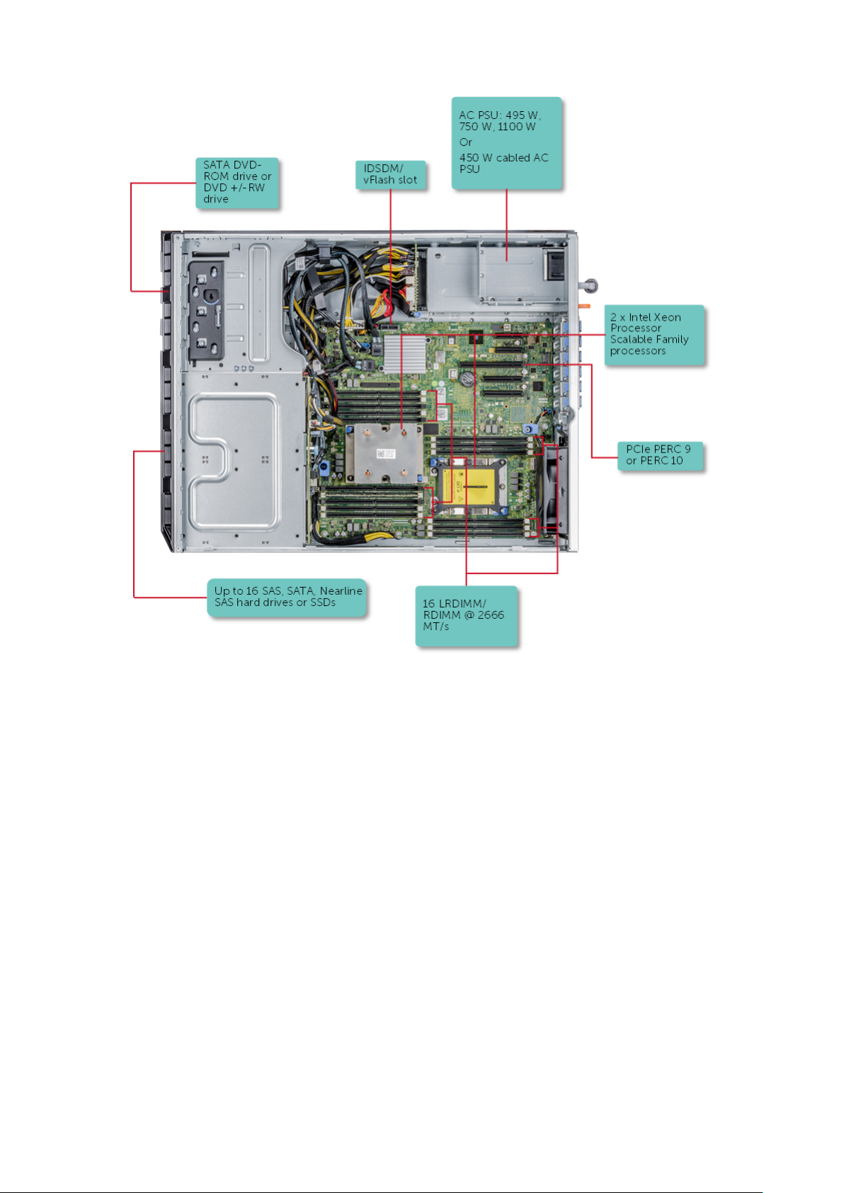
Figure 1. Supported configurations for a Dell EMC PowerEdge T440 system
8
Dell EMC PowerEdge T440 system overview
Front view of the system
The front view displays the features available on the front of the system.
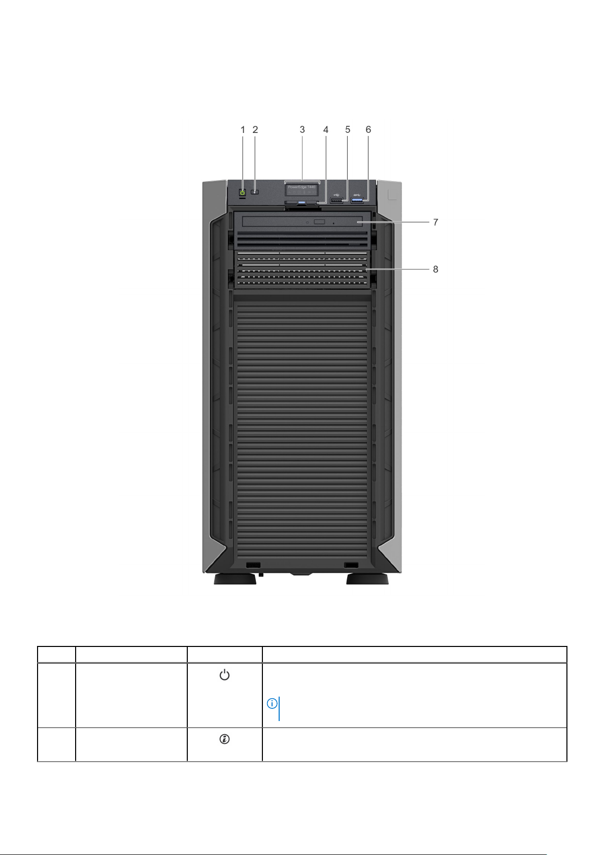
Figure 2. Front panel view of 4 x 3.5-inch cabled drive system
Table 1. Front panel features (continued)
Item Components Icon Description
1 Power button
2 System identification
button
Indicates if the system is powered on or off. Press the power button to
manually power on or off the system.
NOTE: Press the power button to gracefully shut down an ACPI-
compliant operating system.
The System Identification (ID) button is available on the front and back
of the systems. Press the button to identify a system in a rack by
Dell EMC PowerEdge T440 system overview 9

Table 1. Front panel features
Item Components Icon Description
turning on the system ID button. You can also use the system ID button
to reset iDRAC and to access BIOS using the step through mode.
3 Status LED indicator
panel
4 Information tag N/A
5 USB port 2.0 The USB ports are 4-pin, 2.0-compliant. These ports enable you to
6 USB port 3.0 The USB port is USB 3.0 compliant.
7 Optical drive bay N/A Enable you to install drives that are supported on your system.
8 Drive slot N/A Enables you to install TBUs for 8x and 16x backplane configurations, or
N/A
Indicate the status of the system. For more information, see the
Dell EMC PowerEdge T440 Technical Specifications on the product
documentation page.
The Information tag is a slide-out label panel that contains system
information such as Service Tag, NIC, MAC address, and so on. If you
have opted for the secure default access to iDRAC, the Information tag
also contains the iDRAC secure default password.
connect USB devices to the system.
For more information, see the Dell EMC PowerEdge T440 Technical
Specifications on the product documentation page.
drive blank in the empty drive slot to maintain proper system cooling.
10 Dell EMC PowerEdge T440 system overview
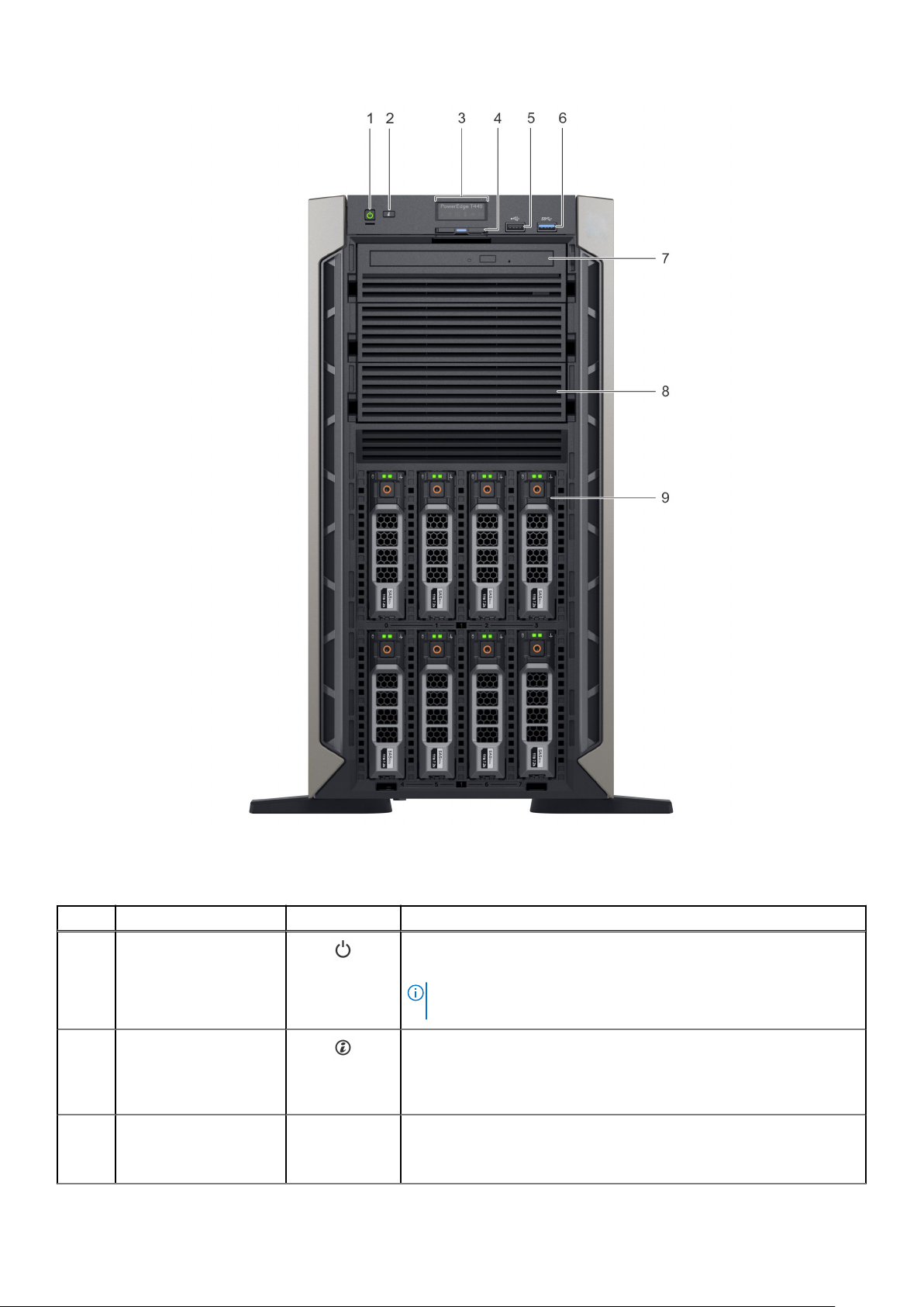
Figure 3. Front panel view of 8 x 3.5-inch hot swappable drive system
Table 2. Front panel features
Item Components Icon Description
1 Power button
2 System identification
button
3 Status LED indicator
panel
N/A
Indicates if the system is powered on or off. Press the power button to
manually power on or off the system.
NOTE: Press the power button to gracefully shut down an ACPI-
compliant operating system.
The System Identification (ID) button is available on the front and back
of the systems. Press the button to identify a system in a rack by
turning on the system ID button. You can also use the system ID button
to reset iDRAC and to access BIOS using the step through mode.
Indicate the status of the system. For more information, see the
Dell EMC PowerEdge T440 Technical Specifications on the product
documentation page.
Dell EMC PowerEdge T440 system overview 11
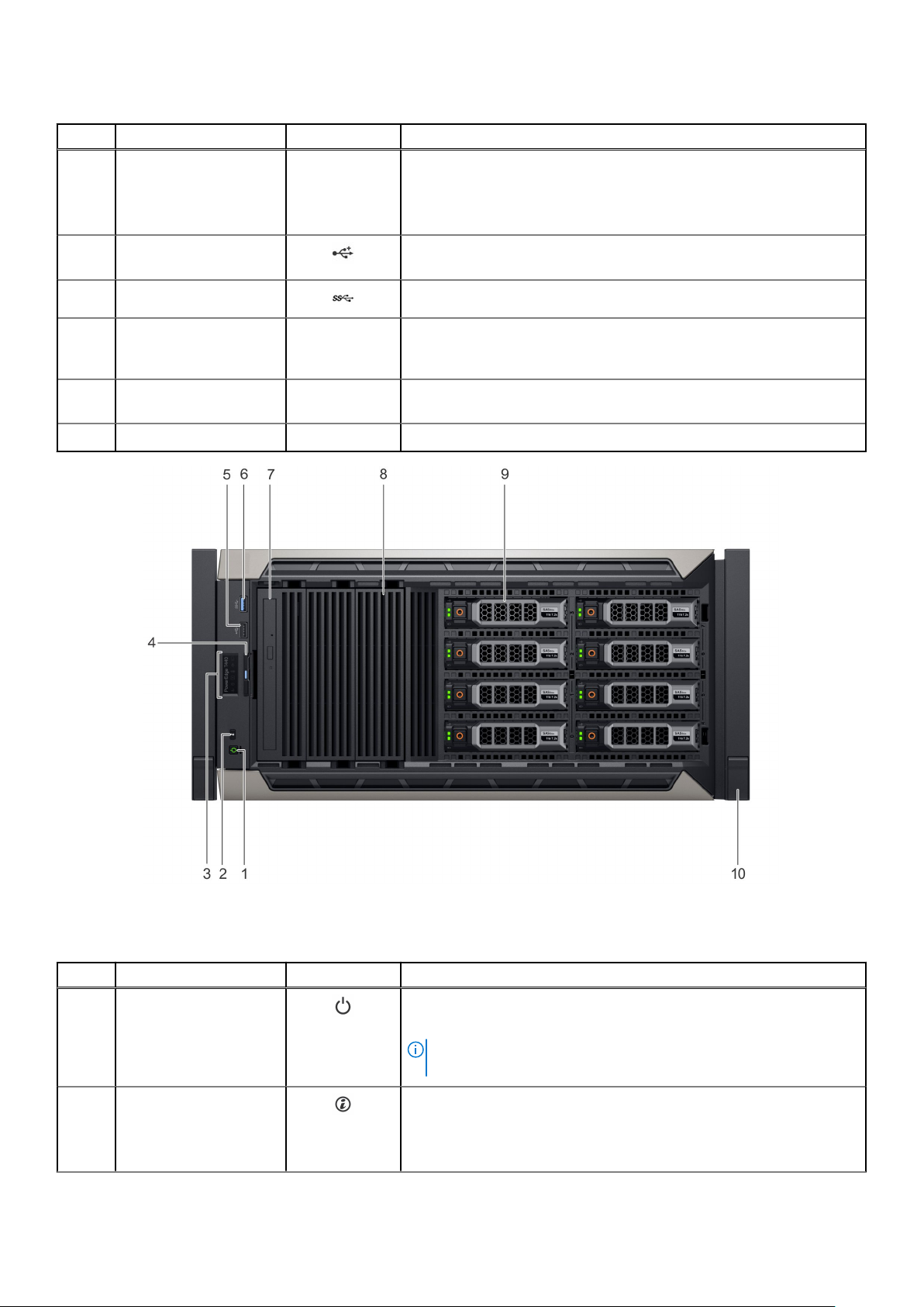
Table 2. Front panel features
Item Components Icon Description
4 Information tag N/A
5 USB port 2.0 The USB ports are 4-pin, 2.0-compliant. These ports enable you to
6 USB port 3.0 The USB port is USB 3.0 compliant.
7 Optical drive bay N/A Enable you to install drives that are supported on your system.
8 Drive slot N/A Enables you to install TBUs for 8x and 16x backplane configurations, or
9 Physical drives N/A 3.5-inch drives and 2.5-inch drives/SSDs.
The Information tag is a slide-out label panel that contains system
information such as Service Tag, NIC, MAC address, and so on. If you
have opted for the secure default access to iDRAC, the Information tag
also contains the iDRAC secure default password.
connect USB devices to the system.
For more information, see the Dell EMC PowerEdge T440 Technical
Specifications on the product documentation page.
drive blank in the empty drive slot to maintain proper system cooling.
Figure 4. Front panel view of 8 x 3.5-inch hot swappable drive system in rack mode
Table 3. Front panel features
Item Components Icon Description
1 Power button
2 System identification
button
12 Dell EMC PowerEdge T440 system overview
Indicates if the system is powered on or off. Press the power button to
manually power on or off the system.
NOTE: Press the power button to gracefully shut down an ACPI-
compliant operating system.
The System Identification (ID) button is available on the front and back
of the systems. Press the button to identify a system in a rack by
turning on the system ID button. You can also use the system ID button
to reset iDRAC and to access BIOS using the step through mode.

Table 3. Front panel features
Item Components Icon Description
3 Status LED indicator
panel
4 Information tag N/A
5 USB port 2.0 The USB ports are 4-pin, 2.0-compliant. These ports enable you to
6 USB port 3.0 The USB port is USB 3.0 compliant.
7 Optical drive bay N/A Enable you to install drives that are supported on your system.
8 Drive slot N/A Enables you to install TBUs for 8x and 16x backplane configurations, or
9 Physical drives N/A 3.5-inch drives and 2.5-inch drives/SSDs.
10 Rack ear N/A Enables you to convert the tower system to a rack system.
N/A
Indicate the status of the system. For more information, see the
Dell EMC PowerEdge T440 Technical Specifications on the product
documentation page.
The Information tag is a slide-out label panel that contains system
information such as Service Tag, NIC, MAC address, and so on. If you
have opted for the secure default access to iDRAC, the Information tag
also contains the iDRAC secure default password.
connect USB devices to the system.
For more information, see the Dell EMC PowerEdge T440 Technical
Specifications on the product documentation page.
drive blank in the empty drive slot to maintain proper system cooling.
Dell EMC PowerEdge T440 system overview 13
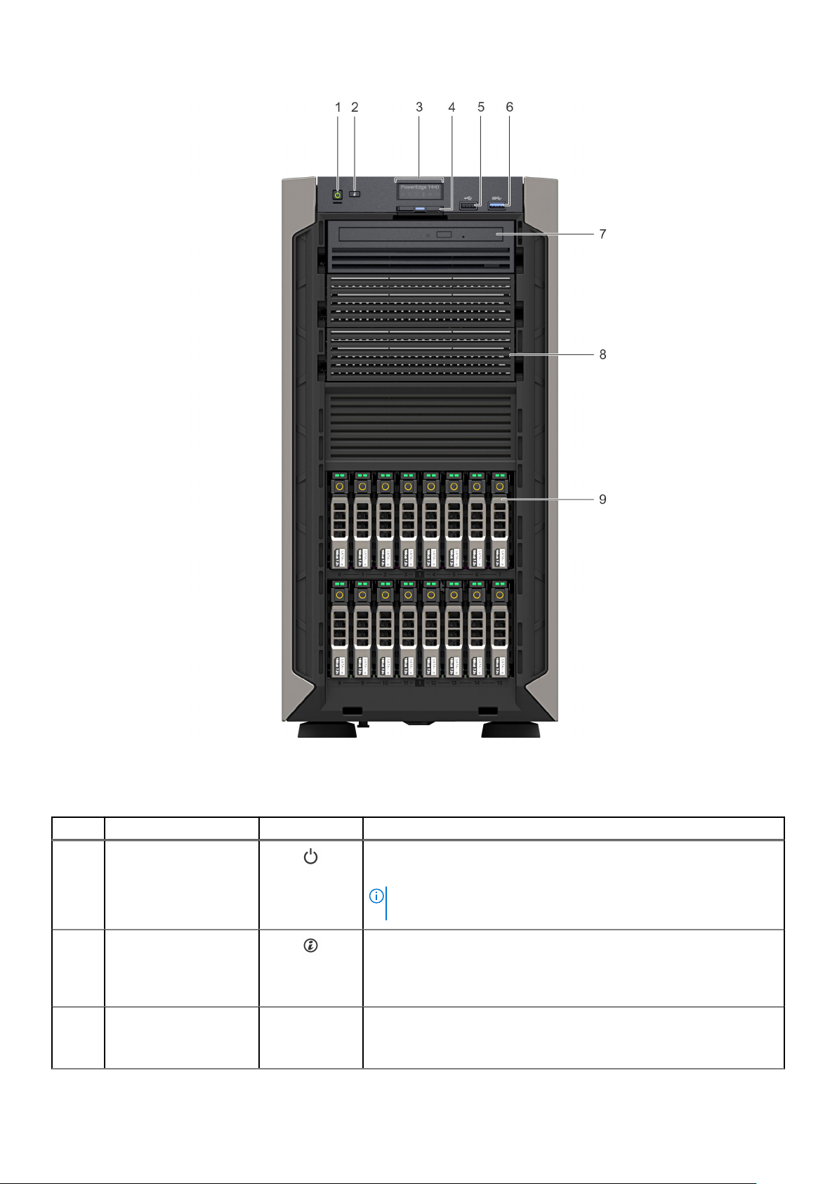
Figure 5. Front panel view of 16 x 2.5-inch hot swappable drive system
Table 4. Front panel features
Item Components Icon Description
1 Power button
2 System identification
button
3 Status LED indicator
panel
14 Dell EMC PowerEdge T440 system overview
N/A
Indicates if the system is powered on or off. Press the power button to
manually power on or off the system.
NOTE: Press the power button to gracefully shut down an ACPI-
compliant operating system.
The System Identification (ID) button is available on the front and back
of the systems. Press the button to identify a system in a rack by
turning on the system ID button. You can also use the system ID button
to reset iDRAC and to access BIOS using the step through mode.
Indicate the status of the system. For more information, see the
Dell EMC PowerEdge T440 Technical Specifications on the product
documentation page.
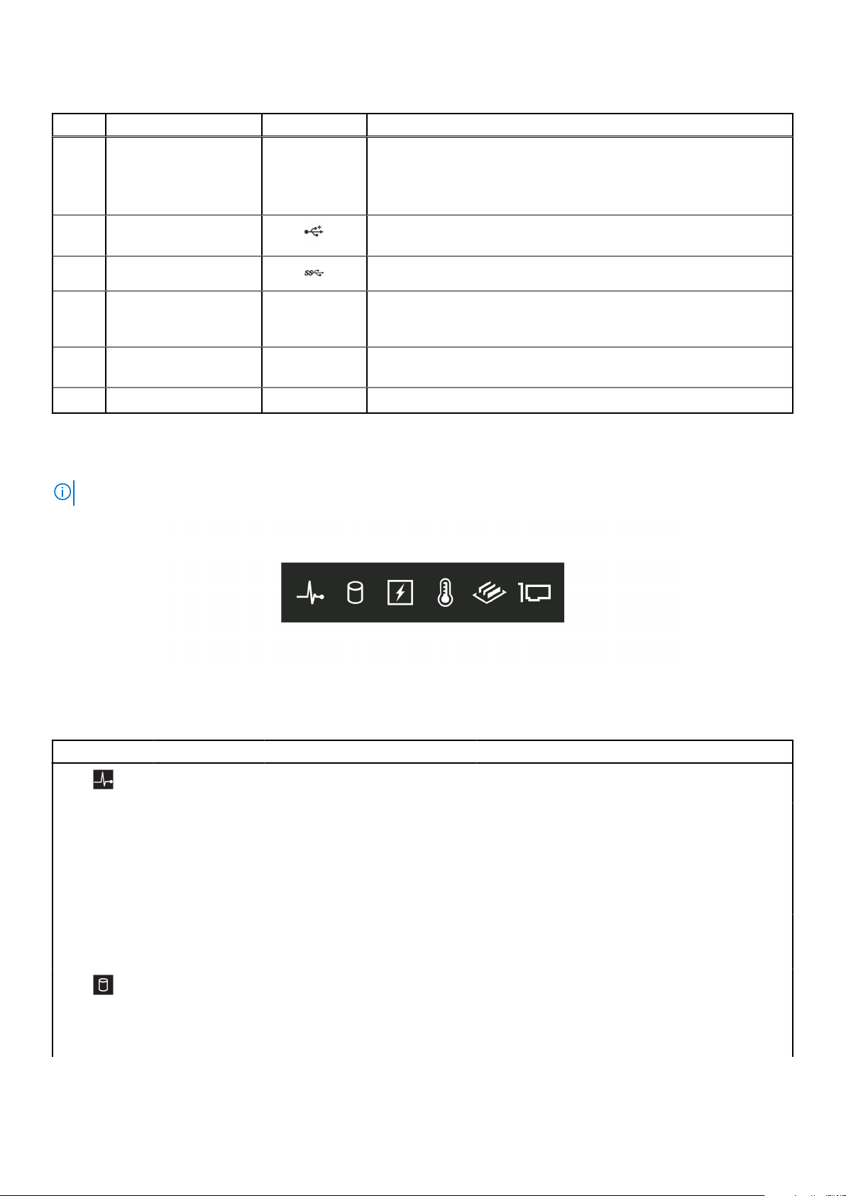
Table 4. Front panel features
Item Components Icon Description
4 Information tag N/A
5 USB port 2.0 The USB ports are 4-pin, 2.0-compliant. These ports enable you to
6 USB port 3.0 The USB port is USB 3.0 compliant.
7 Optical drive bay N/A Enable you to install drives that are supported on your system.
8 Drive slot N/A Enables you to install TBUs for 8x and 16x backplane configurations, or
9 Physical drives N/A 3.5-inch drives and 2.5-inch drives/SSDs.
The Information tag is a slide-out label panel that contains system
information such as Service Tag, NIC, MAC address, and so on. If you
have opted for the secure default access to iDRAC, the Information tag
also contains the iDRAC secure default password.
connect USB devices to the system.
For more information, see the Dell EMC PowerEdge T440 Technical
Specifications on the product documentation page.
drive blank in the empty drive slot to maintain proper system cooling.
Status LED indicators
NOTE: The indicators display solid amber if any error occurs.
Figure 6. Status LED indicators
Table 5. Status LED indicators and descriptions (continued)
Icon Description Condition Corrective action
Health indicator The indicator turns solid blue if the
system is in good health.
The indicator blinks amber, when
the system is:
● Powered on
● In standby
● In any error condition For
example, a failed fan, PSU, or
a drive
Drive indicator The indicator turns solid amber if
there is a drive error.
None required.
Check the System event log or system messages for
the specific issue.
For more information about error messages, see
the Event and Error Message Reference Guide for
14th Generation Dell EMC PowerEdge Servers at
www.dell.com/qrl.
The POST process is interrupted without any video
output due to invalid memory configurations. See
Getting help.
● Check the System event log to determine if the
drive has an error.
● Run the appropriate Online Diagnostics test.
Restart the system, and run embedded
diagnostics (ePSA.
Dell EMC PowerEdge T440 system overview 15
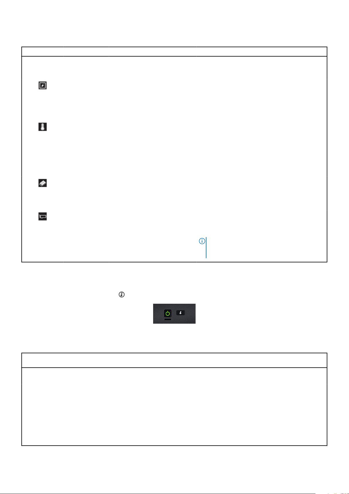
Table 5. Status LED indicators and descriptions
Icon Description Condition Corrective action
● If the drives are configured in a RAID array,
restart the system, and enter the host adapter
configuration utility.
Electrical
indicator
Temperature
indicator
The indicator turns solid amber
if the system experiences an
electrical error. For example,
voltage out of range, or a failed
power supply unit (PSU) or voltage
regulator.
The indicator turns solid amber if
the system experiences a thermal
error. For example, the ambient
temperature is out of range or
there is a fan failure.
Check the System event log or system messages for
the specific issue. If it is due to a problem with the
PSU, check the LED on the PSU. Reseat the PSU.
If the problem persists, see Getting help.
Ensure that none of the following conditions exist:
● A cooling fan has been uninstalled or has failed.
● System cover, air shroud, or back filler bracket is
uninstalled.
● Ambient temperature is too high.
● External airflow is obstructed.
If the problem persists, see Getting help.
Memory indicator The indicator turns solid amber if a
memory error occurs.
PCIe indicator The indicator turns solid amber if a
PCIe card experiences an error.
Check the System event log or system messages
for the location of the failed memory. Reseat the
memory module.
If the problem persists, see Getting help.
Restart the system. Update any required drivers for
the PCIe card. Reinstall the card.
If the problem persists, see Getting help.
NOTE: For more information about the
supported PCIe cards, see Expansion card
installation guidelines.
System health and system ID indicator codes
The system health and system ID button
Figure 7. System health and system ID buttons
Table 6. System health and system ID indicator codes
is on the front panel of your system.
System health and system ID
indicator code
Solid blue Indicates that the system is turned on, system is healthy, and system ID mode is not
Blinking blue Indicates that the system ID mode is active. Press the system health and system ID
Solid amber Indicates that the system is in fail-safe mode. If the problem persists, see Getting
Blinking amber Indicates that the system is experiencing a fault. Check the System Event Log
16 Dell EMC PowerEdge T440 system overview
Condition
active. Press the system health and system ID button to switch to system ID mode.
button to switch to system health mode.
help.
for specific error messages. For information about the event and error messages
generated by the system firmware and agents that monitor system components, go to
qrl.dell.com > Look Up > Error Code, type the error code, and then click Look it up.
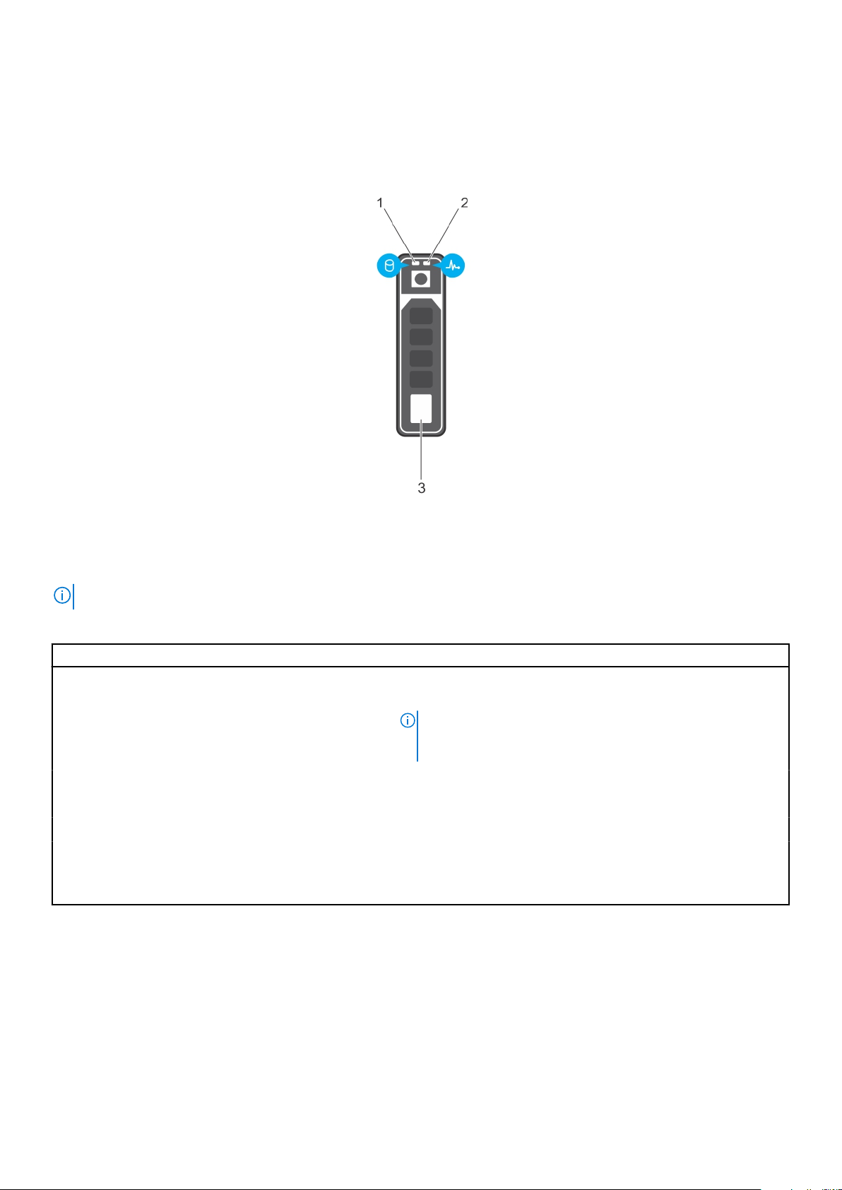
Drive indicator codes
Each drive carrier has an activity LED indicator and a status LED indicator. The indicators provide information about the status
of the drive. The activity LED indicator indicates whether the drive is in use or not. The status LED indicator indicates the power
condition of the drive.
Figure 8. Drive indicators
1. Drive activity LED indicator
2. Drive status LED indicator
3. Drive capacity label
NOTE: If the drive is in the Advanced Host Controller Interface (AHCI) mode, the status LED indicator does not turn on.
Table 7. Drive indicator codes
Drive status indicator code Condition
Flashes green twice per second Identifying drive or preparing for removal.
Off Drive ready for removal.
NOTE: The drive status indicator remains off until all drives are
initialized after the system is turned on. Drives are not ready
for removal during this time.
Flashes green, amber, and then powers off Predicted drive failure.
Flashes amber 4 times per second Drive failed.
Flashes green slowly Drive rebuilding.
Solid green Drive online.
Flashes green for three seconds, amber for three
seconds, and then turns off after six seconds.
Rebuild stopped.
Back view of the system
The back panel view of the system shows the features available on the back of the server, such as the system identification
button, power supply sockets, iDRAC storage media, NIC ports, and USB and VGA ports. Most of the expansion card ports can
be accessed from the back panel. The hot swappable and cabled power supply units are accessible from the back panel.
Dell EMC PowerEdge T440 system overview
17
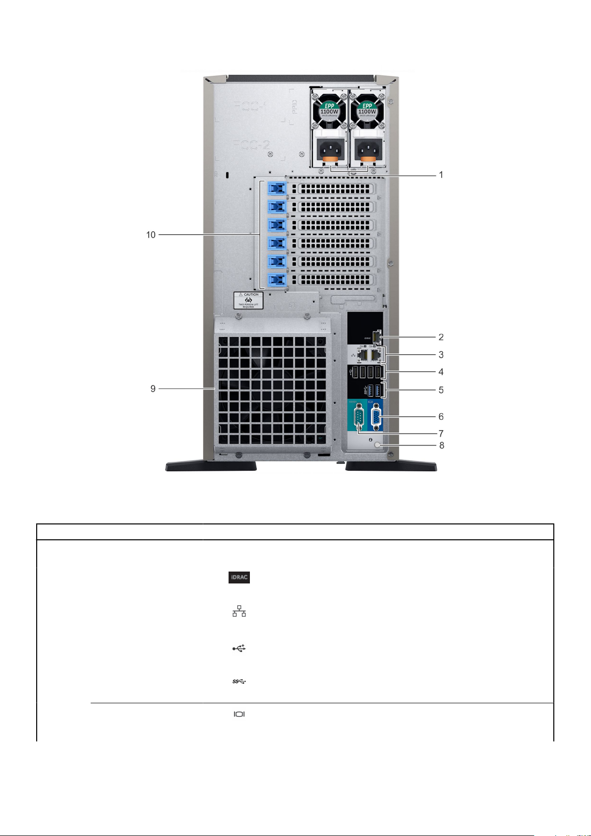
Figure 9. Back view of the system with optional redundant cooling fan
Table 8. Features available on the back view
Item Ports, panels, or slots Icon Description
1 Power supply unit (2) N/A For more information, see the Dell EMC PowerEdge T440 Technical
Specifications on the product documentation page.
2 iDRAC9 dedicated
network port
3 NIC port (2) The NIC ports are integrated on the system board provide network
4 USB 2.0 port (4)
Enables you to remotely access iDRAC. For more information, see
the iDRAC User’s Guide at www.dell.com/poweredgemanuals.
connectivity. For more information, see the Dell EMC PowerEdge
T440 Technical Specifications on the product documentation page.
The USB ports are 4-pin, 2.0-compliant. These ports enable you to
connect USB devices to the system.
5 USB 3.0 port (2)
6
18 Dell EMC PowerEdge T440 system overview
VGA port Enables you to connect a display device to the system. For
The USB ports are 9-pin and 3.0-compliant. These ports enable you
to connect USB devices to the system.
more information, see the Dell EMC PowerEdge T440 Technical
Specifications on the product documentation page.
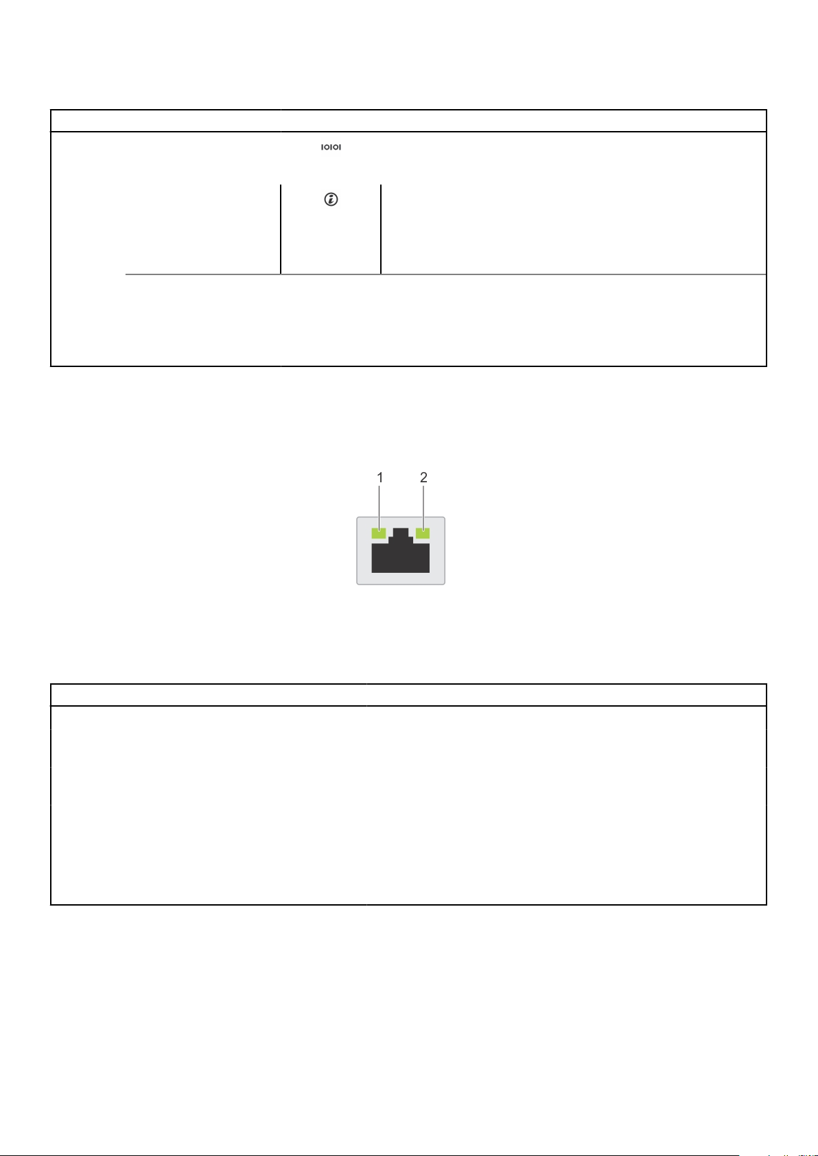
Table 8. Features available on the back view
Item Ports, panels, or slots Icon Description
7 Serial port Enables you to connect a serial device to the system. For
more information, see the Dell EMC PowerEdge T440 Technical
Specifications on the product documentation page.
8 System identification
button
The System Identification (ID) button is available on the front and
back of the systems. Press the button to identify a system in a
rack by turning on the system ID button. You can also use the
system ID button to reset iDRAC and to access BIOS using the
step through mode.
9
10 PCIe expansion card
External cooling fan
(optional)
slot(6)
N/A Enables you to connect an optional redundant cooling fan.
N/A The expansion slots enable you to connect PCI Express expansion
cards. For more information, see the Dell EMC PowerEdge T440
Technical Specifications on the product documentation page.
NIC indicator codes
Each NIC on the back of the system has indicators that provide information about the activity and link status. The activity LED
indicator indicates if data is flowing through the NIC, and the link LED indicator indicates the speed of the connected network.
Figure 10. NIC indicator codes
1. Link LED indicator
2. Activity LED indicator
Table 9. NIC indicator codes
Status Condition
Link and activity indicators are off. The NIC is not connected to the network.
Link indicator is green, and activity indicator is blinking
green.
Link indicator is amber, and activity indicator is blinking
green.
Link indicator is green, and activity indicator is off. The NIC is connected to a valid network at its maximum port speed,
Link indicator is amber, and activity indicator is off. The NIC is connected to a valid network at less than its maximum
Link indicator is blinking green, and activity is off. NIC identify is enabled through the NIC configuration utility.
The NIC is connected to a valid network at its maximum port speed,
and data is being sent or received.
The NIC is connected to a valid network at less than its maximum
port speed, and data is being sent or received.
and data is not being sent or received.
port speed, and data is not being sent or received.
Power supply unit indicator codes
AC power supply units (PSUs) have an illuminated translucent handle that serves as an indicator. The indicator shows whether
power is present or if a power fault has occurred.
Dell EMC PowerEdge T440 system overview
19

Figure 11. AC PSU status indicator
1. AC PSU status indicator/handle
Table 10. AC PSU status indicator codes
Power indicator codes Condition
Green A valid power source is connected to the PSU, and the PSU is operational.
Blinking amber Indicates a problem with the PSU.
Not illuminated Power is not connected to the PSU.
Blinking green When the firmware of the PSU is being updated, the PSU handle blinks green.
CAUTION: Do not disconnect the power cord, or unplug the PSU when updating
firmware. If firmware update is interrupted, the PSUs do not function.
Blinking green and turns
off
When hot-plugging a PSU, the PSU handle blinks green five times at a rate of 4 Hz and powers off.
It indicates a PSU mismatch regarding efficiency, feature set, health status, or supported voltage.
CAUTION: If two PSUs are installed, both the PSUs must have the same type of label;
for example, Extended Power Performance (EPP) label. Mixing PSUs from previous
generations of PowerEdge servers is not supported, even if the PSUs have the same
power rating. It results in a PSU mismatch condition or failure to power on the
system.
CAUTION: When correcting a PSU mismatch, replace only the PSU with the blinking
indicator. Swapping the PSU to make a matched pair can result in an error condition
and unexpected system shutdown. To change from a high output configuration to a
low output configuration or conversely, you must turn off the system.
CAUTION: AC PSUs support both 240 V and 120 V input voltages except for Titanium
PSUs, which support only 240 V. When two identical PSUs receive different input
voltages, they can output different wattages, and trigger a mismatch.
CAUTION: If two PSUs are used, they must be of the same type and have the same
maximum output power.
Locating the Service Tag of your system
You can identify your system using the unique Express Service Code and Service Tag. Pull out the information tag in front of the
system to view the Express Service Code and Service Tag. Alternatively, the information may be on a sticker on the chassis of
the system. The mini Enterprise Service Tag (EST) is found on the back of the system. This information is used by Dell to route
support calls to the appropriate personnel.
20
Dell EMC PowerEdge T440 system overview
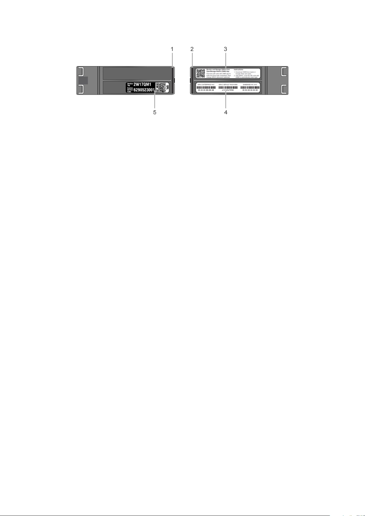
Figure 12. Locating Service Tag of your system
1. Information tag (top view) 2. Information tag (back view)
3. OpenManage Mobile (OMM) label 4. iDRAC MAC address and iDRAC secure password label
5. Service Tag
Dell EMC PowerEdge T440 system overview 21
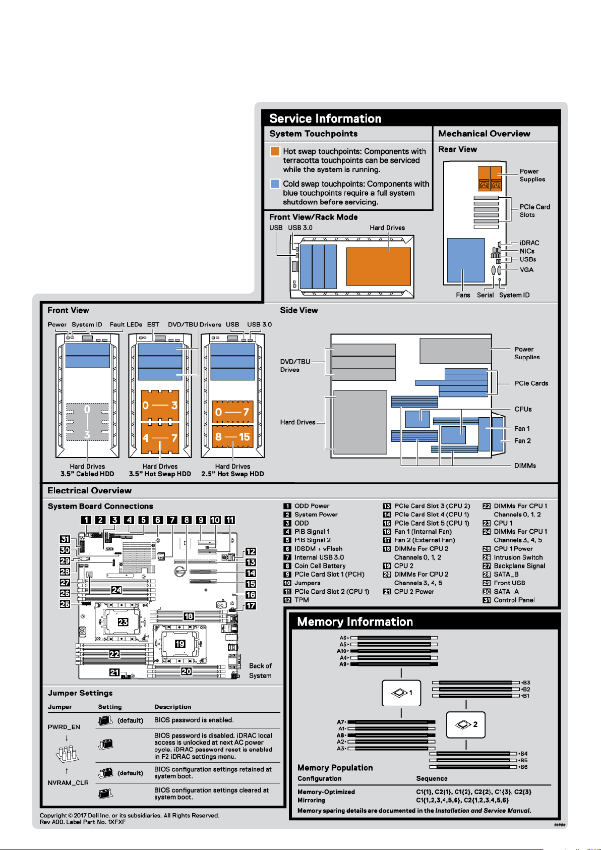
System information label
22
Figure 13. PowerEdge T440 – Service information
Dell EMC PowerEdge T440 system overview
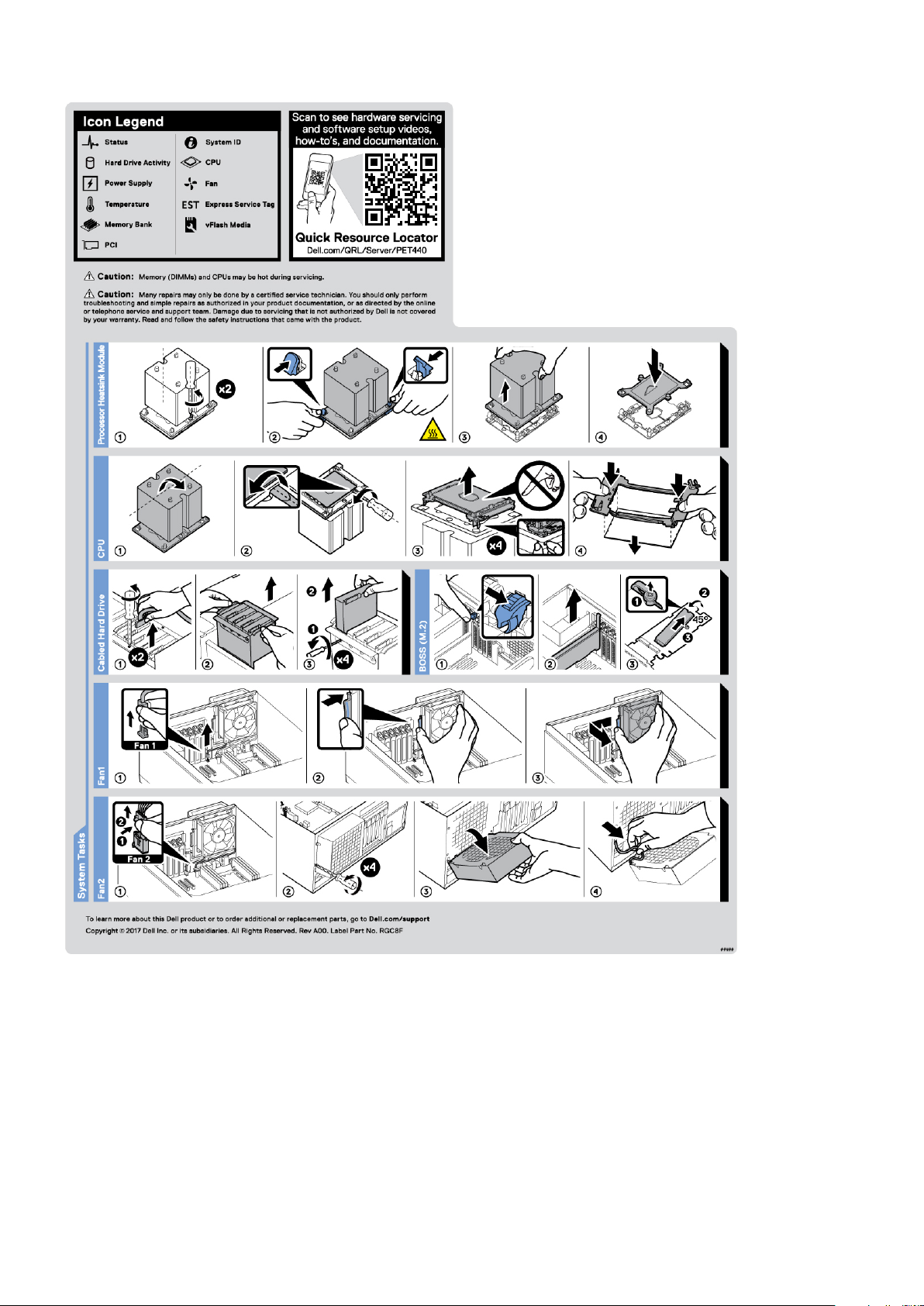
Figure 14. PowerEdge T440 – Service information
Dell EMC PowerEdge T440 system overview
23

2
Initial system setup and configuration
Topics:
• Setting up your system
iDRAC configuration
•
• Options to install the operating system
Setting up your system
Perform the following steps to set up your system:
Steps
1. Unpack the system.
2. Install the system into the rack. For more information about installing the system into the rack, see the Rail Installation Guide
at www.dell.com/poweredgemanuals.
3. Connect the peripherals to the system.
4. Connect the system to its electrical outlet.
5. Power on the system by pressing the power button or by using iDRAC.
6. Power on the attached peripherals.
For more information about setting up your system, see the Getting Started Guide that shipped with your system.
iDRAC configuration
The Integrated Dell Remote Access Controller (iDRAC) is designed to make system administrators more productive and improve
the overall availability of Dell systems. iDRAC alerts administrators about system issues and enables them to perform remote
system management. This reduces the need for physical access to the system.
Options to set up iDRAC IP address
To enable communication between your system and iDRAC, you must first configure the network settings based on your
network infrastructure.
NOTE: For static IP configuration, you must request for it at the time of purchase.
This option is set to DHCP by Default. You can set up the IP address by using one of the following interfaces:
Interfaces
iDRAC Settings
utility
Dell Deployment
Toolkit
Dell Lifecycle
Controller
NOTE: To access iDRAC, ensure that you connect the ethernet cable to the iDRAC9 dedicated network port. You can also
access iDRAC through the shared LOM mode, if you have opted for a system that has the shared LOM mode enabled.
Document/Section
Dell Integrated Dell Remote Access Controller User's Guide at www.dell.com/poweredgemanuals
Dell Deployment Toolkit User’s Guide at www.dell.com/openmanagemanuals > OpenManage Deployment
Toolkit
Dell Lifecycle Controller User’s Guide at www.dell.com/poweredgemanuals
24 Initial system setup and configuration

Log in to iDRAC
You can log in to iDRAC as:
● iDRAC user
● Microsoft Active Directory user
● Lightweight Directory Access Protocol (LDAP) user
If you have opted for secure default access to iDRAC, you must use the iDRAC secure default password available on the system
Information tag. If you have not opted for secure default access to iDRAC, then use the default user name and password –root
and ca lvi n. You can also log in by using your Single Sign-On or Smart Card.
NOTE: You must have the iDRAC credentials to log in to iDRAC.
NOTE: Ensure that you change the default username and password after setting up the iDRAC IP address.
For more information about logging in to the iDRAC and iDRAC licenses, see the latest Integrated Dell Remote Access Controller
User's Guide at www.dell.com/poweredgemanuals.
You can also access iDRAC by using RACADM. For more information, see the RACADM Command Line Interface Reference
Guide at www.dell.com/poweredgemanuals.
Options to install the operating system
If the system is shipped without an operating system, install a supported operating system by using one of the following
resources:
Table 11. Resources to install the operating system
Resources Location
iDRAC www.dell.com/idracmanuals
Lifecycle Controller www.dell.com/idracmanuals > Lifecycle Controller
OpenManage Deployment Toolkit www.dell.com/openmanagemanuals > OpenManage
Deployment Toolkit
Dell certified VMware ESXi www.dell.com/virtualizationsolutions
Installation and How-to videos for supported operating
systems on PowerEdge systems
Supported Operating Systems for Dell EMC PowerEdge
systems
Methods to download firmware and drivers
You can download the firmware and drivers by using any of the following methods:
Table 12. Firmware and drivers
Methods Location
From the Dell EMC support site www.dell.com/support/home
Using Dell Remote Access Controller Lifecycle Controller
(iDRAC with LC)
www.dell.com/idracmanuals
Using Dell Repository Manager (DRM) www.dell.com/openmanagemanuals > Repository Manager
Using Dell OpenManage Essentials www.dell.com/openmanagemanuals > OpenManage Essentials
Using Dell OpenManage Enterprise www.dell.com/openmanagemanuals > OpenManage
Enterprise
Using Dell Server Update Utility (SUU) www.dell.com/openmanagemanuals > Server Update Utility
Initial system setup and configuration 25

Table 12. Firmware and drivers
Methods Location
Using Dell OpenManage Deployment Toolkit (DTK) www.dell.com/openmanagemanuals > OpenManage
Deployment Toolkit
Using iDRAC virtual media www.dell.com/idracmanuals
Downloading drivers and firmware
Dell EMC recommends that you download and install the latest BIOS, drivers, and systems management firmware on your
system.
Prerequisites
Ensure that you clear the web browser cache before downloading the drivers and firmware.
Steps
1. Go to www.dell.com/support/home.
2. In the Drivers & Downloads section, type the Service Tag of your system in the Enter a Service Tag or product ID box,
and then click Submit.
NOTE: If you do not have the Service Tag, select Detect Product to allow the system to automatically detect the
Service Tag, or click View products, and navigate to your product.
3. Click Drivers & Downloads.
The drivers that are applicable to your system are displayed.
4. Download the drivers to a USB drive, CD, or DVD.
26
Initial system setup and configuration

Installing and removing system components
Topics:
• Safety instructions
Before working inside your system
•
• After working inside your system
• Recommended tools
• Optional front bezel
• System feet
• Inside the system
• Caster wheels – optional
• System cover
• Air shroud
• Drives
• Optical drives and tape drives
• Cabled drives
• Drive backplane
• System memory
• Cooling fans
• Optional internal USB memory key
• Expansion card holder
• Expansion cards
• M.2 SSD module
• Optional MicroSD or vFlash card
• Optional IDSDM or vFlash module
• Processors and heat sinks
• Power supply units
• Power interposer board
• System battery
• Control panel assembly
• System board
• Trusted Platform Module
• Converting the system from tower mode to rack mode
• Updating the system BIOS
3
Safety instructions
Whenever you need to lift the system, get others to assist you. To avoid injury, do not attempt to lift the system by
NOTE:
yourself.
WARNING: Opening or removing the system cover while the system is powered on may expose you to a risk of
electric shock.
CAUTION: Do not operate the system without the cover for a duration exceeding five minutes. Operating the
system without the system cover can result in component damage.
CAUTION: Many repairs may only be done by a certified service technician. You should only perform
troubleshooting and simple repairs as authorized in your product documentation, or as directed by the online or
telephone service and support team. Damage due to servicing that is not authorized by Dell is not covered by
your warranty. Read and follow the safety instructions that are shipped with your product.
Installing and removing system components 27

NOTE: It is recommended that you always use an antistatic mat and antistatic strap while working on components inside
the system.
CAUTION: To ensure proper operation and cooling, all bays in the system and system fans must be always
populated with a component or a blank.
Before working inside your system
Prerequisites
Follow the safety guidelines listed in Safety instructions.
Steps
1. Turn off the system, including all attached peripherals.
2. Disconnect the system from the electrical outlet and disconnect the peripherals.
3. Lay the system on its side.
4. Remove the system cover.
After working inside your system
Prerequisites
Follow the safety guidelines listed in Safety instructions.
Steps
1. Install the system cover.
2. Place the system upright on a flat, stable surface.
3. Reconnect the peripherals and connect the system to the electrical outlet.
4. Turn on the attached peripherals and then turn on the system.
Recommended tools
You need the following tools to perform the removal and installation procedures:
● Key to the bezel lock
The key is required only if your system includes a bezel.
● Phillips #1 screwdriver
● Phillips #2 screwdriver
● Torx #T30 screwdriver
● Wrist grounding strap
Optional front bezel
Removing the front bezel
Prerequisites
Follow the safety guidelines listed in Safety instructions.
Steps
1. Unlock the bezel by using the bezel key.
28
Installing and removing system components
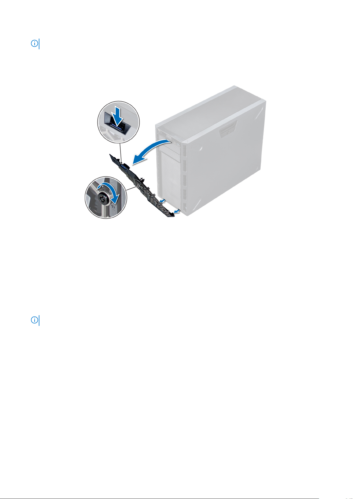
NOTE: There are two bezel keys attached to the back of the bezel.
2. Press the release latch at the top of the bezel.
3. Pull the top end of the bezel away from the system.
4. Unhook the bezel tabs from the slots at the bottom of the system, and pull the bezel away from the system.
Figure 15. Removing the front bezel
Installing the front bezel
Prerequisites
Follow the safety guidelines listed in Safety instructions.
Steps
1. Locate and remove the bezel key.
NOTE: There are two bezel keys attached to the back of the bezel.
2. Insert the bezel tabs into the slots in the chassis.
3. Press the release latch, and push the bezel toward the system until the bezel locks into place.
4. Using the key lock the bezel.
Installing and removing system components
29
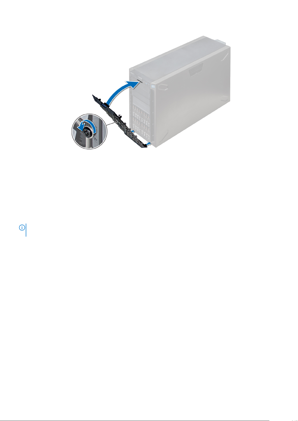
Figure 16. Installing the front bezel
System feet
Removing the system feet
Prerequisites
NOTE:
It is recommended that you remove the system feet only when you are converting the system from the tower mode
to the rack mode, or when you are replacing the system feet with the wheel assembly.
1. Follow the safety guidelines listed in Safety instructions.
2. Place the system on its side on a flat, stable surface.
3. Rotate the system feet inward.
Steps
Using the Phillips #2 screwdriver, remove the screw that secures the foot to the base of the system.
a. Repeat the above step for the 3 remaining feet.
30
Installing and removing system components
 Loading...