


Dell EMC PowerEdge T340
Technical Guide
Reg ula tor y M ode l: E60 S
Reg ula tor y T ype : E 60S 001
Dec . 2 020
Rev . A 07

Notes, cautions, and warnings
NOTE: A NOTE indicates important information that helps you make better use of your product.
CAUTION: A CAUTION indicates either potential damage to hardware or loss of data and tells you how to avoid
the problem.
WARNING: A WARNING indicates a potential for property damage, personal injury, or death.
© 2018 - 2020 Dell Inc. or its subsidiaries. All rights reserved . D ell , E MC, and other trademarks are trademarks of Dell Inc. or its subsidi ari es.
Other trademarks may be trademarks of their respective owners.

Product Overview
Topics:
• Introduction
New technologies
•
Introduction
The Dell EMC PowerEdge T340 is the reliable, easy to manage, and scalable 1-socket tower server for growing businesses and
remote offices/ branch offices.
New technologies
The PowerEdge T340 equipped with Intel® Xeon® E-2100 and E-2200 product family processors support to help run
applications faster and support for full-feature remote management (iDRAC9).
The T340 is versatile enough to address many customer segments and workloads. Target workloads include
● Small and medium businesses and organizations: Collaboration/sharing productivity applications, databases, web serving,
backup/recovery, and mail and messaging.
1
● ROBO: Applications and workloads specific to the particular industry, e.g. Retail, Healthcare, Finance, Education, etc.
The following table shows the list of new technologies offered by the PowerEdge T340:
New Technologies
Intel® C246 series chipset Please refer to the chipset section for details.
Intel® Xeon® processor E- 2100 and E-2200 Product
Family
Next Generation SW RAID, PERC S140 The new 1-socket servers support the latest S140 software
iDRAC 9 The new embedded system management solution for Dell
Detailed Descriptions
The Intel® processor that works with Intel® C246 series
chipset. The Xeon® E-2100 and E-2200 processors have
increased core count and embedded PCIe lanes that will
improve the IO performance and a lot more features. Please
refer to section 8, Processors for details.
RAID along with H330 and H730P controller cards with
improved functionality and faster performance. New SW RAID
supports RAID 0, 1, 5 and 10.
EMC server features hardware and firmware inventory and
alerting, in depth memory alerting, faster performance,
dedicated gigabit port, email alerts, electronic licensing,
editable user work notes log and more. Dedicated iDRAC
Direct microUSB port improves at-the-box management.
Product Overview 3

Product features
Topics:
• Product comparison
Product specifications
•
Product comparison
The following table shows the comparison between the PowerEdge T330 and PowerEdge T340:
Table 1. Product comparison with predecessor
Feature PowerEdge T330 PowerEdge T340
2
Processor
Front Side Bus DMI 3.0 DMI 3.0
Number of
processors
Number or cores
L2/L3 cache
Chipset
Memory Module
Hard drive bays
● Intel® Xeon® E3-1200 v6 Processor family
● Intel® Pentium®
● Intel® Celeron®
● Intel® Core™ i3®
● 1 ● 1
● Up to 4 cores ● Up to 8 cores
● 2.0 MB per core
● 4 MB or 8 MB
● Intel® C236 ● Intel® C246
● DDR4: 4 UDIMMs with ECC
● Speed: Up to 2400MT/s
● Min RAM: 4 GB
● Max RAM: 64 GB
● 8 x 3.5-inch hot plug
● 8 x 2.5-inch hot plug (in 3.5-inch carrier)
● Intel® Xeon® E-2100 and E-2200 Processor
family
● Intel® Pentium®
● Intel® Celeron®
● Intel® Core™ i3®
● 2.0 MB per core
● 8 MB or 12 MB
● DDR4: 4 UDIMMs with ECC
● Speed: Up to 2666MT/s
● Min RAM: 8GB
● Max RAM: 64 GB
● 8 x 3.5-inch hot plug
● 8 x 2.5-inch hot plug (in 3.5-inch carrier)
Hard drive types
External hard drive
bays
RAID controllers
4 Product features
● 2.5-inch SATA 7.2K HDDs
● 2.5-inch Near Line SAS 7.2K HDDs
● 2.5-inch SAS 10K HDDs
● 2.5-inch SAS 15K HDDs
● 3.5-inch Enterprise SATA 7.2K HDDs
● 3.5-inch Near Line SAS 7.2K HDDs
● 2.5-inch SATA SSDs
● 3 x 5.25-inch bay ● 3 x 5.25-inch bay
● Chipset based SATA, PERC S130
● Non RAID controller: 12GB SAS HBA
● 2.5-inch SATA 7.2K HDDs
● 2.5-inch Near Line SAS 7.2K HDDs
● 2.5-inch SAS 10K HDDs
● 2.5-inch SAS 15K HDDs
● 3.5-inch Enterprise SATA 7.2K HDDs
● 3.5-inch Near Line SAS 7.2K HDDs
● 2.5-inch SATA SSDs
● Chipset based SATA, PERC S140

Table 1. Product comparison with predecessor (continued)
Feature PowerEdge T330 PowerEdge T340
● PERC H330
● PERC H730
● PERC H830
Boot optimized
storage subsytem
Server management
I/O slots
NIC/LOM
USB Rear I/O
● Not supported ● 2x M.2 240GB (RAID 1 or No RAID)
● Dell Open Manage featuring Dell
Management Console
● Lifecycle Controller 3.0
● iDRAC8 Enterprise
● 1 x 8 PCIe Gen3 (x16 connector) FH/HL
● 1 x 4 PCIe Gen3 (x8 connector) FH/HL
● 1 x 4 PCIe Gen3 (x8 connector) FH/HL
● 1 x 1 PCIe Gen3 (x1 connector) FH/HL
● 2 x 1GbE LOM ● 2 x 1GbE LOM
● 2 x USB3.0 + 4 x USB 2.0
Front I/O
● 1 x USB3.0 + 1 x USB 2.0
Internal
● 1 x Internal USB 3.0
● Non RAID controller: 12GB SAS HBA, PERC
HBA330
● PERC H330
● PERC H730P
● 1x M.2 240GB (No RAID only)
● Dell Open Manage featuring Dell Management
Console
● Lifecycle Controller 3.0
● iDRAC9 Enterprise
● 1 x 8 PCIe Gen3 (x16 connector) FH/HL
● 1 x 8 PCIe Gen3 (x8 connector) FH/HL
● 1 x 4 PCIe Gen3 (x8 connector) FH/HL
● 1 x 1 PCIe Gen3 (x1 connector) FH/HL
Rear I/O
● 2 x USB3.0 + 4 x USB 2.0
Front I/O
● 1 x USB3.0
● 1 x Micro USB 2.0 (dedicated iDRAC Direct)
Internal
● 1 x Internal USB 3.0
Power supplies
Fans
SD module
Dimensions (HxWxD)
Weight
● Single or Dual Redundant 495W power supply
or single 350W cabled power supply
● No Fan fault tolerance ● No Fan fault tolerance
● IDSDM ● IDSDM
● Height 16.94 inch / 43.0 cm
● Width 8.58 inch / 21.8 cm
● Height 23.8 inch / 60.5 cm
● Max 26 Kg ● Max 26 Kg
● Single or Dual Redundant 495W power supply or
● Height 16.94 inch / 43.0 cm
● Width 8.58 inch / 21.8 cm
● Height 23.7 inch / 60.3 cm
Product specifications
The following able list the technical specifications for the PowerEdge T340:
Table 2. Technical specifications
Features Specifications
Form Factor
Processors
● Tower Server
● Intel® Xeon® processor E-2100 and E-2200 product
family
single 350W cabled power supply
Product features 5

Table 2. Technical specifications (continued)
Features Specifications
● Intel® Core™ i3
● Intel® Pentium®
● Intel® Celeron
Processor sockets
Front Side Bus or HyperTransport
Cache
Chipset
Memory
I/O slots
RAID controller
Drive bays
Maximum internal storage
● 1
● DMI
● 2.0 MB per core
● 8 MB or 12 MB
● Intel C246 Chipset
● Up to 64GB (4 DIMM Slots)
● 8GB/16GB 2666MT/s Unbuffered with ECC only
● MIN/ MAX RAM: 8GB/64GB
● 4 GEN3 PCIe slots:
○ One x8 slot (with x16 Connector)
○ Two x4 slot(with x8 connector)
○ One x1 slot
● Internal controllers: PERC S140, PERC H330, H730P
● External HBAs (non-RAID): 12GB SAS HBA
● Up to 8 x 2.5-inch Hot-Plug drives( in 3.5-inch carrier)
● Up to 8 x 3.5-inch Hot-Plug drives
● 112TB for 8 HDD config
Hard drives
Embedded LOM/NIC
Communications Optional add-in cards:
● 2.5-inch SATA 7.2K HDDs
● 2.5-inch Near Line SAS 7.2K HDDs
● 2.5-inch SAS 10K HDDs
● 2.5-inch SAS 15K HDDs
● 3.5-inch Enterprise SATA 7.2K HDDs
● 3.5-inch Near Line SAS 7.2K HDDs
● 2.5-inch SATA SSDs
● 2.5-inch SAS SSDs
HDDs capacities:
300GB, 600GB, 900GB, 1TB, 1.2TB, 1.8TB, 2TB, 2.4TB, 4TB,
6TB, 8TB, 10TB, 12TB, 14TB
SSD capacities:
240GB, 480GB, 960GB, 1.2TB, 1.6TB, 1.92TB, 3.84TB, and
7.68TB
● Integrated BROADCOM BCM5720 Gigabit Ethernet
Controller
● 10GbE Intel (Dual) Sageville Sage Pond Dual port 10Gb
Base-T adapter – FH
● 10GbE Intel (Dual) Fortville Eagle Fountain Dual port 10Gb
SFP+ adapter – FH
6 Product features

Table 2. Technical specifications (continued)
Features Specifications
● 1GbE Intel (Dual) Powerville Troi-Stony Dual port 1Gb
Base-T adapter – FH
● 1GbE Intel (Quad) Powerville Lore-Stony Quad port 1Gb
Base-T adapter – FH
● 1GbE Broadcom (Dual) 5720 Bashir Dual port 1Gb Base-T
adapter – FH
● 1GbE Broadcom (Quad) 5719 Cardassia Quad port 1Gb
Base-T adapter – FH
● FC8 Emulex (Dual) Saturn Wildfire Dual port FC8 SFP+
adapter – FH
Power supply
Availability
Video
Remote management
Systems management
Featured database applications
● 350W cable PSU auto sensing
● Hot Plug RDNT Common PSU 495W
● TPM/No TPM
● Cluster support
● ECC memory, UDIMM
● Hot-plug hard drives, redundant power
● Internal Dual SD Module(IDSDM)
● Integrated Matrox G200 with iDRAC9
● Base Management Console
● iDRAC9 Express
● iDRAC9 Enterprise
● Dell Open Manage featuring Dell Management Console
● Lifecycle Controller 3.0
● iDRAC9 Enterprise
● Microsoft® SQL Server® solutions
Product features 7

Topics:
• Front view of the system
Rear view of the system
•
• Inside the system
• Locating the Service Tag of your system
3
Chassis views and features
8 Chassis views and features
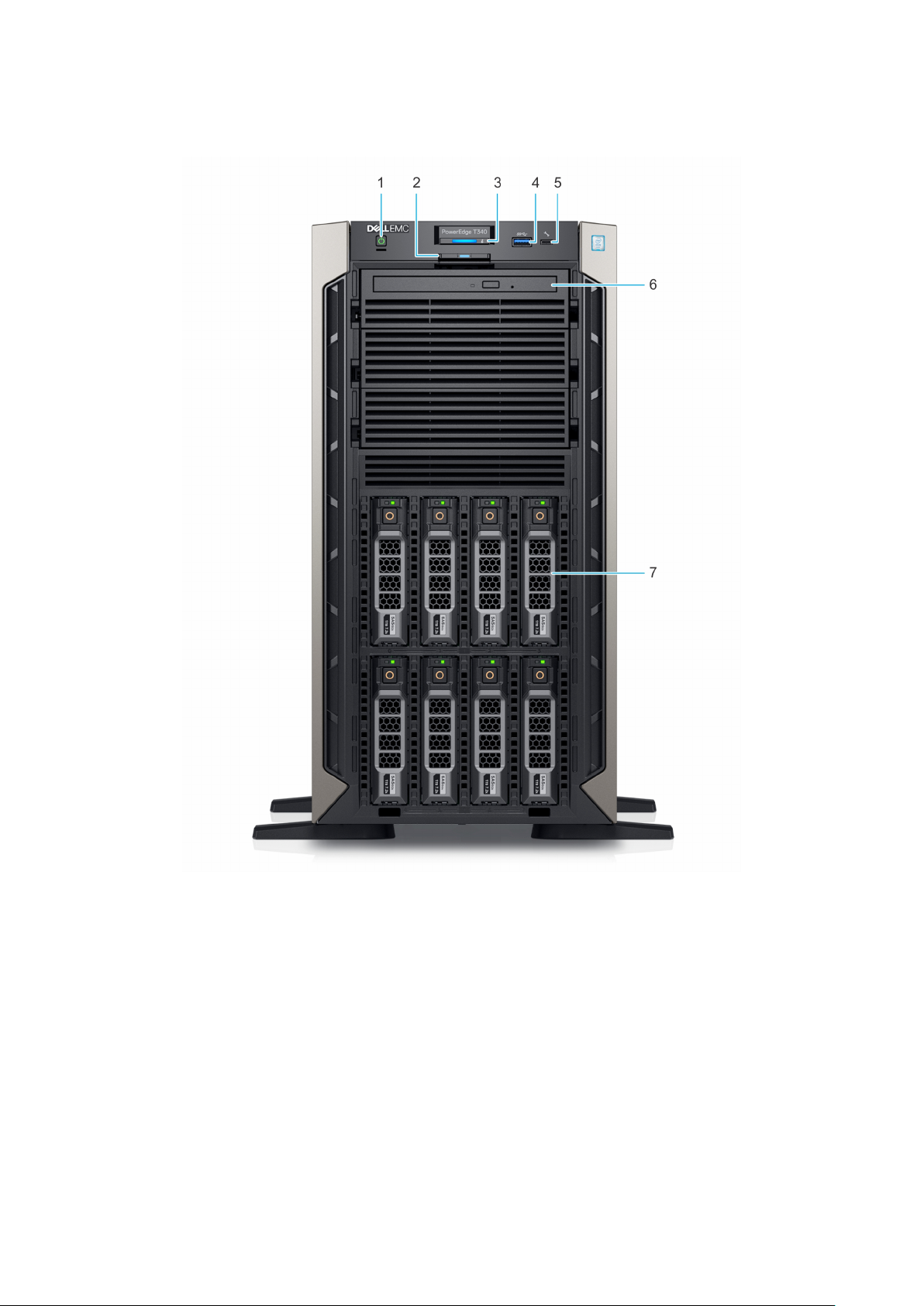
Front view of the system
Figure 1. Front view of 8 x 3.5-inch drive system
Power button 2. Information tag
1.
3. System health and system ID indicator 4. USB 3.0 port
5. iDRAC direct micro USB port 6. Optical drive (optional)
7. Drive (8)
For more information about the ports, see the Technical Specifications section.
Chassis views and features
9
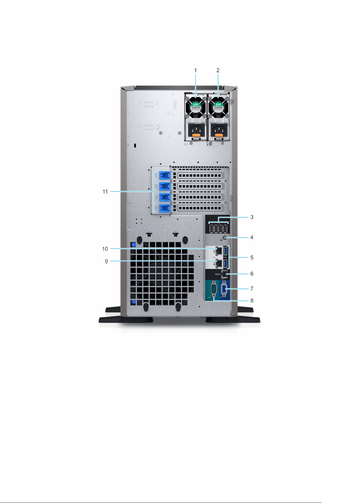
Rear view of the system
Figure 2. Rear view of 8 x 3.5-inch drive system
Power supply unit (PSU 1) 2. Power supply unit (PSU 2)
1.
3. USB 2.0 port (4) 4. System Identification button
5. USB 3.0 port (2) 6. iDRAC dedicated NIC port
7. VGA port 8. Serial port
9. NIC port (Gb1) 10. NIC port (Gb2)
11. PCIe expansion card slots (4)
10 Chassis views and features
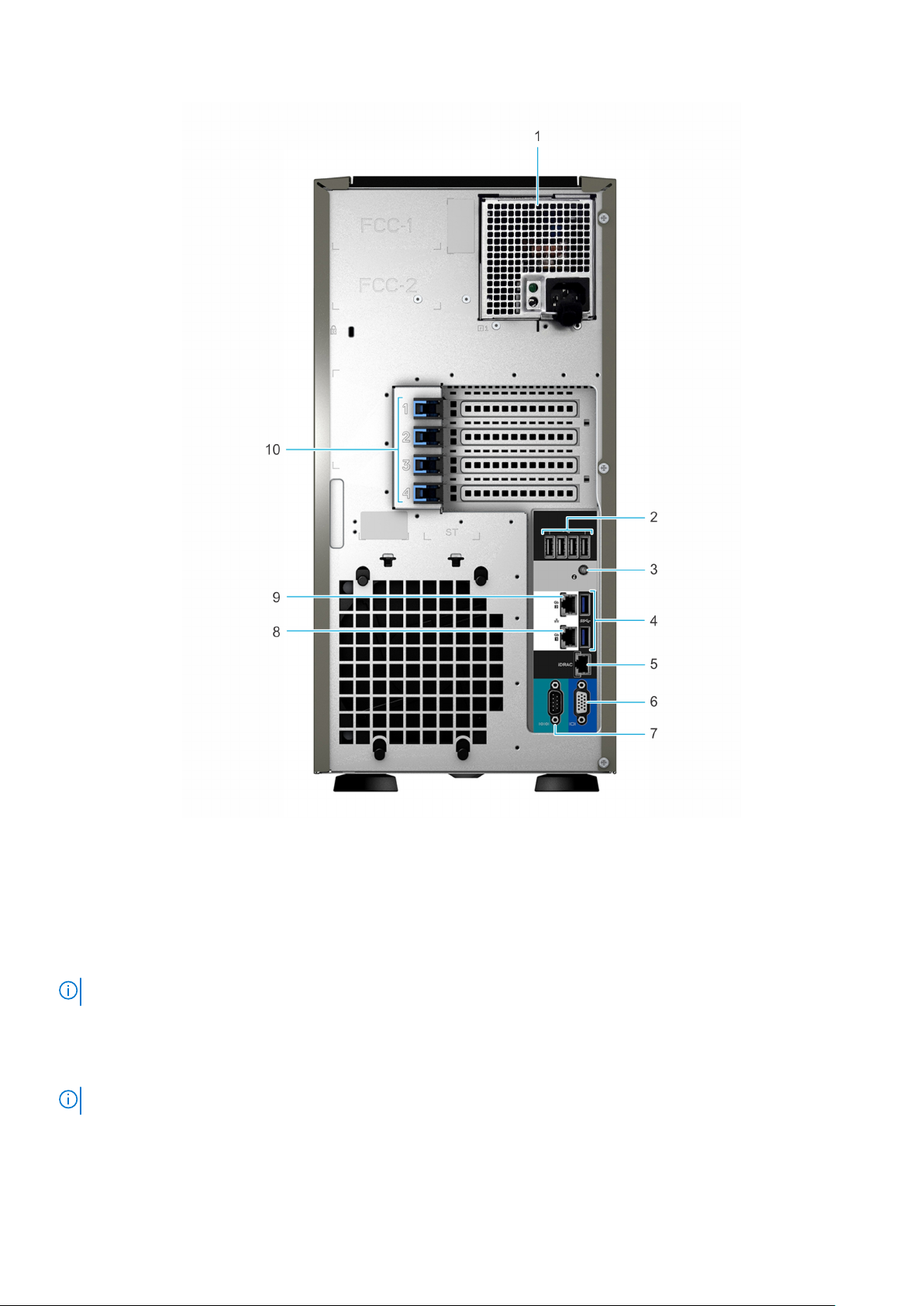
Figure 3. Rear view of 4 x 3.5-inch drive system
Cabled power supply unit (PSU) 2. USB 2.0 port (4)
1.
3. System identification button 4. USB 3.0 port (2)
5. iDRAC dedicated NIC port 6. VGA port
7. Serial port 8. NIC port (Gb1)
9. NIC port (Gb2) 10. PCIe expansion card slots (4)
NOTE: For more information about the ports and connectors, see the Technical Specifications section.
Inside the system
NOTE: Components that are hot swappable are marked orange and touch points on the components are marked blue.
Chassis views and features 11
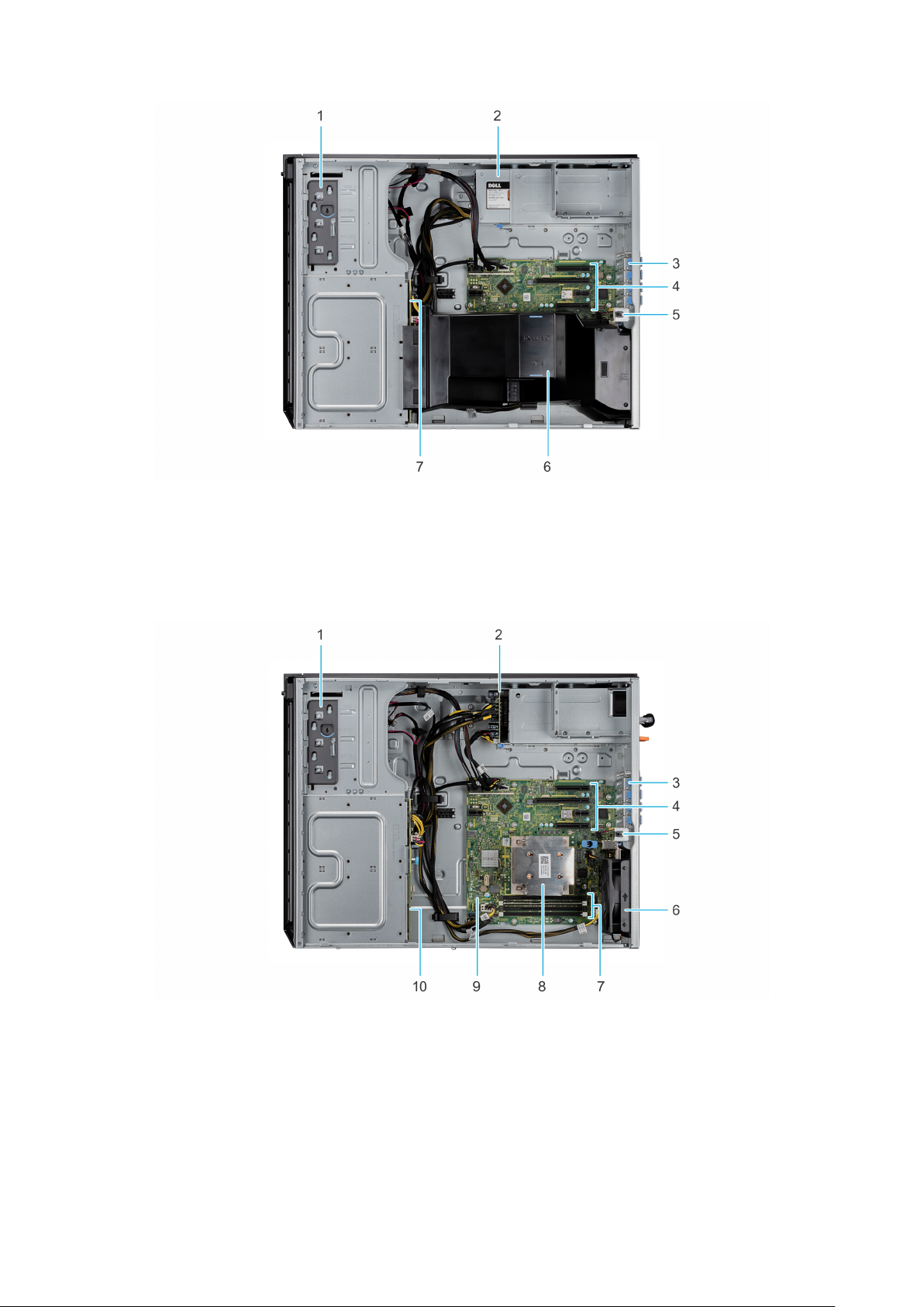
Figure 4. Inside the system with cabled power supply unit (PSU)
1. Optical drive or tape drive 2. Power supply unit (cabled)
3. PCIe Expansion card latch (4) 4. PCIe Expansion card slots (4)
5. Intrusion switch 6. Air shroud
7. Drive backplane
Figure 5. Inside the system with redundant power supply unit (PSU)
1.
Optical drive or tape drive 2. Power interposer board
3. PCIe Expansion card latch (4) 4. PCIe Expansion card slots (4)
5. Intrusion switch 6. Fan
7. Memory module socket (4) 8. Processor and heat sink
9. System board 10. Drive backplane
12 Chassis views and features

Locating the Service Tag of your system
You can identify your system using the unique Express Service Code and Service Tag. Pull out the information tag in front of the
system to view the Express Service Code and Service Tag. Alternatively, the information may be on a sticker on the chassis of
the system. The mini Enterprise Service Tag (EST) is found on the back of the system. This information is used by Dell to route
support calls to the appropriate personnel.
Figure 6. Locating Service Tag of your system
1. Information tag (top view) 2. Information tag (back view)
3. OpenManage Mobile (OMM) label 4. iDRAC MAC address and iDRAC secure password label
5. Service Tag
Chassis views and features 13

Processor
The PowerEdge T340 is a single-socket entry-level tower server with high availability features based on the Intel® Xeon®
E-2100 and E-2200 processor family.
Topics:
• Processor features
• Supported processors
• Chipset
Processor features
The following list highlights the features of the Intel® Xeon E-2100 and E-2200 processor family:
● Up to eight execution cores per processor
● Four DMI3 lanes
● 16 PCIe Gen 3 links capable of 8.0 GT/s
● Socket H4, LGA package (LGA1151)
● Integrated 2 channel DDR4 memory controller
● Execute Disable Bit
● Support Turbo Boost Technology 2.0
● Increases CPU frequency if operating below thermal, power, and current limits
● Intel® Virtualization Technology (Intel® VT)
4
NOTE:
We do not support graphics with E-2100 and E-2200 processors, Graphics cannot be enabled on Dell servers using
this processor due to technical restrictions.
Supported processors
The following table lists the supported processors for the PowerEdge T340:
Model
E-2288G 3.7 95 8 16 16 Yes 2666 Yes Yes
E-2286G 4 95 6 12 12 Yes 2666 Yes Yes
E-2278G 3.4 80 8 16 16 Yes 2666 Yes No
E-2276G 3.8 80 6 12 12 Yes 2666 Yes Yes
E-2274G 4 83 4 8 8 Yes 2666 Yes Yes
E-2246G 3.6 80 6 12 12 Yes 2666 Yes No
E-2244G 3.8 71 4 8 8 Yes 2666 Yes No
E-2236 3.4 80 6 12 12 Yes 2666 Yes No
Speed
(GHz)
Power
(Watts)
Cores L3 Cache
(MB)
Threads Turbo Max
Memory
Speed
(MT/s)
Hyperthreading
Intel
Software
Guard
Extensions
support
E-2234 3.6 71 4 8 8 Yes 2666 Yes No
E-2226G 3.4 80 6 12 6 Yes 2666 Yes No
E-2224 3.4 71 4 8 4 Yes 2666 Yes No
14 Processor

Model Speed
(GHz)
Power
(Watts)
Cores L3 Cache
(MB)
Threads Turbo Max
Memory
Speed
(MT/s)
Hyperthreading
Intel
Software
Guard
Extensions
support
Core i3
9100
Pentium
G5420
Celeron
G4930
E-2186G 3.8 95 6 12 12 Yes 2666 Yes Yes
E-2176G 3.7 80 6 12 12 Yes 2666 Yes Yes
E-2174G 3.8 71 4 8 8 Yes 2666 Yes Yes
E-2146G 3.5 80 6 12 12 Yes 2666 Yes No
E-2144G 3.6 71 4 8 8 Yes 2666 Yes No
E-2136 3.3 80 6 12 12 Yes 2666 Yes No
E-2134 3.5 71 4 8 8 Yes 2666 Yes No
E-2126G 3.3 80 6 12 6 Yes 2666 No No
E-2124 3.3 71 4 8 4 Yes 2666 No No
Core i3
8100
Pentium
G5500
3.6 65 4 6 4 Yes 2666 No No
3.8 58 2 4 4 Yes 2666 No No
3.2 54 2 2 4 Yes 2666 No No
3.6 65 4 6 4 No 2666 No No
3.8 54 2 4 2 No 2666 No No
Celeron
G4900
3.1 54 2 2 2 No 2666 No No
Chipset
The following table shows the high level features supported by the C246 chipset implemented on the PowerEdge T340:
PCH feature
TXT Y Y
Node Manager Y N
ECC Y Y
FlexIO - USB3.0 - 10 (means 6 is
enough)
USB 2.0 4 4
FlexIO - 8 SATA ports 8 5
FlexIO - SATA Express 3 0
FlexIO - PCIE 3.0 ports - additional
required
SPI (MB) FW image 7 UI
C246 T340
10 3
20 8
Intel vPRO/AMT11 Y N
Rapid Strorage technology Y N
Processor 15

PCH feature C246 T340
Rapid Strorage technology enterprise Y N
Data Center Graphics N N
supported displays 3 N
Int. Gbe MAC Y N
eSPI Y N
IO Flex - ability to change SATA/
PCIE/USB
Software Guard Extensions (SGX) N Y
The following table shows the features supported by the T340 chipset:
Y N
Table 3. Chipset features
Features Description
DMI interface Direct Media Interface 3 (DMI3) connects the CPU1 to the
chipset. DMI3 is similar to a four lane PCI Express supporting
a speed of 8 GT/s per lane.
PCI Express interface PCI Express Generation 3 (PCIe Gen3) is capable of 8 GT/s
bit rate (compared to PCIe Gen 2’s 5 GT/s) per lane. Because
PCIe Gen3 uses a “scrambling” encoding instead of PCIe
Gen2’s 8b/10b encoding, it is able to have double the
bandwidth of PCIe Gen2.
The PCIe Gen 3 will be fully compatible with prior generations
of this technology, from software to clocking architecture to
mechanical interfaces.
AHCI The chipset SATA controller provides hardware support for
Advanced Host Controller Interface (AHCI), a standardized
programming interface for SATA host controllers developed
through a joint industry effort. Platforms supporting AHCI may
take advantage of performance features such as port
independent DMA Engines—each device is treated as a
master—and hardware-assisted native command queuing.
Low Pin Count Interface (LPC) The chipset implements an LPC interface.
Serial Peripheral Interface (SPI) The chipset provides one Serial Peripheral Interface (SPI). The
interface implements 3 Chip Select signals (CS#), allowing up
to two flash devices and one TPM device to be connected to
the PCH. The CS0# and CS1# are used for flash devices and
CS2# is dedicated to TPM.
Advanced Programmable Interrupt Controller (APIC) The I/O APIC within the chipset supports 40 APIC interrupts.
Each interrupt has its own unique vector assigned by
software.
Real Time Clock (RTC) The Real-Time Clock (RTC) performs two key functions—
keeping track of the time of day and storing system data,
even when the system is powered down. The RTC operates
on a 32.768-KHz crystal and a 3V battery.
General-Purpose Input/Output (GPIO) GPIO Serial Expander (GSX) is the capability provided by the
PCH to expand the GPIOs on a platform that needs more
GPIOs than the ones provided by the PCH. The solution
requires external shift register discrete components.
System Management Bus (SMBus 2.0) The chipset provides a System Management Bus (SMBus) 2.0
host controller as well as an SMBus Slave Interface. The
chipset is also capable of operating in a mode in which it can
16 Processor

Table 3. Chipset features (continued)
Features Description
communicate with I2C compatible devices. The host SMBus
controller supports up to 100- KHz clock speed.
JTAG Boundary-Scan This section contains information regarding the chipset
testability signals that provides access to JTAG, run control,
system control, and observation resources. PCH JTAG (TAP)
ports are compatible with the IEEE Standard Test Access Port
and Boundary Scan Architecture 1149.1 and 1149.6
Specification, as detailed per device in each BSDL file. JTAG
Pin definitions are from IEEE Standard Test Access Port and
Boundary-Scan.
Processor 17

5
Memory
The PowerEdge T340 supports up to 4 DDR4 DIMMs. The T340 is designed to support the socket H4, Intel® Xeon® processor
E-2100 and E-2200 product family CPU, which has 2 memory channels per CPU, with each channel supporting up to 2 DIMMs.
The maximum system population at launch will be 64GB. The minimum system population is one 8GB DIMM.
Supported memory
The PowerEdge T340 supports memory with the following features:
● Unbuffer (UDIMM) ECC DDR4 technology
● Each channel carries 64 data and 8 ECC bits
● Up to 64 GB of UDIMM memory (4 x 16GB UDIMM)
● Up to 2666 MT/s DIMMs
● Flexible Memory Configuration
● ODT (On Die Termination)
● Clock gating (CKE) to conserve power when DIMMs are not accessed - DIMMs enter a low power self-refresh mode
● I²C access to SPD EEPROM for access to thermal sensors
● Memory Optimized (Independent Channel) Mode
● 100% Single Bit Error Correction
● Memory Off-lining is NOT supported
Memory speed
The system will run all memory on all CPUs and channels at the same speed and voltage. By default the system will run at the
highest speed for the lowest voltage of the worst case channel DIMM configuration.
Operating speed of the memory is determined by:
● Supported speed of the DIMMs
● DIMM configuration on any channel
● Max speed supported by the CPU
● Speed requested by user in BIOS setup screen
Operating voltage of the system is determined by:
● Voltages supported by the DIMMs which is 1.2V
●
Voltage supported by the platform
Memory population and configuration
The following table shows the supported memory configurations for the PowerEdge T340
DIMM Speed
2666 UDIMM 8 1 x8 Advanced ECC 1.2
2666 UDIMM 8 1 x8 Advanced ECC 1.2
DIMM Type DIMM
Capacity (GB)
Ranks per
DIMM
Data Width SDDC Support DIMM Volts
2666 UDIMM 16 1 x8 Advanced ECC 1.2
2666 UDIMM 16 1 x8 Advanced ECC 1.2
18 Memory

DIMM Speed DIMM Type DIMM
Capacity (GB)
2400 UDIMM 4 1 x8 Advanced ECC 1.2
2400 UDIMM 8 1 x8 Advanced ECC 1.2
2400 UDIMM 8 1 x8 Advanced ECC 1.2
2400 UDIMM 16 2 x8 Advanced ECC 1.2
2400 UDIMM 16 2 x8 Advanced ECC 1.2
2133 UDIMM 4 1 x8 Advanced ECC 1.2
2133 UDIMM 4 1 x8 Advanced ECC 1.2
2133 UDIMM 8 2 x8 Advanced ECC 1.2
2133 UDIMM 8 1 x8 Advanced ECC 1.2
2133 UDIMM 16 2 x8 Advanced ECC 1.2
2133 UDIMM 16 2 x8 Advanced ECC 1.2
The following table shows the memory populations and the system speed:
Ranks per
DIMM
Data Width SDDC Support DIMM Volts
Table 4. Memory populations and system speed
DIMM
Type
UDIMM 1R/2R 8GB, and 16GB DDR4 (1.2V) 2666 2666
DIMM Ranking Capacity DIMM Rated
voltage
1 DIMM per channel 2 DIMMs per
channel
Memory 19

6
Storage
The PowerEdge T340 supports up to 8 x 3.5-inch or 2.5-inch hot plug hard drives.
NOTE: Systems with x8 hard drive backplanes configured for software RAID supports only 4 hard drives. The remaining
hard drive slots are pre-installed with the four-slot hard drive blank, and cannot be upgraded for additional storage
Both 6Gbps and 12Gbps hard drives are supported. The following table shows the form factor and hard drive type supported by
the T340:
x8 hot plug hard drive with Redundant
PSU
Hard drive form factor 3.5-inch or 2.5-inch 3.5-inch or 2.5-inch
Hard drive type SATA, Nearline SAS, SAS, SSD SATA, Nearline SAS, SAS, SSD
Topics:
• Storage controller specifications
• Optical Drives
• Tape Drives
• Internal Dual SD Module
x4 hot plug hard drive (system ordered
with Software RAID)
Storage controller specifications
The Dell EMC PowerEdge T340 system supports S140 Software RAID, and H330, H730P RAID controllers. The PowerEdgeT340
systems supports HBA330 for Non-RAID (passthrough) configuration.
NOTE:
Dell RAID controller cards purchased after point-of-sell (APOS CUST Kits) are meant to replace or upgrade an
existing RAID controller card which would have been factory installed at the time the system was purchased. They are not
intended to be purchased for any system that was set up at the factory in a Software RAID configuration over to Hardware
RAID.
Optical Drives
One ultra-slim type, 9.5mm, ODD is supported on the PowerEdge T340 via the motherboard embedded SATA. The PowerEdge
T340 supports both the ultra-slim SATA DVD-ROM and DVD+/-RW.
If the drive is not ordered with the system, a blank should be installed in its place. ODD cable is 100% included in the chassis
even if no ODD is ordered. The PowerEdge T340 has 3 Half height 5.25” bays.
Tape Drives
The Dell EMC PowerEdge T340 supports internal and external tape drives.
The following table lists the supported tape drives for T340:
Internal tape drives
External tape backup unit
20 Storage
LTO-6, LTO-7, LTO-8 SAS
● RD1000 USB 3.0
● LTO-6, LTO-7, LTO-8 SAS

Internal Dual SD Module
The Internal Dual SD Module (IDSDM) is optional. The IDSDM contains two SD ports directly on the motherboard. The modules
are redundant. Supported iDSDM microSD cards capacity are 8/16/32/64GB
The IDSDM card provides the following functions:
● Dual SD interface is maintained in a mirrored configuration (primary and secondary SD)
● Provides full RAID1 functionality
● Dual SD cards are not required; the module can operate with only one card but will provide no redundancy
● Enables support for Secure Digital eXtended Capacity (SDXC) cards
● USB interface to host system
● I²C interface to host system and onboard EEPROM for out-of-band status reporting
● Onboard LEDs show status of each SD card
● A BIOS Setup Redundancy setting supports Mirror Mode or Disabled
Boot Optimized Storage Subsystem (BOSS)
BOSS is offered as a means of booting the PowerEdge T340 servers to a full OS when:
● A solution such as IDSDM may be desired, but the target OS for BOSS is a full OS (not just a hypervisor)
● The user needs to maximize their number of drive bays
BOSS cards take up a PCIe slot and are not hot-plug capable. 1x or 2x 240GB modules are available. Dual (2x) module configs
can be set up for either RAID 1 or No RAID. Single (1x) module configs can only be set up in a No RAID config.
Storage
21

Networking and PCIe
The following lists the supported add in communication cards:
● 10GbE Intel (Dual) Sageville Sage Pond Dual port 10Gb Base-T adapter – FH
● 10GbE Intel (Dual) Fortville Eagle Fountain Dual port 10Gb SFP+ adapter – FH
● 1GbE Intel (Dual) Powerville Troi-Stony Dual port 1Gb Base-T adapter – FH
● 1GbE Intel (Quad) Powerville Lore-Stony Quad port 1Gb Base-T adapter – FH
● 1GbE Broadcom (Dual) 5720 Bashir Dual port 1Gb Base-T adapter – FH
● 1GbE Broadcom (Quad) 5719 Cardassia Quad port 1Gb Base-T adapter – FH
● FC8 Emulex (Dual) Saturn Wildfire Dual port FC8 SFP+ adapter – FH
PCIe slots
The PowerEdge T340 provides four PCI Express expansion slots as follows:
● Slot 1 : x8 PCIe Gen3 for FH/HL from CPU (x8 lanes)
● Slot 2 : x16 PCIe Gen3 for FH/HL from CPU (x8 lanes)
● Slot 3 : x1 PCIe Gen3 for FH/HL from PCH (x1 lanes)
● Slot 4 : x8 PCIe Gen3 for FH/HL from PCH (x4 lanes)
The following table shows the PCIe slot location and specifications:
7
PCI Slot
1 PCIe x 8 PCIe x 8 Gen 3 Full Height Half Length
2 PCIe x16 PCIe x 8 Gen 3 Full Height Half Length
3 PCIe x 1 PCIe x 1 Gen 3 Full Height Half Length
4 PCIe x 8 PCIe x 4 Gen 3 Full Height Half Length
Mechanical Electrical Height Length
PCI card dimensions
The PCI card dimensions allowed in the PowerEdge T340 are as below:
Table 5. PCI card dimensions
Card type Height Length
Slot 1 (Full-Height, half
length card)
Slot 2 (Full-Height, half
length card)
Slot 3 (Full-Height, half
length card)
Slot 4 (Full-Height, half
length card)
69.37 mm (2.731 inches) max 167.65 mm (6.600 inches) max
69.37 mm (2.731 inches) max 167.65 mm (6.600 inches) max
69.37 mm (2.731 inches) max 167.65 mm (6.600 inches) max
69.37 mm (2.731 inches) max 167.65 mm (6.600 inches) max
22 Networking and PCIe

8
Power, thermal, and acoustics
Topics:
• Power supply units
Thermal
•
• Acoustics
Power supply units
The PowerEdge T340 power supply subsystem consists of one or two AC-DC power supplies (1+1 redundant configuration only
support on 86mm PSU). The power supply provides +12V and +12Vaux for non-redundant and redundant design. There are
several voltage regulators in the system to supply different voltage levels needed by different logic devices. The redundant
power supplies are managed through a PMBus interface.
There are two power supplies supported by the T340 :
Table 6. T340 Power supply units
T340 Cable PSU T340 Redundant PSU
350W AC 2U Cable Bronze v
495W AC 1U Redundant Platinum v
A redundant system consists of two power supplies in a 1+1 configuration. The power supplies connect directly to the system
board.
Thermal
Heat dissipation
NOTE: Heat dissipation is calculated using the power
supply wattage rating.
Voltage
NOTE: This system is also designed to be connected to IT
power systems with a phase-to-phase voltage not
exceeding 230 V.
1455 BTU/hr maximum (350 W PSU)
1908 BTU/hr maximum (495 W PSU)
100–240 V AC, autoranging, 50/60 Hz
Acoustics
PowerEdge T340 acoustics
Dell EMC PowerEdge T340 is a tower server appropriate for typical environment. However, lower acoustical output is attainable
with proper hardware or software configurations. For example, the minimum configuration of T340 is quiet enough for a quieter
office environment
Power, thermal, and acoustics 23

PowerEdge T340 acoustical dependencies
● Ambient Temperature. For a similar workload fan speeds (and thus, acoustical noise) may increase as ambient temperature
increases.
● High Wattage CPU. High-power (TDP) CPU parts may result in higher acoustical noise output.
● System Thermal Profile Selected in BIOS. The default setting is “Power Optimized (DAPC)”, which generally means
lower fan speed and acoustics. If “Performance Optimized” is selected, fan speed and acoustical noise may increase.
Methods to reduce acoustical output of the T340
● Although the T340 is designed for use in typical office environment, some users may prefer a quieter output. Dell EMC
suggests the following. It is important to note that in most cases, the baseline idle fan speed of the system cannot be
lowered without changing the configuration of the system, and in some cases, even a configuration change may not reduce
idle fan speeds.
● Reduce Ambient Temperature. Lowering the ambient temperature allows the system to cool components more efficiently
than at higher ambient temperatures.
● Optimize Third Party PCI Card Options.
● Replace Third Party PCI Cards with similar Dell Supported Temperature PCI Controlled Cards, if available. Dell EMC works
diligently with card vendors to validate and develop PCI cards to meet Dell EMC’s exacting standards for thermal
performance.
HDD Quantity. An incremental reduction in acoustical output may be gained by reducing the quantity of HDDs.
●
PowerEdge T340 Acoustical performance data
Acoustical performance for two configurations are provided: typical and feature rich. The following tables contains a summary of
the configuration and acoustical performance of the PE T340. Each configuration has been tested according to Dell EMC
acoustical standards for tower servers
Configuration
CPU Type Intel E2124 Intel E2124 Intel E2146G
CPU TDP 71 W 71 W 80 W
CPU Quantity 1 1 1
Memory Type 8GB, UDIMM 16GB, UDIMM 32GB, UDIMM
DIMM Quantity 1 2 4
Back Plane Type 4x 3.5" 8x 3.5" 8x 3.5"
HDD Type 7.2K RPM SATA 7.2K RPM SATA 10K RPM SAS
HDD Quantity 1 4 8
PSU Type 350W Cabled 495W Hot-Swap 495W Hot-Swap
PSU Quantity 1 2 2
Internal PERC None None PERC H330
Acoustical Performance: Idle/ Operating @ 25 °C Ambient
LwA-UL² (Bels) Idle¹ 3.8 3.9 4.3
Minimum Typical Feature Rich
Operating¹ 4.3 4.8 4.8
LpA³ (dBA) Idle¹ 23 26 27
Operating¹ 30 31 34
Acoustical Performance: Idle/ Operating @ 28 °C Ambient
LwA-UL² (Bels) 5.1 5.1 5.1
24 Power, thermal, and acoustics

Acoustical Performance: Idle/ Operating @ 28 °C Ambient
LpA³ (dBA) 35 35 35
Acoustical Performance: Max. Loading @ 35 °C Ambient
LwA-UL² (Bels) 6.8 6.8 6.8
LpA³ (dBA) 52 52 52
NOTE: 1. Idle means the state in which the product is doing nothing but running OS, and values for Operating are the
maximum of acoustical output for active HDDs or active processors.
NOTE: 2. LwA-UL is the upper limit sound power levels (LwA) calculated per section 4.4.1 of ISO 9296 (1988) with data
collected in accordance with ISO 7779 (2010) from a single sample with a total 0.3 bel production deviation applied.
NOTE: 3. LpA is the A-weighted sound pressure level at the bystander position per section 4.3 of ISO 9296 (1988) and
measured in accordance to ISO 7779 (2010).
Power, thermal, and acoustics 25

Supported operating systems
The following lists the supported operating systems for the PowerEdge T340:
● Windows 2019 with Hyper-V Standard
● Windows 2019 Essentials
● Windows 2016 with Hyper-V Standard
● Windows 2016 Essentials
● Windows 2012 R2 Essentials
● Windows 2012 R2 Standard
NOTE: Windows 2012 R2 is not supported with E-2200 processor configurations.
● RHEL 7.5
● SLES 15
● Ubuntu server 18.04.1
● Citrix XenServer 7.1
● VMWare ESXi 6.7
● VMWare ESXi 6.5
9
26 Supported operating systems

10
Dell EMC OpenManage systems management
Figure 7. Dell EMC OpenManage Portfolio
Dell EMC delivers management solutions that help IT Administrators effectively deploy, update, monitor, and manage IT assets.
OpenManage solutions and tools enable you to quickly respond to problems by helping them to manage Dell EMC servers
effectively and efficiently; in physical, virtual, local, and remote environments, operating in-band, and out-of-band (agent-free).
The OpenManage portfolio includes innovative embedded management tools such as the integrated Dell Remote Access
Controller (iDRAC), Chassis Management Controller and Consoles like OpenManage Enterprise, OpenManage Power Manager
plug in, and tools like Repository Manager.
Dell EMC has developed comprehensive systems management solutions based on open standards and has integrated with
management consoles that can perform advanced management of Dell hardware. Dell EMC has connected or integrated the
advanced management capabilities of Dell hardware into offerings from the industry's top systems management vendors and
frameworks such as Ansible, thus making Dell EMC platforms easy to deploy, update, monitor, and manage.
The key tools for managing Dell EMC PowerEdge servers are iDRAC and the one-to-many OpenManage Enterprise console.
OpenManage Enterprise helps the system administrators in complete lifecycle management of multiple generations of
PowerEdge servers. Other tools such as Repository Manager, which enables simple yet comprehensive change management.
OpenManage tools integrate with systems management framework from other vendors such as VMware, Microsoft, Ansible, and
ServiceNow. This enables you to use the skills of the IT staff to efficiently manage Dell EMC PowerEdge servers.
Topics:
• Server and Chassis Managers
• Dell EMC consoles
• Automation Enablers
• Integration with third-party consoles
• Connections for third-party consoles
• Dell EMC Update Utilities
• Dell resources
Dell EMC OpenManage systems management 27

Server and Chassis Managers
● Integrated Dell Remote Access Controller (iDRAC)
● iDRAC Service Module (iSM)
Dell EMC consoles
● Dell EMC OpenManage Enterprise
● Dell EMC Repository Manager (DRM)
● Dell EMC OpenManage Enterprise Power Manager plugin to OpenManage Enterprise
● Dell EMC OpenManage Mobile (OMM)
Automation Enablers
● OpenManage Ansible Modules
● iDRAC RESTful APIs (Redfish)
● Standards-based APIs (Python, PowerShell)
● RACADM Command Line Interface (CLI)
● GitHub Scripting Libraries
Integration with third-party consoles
● Dell EMC OpenManage Integrations with Microsoft System Center
● Dell EMC OpenManage Integration for VMware vCenter (OMIVV)
● Dell EMC OpenManage Ansible Modules
● Dell EMC OpenManage Integration with ServiceNow
Connections for third-party consoles
● Micro Focus and other HPE tools
● OpenManage Connection for IBM Tivoli
● OpenManage Plug-in for Nagios Core and XI
Dell EMC Update Utilities
● Dell System Update (DSU)
● Dell EMC Repository Manager (DRM)
● Dell EMC Update Packages (DUP)
● Dell EMC Server Update Utility (SUU)
● Dell EMC Platform Specific Bootable ISO (PSBI)
Dell resources
For additional information about white papers, videos, blogs, forums, technical material, tools, usage examples, and other
information, go to the OpenManage page at https://www.dell.com/openmanagemanuals or the following product pages:
28
Dell EMC OpenManage systems management

Table 7. Dell resources
Resource Location
Integrated Dell Remote Access Controller (iDRAC) https://www.dell.com/idracmanuals
iDRAC Service Module (iSM) https://www.dell.com/support/article/sln310557
OpenManage Ansible Modules https://www.dell.com/support/article/sln310720
OpenManage Essentials (OME) https://www.dell.com/support/article/sln310714
OpenManage Mobile (OMM) https://www.dell.com/support/article/sln310980
OpenManage Integration for VMware vCenter (OMIVV) https://www.dell.com/support/article/sln311238
OpenManage Integration for Microsoft System Center
(OMIMSSC)
Dell EMC Repository Manager (DRM) https://www.dell.com/support/article/sln312652
Dell EMC System Update (DSU) https://www.dell.com/support/article/sln310654
Dell EMC Platform Specific Bootable ISO (PSBI) Dell.com/support/article/sln296511
Dell EMC Chassis Management Controller (CMC) www.dell.com/support/article/sln311283
OpenManage Connections for Partner Consoles https://www.dell.com/support/article/sln312320
OpenManage Enterprise Power Manager https://www.dellemc.com/solutions/openmanage/power-
OpenManage Integration with ServiceNow (OMISNOW) Dell.com/support/article/sln317784
NOTE: Features may vary by server. Please refer to the product page on https://www.dell.com/manuals for details.
https://www.dell.com/support/article/sln312177
management.htm
Dell EMC OpenManage systems management 29

Appendix A. Additional specifications
The following sections contain information about additional system specifications.
Topics:
• Technical specifications
Technical specifications
The technical and environmental specifications of your system are outlined in this section.
Chassis dimensions
11
Figure 8. Chassis dimensions
Table 8. Dell EMC PowerEdge T340 chassis dimensions
Xa Xb Ya Yb Yc Za Zb Zc
218 mm (8.58
inches)
30 Appendix A. Additional specifications
307.9 mm
(12.12 inches)
430.3 mm
(16.94 inches)
443.3 mm
(17.45 inches)
471.3 mm
(18.56 inches)
With bezel:
14.1 mm (0.56
inches)
545.4 mm
(21.47 inches)
589.1 mm
(23.19 inches)

System weight
Table 9. Dell EMC PowerEdge T340 system chassis weight
System configuration Maximum weight (with all drives/SSDs)
8 x 3.5-inch drives 26 Kg (57.32 lb)
Video specifications
The Dell EMC PowerEdge T340 system supports integrated Matrox G200 graphics controller with 16 MB of video frame buffer.
Table 10. Supported video resolution options
Resolution Refresh rate (Hz) Color depth (bits)
640 x 480 60, 72 8, 16, 24
800 x 600 60, 75, 85 8, 16, 24
1024 x 768 60, 75, 85 8, 16, 24
1152 x 864 60, 75, 85 8, 16, 24
1280 x 1024 60, 75 8, 16, 24
USB ports specifications
Table 11. Dell EMC PowerEdge T340 system USB port specifications
Front panel Back panel Internal USB
● One USB 3.0-compliant port
● One iDRAC USB MGMT port (USB
2.0)
NOTE: The micro USB 2.0
compliant port can only be
used as an iDRAC Direct or a
management port.
● Two USB 3.0-compliant ports
● Four USB 2.0-compliant ports
● One internal USB 3.0-compliant port
NIC ports specifications
The Dell EMC PowerEdge T340 system supports up to two 10/100/1000 Mbps Network Interface Controller (NIC) ports that
are located on the back panel.
Environmental specifications
This section includes the environmental specifications for the PowerEdge T340
Feature
Temperature
Descriptions
● Maximum temperature gradient (Operating and storage)
○ 20 °C/h (36 °F/h)
● Storage temperature limits
○ –40 °C to 65 °C (–40 °F to 149 °F)
Relative humidity
● 5% to 95% RH with 33 °C (91 °F) maximum dew point.
Atmosphere must be noncondensing at all times.
Appendix A. Additional specifications 31

Feature Descriptions
Temperature (continuous operation)
Maximum vibration
Maximum shock
Maximum altitude
● Temperature ranges (for altitude less than 950 m or 3117
ft)
○ 10 °C to 35 °C (50 °F to 95 °F) with no direct
sunlight on the equipment.
● Humidity percentage range
○ 10% to 80% Relative Humidity with 29 °C(84.2 °F)
maximum dew point.
● Operating
○ 0.26 Grms at 5 Hz to 350 Hz (operationorientation).
● Storage
○ 1.88 Grms at 10 Hz to 500 Hz for 15 min (allsix sides
tested).
● Operating
○ Six consecutively executed shock pulses in the positive
and negative x, y, and z axes of 40 G for up to 2.3 ms.
● Storage
○ One pulse on each side of the system of 71 G up to 2
ms.
● Operating
○ 3,048 m (10,000 ft)
● Storage
○ 12,000 m (39,370 ft)
Operating Altitude De-rating, Up to 35 °C (95 °F)
Operating Altitude De-rating, 35 °C to 40 °C (95 °F to
104 °F)
Operating Altitude De-rating, 40 °C to 45 °C (104 °F to
113 °F)
● Maximum temperature is reduced by 1°C/300 m (1
°F/547 ft) above 950 m (3,117 ft).
● Maximum temperature is reduced by 1°C/175 m (1 °F/319
ft) above 950 (3,117 ft)
● Maximum temperature is reduced by 1°C/125 m (1 °F/228
ft) above 950 m (3,117 ft).
32 Appendix A. Additional specifications

Appendix B. Standards compliance
Table 12. Industry standard documents
Standard URL for information and specifications
12
ACPI Advance Configuration and Power Interface
Specification, v2.0c
Ethernet IEEE 802.3-2005 standards.ieee.org/getieee802/802.3.html
HDG Hardware Design Guide Version 3.0 for Microsoft
Windows Server
IPMI Intelligent Platform Management Interface, v2.0 intel.com/design/servers/ipmi
DDR4 Memory DDR4 SDRAM Specification jedec.org/standards-documents/docs/jesd79-4.pdf
PCI Express PCI Express Base Specification Rev. 2.0 and 3.0 pcisig.com/specifications/pciexpress
PMBus Power System Management Protocol Specification,
v1.2
SAS Serial Attached SCSI, v1.1 t10.org
SATA Serial ATA Rev. 2.6; SATA II, SATA 1.0a Extensions,
Rev. 1.2
SMBIOS System Management BIOS Reference Specification,
v2.7
TPM Trusted Platform Module Specification, v1.2 and v2.0 trustedcomputinggroup.org
UEFI Unified Extensible Firmware Interface Specification, v2.1 uefi.org/specifications
USB Universal Serial Bus Specification, Rev. 2.0 usb.org/developers/docs
acpi.info
microsoft.com/whdc/system/platform/pcdesign/desguide/
serverdg.mspx
pmbus.info/specs.html
sata-io.org
dmtf.org/standards/smbios
Appendix B. Standards compliance 33

Appendix C Additional resources
Table 13. Additional resources
Resource Description of contents Location
13
Installation and Service Manual
Getting Started Guide
Rack Installation Instructions This document ships with the rack kits, and provides
Information Update This document ships with the system, is also available in PDF
System Information Label The system information label documents the system board
This manual, available in PDF format, provides the following
information:
● Chassis features
● System Setup program
● System messages
● System codes and indicators
● System BIOS
● Remove and replace procedures
● Troubleshooting
● Diagnostics
● Jumpers and connectors
This guide ships with the system, and is also available in PDF
format. This guide provides the following information:
● Initial setup steps
● Key system features
● Technical specifications
instructions for installing a server in a rack.
format online, and provides information on system updates.
layout and system jumper settings. Text is minimized due to
space limitations and translation considerations. The label
size is standardized across platforms.
Dell.com/Support/Manuals
Dell.com/Support/Manuals
Dell.com/Support/Manuals
Dell.com/Support/Manuals
Inside the system chassis
cover
Quick Resource Locator (QRL) This code on the chassis can be scanned by a phone
application to access additional information and resources for
the server, including videos, reference materials, service tag
information, and Dell EMC contact information.
Energy Smart Solution Advisor
(ESSA)
34 Appendix C Additional resources
The Dell EMC online ESSA enables easier and more
meaningful estimates to help you determine the most
efficient configuration possible. Use ESSA to calculate the
power consumption of your hardware, power infrastructure,
and storage.
Inside the system chassis
cover
Dell.com/calc

Appendix D. Support and deployment
Topics:
• Dell EMC ProDeploy Enterprise Suite
• Deployment services
• Dell EMC Remote Consulting Services
• Dell EMC Data Migration Service
• ProSupport Enterprise Suite
• ProSupport Plus
• ProSupport
• ProSupport One for Data Center
• Support Technologies
• Additional professional services
• Dell Education Services
• Dell EMC Global Infrastructure Consulting Services
• Dell EMC Managed Services
14
services
Dell EMC ProDeploy Enterprise Suite
ProDeploy Enterprise Suite gets your server out of the box and into optimized production—fast. Our elite deployment engineers
with broad and deep experience utilizing best-in-class processes along with our established global scale can help you around the
clock and around the globe. From simple to the most complex server installations and software integration, we take the guess
work and risk out of deploying your new server technology.
Figure 9. ProDeploy Enterprise Suite capabilities
NOTE: Hardware installation not applicable on selected software products.
Dell EMC ProDeploy Plus
From beginning to end, ProDeploy Plus provides the skill and scale needed to successfully execute demanding deployments in
today's complex IT environments. Certified Dell EMC experts start with extensive environmental assessments and detailed
migration planning and recommendations. Software installation includes set up of most versions of Dell EMC SupportAssist and
Appendix D. Support and deployment services 35

OpenManage system management utilities. Post-deployment configuration assistance, testing, and product orientation services
are also available.
Dell EMC ProDeploy
ProDeploy provides full service installation and configuration of both server hardware and system software by certified
deployment engineers including set up of leading operating systems and hypervisors as well as most versions of Dell EMC
SupportAssist and OpenManage system management utilities. To prepare for the deployment, we conduct a site readiness
review and implementation planning exercise. System testing, validation, and full project documentation with knowledge transfer
complete the process.
Dell EMC Basic Deployment
Basic Deployment delivers worry-free professional installation by experienced technicians who know Dell EMC servers inside and
out.
Dell EMC Residency Services
Residency Services helps customers transition to new capabilities quickly with the assistance of on-site or remote Dell EMC
experts whose priorities and time you control. Residency experts can provide post implementation management and knowledge
transfer related to a new technology acquisition or day-to-day operational management of the IT infrastructure.
Deployment services
Deployment services details and exceptions can be found in service description documents at the Enterprise Configuration and
Deployment pageon Dell.com.
Dell EMC Remote Consulting Services
When you are in the final stages of your PowerEdge server implementation, you can rely on Dell EMC Remote Consulting
Services and our certified technical experts to help you optimize your configuration with best practices for your software,
virtualization, server, storage, networking, and systems management.
Dell EMC Data Migration Service
Protect your business and data with our single point of contact to manage your data migration project. Your project manager will
work with our experienced team of experts to create a plan using industry-leading tools and proven processes based on global
best practices to migrate your existing files and data so your business system get up and running quickly and smoothly.
ProSupport Enterprise Suite
With the ProSupport Enterprise Suite, we can help you keep your operation running smoothly, so you can focus on running your
business. We will help you maintain peak performance and availability of your most essential workloads. ProSupport Enterprise
Suite is a suite of support services that enable you to build the solution that is right for your organization. Choose support
models based on how you use technology and where you want to allocate resources. From the desktop to the data center,
address everyday IT challenges, such as unplanned downtime, mission-critical needs, data and asset protection, support
planning, resource allocation, software application management and more. Optimize your IT resources by choosing the right
support model.
36
Appendix D. Support and deployment services

Figure 10. ProSupport Enterprise Suite
ProSupport Plus
When you purchase PowerEdge servers, we recommend ProSupport Plus, our proactive and preventative support, for businesscritical systems. ProSupport Plus provides all the benefits of ProSupport, plus the following:
● An assigned Services Account Manager (SAM) who knows your business and your environment
● Access to senior ProSupport engineers for faster issue resolution
● Personalized, preventive recommendations based on analysis of support trends and best practices from across the Dell EMC
customer base to reduce support issues and improve performance
● Predictive analysis for issue prevention and optimization enabled by SupportAssist
● Proactive monitoring, issue detection, notification and automated case creation for accelerated issue resolution enabled by
SupportAssist
● On-demand reporting and analytics-based recommendations enabled by SupportAssist and TechDirect
ProSupport
Our ProSupport service offers highly trained experts around the clock and around the globe to address your IT needs. We will
help you minimize disruptions and maximize availability of your PowerEdge server workloads with:
● 24x7x365 access to certified hardware and software experts
● Collaborative 3rd party support
● Hypervisor and OS support
● Consistent level of support available for Dell EMC hardware, software and solutions
● Onsite parts and labor response options including next business day or four-hour mission critical
ProSupport One for Data Center
ProSupport One for Data Center offers flexible site-wide support for large and distributed data centers with more than 1,000
assets. This offering is built on standard ProSupport components that leverage our global scale but are tailored to your
Appendix D. Support and deployment services
37

company's needs. While not for everyone, it offers a truly unique solution for Dell EMC's largest customers with the most
complex environments.
● Team of assigned Services Account Managers (SAM) with remote, on-site options
● Assigned ProSupport One technical and field engineers who are trained on your environment and configurations
● On-demand reporting and analytics-based recommendations enabled by SupportAssist and TechDirect
● Flexible on-site support and parts options that fit your operational model
● A tailored support plan and training for your operations staff
Figure 11. ProSupport One for Data Center model
Support Technologies
Powering your support experience with predictive, data-driven technologies.
SupportAssist
The best time to solve a problem is before it happens. The automated proactive and predictive technology SupportAssist* helps
reduce steps and time to resolution, often detecting issues before they become a crisis. Benefits include:
● Value - SupportAssist is available to all customers at no additional charge.
● Improve productivity - replace manual, high-effort routines with automated support.
● Accelerate time to resolution - receive issue alerts, automatic case creation and proactive contact from Dell EMC experts.
● Gain insight and control - optimize enterprise devices with on-demand ProSupport Plus reporting in TechDirect and get
predictive issue detection before the problem starts.
SupportAssist is included with all support plans but features vary based on service level agreement.
Figure 12. SupportAssist model
Get started at Dell.com/SupportAssist
38
Appendix D. Support and deployment services

TechDirect
Boost your IT teams productivity when supporting Dell EMC systems. With over 1.4 million self-dispatches processed each year,
TechDirect has proven its effectiveness as a support tool. You can:
● Self-dispatch replacement parts
● Request technical support
● Integrate APIs into your help desk
Or, access all your Dell EMC certification and authorization needs. Train your staff on Dell EMC products as TechDirect allows
you to:
● Download study guides
● Schedule certification and authorization exams
● View transcripts of completed courses and exams
Register at techdirect.dell.com
Additional professional services
Dell Education Services
Dell Education Services offers the PowerEdge server training courses designed to help you achieve more with your hardware
investment. The curriculum is designed in conjunction with the server development team, as well as Dell EMC’s technical
support team, to ensure that the training delivers the information and practical, hands-on skills you and your team need to
confidently manage and maintain your Dell EMC server solution. To learn more or register for a class today, visit LearnDell.com/
Server.
Dell EMC Global Infrastructure Consulting Services
Dell EMC Global Infrastructure Consulting Services use skilled solution architects, innovative tools, automated analysis and Dell
EMC’s intellectual property to give rapid insight into the root causes of unnecessary complexity. We seek better answers than
traditional service models, and our strategy is to help quickly identify high-impact, short-duration projects that deliver return on
investment (ROI) and free up resources. The results are practical, action-oriented plans with specific, predictable, measurable
outcomes. From data center optimization to server virtualization to systems management, our consulting services can help build
a more efficient enterprise.
Dell EMC Managed Services
Dell EMC Managed Services are a modular set of lifecycle services designed to help you automate and centrally configure,
deploy, and manage your day-to-day data center operations. These services extend your existing on-premise IT infrastructure
with off-premise cloud services designed to better address challenges with mobility, highly distributed organizations, security,
compliance, business continuity, and disaster preparedness.
Appendix D. Support and deployment services
39
 Loading...