

Dell SC4020 Deployment Manual

Dell Storage Center
SC4020 Storage System
Deployment Guide

Notes, Cautions, and Warnings
NOTE: A NOTE indicates important information that helps you make better use of your computer.
CAUTION: A CAUTION indicates either potential damage to hardware or loss of data and tells you
how to avoid the problem.
WARNING: A WARNING indicates a potential for property damage, personal injury, or death.
© 2016 Dell Inc. All rights reserved. This product is protected by U.S. and international copyright and intellectual
property laws. Dell and the Dell logo are trademarks of Dell Inc. in the United States and/or other jurisdictions. All other
marks and names mentioned herein may be trademarks of their respective companies.
2016 - 08
Rev. G

Contents
About this Guide.......................................................................................................8
Revision History.....................................................................................................................................8
Audience................................................................................................................................................8
Contacting Dell..................................................................................................................................... 8
Related Publications..............................................................................................................................8
1 About the SC4020 Storage System................................................................. 10
Storage Center Hardware Components............................................................................................ 10
SC4020 Storage System................................................................................................................10
Switches.........................................................................................................................................10
Expansion Enclosures....................................................................................................................10
Storage Center Architecture Options................................................................................................. 11
Storage Center Communication.........................................................................................................12
Front-End Connectivity.................................................................................................................12
Back-End Connectivity..................................................................................................................15
System Administration...................................................................................................................16
SC4020 Storage System Hardware.................................................................................................... 16
SC4020 Storage System Front-Panel Features and Indicators................................................... 16
SC4020 Storage System Back-Panel Features and Indicators.................................................... 17
SC4020 Storage System Storage Controller Features and Indicators ....................................... 19
SC4020 Storage System Drives.................................................................................................... 24
SC4020 Storage System Drive Numbering..................................................................................24
SC200/SC220 Expansion Enclosure Overview..................................................................................25
SC200/SC220 Expansion Enclosure Front-Panel Features and Indicators................................ 25
SC200/SC220 Expansion Enclosure Back-Panel Features and Indicators.................................26
SC200/SC220 Expansion Enclosure EMM Features and Indicators............................................27
SC200/SC220 Expansion Enclosure Drives................................................................................. 28
SC200/SC220 Expansion Enclosure Drive Numbering...............................................................28
SC280 Expansion Enclosure Overview.............................................................................................. 29
SC280 Expansion Enclosure Front-Panel Features and Indicators.............................................29
SC280 Expansion Enclosure Back-Panel Features and Indicators..............................................31
SC280 Expansion Enclosure Drives..............................................................................................34
SC280 Expansion Enclosure Drive Numbering............................................................................35
2 Install the Storage Center Hardware.............................................................. 36
Unpack and Inventory the Storage Center Equipment..................................................................... 36
Prepare the Installation Environment.................................................................................................36
Gather Required Materials...................................................................................................................37
Safety Precautions...............................................................................................................................37
3

Installation Safety Precautions......................................................................................................37
Electrical Safety Precautions.........................................................................................................38
Electrostatic Discharge Precautions.............................................................................................38
General Safety Precautions...........................................................................................................38
Install the Storage System in a Rack...................................................................................................39
Installing Hard Drives in a Storage System.........................................................................................42
Installing Hard Drives in an SC200/SC220 Expansion Enclosure..................................................... 42
Installing the Hard Drives in an SC280 Expansion Enclosure........................................................... 44
3 Connect the Front-End Cabling...................................................................... 48
Front-End Connectivity Modes..........................................................................................................48
Virtual Port Mode.......................................................................................................................... 48
Legacy Mode................................................................................................................................. 50
Types of Redundancy for Front-End Connections........................................................................... 52
Failover Behavior........................................................................................................................... 53
Multipath I/O..................................................................................................................................53
Fibre Channel Zoning......................................................................................................................... 54
WWN Zoning Guidelines...............................................................................................................54
Cabling SAN-Attached Host Servers.................................................................................................. 55
Connecting to Fibre Channel Host Servers..................................................................................55
Connecting to iSCSI Host Servers................................................................................................ 66
Cabling Direct-Attached Host Servers............................................................................................... 75
Preparing Host Servers..................................................................................................................75
SAS Virtual Port Mode....................................................................................................................75
Four Servers Connected to Dual 12 Gb 4-Port SAS Storage Controllers................................... 76
Four Servers (Two HBAs Per Server) Connected to Dual 12 Gb 4-Port SAS Storage
Controllers..................................................................................................................................... 77
Two Servers Connected to Dual 12 Gb 4-Port SAS Storage Controllers....................................79
Labeling the Front-End Cables.....................................................................................................80
Cabling the Ethernet Management Port.............................................................................................81
Labeling the Ethernet Management Cables.................................................................................82
Cabling the Embedded Ports for iSCSI Replication...........................................................................83
Cabling the Replication Port for iSCSI Replication...................................................................... 83
Cabling the Management Port and Replication Port for iSCSI Replication................................84
Cabling the Embedded Ports for iSCSI Host Connectivity................................................................85
Two iSCSI Networks using the Embedded Ethernet Ports on a Storage System with Fibre
Channel Storage Controllers........................................................................................................ 85
Two iSCSI Networks Using the Embedded Ethernet Ports on a Storage System with iSCSI
Storage Controllers....................................................................................................................... 87
4 Connect the Back-End Cabling.......................................................................89
Expansion Enclosure Cabling Guidelines...........................................................................................89
4

Back-End SAS Redundancy.......................................................................................................... 89
Back-End SAS Port Types............................................................................................................. 89
Back-End Connections for an SC4020 Storage System Without Expansion Enclosures............... 90
Back-End Connections for an SC4020 Storage System With Expansion Enclosures..................... 90
SC4020 Storage System and One SC200/SC220 Expansion Enclosure.................................... 91
SC4020 Storage System and Two or More SC200/SC220 Expansion Enclosures....................92
Back-end Connections for an SC4020 with SC280 Expansion Enclosures.................................... 93
SC4020 and One SC280 Expansion Enclosure........................................................................... 93
SC4020 and Two SC280 Expansion Enclosures......................................................................... 94
Label the Back-End Cables.................................................................................................................95
5 Set up Storage Center Software.......................................................................97
Prerequisites........................................................................................................................................ 97
Hardware Configuration............................................................................................................... 97
Required Materials.........................................................................................................................97
Required Documents....................................................................................................................98
Required Software Versions..........................................................................................................98
Connect Power Cables and Turn On the Storage System................................................................98
Establish a Serial Connection to the Top Storage Controller.........................................................100
Configure the Top Storage Controller............................................................................................. 101
Establish a Serial Connection to the Bottom Storage Controller................................................... 103
Configure the Bottom Storage Controller.......................................................................................104
Start the Storage Center Startup Wizard..........................................................................................106
Completing the Storage Center Startup Wizard..............................................................................109
License Agreement Page............................................................................................................ 109
Load License Page...................................................................................................................... 109
Create Disk Folder Page.............................................................................................................. 110
Add Controller Page.................................................................................................................... 114
Time Settings Page...................................................................................................................... 118
System Setup Page...................................................................................................................... 119
Configure SMTP Page..................................................................................................................121
Update Setup Page......................................................................................................................122
User Setup Page.......................................................................................................................... 123
Configure IO Cards Page............................................................................................................ 124
Configure Ports Page.................................................................................................................. 125
Generate SSL Cert Page.............................................................................................................. 137
6 Perform Post-Setup Tasks..............................................................................140
Install Dell Storage Manager Client 2016.........................................................................................140
Send Diagnostic Data Using Dell SupportAssist.............................................................................. 140
Put the Storage Center Into Maintenance Mode.............................................................................140
Updating the Storage Center Software............................................................................................140
5

Verify Connectivity and Failover....................................................................................................... 141
Create Test Volumes................................................................................................................... 141
Test Basic Connectivity............................................................................................................... 141
Test Storage Controller Failover.................................................................................................142
Test MPIO.................................................................................................................................... 142
Clean Up Test Volumes...............................................................................................................143
Send Diagnostic Data Using Dell SupportAssist...............................................................................143
Label SC200/SC220 Expansion Enclosures.....................................................................................143
Next Steps..........................................................................................................................................144
A Adding or Removing an Expansion Enclosure............................................145
Adding Multiple Expansion Enclosures to a Storage System Deployed without Expansion
Enclosures......................................................................................................................................... 145
Cable the Expansion Enclosures Together................................................................................ 146
Check the Disk Count before Adding an Expansion Enclosure................................................146
Add the SC200/SC220 Expansion Enclosures to the A-Side of the Chain...............................146
Add the SC200/SC220 Expansion Enclosures to the B-Side of the Chain...............................147
Adding an SC200/SC220 Expansion Enclosure to an SC4020 Deployed with Expansion
Enclosures......................................................................................................................................... 149
Check the Disk Count before Adding an Expansion Enclosure................................................ 150
Add an SC200/SC220 Expansion Enclosure to the A-Side of the Chain..................................150
Add an SC200/SC220 Expansion Enclosure to the B-Side of the Chain.................................. 151
Adding an SC280 Expansion Enclosure to an SC4020 Deployed without Expansion
Enclosures......................................................................................................................................... 153
Check the Disk Count before Adding an Expansion Enclosure................................................ 153
Add the SC280 Expansion Enclosure to the A-Side of the Chain.............................................154
Add the SC280 Expansion Enclosure to the B-Side of the Chain.............................................154
Adding an SC280 Expansion Enclosure to an SC4020 Deployed with One SC280 Expansion
Enclosure...........................................................................................................................................156
Check the Disk Count before Adding an Expansion Enclosure................................................ 156
Add a Second SC280 Expansion Enclosure to the A-Side of the Chain................................... 157
Add a Second SC280 Expansion Enclosure to the B-Side of the Chain...................................158
Label the Back-End Cables...............................................................................................................160
Removing an Expansion Enclosure from a Chain Currently in Service...........................................161
Release the Disks in the Expansion Enclosure........................................................................... 162
Disconnect the SC200/SC220 Expansion Enclosure from the A-Side of the Chain............... 162
Disconnect the SC200/SC220 Expansion Enclosure from the B-Side of the Chain............... 164
Removing an SC280 Expansion Enclosure from a Chain Currently in Service.............................. 165
Release the Disks in the Expansion Enclosure...........................................................................166
Disconnect the SC280 Expansion Enclosure from the A-Side of the Chain............................166
Disconnect the SC280 Expansion Enclosure from the B-Side of the Chain............................168
B HBA Server Settings..........................................................................................171
Settings by HBA Manufacturer.......................................................................................................... 171
6

Dell 12Gb SAS Cards.................................................................................................................... 171
Cisco Fibre Channel Cards.......................................................................................................... 171
Emulex HBA Cards....................................................................................................................... 171
QLogic HBA Cards.......................................................................................................................172
Settings by Server Operating System................................................................................................173
Citrix XenServer................................................................................................................................. 173
Versions 5.x to 6.2........................................................................................................................173
Version 6.5................................................................................................................................... 173
HP-UX 11i...........................................................................................................................................174
V 2 and Earlier .............................................................................................................................174
V 3................................................................................................................................................ 174
IBM AIX ..............................................................................................................................................174
Microsoft Windows Server................................................................................................................ 174
Microsoft MPIO Settings..............................................................................................................175
Novell Netware .................................................................................................................................175
Oracle Solaris ....................................................................................................................................175
Red Hat Enterprise Linux...................................................................................................................175
Version 5.x....................................................................................................................................176
Version 6.x................................................................................................................................... 176
SuSE Linux .........................................................................................................................................177
Non-Boot from SAN.................................................................................................................... 177
Boot from SAN.............................................................................................................................177
C iSCSI Settings.................................................................................................... 179
Flow Control Settings........................................................................................................................179
Ethernet Flow Control.................................................................................................................179
Switch Ports and Flow Control................................................................................................... 179
Flow Control................................................................................................................................179
Jumbo Frames and Flow Control............................................................................................... 179
Other iSCSI Settings..........................................................................................................................180
D Troubleshooting Storage Center Deployment.......................................... 183
Troubleshooting the Serial Connection to a Storage Controller....................................................183
Troubleshooting Expansion Enclosures...........................................................................................183
Troubleshooting Storage Center Licenses...................................................................................... 184
Troubleshooting the Storage Center Startup Wizard......................................................................184
7

About this Guide
This guide describes how to install and configure an SC4020 storage system.
Revision History
Document Number: 690-052-001
Revision Date Description
A May 2014 Initial release
B June 2014 Updated the storage controller configuration instructions and
removed a reference to an internal document
C August 2014 Added information about iSCSI front-end connectivity
D October 2014 Added information about SFP+ transceiver modules and
contacting Dell technical support
E June 2015 Added information about new features for SC4020 storage
systems running Storage Center 6.6.4 or later
F December 2015 Added information about 16 Gb Fibre Channel front-end
connectivity
G August 2016 Added information about 12 Gb front-end SAS connectivity
Audience
The information provided in this Deployment Guide is intended for use by Dell installers and Dell business
partners.
Contacting Dell
Dell provides several online and telephone-based support and service options. Availability varies by
country and product, and some services might not be available in your area.
To contact Dell for sales, technical support, or customer service issues, go to www.dell.com/support.
• For customized support, type your system service tag on the support page and click Submit.
• For general support, browse the product list on the support page and select your product.
Related Publications
The following documentation is available for the SC4020 storage system.
• Dell Storage Center SC4020 Storage System Getting Started Guide
Provides information about an SC4020 storage system, such as installation instructions and technical
specifications.
• Dell Storage Center SC4020 Storage System Owner’s Manual
8

Provides information about an SC4020 storage system, such as hardware features, replacing
customer replaceable components, and technical specifications.
• Dell Storage Center SC4020 Storage System Service Manual
Provides information about an SC4020 storage system, such as hardware features, replacing field
replaceable components, and technical specifications.
• Dell Storage Center SC4000 Series Virtual Media Update Instructions
Describes how to update Storage Center software on an SC4000 series storage system using virtual
media. Updating Storage Center software using the Storage Center Virtual Media option is intended
for use only by sites that cannot update Storage Center using standard methods.
• Dell Storage Center Release Notes
Contains information about new features and known and resolved issues for the Storage Center
software.
• Dell Storage Center System Manager Administrator’s Guide
Describes the Storage Center System Manager software that manages an individual Storage Center.
• Dell Storage Center Software Update Guide
Describes how to update Storage Center software from an earlier version to the current version.
• Dell Storage Center Command Utility Reference Guide
Provides instructions for using the Storage Center Command Utility. The Command Utility provides a
command-line interface (CLI) to enable management of Storage Center functionality on Windows,
Linux, Solaris, and AIX platforms.
• Dell Storage Center Command Set for Windows PowerShell
Provides instructions for getting started with Windows PowerShell cmdlets and scripting objects that
interact with the Storage Center using the PowerShell interactive shell, scripts, and PowerShell hosting
applications. Help for individual cmdlets is available online.
• Dell TechCenter
Provides technical white papers, best practice guides, and frequently asked questions about Dell
Storage products. Go to http://en.community.dell.com/techcenter/storage/.
9

1
About the SC4020 Storage System
The SC4020 storage system provides the central processing capabilities for the Storage Center Operating
System and management of RAID storage.
Storage Center Hardware Components
The Storage Center described in this document consists of an SC4020 storage system, enterprise-class
switches, and expansion enclosures.
To allow for storage expansion, the SC4020 storage system supports multiple SC200/SC220 expansion
enclosures and SC280 expansion enclosures.
NOTE: The cabling between the storage system, switches, and host servers is referred to as front‐
end connectivity. The cabling between the storage system and expansion enclosures is referred to
as back-end connectivity.
SC4020 Storage System
The SC4020 is a 2U storage system that supports a minimum of 7 and a maximum of 24 internal 2.5-inch
hot-swappable SAS hard drives installed horizontally side-by-side.
The SC4020 storage system contains two redundant power supply/cooling fan modules and two storage
controllers with multiple I/O ports that provide communication with servers and expansion enclosures.
Switches
Dell offers enterprise-class switches as part of the total Storage Center solution.
The SC4020 storage system supports Fibre Channel (FC) and Ethernet switches, which provide robust
connectivity to servers and allow for the use of redundant transport paths. Fibre Channel (FC) or Ethernet
switches can provide connectivity to a remote Storage Center to allow for replication of data. In addition,
Ethernet switches provide connectivity to a management network to allow configuration, administration,
and management of the Storage Center.
Expansion Enclosures
Expansion enclosures allow the data storage capabilities of the SC4020 storage system to be expanded
beyond the 24 internal disks in the storage system chassis.
An SC4020 a total of 192 disks per Storage Center system. This total includes the disks in the storage
system chassis and the disks in the SC200/SC220 expansion enclosures or SC280 expansion enclosures.
An SC4020 can support:
• Up fourteen SC200 expansion enclosures
• Up to seven SC220 expansion enclosures
• Any combination of SC200/SC220 expansion enclosures, as long as the total disk count of the system
does not exceed 192
10
About the SC4020 Storage System
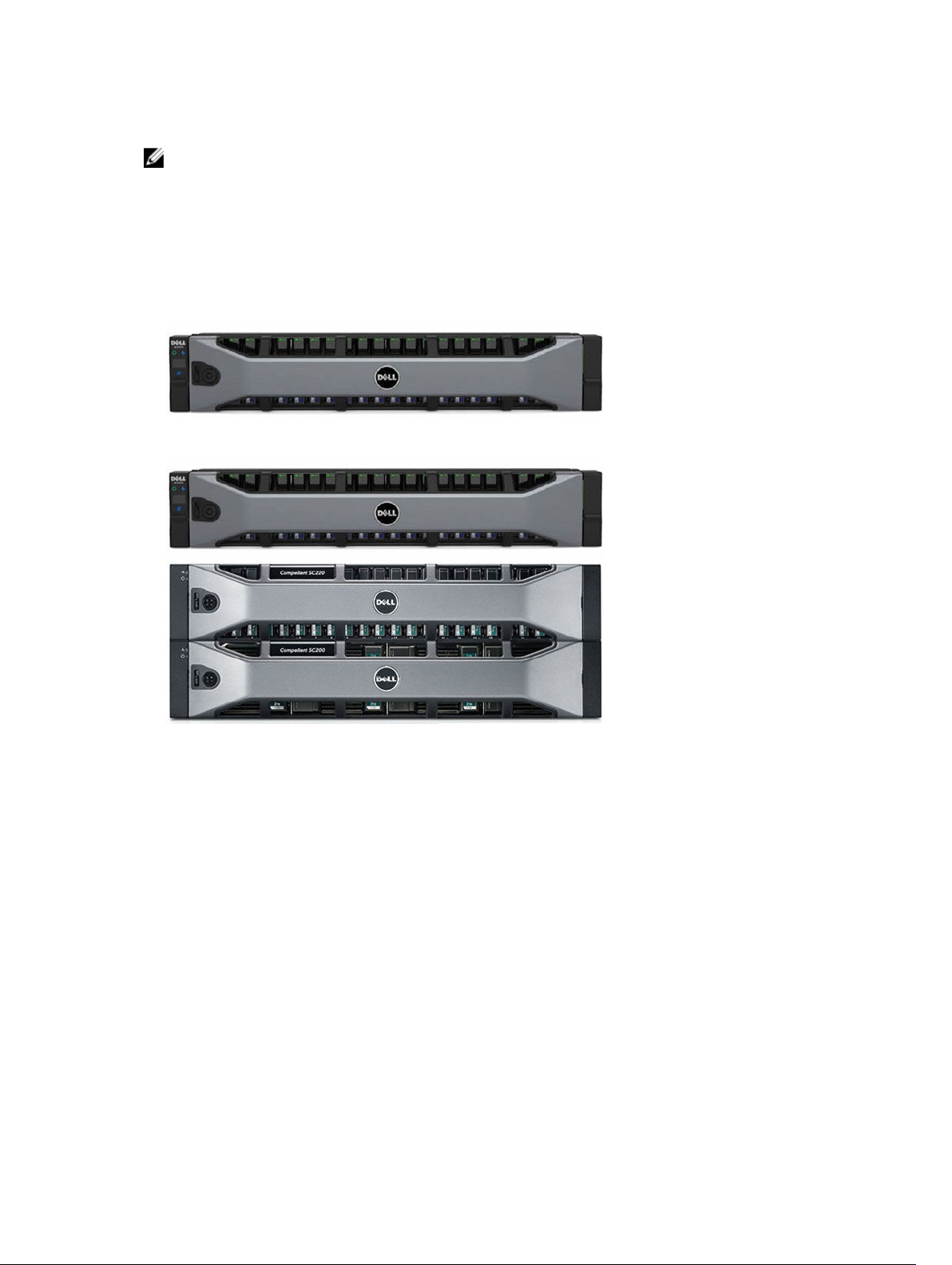
• Up to two SC280 expansion enclosures
NOTE: An SC4020 storage system cannot be connected to both SC200/SC220 expansion
enclosures and SC280 expansion enclosures at the same time. The SC4020 supports only a single
chain of SC200/SC220 expansion enclosures or a single chain of SC280 expansion enclosures.
Storage Center Architecture Options
A Storage Center with an SC4020 storage system can be deployed in the following configurations:
• An SC4020 storage system deployed without SC200/SC220 expansion enclosures.
Figure 1. SC4020 Storage System without Expansion Enclosures
• An SC4020 storage system deployed with one or more SC200/SC220 expansion enclosures.
Figure 2. SC4020 Storage System with Two SC200/SC220 Expansion Enclosures
• An SC4020 storage system deployed with up to two SC280 expansion enclosures.
About the SC4020 Storage System
11
Figure 3. SC4020 Storage System with Two SC280 Expansion Enclosures
Storage Center Communication
A Storage Center uses multiple types of communication for both data transfer and administrative
functions.
Storage Center communication is classified into three types: front end, back end, and system
administration.
Front-End Connectivity
Front-end connectivity provides I/O paths from servers to a storage system and replication paths from
one Storage Center to another Storage Center. The SC4020 storage system provides the following types
of front-end connectivity:
• Fibre Channel: Hosts, servers, or Network Attached Storage (NAS) appliances access storage by
connecting to the storage system Fibre Channel ports through one or more Fibre Channel switches.
Connecting host servers directly to the storage system, without using Fibre Channel switches, is not
supported.
When replication is licensed, the SC4020 can use the front-end Fibre Channel ports to replicate data
to another Storage Center.
• iSCSI: Hosts, servers, or Network Attached Storage (NAS) appliances access storage by connecting to
the storage system iSCSI ports through one or more Ethernet switches. Connecting host servers
directly to the storage system, without using Ethernet switches, is not supported.
12
About the SC4020 Storage System
When replication is licensed, the SC4020 can use the front-end iSCSI ports to replicate data to
another Storage Center.
• SAS: Hosts or servers access storage by connecting directly to the storage system SAS ports.
NOTE: When replication is licensed on an SC4020 the SC4020 can use the embedded MGMT and
REPL ports to perform iSCSI replication to another Storage Center. In addition, the SC4020 can use
the embedded MGMT and REPL ports as front-end iSCSI ports for connectivity to host servers.
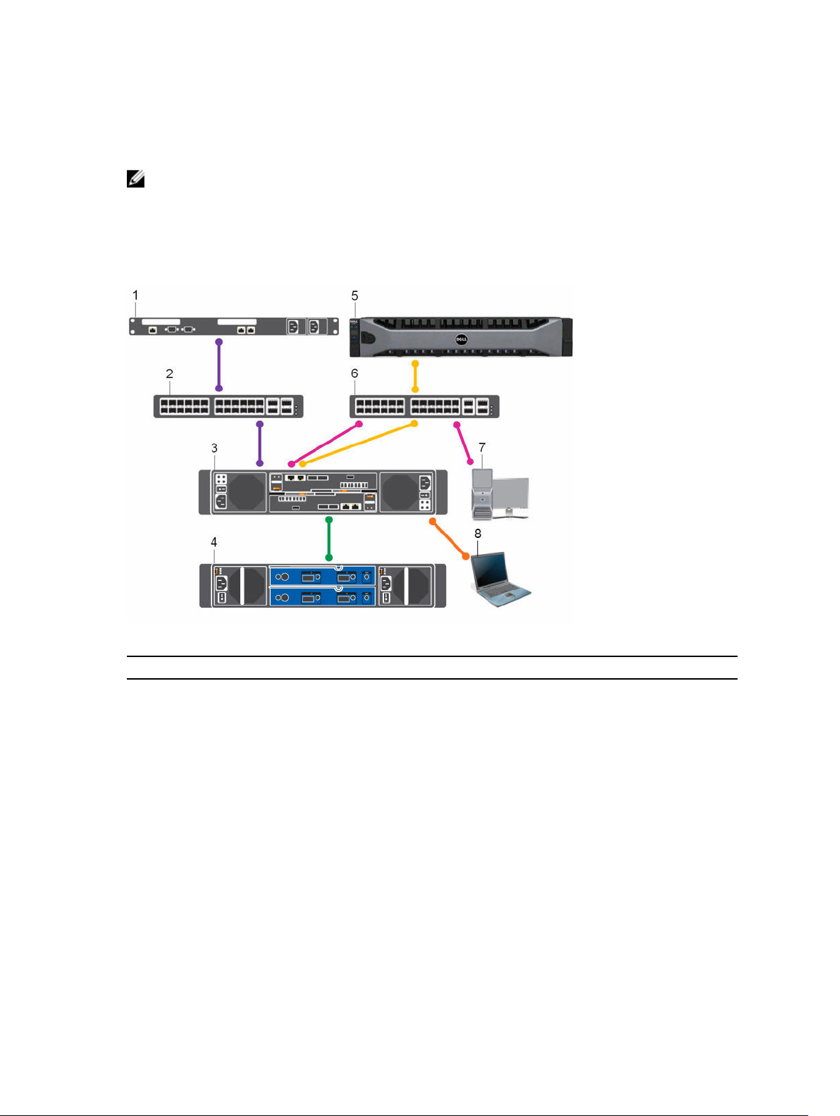
SC4020 Storage System with Fibre Channel Front-End Connectivity
An SC4020 storage system with Fibre Channel front-end connectivity may communicate with the
following components of a Storage Center system.
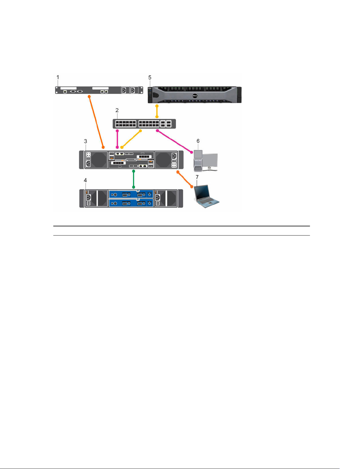
Figure 4. Storage System with Fibre Channel Front-End Connectivity
Item Description Speed Communication Type
1 Server with Fibre Channel host bus adapters
8 Gbps or 16 Gbps Front End
(HBAs)
2 Fibre Channel switch 8 Gbps or 16 Gbps Front End
3 SC4020 Storage System with FC front-end
8 Gbps or 16 Gbps Front End
connectivity
4 SC200/SC220 Expansion Enclosures 6 Gbps per channel Back End
5 Remote Storage Center connected via iSCSI
1 Gbps or 10 Gbps Front End
for replication
6 Ethernet switch 1 Gbps or 10 Gbps
Front End
(Management/
Replication)
7 Management network (computer connected
Up to 1 Gbps System Administration
to the storage system through the Ethernet
switch)
About the SC4020 Storage System
13
Item Description Speed Communication Type
8 Computer connected to the SC4020
through a serial connection
115,200 Kbps System Administration
(Service and installation
only)
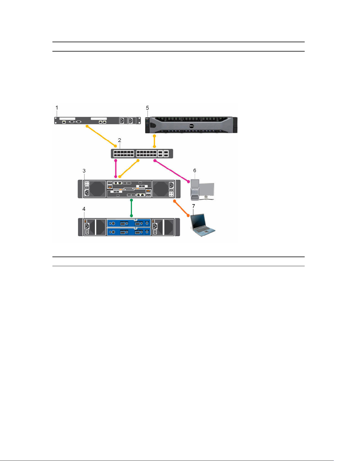
SC4020 Storage System with iSCSI Front-End Connectivity
An SC4020 storage system with iSCSI front-end connectivity may communicate with the following
components of a
Storage Center system.
Figure 5. Storage System with iSCSI Front-End Connectivity
Item Description Speed Communication Type
1 Server with Ethernet (iSCSI) ports or iSCSI
1 Gb or 10 Gb Front End
host bus adapters (HBAs)
2 Ethernet switch — A pair of Ethernet
1 Gb or 10 Gb Front End
switches is recommended for optimal
redundancy and connectivity.
3 SC4020 Storage System with iSCSI front-
1 Gb or 10 Gb Front End
end connectivity
4 SC200/SC220 Expansion Enclosures 12 Gbps per channel Back End
5 Remote Storage Center connected via iSCSI
1 Gbps or 10 Gbps Front End
for replication
6 Management network (computer connected
Up to 1 Gbps System Administration
to the storage system through the Ethernet
switch)
7 Computer connected to the SC4020
through a serial connection
115,200 Kbps System Administration
(Service and installation
only)
14
About the SC4020 Storage System
SC4020 Storage System with Front-End SAS Connectivity
An SC4020 storage system with front-end SAS connectivity may communicate with the following
components of a Storage Center system.
Figure 6. Storage System with Front-End SAS Connectivity
Item Description Speed Communication Type
1 Server with SAS host bus adapters (HBAs) 12 Gbps per channel Front End
2 Ethernet switch 1 Gbps or 10 Gbps
(Management/
Replication)
3 SC4020 Storage System with front-end SAS
connectivity
4 SC200/SC220 Expansion Enclosures 6 Gbps per channel Back End
5 Remote Storage Center connected via iSCSI
for replication
6 Management network (computer connected
to the storage system through the Ethernet
switch)
7 Computer connected to the SC4020
through a serial connection
12 Gbps per channel Front End
1 Gbps or 10 Gbps Front End
Up to 1 Gbps System Administration
115,200 Kbps System Administration
Front End
(Service and installation
only)
Back-End Connectivity
Back-end connectivity is strictly between the storage system and expansion enclosures, which hold the
physical drives that provide back-end expansion storage.
An SC4020 storage system supports back-end connectivity to multiple expansion enclosures.
About the SC4020 Storage System
15
System Administration
To perform system administration, the Storage Center communicates with computers using the Ethernet
management (MGMT) port and serial port on the storage controllers.
• Ethernet port: Used for configuration, administration, and management of Storage Center.
NOTE: The baseboard management controller (BMC) does not have a separate physical port on
the SC4020. The BMC is accessed through the same Ethernet port that is used for Storage
Center configuration, administration, and management.
• Serial port: Used for initial configuration of the storage controllers. In addition, it is used to perform
support only functions when instructed by Dell Technical Support.
NOTE: Do not throw away the serial cables that come with the SC4020. Keep the serial cables
with the SC4020 for troubleshooting purposes.
SC4020 Storage System Hardware
The SC4020 storage system ships with Dell Enterprise Plus drives, two redundant power supply/cooling
fan modules, and two redundant storage controllers.
Each storage controller contains the front-end, back-end, and management communication ports of the
storage system.
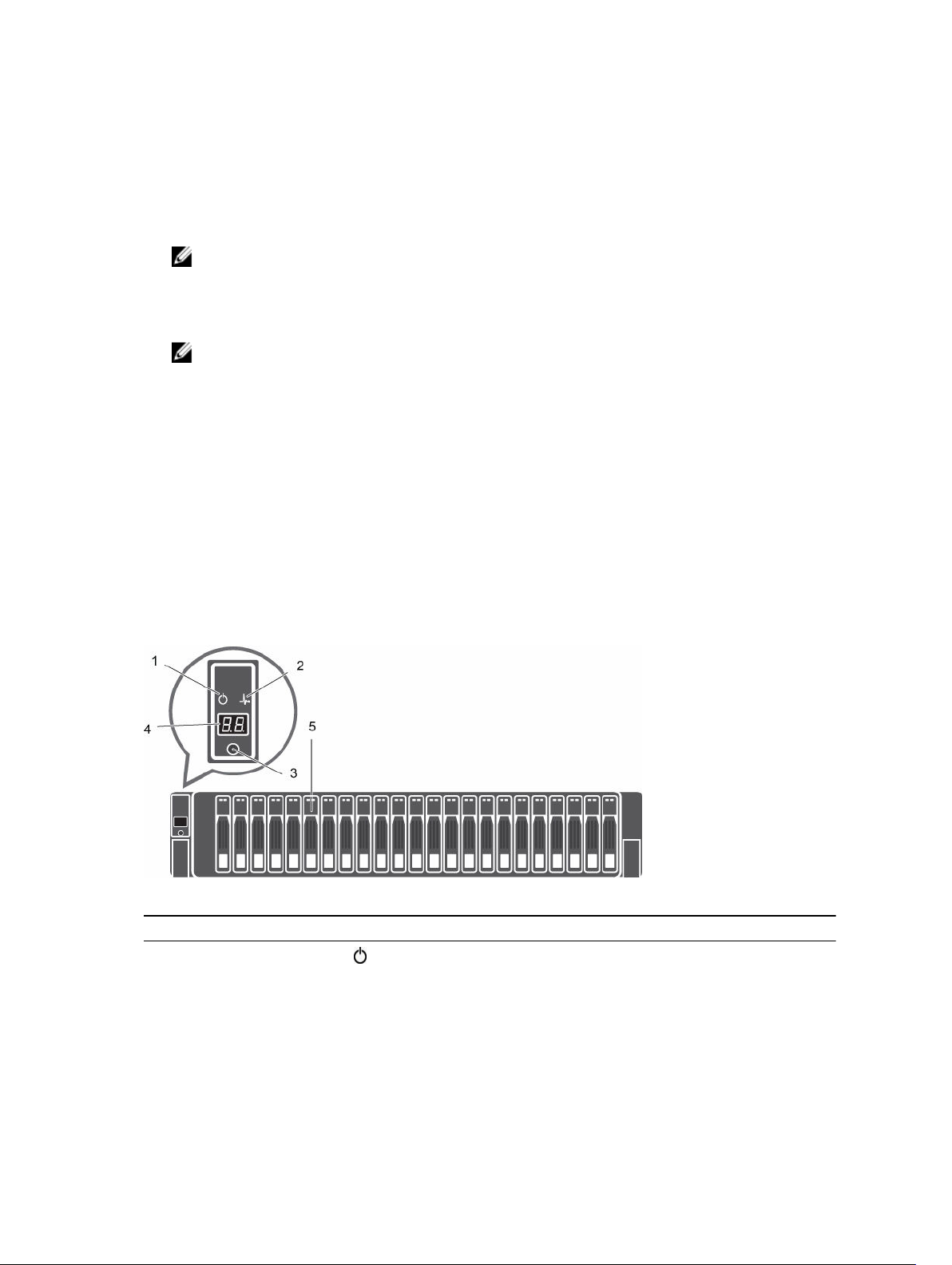
SC4020 Storage System Front-Panel Features and Indicators
The front panel of the SC4020 contains power and status indicators, a system identification button, and a
unit ID display.
In addition, the hard drives are installed and removed through the front of the storage system chassis.
Figure 7. SC4020 Storage System Front-Panel View
Item Name Icon Description
1 Power indicator Lights when the storage system power is on.
• Off: No power
16
About the SC4020 Storage System
Item Name Icon Description
• On steady green: At least one power supply is providing
power to the storage system
2 Status indicator
3 Identification
button
4 Unit ID display — Displays the storage system identification number. The default
5 Hard drives — Can have up to 24 2.5-inch SAS hard drives.
Lights when at least one power supply is supplying power to
the storage system.
• Off: No power
• On steady blue: Power is on and firmware is running
• Blinking blue: Storage system is busy booting or updating
• On steady amber: Hardware detected fault
• Blinking amber: Software detected fault
Lights when the storage system identification is enabled.
• Off: Normal status
• Blinking blue: Storage system identification enabled
value for a new storage system is 01.
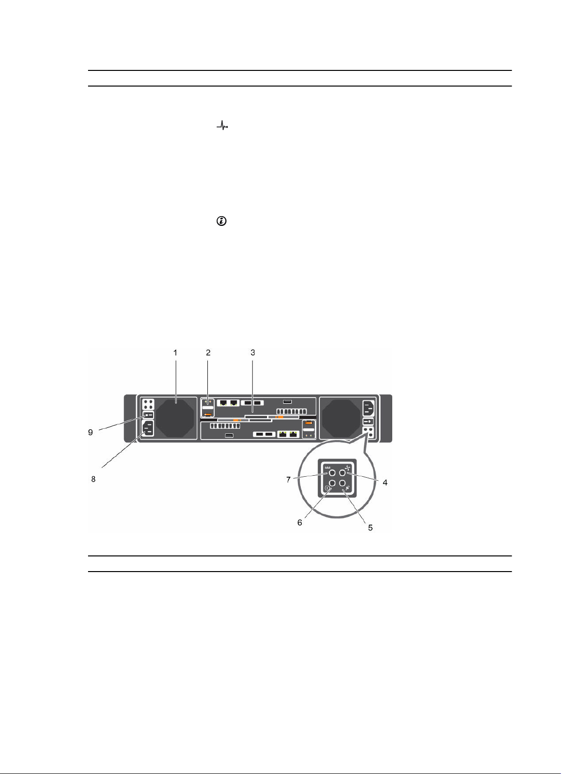
SC4020 Storage System Back-Panel Features and Indicators
The back panel of the SC4020 contains the storage controller indicators and power supply indicators.
Figure 8. SC4020 Storage System Back-Panel View
Item Name Icon Description
1 Power supply/
cooling fan module
(PSU) (2)
2 Battery backup unit
(BBU) (2)
3 Storage controller — Each storage controller contains:
About the SC4020 Storage System
— Contains a 580 W power supply and fans that provide cooling
for the storage system.
— Allows the storage controller to shut down smoothly when a
loss of AC power is detected.
• Back-end ports: Two 6 Gbps SAS ports
17

Item Name Icon Description
(2)
• Front-end ports: Fibre Channel ports, iSCSI ports, or SAS
ports
• MGMT port: Embedded Ethernet/iSCSI port that is typically
used for system management
• REPL port: Embedded iSCSI port that is typically used for
replication to another Storage Center
• Serial port: Used for initial configuration and support
functions
4 Cooling fan fault
indicator (2)
• Off: Normal operation
• Steady amber: Fan fault or the storage system is having a
problem communicating with the PSU
• Blinking amber: PSU is in programming mode
5 AC power fault
indicator (2)
• Off: Normal operation
• Steady Amber: PSU has been removed or the storage
system is having a problem communicating with the PSU
• Blinking amber: PSU is in programming mode
6 AC power status
indicator (2)
• Off: AC power is off, the power is on but the PSU is not in
the storage system, or a hardware fault is possible
• Steady green: AC power is on
• Blinking green: AC power is on and the PSU is in standby
mode
7 DC power fault
indicator (2)
• Off: Normal operation
• Steady amber: PSU has been removed, a DC or other
hardware fault has occurred, or the storage system is
having a problem communicating with the PSU
• Blinking amber: PSU is in programming mode
8 Power socket (2) — Accepts a standard computer power cord.
9 Power switch (2) — Controls power for the storage system. Each PSU has one
switch.
18
About the SC4020 Storage System
SC4020 Storage System Storage Controller Features and Indicators
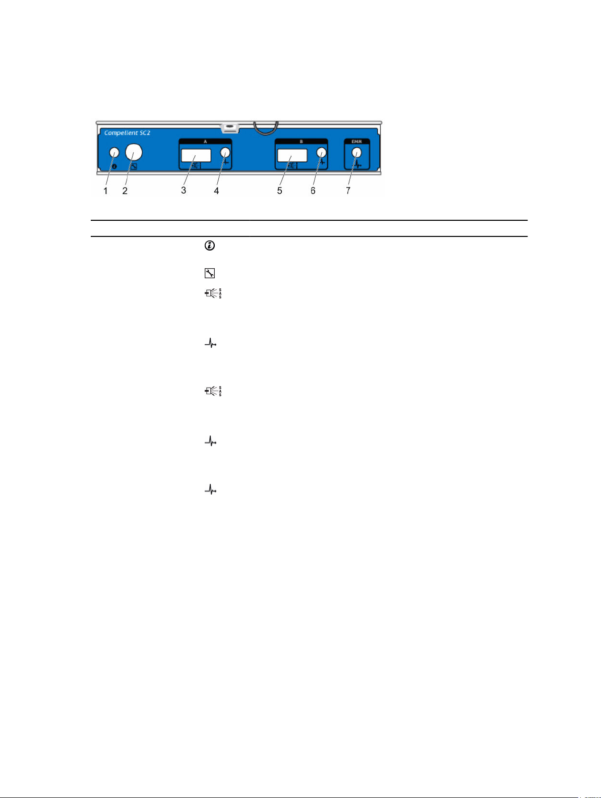
The SC4020 storage system includes two storage controllers in two interface slots.
SC4020 Storage System Storage Controller with Fibre Channel Front-End Ports
The following figures show the features and indicators on a storage controller with Fibre Channel frontend ports.
Figure 9. SC4020 Storage System Storage Controller with Four 8 Gb Fibre Channel Front-End Ports
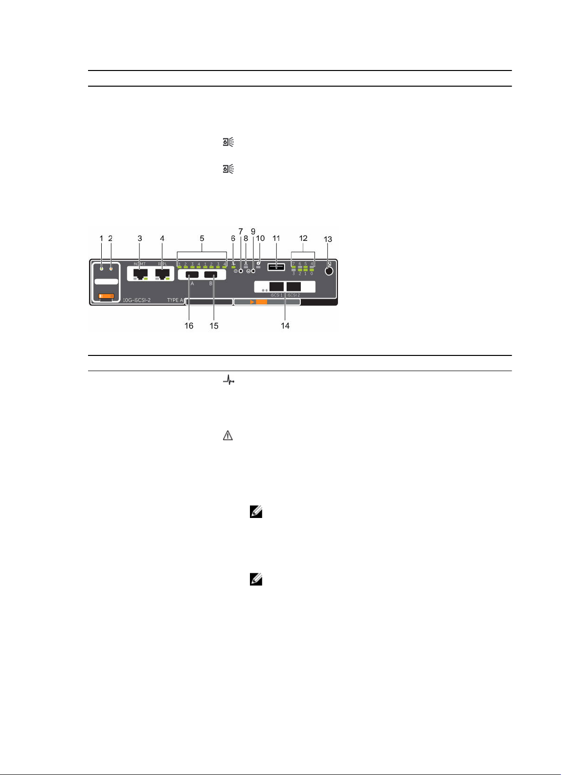
Figure 10. SC4020 Storage System Storage Controller with Two 16 Gb Fibre Channel Front-End Ports
Item Control/Feature Icon Description
1 Battery status indicator
2 Battery fault indicator
3 MGMT port (Slot 3/Port 1)— Ethernet/iSCSI port that is typically used for storage system
4 iSCSI port (Slot 3/Port 2) — Ethernet/iSCSI port that is typically used for replication to
• Blinking green (on 0.5 sec. / off 1.5 sec.): Battery heartbeat
• Fast blinking green (on 0.5 sec. / off 0.5 sec.): Battery is
charging
• Steady green: Battery is ready
• Off: No faults
• Blinking amber: Correctable fault detected
• Steady amber: Uncorrectable fault detected; replace battery
management and access to the BMC
NOTE: The MGMT port can be used as an iSCSI port for
replication to another Storage Center or as a front-end
iSCSI port for connections to host servers.
another Storage Center (requires a replication license)
About the SC4020 Storage System
19

Item Control/Feature Icon Description
NOTE: The iSCSI port can be used as a front-end port for
connections to host servers.
5 SAS activity indicators — There are four SAS PHYs per SAS port.
• Off: SAS PHY is not connected
• Steady green: SAS PHY is connected, but not active
• Blinking green: SAS PHY is not connected nor active
6 Storage controller status On: Storage controller completed POST
7 Recessed power off
Not currently used
button
8 Storage controller fault
• Off: No faults
• Steady amber: Firmware has detected an error
• Blinking amber: Storage controller is performing POST
9 Recessed reset button Not currently used
10 Identification LED
• Off: Identification disabled
• Blinking blue (for 15 sec.): Identification is enabled
• Blinking blue (continuously): Storage controller shut down
to the Advanced Configuration and Power Interface (ACPI)
S5 state
11 USB port One USB 3.0 connector
NOTE: For engineering use only.
12 Diagnostic LEDs (8) —
• Green LEDs 0–3: Low byte hex POST code
• Green LEDs 4–7: High byte hex POST code
13 Serial port (3.5 mm mini
jack)
Used to perform initial storage controller configurations. In
addition, it is used to perform support only functions when
instructed by Dell Technical Support.
14 Two options:
• Four Fibre Channel
ports (Slot 1/Port 1,
Slot 1/Port 2, Slot 1/
Port 3, and Slot 1/
Port 4) with three
LEDs per port
• Two Fibre Channel
ports (Slot 1/Port 1
and Slot 1/Port 2)
with three LEDs per
port
— LEDs for the four 8 Gb Fibre Channel ports:
• All off: No power
• All on: Booting up
• Blinking amber: 2 Gbps activity
• Blinking green: 4 Gbps activity
• Blinking yellow: 8 Gbps activity
• Blinking amber and yellow: Beacon
• All blinking (simultaneous): Firmware initialized
• All blinking (alternating): Firmware fault
LEDs for the two 16 Gb Fibre Channel ports:
• All off: No power
• All on: Booting up
• Blinking amber: 4 Gbps activity
• Blinking green: 8 Gbps activity
• Blinking yellow: 16 Gbps activity
20
About the SC4020 Storage System
Item Control/Feature Icon Description
• Blinking amber and yellow: Beacon
• All blinking (simultaneous): Firmware initialized
• All blinking (alternating): Firmware fault
15 Mini-SAS port B (Slot 2/
Back-end expansion port B
Port 2)
16 Mini-SAS port A (Slot 2/
Back-end expansion port A
Port 1)
SC4020 Storage System Storage Controller with iSCSI Front-End Ports
The following figure shows the features and indicators on a storage controller with iSCSI front-end ports.
Figure 11. SC4020 Storage System Storage Controller with Two 10 GbE iSCSI Front-End Ports
Item Control/Feature Icon Description
1 Battery status indicator
• Blinking green (on 0.5 sec. / off 1.5 sec.): Battery heartbeat
• Fast blinking green (on 0.5 sec. / off 0.5 sec.): Battery is
charging
• Steady green: Battery is ready
2 Battery fault indicator
• Off: No faults
• Blinking amber: Correctable fault detected
• Steady amber: Uncorrectable fault detected; replace battery
3 MGMT port (Slot 3/Port 1)— Ethernet/iSCSI port that is typically used for storage system
management and access to the BMC
NOTE: The MGMT port can be used as an iSCSI port for
replication to another Storage Center or as a front-end
iSCSI port for connections to host servers.
4 REPL port (Slot 3/Port 2) — Ethernet/iSCSI port that is typically used for replication to
another Storage Center
NOTE: The REPL port can be used as a front-end iSCSI port
for connections to host servers.
5 SAS activity indicators — There are four SAS PHYs per SAS port.
• Off: SAS PHY is not connected
• Steady green: SAS PHY is connected, but not active
• Blinking green: SAS PHY is not connected nor active
About the SC4020 Storage System
21
Item Control/Feature Icon Description
6 Storage controller status On: Storage controller completed POST
7 Recessed power off
Not currently used
button
8 Storage controller fault
• Off: No faults
• Steady amber: Firmware has detected an error
• Blinking amber:Storage controller is performing POST
9 Recessed reset button Not currently used
10 Identification LED
• Off: Identification disabled
• Blinking blue (for 15 sec.): Identification is enabled
• Blinking blue (continuously): Storage controller shut down
to the Advanced Configuration and Power Interface (ACPI)
S5 state
11 USB port One USB 3.0 connector
NOTE: For engineering use only.
12 Diagnostic LEDs (8) —
• Green LEDs 0–3: Low byte hex POST code
• Green LEDs 4–7: High byte hex POST code
13 Serial port (3.5 mm mini
jack)
Used to perform initial storage controller configurations. In
addition, it is used to perform support only functions when
instructed by Dell Technical Support.
14 Two iSCSI ports (Slot 1/
Port 1 and Slot 1/Port 2)
with one LED per port
—
• Off: No power
• Steady Amber: Link
• Blinking Green: Activity
15 Mini-SAS port B (Slot 2/
Back-end expansion port B
Port 2)
16 Mini-SAS port A (Slot 2/
Back-end expansion port A
Port 1)
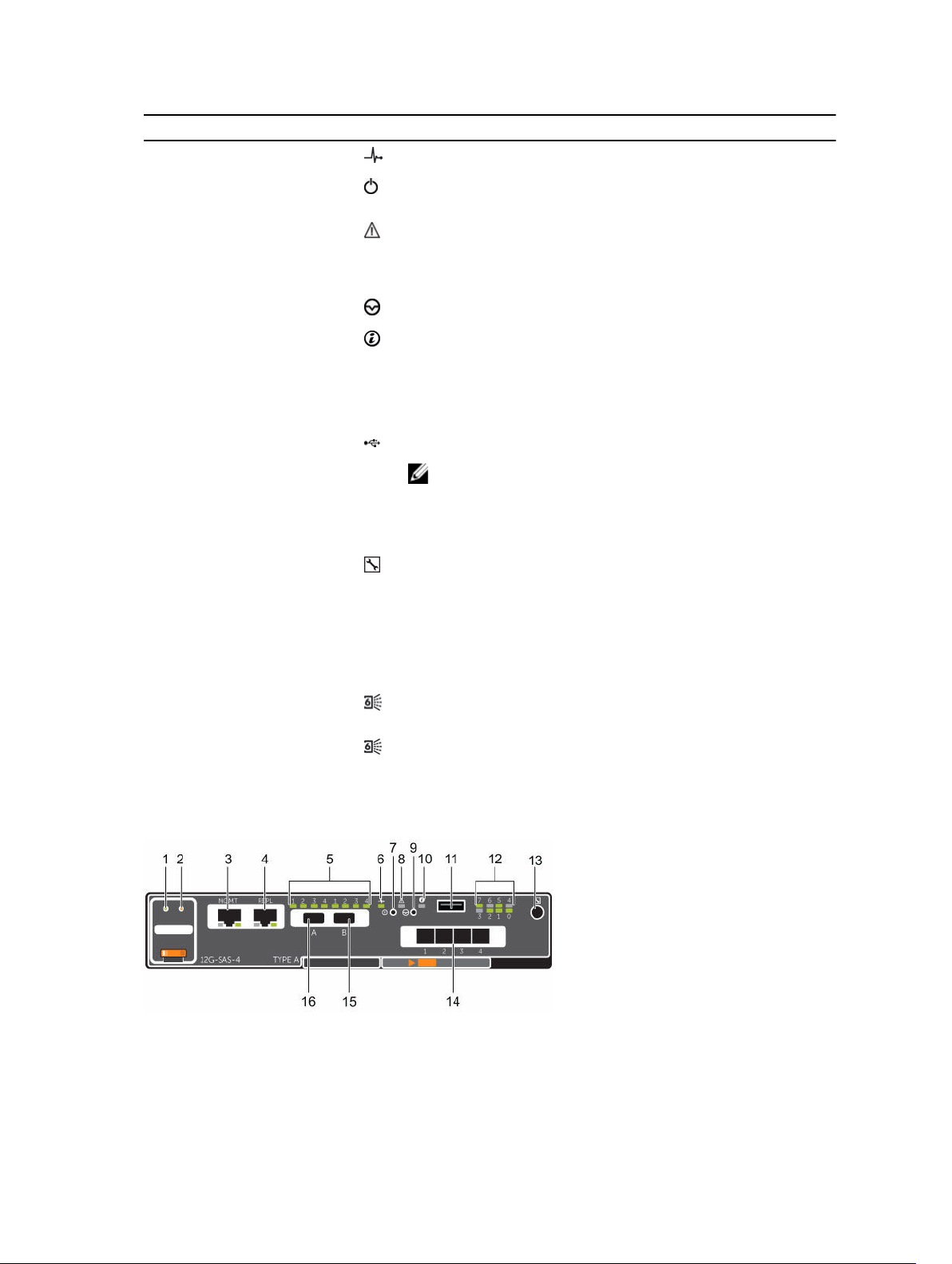
SC4020 Storage System Storage Controller with Front-End SAS Ports
The following figure shows the features and indicators on a storage controller with front-end SAS ports.
Figure 12. SC4020 Storage System Storage Controller with Four 12 Gb Front-End SAS Ports
22
About the SC4020 Storage System

Item Control/Feature Icon Description
1 Battery status indicator
• Blinking green (on 0.5 sec. / off 1.5 sec.): Battery heartbeat
• Fast blinking green (on 0.5 sec. / off 0.5 sec.): Battery is
charging
• Steady green: Battery is ready
2 Battery fault indicator
• Off: No faults
• Blinking amber: Correctable fault detected
• Steady amber: Uncorrectable fault detected; replace battery
3 MGMT port (Slot 3/Port 1)— Ethernet/iSCSI port that is typically used for storage system
management and access to the BMC
NOTE: To use the MGMT port as an iSCSI port for
replication to another Storage Center, a Flex Port license
and replication license are required. To use the MGMT port
as a front-end connection to host servers, a Flex Port
license is required.
4 REPL port (Slot 3/Port 2) — Ethernet/iSCSI port that is typically used for replication to
another Storage Center
NOTE: To use the RELP port as a front-end connection to
host servers, a Flex Port license is required.
5 SAS activity indicators — There are four SAS PHYs per SAS port.
• Off: SAS PHY is not connected
• Steady green: SAS PHY is connected, but not active
• Blinking green: SAS PHY is not connected nor active
6 Storage controller
On: Storage controller completed POST
module status
7 Recessed power off
Not currently used
button
8 Storage controller
module fault
• Off: No faults
• Steady amber: Firmware has detected an error
• Blinking amber: Storage controller is performing POST
9 Recessed reset button Not currently used
10 Identification LED
• Off: Identification disabled
• Blinking blue (for 15 sec.): Identification is enabled
• Blinking blue (continuously): Storage controller shut down
to the Advanced Configuration and Power Interface (ACPI)
S5 state
11 USB port One USB 3.0 connector
12 Diagnostic LEDs (8) —
• Green LEDs 0–3: Low byte hex POST code
• Green LEDs 4–7: High byte hex POST code
13 Serial port (3.5 mm mini
Not for customer use
jack)
About the SC4020 Storage System
23

Item Control/Feature Icon Description
14 Four Mini-SAS High
Density (HD) ports (Slot
1/Port 1, Slot 1/Port 2,
Slot 1/Port 3, and Slot 1/
Port 4)
15 Mini-SAS port B (Slot 2/
Port 2)
16 Mini-SAS port A (Slot 2/
Port 1)
— Front-end connectivity ports
NOTE: The mini-SAS HD ports are for front-end
connectivity only and cannot be used for back-end
expansion.
Back-end expansion port B
Back-end expansion port A
SC4020 Storage System Drives
The SC4020 storage system supports only Dell Enterprise Plus hard disk drives (HDDs) and Dell Enterprise
solid-state drives (eSSDs).
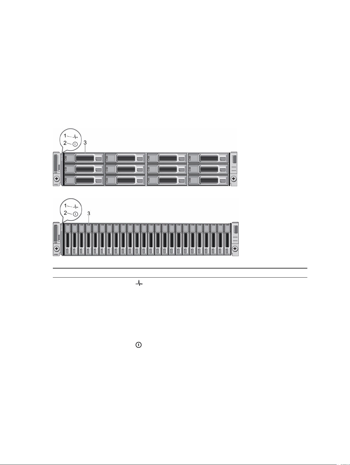
Figure 13. SC4020 Storage System Drive Indicators
Item Control/Feature Indicator Code
1 Drive activity
indicator
2 Drive status
indicator
• Blinking green: Drive activity
• Steady green: Drive is detected and has no faults
• Off: Normal operation
• Blinking amber (on 1 sec. / off 1 sec.): Drive identification is enabled
• Blinking amber (on 2 sec. / off 1 sec.): Hardware/firmware fault
• Steady amber: Drive is safe to remove
SC4020 Storage System Drive Numbering
Drives are numbered from left to right in the SC4020 storage system.
The Storage Center identifies drives as XX-YY, where XX is the unit ID of the storage system, and YY is the
drive position inside the
The SC4020 holds up to 24 drives, which are numbered from left to right starting from 0.
Figure 14. SC4020 Storage Systems Drive Numbering
storage system.
24
About the SC4020 Storage System
SC200/SC220 Expansion Enclosure Overview
The SC200 is a 2U expansion enclosure that supports up to 12 3.5‐inch hard drives installed in a four‐
column, three-row configuration. The SC220 is a 2U expansion enclosure that supports up to 24 2.5‐inch
hard drives installed vertically side by side.
An SC200/SC220 expansion enclosure ships with two redundant power supply/cooling fan modules and
two redundant enclosure management modules (EMMs).
SC200/SC220 Expansion Enclosure Front-Panel Features and Indicators
The SC200/SC220 front panel shows the expansion enclosure status and power supply status.
Figure 15. SC200 Front-Panel Features and Indicators
Figure 16. SC220 Front-Panel Features and Indicators
Item Name Icon Description
1 Expansion enclosure
status indicator
2 Power supply status
indicator
3 Hard drives — Dell Enterprise Plus Drives
About the SC4020 Storage System
Lights when the expansion enclosure power is on.
• Off: No power
• On steady blue: Normal operation
• Blinking blue: Storage Center is identifying the
expansion enclosure
• On steady amber: Expansion enclosure is turning on or
was reset
• Blinking amber: Expansion enclosure is in the fault state
Lights when at least one power supply is supplying power
to the expansion enclosure.
• Off: Both power supplies are off
• On steady green: At least one power supply is providing
power to the expansion enclosure
• SC200: Up to 12 3.5-inch hard drives
25
Item Name Icon Description
• SC220: Up to 24 2.5-inch hard drives
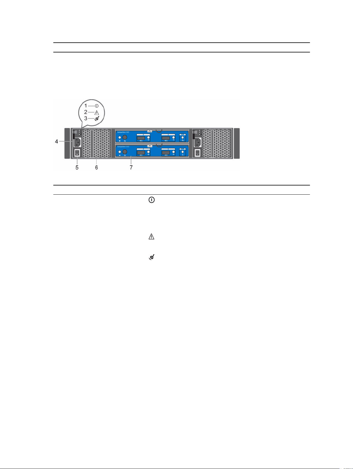
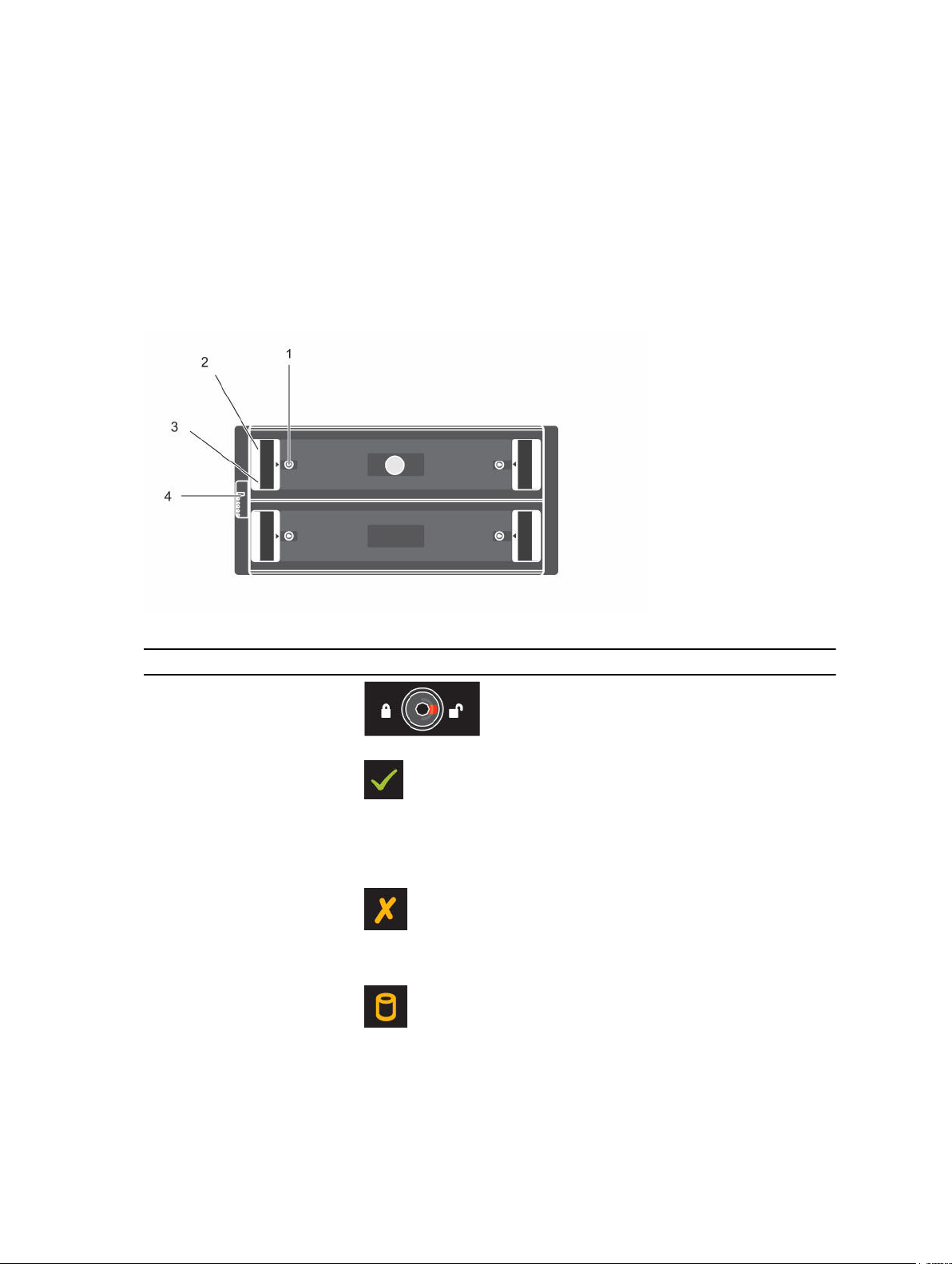
SC200/SC220 Expansion Enclosure Back-Panel Features and Indicators
The SC200/SC220 back panel provides controls to power up and reset the expansion enclosure,
indicators to show the expansion enclosure status, and connections for back-end cabling.
Figure 17. SC200/SC220 Expansion Enclosure Back Panel Features and Indicators
Item Name Icon Description
1 DC power indicator
• Green: Normal operation. The power supply
module is supplying DC power to the expansion
enclosure
• Off: Power switch is off, the power supply is not
connected to AC power, or has a fault condition
2 Power supply/cooling fan
indicator
3 AC power indicator
4 Power socket (2) — Accepts a standard computer power cord.
5 Power switch (2) — Controls power for the expansion enclosure. Each
6 Power supply/cooling fan
module (2)
7 Enclosure management
module (2)
— Contains a 700 W power supply and fans that provide
— EMMs provide the data path and management
• Amber: Power supply/cooling fan fault is detected
• Off: Normal operation
• Green: Power supply module is connected to a
source of AC power, whether the power switch is
on
• Off: Power supply module is disconnected from a
source of AC power
power supply/cooling fan module has one switch.
cooling for the expansion enclosure.
functions for the expansion enclosure.
26
About the SC4020 Storage System
SC200/SC220 Expansion Enclosure EMM Features and Indicators
The SC200/SC220 includes two enclosure management modules (EMMs) in two interface slots.
Figure 18. SC200/SC220 Expansion Enclosure EMM Features and Indicators
Item Name Icon Description
1 System status
indicator
2 Serial port Not for customer use.
3 SAS port A (in) Connects to a storage controller or to other SC200/SC220
4 Port A link
status
Not used on SC200/SC220 expansion enclosures.
expansion enclosures. SAS ports A and B can be used for either
input or output. However, for cabling consistency, use port A as
an input port.
• Green: All the links to the port are connected
• Amber: One or more links are not connected
• Off: Expansion enclosure is not connected
5 SAS port B
(out)
6 Port B link
status
7 EMM status
indicator
Connects to a storage controller or to other SC200/SC220
expansion enclosures. SAS ports A and B can be used for either
input or output. However, for cabling consistency, use port B as
an output port.
• Green: All the links to the port are connected
• Amber: One or more links are not connected
• Off: Expansion enclosure is not connected
• On steady green: Normal operation
• Amber: Expansion enclosure did not boot or is not properly
configured
• Blinking green: Automatic update in progress
• Blinking amber (two times per sequence): Expansion
enclosure is unable to communicate with other expansion
enclosures
• Blinking amber (four times per sequence): Firmware update
failed
• Blinking amber (five times per sequence): Firmware versions
are different between the two EMMs
About the SC4020 Storage System
27
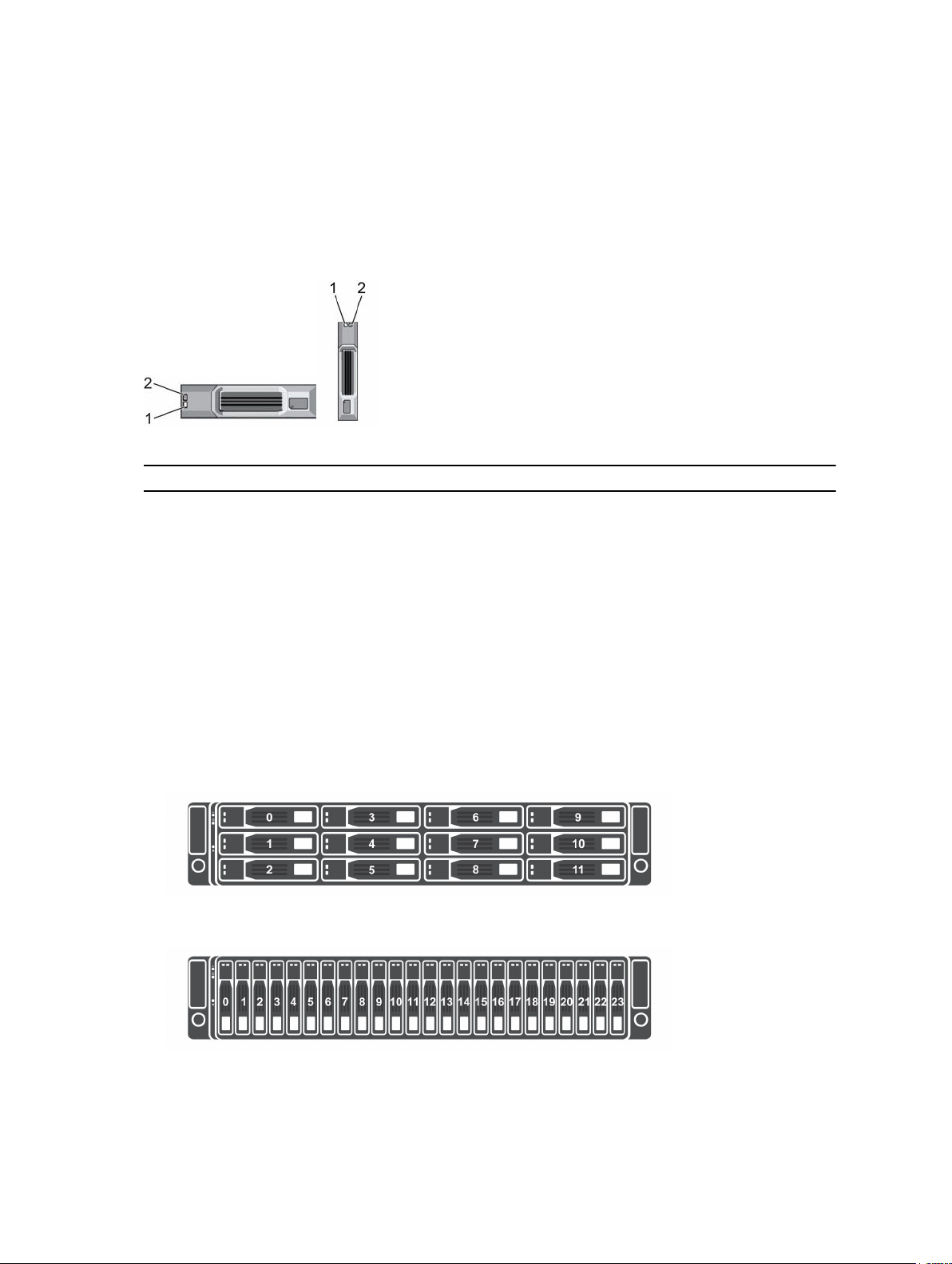
SC200/SC220 Expansion Enclosure Drives
Dell Enterprise Plus hard disk drives (HDDs) and Dell Enterprise Plus solid-state drives (SSDs) are the only
drives that can be installed in SC200/SC220 expansion enclosures. If a non-Dell Enterprise Plus drive is
installed, the
The drives in an SC200 expansion enclosure are installed horizontally. The drives in an SC220 expansion
enclosure are installed vertically. The indicators on the drives provide status and activity information.
Figure 19. SC200/SC220 Expansion Enclosure Drive Indicators
Item Name Indicator Code
1 Drive activity
Storage Center prevents the drive from being managed.
• Blinking green: Drive activity
indicator
• Steady green: Drive is detected and there are no faults
2 Drive status
indicator
• Steady green: Normal operation
• Blinking green (on 1 sec. / off 1 sec.): Drive identification is enabled
• Steady amber: Drive is safe to remove
• Off: No power to the drive
SC200/SC220 Expansion Enclosure Drive Numbering
In an SC200/SC220 expansion enclosure, the drives are numbered from left to right starting from 0.
The Storage Center identifies drives as XX-YY, where XX is the unit ID of the expansion enclosure that
contains the drive, and YY is the drive position inside the expansion enclosure.
• An SC200 holds up to 12 drives, which are numbered in rows starting from 0 at the top-left drive.
Figure 20. SC200 Expansion Enclosure Drive Numbering
• An SC220 holds up to 24 drives, which are numbered left to right starting from 0.
Figure 21. SC220 Expansion Enclosure Drive Numbering
28
About the SC4020 Storage System
SC280 Expansion Enclosure Overview
The SC280 is a 5U SAS expansion enclosure that supports up to 84 internal 3.5‐inch hard drives installed
in a two‐drawer, three‐row, 14‐column configuration.
The SC280 expansion enclosure ships with two redundant power supply units, five redundant cooling
fans, and two redundant enclosure management modules (EMMs).
SC280 Expansion Enclosure Front-Panel Features and Indicators
The SC280 front panel displays the expansion enclosure status.
Figure 22. SC280 Expansion Enclosure Front-Panel Features and Indicators
Item Name Panel Description
1 Drawer-specific
anti-tamper locks
2 Drawer-specific
left and right side
status indicators
Locks the drawer shut using a Torx T20
screwdriver until the red arrows point to the
locked icon (away from the center of the
chassis).
• Sideplane OK/Power Good
– Off — Sideplane card or cable fault
– Green — Sideplane card and cable are
functional (though a fault may be
indicated by one or more of the
following LEDs)
• Drawer Fault
– Amber — Sideplane card fault or drive
failure causing loss of availability or
redundancy
• Logical Fault
– Amber (steady) — Host indicated drive
fault
About the SC4020 Storage System
29

Item Name Panel Description
– Amber (flashing) — Arrays in impacted
state
• Cable Fault
– Amber — Cable fault
3 Drawer-specific
left and right side
expansion
enclosure activity
indicators
4 Status indicator
for storage
system
Activity Bar Graph — Six variable-intensity
LEDs dynamically displaying access of the
drives in that specific drawer
• Unit ID Display — Numerical display
primarily used to display the unit
identification number
• Input Switch — Not used
• Power On/Standby
– Off — Expansion enclosure does not
have power
– Green — Expansion enclosure is on
(operational)
– Amber — Expansion enclosure is in
standby mode (not operational)
• Module Fault
– Amber — Hardware fault (an LED may
be lit on a PSU, drawer, DDIC, fan
module, or I/O module indicating the
part at fault)
30
• Logical Status:
– Amber — Change of status or fault from
something other than the storage
system itself (this status is typically
associated with a disk drive as indicated
by its own fault LED)
• Drawer 1 Fault
– Amber — Drive, cable, or sideplane fault
has occurred in drawer 1
• Drawer 2 Fault
– Amber — Drive, cable, or sideplane fault
has occurred in drawer 2
About the SC4020 Storage System
 Loading...