

Dell S6100 Installation Manual

Dell Installation Guide for the S6100–ON System
June 2017

Notes, cautions, and warnings
NOTE: A NOTE indicates important information that helps you make better use of your computer.
CAUTION: A CAUTION indicates either potential damage to hardware or loss of data and tells you how to avoid the problem.
WARNING: A WARNING indicates a potential for property damage, personal injury, or death.
Copyright © 2017 Dell Inc. or its subsidiaries. All rights reserved. Dell, EMC, and other trademarks are trademarks of Dell Inc. or its subsidiaries. Other
trademarks may be trademarks of their respective owners.
2017 - 06
Rev. A04

Contents
1 About this guide............................................................................................................................................. 5
Notices................................................................................................................................................................................ 5
Related documents............................................................................................................................................................5
2 S6100–ON system.........................................................................................................................................6
Introduction.........................................................................................................................................................................6
Features...............................................................................................................................................................................7
Physical dimensions........................................................................................................................................................... 8
Luggage tag........................................................................................................................................................................8
System status.....................................................................................................................................................................9
LED display..........................................................................................................................................................................9
LED behavior ............................................................................................................................................................... 9
Prerequisites.......................................................................................................................................................................11
S6100–ON congurations............................................................................................................................................... 12
3 Site preparations.......................................................................................................................................... 13
Site selection..................................................................................................................................................................... 13
Cabinet placement............................................................................................................................................................13
Rack mounting.................................................................................................................................................................. 14
System ground..................................................................................................................................................................14
Fans and airow................................................................................................................................................................14
Fan combinations........................................................................................................................................................14
Power.................................................................................................................................................................................14
Storing components.........................................................................................................................................................15
4 NEBS compliance.........................................................................................................................................16
Important information...................................................................................................................................................... 16
NEBS-compliant ground installation...............................................................................................................................16
For rack spans from 22 to 23.375 inches.................................................................................................................17
For rack spans from 23.375 to 36 inches................................................................................................................ 19
5 S6100–ON installation................................................................................................................................. 23
Installation overview........................................................................................................................................................ 23
Unpack the S6100-ON System......................................................................................................................................23
Four-post rack assembly.................................................................................................................................................24
Four-post rack mount......................................................................................................................................................24
Chassis ground.................................................................................................................................................................25
I/O module installation.....................................................................................................................................................27
Important points.........................................................................................................................................................28
SFP+ and QSFP optics installation................................................................................................................................29
SFP+ and QSFP optics removal.....................................................................................................................................29
Port connectivity..............................................................................................................................................................29
Contents
3

System power-up..............................................................................................................................................................31
Power up sequence....................................................................................................................................................31
6 Power supplies.............................................................................................................................................33
Components..................................................................................................................................................................... 33
AC or DC power supply installation................................................................................................................................34
DC power supply connection................................................................................................................................... 35
AC or DC power supply replacement.............................................................................................................................37
7 Fans.............................................................................................................................................................38
Components..................................................................................................................................................................... 38
Fan module installation....................................................................................................................................................39
Fan module replacement.................................................................................................................................................40
Fan air lter replacement................................................................................................................................................ 40
After system installation...................................................................................................................................................41
8 Management ports...................................................................................................................................... 42
RS-232 console port access...........................................................................................................................................42
Accessing the RJ-45 Console Port with a DB-9 Adapter.....................................................................................43
Micro USB-B console port access.................................................................................................................................43
USB storage......................................................................................................................................................................44
Before you install an OS.................................................................................................................................................. 44
Grub bootloader exampleONIE example.................................................................................................................45
ONIE service discovery...................................................................................................................................................45
9 Dell support................................................................................................................................................. 47
10 Specications............................................................................................................................................ 49
Chassis physical design................................................................................................................................................... 49
IEEE standards.................................................................................................................................................................50
Agency compliance...........................................................................................................................................................51
USA Federal Communications Commission (FCC) statement....................................................................................51
European Union EMC Directive Conformance statement...........................................................................................51
Japan: VCCI Compliance for Class A Equipment.........................................................................................................52
Korean Certication of Compliance...............................................................................................................................52
Safety Standards and Compliance Agency Certications.......................................................................................... 53
Electromagnetic Compatibility (EMC).......................................................................................................................... 53
EmissionsImmunity.................................................................................................................................................... 53
Product recycling and disposal.......................................................................................................................................54
Waste Electrical and Electronic Equipment (WEEE) directive for recovery, recycle and reuse of IT and
telecommunications products.................................................................................................................................. 54
Contents
4
About this guide
This guide provides site preparation recommendations, step-by-step procedures for rack mounting and desk mounting, inserting optional
modules, and connecting to a power source.
Notices
CAUTION: To avoid electrostatic discharge (ESD) damage, wear grounding wrist straps when handling this equipment.
WARNING: Only trained and qualied personnel can install this equipment. Read this guide before you install and power up this
equipment. This equipment contains two power cords. Disconnect both power cords before servicing.
WARNING: This equipment contains optical transceivers, which comply with the limits of Class 1 laser radiation.
1
Figure 1. Class 1 Laser Product Tag
WARNING: When no cable is connected, visible and invisible laser radiation may be emitted from the aperture of the optical
transceiver ports. Avoid exposure to laser radiation and do not stare into open apertures.
Related documents
For more information about the S6100–ON system, see the following documents:
• Dell Getting Started Guide for the S6100–ON System
• Dell Release Notes for the S6100–ON System
• Open Networking (ON) Hardware Diagnostic Guide
• Dell Command Line Reference Guide for the S6100–ON System
• Dell Conguration Guide for the S6100–ON System
NOTE
: For the most recent documentation, visit Dell Support: www.dell.com/support.
About this guide 5

2
S6100–ON system
The following sections describe the Dell S6100–ON system:
Topics:
• Introduction
• Features
• Physical dimensions
• Luggage tag
• System status
• LED display
• Prerequisites
• S6100–ON congurations
Introduction
S6100-ON is a two rack unit 10/25/40/100 GbE switch. A fully loaded system includes 64 quad form-factor pluggable (QSFP+ or QSFP28)
optics for 40/100 GbE aggregation and 10/25/40/100 GbE top of rack (ToR) and end of row (EoR) applications. The S6100–ON system
includes two hot-swappable AC or DC power supply units (PSUs) and four hot-swappable fan units.
The S6100–ON supports three types of I/O modules:
• 16 x 40 GbE QSFP+
• Top row of ports can operate as:
• Single 40G port
• Quad 10G ports
NOTE
: If you congure port [n] as a quad 10G port, port [n + 1] will not be
available
• 8 x 100 GbE QSFP28
• Each port can operate as:
• Single 100G port
• Single 40G port
• Quad 25G ports
• Quad 10G ports
• 4 x QSFP28 + 4 x CXP
• Each QSFP28 port can operate as:
• Single 100G port
• Single 40G port
• Quad 25G ports
• Quad 10G ports
• Each CXP port can operate as:
• Single 100G port
All 100 GbE (QSFP28) ports support 4 x 25 GbE.
6 S6100–ON system
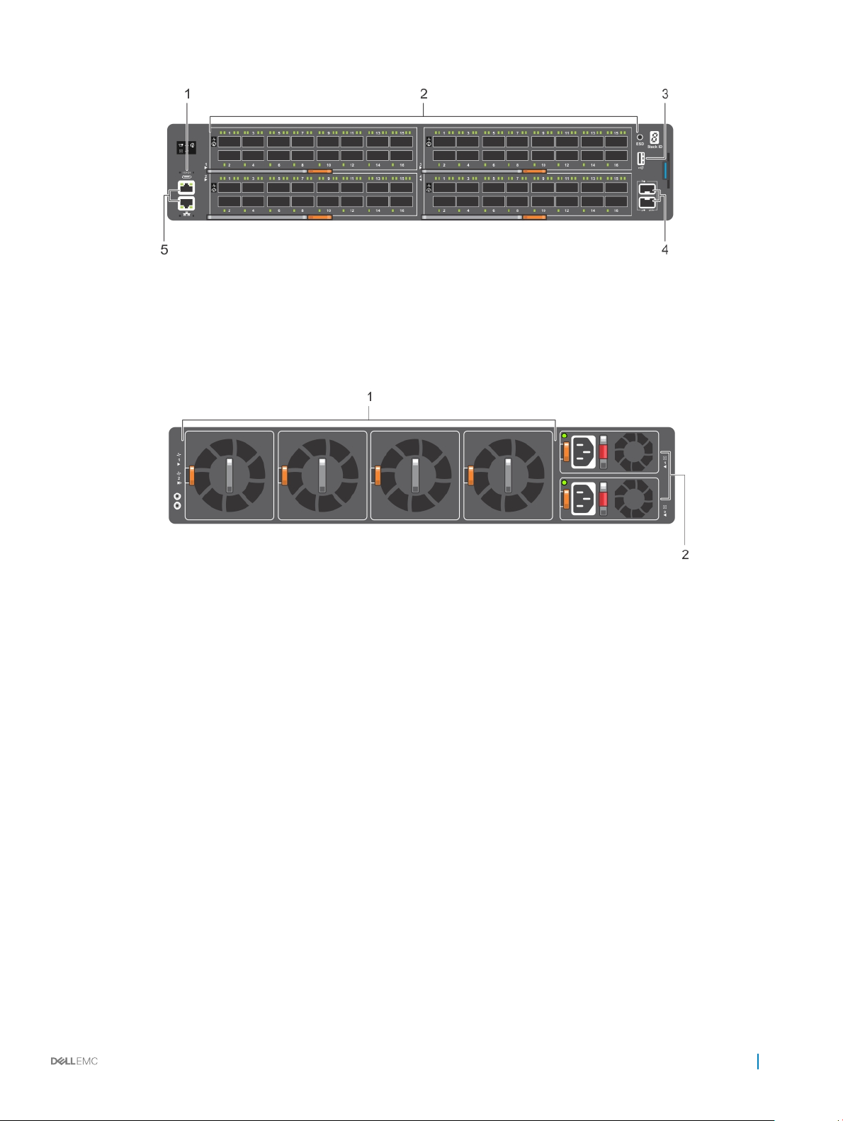
Figure 2. S6100–ON I/O-side view
1 MicroUSB-B port 2 64 x 10/40 QSFP+ or 32 x 10/25/40/100 QSFP28
3 USB Type A 4 SFP+ ports
5 Top: RJ-45 console port. Bottom: RJ-45 management port
Figure 3. S6100–ON PSU-side view
1
Fan modules 2 Power supply units
Features
The S6100–ON oers the following features:
• Up to four I/O modules of 8 x 10/25/40/50/100 GbE QSFP28 ports
• Up to four I/O modules of 16 x 10/40 GbE QSFP+ ports
• Up to four I/O modules of 4 x 10/25/40/50/100 GbE QSFP28 ports and 4 x 100 GbE CXP ports
• Up to one hundred twenty-eight 10G ports
• Up to one hundred twenty-eight 25G ports
• Up to sixty-four 40G ports
• Up to sixty-four 50G ports
• Up to thirty-two 100G ports
• Two SFP+ ports
• One micro universal serial bus (MicroUSB-B) console port, optional
• One 2.0 USB Type-A port for additional le storage
• One 10/100/1000BaseT Ethernet management port
• Rangeley central processing unit (CPU) system with 8GB DDR III RAM.
• Temperature monitoring
• Software-readable thermal monitor
S6100–ON system
7
• Real time clock (RTC) support
• Hot-pluggable redundant power supplies
• Power management monitoring
• Four hot-pluggable replaceable fan modules
• Standard 2U chassis
• Two-hole ground lug
Physical dimensions
The S6100-ON has the following physical dimensions:
• 442 x 510 x 86.75 mm (W x D x H)
• 17.40 x 20 x 3.41 inches (W x D x H)
Luggage tag
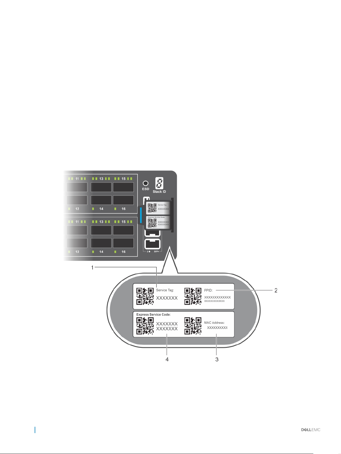
The S6100–ON system has a pull-out tag, known as a luggage tag, on the I/O-side of the system.
Figure 4. S6100–ON luggage tag
Service tag 2 PPID
1
8 S6100–ON system
3 MAC address 4 Express service code
System status
You can view S6100–ON status information using the LEDs.
LED display
The S6100–ON includes LED displays on the I/O side of the system.
NOTE: If you are installing third-party software, for LED information, see your third-party operating software documentation.
LED behavior
The following S6100–ON system LED behavior is seen during open networking installation environment (ONIE) operations:
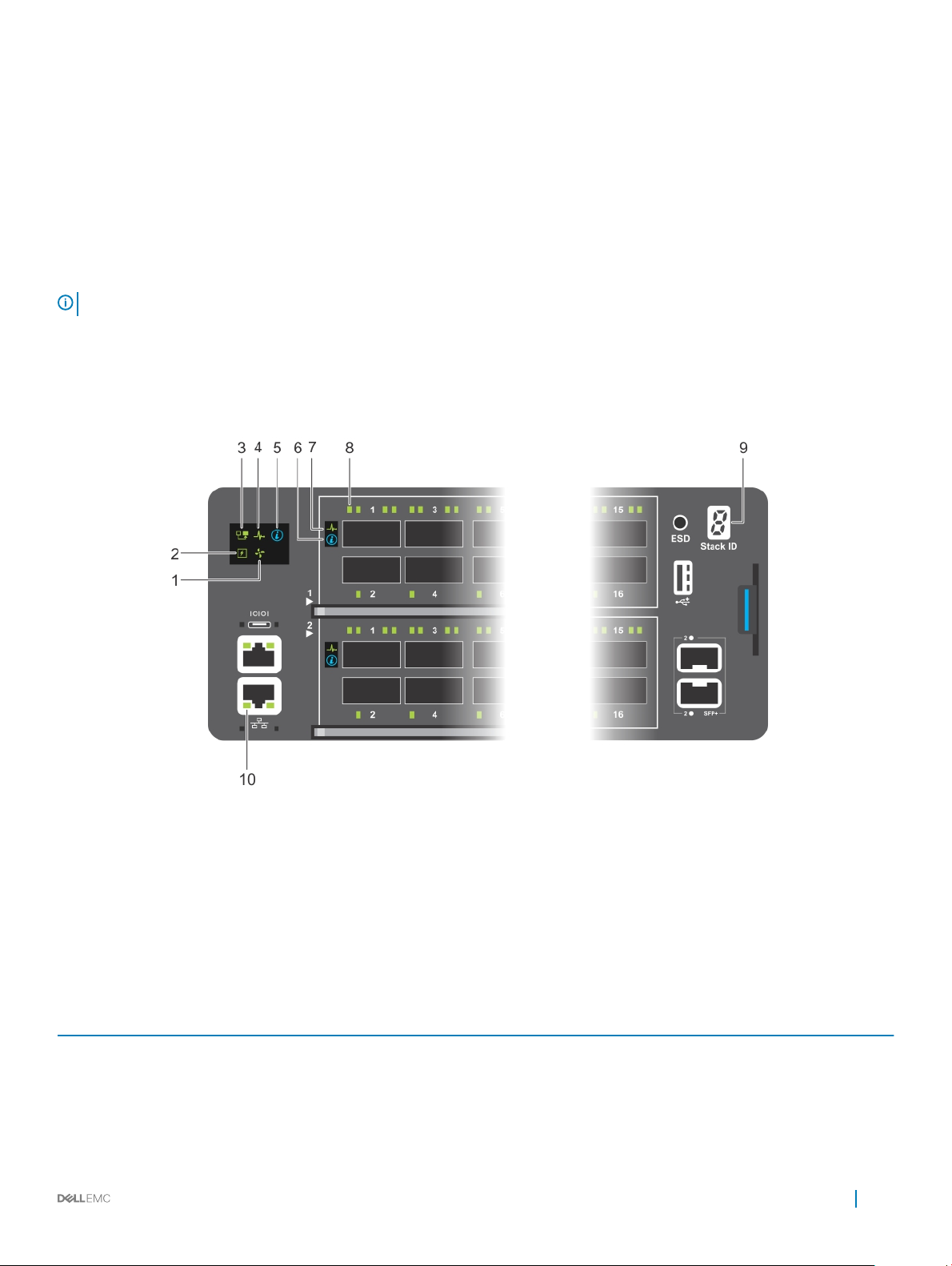
Figure 5. S6100–ON LEDs
1
Fan LED 2 Power LED
3 Master LED 4 System LED
5 Locator LED 6 Locator LED
7 System LED 8 Port LEDs
9 Stack ID LED 10 RJ-45 Ethernet Management Port LED
Table 1. S6100–ON LED behavior
LED Description
System Status and Health LED
• O—No power
• Solid green—Normal Operation
• Blinking green—POST is in process
• Solid amber—Critical system error
S6100–ON system 9

LED Description
• Blinking amber—Minor system error
Power LED
Master LED
Management LED
FAN LED
LOCATOR LED
• O—No power
• Solid green—Normal Operation
• Solid amber—POST is in process
• Blinking amber—Noncritical system error—power supply failure
• O—Switch is in Stacking Slave mode
• Solid green—System is in Stacking Master or Standalone mode
• O—No Link
• Solid green—Link on 1 Gbps speed
• Solid amber—Link on 10/100 Mbps speeds
• Blinking green—Port activity
• O—No power
• Solid green—fan powered and running at the expected RPM
• Blinking amber—fan failed, including incompatible airow
direction when you insert the PSU or fan trays with diering
airows
• O—Locator is idle
• Blinking blue—Locator is functioning
Table 2. QSFP28 port LEDs
LED Description
Link LED
Activity LED
Table 3. QSFP28 port LEDs—4x25 GbE or 4x10 GbE Mode
LED Description
Link LED
Activity LED
• O—No Link
• Solid green—Port activity operating at maximum port speed
• Solid amber—Port activity operating at lower speed
• O—No Link
• Flashing green, ~30 ms—port activity operating at maximum
port speed
• Flashing amber, ~30 ms—port activity operating at lower port
speed
• O—No Link
• Solid green—Port link is 4x25 GbE
• Solid amber—Port link is 4x10 GbE
• O—No Link
• Flashing green, ~30 ms—Port link is 4x25 GbE
10 S6100–ON system

LED Description
• Flashing amber, ~30 ms—Port link is 4x10 GbE
Table 4. QSFP28 Port LEDs—2x40GbE Mode
LED Description
Link LED
Activity LED
Table 5. SFP+ port LEDs
LED Description
Link LED
Activity LED
• O—No Link
• Solid green—Port link is 2x40 GbE
• O—No Link
• Flashing amber, ~30 ms—Port link is 2x40 GbE
• O—No Link
• Solid green—Port activity operating at maximum port speed
• Solid amber—Port activity operating at lower speed
• O—No Link
• Flashing green, ~30 ms—port activity operating at maximum
port speed
• Flashing amber, ~30 ms—port activity operating at lower port
speed
Prerequisites
The following is a list of components required for successful installation of the S6100-ON:
NOTE
: Detailed installation instructions for the S6100-ON are provided in Site preparations and S6100-ON Installation.
• S6100–ON chassis or multiple chassis, if stacking
• AC or DC country and regional-specic cables to connect the AC or DC power source to each of the chassis’ AC or DC power supplies
• Mounting brackets for rack installation, included
• Screws for rack installation
• #1 and #2 Phillips screw drivers, not included
• Torx screwdriver, not included
• Ground cable screws, included
• Copper or ber cables
Other optional components are:
• Ground cable
• Extra power supply unit
• Extra fan module
• Extra mounting brackets
S6100–ON system
11

S6100–ON congurations
You can order the S6100–ON system in several dierent congurations.
• S6100–ON AC or DC Normal Airow: thirty–two 10/25/40/100 GbE ports with four SFP+ 10 GbE ports, two AC or DC power supply
units and four fan subsystems. Fan airow is from the I/O side to the power supply side.
• S6100–ON AC or DC Reverse Airow: thirty–two 10/25/40/100 GbE ports with four SFP+ 10 GbE ports, two AC or DC power supply
units and four fan subsystems. Fan airow is from the I/O side to the power supply side.
• Fan with airow from the I/O side to the PSU side.
• Fan with airow from the PSU side to the I/O side.
• AC or DC power supply with airow from the I/O side to the PSU side.
• AC or DC power supply with airow from the PSU side to the I/O side.
The S6100–ON oers three types of I/O modules:
• 16 x 40 GbE QSFP+
• 8 x 100 GbE QSFP28
• 4 x QSFP28 + 4 x CXP
12 S6100–ON system

The S6100–ON is suitable for installation as part of a common bond network (CBN).
You can install the system in:
• Network telecommunication facilities
• Data centers
• Other locations where the National Electric Code (NEC) applies
For more information about S6100–ON specications, see Specications.
NOTE: Install the S6100–ON system into a rack before installing any optional components.
Topics:
• Site selection
• Cabinet placement
• Rack mounting
• System ground
• Fans and airow
• Power
• Storing components
3
Site preparations
Site selection
Install Dell equipment in restricted access areas.
A restricted access area is one in which service personnel can only gain access using a special tool, lock, key or other means of security.
Access is controlled by the authority responsible for the location.
Ensure that the area where you install your S6100–ON system meets the following safety requirements:
• Near an adequate power source. Connect the system to the appropriate branch circuit protection as dened by your local electrical
codes.
• Environmental temperature range is from 32° to 113°F (from 0° to 45°C).
• The switch operating ambient temperature range is from 10° to 35°C (from 50° to 95°F).
• Relative humidity is from 5 to 85 percent noncondensing.
• In a dry, clean, well-ventilated and temperature-controlled room, away from heat sources such as hot air vents or direct sunlight.
• Away from sources of severe electromagnetic noise.
• Positioned in a rack or cabinet, or on a desktop with adequate space in the front, back, and sides for proper ventilation and access.
Cabinet placement
Install the S6100–ON only in indoor cabinets designed for use in a controlled environment.
Do not install the S6100–ON in outside cabinets. For cabinet placement requirements, see Site selection.
Site preparations 13

The cabinet must meet minimum size requirements. Airow must be in accordance with the Electronic Industries Alliance (EIA) standard.
Ensure that there is a minimum of 5 inches (12.7 cm) between the intake and exhaust vents and the cabinet wall.
Rack mounting
When you prepare your equipment rack, ensure that the rack is grounded.
Ground the equipment rack to the same ground point the power service in your area uses. The ground path must be permanent.
System ground
Dell recommends grounding your system. Use the S6100–ON in a common bond network (CBN).
Connect the grounding cables as described in S6100-ON installation.
Fans and airow
The S6100–ON fans support two airow options: normal and reverse.
Fan combinations
The S6100-ON has stock keeping units (SKUs) that support the following congurations. Installation of the fans is done as part of the
factory install based on SKU type.
• AC or DC PSU with fan airow from the I/O to the PSU
• AC or DC PSU with fan airow from the PSU to the I/O
Be sure to order the fans suitable to support your site’s ventilation. Use a single type of airow fan in your system. Do not mix reverse and
normal airows in a single S6100–ON chassis.
For proper ventilation, position the S6100-ON in an equipment rack or cabinet with a minimum of 5 inches (12.7 cm) of clearance around
the exhaust vents. When you install two S6100-ON systems near each other, to permit proper airow, position the two chassis at least 5
inches (12.7 cm) apart. The fan speed increases when the internal temperature reaches 161.6°F (72°C). The fan speed decreases to normal
speed when the temperature falls to 136.4°F (58°C). The S6100-ON never intentionally turns o the fans.
Power
To connect the chassis to the applicable power source, use the appropriate power cord with the S6100–ON. An AC or DC power cord is
included with the system.
When installing AC or DC systems, follow the requirements of the National Electrical Code, ANSI/NFPA 70 where applicable.
CAUTION
CAUTION: Use the power supply cord as the main disconnect device on the AC system. Ensure that the socket-outlet is located
and installed near the equipment and is easily accessible.
The system is powered-up when the power cord is connected between the system and the power source.
NOTE
: Always disconnect the power cable before you service the power supply slots.
: Module power is software controlled. You do not see module LEDs when the system powers up in ONIE.
14 Site preparations

Storing components
If you do not install your S6100–ON and components immediately, properly store the system and all optional components by following these
guidelines:
• Storage location temperature must remain constant. The storage range is from -40° to 158°F (-40°C to 70°C).
• Store on a dry surface or oor, away from direct sunlight, heat, and air conditioning ducts.
• Store in a dust-free environment.
NOTE: ESD damage can occur when components are mishandled. Always wear an ESD-preventive wrist or heel ground strap
when handling the S6100–ON and its accessories. After you remove the original packaging, place the S6100–ON and its
components on an anti-static surface.
Site preparations 15
NEBS compliance
For your system to be network equipment building system (NEBS) compliant, you must follow the instructions detailed in this chapter.
To be NEBS-compliant, orient your system in the rack so that the air inlet is from the front aisle and the air exhaust is to the rear aisle.
Topics:
• Important information
• NEBS-compliant ground installation
Important information
WARNING: The quad form-factor pluggable (QSFP), console, Ethernet management, and universal serial bus (USB) ports are
suitable for connection to intra-building or unexposed wiring or cabling only. You MUST NOT metallically connect the ports to
interfaces that connect to the out side plant (OSP) or its wiring. Use these interfaces as intra-building interfaces only (Type 2 or
Type 4 ports as described in GR-1089-CORE, Issue 6) and they require isolation from the exposed OSP cabling. Adding primary
protectors is not sucient protection to connect these interfaces metallically to OSP wiring.
4
WARNING: If you install and connect the S6100-ON to a commercial AC power source, you must connect the system to an
external special protection device (SPD).
To be NEBS-compliant, you must follow these regulations:
• Locate your system in a restricted-access area were only trained personnel are allowed access.
• Install and connect your system to the common bonding network (CBN).
• You can also install and connect your system to the central oce.
• Connect the battery returns of your system as DC-I.
• Ground your system using a copper ground conductor.
• Clean all bare grounding connection points on your chassis and the bracket with an anti-oxidant solution before making connections.
• Use the two-hole, Listed, compression-type lug with a AWG 14 gauge wire to secure your system to the frame.
NOTE
: The S6100–ON can operate at -48 to -60 VDC at a maximum current level of 24A.
NOTE: The S6100-ON is Earthquake Z4-compliant when you attach the ReadyRails to the four-post frame using threaded
hardware.
NEBS-compliant ground installation
Before you install the switch into a rack, install the ground (GND) lug assembly.
The accessory box includes a UL-certied GND lug and two nuts, packaged separately. If any parts are missing, contact your Dell Sales
Representative.
CAUTION
: Grounding conductors must be made of copper. Do not use aluminum conductors.
NOTE: The rack installation ears are not suitable for grounding.
NOTE: Coat the two-hole lug with an anti-oxidant compound before crimping. Also, bring any unplated mating surfaces to a shiny
nish and coat with an anti-oxidant before mating. Plated mating surfaces must be clean and free from contamination.
16 NEBS compliance
NOTE: Never use the same bolts to secure multiple grounding cables.
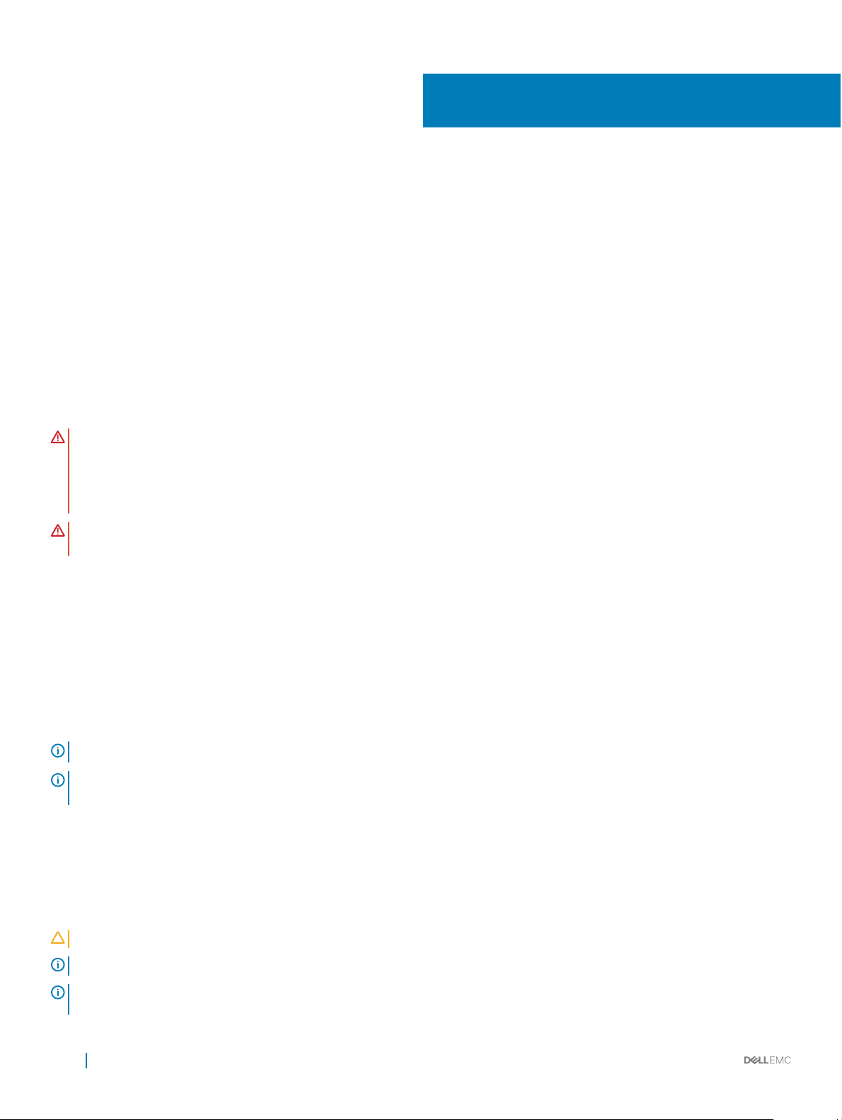
For rack spans from 22 to 23.375 inches
The switch ships without the ground lug attached. To be NEBS-compliant, attach the ground lug using these steps.
Figure 6. Switch without ground lug
1 Remove the ground lug from the shipping bag and crimp the ground wire to the lug.
The ground wire is not included.
NOTE
: The grounding cable must comply with your local electrical codes in size and color. Wires are typically green or
green with a yellow stripe.
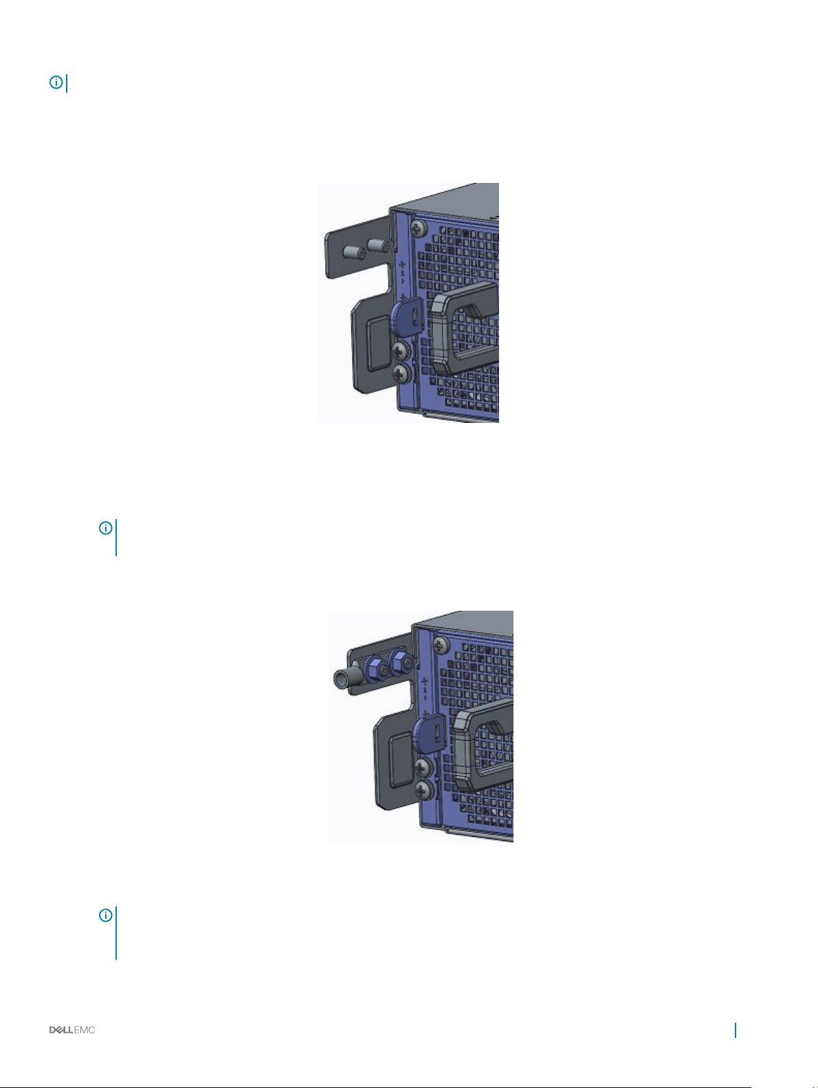
2 Attach the ground lug to the mounting bracket using two M5 nuts, included.
Torque to 30 in-lb.
Figure 7. Switch with ground lug
: For proper ventilation, position the chassis in an equipment rack or cabinet with a minimum of 5 inches (12.7 cm)
NOTE
of clearance around exhaust vents. The acceptable ambient temperature ranges are listed in the Environmental
Parameters section.
3 Attach the rack rails to the rack using four screws on the front of the rack and eight screws on the back of the rack.
NEBS compliance
17
 Loading...