

Dell S60, Force10 S60 Series System Manual

Installing the S60 System
Publication Date: December 2013

Notes, Cautions, and Warnings
NOTE: A NOTE indicates important information that helps you make better use of your computer.
CAUTION: A CAUTION indicates either potential damage to hardware or loss of data and tells you how to
avoid the problem.
WARNING: A WARNING indicates a potential for property damage, personal injury, or death.
Information in this publication is subject to change without notice.
© 2013 Dell Force10. All rights reserved.
Reproduction of these materials in any manner whatsoever without the written permission of Dell Inc. is strictly forbidden.
Trademarks used in this text: Dell™, the Dell logo, Dell Boomi™, Dell Precision™ , OptiPlex™, Latitude™, PowerEdge™, PowerVault™,
PowerConnect™, OpenManage™, EqualLogic™, Compellent™, KACE™, FlexAddress™, Force10™ and Vostro™ are trad emark s of D ell
Inc. Intel®, Pentium®, Xeon®, Core® and Celeron® are registered trademarks of Intel Corporation in the U.S. and other countries. AMD®is
a registered trademark and AMD Opteron™, AMD Phenom™ and AMD Sempron™ are trademarks of Advanced Micro Devices, Inc.
Microsoft®, Windows®, Windows Server®, Internet Explorer®, MS-DOS®, Windows Vista® and Active Directory® are either trademarks
or registered trademarks of Microsoft Corporation in the United States and/or other countries. Red Hat® and Red Hat®Enterprise Linux® are
registered trademarks of Red Hat, Inc. in the United States and/or other countries. Novell® and SUSE® are registered trademarks of Novell
Inc. in the United States and other countries. Oracle® is a registered trademark of Oracle Corporation and/or its affiliates. Citrix®, Xen®,
XenServer® and XenMotion® are either registered trademarks or trademarks of Citrix System s, Inc. in the United States and/or o ther countries.
VMware®, Virtual SMP®, vMotion®, vC enter® and vSphere® are registered trademarks or trademarks of VMware, Inc. in the United States
or other countries. IBM® is a registered trademark of International Business Machines Corporation.
Other trademarks and trade names may be used in this publication to refer to either the entities claiming the marks and names or their products.
Dell Inc. disclaims any proprietary interest in trademarks and trade names other than its own.
December 2013

1 About this Guide
Related Publications. . . . . . . . . . . . . . . . . . . . . . . . . . . . . . . . . . . . . . . . . . . . . . . . . . 5
2 The S60 System
Introduction. . . . . . . . . . . . . . . . . . . . . . . . . . . . . . . . . . . . . . . . . . . . . . . . . . . . . . . . . 6
Orderable S60 Systems. . . . . . . . . . . . . . . . . . . . . . . . . . . . . . . . . . . . . . . . . . . . 7
Features . . . . . . . . . . . . . . . . . . . . . . . . . . . . . . . . . . . . . . . . . . . . . . . . . . . . . . . . . . . 8
Ports . . . . . . . . . . . . . . . . . . . . . . . . . . . . . . . . . . . . . . . . . . . . . . . . . . . . . . . . . . . . . . 8
System Status. . . . . . . . . . . . . . . . . . . . . . . . . . . . . . . . . . . . . . . . . . . . . . . . . . . . . . . 8
LED Displays. . . . . . . . . . . . . . . . . . . . . . . . . . . . . . . . . . . . . . . . . . . . . . . . . . . . 8
3 Install the S60 System
Install the S60 System in a Rack or Cabinet. . . . . . . . . . . . . . . . . . . . . . . . . . . . . . . 11
Attach the Mounting Brackets . . . . . . . . . . . . . . . . . . . . . . . . . . . . . . . . . . . . . . 11
Install the Chassis into the Rack or Cabinet . . . . . . . . . . . . . . . . . . . . . . . . . . . 12
Attach the Ground Cable . . . . . . . . . . . . . . . . . . . . . . . . . . . . . . . . . . . . . . . . . . . . . 13
Insert Optional Modules . . . . . . . . . . . . . . . . . . . . . . . . . . . . . . . . . . . . . . . . . . . . . . 14
Install the SFP and SFP+ Optics . . . . . . . . . . . . . . . . . . . . . . . . . . . . . . . . . . . . . . . 15
Connect Stacking Ports (Optional) . . . . . . . . . . . . . . . . . . . . . . . . . . . . . . . . . . . . . . 15
Important Points to Know. . . . . . . . . . . . . . . . . . . . . . . . . . . . . . . . . . . . . . . . . . 15
Connect Two S60 Systems . . . . . . . . . . . . . . . . . . . . . . . . . . . . . . . . . . . . . . . . 17
Connect Three or More S60 Systems . . . . . . . . . . . . . . . . . . . . . . . . . . . . . . . . 18
Supply Power and Power Up the System. . . . . . . . . . . . . . . . . . . . . . . . . . . . . . . . . 19
Power Up Sequence . . . . . . . . . . . . . . . . . . . . . . . . . . . . . . . . . . . . . . . . . . . . . 19
AC Power. . . . . . . . . . . . . . . . . . . . . . . . . . . . . . . . . . . . . . . . . . . . . . . . . . . . . . 20
DC Power . . . . . . . . . . . . . . . . . . . . . . . . . . . . . . . . . . . . . . . . . . . . . . . . . . . . . 20
Hot-swap Units in a Stack. . . . . . . . . . . . . . . . . . . . . . . . . . . . . . . . . . . . . . . . . . . . . 21
4 Power Supplies
Components . . . . . . . . . . . . . . . . . . . . . . . . . . . . . . . . . . . . . . . . . . . . . . . . . . . . . . . 22
Install an AC or DC Power Supply . . . . . . . . . . . . . . . . . . . . . . . . . . . . . . . . . . . . . . 23
Replace an AC or DC Power Supply . . . . . . . . . . . . . . . . . . . . . . . . . . . . . . . . . . . . 24
5 Fans and Filters
Components . . . . . . . . . . . . . . . . . . . . . . . . . . . . . . . . . . . . . . . . . . . . . . . . . . . . . . . 26
Install a Fan Module . . . . . . . . . . . . . . . . . . . . . . . . . . . . . . . . . . . . . . . . . . . . . . . . . 26
Replace a Fan Module . . . . . . . . . . . . . . . . . . . . . . . . . . . . . . . . . . . . . . . . . . . . . . . 26
Install a Fan Filter . . . . . . . . . . . . . . . . . . . . . . . . . . . . . . . . . . . . . . . . . . . . . . . . . . . 27
6 Access the Console Ports
| 3

www.dell.com | support.dell.com
Access the RJ-45 Console Port (RS-232). . . . . . . . . . . . . . . . . . . . . . . . . . . . . . . . . 28
Access the RJ-45 Console Port with a DB-9 Adapter . . . . . . . . . . . . . . . . . . . . 29
Access the USB-B Console Port. . . . . . . . . . . . . . . . . . . . . . . . . . . . . . . . . . . . . . . . 29
7 S60 Specifications
Chassis Physical Design. . . . . . . . . . . . . . . . . . . . . . . . . . . . . . . . . . . . . . . . . . . . . . 31
Environmental Parameters . . . . . . . . . . . . . . . . . . . . . . . . . . . . . . . . . . . . . . . . 31
AC Power Requirements. . . . . . . . . . . . . . . . . . . . . . . . . . . . . . . . . . . . . . . . . . 31
DC Power Requirements. . . . . . . . . . . . . . . . . . . . . . . . . . . . . . . . . . . . . . . . . . 32
IEEE Standards. . . . . . . . . . . . . . . . . . . . . . . . . . . . . . . . . . . . . . . . . . . . . . . . . 32
Agency Compliance . . . . . . . . . . . . . . . . . . . . . . . . . . . . . . . . . . . . . . . . . . . . . . . . . 32
Network Equipment Building Systems (NEBS) Compliance . . . . . . . . . . . . . . . 32
USA Federal Communications Commission (FCC) Statem en t . . . . . . . . . . . . . 33
Canadian Department of Communication Stateme nt . . . . . . . . . . . . . . . . . . . . 33
European Union EMC Directive Conformance Statement. . . . . . . . . . . . . . . . . 34
European Community Contact. . . . . . . . . . . . . . . . . . . . . . . . . . . . . . . . . . . . . . 34
Japan: VCCI Compliance for Class A Equipment . . . . . . . . . . . . . . . . . . . . . . . 34
Korea Compliance. . . . . . . . . . . . . . . . . . . . . . . . . . . . . . . . . . . . . . . . . . . . . . . 35
China Compliance . . . . . . . . . . . . . . . . . . . . . . . . . . . . . . . . . . . . . . . . . . . . . . . 35
Safety Standards and Compliance Agency Certifications . . . . . . . . . . . . . . . . . 35
Electromagnetic Compatibility (EMC) . . . . . . . . . . . . . . . . . . . . . . . . . . . . . . . . 36
Product Recycling and Disposal . . . . . . . . . . . . . . . . . . . . . . . . . . . . . . . . . . . . 36
SD Card Removal . . . . . . . . . . . . . . . . . . . . . . . . . . . . . . . . . . . . . . . . . . . . . . . 37
Battery Replacement and Recycling . . . . . . . . . . . . . . . . . . . . . . . . . . . . . . . . . 38
4 |
8 Technical Support
The iSupport Website . . . . . . . . . . . . . . . . . . . . . . . . . . . . . . . . . . . . . . . . . . . . . . . . 41
Accessing iSupport Services. . . . . . . . . . . . . . . . . . . . . . . . . . . . . . . . . . . . . . . 41
Contacting the Technical Assistance Center . . . . . . . . . . . . . . . . . . . . . . . . . . . . . . 42
Requesting a Hardware Replacement . . . . . . . . . . . . . . . . . . . . . . . . . . . . . . . . . . . 43
1
About this Guide
This guide provides site preparation recommendations, step-by-step procedures for rack mounting and
desk mounting, inserting optional modules, and connecting to a power source.
After you have completed the hardware installation and power-up of the S60 system, for software
configuration information, refer to the FTOS Configuration Guide for the S60 System and for Command
Line Interface (CLI) information, refer to the FTOS Command Line Reference Guide for the S60 System.
NOTE: For information about upgrading your system, refer to the S60 Release Notes. For questions regarding
FTOS versions and upgrades, contact Dell Networking Technical Support.
CAUTION: To avoid electrostatic discharge (ESD) damage, wear grounding wrist straps when handling the
S60 system.
WARNING: Only trained and qualified personnel can install the S60 system. Read this guide before installing
and powering up this equipment. The S60 system contains two power cords. Disconnect both power cords
before servicing.
WARNING: This equipment contains optical transceivers, which comply with the limits of Class 1 laser
radiation.
WARNING: When no cable is connected, visible and invisible laser radiation may be emitted from the
aperture of the optical transceiver ports. Avoid exposure to laser radiation and do not stare into open
apertures.
Related Publications
For more information about the S60 system, refer to the following documents:
• FTOS Configuration Guide for the S60 System
• FTOS Command Line Reference Guide for the S60 System
•
FTOS Release Notes
NOTE: For the most recent documentation and software, visit iSupport (registration for access to some
sections is required):
for the S60 System
https://www.force10networks.com/CSPortal20/Main/SupportMain.aspx
.
About this Guide | 5
2
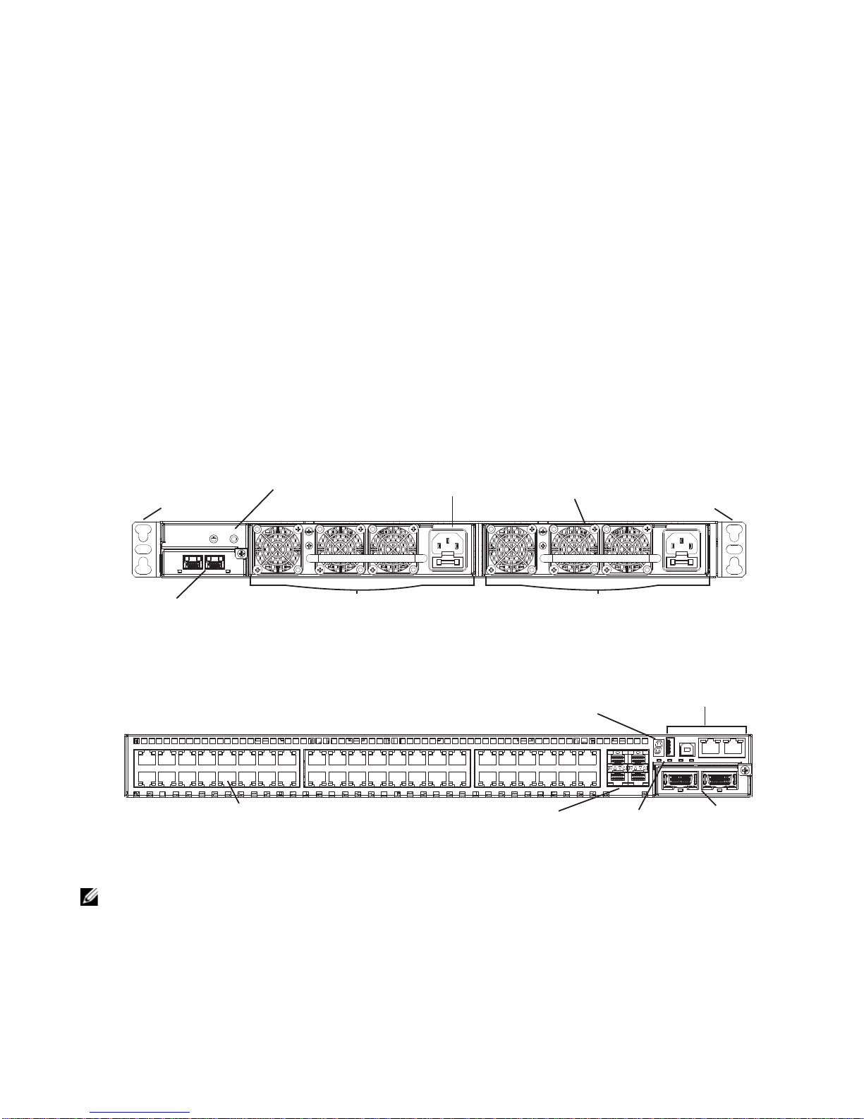
Ethernet Ports
SFP Ports
Optional
Module
(OPT0)
Management
Ports
Stack ID
Alarm
LEDs
The S60 System
Introduction
The Dell Networking S60 system is a high-performance, high-capacity, low-cost, stackable, Layer 2
switch/Layer 3 router that supports 44 built-in 10/100/1000 Base-T ports, four Small Form-Factor
Pluggable (SFP) ports, an optional Small Form-Factor Pluggable Plus (SFP+) module, and optional 12G
or 24G stacking modules.
The front of the S60 (
grounding connectors. The rear of the S60 (
ports, management ports, and displays for alarms and stacking identification.
Figure 2-1. The Front of the S60 System
Mounting Bracket Mounting Bracket
Optional Module
(OPT1)
Figure 2-2. The Rear of the S60 System
Figure 2-1
Ground Connectors
) contains the Power Supply Units (PSUs), optional module slots, and the
Power Supply (PSU0)
Figure 2-2
) contains the 44 ethernet ports, optional module
Power Connector
(AC shown)
Fans
Power Supply (PSU1)
NOTE: The ethernet ports are labeled 0-43. When cabling these ports, be sure not to interfere with the airflow
from the small vent holes above and below the ports.
The S60 System | 6

Orderable S60 Systems
You can order the S60 in several different configurations. You can order optional modules separately.
Hardware
S60: 44 port 10/100/1000 Base-T with 4 SFP ports and 2 modular slots
S60: 44 port 10/100/1000 Base-T with 4 SFP ports, 2 modular slots,1 AC PSU and 1 fan subsystem
S60: 44 port 10/100/1000 Base-T with 4 SFP ports, 2 modular slots,1 DC PSU and 1 fan subsystem
S60 Fan Subsystem with airflow from the I/O panel to the PSU
S60 Fan Subsystem with airflow from the PSU to the I/O panel
S60 AC PSU with 1 fan module
S60 AC PSU with 1 reverse-flow fan module
S60 DC PSU with 1 fan module
S60 DC PSU with 1 reverse-flow fan module
S60 2-port, 12 Gigabit stacking module
S60 1-port, 24 Gigabit stacking module
S60 2-port, 10GE SFP+ module
To successfully install the S60 system, ensure that you have the following:
• S60 chassis (or multiple chassis, if stacking)
• At least one grounded AC or DC power source per chassis
• Cable to connect the AC or DC power source to the chassis (the US AC power cable is included)
• Mounting brackets for rack installation (included)
• Screws for rack installation and #1 #2 Phillips screwdrivers (not included)
• Ground cable (not included)
• Ground cable screws (included)
• Copper/fiber cables
Other optional components are:
• Additional PSU
• Additional fan module
• Optional modules, if needed
• Stacking cables, if stacking
The S60 System | 7

Features
The S60 offers the following:
• S60 CPU and switch processor
• Up to 12 stacked systems
• Stackable switch features
• 19-inch rack-mountable
• Standard 1U chassis height
• Hot-swappable optional modules, PSUs, and fan modules
• Integrated PSU/fan module (three fans per module)
• Up to 16K MAC address entries supported with hardware-assisted aging
• Supports 9K jumbo frames
Ports
• Optional ports supporting two 2-port, 10G SFP+ modules
• 44 fixed 10/100/1000 Mbps auto-sensing and auto-MDIX RJ45 ports
• Four fixed ports supporti ng 100/1000 Base-T or 1000 Base-X using auto-media detection
• Optional ports supporting one 2-port, 24G stacking module or two 1-port, 12G stacking modules
• Console port
• Universal Serial Bus (USB)-A port
• USB-B port
System Status
You can view S60 status information in several ways, including physical displays and boot menu options.
You can also view status information through the Command Line Interface (CLI) show commands and
with Simple Network Management Protocol (SNMP) traps. For more information about these options,
refer to the FTOS Command Line Refer ence Guide for the S60 System and the FT OS Configuration Guide
for the S60 System.
LED Displays
As shown in
Stacking ID is at the top right corner on the rear of the system and is shown in hexidecimal form. A small
decimal at the bottom right of the LED indicates the stack master.
NOTE: The stacking LED display is not applicable to the first release of the S60 system.
Figure 2-3
, the S60 rear panel contains several sets of Light Emitting Diodes (LEDs). The
The S60 System | 8
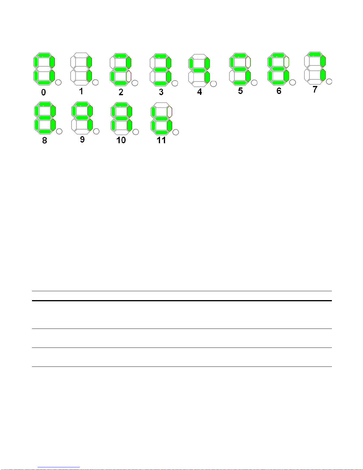
Figure 2-3. Stack ID Hexidecimal Display
• The stack master indicator displays:
• Stack Master—decimal LED ON
• Stack standby—decimal LED blinking
• Member—decimal LED Off
• Below the Stack ID LED and above the optional module ports are four LEDs that display the system
status (Table 2-1). From left to right they are:
• power
•alarm
•PSU0
•PSU1
Table 2-1. System LED Displays
Label LED Color/Display Description
Power (PWR) Green Blinking
Green
Yellow
Power Supply
(PSU0)
Power Supply
(PSU1)
Green
Yellow
Green
Yellow
System is booting up.
System power supply is OK.
System power supply is operating outside the expected parameters.
All fans are OK.
At least one fan is operating outside the expected parameters.
All fans are OK.
At least one fan is operating outside the expected parameters.
The S60 System | 9

In addition to the system LEDs, each port has status indicator LEDs.
displays.
Table 2-2. Port LED Displays
Feature Description
10/100/1000 Port LEDs • Link LED (on the left side of each port):
Green—1000M
Yellow—10/100M
Off—No link
• Activity LED (on the right side of each port):
Green—Link up on this port, full traffic
Blinking Green—Activity, transmitting or receiving packet at this port.
Off—No traffic
SFP+ Port LED • Link/Activity LED:
Green—Link up on this port, no activity taking place
Blinking Green—Activity, transmitting or receiving packet at this port.
Off—No link detected at this port
Stacking Module LEDs • Link/Activity LED:
Green—Link up on this port, no activity taking place
Blinking Green—Activity, transmitting or receiving packet in link up state
Off—No Link detected at this port
Table 2-2
lists the port LED
The S60 System | 10
3
Install the S60 System
To install the S60 system, Dell Force10 recommends completing the installation procedures in the order
presented in this chapter.
Always handle the S60 system and its components with care. Avoid dropping the system or its Field
Replaceable Units (FRUs).
This chapter describes the installation procedures as follows:
1
Install the S60 System in a Rack or Cabinet
a
Attach the Mounting Brackets
b
Install the Chassis into the Rack or Cabinet
2
Attach the Ground Cable
3
Insert Optional Modules
4
Connect Stacking Ports (Optional)
5
Supply Power and Power Up the System
WARNING: Electrostatic discharge (ESD) damage can occur if the components are mishandled. Always wear
an ESD-preventive wrist or heel ground strap when handling the S60 system and its components. As with all
electrical devices, take all the necessary safety precautions to prevent injury when installing this system.
Install the S60 System in a Rack or Cabinet
Attach the Mounting Brackets
The S60 system is shipped with mounting brackets (rack ears) and the required screws for rack or cabinet
installation. The brackets are enclosed in a package with the chassis.
NOTE: Dell Networking recommends attaching the brackets to the front of the chassis on the Power Supply
Unit (PSU) side. This provides the greatest weight support for the chassis in the rack or cabinet and is in
compliance with Bellcore Zone 4 earthquake requirements.
Install the S60 System | 11
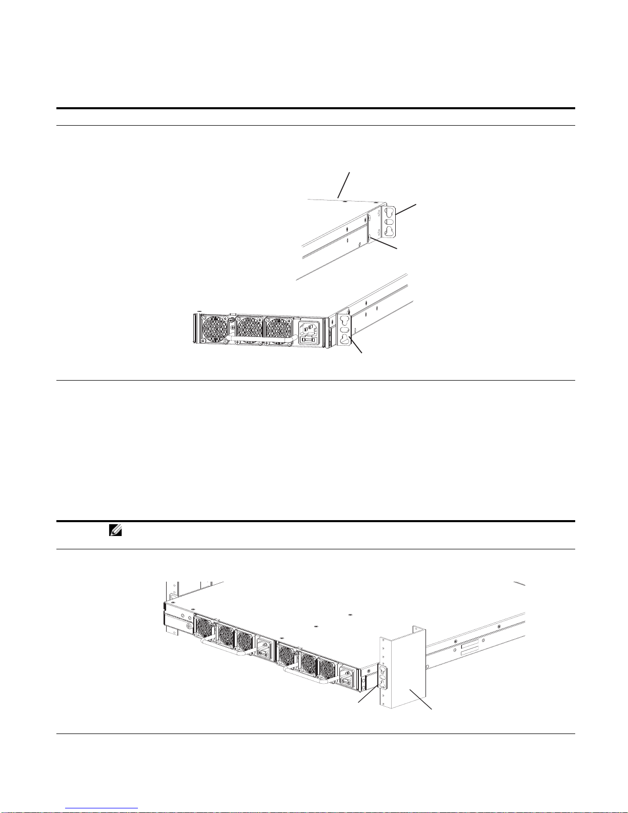
To attach the brackets to the chassis, follow these steps:
Power Supply
Power Supply
Screws
Connect to
rack/cabinet
(ear)
Connect to
rack/cabinet
(ear)
View of chassis front
View from chassis rear
Rack/Cabinet
Post
Rack Mounting
"ears"
PSU0
PSU1
Step Task
1 Take the brackets and screws out of their packaging.
2 Attach the brackets to the rear sides of the chassis using four screws for each bracket. Attach the bracket so that
the “ear” faces to the rear and the outside of the chassis.
Install the Chassis into the Rack or Cabinet
To permit access and airflow, ensure that there is adequate clearance surrounding the rack or within the
cabinet. When you install two S60 systems near each other, to permit proper airflow, position the two
chassis at least five inches (12.7 cm) apart.
T o install a switch into a two-post 19-inch equ ipment rack, using the already attached mounting brackets,
follow these steps:
Step Task
NOTE: Dell Networking recommends one person holding the S60 chassis in place while another person
attaches the brackets to the posts.
1 Attach the bracket “ears” to the rack or cabinet posts using two screws for each bracket. Ensure the screws are
tightened firmly.
Install the S60 System | 12
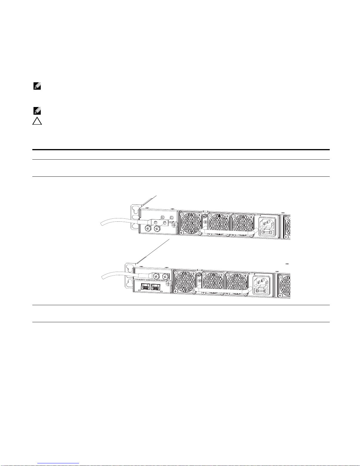
Attach the Ground Cable
1
2
The S60 system is shipped with two 10-32 screws to attach a ground cable to the system. The cable is not
included. T o properly ground the system, Dell Networking recommends using a 6AWG two-hole lug, #10
hole size, 63" spacing (not included). The two-hole lug must be a UL recognized, crimp-type lug.
NOTE: Coat the two-hole lug with an anti-oxidant compound prior to crimping. Bring any un-plated mating
surfaces to a shiny finish and coat with an anti-oxidant prior to mating. Plated mating surfaces must be clean
and free from contamination.
NOTE: The rack installation “ears” are not suitable for grounding.
CAUTION: Grounding conductors must be made of copper. Do not use aluminum conductors.
To connect the ground cable to the system, follow these steps:
Step Task
1 Take the two 10-32 screws from the package.
2 Cut the cable to the desired length. The cable length must facilitate the proper operation of the fault interrupt
circuits. Dell Networking recommends using the shortest cable route allowable.
3 Attach the two-hole lug to the system using the supplied 10-32 screws with captive internal tooth lock washers.
T orque the screws to 20 in-lbs.
4 Attach the other end of the ground cable to a suitable ground point. The rack installation “ears” are not a suitable
grounding point.
Install the S60 System | 13
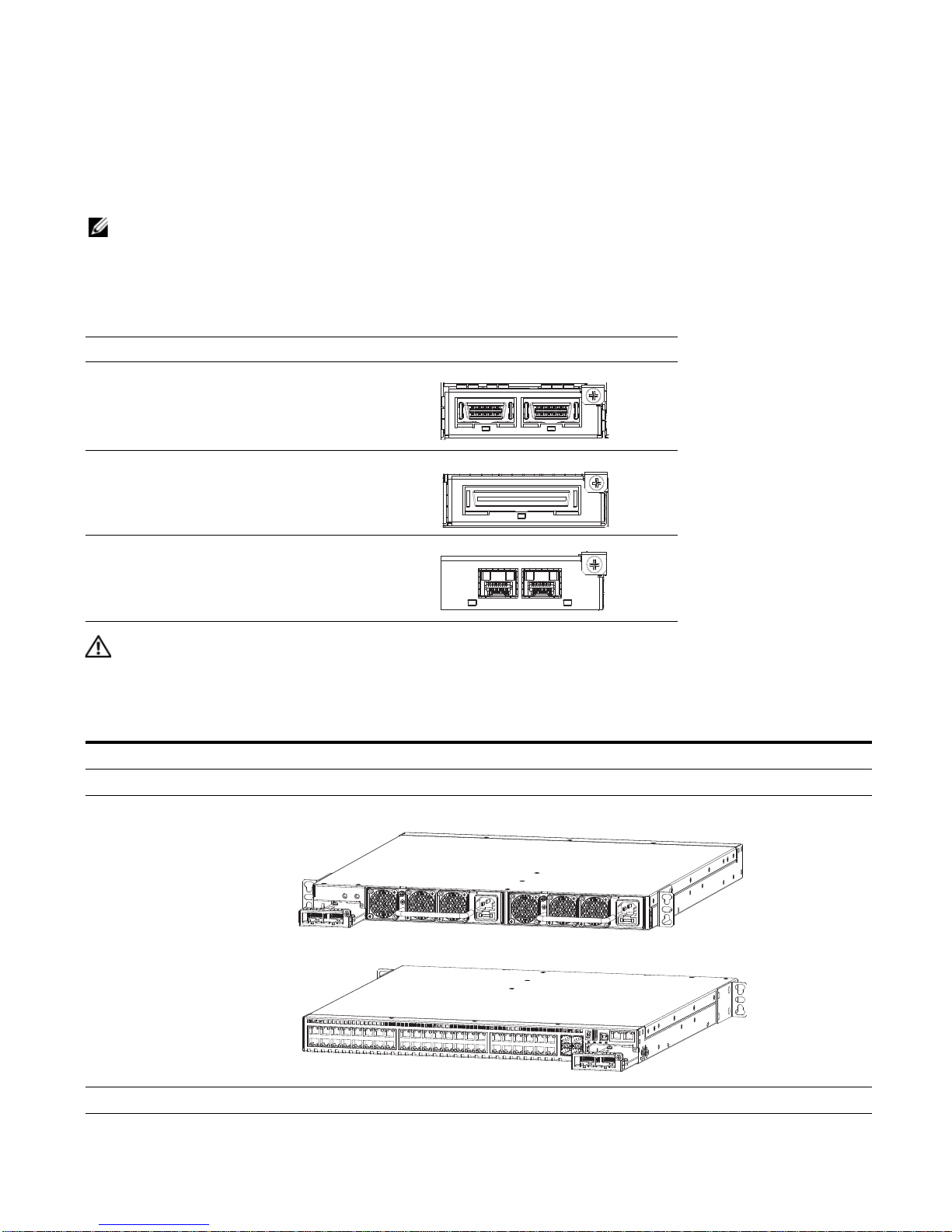
Insert Optional Modules
The S60 system has expansion slots at the front left and rear right of the system that you can use for
stacking modules or for Small Form-Factor Pluggable Plus (SFP+) devices.
modules that you can install into these expansion slots. The optional modules are hot-swappable.
NOTE: Pre-configuring the interfaces for the optical module preserves the configuration if and when you
remove an optical module. The optional 10G optical module is automatically recognized and the interfaces are
created when you insert the module into the slot. However, if the system is not already configured for the
interfaces, when you remove the optional module, the interfaces and their configurations are removed as well.
Table 3-1. Optional Modules
Module Description
2-port, 12G stacking module
1-port, 24G stacking module
2-port, 10G SFP+ optical module
Table 3-1
lists the optional
WARNING: ESD damage can occur if the components are mishandled. Always wear an ESD-preventive wrist
or heel ground strap when handling the S60 system and its components.
To install an optional module, follow these steps:
Step Task
1 Remove the faceplate covering the module slot located at the rear left or front right of the S60 system.
2 Remove the optional module from its packaging.
3 Slide the optional module into the slot.
4 Secure the captive screw on the side of the optional module.
Install the S60 System | 14
 Loading...