

Dell S5200F-ON Installation Manual

Dell EMC PowerSwitch S5200F-ON Series
Installation Guide
January 2021
Jan uar y 2 021
Rev . A 03

Notes, cautions, and warnings
NOTE: A NOTE indicates important information that helps you make better use of your product.
CAUTION: A CAUTION indicates either potential damage to hardware or loss of data and tells you how to avoid
the problem.
WARNING: A WARNING indicates a potential for property damage, personal injury, or death.
© 2018 - 2021 Dell Inc. or its subsidiaries. All rights reserved . D ell , E MC, and other trademarks are trademarks of Dell Inc. or its subsidi ari es.
Other trademarks may be trademarks of their respective owners.

Contents
Chapter 1: About this guide........................................................................................................... 5
Related documents............................................................................................................................................................. 5
Information symbols............................................................................................................................................................6
Chapter 2: S5200F-ON Series switch............................................................................................ 7
Introduction...........................................................................................................................................................................7
Features................................................................................................................................................................................ 11
Physical dimensions........................................................................................................................................................... 12
LED display.......................................................................................................................................................................... 12
LED behavior................................................................................................................................................................. 12
Prerequisites....................................................................................................................................................................... 19
S5200F-ON Series switch configurations................................................................................................................... 19
Luggage tag........................................................................................................................................................................ 20
Chapter 3: Site preparations....................................................................................................... 24
Site selection...................................................................................................................................................................... 24
Cabinet placement............................................................................................................................................................ 24
Rack mounting................................................................................................................................................................... 25
Switch ground....................................................................................................................................................................25
Fans and airflow................................................................................................................................................................ 25
Power................................................................................................................................................................................... 25
Storing components......................................................................................................................................................... 26
Chapter 4: S5200F-ON Series switch installation........................................................................ 27
S5232F-ON NEBS compliance.......................................................................................................................................27
Important information.................................................................................................................................................27
Ground cable...................................................................................................................................................................... 28
Rack or cabinet hardware installation.......................................................................................................................... 28
One-half U front-rack installation................................................................................................................................. 29
One-half U switch installation.................................................................................................................................. 30
One-half U switch removal........................................................................................................................................ 31
One U ReadyRails installation..........................................................................................................................................31
1U Tool-less mount installation.................................................................................................................................32
Two-post flush-mount installation.......................................................................................................................... 33
Two-post center-mount installation....................................................................................................................... 34
Four-post threaded installation................................................................................................................................35
Switch installation....................................................................................................................................................... 36
Two U four-post rack assembly.....................................................................................................................................38
Four-post rack mount.................................................................................................................................................38
DC power connections.....................................................................................................................................................39
S5212F-ON only DC power connections...................................................................................................................... 41
Optics installation.............................................................................................................................................................. 42
Optics removal............................................................................................................................................................. 42
Switch start up.................................................................................................................................................................. 42
Contents 3

After switch placement....................................................................................................................................................42
Switch replacement..........................................................................................................................................................43
Chapter 5: Power supplies...........................................................................................................44
Components....................................................................................................................................................................... 44
AC or DC power supply installation...............................................................................................................................46
AC or DC power supply replacement...................................................................................................................... 47
Power cable clip installation............................................................................................................................................47
Chapter 6: Fans...........................................................................................................................49
Components....................................................................................................................................................................... 49
Fan module installation.................................................................................................................................................... 50
Fan module replacement............................................................................................................................................ 51
Chapter 7: Management ports..................................................................................................... 52
RJ45 console port access............................................................................................................................................... 52
MicroUSB-B console port access................................................................................................................................. 53
USB storage mount.......................................................................................................................................................... 54
Before you install an OS.................................................................................................................................................. 54
Check your switch............................................................................................................................................................ 55
ONIE service discovery....................................................................................................................................................56
Chapter 8: Specifications............................................................................................................ 57
Chassis physical design.................................................................................................................................................... 57
IEEE standards...................................................................................................................................................................59
Agency compliance........................................................................................................................................................... 59
USA Federal Communications Commission statement............................................................................................ 59
European Union EMC directive conformance statement........................................................................................60
Japan VCCI compliance for class A equipment......................................................................................................... 60
Korean certification of compliance................................................................................................................................ 61
Safety standards and compliance agency certifications.......................................................................................... 61
Electromagnetic compatibility .......................................................................................................................................62
Product recycling and disposal...................................................................................................................................... 62
Chapter 9: Dell EMC support....................................................................................................... 64
4
Contents
About this guide
This guide provides site preparation recommendations, step-by-step procedures for rack mounting and desk mounting your
switch, inserting modules, and connecting to a power source.
CAUTION: To avoid electrostatic discharge (ESD) damage, wear grounding wrist straps when handling this
equipment.
NOTE: Only trained and qualified personnel can install this equipment. Read this guide before you install and power up this
equipment. This equipment contains two power cords. Disconnect both power cords before servicing.
NOTE: This equipment contains optical transceivers, which comply with the limits of Class 1 laser radiation.
1
Figure 1. Class 1 laser product tag
NOTE: When no cable is connected, visible and invisible laser radiation may emit from the aperture of the optical
transceiver ports. Avoid exposure to laser radiation. Do not stare into open apertures.
Regulatory
● Marketing model S5232F-ON is represented by the regulatory model E21W and the regulatory type E21W005.
● Marketing model S5248F-ON is represented by the regulatory model E21W and the regulatory type E21W002.
● Marketing model S5224F-ON is represented by the regulatory model E21W and the regulatory type E21W003.
● Marketing model S5296F-ON is represented by the regulatory model E26W and the regulatory type E26W001.
● Marketing model S5212F-ON is represented by the regulatory model E29W and the regulatory type E29W001.
Topics:
• Related documents
• Information symbols
Related documents
For more information about the S5200F-ON Series (S5232F-ON, S5248F-ON, S5296F-ON, S5224F-ON, and S5212F-ON) see
the following documents:
● Dell EMC SmartFabric User Guide
● Dell EMC SmartFabric Release Notes
● Dell EMC PowerSwitch S5200F-ON Series Set-up Guide
● Dell EMC PowerSwitch S5200F-ON Series Release Notes
● S5200-ON Series BMC User Guide
● Open Networking Hardware Diagnostic Guide
NOTE: For the most recent documentation, see Dell EMC support: www.dell.com/support.
About this guide 5

Information symbols
This book uses the following information symbols:
NOTE: The Note icon signals important operational information.
CAUTION: The Caution icon signals information about situations that could result in equipment damage or loss
of data.
NOTE: The Warning icon signals information about hardware handling that could result in injury.
NOTE: The ESD Warning icon requires that you take electrostatic precautions when handling the device.
6 About this guide

2
S5200F-ON Series switch
The following sections describe the Dell EMC S5200F-ON Series (S5232F-ON, S5248F-ON, S5296F-ON, S5224F-ON, and
S5212F-ON) switch:
Topics:
• Introduction
• Features
• Physical dimensions
• LED display
• Prerequisites
• S5200F-ON Series switch configurations
• Luggage tag
Introduction
The S5200F-ON Series (S5232F-ON, S5248F-ON, S5296F-ON, S5224F-ON, and S5212F-ON) switch is a full-featured
fixed form-factor top-of-rack (ToR) compact 10/25/40/50/100/200GbE switch for data center networks with small formfactor pluggable plus (SFP+), small form-factor pluggable 28 (SFP28), quad small form-factor pluggable 28 (QSFP28),
and quad small form-factor pluggable double density (QSFP-DD) ports. In addition, the S5200F-ON Series switch is a
10/25/40/50/100/200GbE switch with 10/25GbE links for server connections and 40/50/100GbE links for clustering—virtual
link trunking (VLT) and stacking—and uplinks to aggregation and core switches. Except for the S5212F-ON, the switch includes
two hot-swappable AC or DC power supply units (PSUs) and four hot-swappable fan units. The S5212F-ON includes two fixed
AC or DC PSUs and four fixed fan units.
● S5212F-ON—one-half rack unit
● S5224F-ON—one rack unit
● S5232F-ON—one rack unit
● S5248F-ON—one rack unit
● S5296F-ON—two rack units
The S5200F-ON Series switch includes:
● S5212F-ON: twelve 25GbE SFP28 ports and three 100GbE QSFP28 ports
● S5224F-ON: twenty-four 25GbE SFP28 ports and four 100GbE QSFP28 ports
● S5232F-ON: thirty-two 100GbE QSFP28 ports and two 10GbE SFP+ ports
● S5248F-ON: forty-eight 25GbE SFP28 ports, four 100GbE QSFP28 ports, and two 200GbE QSFP-DD ports
● S5296F-ON: ninety-six 25GbE SFP28 ports and eight 100GbE QSFP28 ports
The S5232F-ON, S5248F-ON, and S5296F-ON support the following configurations:
● 96 x 10GbE + 8 x 100GbE
● 96 x 25GbE + 8 x 100GbE
● 128 x 10GbE
● 128 x 25GbE
● 64 x 50GbE
● 32 x 40GbE
● 32 x 100GbE
The S5224F-ON supports the following configurations:
● 24 x 25GbE
● 24 x 10GbE
The S5212F-ON supports the following configurations:
● 12 x 25GbE + 3 x 100GbE
S5200F-ON Series switch 7
● 24 X 25GbE
● 12 x 10GbE + 3 x 100GbE
● 12 x 10GbE + 12 x 25 GbE
● 12 x 25GbE + 3 x 40GbE
● 24 x 10GbE
● 12 x 25GbE + 6 x 50GbE
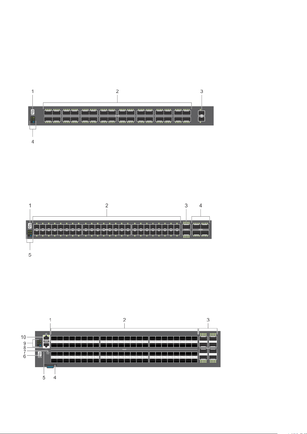
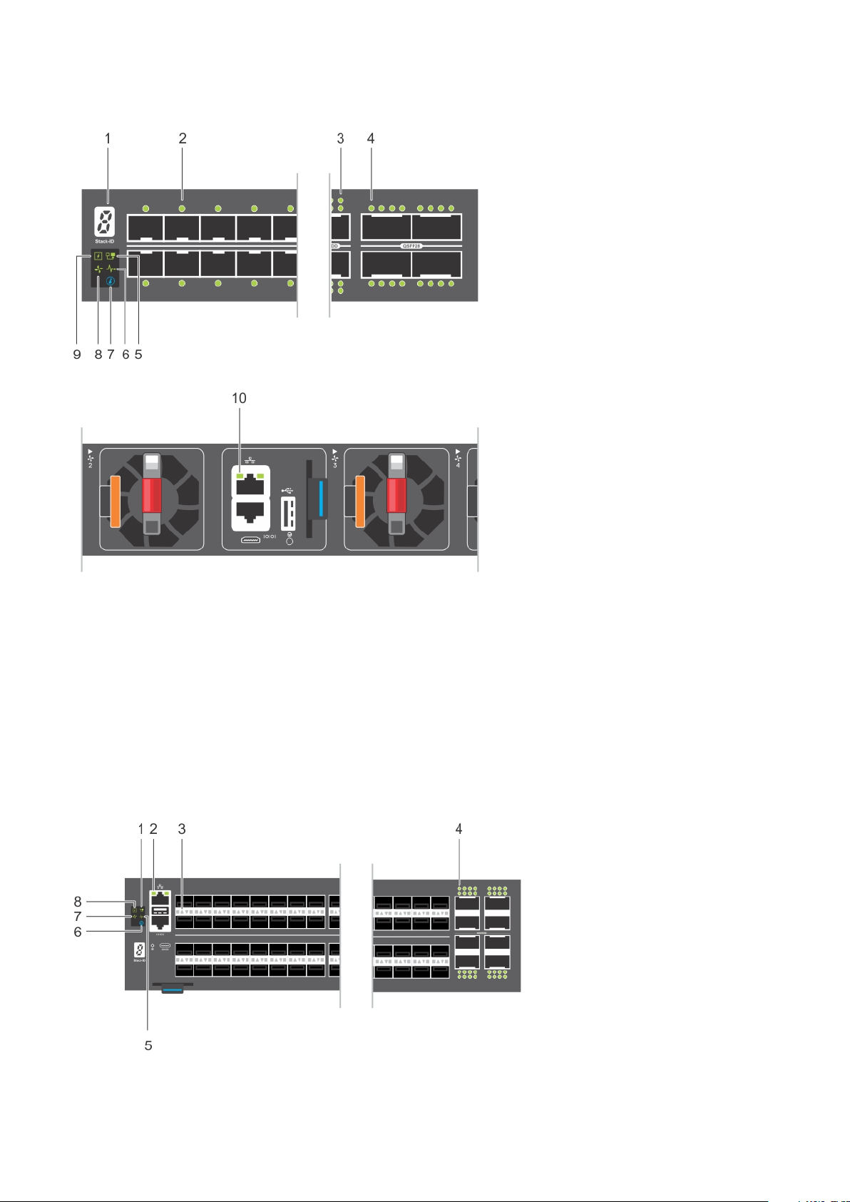
The S5232F-ON switch I/O-side view:
1. Stack ID 2. Thirty-two 100GbE QSFP28 ports
3. Two 10GbE SFP+ ports 4. LED Status Icons
The S5248F-ON switch I/O-side view:
Stack ID 2. Forty-eight 25GbE SFP28 ports
1.
3. Two 200GbE QSFP-DD ports 4. Four 100GbE QSFP28 ports
5. LED status icons
The S5296F-ON switch I/O-side view:
1.
USB Type A 2. Ninety-six 25GbE SFP28 ports
8 S5200F-ON Series switch
3. Eight 100GbE QSFP28 ports 4. Luggage tag
5. Reset button 6. Stack ID
7. MicroUSB-B console port 8. RJ45 console port
9. LED status icons 10. RJ45 Ethernet port
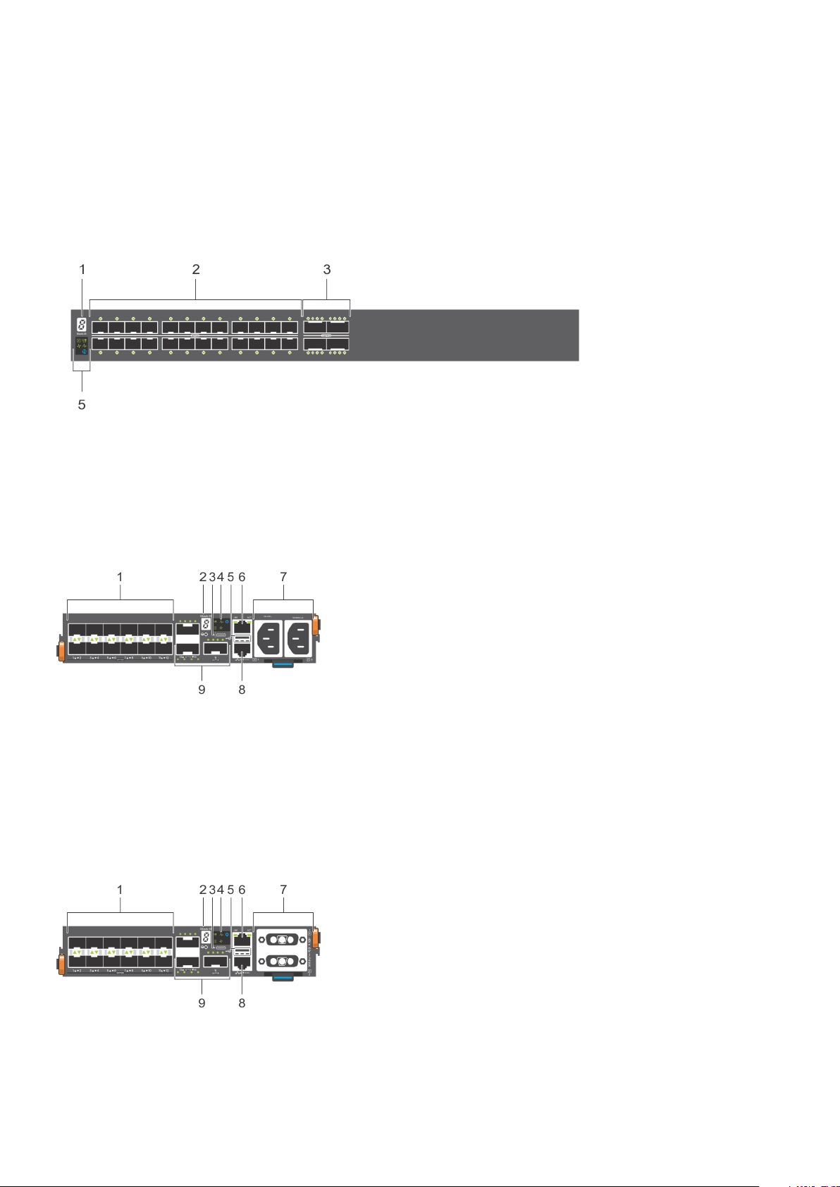
The S5224F-ON switch I/O-side view:
1. Stack ID 2. Twenty-four SFP28 ports
3. Four 100GbE QSFP28 ports 4. LED status icons
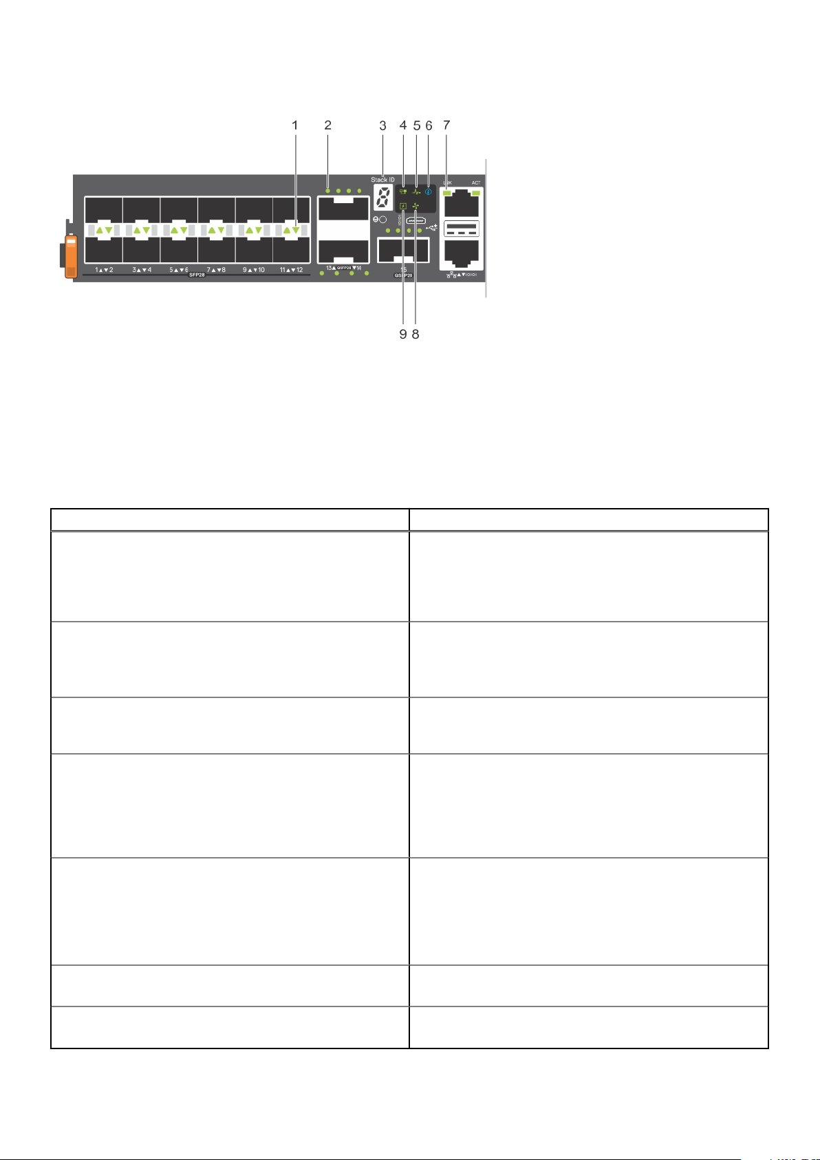
The S5212F-ON AC switch I/O-side view:
Twelve 25GbE SFP28 ports 2. Stack ID
1.
3. MicroUSB-B console port 4. LED status icons
5. USB Type A 6. RJ45 Ethernet port
7. AC PSUs 8. RJ45 console port
9. Three 100GbE QSFP28 ports
The S5212F-ON DC switch I/O-side view:
1.
Twelve 25GbE SFP28 ports 2. Stack ID
3. MicroUSB-B console port 4. LED status icons
S5200F-ON Series switch 9
5. USB Type A 6. RJ45 Ethernet port
7. DC PSUs 8. RJ45 console port
9. Three 100GbE QSFP28 ports
The S5212F-ON AC and DC switches have a reset button on the I/O-side below the Stack ID LED.
The S5200F-ON Series switch has one RJ45 serial console port, one Micro-USB type-B console port, one 10/100/1000 Base-T
Ethernet management port, one USB type-A port for the external storage, and for the S5212F-ON and S5296F-ON switches
only, one USB extension cable, which is packaged separately. Management ports are located on the PSU-side of the switch
except for the S5212F-ON switch that has the management ports on the I/O-side of the switch.
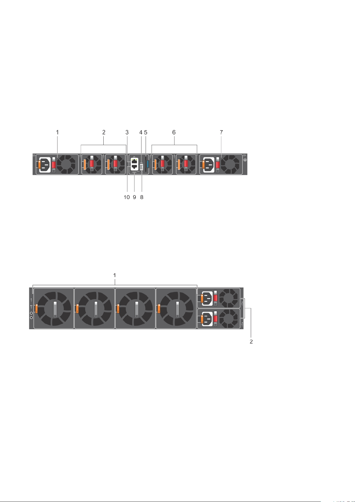
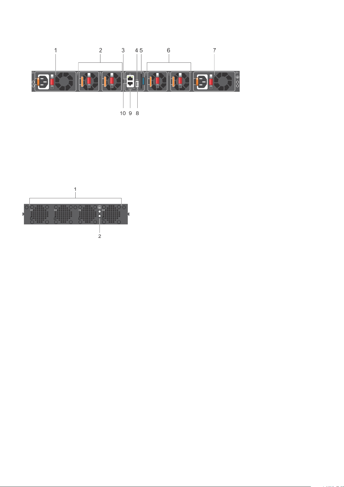
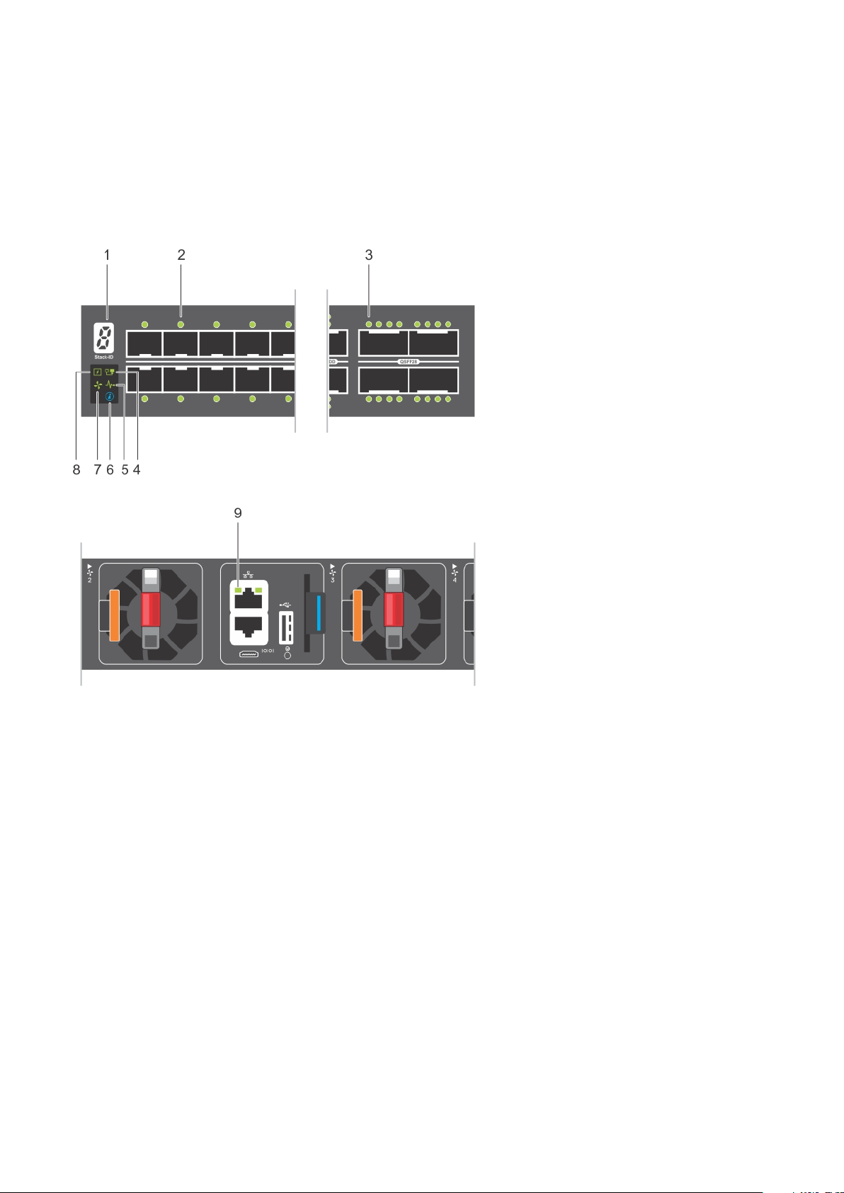
The S5232F-ON or S5248F-ON switch PSU-side view:
1. AC PSU1 2. Fan modules
3. RJ45 Ethernet port 4. USB Type A
5. Luggage tag 6. Fan modules
7. AC PSU2 8. Reset button
9. MicroUSB-B console port 10. RJ45 console port
The S5296F-ON switch PSU-side view:
1. Fan units
2. AC PSU units
The S5224F-ON switch PSU-side view:
10
S5200F-ON Series switch
1. AC PSU 2. Fans
3. RJ45 Ethernet port 4. USB Type A
5. Luggage tag 6. Fans
7. AC PSU 8. Reset button
9. MicroUSB-B console port 10. RJ45 console port
The S5212F-ON switch PSU-side view:
1. Fans
2. Holes for ground lug installation
Features
The S5200F-ON Series switch offers the following features:
● Ports:
○ S5212F-ON—twelve 25GbE SFP28 ports and three 100GbE QSFP28 ports
○ S5224F-ON—twenty-four 25GbE SFP28 ports and four 100GbE QSFP28 ports
○ S5232F-ON—thirty-two 100GbE QSFP28 ports and two 10GbE SFP+ ports
○ S5248F-ON—forty-eight 25GbE SFP28 ports, four 100GbE QSFP28 ports, and two 200GbE QSFP-DD ports
○ S5296F-ON—ninety-six 25GbE SFP28 ports and eight 100GbE QSFP28 ports
● One MicroUSB-B console port
● One RJ45 console port
● One USB Type A port for more file storage
● Four-core Intel Denverton central processing unit (CPU) system with 16 GB SDRAM and 64 GB SSD.
● One 10/100/1000BaseT Ethernet management port
● Temperature monitoring
● Software-readable thermal monitor
● Real time clock (RTC) support
● All switches except S5212F-ON: two hot-pluggable redundant PSUs
● All switches except S5212F-ON: four hot-pluggable replaceable fan modules
● S5212F-ON: two fixed PSUs
● S5212F-ON: four fixed fans modules
● Power management monitoring
● Mounting holes to accommodate two-hole ground lug
S5200F-ON Series switch
11

● S5212F-ON and S5296F-ON—USB male-female extension cable
● Switch:
○ S5212F-ON—Standard one-half rack unit
○ S5224F-ON—Standard one rack unit
○ S5232F-ON—Standard one rack unit
○ S5248F-ON—Standard one rack unit
○ S5296F-ON—Standard two rack units
Physical dimensions
The S5200F-ON Series switch have the following physical dimensions:
● S5212F-ON—one-half rack unit:
○ 7.87 x 16 x 1.72 inches (W x D x H)
○ 199.8 x 406.4 x 43.6 mm (W x D x H)
● S5224F-ON, S5232F-ON, S5248F-ON—one rack unit:
○ 17.1 x 18.1 x 1.72 inches (W x D x H)
○ 434 x 460 x 43.6 mm (W x D x H)
● S5296F-ON—two rack units:
○ 16.6 x 20.1 x 3.42 inches (W x D x H)
422 x 511 x 87 mm (W x D x H)
○
LED display
The S5200F-ON Series switch includes LED displays on the I/O side of the switch. This section describes open networking
installation environment (ONIE) LED behaviors. Some LED behaviors may change after you install your software.
LED behavior
The S5200F-ON Series switch LED behavior is seen during ONIE operations.
The S5232F-ON switch LEDs:
12
S5200F-ON Series switch
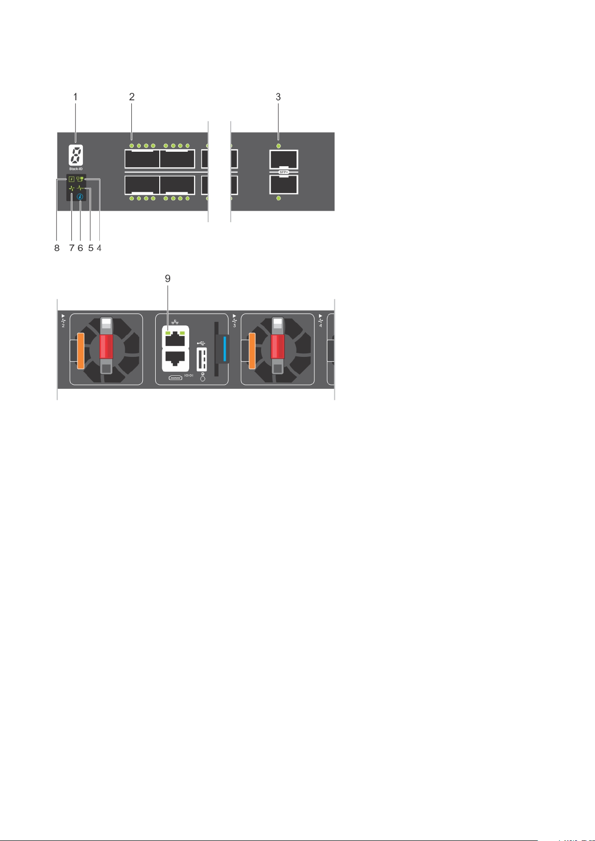
1. Stack ID LED 2. Port Activity LEDs
3. Port Activity LED 4. Master LED
5. System LED 6. Locator LED
7. Fan LED 8. Power LED
9. RJ45 Ethernet Port LED
The S5248F-ON switch LEDs:
S5200F-ON Series switch
13
1. Stack ID LED 2. Port Activity LED
3. Port Activity LEDs 4. Port Activity LEDs
5. Master LED 6. System LED
7. Locator LED 8. Fan LED
9. Power LED 10. RJ45 Ethernet Port LED
The S5296F-ON switch LEDs:
14
S5200F-ON Series switch
1. Stack ID LED 2. Port Activity LEDs
3. Port Activity LEDs 4. Port Activity LEDs
5. System LED 6. Locator LED
7. Fan LED 8. Power LED
The S5224F-ON switch LEDs:
1. Stack ID LED 2. Port Activity LED
3. Port Activity LED 4. Master LED
5. System LED 6. Locator LED
7. Fan LED 8. Power LED
9. RJ45 Port LED
The S5212F-ON switch LEDs:
S5200F-ON Series switch
15
1. Port Activity LED 2. Port Activity LED
3. Stack ID LED 4. Master LED
5. System LED 6. Locator LED
7. Link Activity LED 8. Fan LED
9. Power LED
Table 1. S5200F-ON Series switch LED behavior
LED Description
System Status/Health LED
Power LED
Master LED
FAN LED
PSU LED
● Solid green—Normal operation
● Flashing green—Booting
● Solid yellow—Critical system error
● Flashing yellow—Noncritical system error, fan failure, or
power supply failure
● Off—No power
● Solid Green—Normal operation
● Solid yellow—POST is in process
● Flashing yellow—Power supply failed
● Off—Switch is in Stacking Slave mode
● Solid green—Switch is in Stacking Master or Standalone
mode
● Off—No power
● Solid green—Normal operation; fan powered and running
at the expected RPM
● Flashing yellow—Fan fault—including incompatible airflow
direction when you insert the PSU or fan trays with
differing airflows
● Off—No power
● Solid green—Normal operation
● Flashing yellow—PSU warning event; power continues to
operate
● Flashing green—4Hz with five times on and off: Mismatch
● Flashing green—Firmware update
LOCATOR LED/System Beacon
7-Segment LED for stacking
16 S5200F-ON Series switch
● Off—Locator function disabled
● Flashing blue—Locator function enabled
● Off—No power
● Solid green—Hex digit representing the stack unit ID
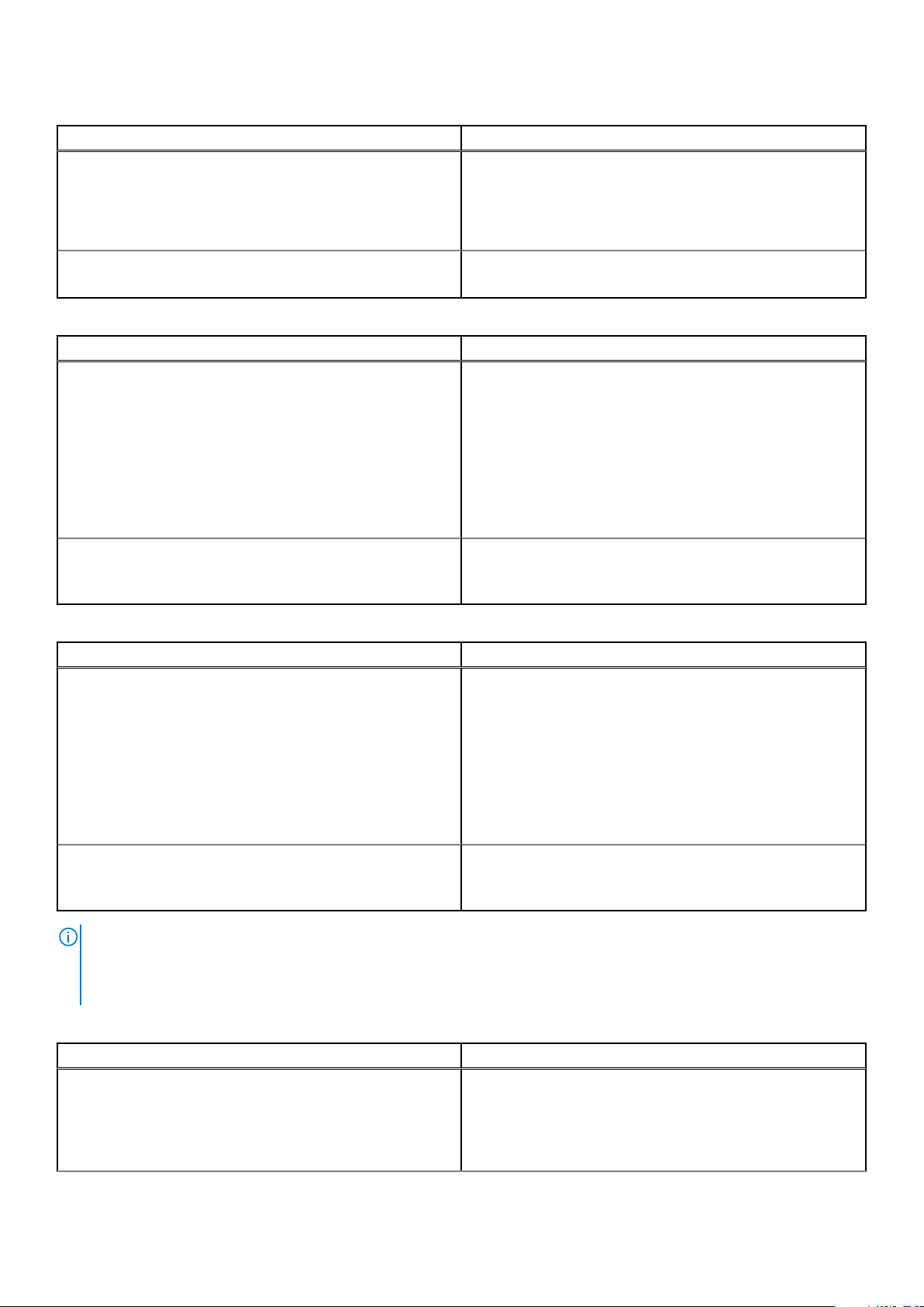
Table 2. System management Ethernet port LEDs
LED Description
Link LED
Activity LED
● Off—No link
● Solid green—Link operating at a maximum speed,
autonegotiated/forced to 1000MBase-T mode
● Solid yellow—Link operating at a lower speed,
autonegotiated/forced or 10/100MBase-T mode
● Off—No activity
● Flashing green—Port activity
Table 3. SFP28 port LEDs—S5232F-ON, S5248F-ON, and S5296F-ON
LED Description
Link LED All four LEDs:
● Off—No link
● Solid green—Link operating at maximum speed, 25G
● Solid yellow—Link operating at a lower speed, 10G or 1G
● Flashing green, ~30ms—Port activity operating at
maximum speed, 25G port
● Flashing yellow, ~30ms—Port activity operating at lower
speed, 10G or 1G port
● Flashing yellow, 1 second on/off—port beacon
Activity LED
● Off—No activity
● Flashing green—port activity at maximum speed
● Flashing yellow—port activity at lower speed
Table 4. SFP+ port LEDs—S5232F-ON
LED Description
Link LED All four LEDs:
● Off—No link
● Solid green—Link operating at maximum speed, 10G
● Solid yellow—Link operating at a lower speed, 1G
● Flashing green, ~30ms—Port activity operating at
maximum speed, 10G port
● Flashing yellow, ~30ms—Port activity operating at lower
speed, 1G port
● Flashing yellow, 1 second on/off—port beacon
Activity LED
NOTE: The first QSFP-DD port LED shows 200GbE, 100GbE, 40GbE, and 10GbE mode. All eight QSFP-DD port LEDs show
8x25GbE or 8x10GbE mode. The first and fifth QSFP-DD port LEDs show 2x100GbE mode. The first, second, fifth, and sixth
QSFP-DD port LEDs show 2x50GbE mode. The first and second LEDs for the first 2x50GbE port and the fifth and sixth
LEDs for the second 2x50GbE port.
● Off—No activity
● Flashing green—port activity at maximum speed
● Flashing yellow—port activity at lower speed
Table 5. QSFP-DD port LEDs—S5248F-ON
LED Description
Link/Activity LED—200GbE, 100GbE, 40GbE, or 10GbE mode First LED:
● Off—No link/activity
● Solid green—Port link operating at maximum speed, 200G
● Flashing green—Port activity operating at maximum
speed, 200G
S5200F-ON Series switch 17
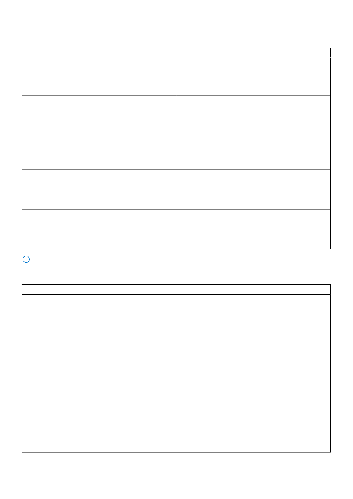
Table 5. QSFP-DD port LEDs—S5248F-ON (continued)
LED Description
● Solid yellow—Port link operating at a lower speed, 100G,
40G or 10G port
● Flashing yellow, ~30ms—Port activity operating at lower
speed, 100G, 40G or 10G port
● Flashing yellow, ~1 second on/off—Port beacon
Link/Activity LED—8x25GbE or 8x10GbE mode All eight LEDs:
● Off—No link/activity
● Solid green—Link operating at maximum speed, 8x25G
port
● Flashing green—Link activity operating at maximum speed,
8x25G port
● Solid yellow—Link operating at a lower speed, 8x10G port
● Flashing yellow, ~30ms—Port activity operating at lower
speed, 8x10G port
● Flashing yellow, 1 second on/off—Port beacon
Link/Activity LED—2x100G mode First and fifth LEDs:
● Off—No link/activity
● Solid green—Port link operating 2x100G
● Flashing yellow—Port activity at 2x100G port
● Flashing yellow, 1 second on/off—Port beacon
Link/Activity LED—4x50GbE mode First, second, fifth, and sixth LEDs"
● Off—No link/activity
● Solid green—Port link operating 2x50G
● Flashing yellow—Port activity at 2x50G port
● Flashing yellow, 1 second on/off—Port beacon
NOTE: The first QSFP28 LED shows 100GbE, 40GbE, or 10GbE mode. All four QSFP28 port LEDs show 4x25GbE or
4x10GbE mode. The first and third QSFP28 port LEDs show 2x50GbE mode.
Table 6. QSFP28 port LEDs—S5232F-ON, S5248F-ON, and S5296F-ON
LED Description
Link/Activity LED—100GbE, 40GbE, or 10GbE mode First LED:
● Off—No link/activity
● Solid green—Port link operating at maximum speed, 100G
● Flashing green—Port activity operating at maximum
speed, 100G
● Solid yellow—Port link operating at a lower speed, 40G or
10G port
● Flashing yellow, ~30ms—Port activity operating at lower
speed, 40G or 10G port
● Flashing yellow, ~1 second on/off—Port beacon
Link/Activity LED—4x25GbE or 4x10GbE mode All four LEDs:
● Off—No link/activity
● Solid green—Link operating at maximum speed, 4x25G
port
● Flashing green—Link activity operating at maximum speed,
4x25G port
● Solid yellow—Link operating at a lower speed, 4x10G port
● Flashing yellow, ~30ms—Port activity operating at lower
speed, 4x10G port
● Flashing yellow, 1 second on/off—Port beacon
Link/Activity LED—2x50G mode First and third LEDs:
18 S5200F-ON Series switch

Table 6. QSFP28 port LEDs—S5232F-ON, S5248F-ON, and S5296F-ON (continued)
LED Description
● Off—No link/activity
● Solid green—Port link operating 2x50G
● Flashing yellow—Port activity at 2x50G port
● Flashing yellow, 1 second on/off—Port beacon
Link/Activity LED—2x50GbE mode First, second, fifth, and sixth LEDs"
● Off—No link/activity
● Solid green—Port link operating 2x50G
● Flashing yellow—Port activity at 2x50G port
● Flashing yellow, 1 second on/off—Port beacon
Prerequisites
The following is a list of components that are required for successful switch installation:
NOTE: For detailed installation instructions, see Site preparations and S5200F-ON Series switch installation.
● S5200F-ON Series (S5232F-ON, S5248F-ON, S5296F-ON, S5224F-ON, and S5212F-ON) switch or multiple switches, if
stacking
● AC or DC country- and regional-specific cables to connect the AC or DC power source to each switch AC or DC power
supplies
● ReadyRail mounting brackets for rack installation, included
● Screws for rack installation, not included
● #1 and #2 Phillips screw drivers, not included
● Torx screwdriver, not included
● Ground cable screws for L-bracket, included
● Copper/fiber cables
● S5212F-ON and S5296F-ON: USB male-female extension cable
Other optional components are:
● User-supplied ground cable and separately ordered ground lug for the frame-end of the ground cable
● Extra mounting brackets
● Extra power supply unit
● Extra fan module
NOTE: The DC ground lug kit ships with the other accessories inside the shipping box.
S5200F-ON Series switch configurations
You can order the S5200F-ON Series switch in several different configurations.
● S5200F-ON Series AC or DC Normal Airflow switch:
○ S5212F-ON—one-half U, 12 x 25G SFP28 ports, 3 x 100G QSFP28 ports, two AC or DC power supplies, four fan
subsystems with airflow from the I/O side to the power supply side, and one USB male-female extension cable.
○ S5224F-ON—one U, 24 x 25G SFP28 ports, 4 x 100G QSFP28 ports, two AC or DC power supplies, and four fan
subsystems with airflow from the I/O side to the power supply side
○ S5232F-ON—one U, 32 x 100GbE ports, two AC or DC power supplies, and four fan subsystems with airflow from the
I/O side to the power supply side
○ S5248F-ON— one U, 48 x 25GbE ports, 4 x 200GbE ports, 2 x 200GbE QSFP-DD ports, two AC or DC power supplies,
and four fan subsystems with airflow from the I/O side to the power supply side
○ S5296F-ON— two U, 96 x 25GbE ports and 8 x 100GbE ports, two AC or DC power supplies, four fan subsystems with
airflow from the I/O side to the power supply side, and one USB male–female extension cable
● S5200F-ON Series AC or DC Reverse Airflow switch:
○ S5212F-ON—one-half U, 12 x 25G SFP28 ports, 3 x 100G QSFP28 ports, two AC or DC power supplies, four fan
subsystems with airflow from the power supply side to the I/O, and one USB male-female extension cable
S5200F-ON Series switch
19
○ S5224F-ON—one U, 24 x 25G SFP28 ports, 4 x 100G QSFP28 ports, two AC or DC power supplies, and four fan
subsystems with airflow from the power supply side to the I/O
○ S5232F-ON—one U, 32 x 100GbE ports, two AC or DC power supplies, and four fan subsystems with airflow from the
power supply side to the I/O
○ S5248F-ON— one U, 48 x 25GbE ports, 4 x 200GbE ports, 2 x 200GbE QSFP-DD ports, two AC or DC power supplies,
and four fan subsystems with airflow from the power supply side to the I/O
○ S5296F-ON— two U, 96 x 25GbE ports and 8 x 100GbE ports, two AC or DC power supplies, four fan subsystems with
airflow from the power supply side to the I/O, and one USB male–female extension cable
● Fan with airflow from the I/O side to the PSU side—normal airflow
● Fan with airflow from the PSU side to the I/O side—reverse airflow
● AC or DC power supply with airflow from the I/O side to the PSU side—normal airflow
● AC or DC power supply with airflow from the PSU side to the I/O side—reverse airflow
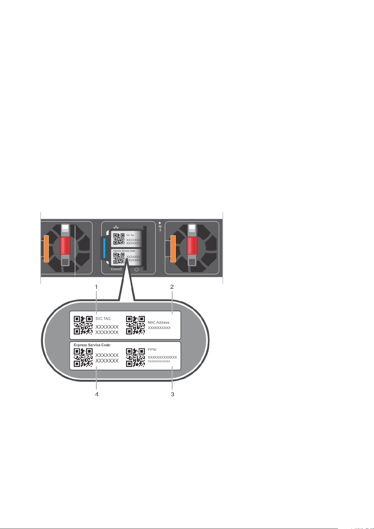
Luggage tag
The switch has a pull-out tag, known as a luggage tag, on the PSU-side of the switch. The front of the luggage tag includes
switch ID information. The back of the luggage tag includes a QRL that takes you to a How-To site where you can watch videos
about racking the switch, replacing components, configuring port channels, and so on.
The S5224F-ON, S5232F-ON, or S5248F-ON luggage tag:
1. Service tag 2. MAC address
3. PPID 4. Express service code
The S5296F-ON luggage tag:
20
S5200F-ON Series switch
 Loading...