

Dell S4810–ON, S4810 Installation Manual

Installing the S4810 System
April 2014

Notes, Cautions, and Warnings
NOTE: A NOTE indicates important information that helps you make better use of your computer.
CAUTION: A CAUTION indicates either potential damage to hardware or loss of data and tells you
how to avoid the problem.
WARNING: A WARNING indicates a potential for property damage, personal injury, or death.
Copyright © 2014 Dell Inc. All rights reserved. This product is protected by U.S. and international copyright and
intellectual property laws. Dell™ and the Dell logo are trademarks of Dell Inc. in the United States and/or other
jurisdictions. All other marks and names mentioned herein may be trademarks of their respective companies.
2014 - 04
Rev. A00

Contents
1 About this Guide........................................................................................................5
Information Symbols............................................................................................................................. 5
Related Documents...............................................................................................................................6
2 The S4810–ON System............................................................................................7
Introduction........................................................................................................................................... 7
Orderable S4810–ON Components...............................................................................................8
Prerequisite............................................................................................................................................8
Features................................................................................................................................................. 9
Ports.......................................................................................................................................................9
System Status.........................................................................................................................................9
LED Displays.....................................................................................................................................9
3 Site Preparations......................................................................................................11
Site Selection........................................................................................................................................11
Cabinet Placement...............................................................................................................................11
Rack Mounting.....................................................................................................................................12
Grounding (Optional).......................................................................................................................... 12
Fans and Airflow.................................................................................................................................. 12
Power................................................................................................................................................... 12
Storing Components........................................................................................................................... 13
4 Install the S4810–ON............................................................................................ 15
Installing the S4810–ON Chassis in a Rack or Cabinet..................................................................... 15
Attaching the Mounting Brackets into a Two-Post Rack or Cabinet.......................................... 15
Installing the System into a Two-Post Rack or Cabinet...............................................................16
Attaching the Mounting Brackets into a Four-Post Rack or Cabinet.......................................... 17
Installing the System into a Four-Post Rack or Cabinet.............................................................. 18
Attaching the Ground Cable............................................................................................................... 19
Installing the SFP+ and QSFP+ Optics...............................................................................................20
Remove the SFP+ and QSFP+ Optics...........................................................................................21
Splitting QSFP+ Ports to SFP+ Ports...................................................................................................21
Connect the Stacking Ports (Optional)...............................................................................................21
Important Points to Know............................................................................................................. 21
Connecting Two S4810–ON Systems......................................................................................... 22
Connecting Three S4810–ON Systems....................................................................................... 22
Supply Power and Power Up the System...........................................................................................22
Power Up Sequence......................................................................................................................23

AC Power.......................................................................................................................................23
DC Power...................................................................................................................................... 24
Hot-Swap Units in a Stack.................................................................................................................. 24
5 Power Supplies........................................................................................................25
Components........................................................................................................................................25
Installing an AC or DC Power Supply.................................................................................................26
Replacing an AC or DC Power Supply............................................................................................... 26
6 Fans............................................................................................................................ 27
Components........................................................................................................................................27
Installing a Fan Module....................................................................................................................... 28
Replacing a Fan Module......................................................................................................................29
7 Console Ports...........................................................................................................31
Accessing the RJ-45 Console Port (RS-232)......................................................................................31
Access the RJ-45 Console Port with a DB-9 Adapter.......................................................................32
8 Specifications.......................................................................................................... 33
Chassis Physical Design...................................................................................................................... 33
IEEE Standards...............................................................................................................................34
Agency Compliance............................................................................................................................34
USA Federal Communications Commission (FCC) Statement....................................................34
European Union EMC Directive Conformance Statement..........................................................34
Japan: VCCI Compliance for Class A Equipment........................................................................ 35
Korean Certification of Compliance.............................................................................................36
Safety Standards and Compliance Agency Certifications........................................................... 36
Electromagnetic Compatibility (EMC).......................................................................................... 37
Product Recycling and Disposal................................................................................................... 37
Removing the SD Card..................................................................................................................38
Replacing the Battery....................................................................................................................39
9 Technical Support.................................................................................................. 41
The iSupport Website.......................................................................................................................... 41
Accessing iSupport Services..........................................................................................................41
Contacting the Technical Assistance Center..................................................................................... 41
Requesting a Hardware Replacement................................................................................................42
1
About this Guide
This guide provides site preparation recommendations, step-by-step procedures for rack mounting and
desk mounting, inserting optional modules, and connecting to a power source.
.
CAUTION: To avoid electrostatic discharge (ESD) damage, wear grounding wrist straps when
handling this equipment.
WARNING: Only trained and qualified personnel can install this equipment. Read this guide
before you install and power up this equipment. This equipment contains two power cords.
Disconnect both power cords before servicing.
WARNING: This equipment contains optical transceivers, which comply with the limits of Class 1
laser radiation.
WARNING: When no cable is connected, visible and invisible laser radiation may be emitted from
the aperture of the optical transceiver ports. Avoid exposure to laser radiation and do not stare
into open apertures.
Information Symbols
This book uses the following information symbols:
NOTE: The Note icon signals important operational information.
CAUTION: The Caution icon signals information about situations that could result in equipment
damage or loss of data.
WARNING: The Warning icon signals information about hardware handling that could result in
injury.
WARNING: The ESD Warning icon requires that you take electrostatic precautions when handling
the device.
About this Guide
5

Related Documents
For more information about the S4810–ON system, refer to the Dell Networking S4810–Open
Networking (ON) Getting Started Guide.
NOTE: For the most recent documentation, visit iSupport: http://www.dell.com/support/my-
support.
6
About this Guide
2
The S4810–ON System
The following sections describe the Dell Networking S4810–ON system.
Introduction
The Dell Networking S4810–ON platform is a next-generation switch/router designed to meet the
requirements for distributed data center cores.
It is a one-rack unit (RU) chassis that supports 48 ports of 10GbE small form-factor pluggable plus (SFP+)
and four quad small form-factor pluggable plus (QSFP+) ports. For system access, the S4810–ON
includes an RS-232/RJ-45 console port and a management port for system access.
The S4810–ON input/output (I/O) side (shown in the following illustration) contains the 48 ports of
10GbE and four uplink ports of 40GbE QSFP+ autosensing ports and management ports.
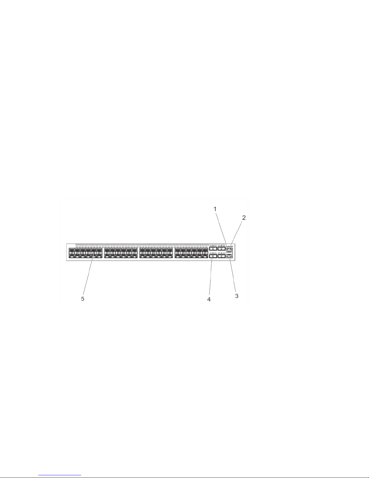
Figure 1. S4810–ON I/O-Side View
1. System LEDs
2. RS-232/RJ-45 Console Port
3. Management (Ethernet) Port
4. 40GE QSFP+ Ports
5. 10GE SFP+ Ports
The S4810–ON power supply unit (PSU) side (shown in the following illustration) contains the PSU and
fan modules.
The S4810–ON System
7
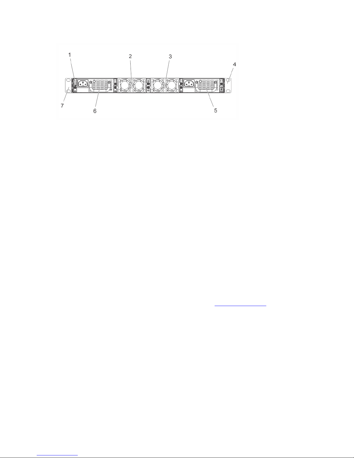
Figure 2. S4810–ON PSU-Side View
1. Mounting Bracket
2. Fan Module 1
3. Fan Module 2
4. Mounting Bracket
5. Power Supply (PSU2)
6. Power Supply (PSU1)
7. Grounding Screw
Orderable S4810–ON Components
You can order the S4810–ON system in several different configurations. You can also order optional
modules and optics separately.
You can order the following supported hardware components.
• 48-port 10G SFP+ with four QSFP+, 40G ports, one AC power supply and two fan subsystems (airflow
from I/O side to power supply side)
• 48-port 10G SFP+ with four QSFP+, 40G ports, one AC power supply and two fan subsystems (airflow
from power supply side to I/O side)
• S4810–ON Series — Fan with airflow from the I/O side to the PSU side
• S4810–ON Series — Fan with airflow from the PSU side to the I/O side
• S4810–ON Series — AC Power supply with airflow from the I/O side to the PSU side
• S4810–ON Series — AC Power supply with airflow from the PSU side to the I/O side
For a list of supported optics, refer to the S4810–ON data sheet at http://www.dell.com/ or contact your
Dell Networking representative.
Prerequisite
To successfully install the S4810–ON, ensure that you have the following components.
• S4810–ON chassis
• At least one grounded AC power source per chassis
• Cable to connect the AC power source to the chassis (US power cables included)
• Mounting brackets for rack installation (included)
• Screws for rack installation and #1 and #2 Phillips screwdrivers (not included)
8
The S4810–ON System

• Ground cable (not included, optional)
• Ground cable screws (included)
• Copper/fiber cables
Other optional components are:
• Additional power supply unit
• Additional fan module
• Additional mounting brackets (if installing in a four-post rack or cabinet)
Features
The S4810–ON offers the following features.
• S4810–ON CPU and switch processor
• Hot-swappable redundant power supply
• 19 inch rack-mountable
• Standard 1U chassis height
Ports
The Z9000 offers the following ports.
• External Serial RS-232 port (RJ45 type)
• Remote management port
• 32–port 40G QSFP+ ports
• Universal serial bus (USB)-A port
• USB-B port
• Solid state drive (SSD)
System Status
You can view S4810–ON status information using the light emitting diodes (LEDs).
LED Displays
The S4810–ON includes LED displays on the I/O side of the chassis (shown in the following illustration).
When the S4810–ON powers up or reloads, the PSU LED is solid green. For additional LED information,
refer to your third-party operating software documentation.
The S4810–ON system LEDs are:
• System status (SYS)
• Stack Master indicator (MASTER)
• Fan status (FAN)
• Power status (PSU)
Additionally, the PSUs and fans have LEDs that indicate their individual status:
The S4810–ON System
9
• PSU status
• Fan tray status
• System
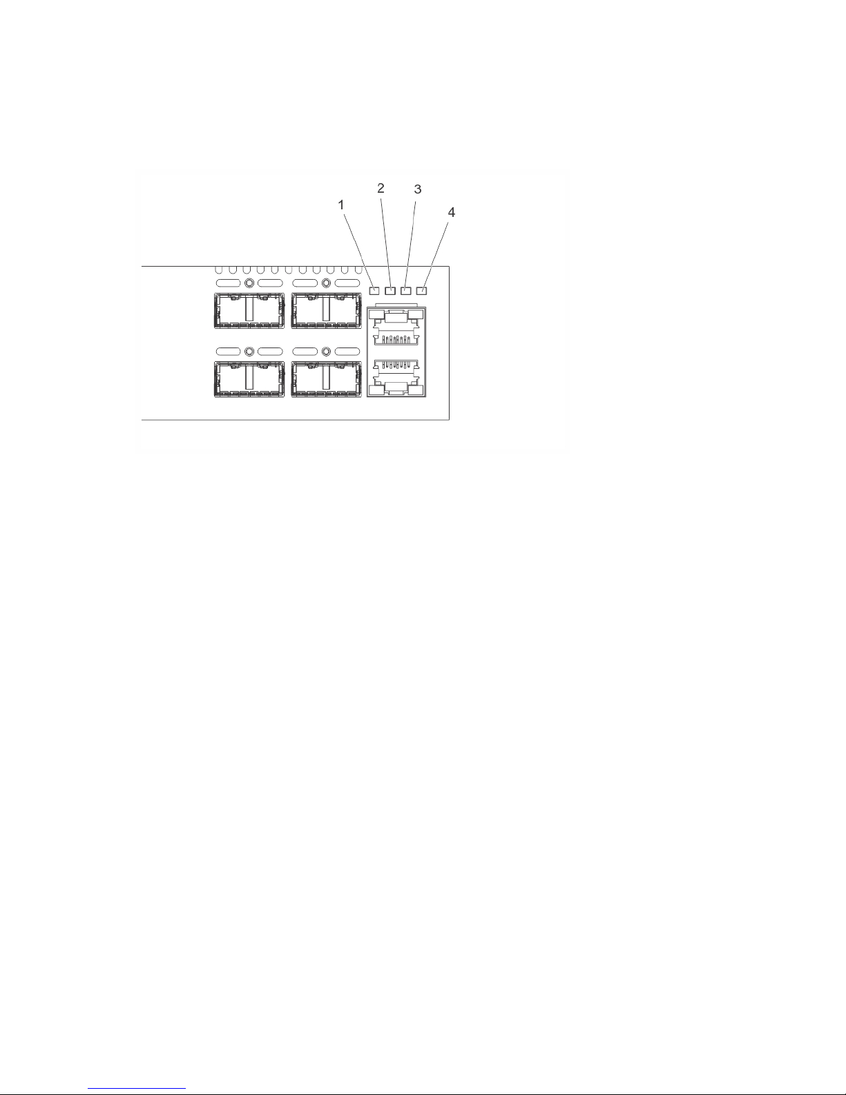
Figure 3. S4810–ON LEDs
1. SYS
2. MASTER
3. FAN
4. PSU
10
The S4810–ON System

3
Site Preparations
The S4810–ON is suitable for installation as part of a common bond network (CBN).
You can install the system in:
• network telecommunication facilities
• data centers
• other locations where the National Electric Code (NEC) applies
For more information about S4810–ON specifications, refer to Specifications.
NOTE: Install the S4810–ON system into a rack or cabinet before installing any optional
components.
Site Selection
Install Dell Networking equipment in restricted access areas.
A restricted access area is one in which service personnel can only gain access using a special tool, lock,
key or other means of security and access is controlled by the authority responsible for the location.
Ensure that the area where you install your S4810–ON system meets the following safety requirements:
• Near an adequate power source. Connect the system to the appropriate branch circuit protection as
defined by your local electrical codes.
• Environmental temperature between 32° to 104°F (from 0° to 40°C).
• Relative humidity that does not exceed 85 percent noncondensing.
• In a dry, clean, well-ventilated and temperature-controlled room, away from heat sources such as hot
air vents or direct sunlight.
• Away from sources of severe electromagnetic noise.
• Positioned in a rack or cabinet, or on a desktop with adequate space in the front, rear, and sides of the
S4810–ON for proper ventilation and access.
Cabinet Placement
Install the S4810–ON only in indoor cabinets designed for use in a controlled environment.
Do not install the S4810–ON in outside plant cabinets. For cabinet placement requirements, refer to Site
Selection.
The cabinet must be a minimum cabinet size. Airflow must be according to the Electronic Industries
Alliance (EIA) standard. Ensure that there is a minimum of 5 inches (12.7 cm) between the intake and
exhaust vents and the cabinet wall.
Site Preparations
11

Rack Mounting
When you prepare your equipment rack, ensure that the rack is earth ground.
Ground the equipment rack to the same ground point the power service in your area uses. The ground
path must be permanent.
Grounding (Optional)
Use the S4810–ON in a common bond network (CBN).
Connect the grounding cables as described in Attaching the Ground Cable.
Fans and Airflow
The S4810–ON fans support two airflow options.
Be sure to order the fans suitable to support your site’s ventilation. Use a single type of airflow fan in your
system. Do not mix reverse and normal airflows in a single S4810–ON chassis.
• Normal — airflow is from the I/O panel to the power supply. The grab-handle is labeled Exhaust.
• Reversed — airflow is from the power supply to the I/O panel. The grab-handle is labeled Intake.
For proper ventilation, position the S4810–ON in an equipment rack (or cabinet) with a minimum of 5
inches (12.7 cm) of clearance around the exhaust vents. When you install two S4810–ON systems near
each other, position the two chassis at least 5 inches (12.7 cm) apart to permit proper airflow. The
acceptable ambient temperature ranges are listed in Specifications.
The fan speed increases and decreases automatically based on the system’s state and temperature. The
switch never intentionally turns off the fans.
NOTE: Power Supplies and Fan Modules are field replaceable units. Dell Networking does not
support a mix of power supply types (such as, AC and DC) in the same switch. If a power supply is
added or replaced, it MUST match the existing type of power supply (such as, AC and AC or DC and
DC).
Power
To connect the chassis to the applicable power source, use the appropriate power cord with the S4810–
ON. An AC power cord is included with the system.
When installing AC systems, follow the requirements of the National Electrical Code, ANSI/NFPA 70
where applicable.
The system is powered-up as soon as the power cord is connected between the system and the power
source.
CAUTION: Always disconnect the power cable before you service the power supply slots.
CAUTION: Use the power supply cord as the main disconnect device on the AC system. Ensure
that the socket-outlet is located/installed near the equipment and is easily accessible.
12
Site Preparations

Storing Components
If you do not install your S4810–ON and components immediately, Dell Networking recommends
properly storing the system and all optional components until you are ready to install them.
WARNING: ESD damage can occur when components are mishandled. Always wear an ESDpreventive wrist or heel ground strap when handling the S4810–ON and its accessories. After you
remove the original packaging, place the S4810–ON and its components on an antistatic surface.
Follow these storage guidelines:
• Storage temperature must remain constant ranging from -40° to 158°F (from -40°C to 70°C).
• Store on a dry surface or floor, away from direct sunlight, heat, and air conditioning ducts.
• Store in a dust-free environment.
Site Preparations
13
 Loading...