

Dell S4248FB-ON, S4248FBL-ON Installation Manual

S4200-ON Series Installation Guide
December 2017

Notes, cautions, and warnings
NOTE: A NOTE indicates important information that helps you make better use of your computer.
CAUTION: A CAUTION indicates either potential damage to hardware or loss of data and tells you how to avoid the problem.
WARNING: A WARNING indicates a potential for property damage, personal injury, or death.
Copyright © 2017 Dell Inc. or its subsidiaries. All rights reserved. Dell, EMC, and other trademarks are trademarks of Dell Inc. or its subsidiaries. Other
trademarks may be trademarks of their respective owners.
2017 - 12
Rev. A00

Contents
1 About this guide............................................................................................................................................. 5
Regulatory...........................................................................................................................................................................5
Related documents............................................................................................................................................................5
Information Symbols..........................................................................................................................................................6
2 S4200-ON series switch................................................................................................................................7
Introduction.........................................................................................................................................................................7
Features...............................................................................................................................................................................8
Physical dimensions........................................................................................................................................................... 8
LED display..........................................................................................................................................................................8
LED behavior................................................................................................................................................................ 9
Prerequisites.......................................................................................................................................................................11
S4200-ON congurations................................................................................................................................................ 11
Luggage tag....................................................................................................................................................................... 11
3 Site preparations.......................................................................................................................................... 13
Site selection..................................................................................................................................................................... 13
Cabinet placement............................................................................................................................................................13
Rack mounting.................................................................................................................................................................. 14
Switch ground...................................................................................................................................................................14
Fans and airow................................................................................................................................................................14
Fan combinations........................................................................................................................................................14
Power.................................................................................................................................................................................14
Component storage..........................................................................................................................................................15
4 NEBS compliance.........................................................................................................................................16
Important information...................................................................................................................................................... 16
NEBS-compliant ground installation...............................................................................................................................16
5 S4200-ON Series installation....................................................................................................................... 19
Unpack the switch............................................................................................................................................................19
Unpack.........................................................................................................................................................................19
Rack or cabinet installation.............................................................................................................................................20
Rack mount safety considerations...........................................................................................................................20
ReadyRails Installation.....................................................................................................................................................20
Tool-less non-threaded mount installation...............................................................................................................21
Two-post ush-mount installation........................................................................................................................... 22
Two-post center-mount installation.........................................................................................................................23
Four-post threaded installation................................................................................................................................ 24
S4200-ON Series switch installation.............................................................................................................................25
1U front-rack installation........................................................................................................................................... 25
Ground cable.....................................................................................................................................................................27
Contents
3

Optics installation.............................................................................................................................................................28
Optics removal............................................................................................................................................................28
Switch power-up..............................................................................................................................................................28
Power up sequence...................................................................................................................................................29
After switch installation...................................................................................................................................................29
Switch replacement.........................................................................................................................................................29
6 Power supplies............................................................................................................................................ 30
Components..................................................................................................................................................................... 30
PSU LEDs.................................................................................................................................................................... 31
AC or DC power supply installation................................................................................................................................ 31
AC or DC power supply replacement...................................................................................................................... 32
Connect DC power supply to power source.................................................................................................................32
7 Fans.............................................................................................................................................................34
Components..................................................................................................................................................................... 34
Fan LEDs.....................................................................................................................................................................35
Fan module installation....................................................................................................................................................35
Fan module replacement...........................................................................................................................................35
Fan air lter replacement.......................................................................................................................................... 36
8 Management ports.......................................................................................................................................37
RS-232 console port access...........................................................................................................................................37
USB storage mount......................................................................................................................................................... 38
Before you install an OS.................................................................................................................................................. 38
Example of the Grub Bootloader............................................................................................................................. 39
Example of ONIE........................................................................................................................................................39
ONIE service discovery................................................................................................................................................... 39
9 Specications...............................................................................................................................................41
Chassis physical design....................................................................................................................................................41
IEEE standards................................................................................................................................................................. 42
Agency compliance..........................................................................................................................................................43
USA Federal Communications Commission statement...............................................................................................43
European Union EMC directive conformance statement........................................................................................... 43
Japan VCCI compliance for class A equipment............................................................................................................44
Korean certication of compliance................................................................................................................................ 44
Electromagnetic compatibility .......................................................................................................................................45
Emissions.................................................................................................................................................................... 45
Immunity..................................................................................................................................................................... 45
Safety standards and compliance agency certications.............................................................................................45
Product recycling and disposal.......................................................................................................................................46
Waste Electrical and Electronic Equipment (WEEE) directive for recovery, recycle, and reuse of IT and
telecommunications products.................................................................................................................................. 46
10 Dell EMC support....................................................................................................................................... 47
Contents
4
About this guide
This guide provides site preparation recommendations, step-by-step procedures for rack mounting and desk mounting, inserting modules,
and connecting to a power source.
CAUTION: To avoid electrostatic discharge (ESD) damage, wear grounding wrist straps when handling this equipment.
WARNING: Only trained and qualied personnel can install this equipment. Read this guide before you install and power up this
equipment. This equipment contains two power cords. Disconnect both power cords before servicing.
WARNING: This equipment contains optical transceivers, which comply with the limits of Class 1 laser radiation.
1
Figure 1. Class 1 laser product tag
WARNING: When no cable is connected, visible and invisible laser radiation may be emitted from the aperture of the optical
transceiver ports. Avoid exposure to laser radiation and do not stare into open apertures.
Regulatory
• Marketing model S4248FB-ON is represented by the regulatory model E22W and the regulatory Type E22W001.
• Marketing model S4248FBL-ON is represented by the regulatory model E22W and the regulatory Type E22W002.
Topics:
• Related documents
• Information Symbols
Related documents
For more information about the S4200-ON Series (S4248FB-ON and S4248FBL-ON), see the following documents:
• OS10 Enterprise Edition Release Notes
• OS10 Enterprise Edition User Guide
• S4200-ON Series Set-up Guide
• Open Networking Hardware Diagnostic Guide
• S4200-ON Series Release Notes
NOTE
: For the most recent documentation, visit Dell EMC support: www.dell.com/support.
About this guide 5

Information Symbols
This book uses the following information symbols:
NOTE: The Note icon signals important operational information.
CAUTION: The Caution icon signals information about situations that could result in equipment damage or loss of data.
WARNING: The Warning icon signals information about hardware handling that could result in injury.
WARNING: The ESD Warning icon requires that you take electrostatic precautions when handling the device.
6 About this guide
S4200-ON series switch
The following sections describe the Dell EMC S4200-ON Series (S4248FB-ON and S4248FBL-ON).
Topics:
• Introduction
• Features
• Physical dimensions
• LED display
• Prerequisites
• S4200-ON congurations
• Luggage tag
Introduction
The S4200-ON Series (S4248FB-ON and S4248FBL-ON) is a one rack unit (RU) compact full-featured high-density 10/25/40/100GbE
switch. The switch includes 40 small form-factor pluggable plus (SFP+) optics, six quad form-factor pluggable 28 (QSFP28) optics
(100GbE, 4x25GbE, 40GbE, and 4x10GbE), and two QSFP+ optics for 40/100GbE aggregation and 1/10GbE top-of-rack (ToR) and endof-row (EoR) applications.
The S4200-ON Series supports the following congurations:
2
• 48 x 10GbE + 6 x 100GbE
• 40 x 10GbE + 8 x 40GbE
• 48 x 10GbE + 12 x 50GbE
• 48 x 10GbE + 24 x 25GbE
• 72 x 10GbE
• 40 x 10GbE + 2 x 40GbE + 6 x 100GbE
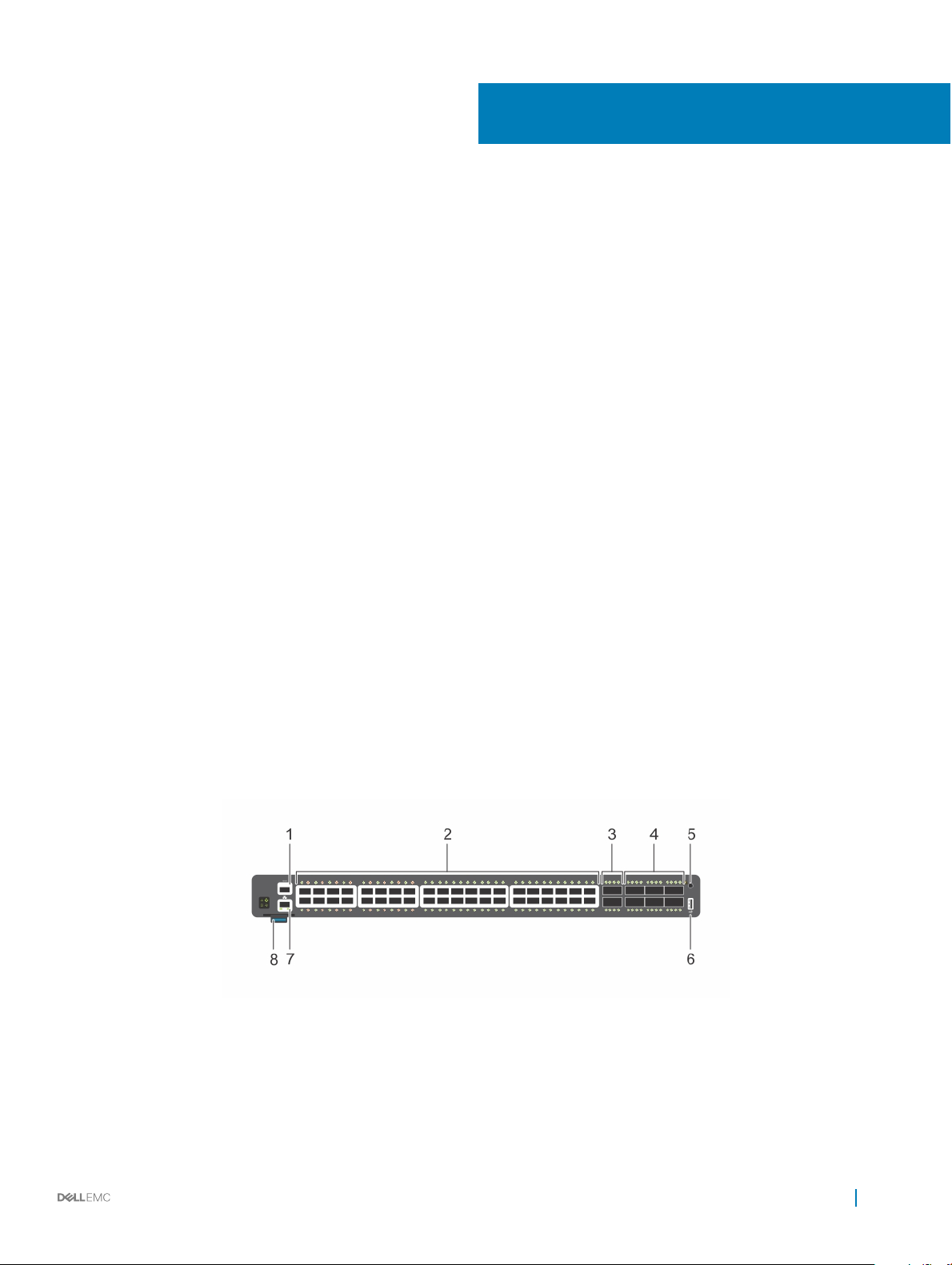
Figure 2. S4200-ON Series I/O-side view
RS-232 console port 2 40 SFP+ optical ports
1
3 Two QSFP+ optical ports 4 Six QSFP28 optical ports
5 ESD Jack 6 USB Type A
7 Ethernet management port 8 Luggage tag
S4200-ON series switch 7
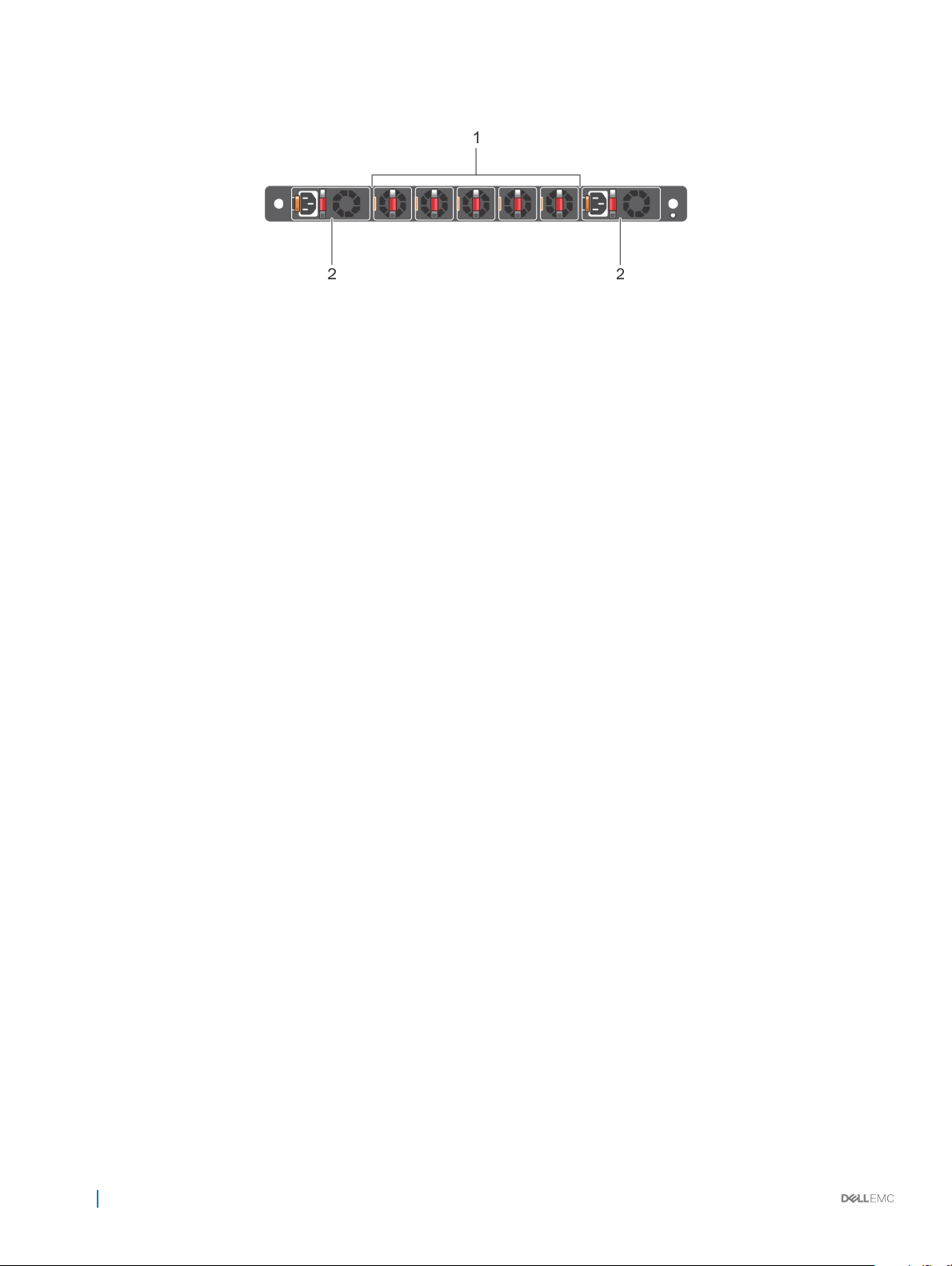
Figure 3. S4200-ON Series PSU-side view
1 Five hot-swappable fan units 2 Two hot-swappable PSUs with integrated fans
Features
The S4200-ON Series (S4248FB-ON and S4248FBL-ON) oers the following features:
• Forty 1/10GbE xed SFP+ ports
• Two QSFP+ ports supporting 40GbE or 4x10GbE breakout
• Six QSFP28 ports
• One RJ-45 console port
• One USB Type-A 2.0 port for additional le storage
• One ESD Jack
• TCAM: on-board Rangeley central processing unit (CPU) system with 32GB DDR III RAM, 64GB iSLC mSATA SSD
• Non-TCAM: on-board Rangeley CPU system with 8GB DDR III RAM, 16GB iSLC mSATA SSD
• Two hot-swappable redundant power supplies
• Five hot-swappable fans modules
• Standard 1U switch
Physical dimensions
The S4200-ON Series (S4248FB-ON and S4248FBL-ON) has the following physical dimensions:
• 434 x 462 x 44 mm (W x D x H)
• 17.1 x 18.2 x 1.72 inches (W x D x H)
• PSU and fan module Handle: 1.57 inches (40 mm)
LED display
The S4200-ON Series (S4248FB-ON and S4248FBL-ON) includes LED displays on the I/O side of the switch.
For more LED information, see your third-party operating software documentation.
S4200-ON series switch
8
LED behavior
The following S4200-ON Series (S4248FB-ON and S4248FBL-ON) switch LED behavior displays during open networking installation
environment (ONIE) operations:
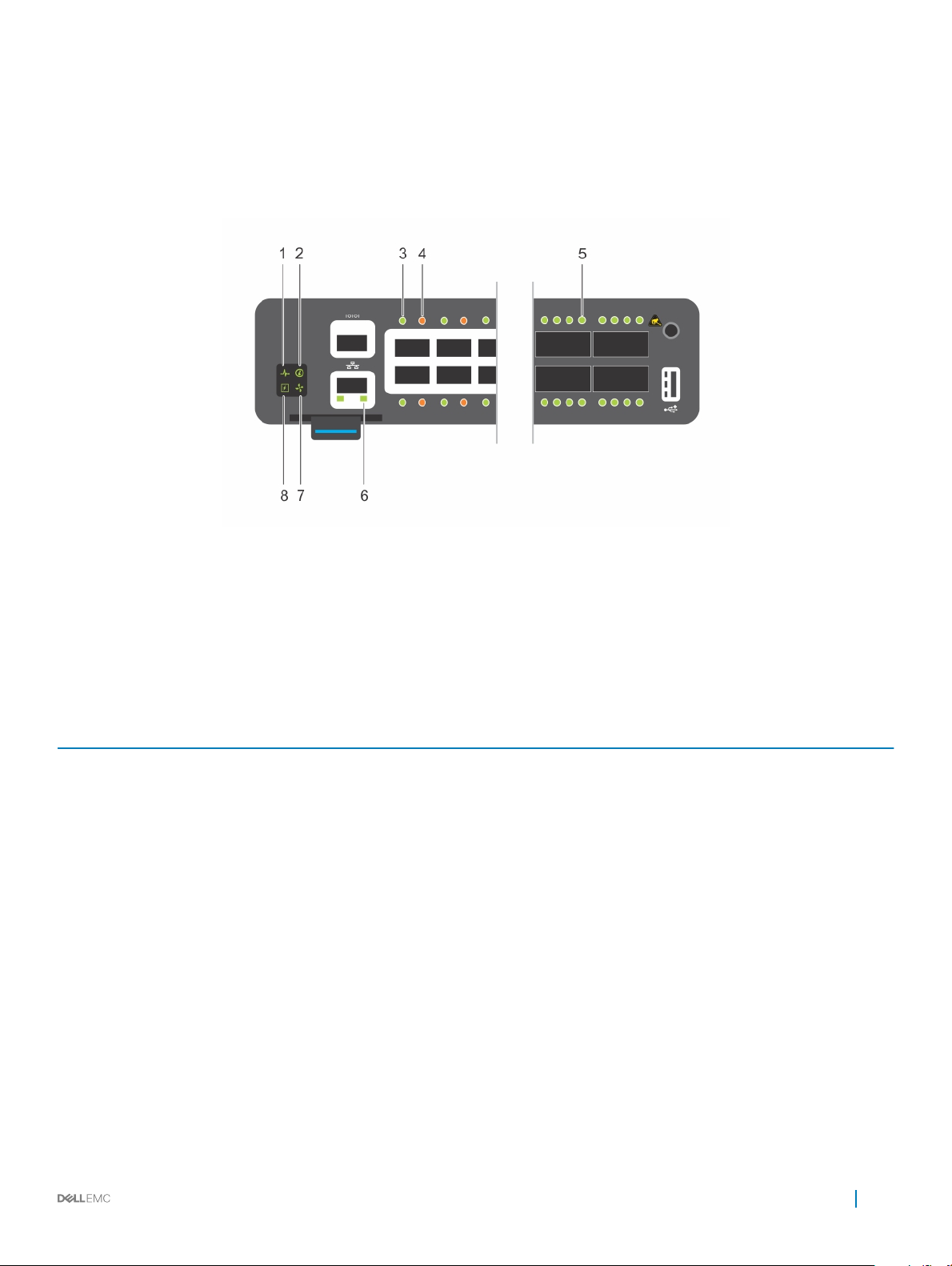
Figure 4. S4200-ON Series LEDs
1
System LED 2 Locator LED
3 Link Port LED 4 Activity Port LED
5 QSFP28 Port LED 6 RJ-45 Ethernet Port LED: Left is link; right is activity.
7 Fan LED 8 Power LED
Table 1. S4200-ON series LED behavior
LED Description
System Status/Health LED
Power LED
FAN LED
LOCATOR LED/System beacon
• Solid green—Normal Operation
• Blinking green—Booting
• Solid yellow—Critical system error
• Blinking yellow—Noncritical system error, fan failure, or power
supply failure
• O—No power
• Solid green—Normal
• Solid yellow—POST is in process
• Blinking yellow—Power supply failed
• Solid green—Fan powered and running at the expected RPM
• Blinking yellow—Fan failed, including incompatible airow
direction when you insert the PSU or fan trays with diering
airows
• O—No power
• O—Locator function is disabled
S4200-ON series switch 9

LED Description
• Blinking blue—Locator function is enabled
RJ-45 Ethernet LED
Table 2. Management Ethernet port LEDs
LED Description
Link LED
Activity LED
Table 3. SFP+ port LEDs
LED Description
• O—no link and no activity detected
• On—Activity on the port
• Solid yellow—10MHz activity
• Solid green—100MHz activity
• Blinking green—1GHz activity
• O—No Link
• Solid green—Link operating at a maximum speed,
autonegotiated/forced or 1G
• Solid yellow—Link operating at a lower speed, autonegotiated/
forced or 10/100M
• O—No Link
• Flashing green—Port activity
Link LED
Activity LED
NOTE: There are four LEDs for each QSFP+ and QSFP28 port. For each port, 100GbE or 40GbE uses only one LED, 2x50GbE
uses two LEDs, and 4x25GbE or 4x10GbE uses all four LEDs.
Table 4. QSFP+ and QSFP28 port LEDs
LED Description
Link/Activity LED
Link/Activity LED—4x25G mode or 4x10G mode
• O—No Link
• Solid green—Link operating at maximum speed, 10G
• Solid yellow — Link operating at a lower speed, 1G
• Flashing yellow, 1 second on/o—Port beacon
• O—No Link
• Flashing green—Port activity
• O—No Link
• Flashing green—Port activity operating at maximum speed,
100G for QSFP28 ports or 40G for QSFP+ ports
• Flashing yellow—Port activity operating at a lower speed
• Flashing yellow, 1 second on/o—Port beacon
• O—No Link
• Flashing green—Port activity at 4x25G on a QSFP28 port or
4x10G on a QSFP+ port
• Flashing yellow—Port activity at 4x10G on a QSFP28 port
10 S4200-ON series switch

LED Description
• Flashing yellow, 1 second on/o—Port beacon
Link/Activity LED—2x50G
• Of —No Link
• Flashing yellow—Port activity at 2x50G on a QSFP28 port
• Flashing yellow, 1 second on/o—Port beacon
Prerequisites
The following is a list of required and optional components for the S4200-ON Series (S4248FB-ON and S4248FBL-ON) switch:
NOTE: Detailed installation instructions for the S42400-ON Series are provided in Site Preparations and Install the S4200-ON
Series.
• S4200-ON Series (S4248FB-ON or S4248FBL-ON) switch or multiple switches, if stacking
• AC country- and regional-specic cables to connect the AC power source to each of the switches’ AC power supplies
• Mounting brackets for rack installation, included
• Screws for rack installation
• #1 and #2 Phillips screw drivers, not included
• Torx screwdriver, not included
• Ground cable screws, included
• Copper or ber cables
Other optional components are:
• Ground cable and lug for the frame-end of the ground cable
• Extra power supply unit
• Extra fan module
• Extra mounting brackets if installing in a four-post rack or cabinet
S4200-ON congurations
You can order the S4200-ON Series (S4248FB-ON and S4248FBL-ON) switch in several dierent congurations.
• S4248FB–ON or S4248FBL-ON AC normal airow: Forty 1/10GbE SFP+ ports, two 40GbE or 4x1/10GbE QSFP+, and six 100/40GbE
or 4x25/10GbE or 2x50GbE QSFP28 ports, two AC power supplies, and ve fan subsystems with airow from the I/O side to the
power supply side
• S4248FB–ON or S4248FBL-ON AC reverse airow: Forty 1/10GbE SFP+ ports, two 40GbE or 4x1/10GbE QSFP+, and six 100/40GbE
or 4x25/10GbE or 2x50GbE QSFP28 ports, two AC power supplies, and ve fan subsystems with airow from the power supply side to
the I/O side
• Fan with airow from the I/O side to the PSU side
• Fan with airow from the PSU side to the I/O side
• AC Power supply with airow from the I/O side to the PSU side—normal
• AC Power supply with airow from the PSU side to the I/O side—reverse
• DC Power supply with airow from the I/O side to the PSU side—normal
• DC Power supply with airow from the PSU side to the I/O side—reverse
Luggage tag
The S4200-ON Series (S4248FB-ON and S4248FBL-ON) switch has a pull-out tag, known as a luggage tag, on the I/O-side of the switch.
The front of the luggage tag includes switch ID information. The back of the luggage tag includes a QRL that takes you to a Dell EMC
How-To site where you can watch videos about racking the switch, replacing components, conguring port channels, and so on.
S4200-ON series switch
11
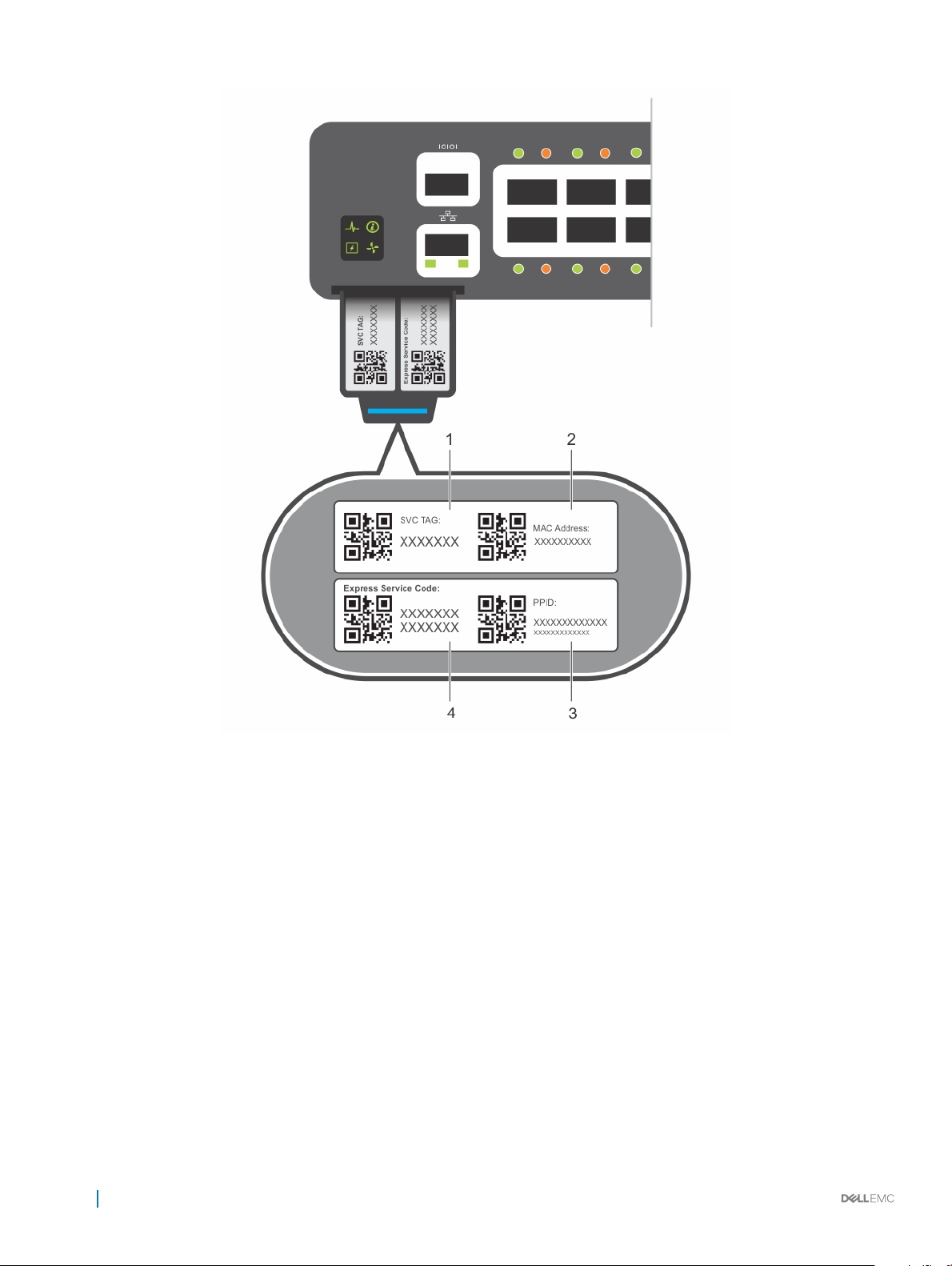
Figure 5. S4200-ON Series luggage tag
1
SVC Tag 2 MAC Address
3 PPID 4 Express Service Code
12 S4200-ON series switch

Site preparations
The S4200-ON Series (S4248FB-ON and S4248FBL-ON) switch is suitable for installation as part of a common bond network (CBN).
You can install the switch in:
• Network telecommunication facilities
• Data centers
• Other locations where the National Electric Code (NEC) applies
For more information about switch specications, see Specications.
NOTE: Install the S4200-ON Series switch in a rack or cabinet before installing any optional components.
Topics:
• Site selection
• Cabinet placement
• Rack mounting
• Switch ground
• Fans and airow
• Power
• Component storage
3
Site selection
Install Dell EMC equipment in restricted access areas.
A restricted access area is one in which service personnel can only gain access using a special tool, lock, key, or other means of security.
The authority responsible for the location controls access to the restricted area.
Ensure that the area where you install your S4200-ON Series switch meets the following safety requirements:
• Near an adequate power source. Connect the switch to the appropriate branch circuit protection according to your local electrical
codes.
• Switch environmental temperature range is from 0° to 45°C (32° to 113°F).
• Relative humidity is from 5 to 90 percent noncondensing.
• In a dry, clean, well-ventilated and temperature-controlled room, away from heat sources such as hot air vents or direct sunlight.
• Away from sources of severe electromagnetic noise.
• Inside the restricted access area, positioned in a rack or cabinet, or on a desktop with adequate space in the front, back, and sides for
proper ventilation and access.
• Install the switch in Information Technology Rooms in accordance with Article 645 of the National Electrical Code and NFPA 75.
For more information about switch storage and environmental temperatures, see Specications.
Cabinet placement
Install the S4200-ON Series (S4248FB-ON and S4248FBL-ON) switch only in indoor cabinets designed for use in a controlled environment.
Do not install the switch in outside cabinets. For cabinet placement requirements, see Site Selection.
Site preparations 13

The cabinet must meet minimum size requirements. Airow must be in accordance with the Electronic Industries Alliance (EIA) standard.
Ensure that there is a minimum of 5 inches (12.7 cm) between the intake and exhaust vents and the cabinet wall.
Rack mounting
When you prepare your equipment rack, ensure that the rack is grounded.
Ground the equipment rack to the same ground point the power service in your area uses. The ground path must be permanent.
Switch ground
Dell EMC recommends grounding your switch. Use the S4200-ON Series switch in a CBN.
Connect the grounding cables as described in S4200–ON Series Installation.
Fans and airow
The S4200-ON Series (S4248FB-ON and S4248FBL-ON) switch fans support two airow options: normal and reverse.
Fan combinations
Installation of the fans is done as part of the factory install based on stock keeping unit (SKU) type. The S4200-ON Series has SKUs that
support the following congurations:
• AC or DC PSU with fan airow from the I/O to the PSU—the red indicator is the normal airow.
• AC or DC PSU with fan airow from the PSU to the I/O—the blue indicator is the reverse airow.
Be sure to order the fans suitable to support your site’s ventilation. Use a single type of airow fan in your switch. Do not mix reverse and
normal airows in a single S4200-ON Series switch.
For proper ventilation, position the switch in an equipment rack (or cabinet) with a minimum of 5 inches (12.7 cm) of clearance around the
exhaust vents. When you install two S4200-ON Series switches near each other, to permit proper airow, position the two switches at
least 5 inches (12.7 cm) apart. The fan speed varies based on internal temperature monitoring. The S4200-ON Series never intentionally
turns o the fans.
For more information, see Fans.
Power
Use the appropriate power cord with the S4200-ON Series (S4248FB-ON and S4248FBL-ON) when connecting the switch to the power
source. An AC power cord is included with each PSU.
When installing AC or DC switches, follow the requirements of the National Electrical Code ANSI/NFPA 70, where applicable.
The switch is powered-up when the power cord is connected between the switch and the power source. For more information, see Power
Supplies.
CAUTION
Before servicing, ensure all power cords are disconnected.
: Always disconnect the power cable before you service the power supply slots. The switch has multiple power cords.
CAUTION: Use the power supply cord as the main disconnect device on the AC switch. Ensure that the socket-outlet is located/
installed near the equipment and is easily accessible.
NOTE: Module power is software controlled. You do not see module LEDs when the switch powers up in ONIE.
14 Site preparations

Component storage
If you do not install your S4200-ON Series (S4248FB-ON and S4248FBL-ON) switch and components immediately, properly store the
switch and all optional components by following these guidelines:
• Storage location temperature must remain constant. The storage range is from -40°C to 70°C (-40°F to 158°F).
• Store on a dry surface or oor, away from direct sunlight, heat, and air conditioning ducts.
• Store in a dust-free environment.
NOTE: ESD damage can occur when components are mishandled. Always wear an ESD-preventive wrist or heel ground strap
when handling the S4200-ON Series switch and its accessories. After you remove the original packaging, place the S4200-ON
Series switch and its components on an anti-static surface.
Site preparations 15
 Loading...