

Dell S4100–ON Series, S4148F-ON Series, S4128F-ON Series Installation Manual

Installation Guide for the S4100–ON Series:
S4128F-ON and S4148F-ON
July 2017

Notes, cautions, and warnings
NOTE: A NOTE indicates important information that helps you make better use of your product.
CAUTION: A CAUTION indicates either potential damage to hardware or loss of data and tells you how to avoid the problem.
WARNING: A WARNING indicates a potential for property damage, personal injury, or death.
Copyright © 2017 Dell Inc. or its subsidiaries. All rights reserved. Dell, EMC, and other trademarks are trademarks of Dell Inc. or its subsidiaries. Other
trademarks may be trademarks of their respective owners.
2017 - 07
Rev. A00

Contents
1 About this guide............................................................................................................................................. 5
Related documents............................................................................................................................................................5
Information symbols...........................................................................................................................................................5
2 S4100–ON Series switch............................................................................................................................... 7
Introduction.........................................................................................................................................................................7
Features...............................................................................................................................................................................9
Physical dimensions........................................................................................................................................................... 9
System status.....................................................................................................................................................................9
LED display..........................................................................................................................................................................9
LED behavior...............................................................................................................................................................10
Prerequisites...................................................................................................................................................................... 13
S4100–ON Series congurations....................................................................................................................................14
Luggage tag.......................................................................................................................................................................15
3 Site preparations.......................................................................................................................................... 16
Site selection.....................................................................................................................................................................16
Cabinet placement............................................................................................................................................................16
Rack mounting.................................................................................................................................................................. 17
Switch ground...................................................................................................................................................................17
Fans and airow................................................................................................................................................................17
Fan combinations........................................................................................................................................................17
Power................................................................................................................................................................................. 17
Storing components.........................................................................................................................................................18
4 S4100–ON Series installation....................................................................................................................... 19
Unpack the switch............................................................................................................................................................19
Unpack.........................................................................................................................................................................19
Rack or cabinet installation.............................................................................................................................................20
Rack mount safety considerations...........................................................................................................................20
ReadyRails installation..................................................................................................................................................... 20
1U Tool-less mount installation..................................................................................................................................21
Two-post ush-mount installation........................................................................................................................... 22
Two-post center-mount installation.........................................................................................................................23
Four-post threaded installation................................................................................................................................ 24
S4100-ON Series installation..........................................................................................................................................25
1U front-rack installation........................................................................................................................................... 25
Optics installation............................................................................................................................................................. 27
Optics removal............................................................................................................................................................28
Switch power-up..............................................................................................................................................................28
Power up sequence................................................................................................................................................... 28
After switch installation...................................................................................................................................................28
Contents
3

5 Power supplies............................................................................................................................................ 29
Components..................................................................................................................................................................... 29
PSU LEDs................................................................................................................................................................... 30
AC or DC power supply installation............................................................................................................................... 30
AC or DC power supply replacement....................................................................................................................... 31
DC power supply connection.......................................................................................................................................... 31
6 Fans.............................................................................................................................................................33
Components..................................................................................................................................................................... 33
Fan LEDs.....................................................................................................................................................................34
Fan module installation....................................................................................................................................................34
Fan module replacement...........................................................................................................................................34
7 Management ports.......................................................................................................................................35
RS-232 console port access...........................................................................................................................................35
USB storage..................................................................................................................................................................... 36
USB-B console port access............................................................................................................................................36
Before you install an OS.................................................................................................................................................. 37
Grub bootloader example..........................................................................................................................................37
ONIE example............................................................................................................................................................. 37
ONIE service discovery................................................................................................................................................... 38
8 Specications..............................................................................................................................................40
Chassis physical design...................................................................................................................................................40
IEEE standards................................................................................................................................................................. 42
Agency compliance..........................................................................................................................................................42
USA Federal Communications Commission (FCC) statement...................................................................................42
European Union EMC directive conformance statement........................................................................................... 42
Japan: VCCI compliance for class A equipment...........................................................................................................43
Korean certication of compliance................................................................................................................................ 44
Safety standards and compliance agency certications.............................................................................................44
Electromagnetic compatibility (EMC)........................................................................................................................... 44
Emissions.....................................................................................................................................................................44
Immunity..................................................................................................................................................................... 45
Product recycling and disposal.......................................................................................................................................45
Waste Electrical and Electronic Equipment (WEEE) directive for recovery, recycle, and reuse of IT and
telecommunications products.................................................................................................................................. 45
9 Dell EMC support.........................................................................................................................................47
Contents
4
About this guide
This guide provides site preparation recommendations, step-by-step procedures for rack mounting and desk mounting, inserting modules,
and connecting to a power source.
CAUTION: To avoid electrostatic discharge (ESD) damage, wear grounding wrist straps when handling this equipment.
WARNING: Only trained and qualied personnel can install this equipment. Read this guide before you install and power up this
equipment. This equipment contains two power cords. Disconnect both power cords before servicing.
WARNING: This equipment contains optical transceivers, which comply with the limits of Class 1 laser radiation.
1
Figure 1. Class 1 laser product tag
WARNING: When no cable is connected, visible and invisible laser radiation may be emitted from the aperture of the optical
transceiver ports. Avoid exposure to laser radiation. Do not stare into open apertures.
Topics:
• Related documents
• Information symbols
Related documents
For more information about the S4100–ON Series, see the following documents:
• OS10 Enterprise Edition Release Notes
• OS10 Enterprise Edition User Guide
• Dell S4100–ON Series Setup Guide
• Dell Open Networking Hardware Diagnostic Guide
• Dell EMC S4100–ON Series Release Notes
NOTE
: For the most recent documentation, visit Dell EMC support: www.dell.com/support.
Information symbols
This book uses the following information symbols:
NOTE
: The Note icon signals important operational information.
CAUTION: The Caution icon signals information about situations that could result in equipment damage or loss of data.
About this guide 5

WARNING: The Warning icon signals information about hardware handling that could result in injury.
WARNING: The ESD Warning icon requires that you take electrostatic precautions when handling the device.
6 About this guide

S4100–ON Series switch
The following sections describe the Dell EMC S4100–ON Series (S4128F-ON and S4148F-ON) switch:
Topics:
• Introduction
• Features
• Physical dimensions
• System status
• LED display
• Prerequisites
• S4100–ON Series congurations
• Luggage tag
Introduction
The S4100–ON Series (S4128F-ON and S4148F-ON) is a one rack unit (RU), full-featured xed form-factor top-of-rack (ToR)
10/25/40/50/100GbE switch for 10G servers with small form-factor pluggable plus (SFP+), quad small form-factor pluggable plus (QSFP
+), and quad small form-factor pluggable (QSFP28) ports.
: For specic port prole details, see the
NOTE
Guide
.
OS10 Enterprise Edition User
2
The S4100F-ON Series supports the following congurations:
Table 1. S4100-ON Series supported
S4128F-ON S4148F-ON
28 x 10G + 2 x 100G 48 x 10G + 4 x 100G
28 x 10G + 2 x 40G 48 x 10G + 6 x 40G
28 x 10G + 4 x 50G 48 x 10G + 8 x 50G
28 x 10G + 8 x 25G 48 x 10G + 16 x 25G
36 x 10G 72 x 10G
The following table lists the S4100–ON Series I/O-side details:
Table 2. S4100–ON Series I/O-side details
Platform Description
S4128F-ON
• 28 xed 10GbE SFP+ ports
• 2 xed 100GbE QSFP28 ports
• seven-segment stacking indicator
• 1 micro-USB-B console port
congurations
S4100–ON Series switch 7
Platform Description
• 1 USB type-A port
S4148F-ON
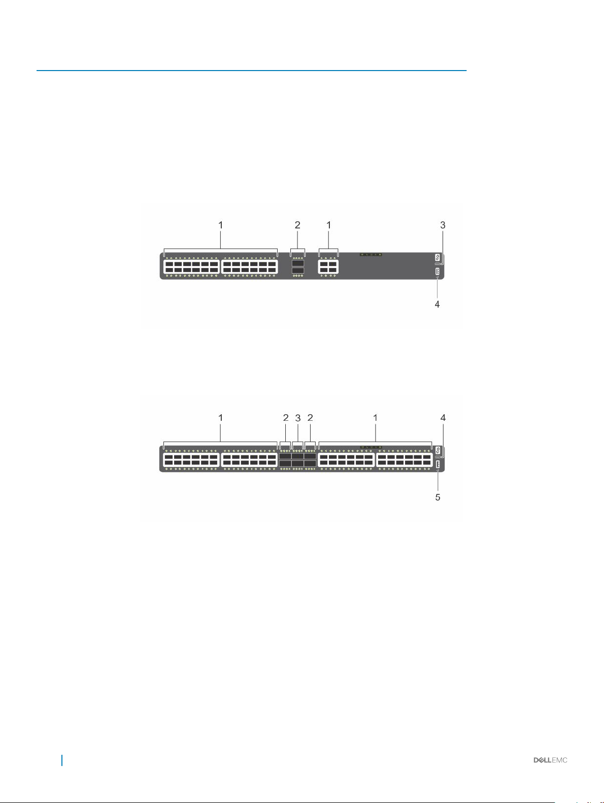
Figure 2. S4128F-ON I/O-side view
1
Twenty-eight SFP+ optical ports 2 Two QSFP28 optical ports
3 Micro USB-B console port 4 USB Type-A
• 48 xed 10GbE SFP+ ports
• 2 xed 40GbE QSFP+ ports
• 4 xed 100GbE QSFP28 ports
• seven-segment stacking indicator
• 1 micro-USB-B console port
• 1 USB type-A port
Figure 3. S4148F-ON I/O-side view
1
Forty-eight SFP+ optical ports 2 Four QSFP28
3 Two QSFP+ optical ports 4 Micro USB-B console port
5 USB Type-A
The S4100–ON Series PSU-side of the switch has two hot-swappable power supplies (PSUs) with integrated fans and four hot-swappable
fan trays. The platforms include one RJ-45 10/100/1000 Base-T Ethernet management port and one RJ-45 console port on the PSU side
of the switch.
S4100–ON Series switch
8
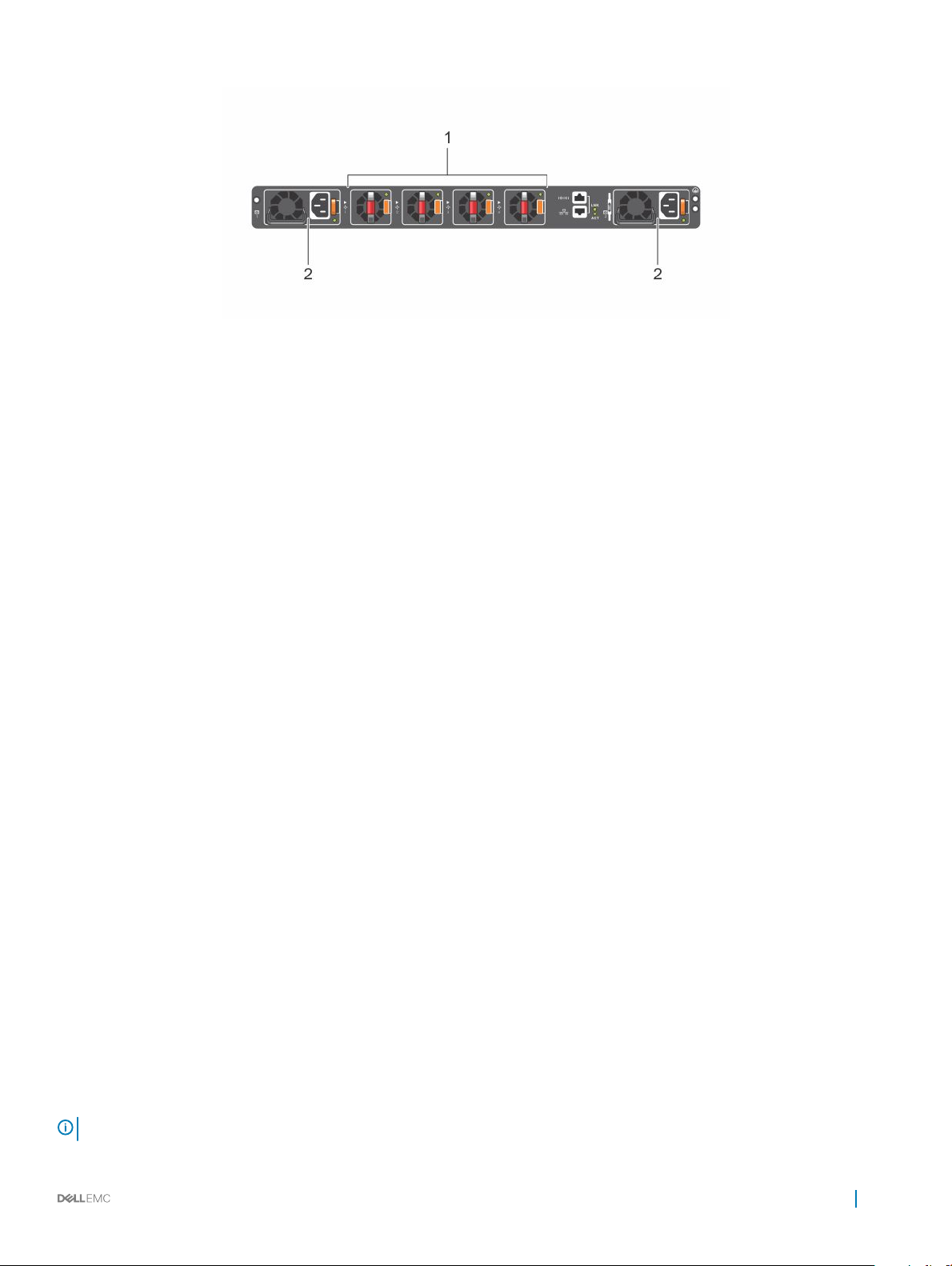
Figure 4. S4100–ON Series PSU-side view
1 Four hot-swappable fan units 2 Two hot-swappable PSUs with integrated fans
Features
The S4100–ON Series (S4128F-ON and S4148F-ON) oers the following features:
• S4128F-ON: 28 xed 10GbE SFP+ ports, 2 xed 100GbE QSFP28 ports
• S4148F-ON: 48 xed 10GbE SFP+ ports, 2 xed QSFP+ ports, 4 xed 100GbE QSFP28 ports
• One MicroUSB-B serial console management port
• One RJ-45 serial console management port
• One universal serial bus (USB) Type-A port for more le storage
• One 2 Core Rangeley C2338 central processing unit (CPU), with 4GB DDR3 SDRAM and one 16 GB mSATA/M.2 SSD module
• Seven-segment stacking indicator
• Temperature monitoring
• Real time clock (RTC) support
• Hot-plug redundant power supplies
• Removable fans
• Standard 1U chassis
Physical dimensions
The S4100–ON Series (S4128F-ON and S4148F-ON), has the following physical dimensions:
• 434 x 460 x 43.5 mm (W x D x H)
• 17.1 x 18.1 x 1.71 inches (W x D x H)
• Fan handle is 21 mm (0.82 inch) deep
• Power supply unit (PSU) and fan module handle: 40 mm—1.57 inches
System status
View the S4100–ON Series (S4128F-ON and S4148F-ON) status information using the light emitting diodes (LEDs).
LED display
The S4100–ON Series (S4128F-ON and S4148F-ON) contains LED displays on the I/O side and PSU side of the switch.
: If you are using third-party software, for more LED information, see their operating software documentation.
NOTE
S4100–ON Series switch 9
LED behavior
The following S4100–ON Series switch LED behavior displays during open networking installation environment (ONIE) operations:
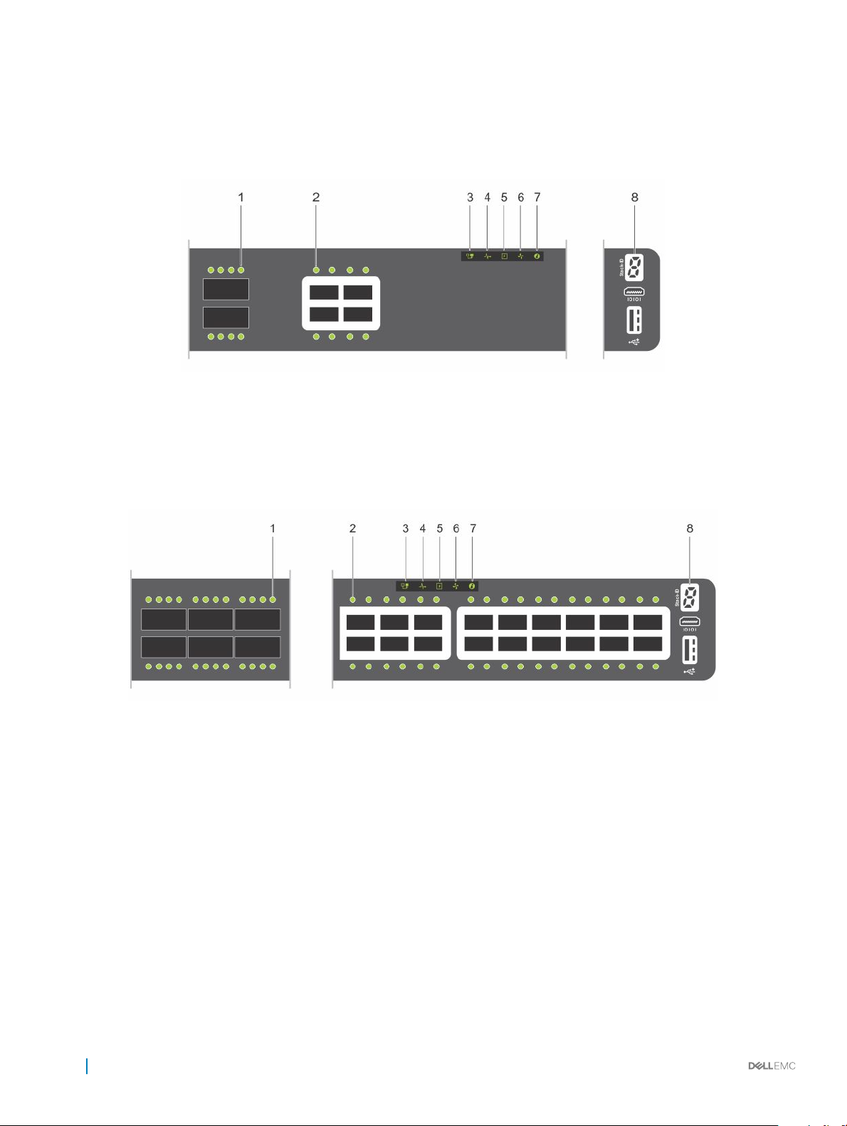
Figure 5. S4128F-ON I/O-side LEDs
1 QSFP28 port activity LEDs 2 Link (left), activity (right) port LEDs
3 Master LED 4 System LED
5 Power LED 6 Fan LED
7 Locator LED/System beacon 8 Stack ID
Figure 6. S4148F-ON I/O-side LEDs
1
QSFP28 port activity LEDs 2 Link/activity port LEDs
3 Master LED 4 System LED
5 Power LED 6 Fan LED
7 Locator LED/System beacon 8 Stack ID
10 S4100–ON Series switch
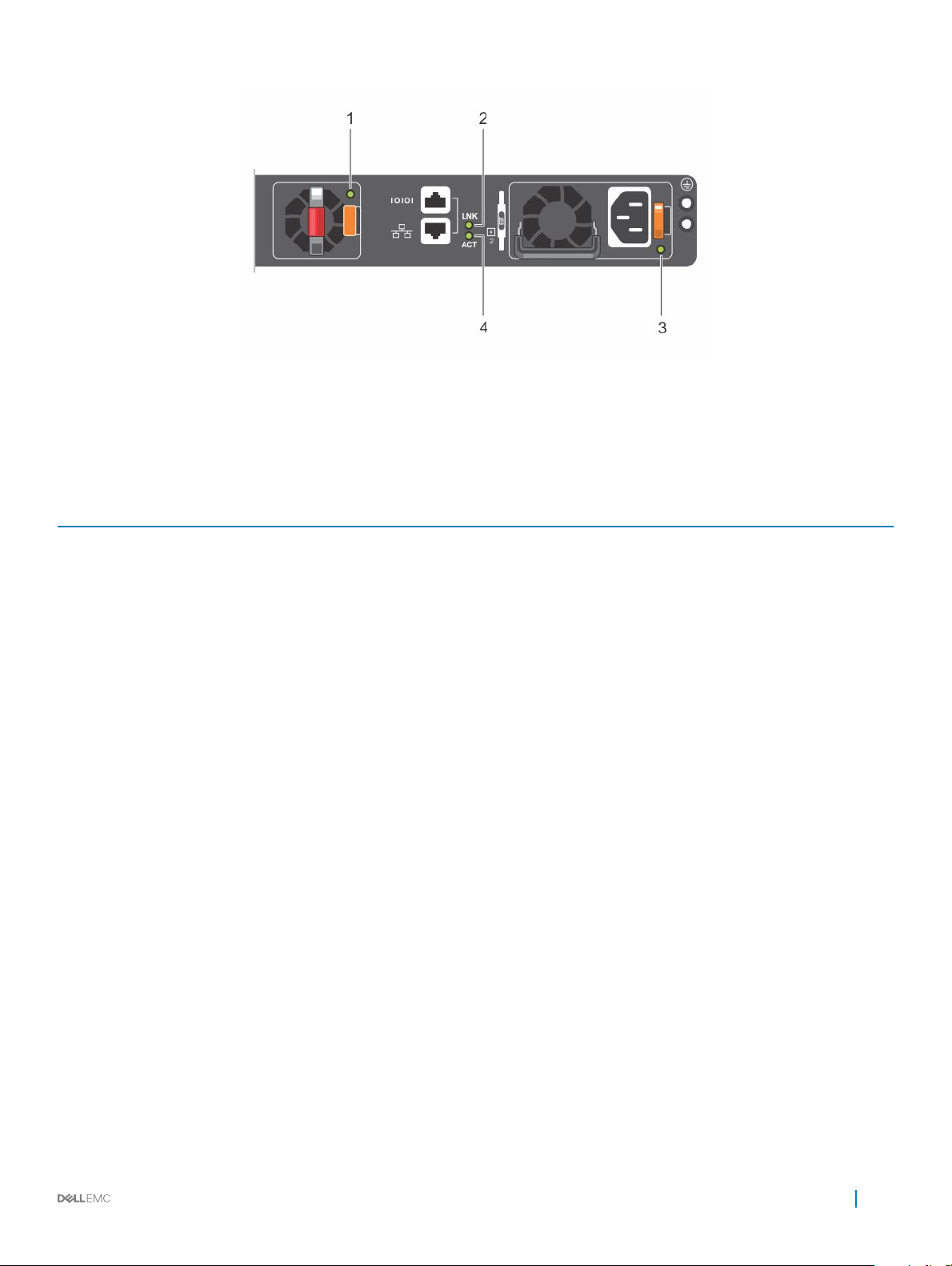
Figure 7. S4100-ON Series PSU-side LEDs
1 Fan LED 2 Link LED
3 PSU LED 4 Activity LED
Table 3. S4100–ON Series LED behavior
LED Description
System Status/Health LED
Power LED
Master LED
FAN LED
PSU LED
• Solid green—Normal operation
• Blinking green—Booting
• Solid yellow—Critical system error
• Blinking yellow—Noncritical system error, fan failure, or power
supply failure
• O—No power
• Solid green—Normal operation
• Solid yellow—POST is in process
• Blinking yellow—Power Supply failure
• O—Switch is in Stacking Slave mode
• Solid green—Switch is in Stacking Master or Standalone mode
• O—No power
• Solid green—Normal operation; fan powered and running at the
expected RPM
• Solid yellow—Fan failed—including incompatible airow
direction when you insert the PSU or fan trays with diering
airows
• O—No power
• Solid green—Normal operation
• Solid yellow—Power supply critical event causing a shutdown.
• Blinking yellow—PSU warning event; power continues to
operate
• Blinking green, 1.0 Hz—Standby mode
• Blinking green, 0.5 Hz—Ac power cord unplugged
Locator LED/System Beacon
• O—Locator function is disabled
S4100–ON Series switch 11

LED Description
• Blinking blue—Locator function is enabled
7-Segment LED for stacking
Table 4. System management Ethernet port LEDs
LED Description
Link LED
Activity LED
Table 5. SFP+ port LEDs
LED Description
Link LED
• O—No power
• Solid green—Hex digit representing the stack unit ID
• O—No link
• Solid green—Link operating at a maximum speed—
autonegotiated/forced or 1G port
• Solid yellow—Link operating at a lower speed—
autonegotiated/forced or 10/100M port
• O—No link
• Flashing green—Port activity
• O—No link
• Solid green—Link operating at maximum speed—10G port
• Solid yellow—Link operating at a lower speed—1G port
• Flashing yellow, 1 second on/o—Port beacon
Activity LED
NOTE: There are four LEDs for each QSFP+ and QSFP28 port. For each port, 100 GbE or 40 GbE uses only one LED, 2x50 GbE
uses two LEDs, and 4x25 GbE or 4x10 GbE uses all four LEDs.
Table 6. QSFP28 port LEDs
LED Description
Link/Activity LED
• O—No link
• Flashing green—Port activity
• O—No link
• Solid green—Link operating at maximum speed—100G for
QSFP28 port
• Flashing green—Link activity operating at maximum speed—
100G port
• Solid yellow—Link operating at a lower speed—40G or 10G
port
• Flashing yellow—Port activity at a lower speed—40G or 10G
port
• Flashing yellow, 1 second on/o—Port beacon
12 S4100–ON Series switch

Table 7. QSFP28 port LEDs: 4x25G or 4x10G mode
LED Description
Link/Activity LED
Table 8. QSFP28 port LEDs: 2x50G mode
LED Description
Link/Activity LED
Table 9. QSFP+ port LEDs
LED Description
Link/Activity LED
• O—No link
• Solid green—Link operating at maximum speed—4x25G port
• Flashing green—Link activity operating at maximum speed—
4x25G port
• Solid yellow—Link operating at a lower speed—4x10G port
• Flashing yellow—Port activity at a lower speed—4x10G port
• Flashing yellow, 1 second on/o—Port beacon
• O—No link
• Solid yellow—Link operating at a lower speed—2x50G port
• Flashing yellow—Link activity at a lower speed—2x50G port
• Flashing yellow, 1 second on/o—Port beacon
• O—No link
• Solid green—Link operating at maximum speed—40G port
• Flashing green—Link activity operating at maximum speed—
40G port
• Solid yellow—Link operating at a lower speed—40G port
• Flashing yellow—Link activity at a lower speed—40G port
• Flashing yellow, 1 second on/o—Port beacon
Table 10. QSFP+ port LEDs: 4x10G/1G mode
LED Description
Link/Activity LED—4x10G mode
• O—No link
• Solid green—Link operating at maximum speed—10G port
• Flashing green—Link activity operating at maximum speed—
10G port
• Solid yellow—Link operating at a lower speed—1G port
• Flashing yellow—Link activity at a lower speed—1G port
• Flashing yellow, 1 second on/o—Port beacon
Prerequisites
The following is a list of required and optional components for the S4100–ON Series (S4128F-ON and S4148F-ON) switch:
: Detailed installation instructions are provided in the Site preparations and S4100-ON Series installation sections.
NOTE
S4100–ON Series switch 13

• S4100–ON Series (S4128F-ON or S4148F-ON) switch, or multiple switches, if stacking
• AC country- and regional-specic cables to connect the AC power source to each of the switches' AC power supplies
• Mounting brackets for rack installation, included
• Screws for rack installation
• #1 and #2 Phillips screwdrivers, not included
• Torx screwdriver, not included
• Ground cable screws, included
• Copper or ber cables
Other optional components are:
• Ground cable and lug for the frame-end of the ground cable
• Extra power supply unit
• Extra fan module
• Extra mounting brackets if installing in a four-post rack or cabinet
S4100–ON Series congurations
The S4100–ON Series (S4128F-ON and S4148F-ON) switches are available in several dierent congurations.
All S4100–ON Series switches include the following congurations:
• Fan with airow from the I/O side to the PSU side—normal
• Fan with airow from the PSU side to the I/O side—reverse
• AC power supply with airow from the I/O side to the PSU side—normal
• AC power supply with airow from the PSU side to the I/O side—reverse
• DC power supply with airow from the I/O side to the PSU side—normal
• DC power supply with airow from the PSU side to the I/O side—reverse
The following table lists each S4100-ON Series switch conguration:
Table 11. S4100–ON Series
S4100F–ON Series
Switch
S4128F-ON AC or
DC Normal airow
S4128F-ON AC or
DC Reverse airow
S4148F-ON AC or
DC Normal airow
S4148F-ON AC or
DC Reverse airow
congurations
Conguration
28 xed SFP+ ports, 2 xed QSFP28 ports, 7-segment stacking indicator, 1 micro-USB-B
console port, 1 USB type-A port, 1 RJ-45 10/100/1000 Base-T Ethernet management port,
2 AC or DC PSUs, and 4 fan trays.
28 xed SFP+ ports, 2 xed QSFP28 ports, 7-segment stacking indicator, 1 micro-USB-B
console port, 1 USB type-A port, 1 RJ-45 10/100/1000 Base-T Ethernet management port,
2 AC or DC PSUs, and 4 fan trays.
48 xed SFP+ ports, 2 xed QSFP+ ports, 4 xed QSFP28 ports, 7-segment stacking
indicator, 1 micro-USB-B console port, 1 USB type-A port, 1 RJ-45 10/100/1000 Base-T
Ethernet management port, 2 AC or DC PSUs, and 4 fan trays.
48 xed SFP+ ports, 2 xed QSFP+ ports, 4 xed QSFP28 ports, 7-segment stacking
indicator, 1 micro-USB-B console port, 1 USB type-A port, 1 RJ-45 10/100/1000 Base-T
Ethernet management port, 2 AC or DC PSUs, and 4 fan trays.
14 S4100–ON Series switch
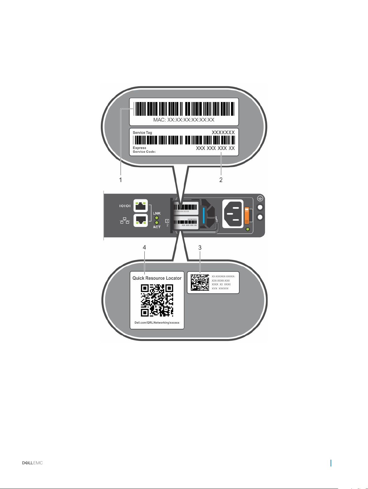
Luggage tag
The S4100–ON Series (S4128F-ON and S4148F-ON) switch has a pull-out tag, known as a luggage tag, on the PSU-side of the switch.
The front of the luggage tag includes switch ID information. The back of the luggage tag includes a QRL that takes you to a How-To site
where you watch videos about racking the switch, replacing components, conguring port channels, and so on.
Figure 8. S4100–ON Series luggage tag
Front: MAC address 2 Front: Service tag and Express service code
1
3 Back: Quick resource locator (QRL) 4 Back: QRL
S4100–ON Series switch 15
 Loading...