

Page 1

Dell EMC PowerEdge R7525
Installation and Service Manual
Reg ula tor y M ode l: E68 S
Reg ula tor y T ype : E 68S 001
Mar ch 202 1
Rev . A 09
Page 2

Notes, cautions, and warnings
NOTE: A NOTE indicates important information that helps you make better use of your product.
CAUTION: A CAUTION indicates either potential damage to hardware or loss of data and tells you how to avoid
the problem.
WARNING: A WARNING indicates a potential for property damage, personal injury, or death.
© 2020 2021 Dell Inc. or its subsidiaries. All rights reserved. Del l, EMC , and other trademarks are trademarks of Dell Inc. or its subsidiar ies .
Other trademarks may be trademarks of their respective owners.
Page 3

Contents
Chapter 1: About this document.................................................................................................... 7
Chapter 2: System overview..........................................................................................................8
Front view of the system...................................................................................................................................................8
Left control panel view................................................................................................................................................ 11
Right control panel view............................................................................................................................................. 12
Rear view of the system.................................................................................................................................................. 13
Inside the system ..............................................................................................................................................................16
Locating the Express Service Code and Service Tag............................................................................................... 17
System information label.................................................................................................................................................. 18
Rail sizing and rack compatibility matrix.......................................................................................................................21
Chapter 3: Initial system setup and configuration........................................................................22
Setting up the system......................................................................................................................................................22
iDRAC configuration......................................................................................................................................................... 22
Options to set up iDRAC IP address....................................................................................................................... 22
Options to log in to iDRAC........................................................................................................................................ 23
Resources to install operating system......................................................................................................................... 24
Options to download firmware ................................................................................................................................24
Options to download and install OS drivers .........................................................................................................24
Downloading drivers and firmware..........................................................................................................................25
Chapter 4: Installing and removing system components.............................................................. 26
Safety instructions............................................................................................................................................................26
Before working inside your system............................................................................................................................... 27
After working inside your system.................................................................................................................................. 27
Recommended tools......................................................................................................................................................... 27
Cable routing...................................................................................................................................................................... 28
RIO card...............................................................................................................................................................................33
Removing the Rear Input Output (RIO) card....................................................................................................... 33
Installing the RIO card................................................................................................................................................ 34
Optional front bezel.......................................................................................................................................................... 35
Removing the front bezel.......................................................................................................................................... 35
Installing the front bezel............................................................................................................................................ 36
System cover......................................................................................................................................................................37
Removing the system cover..................................................................................................................................... 37
Installing the system cover....................................................................................................................................... 38
Drive backplane cover......................................................................................................................................................39
Removing the drive backplane cover..................................................................................................................... 39
Installing the drive backplane cover........................................................................................................................40
Control panel....................................................................................................................................................................... 41
Removing the right control panel............................................................................................................................. 41
Installing the right control panel.............................................................................................................................. 42
Removing the left control panel...............................................................................................................................43
Contents 3
Page 4

Installing the left control panel................................................................................................................................. 44
Air shroud............................................................................................................................................................................ 46
Removing the air shroud............................................................................................................................................46
Installing the air shroud..............................................................................................................................................46
Removing the GPU air shroud..................................................................................................................................47
Installing the GPU air shroud.................................................................................................................................... 48
Removing the GPU air shroud top cover...............................................................................................................49
Installing the GPU air shroud top cover.................................................................................................................50
Cooling fan...........................................................................................................................................................................51
Removing the cooling fan cage assembly ............................................................................................................. 51
Installing the cooling fan cage assembly................................................................................................................52
Removing a cooling fan..............................................................................................................................................53
Installing a cooling fan................................................................................................................................................ 54
Side wall brackets............................................................................................................................................................. 55
Removing the side wall bracket............................................................................................................................... 55
Installing the side wall bracket................................................................................................................................. 56
Drives................................................................................................................................................................................... 57
Removing a drive blank.............................................................................................................................................. 57
Installing a drive blank................................................................................................................................................ 58
Removing the drive carrier........................................................................................................................................58
Installing the drive carrier..........................................................................................................................................59
Removing the drive from the drive carrier............................................................................................................60
Installing the drive into the drive carrier.................................................................................................................61
Drive backplane..................................................................................................................................................................62
Drive backplane............................................................................................................................................................62
Removing the drive backplane ................................................................................................................................ 64
Installing the drive backplane................................................................................................................................... 65
Rear drive cage..................................................................................................................................................................66
Removing the rear drive cage.................................................................................................................................. 66
Installing the rear drive cage.....................................................................................................................................67
Front PERC module.......................................................................................................................................................... 68
Removing the front mounting front PERC module............................................................................................. 68
Installing the front mounting front PERC module............................................................................................... 69
Removing the rear mounting front PERC module............................................................................................... 70
Installing the rear mounting front PERC module.................................................................................................. 71
System memory................................................................................................................................................................. 72
System memory guidelines........................................................................................................................................ 72
General memory module installation guidelines.................................................................................................... 74
Removing a memory module..................................................................................................................................... 76
Installing a memory module....................................................................................................................................... 77
Processor and heat sink...................................................................................................................................................79
Removing a heat sink..................................................................................................................................................79
Removing the liquid cooling heat sink modules.................................................................................................... 80
Removing the processor.............................................................................................................................................81
Installing the processor.............................................................................................................................................. 83
Installing the heat sink................................................................................................................................................85
Installing the liquid cooling heat sink....................................................................................................................... 87
Expansion cards and expansion card risers.................................................................................................................88
Expansion card installation guidelines.................................................................................................................... 89
Removing the expansion card risers...................................................................................................................... 118
4
Contents
Page 5

Installing the expansion card risers........................................................................................................................ 121
Removing expansion card from the expansion card riser................................................................................ 123
Installing an expansion card into the expansion card riser...............................................................................124
Removing the full length expansion card risers..................................................................................................126
Installing the full length expansion card risers.................................................................................................... 128
Removing a GPU........................................................................................................................................................ 130
Installing a GPU.......................................................................................................................................................... 133
Optional serial COM port............................................................................................................................................... 135
Removing the serial COM port............................................................................................................................... 135
Installing the serial COM port................................................................................................................................. 137
Optional IDSDM module................................................................................................................................................. 138
Removing the IDSDM module................................................................................................................................. 138
Installing the IDSDM module................................................................................................................................... 139
MicroSD card....................................................................................................................................................................140
Removing the MicroSD card................................................................................................................................... 140
Installing the MicroSD card...................................................................................................................................... 141
M.2 SSD module...............................................................................................................................................................142
Removing the M.2 SSD module..............................................................................................................................142
Installing the M.2 SSD module................................................................................................................................ 143
BOSS S2 card (optional)................................................................................................................................................144
Removing the BOSS card filler............................................................................................................................... 144
Installing the BOSS card filler................................................................................................................................. 145
Removing the BOSS S2 controller card module................................................................................................ 146
Installing the BOSS S2 controller card module................................................................................................... 147
System battery ................................................................................................................................................................149
Replacing the system battery................................................................................................................................. 149
Optional internal USB card.............................................................................................................................................151
Removing the internal USB card.............................................................................................................................151
Installing the internal USB card.............................................................................................................................. 152
Intrusion switch module................................................................................................................................................. 153
Removing the intrusion switch module................................................................................................................ 153
Installing the intrusion switch module...................................................................................................................154
Optional OCP card.......................................................................................................................................................... 155
Removing the OCP card.......................................................................................................................................... 155
Installing the OCP card.............................................................................................................................................157
Power supply unit............................................................................................................................................................ 158
Hot spare feature...................................................................................................................................................... 158
Removing a power supply unit blank.....................................................................................................................159
Installing a power supply unit blank....................................................................................................................... 159
Removing a power supply unit................................................................................................................................159
Installing a power supply unit.................................................................................................................................. 160
Trusted Platform Module............................................................................................................................................... 161
Upgrading the Trusted Platform Module..............................................................................................................161
Initializing TPM for users......................................................................................................................................... 162
Initializing the TPM 1.2 for users............................................................................................................................162
Initializing the TPM 2.0 for users...........................................................................................................................162
System board....................................................................................................................................................................163
Removing the system board................................................................................................................................... 163
Installing the system board......................................................................................................................................164
Restoring Service Tag using Easy Restore..........................................................................................................165
Contents
5
Page 6

LOM card and rear I/O board.......................................................................................................................................166
Removing the LOM card and rear I/O board......................................................................................................166
Installing the LOM card and rear I/O board........................................................................................................ 167
Chapter 5: Upgrade Kits............................................................................................................ 169
BOSS S2 kit...................................................................................................................................................................... 169
GPU kit............................................................................................................................................................................... 172
IDSDM kit...........................................................................................................................................................................176
Internal USB card kit....................................................................................................................................................... 177
Serial COM port kit..........................................................................................................................................................177
Chapter 6: Jumpers and connectors........................................................................................... 178
System board connectors.............................................................................................................................................. 178
System board jumper settings......................................................................................................................................180
Disabling a forgotten password....................................................................................................................................180
Chapter 7: System diagnostics and indicator codes....................................................................182
Status LED indicators..................................................................................................................................................... 182
System health and system ID indicator codes..........................................................................................................183
iDRAC Quick Sync 2 indicator codes.......................................................................................................................... 183
iDRAC Direct LED indicator codes.............................................................................................................................. 184
LCD panel.......................................................................................................................................................................... 184
Viewing Home screen............................................................................................................................................... 185
Setup menu................................................................................................................................................................. 185
View menu................................................................................................................................................................... 186
NIC indicator codes.........................................................................................................................................................186
Power supply unit indicator codes............................................................................................................................... 187
Drive indicator codes...................................................................................................................................................... 189
Using system diagnostics.............................................................................................................................................. 189
Dell Embedded System Diagnostics...................................................................................................................... 189
Chapter 8: Getting help.............................................................................................................. 191
Recycling or End-of-Life service information............................................................................................................191
Contacting Dell..................................................................................................................................................................191
Accessing system information by using QRL.............................................................................................................191
Quick Resource Locator for PowerEdge R7525 system..................................................................................192
Receiving automated support with SupportAssist ................................................................................................. 192
Chapter 9: Documentation resources......................................................................................... 193
6
Contents
Page 7

About this document
This document provides an overview about the system, information about installing and replacing components, technical
specifications, diagnostic tools, and guidelines to be followed while installing certain components.
1
About this document 7
Page 8
System overview
The PowerEdge R7525 system is a dual socket, 2U rack server that supports:
● AMD EPYCTM 7002 and 7003 series processors
● 32 DIMM slots
● Two redundant AC or DC power supply units
● Up to 12 x 3.5-inch, 8 x 3.5-inch, or 24 x 2.5-inch, 16 x 2.5-inch, 8 x 2.5-inch, or 2 x 2.5-inch (rear), SAS, SATA, or NVMe
drives.
NOTE: For more information about how to hot swap NVMe PCIe SSD U.2 device, see the Dell Express Flash NVMe PCIe
SSD User's Guide at https://www.dell.com/support Browse all Products > Data Center Infrastructure > Storage
Adapters & Controllers > Dell PowerEdge Express Flash NVMe PCIe SSD > Documentation > Manuals and
Documents.
NOTE: All instances of SAS, SATA drives, PCIe SSDs, and NVMe are referred to as drives in this document, unless specified
otherwise.
For more information about supported drives, see the www.dell.com/poweredgemanuals section.
Topics:
• Front view of the system
• Rear view of the system
• Inside the system
• Locating the Express Service Code and Service Tag
• System information label
• Rail sizing and rack compatibility matrix
2
Front view of the system
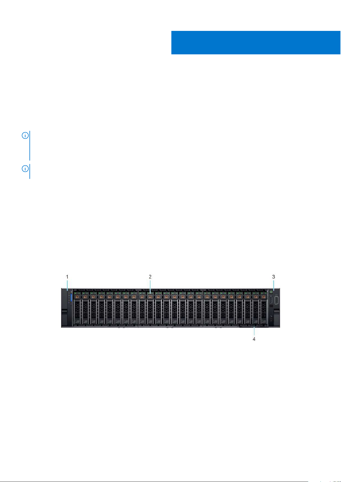
Figure 1. Front view of the 24 x 2.5-inch drive system
8 System overview
Page 9
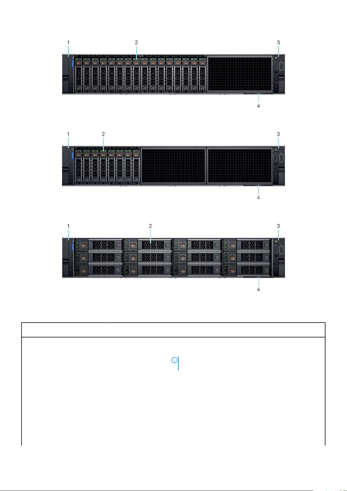
Figure 2. Front view of the 16 x 2.5-inch drive system
Figure 3. Front view of the 8 x 2.5-inch drive system
Figure 4. Front view of the 12 x 3.5-inch drive system
Table 1. Features available on the front of the system
Item Ports, panels, and
slots
1 Left control panel N/A
Icon Description
Contains the system health, system ID, status LED, and the
iDRAC Quick Sync 2 (wireless) indicator.
● Status LED: Enables you to identify any failed hardware
● Quick Sync 2 (wireless): Indicates a Quick Sync enabled
NOTE: The iDRAC Quick Sync 2 indicator is available only
on certain configurations.
components. There are up to five status LEDs and an overall
system health LED (Chassis health and system ID) bar. For
more information, see the Status LED indicators section.
system. The Quick Sync feature is optional. This feature
allows management of the system by using mobile devices
called as OpenManage Mobile (OMM) feature. Using iDRAC
Quick Sync 2 with OpenManage Mobile (OMM) aggregates
hardware or firmware inventory and various system level
diagnostic and error information that can be used in
System overview 9
Page 10
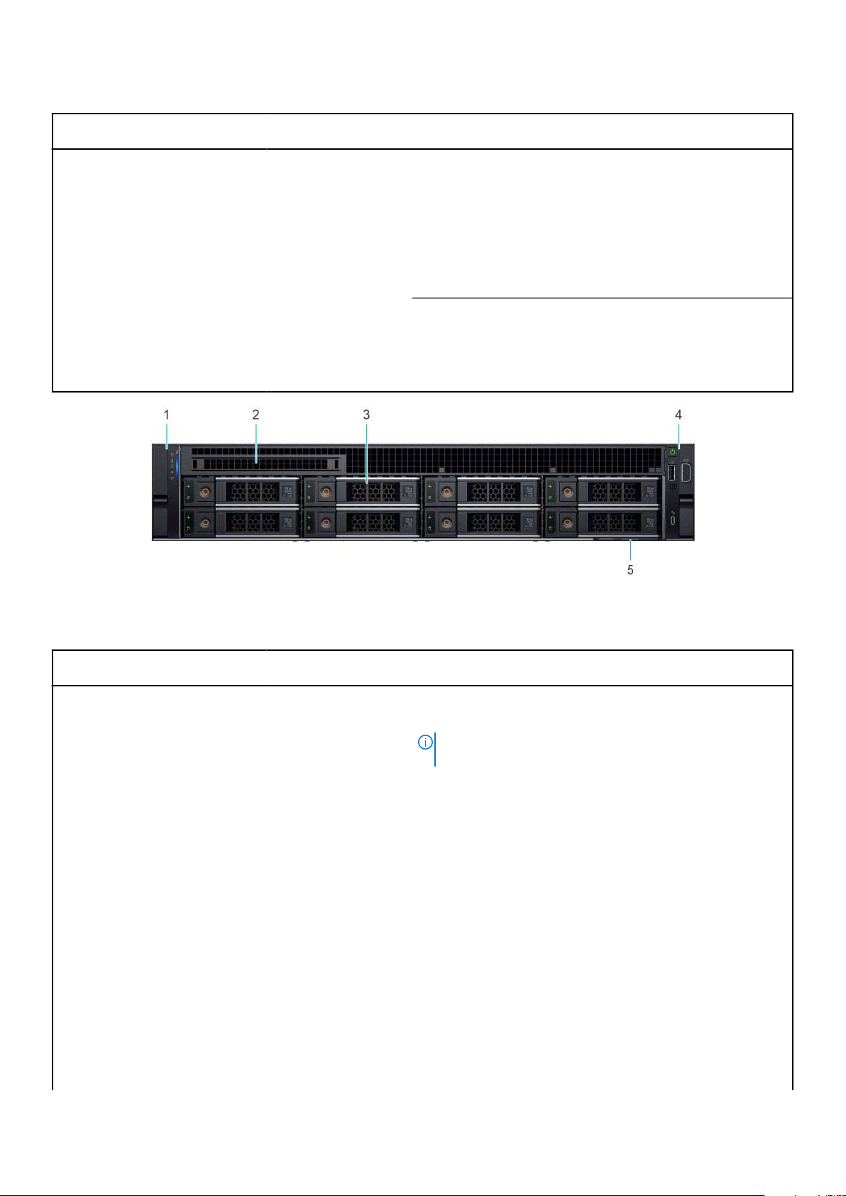
Table 1. Features available on the front of the system (continued)
Item Ports, panels, and
slots
2 Drive N/A Enables you to install drives that are supported on your system.
3 Right control panel N/A Contains the power button, USB port, iDRAC Direct micro port,
Icon Description
troubleshooting the system. For more information, see
the iDRAC User's Guide available at https://www.dell.com/
idracmanuals
For more information about drives, see the www.dell.com/
poweredgemanuals section.
and the iDRAC Direct status LED.
4 Information tag
Figure 5. Front view of the 8 x 3.5-inch drive system
The Information tag is a slide-out label panel that contains
system information such as Service Tag, NIC, MAC address,
and so on. If you have opted for the secure default access
to iDRAC, the Information tag also contains the iDRAC secure
default password.
Table 2. Features available on the front of the system
Item Ports, panels, and
slots
1 Left control panel N/A
Icon Description
Contains the system health, system ID, status LED, and the
iDRAC Quick Sync 2 (wireless) indicator.
NOTE: The iDRAC Quick Sync 2 indicator is available only
on certain configurations.
● Status LED: Enables you to identify any failed hardware
components. There are up to five status LEDs and an overall
system health LED (Chassis health and system ID) bar. For
more information, see the Status LED indicators section.
● Quick Sync 2 (wireless): Indicates a Quick Sync enabled
system. The Quick Sync feature is optional. This feature
allows management of the system by using mobile devices
called as OpenManage Mobile (OMM) feature. Using iDRAC
Quick Sync 2 with OpenManage Mobile (OMM) aggregates
hardware or firmware inventory and various system level
diagnostic and error information that can be used in
troubleshooting the system. For more information, see
the iDRAC User's Guide available at https://www.dell.com/
idracmanuals
2 Optical drive blank N/A For the 8 x 3.5-inch drive system, a optical drive bay blank is
installed.
3 Drive N/A Enables you to install drives that are supported on your system.
For more information about drives, see the www.dell.com/
poweredgemanuals section.
10 System overview
Page 11
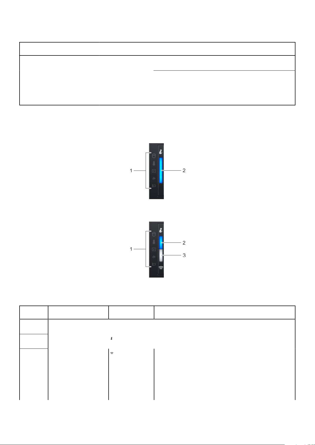
Table 2. Features available on the front of the system
Item Ports, panels, and
slots
4 Right control panel N/A Contains the power button, USB port, iDRAC Direct micro port,
Icon Description
and the iDRAC Direct status LED.
5 Information tag
For more information about the ports, see the www.dell.com/poweredgemanuals section.
The Information tag is a slide-out label panel that contains
system information such as Service Tag, NIC, MAC address,
and so on. If you have opted for the secure default access
to iDRAC, the Information tag also contains the iDRAC secure
default password.
Left control panel view
Figure 6. Left control panel without optional iDRAC Quick Sync 2 indicator
Figure 7. Left control panel with optional iDRAC Quick Sync 2 indicator
Table 3. Left control panel (continued)
Item Indicator, button, or
1 Status LED indicators N/A Indicates the status of the system. For more information, see
2
3
connector
System health and system
ID indicator
iDRAC Quick Sync
2 wireless indicator
(optional)
Icon Description
the Status LED indicators section.
Indicates the system health. For more information, see the
System health and system ID indicator codes section.
Indicates if the iDRAC Quick Sync 2 wireless option is activated.
The Quick Sync 2 feature allows management of the system
using mobile devices. This feature aggregates hardware/
firmware inventory and various system level diagnostic/error
information that can be used in troubleshooting the system.
You can access system inventory, Dell Lifecycle Controller
logs or system logs, system health status, and also configure
iDRAC, BIOS, and networking parameters. You can also launch
System overview 11
Page 12
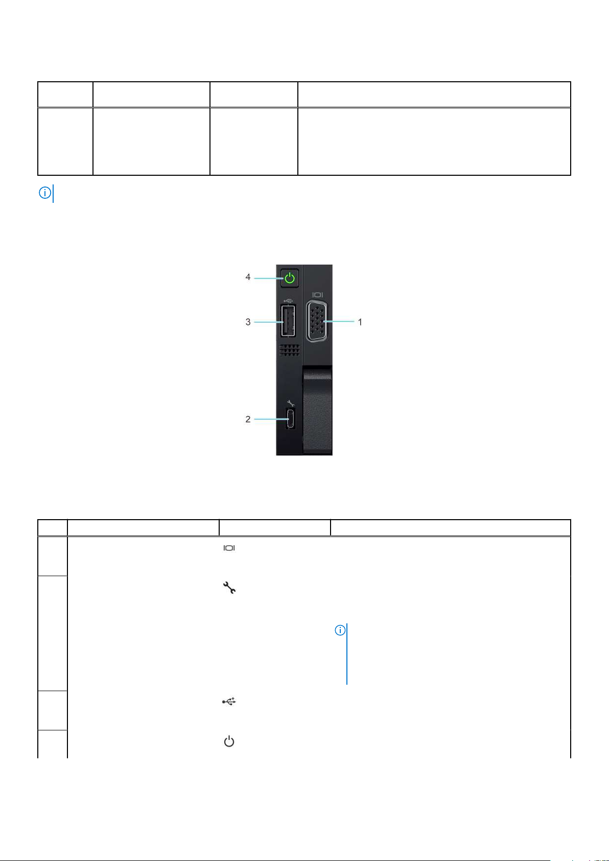
Table 3. Left control panel
Item Indicator, button, or
connector
NOTE: For more information about the indicator codes, see the System diagnostics and indicator codes section.
Icon Description
the virtual Keyboard, Video, and Mouse (KVM) viewer and
virtual Kernel-based Virtual Machine (KVM), on a supported
mobile device. For more information, see the Integrated Dell
Remote Access Controller User's Guide at www.dell.com/
poweredgemanuals
Right control panel view
Figure 8. Right control panel view
Table 4. Right control panel (continued)
Item Indicator or button Icon Description
1 VGA port Enables you to connect a display device to the
system. For more information, see the www.dell.com/
poweredgemanuals section.
iDRAC Direct port (Micro-AB
2
USB)
USB 2.0-compliant port The USB port is a 4-pin connector and 2.0-compliant.
3
Power button Indicates if the system is powered on or off. Press the
4
The iDRAC Direct port (Micro-AB USB) enables you to
access the iDRAC Direct Micro-AB features. For more
information, see the iDRAC User's Guide available at
https://www.dell.com/idracmanuals .
NOTE: You can configure iDRAC Direct by using
a USB to micro USB (type AB) cable, which
you can connect to your laptop or tablet. Cable
length should not exceed 3 feet (0.91 meters).
Performance could be affected by cable quality.
This port enables you to connect USB devices to the
system.
power button to manually power on or off the system.
12 System overview
Page 13
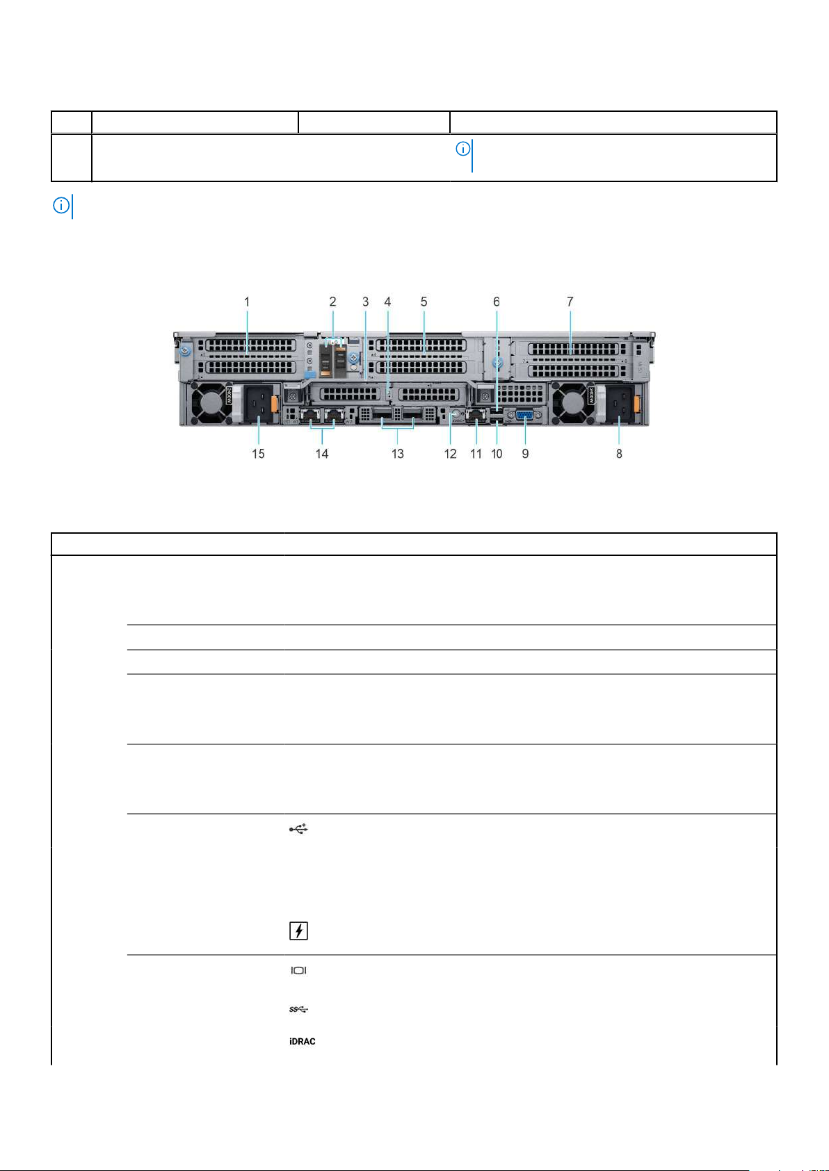
Table 4. Right control panel
Item Indicator or button Icon Description
NOTE: Press the power button to gracefully shut
down the ACPI-compliant operating system.
NOTE: For more information on the ports, see the www.dell.com/poweredgemanuals section.
Rear view of the system
Figure 9. Rear view of the system
Table 5. Rear view of the system
Item Ports, panels, or slots Icon Description
1 PCIe expansion card riser
1 (slot 1 and slot 2)
2
3
4
5
6
7 PCIe expansion card riser
8 Power supply unit (PSU
BOSS S2 Card (optional) N/A This slot supports the BOSS S2 module
Rear Handle N/A To lift the system.
PCIe expansion card riser
2 (slot 3 and slot 6)
PCIe expansion card riser
3 (slot 4 and slot 5)
USB 2.0 port (1) This port is USB 2.0-compliant.
4 (slot 7 and slot 8)
2)
N/A The expansion card riser enables you to connect PCI Express
expansion cards. For more information on the expansion
cards that are supported on your system, see www.dell.com/
poweredgemanuals section.
N/A The expansion card riser enables you to connect PCI Express
expansion cards. For more information on the expansion
cards that are supported on your system, see www.dell.com/
poweredgemanuals section.
N/A The expansion card riser enables you to connect PCI Express
expansion cards. For more information on the expansion
cards that are supported on your system, see www.dell.com/
poweredgemanuals section.
N/A The expansion card riser enables you to connect PCI Express
expansion cards. For more information on the expansion
cards that are supported on your system, see www.dell.com/
poweredgemanuals section.
For more information about the PSU configurations, see the
www.dell.com/poweredgemanuals section.
9
10 USB 3.0 port (1) This port is USB 3.0-compliant.
11 iDRAC dedicated port Enables you to remotely access iDRAC. For more information, see
VGA port Enables you to connect a display device to the system. For more
information, see the www.dell.com/poweredgemanuals section.
the iDRAC User's Guide at www.dell.com/poweredgemanuals
System overview 13
Page 14
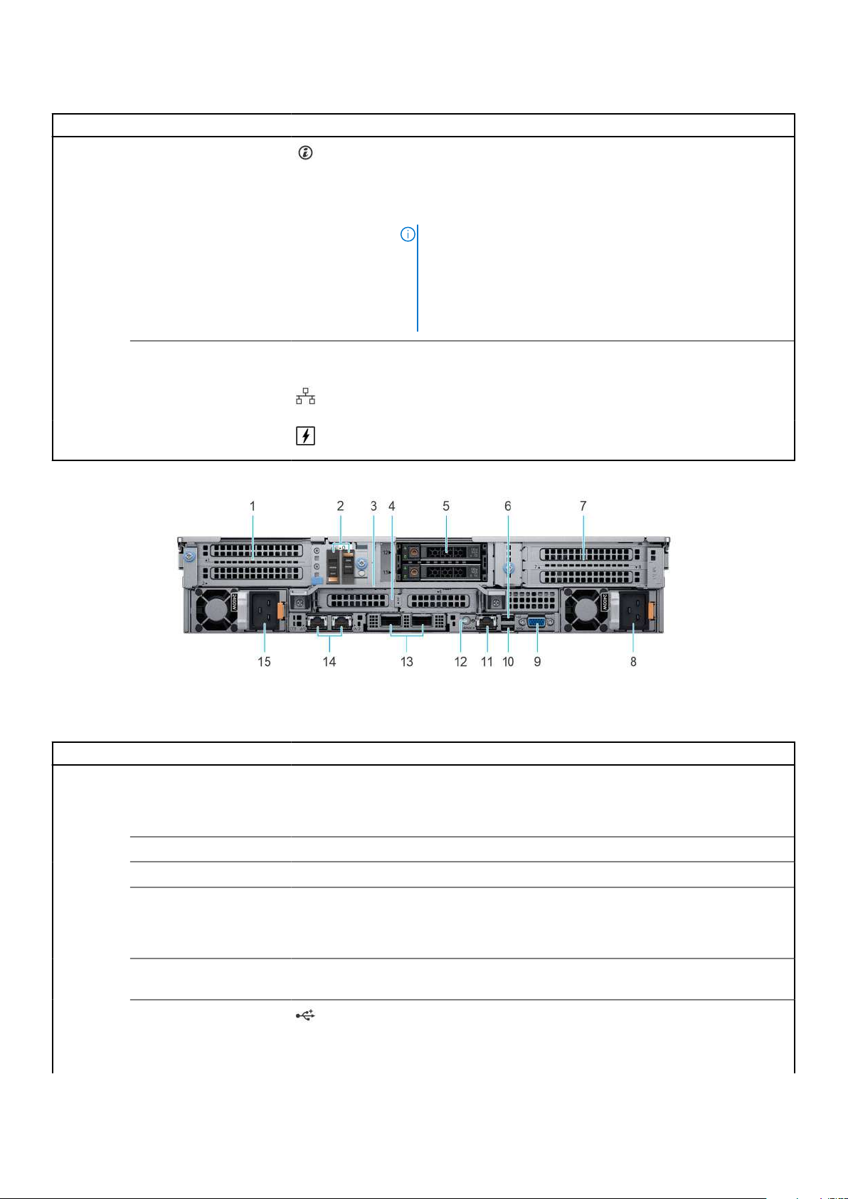
Table 5. Rear view of the system
Item Ports, panels, or slots Icon Description
12 System identification
button
Press the system ID button:
● To locate a particular system within a rack.
● To turn the system ID on or off.
To reset iDRAC, press and hold the button for more than 16
seconds.
NOTE:
● To reset iDRAC using system ID, ensure that the system ID
button is enabled in the iDRAC setup.
● If the system stops responding during POST, press and hold
the system ID button (for more than 5 seconds) to enter
the BIOS progress mode.
13
14 NIC port (1,2) The NIC ports are embedded on the LOM card that is connected to
15 Power supply unit (PSU 1) For more information about the PSU configurations, see the
For more information about the ports, see the www.dell.com/poweredgemanuals section.
Figure 10. Rear view of the system with 2 x 2.5-inch rear drive module
OCP NIC port (optional) N/A This port supports OCP 3.0. The NIC ports are integrated on the
OCP card which is connected to the system board.
the system board.
www.dell.com/poweredgemanuals section.
Table 6. Rear view of the system with 2 x 2.5-inch rear drive module (continued)
Item Ports, panels, or slots Icon Description
1 PCIe expansion card riser
1 (slot 1 and slot 2)
N/A The expansion card riser enables you to connect PCI Express
expansion cards. For more information on the expansion
cards that are supported on your system, see www.dell.com/
poweredgemanuals section.
2
3
4
5
6
7 PCIe expansion card riser
14 System overview
BOSS S2 card (optional) N/A This slot supports the BOSS S2 module
Rear Handle N/A To lift the system.
PCIe expansion card riser
2 (slot 3 and slot 6)
Rear drive module N/A Enables you to install drives that are supported on your system. For
USB 2.0 port (1) This port is USB 2.0-compliant.
4 (slot 7 and slot 8)
N/A The expansion card riser enables you to connect PCI Express
expansion cards. For more information on the expansion
cards that are supported on your system, see www.dell.com/
poweredgemanuals section.
more information about drives, see the Drives section.
N/A The expansion card riser enables you to connect PCI Express
expansion cards. For more information on the expansion
Page 15
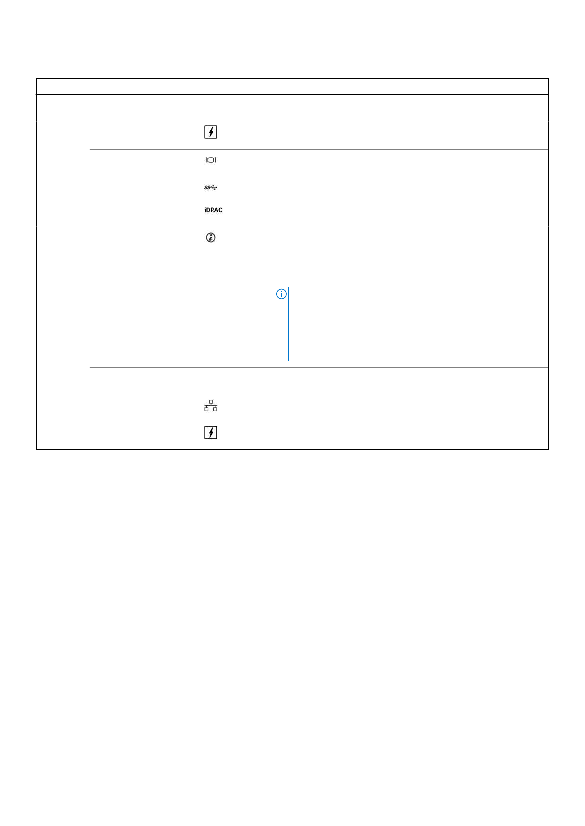
Table 6. Rear view of the system with 2 x 2.5-inch rear drive module
Item Ports, panels, or slots Icon Description
cards that are supported on your system, see www.dell.com/
poweredgemanuals section.
8 Power supply unit (PSU
2)
For more information about the PSU configurations, see the
www.dell.com/poweredgemanuals section.
9
10 USB 3.0 port (1) This port is USB 3.0-compliant.
11 iDRAC dedicated port Enables you to remotely access iDRAC. For more information, see
12 System identification
13
14 NIC port (1,2) The NIC ports are embedded on the LOM card that is connected to
15 Power supply unit (PSU 1) For more information about the PSU configurations, see the
VGA port Enables you to connect a display device to the system. For more
information, see the www.dell.com/poweredgemanuals section.
the iDRAC User's Guide at www.dell.com/poweredgemanuals
Press the system ID button:
button
OCP NIC port (optional) N/A This port supports OCP 3.0. The NIC ports are integrated on the
● To locate a particular system within a rack.
● To turn the system ID on or off.
To reset iDRAC, press and hold the button for more than 16
seconds.
NOTE:
● To reset iDRAC using system ID, ensure that the system ID
button is enabled in the iDRAC setup.
● If the system stops responding during POST, press and hold
the system ID button (for more than 5 seconds) to enter
the BIOS progress mode.
OCP card which is connected to the system board.
the system board.
www.dell.com/poweredgemanuals section.
For more information about the ports, see the www.dell.com/poweredgemanuals section.
System overview
15
Page 16
Inside the system
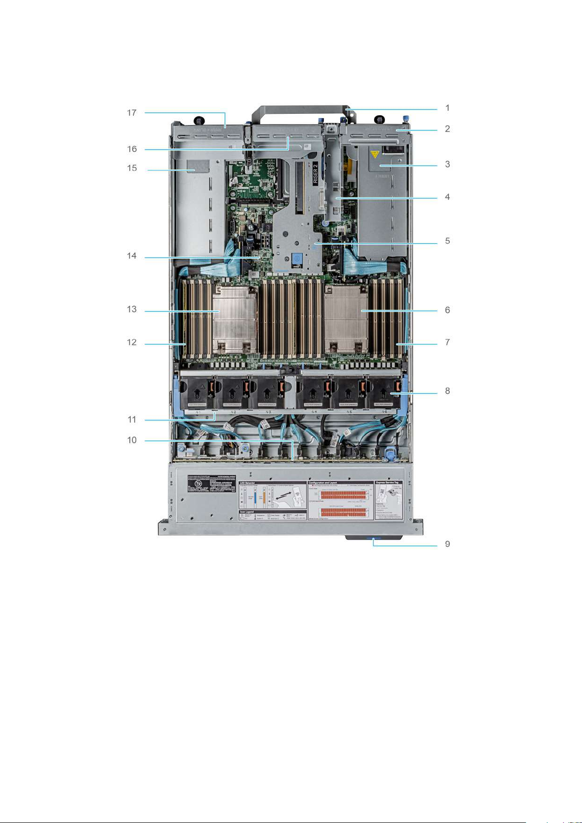
Figure 11. Inside the system
1.
Handle 2. Riser 1 blank
3. Power supply unit (PSU 1) 4. BOSS S2 card slot
5. Riser 2 6. Heat sink for processor 1
7. Memory DIMM socket for processor 1 (E,F,G,H) 8. Cooling fan assembly
9. Service tag 10. Drive backplane
11. Cooling fan cage assembly 12. Memory DIMM socket for processor 2 (A,B,C,D)
13. Heat sink for processor 2 14. System board
15. Power supply unit (PSU 2) 16. Riser 3 blank
17. Riser 4 blank
16 System overview
Page 17
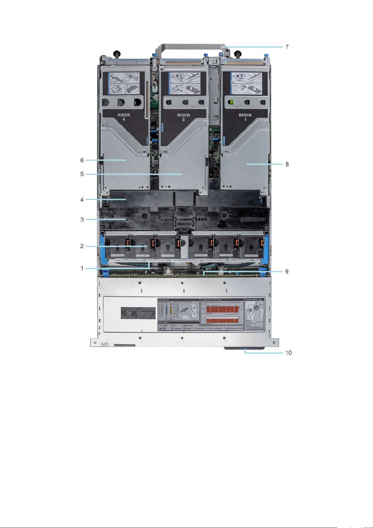
Figure 12. Inside the system with full length risers
Cooling fan cage assembly 2. Cooling fan
1.
3. GPU air shroud 4. GPU air shroud top cover
5. Riser 3 6. Riser 4
7. Handle 8. Riser 1
9. Drive backplane 10. Service tag
Locating the Express Service Code and Service Tag
The unique Express Service Code and Service Tag is used to identify the system. The information tag is located on the front of
the system that includes system information such as Service Tag, Express Service Code, Manufacture date, NIC, MAC address,
QRL label, and so on. If you have opted for the secure default access to iDRAC, the Information tag also contains the iDRAC
secure default password. If you have opted for iDRAC Quick Sync 2, the Information tag also contains the OpenManage Mobile
(OMM) label, where administrators can configure, monitor, and troubleshoot the PowerEdge servers.
System overview
17
Page 18
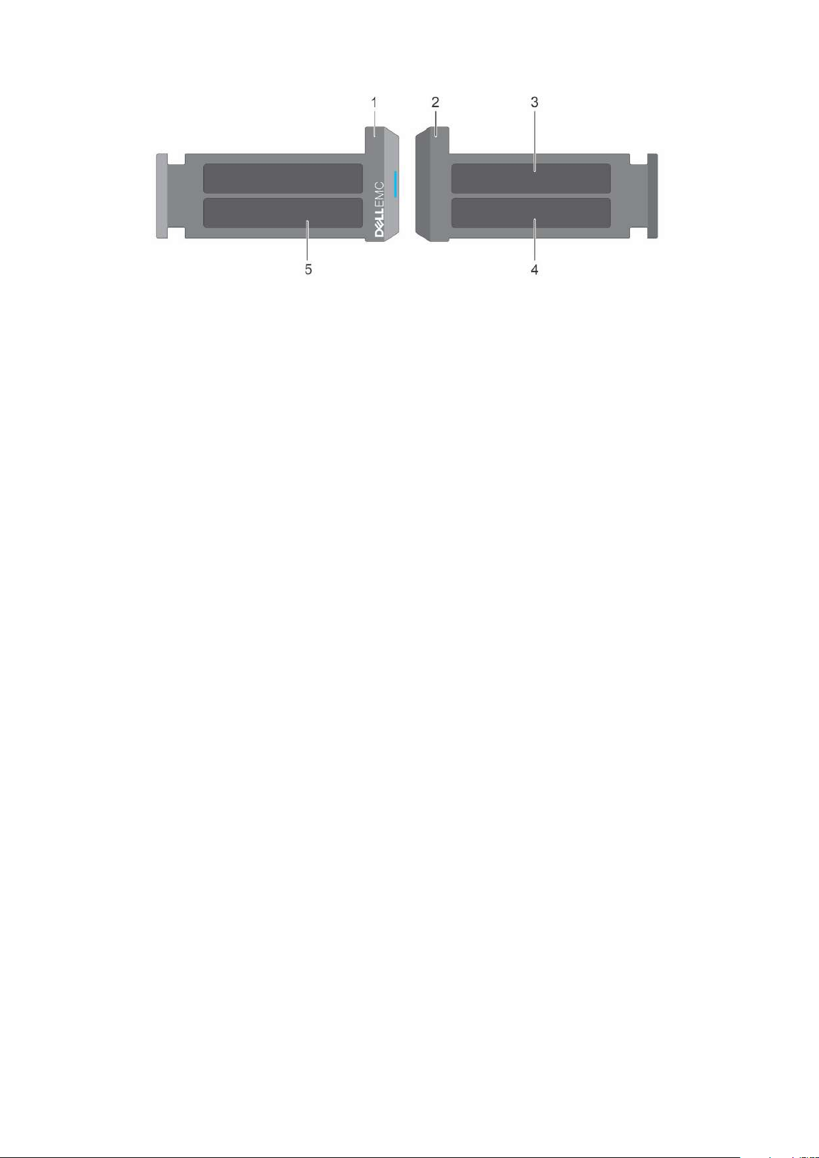
Figure 13. Locating the Express Service Code and Service tag
1. Information tag (front view) 2. Information tag (back view)
3. OpenManage Mobile (OMM) label 4. iDRAC MAC address and iDRAC secure password label
5. Service Tag, Express Service Code, QRL label
The Mini Enterprise Service Tag (MEST) label is located on the rear of the system that includes Service Tag (ST), Express
Service Code (Exp Svc Code), and Manufacture Date (Mfg. Date). The Exp Svc Code is used by Dell EMC to route support calls
to the appropriate personnel.
Alternatively, the Service Tag information is located on a label on left wall of the chassis.
System information label
The system information label is located on the back side of the system cover.
18
System overview
Page 19
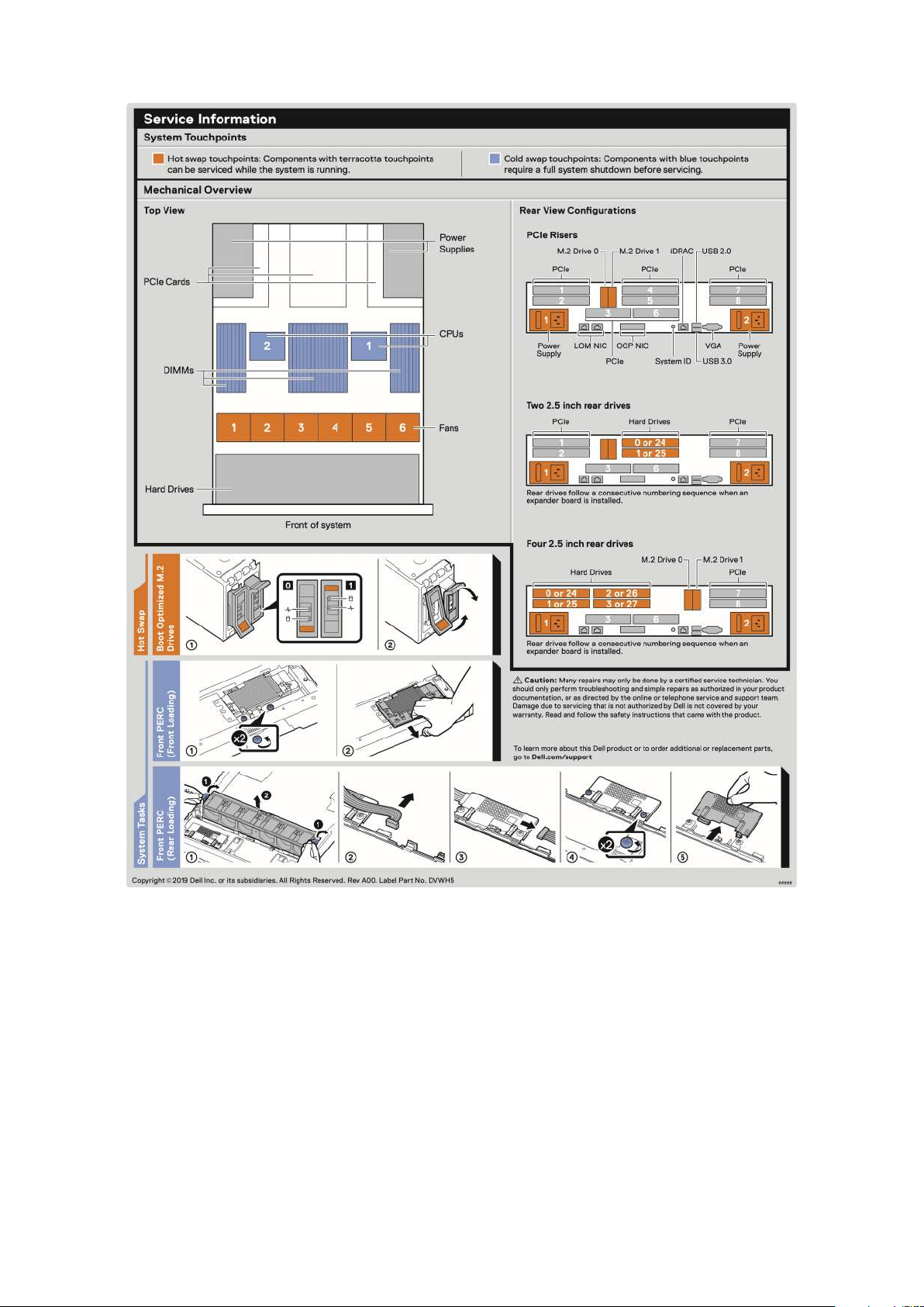
Figure 14. Service information
System overview
19
Page 20
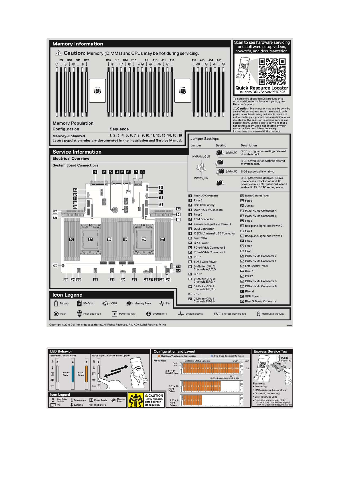
Figure 15. Memory information and system board connectors
Figure 16. LED behavior, configuration and layout, express service tag for 2.5-inch HDD system
20
System overview
Page 21
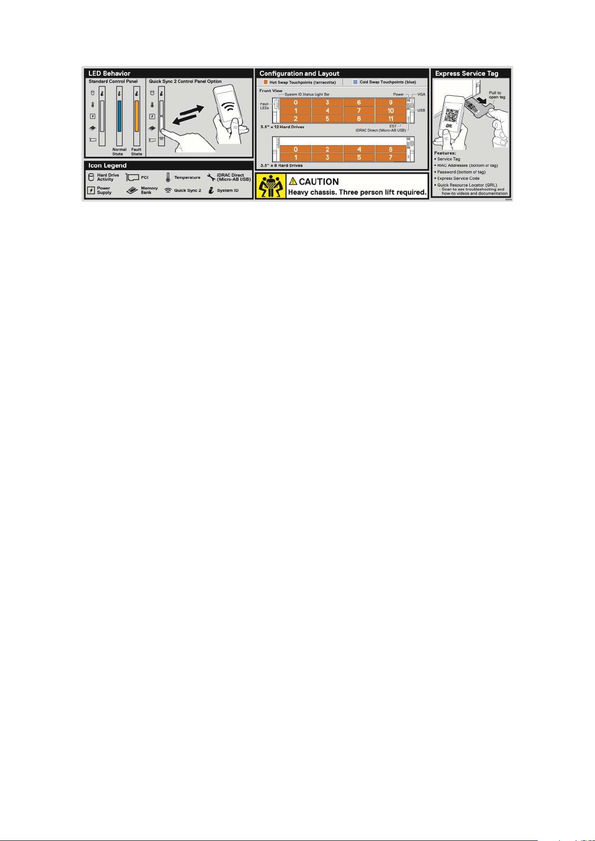
Figure 17. LED behavior, configuration and layout, express service tag for 3.5-inch HDD system
Rail sizing and rack compatibility matrix
For specific information about the rail solutions compatible with your system, see the Dell EMC Enterprise Systems
Rail Sizing and Rack Compatibility Matrix available at https://i.dell.com/sites/csdocuments/Business_solutions_engineering-
Docs_Documents/en/rail-rack-matrix.pdf.
The document provides the information that is listed below:
● Specific details about rail types and their functionalities
● Rail adjustability ranges for various rack mounting flange types
● Rail depth with and without cable management accessories
● Rack types that are supported for various rack mounting flange types
System overview
21
Page 22

Initial system setup and configuration
This section describes the tasks for initial setup and configuration of the Dell EMC system. The sections provide general steps
that you must complete to set up the system and the reference guides for detailed information.
Topics:
• Setting up the system
• iDRAC configuration
• Resources to install operating system
Setting up the system
Perform the following steps to set up the system:
Steps
1. Unpack the system.
2. Install the system into the rack. For more information see the rail installation and cable management accessory guides
relevant to your rail and cable management solution at www.dell.com/poweredgemanuals.
3. Connect the peripherals to the system and the system to the electrical outlet.
4. Power on the system by pressing the power button.
For more information about setting up the system, see the Getting Started Guide that is shipped with your system.
3
iDRAC configuration
The Integrated Dell Remote Access Controller (iDRAC) is designed to make you more productive as a system administrator
and improve the overall availability of Dell EMC servers. iDRAC alerts you to system issues, helps you to perform remote
management, and reduces the need for physical access to the system.
Options to set up iDRAC IP address
To enable communication between your system and iDRAC, you must first configure the network settings based on your
network infrastructure. The network settings option is set to DHCP, by default.
NOTE: For static IP configuration, you must request for the setting at the time of purchase.
You can set up the iDRAC IP address using one of the following interfaces. For information about how to set up iDRAC IP
address, see the documentation links provided in the table.
Table 7. Interfaces to set up iDRAC IP address
Interface Documentation links
iDRAC Settings utility Integrated Dell Remote Access Controller User's Guide at
https://www.dell.com/idracmanuals or for system specific
Integrated Dell Remote Access Controller User's Guide,
go to https://www.dell.com/poweredgemanuals > Product
Support page of your system > Manuals & documents.
NOTE: To determine the most recent iDRAC release
for your platform and for latest documentation version,
see KB article https://www.dell.com/support/article/
sln308699.
22 Initial system setup and configuration
Page 23
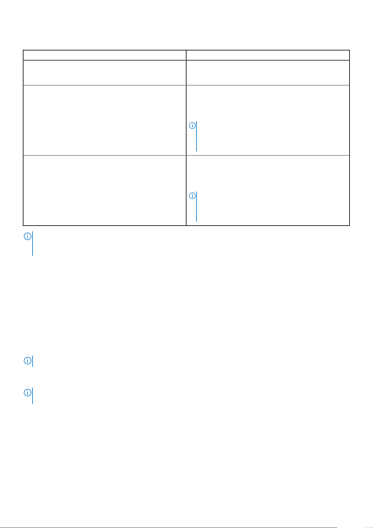
Table 7. Interfaces to set up iDRAC IP address
Interface Documentation links
OpenManage Deployment Toolkit OpenManage Deployment Toolkit User’s Guide
at www.dell.com/openmanagemanuals > OpenManage
Deployment Toolkit.
Lifecycle Controller Lifecycle Controller User’s Guide at https://www.dell.com/
idracmanuals or for system-specific Lifecycle Controller User’s
Guide, go to https://www.dell.com/poweredgemanuals >
Product Support page of your system > Manuals &
documents.
NOTE: To determine the most recent iDRAC release
for your platform and for latest documentation version,
see KB article https://www.dell.com/support/article/
sln308699.
iDRAC Direct and Quick Sync 2 (optional) Integrated Dell Remote Access Controller User's Guide at
https://www.dell.com/idracmanuals or for system specific
Integrated Dell Remote Access Controller User's Guide,
go to https://www.dell.com/poweredgemanuals > Product
Support page of your system > Manuals & documents.
NOTE: To determine the most recent iDRAC release
for your platform and for latest documentation version,
see KB article https://www.dell.com/support/article/
sln308699.
NOTE: To access iDRAC, ensure that you connect the ethernet cable to the iDRAC9 dedicated network port or use iDRAC
Direct port by using the USB cable. You can also access iDRAC through the shared LOM mode, if you have opted for a
system that has the shared LOM mode enabled.
Options to log in to iDRAC
To log in to the iDRAC Web User Interface, open a browser and enter the IP address.
You can log in to iDRAC as:
● iDRAC user
● Microsoft Active Directory user
● Lightweight Directory Access Protocol (LDAP) user
In the log in screen displayed, if you have opted for secure default access to iDRAC, enter the iDRAC secure default password
available on back side of the Information Tag. If you have not opted for secure default access to iDRAC, enter the default user
name and password – r oot and c alv in. You can also log in by using your Single Sign-On or Smart Card.
NOTE: Ensure that you change the default username and password after setting up the iDRAC IP address.
For more information about logging in to the iDRAC and iDRAC licenses, see the latest Integrated Dell Remote Access Controller
User's Guide at www.dell.com/idracmanuals.
To determine the most recent iDRAC release for your platform and for latest documentation version, see KB article
NOTE:
https://www.dell.com/support/article/sln308699.
You can also access iDRAC using command-line protocol - RACADM. For more information, see the iDRAC with Lifecycle
Controller RACADM CLI Guide available at www.dell.com/idracmanuals.
You can also access iDRAC using automation tool - Redfish API. For more information, see the iDRAC9 with Lifecycle Controller
Redfish API Guide available at https://www.dell.com/idracmanuals.
Initial system setup and configuration
23
Page 24
Resources to install operating system
If the system is shipped without an operating system, you can install a supported operating system by using one of the
resources provided in the table. For information about how to install the operating system, see the documentation links provided
in the table.
Table 8. Resources to install the operating system
Resource Documentation links
iDRAC Integrated Dell Remote Access Controller User's Guide at https://www.dell.com/idracmanuals or for
system specific Integrated Dell Remote Access Controller User's Guide, go to https://www.dell.com/
poweredgemanuals > Product Support page of your system > Manuals & documents.
NOTE: To determine the most recent iDRAC release for your platform and for latest
documentation version, see KB article at https://www.dell.com/support/article/sln308699.
Lifecycle Controller Lifecycle Controller User’s Guide at https://www.dell.com/idracmanuals or for system specific
Lifecycle Controller User’s Guide, go to https://www.dell.com/poweredgemanuals > Product
Support page of your system > Manuals & documents. Dell recommends using Lifecycle Controller
to install the OS, since all required drivers are installed to the system.
NOTE: To determine the most recent iDRAC release for your platform and for latest
documentation version, see KB article at https://www.dell.com/support/article/sln308699.
OpenManage
Deployment Toolkit
Dell certified VMware
ESXi
NOTE: For more information about Installation and How-to videos for supported operating systems on PowerEdge system
see, Supported Operating Systems for Dell EMC PowerEdge systems.
www.dell.com/openmanagemanuals > OpenManage Deployment Toolkit
www.dell.com/virtualizationsolutions
Options to download firmware
You can download firmware from the Dell support site. For information, see the Downloading drivers and firmware section.
You can also choose any one of the following options to download the firmware. For information about how to download the
firmware, see the documentation links provided in the table.
Table 9. Options to download firmware
Option Documentation link
Using Dell Remote Access Controller Lifecycle Controller
(iDRAC with LC)
Using Dell Repository Manager (DRM) www.dell.com/openmanagemanuals > Repository Manager
Using Dell Server Update Utility (SUU) www.dell.com/openmanagemanuals > Server Update Utility
Using Dell OpenManage Deployment Toolkit (DTK) www.dell.com/openmanagemanuals > OpenManage
www.dell.com/idracmanuals
Deployment Toolkit
Using iDRAC virtual media www.dell.com/idracmanuals
Options to download and install OS drivers
You can choose any one of the following options to download and install OS drivers. For information about how to download or
install OS drivers, see the documentation links provided in the table.
Table 10. Options to download and install OS drivers
24 Initial system setup and configuration
Page 25
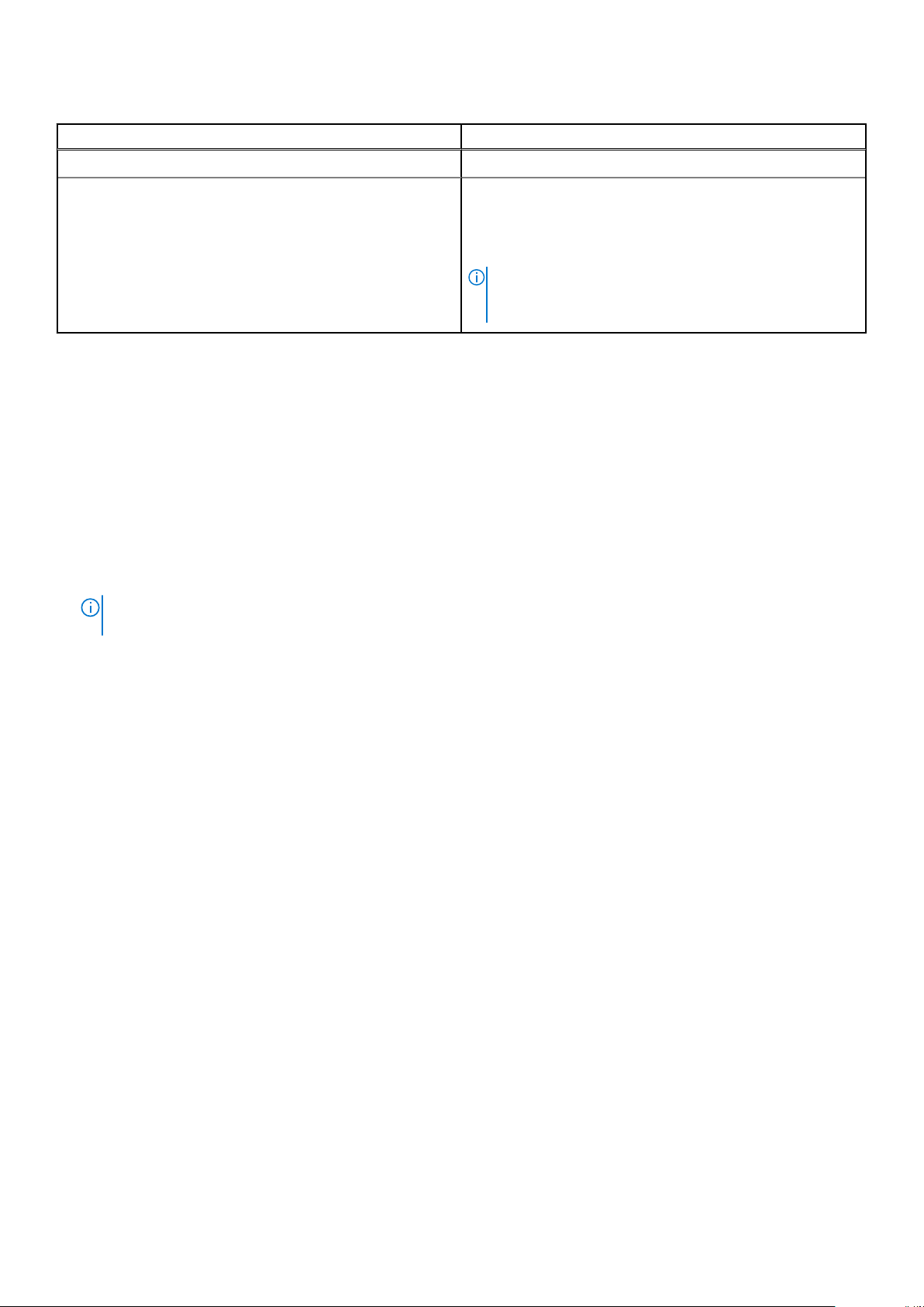
Table 10. Options to download and install OS drivers
Option Documentation
Dell EMC support site Downloading drivers and firmware section.
iDRAC virtual media Integrated Dell Remote Access Controller User's Guide at
https://www.dell.com/idracmanuals or for system specific
Integrated Dell Remote Access Controller User's Guide,
go to https://www.dell.com/poweredgemanuals > Product
Support page of your system > Manuals & documents.
NOTE: To determine the most recent iDRAC release for
your platform and for latest documentation version, see
https://www.dell.com/support/article/sln308699.
Downloading drivers and firmware
It is recommended that you download and install the latest BIOS, drivers, and systems management firmware on the system.
Prerequisites
Ensure that you clear the web browser cache before downloading the drivers and firmware.
Steps
1. Go to www.dell.com/support/drivers.
2. Enter the Service Tag of the system in the Enter a Dell Service Tag, Dell EMC Product ID or Model field, and then press
Enter.
NOTE:
If you do not have the Service Tag, select Detect PC to automatically detect the Service Tag, or click Browse
all products, and navigate to your product.
3. On the displayed product page, click Drivers & Downloads.
On the Drivers & Downloads page, all drivers that are applicable to the system are displayed.
4. Download the drivers to a USB drive, CD, DVD or local machine.
Initial system setup and configuration
25
Page 26

Installing and removing system components
Topics:
• Safety instructions
Before working inside your system
•
• After working inside your system
• Recommended tools
• Cable routing
• RIO card
• Optional front bezel
• System cover
• Drive backplane cover
• Control panel
• Air shroud
• Cooling fan
• Side wall brackets
• Drives
• Drive backplane
• Rear drive cage
• Front PERC module
• System memory
• Processor and heat sink
• Expansion cards and expansion card risers
• Optional serial COM port
• Optional IDSDM module
• MicroSD card
• M.2 SSD module
• BOSS S2 card (optional)
• System battery
• Optional internal USB card
• Intrusion switch module
• Optional OCP card
• Power supply unit
• Trusted Platform Module
• System board
• LOM card and rear I/O board
4
Safety instructions
NOTE: To avoid injury, do not lift the system on your own. Get others to assist you.
WARNING: Opening or removing the system cover while the system is turned on may expose you to a risk of
electric shock..
CAUTION: Many repairs may only be done by a certified service technician. You should only perform
troubleshooting and simple repairs as authorized in your product documentation, or as directed by the online or
telephone service and support team. Damage due to servicing that is not authorized by Dell is not covered by
your warranty. Read and follow the safety instructions that are shipped with your product.
26 Installing and removing system components
Page 27

CAUTION: To ensure proper operation and cooling, all system bays and fans must be always populated with a
component or a blank.
NOTE: It is recommended that you always use an antistatic mat and antistatic strap while working on components inside
the system.
NOTE: While replacing the hot swappable PSU, after next server boot; the new PSU automatically updates to the same
firmware and configuration of the replaced one. For more information about the Part replacement configuration, see the
Lifecycle Controller User's Guide at https://www.dell.com/idracmanuals
NOTE: While replacing faulty storage controller/FC/NIC card with the same type of card, after you power on the system;
the new card automatically updates to the same firmware and configuration of the faulty one. For more information about
the Part replacement configuration, see the Lifecycle Controller User's Guide at https://www.dell.com/idracmanuals
CAUTION: Ensure to have two or more people to lift the system horizontally from the box and place it on a flat
surface, rack lift, or into the rails.
Before working inside your system
Prerequisites
Follow the safety guidelines listed in Safety instructions.
Steps
1. Power off the system and all attached peripherals.
2. Disconnect the system from the electrical outlet, and disconnect the peripherals.
3. If applicable, remove the system from the rack.
For more information, see the Rail Installation Guide relevant to your rail solutions at www.dell.com/poweredgemanuals.
4. Remove the system cover.
After working inside your system
Prerequisites
Follow the safety guidelines listed in Safety instructions.
Steps
1. Replace the system cover.
2. If applicable, install the system into the rack.
For more information, see the Rail Installation Guide relevant to your rail solutions at www.dell.com/poweredgemanuals.
3. Reconnect the peripherals and connect the system to the electrical outlet, and then power on the system.
Recommended tools
You need the following tools to perform the removal and installation procedures:
● Key to the bezel lock. The key is required only if your system includes a bezel.
● Phillips #1 screwdriver
● Phillips #2 screwdriver
● Torx #T20 screwdriver
● 5mm hex nut screwdriver
● Plastic scribe
● 1/4 inch flat blade screwdriver
● Wrist grounding strap connected to the ground
● ESD mat
Installing and removing system components
27
Page 28
Cable routing
Figure 18. 12x 3.5-inch
Figure 19. 8 x 3.5-inch
28
Installing and removing system components
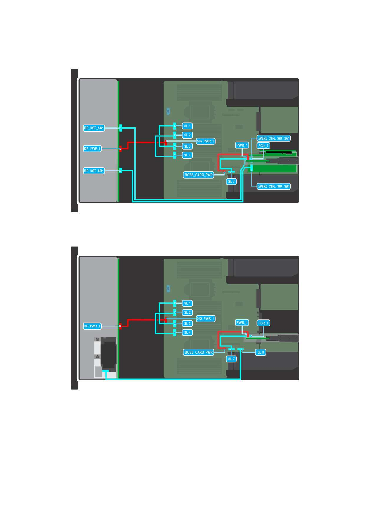
Page 29
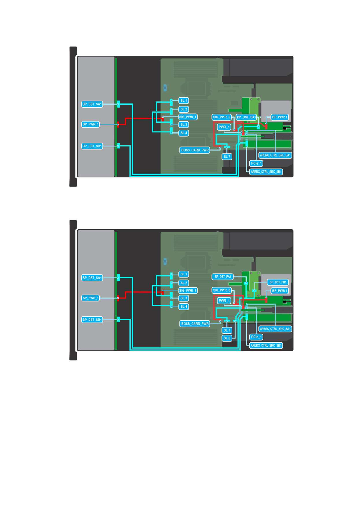
Figure 20. 12 x 3.5-inch with rear hard drives
Figure 21. 12 x 3.5-inch with NVMe
Installing and removing system components
29
Page 30
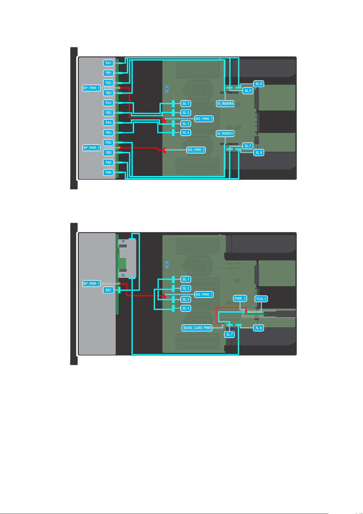
Figure 22. 24 x 2.5-inch with NVMe
Figure 23. 16 x 2.5-inch
30
Installing and removing system components
Page 31

Figure 24. 8 x 2.5-inch with NVMe
Figure 25. 8 x 2.5-inch with NVMe
Installing and removing system components
31
Page 32

Figure 26. 8 x 2.5-inch with NVMe
Figure 27. 16 x 2.5-inch with NVMe and GPUs
32
Installing and removing system components
Page 33

Figure 28. 8 x 2.5-inch with NVMe and GPUs
RIO card
Removing the Rear Input Output (RIO) card
Prerequisites
1. Follow the safety guidelines listed in the Safety instructions.
2. Follow the procedure listed in the Before working inside your system.
3. Remove the system board.
Steps
1. Using a Phillips #2 screwdriver, remove the screws that secure the RIO card to the system board.
2. Holding the edges, pull the RIO card to disconnect from the connector on the system board.
Installing and removing system components
33
Page 34

Figure 29. Removing the RIO card
Next steps
1. Replace the RIO card.
Installing the RIO card
Prerequisites
1. Follow the safety guidelines listed in the Safety instructions.
2. Follow the procedure listed in the Before working inside your system.
3. Remove the system board.
4. If required, remove the LOM card.
NOTE:
Upgrading the system board with the liquid cooling solution requires the LOM card to be replaced with the RIO
card.
Steps
1. Align the connectors and slots on RIO card with the connector and standoffs on the system board.
2. Press the RIO card until firmly seated on the system board connector.
3. Using a Phillips #2 screwdriver, secure the RIO card to the system board with the two screws.
34
Installing and removing system components
Page 35

Figure 30. Installing the RIO card
Next steps
1. Install the system board.
2. Follow the procedure listed in After working inside your system.
Optional front bezel
Removing the front bezel
The procedure to remove the front bezel with and without the LCD panel is the same.
Prerequisites
1. Follow the safety guidelines listed in the Safety instructions.
2. Keep the bezel key handy.
NOTE: The bezel key is part of the LCD bezel package.
Steps
1. Unlock the bezel.
2. Press the release button, and disengage the left end of the bezel.
3. Unhook the right end, and remove the bezel.
Installing and removing system components
35
Page 36

Figure 31. Removing the front bezel
Next steps
1. Replace the front bezel.
Installing the front bezel
The procedure to install the front bezel with and without the LCD panel is the same.
Prerequisites
1. Follow the safety guidelines listed in the Safety instructions.
2. Locate and remove the bezel key.
NOTE: The bezel key is part of the LCD bezel package.
Steps
1. Align and insert the tabs on the bezel into the slots on the system.
2. Press the bezel until the release button clicks in place.
3. Lock the bezel.
36
Installing and removing system components
Page 37

Figure 32. Installing the front bezel
System cover
Removing the system cover
Prerequisites
1. Follow the safety guidelines listed in the Safety instructions.
2. Power off the system, and any attached peripherals.
3. Disconnect the system from the electrical outlet and peripherals.
Steps
1. Using a 1/4-inch flat head or a Phillips #2 screwdriver rotate the lock counterclockwise to the unlock position.
2. Lift the release latch until the system cover slides back.
3. Lift the cover from the system.
Installing and removing system components
37
Page 38

Figure 33. Removing the system cover
Next steps
1. Replace the system cover.
Installing the system cover
Prerequisites
1. Follow the safety guidelines listed in the Safety instructions.
2. Follow the procedure listed in Before working inside your system.
3. Ensure that all internal cables are connected and routed properly, and no tools or extra parts are left inside the system.
Steps
1. Align the tabs on the system cover with the guide slots on the system and slide the system cover.
2. Close the system cover release latch.
3. Using a 1/4-inch flat head or Phillips #2 screwdriver, rotate the lock clockwise to the lock position.
38
Installing and removing system components
Page 39

Figure 34. Installing the system cover
Next steps
1. Follow the procedure listed in After working inside your system.
Drive backplane cover
Removing the drive backplane cover
Prerequisites
1. Follow the safety guidelines listed in the Safety instructions.
2. Follow the procedure listed in Before working inside your system.
Steps
1. Slide the backplane cover in the direction of the arrows marked on the drive backplane cover.
2. Lift the backplane cover from the system.
Installing and removing system components
39
Page 40

Figure 35. Removing the drive backplane cover
Next steps
1. Replace the drive backplane cover.
Installing the drive backplane cover
Prerequisites
1. Follow the safety guidelines listed in the Safety instructions.
Steps
1. Align the drive backplane cover with the guide slots on the system.
2. Slide the drive backplane cover to the front of the system until the drive backplane cover fits into place.
40
Installing and removing system components
Page 41

Figure 36. Installing the drive backplane cover
Next steps
1. Follow the procedure listed in After working inside your system.
Control panel
Removing the right control panel
Prerequisites
1. Follow the safety guidelines listed in the Safety instructions.
2. Follow the procedure listed in the Before working inside your system.
3. Remove the drive backplane cover.
4. If installed, remove the air shroud.
5. Remove the cooling fan assembly.
6. Remove the side wall bracket.
Steps
1. Using the Phillips #1 screwdriver, remove the screws that secure the right control panel and the right control panels cable
cover to the system and remove the cable cover away the system.
2. Disconnect the right control panel cable and the VGA cable from the connectors on the system board.
3. Holding the cable, slide the right control panel out of the system.
NOTE: Observe the routing of the cable as you remove the right control panel from the system.
NOTE: The numbers on the image do not depict the exact steps. The numbers are for representation of sequence.
Installing and removing system components 41
Page 42

Figure 37. Removing the right control panel
Next steps
1. Replace the right control panel.
Installing the right control panel
Prerequisites
1. Follow the safety guidelines listed in the Safety instructions.
2. Follow the procedure listed in Before working inside your system.
Steps
1. Align and slide the right control panel in the slot on the system.
2. Connect the right control panel cable and VGA cable to the connectors on the system board.
3. Route the right control panel cable through the side wall of the system. Align and slide the right control panel cable cover in
the slot on the system.
NOTE: Route the cable properly to prevent the cable from being pinched or crimped.
4. Using the Phillips #1 screwdriver, tighten the screws that secure the right control panel and the right control panel cable
cover to the system.
42
Installing and removing system components
Page 43

NOTE: The numbers on the image do not depict the exact steps. The numbers are for representation of sequence.
Figure 38. Installing the right control panel
Next steps
1. Install the side wall bracket.
2. Install the cooling fan assembly.
3. Install the drive backplane cover.
4. If removed, install the air shroud.
5. Follow the procedure listed in After working inside your system.
Removing the left control panel
Prerequisites
1. Follow the safety guidelines listed in the Safety instructions.
2. Follow the procedure listed in the Before working inside your system.
3. Remove the drive backplane cover.
4. If installed, remove the air shroud.
5. Remove the cooling fan assembly.
6. Remove the side wall bracket.
Installing and removing system components
43
Page 44

Steps
1. Disconnect the control panel cable from the connector on the system board.
2. Using the Phillips #1 screwdriver, remove the screws that secure the left control panel and the left control panels cable
cover to the system.
3. Hold the left control panel cable, and slide the left control panel out of the system.
NOTE: Observe the routing of the cable as you remove the right control panel from the system.
NOTE: The numbers on the image do not depict the exact steps. The numbers are for representation of sequence.
Figure 39. Removing the left control panel
Next steps
1. Replace the left control panel.
Installing the left control panel
Prerequisites
1. Follow the safety guidelines listed in the Safety instructions.
2. Follow the procedure listed in Before working inside your system.
Steps
1. Align and slide the left control panel in the slot on the system.
2. Connect the left control panel cable to the connector on the system board .
3. Route the left control panel cable through the side wall of the system. Align and slide the left control panel cable cover in the
slot on the system.
NOTE: Route the cable properly to prevent the cable from being pinched or crimped.
44 Installing and removing system components
Page 45

4. Using the Phillips #1 screwdriver, tighten the screws to secure the left control panel and the left control panel cable cover to
the system.
NOTE: The numbers on the image do not depict the exact steps. The numbers are for representation of sequence.
Figure 40. Installing the left control panel
Next steps
1. Install the side wall bracket.
2. Install the cooling fan assembly.
3. Install the drive backplane cover.
4. If removed, install the air shroud.
5. Follow the procedure listed in After working inside your system.
Installing and removing system components
45
Page 46

Air shroud
Removing the air shroud
Prerequisites
CAUTION: Never operate your system with the air shroud removed. The system may get overheated quickly,
resulting in shutdown of the system and loss of data.
1. Follow the safety guidelines listed in the Safety instructions.
2. Follow the procedure listed in Before working inside your system.
Steps
Hold the edges of the air shroud, and lift the air shroud out of the system.
Figure 41. Removing the air shroud
Next steps
1. Replace the air shroud.
Installing the air shroud
Prerequisites
1. Follow the safety guidelines listed in the Safety instructions.
2. Follow the procedure listed in Before working inside your system.
Steps
1. Align the slot on the air shroud with the standoff on the system.
46
Installing and removing system components
Page 47

2. Lower the air shroud into the system until it is firmly seated.
Figure 42. Installing the air shroud
Next steps
1. Follow the procedure listed in After working inside your system.
Removing the GPU air shroud
Prerequisites
CAUTION:
resulting in shutdown of the system and loss of data.
1. Follow the safety guidelines listed in the Safety instructions.
2. Follow the procedure listed in Before working inside your system.
Steps
Hold the edges of the GPU air shroud, and lift the air shroud out of the system.
Never operate your system with the air shroud removed. The system may get overheated quickly,
Installing and removing system components
47
Page 48

Figure 43. Removing the GPU air shroud
Next steps
1. Replace the air shroud.
Installing the GPU air shroud
Prerequisites
1. Follow the safety guidelines listed in the Safety instructions.
2. Follow the procedure listed in Before working inside your system.
Steps
1. Align the slot on the GPU air shroud with the standoff on the system.
2. Lower the GPU air shroud into the system until it is firmly seated.
48
Installing and removing system components
Page 49

Figure 44. Installing the GPU air shroud
Next steps
1. Follow the procedure listed in After working inside your system.
Removing the GPU air shroud top cover
Prerequisites
CAUTION:
resulting in shutdown of the system and loss of data.
1. Follow the safety guidelines listed in the Safety instructions.
2. Follow the procedure listed in Before working inside your system.
Steps
Press the blue tabs on either sides of the top cover, and lift the top cover out of the GPU air shroud.
Never operate your system with the air shroud removed. The system may get overheated quickly,
Installing and removing system components
49
Page 50

Figure 45. Removing the GPU air shroud top cover
Next steps
1. Replace the GPU air shroud top cover.
Installing the GPU air shroud top cover
Prerequisites
1. Follow the safety guidelines listed in the Safety instructions.
2. Follow the procedure listed in Before working inside your system.
Steps
1. Align the tabs on the top cover with the slots on the GPU air shroud.
2. Lower the top cover into the GPU air shroud until it is firmly seated.
50
Installing and removing system components
Page 51

Figure 46. Installing the GPU air shroud top cover
Next steps
1. Follow the procedure listed in After working inside your system.
Cooling fan
Removing the cooling fan cage assembly
Prerequisites
1. Follow the safety guidelines listed in the Safety instructions.
2. Follow the procedure listed in the Before working inside your system.
3. If installed, remove the air shroud.
Steps
1. Lift the blue release levers to unlock the cooling fan cage assembly from the system.
2. Hold the release levers, and lift the cooling fan cage assembly away from the system.
Installing and removing system components
51
Page 52

Figure 47. Removing the cooling fan cage assembly
Next steps
1. Install the cooling fan cage assembly.
Installing the cooling fan cage assembly
Prerequisites
1. Follow the safety guidelines listed in the Safety instructions.
CAUTION:
retention bracket before installing the cooling fan cage assembly. Incorrectly installed cables may get
damaged.
2. Follow the procedure listed in Before working inside your system.
3. If installed, remove the air shroud.
Steps
1. Align the guide rails on the cooling fan cage assembly with the standoffs on the system.
2. Lower the cooling fan cage assembly into the system until the cooling fan cage connectors engage with the connectors on
the system board.
3. Press the release levers to lock the cooling fan cage assembly into the system.
Ensure that the cables inside the system are correctly installed and retained by the cable
52
Installing and removing system components
Page 53

Figure 48. Installing the cooling fan cage assembly
Next steps
1. If removed, install the air shroud.
2. Follow the procedure listed in After working inside your system.
Removing a cooling fan
Prerequisites
1. Follow the safety guidelines listed in the Safety instructions.
2. Follow the procedure listed in Before working inside your system.
3. If installed, remove the air shroud.
Steps
Press the orange release tab and lift the cooling fan to disconnect the fan from the connector on the system board.
NOTE: The procedure to remove standard, high-performance (silver grade), or high-performance (gold grade) fan is same.
WARNING: Ensure not to tilt or rotate the cooling fan while removing from the system.
Installing and removing system components 53
Page 54

Figure 49. Removing a cooling fan
Next steps
1. Replace a cooling fan.
Installing a cooling fan
Prerequisites
1. Follow the safety guidelines listed in the Safety instructions.
2. Follow the procedure listed in Before working inside your system.
Steps
Align and slide the cooling fan into the cooling fan assembly until the fan clicks into place.
NOTE: The procedure to install standard, high-performance (silver grade), or high-performance (gold grade) fan is same.
54 Installing and removing system components
Page 55

Figure 50. Installing a cooling fan
Next steps
1. If removed, install the air shroud.
2. Follow the procedure listed in After working inside your system.
Side wall brackets
Removing the side wall bracket
Prerequisites
1. Follow the safety guidelines listed in the Safety instructions.
2. Follow the procedure listed in the Before working inside your system.
3. If installed, remove the front bezel.
4. Remove the backplane cover.
5. If installed, remove the air shroud.
6. Remove the cooling fan assembly.
NOTE:
Ensure that you note the routing of the cables as you remove them from the system board. Route the cable
properly when you replace it to prevent the cable from being pinched or crimped.
Steps
1. Press the tab to release the side wall bracket cover.
NOTE: Unroute the cables to release them from the side wall bracket.
2. Release the bracket from the chassis, and lift it away from the system.
Installing and removing system components
55
Page 56

Figure 51. Removing the side wall bracket
Next steps
1. Replace the side wall bracket.
Installing the side wall bracket
Prerequisites
1. Follow the safety guidelines listed in the Safety instructions.
2. Follow the procedure listed in the Before working inside your system.
3. If installed, remove the front bezel.
4. Remove the backplane cover.
5. If installed, remove the air shroud.
NOTE:
Ensure that you note the routing of the cables as you remove them from the system board. Route the cable
properly when you replace it to prevent the cable from being pinched or crimped.
Steps
1. Align the side wall bracket with the tabs on the chassis.
2. Press the side wall bracket with your thumbs until the bracket firmly clicks into place.
NOTE: Route the cables through the side wall bracket.
3. Close the side wall bracket cover with your thumbs until the cover firmly clicks into place.
56
Installing and removing system components
Page 57

Figure 52. Installing the side wall bracket
Next steps
1. Replace the cooling fan assembly.
2. If removed, install the air shroud.
3. Install the backplane cover.
4. If installed, install the front bezel.
5. Follow the procedure listed in the After working inside your system.
Drives
Removing a drive blank
Prerequisites
1. Follow the safety guidelines listed in the Safety instructions.
2. If installed, remove the front bezel.
CAUTION: To maintain proper system cooling, drive blanks must be installed in all empty drive slots.
Steps
Press the release button, and slide the drive blank out of the drive slot.
Installing and removing system components
57
Page 58

Figure 53. Removing a drive blank
Next steps
1. Replace the drive blank.
Installing a drive blank
Prerequisites
1. Follow the safety guidelines listed in the Safety instructions.
2. If installed, remove the front bezel.
Steps
Insert the drive blank into the drive slot until the release button clicks into place.
Figure 54. Installing a drive blank
Next steps
1. If removed, install the front bezel.
Removing the drive carrier
Prerequisites
1. Follow the safety guidelines listed in the Safety instructions.
2. If installed, remove the front bezel.
3. Using the management software, prepare the drive for removal.
If the drive is online, the green activity or fault indicator blinks while the drive is powering off. When the drive indicators are
off, the drive is ready for removal. For more information, see the documentation for the storage controller.
58
Installing and removing system components
Page 59

CAUTION: Before attempting to remove or install a drive while the system is running, see the documentation
for the storage controller card to ensure that the host adapter is configured correctly to support drive
removal and insertion.
CAUTION: To prevent data loss, ensure that your operating system supports drive installation. For more
information about the drives installation or uninstallation requirements, see the operating system's user
guide.
Steps
1. Press the release button to open the drive carrier release handle.
2. Holding the drive carrier release handle, slide the drive carrier out of the drive slot.
Figure 55. Removing a drive carrier
Next steps
1. Install a drive carrier or drive blank.
Installing the drive carrier
Prerequisites
CAUTION:
storage controller card to ensure that the host adapter is configured correctly to support drive removal and
insertion.
CAUTION: Combining SAS and SATA drives in the same RAID volume is not supported.
CAUTION: When installing a drive, ensure that the adjacent drives are fully installed. Inserting a drive carrier
and attempting to lock its handle next to a partially installed carrier can damage the partially installed carrier's
shield spring and make it unusable.
CAUTION: To prevent data loss, ensure that your operating system supports hot-swap drive installation. See the
documentation supplied with your operating system.
NOTE: When a replacement hot swappable drive is installed while the system is powered on, the drive automatically begins
to rebuild. Ensure that the replacement drive is blank. Any data on the replacement drive is immediately lost once the drive
is installed.
Before removing or installing a drive while the system is running, see the documentation for the
Installing and removing system components 59
Page 60

NOTE: Ensure that the drive carrier's release handle is in the open position before inserting the carrier into the slot.
1. Follow the safety guidelines listed in the Safety instructions.
2. If installed, remove the front bezel.
3. Remove the drive carrier or remove the drive blank when you want to assemble the drives in to the system.
Steps
1. Slide the drive carrier into the drive slot.
2. Close the drive carrier release handle to lock the drive in place.
Figure 56. Installing a drive carrier
Next steps
If removed, install the front bezel.
Removing the drive from the drive carrier
Prerequisites
1. Follow the safety guidelines listed in the Safety instructions.
2. If installed, remove the front bezel.
Steps
1. Using a Phillips #1 screwdriver, remove the screws from the slide rails on the drive carrier.
If the hard drive or SSD carrier has Torx screw, use Torx 6 (for 2.5-inch drive) or Torx 8 (for 3.5-inch drive)
NOTE:
screwdriver to remove the drive.
60 Installing and removing system components
Page 61

2. Lift the drive out of the drive carrier.
Figure 57. Removing the drive from the drive carrier
Next steps
Install the drive into the drive carrier.
Installing the drive into the drive carrier
Prerequisites
1. Follow the safety guidelines listed in the Safety instructions.
2. If installed, remove the front bezel.
3. Remove the drive blank.
Steps
1. Insert the drive into the drive carrier with the drive connector facing towards the rear of the carrier.
2. Align the screw holes on the drive with the screws holes on the drive carrier.
3. Using a Phillips #1 screwdriver, secure the drive to the drive carrier with the screws.
NOTE: When installing a drive into the drive carrier, ensure that the screws are torqued to 4 lbf-in.
NOTE: If the hard drive or SSD carrier has Torx screw, use Torx 6 (for 2.5-inch drive) or Torx 8 (for 3.5-inch drive)
screwdriver to install the drive.
Installing and removing system components 61
Page 62

Figure 58. Installing a drive into the drive carrier
Next steps
1. Install the drive carrier.
2. If removed, install the front bezel.
Drive backplane
Drive backplane
Depending on your system configuration, the drive backplanes supported are listed here:
Table 11. Supported backplane options
System Supported hard drives options
3.5-inch (x8) SAS, SATA backplane
3.5-inch (x12) SAS or SATA backplane
PowerEdge R7525
62 Installing and removing system components
2.5-inch (x8) SAS, SATA or NVMe backplane
2.5-inch (x16) SAS or SATA backplane
2.5-inch (x24) NVMe backplane
Page 63

Figure 59. 8 x 2.5-inch drive backplane
1. BP_PWR_CTRL 2. BP_DST_SA1 (PERC to backplane)
3. DST_PA1 (PCIe/NVMe connector) 4. DST_PB1 (PCIe/NVMe connector)
5. DST_PA2 (PCIe/NVMe connector) 6. BP_PWR_1 (backplane power and signal cable to system
board)
7. DST_PB2 (PCIe/NVMe connector)
Figure 60. 8 x 3.5-inch drive backplane
1. BP_PWR_1 (backplane power and signal cable to system board)
Figure 61. 12x 3.5-inch drive backplane
1. BP_DST_SB1
2. BP_PWR_1 (backplane power and signal cable to system board)
3. BP_DST_SA1
Installing and removing system components
63
Page 64

Figure 62. 16 x 2.5-inch drive backplane
1. BP_DST_SB1 (backplane to front PERC) 2. BP_PWR_1 (backplane power and signal cable to system
board)
3. BP_PWR_CTRL (front PERC power and control signal) 4. BP_DST_SA1 (backplane to front PERC)
Figure 63. 24 x 2.5-inch drive backplane
DST_PB6 (PCIe/NVMe connector) 2. DST_PA6 (PCIe/NVMe connector)
1.
3. DST_PB5 (PCIe/NVMe connector) 4. DST_PWR_2 (backplane power and signal cable to system
board)
5. DST_PA5 (PCIe/NVMe connector) 6. DST_PB4 (PCIe/NVMe connector)
7. DST_PA4 (PCIe/NVMe connector) 8. DST_PB3 (PCIe/NVMe connector)
9. DST_PA3 (PCIe/NVMe connector) 10. DST_PB2 (PCIe/NVMe connector)
11. DST_PWR_1 (backplane power and signal cable to system
board)
13. DST_PB1 (PCIe/NVMe connector) 14. DST_PA1 (PCIe/NVMe connector)
12. DST_PA2 (PCIe/NVMe connector)
Removing the drive backplane
Prerequisites
CAUTION:
the backplane.
CAUTION: Note the number of each drive and temporarily label them before you remove the drive so that you
can reinstall them in the same location.
NOTE: The procedure to remove the backplane is similar for all backplane configurations.
1. Follow the safety guidelines listed in the Safety instructions.
2. Follow the procedure listed in the Before working inside your system.
3. Remove the backplane cover.
4. If installed,remove the air shroud.
5. Remove all the drives.
6. Remove the cooling fan cage assembly.
7. Disconnect the drive backplane cables from the connector on the system board.
8. Disconnect the drive backplane cables from the connector on the backplane.
64
To prevent damage to the drives and backplane, remove the drives from the system before removing
Installing and removing system components
Page 65

Steps
1. Press the blue release tabs to disengage the drive backplane from the hooks on the system.
2. Lift and pull the drive backplane out of the system.
NOTE: To avoid damaging the backplane, ensure that you move the control panel cables from the cable routing clips
before removing the backplane.
Figure 64. Removing the drive backplane
Next steps
1. Replace the drive backplane.
Installing the drive backplane
Prerequisites
1. Follow the safety guidelines listed in the Safety instructions.
2. Follow the procedure listed in the Before working inside your system.
3. Remove the backplane cover.
4. If installed,remove the air shroud.
5. Remove all the drives.
6. Remove the cooling fan cage assembly.
To avoid damaging the backplane, ensure to move the control panel cables from the cable routing clips before
NOTE:
removing the backplane.
NOTE: Route the cable properly when you replace it to prevent the cable from being pinched or crimped.
Steps
1. Use the guides on the system as guides to align the slots on the backplane.
2. Insert the backplane into the guides and lower the backplane until the blue release tabs clicks into place.
Installing and removing system components
65
Page 66

3. Route the cables properly through the cable guide and connect the cables to the connector on the system board.
Figure 65. Installing the drive backplane
Next steps
1. Install the cooling fan cage assembly.
2. Install all the drives.
3. If removed, install the air shroud.
4. Install the drive backplane cover.
5. Connect the drive backplane cables to the connector on the system board.
6. Connect the drive backplane cables to the connector on the backplane.
7. Follow the procedure listed in After working inside your system.
Rear drive cage
Removing the rear drive cage
Prerequisites
1. Follow the safety guidelines listed in the Safety instructions.
2. Follow the procedure listed in the Before working inside your system.
3. Remove all the drives.
4. Disconnect all the cables from the rear drive cage.
5. If installed, remove the expansion card riser.
Steps
1. Loosen the captive screws that secure the rear drive cage to the system.
2. Push the guide hole tab to release the rear drive cage from the system and lift the rear drive cage away from the system.
66
Installing and removing system components
Page 67

Figure 66. Removing the rear drive cage
Next steps
1. Replace the rear drive cage.
Installing the rear drive cage
Prerequisites
1. Follow the safety guidelines listed in the Safety instructions.
2. Follow the procedure listed in Before working inside your system.
Steps
1. Align the guide and slot on the rear drive module with the slot and guide on the system.
2. Insert the rear drive module on top of the Riser 2a.
3. Tighten the captive screws to secure the rear drive cage to the system.
Installing and removing system components
67
Page 68

Figure 67. Installing the rear drive cage
Next steps
1. Replace the expansion card riser, if needed.
2. Connect all the cables to the rear drive cage.
3. Install all the drives.
4. Follow the procedure listed in After working inside your system.
Front PERC module
Removing the front mounting front PERC module
Prerequisites
1. Follow the safety guidelines listed in the Safety instructions.
2. Follow the procedure listed in the Before working inside your system.
3. remove the backplane cover.
4. If installed, remove the air shroud.
5. Disconnect all the cables, observe the cable routing.
Steps
1. Using a Phillips #2 screwdriver, loosen the captive screws on the front PERC module.
2. Slide and pull the front PERC module to disengage from the connector on the drive backplane.
68
Installing and removing system components
Page 69

Figure 68. Removing the front mounting front PERC module
Next steps
1. Replace the front mounting front PERC module.
Installing the front mounting front PERC module
Prerequisites
1. Follow the safety guidelines listed in the Safety instructions.
2. Follow the procedure listed in Before working inside your system.
3. Remove the backplane cover.
4. If installed, remove the air shroud.
5. Route the cable properly to prevent the cable from being pinched or crimped.
Steps
1. Align the front PERC module at an angle until the tray touches the slot in the system.
2. Slide and press the front PERC module connector with the connector on the drive backplane until firmly seated.
3. Using a Phillips #2 screwdriver, tighten the captive screws on the front PERC module.
NOTE: The numbers on the image do not depict the exact steps. The numbers are for representation of sequence.
Installing and removing system components 69
Page 70

Figure 69. Installing the front mounting front PERC module
Next steps
1. Reconnect all the required cables.
2. If removed, install the air shroud.
3. Install the drive backplane cover.
4. Follow the procedure listed in After working inside your system.
Removing the rear mounting front PERC module
Prerequisites
1. Follow the safety guidelines listed in the Safety instructions.
2. Follow the procedure listed in the Before working inside your system.
3. Remove the backplane cover.
4. If installed, remove the air shroud.
5. Remove the drive backplane.
6. Disconnect all the cables, observe the cable routing.
Steps
1. Using a Phillips #2 screwdriver, loosen the captive screws on the front PERC module.
2. Slide the front PERC module to disengage from the connector on the drive backplane.
70
Installing and removing system components
Page 71

Figure 70. Removing the rear mounting front PERC module
Next steps
1. Replace the rear mounting front PERC module.
Installing the rear mounting front PERC module
Prerequisites
1. Follow the safety guidelines listed in the Safety instructions.
2. Follow the procedure listed in Before working inside your system.
3. Remove the backplane cover.
4. If installed, remove the air shroud.
5. Remove the drive backplane.
6. Route the cable properly to prevent the cable from being pinched or crimped.
Steps
1. Align the connectors and guide slots on the front PERC module with the connectors and guide pins on the drive backplane.
2. Slide the front PERC module until the module is connected to the drive backplane.
3. Using a Phillips #2 screwdriver, tighten the captive screws on the front PERC module.
NOTE: The numbers on the image do not depict the exact steps. The numbers are for representation of sequence.
Installing and removing system components 71
Page 72

Figure 71. Installing the rear mounting front PERC module
Next steps
1. Install the drive backplane.
2. If removed, install the air shroud.
3. Install the drive backplane cover.
4. Follow the procedure listed in After working inside your system.
System memory
System memory guidelines
The PowerEdge R7525 system supports DDR4 registered DIMMs (RDIMMs) and Load Reduced DIMM (LRDIMMs). System
memory holds the instructions that are started by the processor.
Your system memory is organized into eight channels per processor (two memory sockets per channel),16 memory sockets per
processor and 32 memory sockets per system.
72
Installing and removing system components
Page 73

Figure 72. Memory channels
Memory channels are organized as follows:
Table 12. Memory channels
Processor ChannelAChannelBChannel C Channel D Channel E Channel F Channel G Channel H
Processor 1 Slots A6
and A12
Processor2Slots B6
and B12
Slots A5
and A11
Slots B5
and B11
Slots A2
and A10
Slots B2
and B10
Slots A1 andA9Slots A8 and
A16
Slots B1 andB9Slots B8 and
B16
Table 13. Supported memory matrix
DIMM type Rank Capacity DIMM rated
RDIMM 1 R 8 GB DDR4 (1.2 V), 3200
2 R 16 GB, 32 GB, 64GBDDR4 (1.2 V), 3200
LRDIMM 8 R 128 GB DDR4 (1.2 V), 2666
8R 128 GB DDR4 (1.2 V), 3200
voltage and
speed
MT/s
MT/s
MT/s
MT/s
Slots A7
and A15
Slots B7
and B15
Operating Speed
1 DIMM per
channel (DPC)
3200 MT/s 2933 MT/s
3200 MT/s 2933 MT/s
2666 MT/s 2666 MT/s
3200 MT/s 2933 MT/s
Slots A4 and
A14
Slots B4 and
B14
Slots A3 and
A13
Slots B3 and
B13
2 DIMMs per
channel (DPC)
Installing and removing system components 73
Page 74

General memory module installation guidelines
To ensure optimal performance of your system, observe the following general guidelines when configuring your system memory.
If your system's memory configurations fail to observe these guidelines, your system might not boot, stop responding during
memory configuration, or operate with reduced memory. This section provides information on the memory population rules and
about the non-uniform memory access (NUMA) for single or dual processor system.
The memory bus may operate at speeds of 3200 MT/s, 2933 MT/s, or 2666 MT/s depending on the following factors:
● System profile selected (for example, Performance Optimized, or Custom [can be run at high speed or lower])
● Maximum supported DIMM speed of the processors
Maximum supported speed of the DIMMs
●
NOTE: MT/s indicates DIMM speed in MegaTransfers per second.
The system supports Flexible Memory Configuration, enabling the system to be configured and run in any valid chipset
architectural configuration. The following are the recommended guidelines for installing memory modules:
● All DIMMs must be DDR4.
● Mixing of memory module capacities in a system is not supported.
● If memory modules with different speeds are installed, they operate at the speed of the slowest installed memory module(s).
● Populate memory module sockets only if a processor is installed.
○ For single-processor systems, sockets A1 to A16 are available.
○ For dual-processor systems, sockets A1 to A16 and sockets B1 to B16 are available.
○ In Optimizer Mode, the DRAM controllers operate independently in the 64-bit mode and provide optimized memory
performance.
Table 14. Memory population rules
Processor Configuration Memory population Memory population
Single processor Optimizer (Independent
channel) population order
Dual processor (Start
with processor1. Processor
1 and processor 2
population should match)
● Populate all the sockets with white release tabs first, followed by the black release tabs.
● In a dual-processor configuration, the memory configuration for each processor must be identical. For example, if you
populate socket A1 for processor 1, then populate socket B1 for processor 2, and so on.
● Unbalanced or odd memory configuration results in a performance loss and system may not identify the memory modules
being installed, so always populate memory channels identically with equal DIMMs for best performance.
● Minimum recommended configuration is to populate four equal memory modules per processor. AMD recommends limiting
processors in that system to 32 cores or less.
● Populate eight equal memory modules per processor (one DIMM per channel) at a time to maximize performance.
Equal memory modules refer to DIMMs with identical electrical specification and capacity that may be from
NOTE:
different vendors.
Memory interleaving with Non-uniform memory access (NUMA)
Non-uniform memory access (NUMA) is a memory design used in multi-processing, where the memory access time depends on
the memory location relative to the processor. In NUMA, a processor can access its own local memory faster than the non-local
memory.
NUMA nodes per socket (NPS) is a new feature added that allows you to configure the memory NUMA domains per socket.
The configuration can consist of one whole domain (NPS1), two domains (NPS2), or four domains (NPS4). In the case of a
two-socket platform, an additional NPS profile is available to have whole system memory to be mapped as single NUMA domain
(NPS0). For more information on the memory interleaving for NPSx, see the Memory interleaving population rules section in this
topic.
BIOS implementation for NPSx
● The BIOS Setup menu presents the applicable NPSx options based on the underlying model number. A change to the current
NPSx is communicated to pre-BIOS firmware to take effect on the next boot. The default NPS setting is 1.
Optimizer (Independent
channel) population order
A{1}, A{2}, A{3}, A{4}, A{5},
A{6}, A{7}, A{8}, A{9}, A{10},
A{11}, A{12}, A{13}, A{14}, A{15},
A{16}
A{1}, B{1}, A{2}, B{2}, A{3}, B{3},
A{4}, B{4}, A{5}, B{5}, A{6},
B{6}, A{7}, B{7} A{8}, B{8}
information
Odd amount of DIMMs per
processor allowed.
Odd amount of DIMMs
per processor is allowed.
DIMMs must be populated
identically per processor.
74
Installing and removing system components
Page 75

● During boot, if the selected NPSx option is not allowed for the model number (for example, if the processor model number
changes between reboot), system will halt at the end of POST with UEFI0388 message displayed. On the next reboot, the
system will fall back to NPS1 default setting.
● During boot, if the preferred interleaving for the current NPSx is not possible due to memory configuration (for example, the
memory population is inconsistent with the preferred interleaving), BIOS shows a warning message UEFI0391.
NOTE: System is functional when UEFI0391 message is displayed. However, the system may not be configured for
optimal performance.
NPS system optimization
Optimal system configuration is dependent on the processor model, memory configuration, and NPS settings. Match the
memory configuration with the NPS settings available for the processor.
Table 15. Supported NPS modes by Processors
Model Number NPS modes supported
7742 4, 2, 1, 0
7702 4, 2, 1, 0
7662 4, 2, 1, 0
7642 4, 2, 1, 0
7552 2, 1, 0
7542 4, 2, 1, 0
7532 4, 2, 1, 0
7502 4, 2, 1, 0
7452 4, 2, 1, 0
7402 4, 2, 1, 0
7352 4, 2, 1, 0
7302 4, 2, 1, 0
7282 1, 0
7272 1, 0
7262 4, 2, 1, 0
7252 1, 0
7F72 2, 1, 0
7F52 4, 2, 1, 0
7F32 4, 2, 1, 0
7H12 4, 2, 1, 0
7713 4, 2, 1, 0
7543 4, 2, 1, 0
7763 4, 2, 1, 0
Table 16. Optimal NPS configuration
Number of
DIMMs per
processor
1 X
2 X
3 X
4 X
0 1 2 4
NPS
Installing and removing system components 75
Page 76

Table 16. Optimal NPS configuration
Number of
DIMMs per
processor
5 X
6 X
7 X
8 X X
9 X
10 X
11 X
12 X
13 X
14 X
15 X
16 X X
● Recommended NPS setting is marked by X that indicate optimal performance.
● NPS0 is only available for dual processor systems and is the preferred setting.
● The NPS setting that are blank are functional. However, indicate non-optimal performance.
● BIOS default NPS setting is 1.
● UEFI0391 message may be displayed during boot if DIMMs are configured in the blank spaces of the table.
● If the processor does not support the desired NPS setting for a given number of DIMMs, then use default setting (NPS1)
and the UEFI0391 message is displayed.
Memory interleaving population rules
● NPS4: Two channel interleaving
○ This interleaves channel [A and B], [C and D], etc.
○ Each channel within the pair requires at least one equal memory modules populated.
○ Works with three memory modules per channel pair, non-symmetrical module is stacked on top (odd configurations).
○ Any memory channel where one of the two channels is not populated is not interleaved.
○ There is no alternate, as all configurations can be mapped into this mode.
● NPS2: Four channel interleaving
○ This interleaves the four channels on the left or right half of a processor which are channels [A, B, C, D] and [E, F, G, H].
○ All four channels require equal memory modules populated.
○ Each half or interleave set may have different total memory capacity with respect to each other.
● NPS1: Eight channel interleaving
○ This interleaves all channels in a processor [A, B, C, D, E, F, G, H].
○ All channels in a processor require equal memory modules populated.
○ Single processor system creates a single NUMA node for the system.
An exception is allowed when system has 4-channels populated [C, D, G, H] with equal memory allowing the
NOTE:
system to enter NPS1 mode even though all the 8 channels are not populated.
● NPS0: Sixteen channel interleaving (dual processor)
○ This interleaves all 16 channels in a dual processor system.
○ All channels in a system require equal memory modules populated.
○ Dual processor systems create a single NUMA node for the system.
0 1 2 4
NPS
Removing a memory module
Prerequisites
1. Follow the safety guidelines listed in the Safety instructions.
76
Installing and removing system components
Page 77

2. Follow the procedure listed in the Before working inside your system.
3. If installed, remove the air shroud.
WARNING: The memory modules are hot to touch for some time after the system has been powered off. Allow
the memory modules to cool before handling them. Handle the memory modules by the card edges and avoid
touching the components or metallic contacts on the memory module.
Steps
1. Locate the appropriate memory module socket.
2. To release the memory module from the socket, simultaneously press the ejectors on both ends of the memory module
socket.
CAUTION: Handle each memory module only by the card edges, ensuring not to touch the middle of the
memory module or metallic contacts.
3. Lift the memory module away from the system.
Figure 73. Removing a memory module
Next steps
1. Replace the memory module.
Installing a memory module
Prerequisites
1. Follow the safety guidelines listed in the Safety instructions.
2. Follow the procedure listed in Before working inside your system.
3. If installed, remove the air shroud.
WARNING:
the memory modules to cool before handling them. Handle the memory modules by the card edges and avoid
touching the components or metallic contacts on the memory module.
Steps
1. Locate the appropriate memory module socket.
CAUTION:
memory module or metallic contacts.
The memory modules are hot to touch for some time after the system has been powered down. Allow
Handle each memory module only by the card edges, ensuring not to touch the middle of the
2. If a memory module is installed in the socket, remove it.
Installing and removing system components
77
Page 78

3. Align the edge connector of the memory module with the alignment key of the memory module socket, and insert the
memory module in the socket.
NOTE: Ensure the memory socket ejectors are fully open.
NOTE: The memory module socket has an alignment key that enables you to install the memory module in the socket in
only one orientation.
CAUTION: Do not apply pressure at the center of the memory module; apply pressure at both ends of the
memory module evenly.
CAUTION: To prevent damage to the memory module or the memory module socket during installation, do
not bend or flex the memory module; insert both ends of the memory module simultaneously.
4. Press the memory module with your thumbs until the ejectors firmly click into place. When the memory module is properly
seated in the socket, the levers on the memory module socket align with the levers on the other sockets that have memory
modules installed.
Figure 74. Installing a memory module
Next steps
1. If removed, install the air shroud.
2. Follow the procedure listed in After working inside your system.
3. To verify if the memory module has been installed properly, press F2 and navigate to System Setup Main Menu > System
BIOS > Memory Settings. In the Memory Settings screen, the System Memory Size must reflect the updated capacity of
the installed memory.
4. If the System Memory Size is incorrect, one or more of the memory modules may not be installed properly. Ensure that the
memory modules are firmly seated in their sockets.
5. Run the system memory test in system diagnostics.
78
Installing and removing system components
Page 79

Processor and heat sink
Removing a heat sink
Prerequisites
1. Follow the safety guidelines listed in the Safety instructions.
2. Follow the procedure listed in the Before working inside your system.
3. If installed, remove the air shroud.
WARNING: The heat sink and processor are too hot to touch for some time after the system has been powered
off. Allow the heat sink and processor to cool down before handling them.
NOTE: The procedure to uninstall standard and L-type heat sink is similar.
Steps
1. Using a Torx #T20 screwdriver, loosen the captive screws in the order that is mentioned on the heat sink:
a. Partially loosen the captive screws 1 and 2 (approximately 3 turns).
b. Partially loosen the captive screws 3 and 4 (approximately 3 turns).
c. Loosen the captive screws 1 and 2 completely.
d. Loosen the captive screws 3 and 4 completely.
NOTE: The captive screw numbers are marked on the heat sink.
2. Lift the heat sink from the system.
Figure 75. Removing a heat sink
Next steps
1. If you are uninstalling a faulty heat sink, replace the heat sink, else remove the processor.
Installing and removing system components
79
Page 80

Removing the liquid cooling heat sink modules
Prerequisites
1. Follow the safety guidelines listed in the Safety instructions.
2. Follow the procedure listed in the Before working inside your system.
3. If installed, remove the air shroud.
WARNING: The liquid cooling heat sink modules and processor are too hot to touch for some time after the
system has been powered off. Allow the heat sink and processor to cool down before handling them.
Steps
1. Using a Phillips #1 screw driver, loosen the captive screw on the liquid cooling ring holder.
2. Lift up the liquid cooling ring holder to loosen the liquid cooling tubes.
3. Disconnect the liquid cooling detection cable from the Rio card connector.
NOTE: The numbers on the image do not depict the exact steps. The numbers are for representation of sequence.
4. Remove the liquid cooling tubes end point from the rear exit of the I/O function panel.
5. Slightly lift up the liquid cooling tubes surrounding the DIMM slots.
6. Using a Torx #T20 screwdriver, loosen the captive screws in the order that is mentioned on the liquid cooling heat sink
modules:
a. Partially loosen the captive screws 1 and 2 (approximately 3 turns).
b. Partially loosen the captive screws 3 and 4 (approximately 3 turns).
c. Loosen the captive screws 1 and 2 completely.
d. Loosen the captive screws 3 and 4 completely.
NOTE: The captive screw numbers are marked on the liquid cooling heat sink modules.
7. Lift the heat sink from the system.
80
Installing and removing system components
Page 81

Figure 76. Removing the liquid cooling heat sink modules
Next steps
1. If you are uninstalling a faulty heat sink, replace the liquid cooling heat sink modules, else remove the processor.
Removing the processor
Prerequisites
WARNING:
heat sink to cool before removing it.
1. Follow the safety guidelines listed in the Safety instructions.
2. Follow the procedure listed in the Before working inside your system.
3. Remove the heat sink.
CAUTION:
of powering on the system after the processor or system board replacement which is expected. To fix, go to set
up option to configure the system settings.
Steps
1. Using a Torx #T20 screwdriver, loosen the screws to release the force plate. The sequence to loosen the screws is 3, 2, and
1.
The heat sink may be hot to touch for some time after the system has been powered off. Allow the
You may find the CMOS battery loss or CMOS checksum error is displayed during the first instance
NOTE: The screw numbers are marked on the force plate.
Installing and removing system components 81
Page 82

Figure 77. Removing screws on the force plate
2. Release the processor socket rail frame by lifting the blue latches.
Figure 78. Lifting the rail frame
3. Holding the blue tab on the processor tray, slide the tray out of the rail frame.
82
Installing and removing system components
Page 83

Figure 79. Removing the processor tray
Next steps
1. Replace the processor.
Installing the processor
Prerequisites
1. Follow the safety guidelines listed in the Safety instructions.
2. Follow the procedure listed in Before working inside your system.
3. Remove the heat sink.
Steps
1. Holding the blue tab on the processor tray, slide the tray into the processor socket rail frame until firmly seated.
Installing and removing system components
83
Page 84

Figure 80. Placing the processor tray into the rail frame
2. Push the rail frame down until the blue latches lock into place.
Figure 81. Closing the rail frame
3. Secure the force plate to the processor socket base by tightening the screws in the sequence 1, 2, and 3. When all three
screws are fully threaded, the socket is then actuated. The three screws are tightened to a torque value of 12.0 ± 1.2 lbf-in.
NOTE: The screw numbers are marked on the force plate.
NOTE: Press the force plate while tightening the screws to avoid tilting of the processor cover out of the processor
socket.
84 Installing and removing system components
Page 85

Figure 82. Securing the force plate
Next steps
1. Install the heat sink.
2. Follow the procedure listed in After working inside your system.
Installing the heat sink
Prerequisites
Never uninstall the heat sink from a processor unless you intend to replace the processor or system board. The heat sink is
necessary to maintain proper thermal conditions.
1. Follow the safety guidelines listed in the Safety instructions.
2. Follow the procedure listed in the Before working inside your system.
3. If installed, remove the air shroud.
4. If installed, remove the processor dust cover.
NOTE: The procedure to install standard and L-type heat sink is similar.
Steps
1. If you are using an existing heat sink, remove the thermal grease on the heat sink by using a clean lint-free cloth.
For a new heat sink, the thermal paste is preapplied to the heat sink. Remove the protective cover, and install
NOTE:
the heat sink.
2. Use the thermal grease syringe included with your processor kit to apply the grease in a thin spiral on the top of the
processor.
Installing and removing system components
85
Page 86

Figure 83. Applying thermal grease
CAUTION:
contaminating the processor socket.
NOTE: The thermal grease syringe is intended for single use only. Dispose of the syringe after you use it.
3. Align the screws on the heat sink with the standoff screws on the system board.
NOTE: The A1 extrusion on the L-type heat sink should face towards the system side.
4. Using a Torx #T20 screwdriver, tighten the captive screws in the order that is mentioned below:
NOTE: The captive screw numbers are marked on the heat sink and are tightened to a torque value of 12.0 ± 1.2 lbf-in.
a. Partially tighten the captive screws 1 and 2 (approximately 3 turns).
b. Partially tighten the captive screws 3 and 4 (approximately 3 turns).
c. Tighten the captive screws 1 and 2 completely.
d. Tighten the captive screws 3 and 4 completely.
Applying too much thermal grease can result in excess grease coming in contact with and
86
Installing and removing system components
Page 87

Figure 84. Installing the heat sink
Next steps
1. If removed, install the air shroud.
2. Follow the procedure listed in the After working inside your system.
Installing the liquid cooling heat sink
Prerequisites
Never uninstall the heat sink from a processor unless you intend to replace the processor or system board. The heat sink is
necessary to maintain proper thermal conditions.
1. Follow the safety guidelines listed in the Safety instructions.
2. Follow the procedure listed in the Before working inside your system.
3. If installed, remove the air shroud.
4. If installed, remove the processor dust cover.
5. For new heat sinks, refer to Installing the heat sink step 1 and 2 for applying the thermal grease.
Steps
1. Align the screws on the liquid cooling heat sink with the standoff screws on the system board. Ensure that the liquid cooling
tubes and liquid detection cable are placed towards the rear of the chassis. Using a Torx #T20 screwdriver, tighten the
captive screws in the order that is mentioned below:
NOTE: The captive screw numbers are marked on the heat sink and are tightened to a torque value of 12.0 ± 1.2 lbf-in.
a. Partially tighten the captive screws 1 and 2 (approximately 3 turns).
b. Partially tighten the captive screws 3 and 4 (approximately 3 turns).
c. Tighten the captive screws 1 and 2 completely.
d. Tighten the captive screws 3 and 4 completely.
2. Ensure that the liquid cooling tubes leading towards the front of the chassis are placed between the DIMM slots and the
J_SL connectors. And the tubes leading towards the rear of the chassis are placed in between the DIMM slots and the relay
components.
Liquid detection cable must be placed underneath the cooling tubes to ensure it does not interfere with the PCIe
NOTE:
risers.
Installing and removing system components 87
Page 88

3. Route the liquid cooling tubes through the rear exit point next to the I/O function panel. Ensure the routing follows the
numbered labels on the tube and liquid cooling ring holder (1, 2).
4. Connect the liquid cooling detection cable to the RIO card connector.
5. Insert the rubber rings on the tubes on to the rubber holder.
6. Using a Phillips #1 screwdriver, tighten the captive screw on the liquid cooling ring holder to secure it in place.
NOTE: The numbers on the image do not depict the exact steps. The numbers are for representation of sequence.
Figure 85. Installing the liquid cooling heat sink
Next steps
1. If removed, install the air shroud.
2. Follow the procedure listed in the After working inside your system.
Expansion cards and expansion card risers
A system event entry is logged in the iDRAC Lifecycle Controller if an expansion card riser is not supported or
NOTE:
missing. It does not prevent your system from turning on. However, if a F1/F2 pause occurs with an error message,
see Troubleshooting expansion cards section in the Dell EMC PowerEdge Servers Troubleshooting Guide at www.dell.com/
poweredgemanuals.
88 Installing and removing system components
Page 89

Expansion card installation guidelines
The following table describes the supported expansion cards:
Table 17. Expansion card riser configurations
Expansion card riser PCIe slots Processor
Slot 1
Riser 1
Slot 2
Slot 3 Processor 1
Riser 2
Slot 6 Processor 2
Slot 4
Riser 3
Slot 5 x16
Slot 7
Riser 4
Slot 8 x16
NOTE: The expansion-card slots are not hot-swappable.
The following table provides guidelines for installing expansion cards to ensure proper cooling and mechanical fit. The expansion
cards with the highest priority should be installed first using the slot priority indicated. All the other expansion cards should be
installed in the card priority and slot priority order.
connection
Processor 1 Full Height Half Length
Processor 2 Full Height Half Length
Processor 2 Full Height Half Length
Height Length Slot
width
x8
x16
x8
x16
Low Profile Half Length x16
x8
x8
x8
x16
x8
Table 18. Configuration 0 - No riser
Card type Slot priority Maximum number of cards
Broadcom (OCP: 25 Gb)
QLogic (OCP: 25 Gb)
Mellanox (OCP: 25 Gb)
SolarFlare (OCP: 25 Gb)
Intel (OCP: 25 Gb)
Intel (OCP: 10 Gb)
Broadcom (OCP: 10 Gb)
QLogic (OCP: 10 Gb)
Broadcom (OCP: 1 Gb)
Intel (OCP: 1 Gb)
Internal slot
Internal slot
Internal slot
Internal slot
Internal slot
Internal slot
Internal slot
Internal slot
Internal slot
Internal slot
1
1
1
1
1
1
1
1
1
1
Table 19. Configuration 1: R1B
Installing and removing system components 89
Page 90

Table 19. Configuration 1: R1B
Card type Slot priority Maximum number of cards
Intel (NIC: 25 Gb) 1,2 2
SolarFlare (NIC: 25 Gb) 1,2 2
Broadcom (NIC: 25 Gb) 1,2 2
QLogic (NIC: 25 Gb) 1,2 2
Emulex (HBA: FC32) 1,2 2
QLogic (HBA: FC32) 1,2 2
Emulex (HBA: FC16) 1,2 2
QLogic (HBA: FC16) 1,2 2
Intel (NIC: 10 Gb) 1,2 2
Broadcom (NIC: 10 Gb) 1,2 2
QLogic (NIC: 10 Gb) 1,2 2
Intel (NIC: 1 Gb) 1,2 2
Broadcom (NIC: 1 Gb) 1,2 2
Samsung (PCIE SSD) 1,2 1
Intel (PCIE SSD) 1,2 1
Dell PERC Adapter 1,2 2
Dell BOSS Adapter 1,2 1
Dell Front PERC
Mellanox (OCP: 100 Gb)
Mellanox (OCP: 50 Gb)
Broadcom (OCP: 25 Gb)
QLogic (OCP: 25 Gb)
Mellanox (OCP: 25 Gb)
SolarFlare (OCP: 25 Gb)
Intel (OCP: 25 Gb)
Intel (OCP: 10 Gb)
Broadcom (OCP: 10 Gb)
QLogic (OCP: 10 Gb)
Broadcom (OCP: 1 Gb)
Internal slot
Internal slot
Internal slot
Internal slot
Internal slot
Internal slot
Internal slot
Internal slot
Internal slot
Internal slot
Internal slot
Internal slot
1
1
1
1
1
1
1
1
1
1
1
1
Intel (OCP: 1 Gb)
Internal slot
1
Table 20. Configuration 2: R1B+ R4B
Card type Slot priority Maximum number of cards
Dell Serial 8 1
90 Installing and removing system components
Page 91

Table 20. Configuration 2: R1B+ R4B
Card type Slot priority Maximum number of cards
Dell BOSS Adapter 1, 2, 7, 8 1
Dell PERC Adapter 2 1
Intel (NIC: 25 Gb) 1, 2, 7 3
Mellanox (NIC: 25 Gb) 1, 2, 3 3
SolarFlare (NIC: 25 Gb) 1, 2, 7 3
Broadcom (NIC: 25 Gb) 1, 2, 7 3
QLogic (NIC: 25 Gb) 1, 2, 7 3
Emulex (HBA: FC32) 1, 2, 7 3
QLogic (HBA: FC32) 1, 2, 7 3
Emulex (HBA: FC16) 1, 2, 7 3
QLogic (HBA: FC16) 1, 2, 7 3
Intel (NIC: 10 Gb) 1, 2, 7 3
Broadcom (NIC: 10 Gb) 1, 2, 7 3
QLogic (NIC: 10 Gb) 1, 2, 7 3
Intel (NIC: 10 Gb) 1, 2, 7 3
Intel (NIC: 1 Gb) 1, 2, 7 3
Broadcom (NIC: 1 Gb) 1, 2, 7 3
Dell PERC Adapter 1, 2, 7, 8 3
Samsung (PCIe SSD) 1, 2, 7, 8 3
Intel (PCIe SSD) 1, 2, 7, 8 3
Dell Front PERC
Broadcom (OCP: 25 Gb)
QLogic (OCP: 25 Gb)
Mellanox (OCP: 25 Gb)
SolarFlare (OCP: 25 Gb)
Intel (OCP: 25 Gb)
Intel (OCP: 10 Gb)
Broadcom (OCP: 10 Gb)
QLogic (OCP: 10 Gb)
Internal slot
Internal slot
Internal slot
Internal slot
Internal slot
Internal slot
Internal slot
Internal slot
Internal slot
1
1
1
1
1
1
1
1
1
Broadcom (OCP: 1 Gb)
Intel (OCP: 1 Gb)
Internal slot
Internal slot
1
1
Table 21. Configuration 3-1: R1A + R2A + R3A + R4A (Full Length)
Card type Slot priority Maximum number of cards
Dell Serial 4 1
Installing and removing system components 91
Page 92

Table 21. Configuration 3-1: R1A + R2A + R3A + R4A (Full Length)
Card type Slot priority Maximum number of cards
NVIDIA (GPU - Low Profile) 3, 6 2
NVIDIA (GPU - Full Height) 2, 7 2
NVIDIA (GPU - Full Height) 2, 5, 7 3
Xilinx (Accelerators - FPGAs - Full
Height)
FOXCONN front PERC Internal slot 1
Inventec front PERC Internal slot 1
FOXCONN PERC Adapter (Low Profile) 3 1
Inventec PERC Adapter (Low Profile) 3 1
Mellanox (NIC: 100 Gb - Low Profile) 3, 6 2
Intel (NIC: 25 Gb - Low Profile) 3, 6 2
Mellanox (NIC: 25 Gb - Low Profile) 3, 6 2
Broadcom (NIC: 25 Gb - Low Profile) 3, 6 2
QLogic (NIC: 25 Gb - Low Profile) 3, 6 2
Emulex (HBA: FC32 - Low Profile) 3, 6 2
QLogic (HBA: FC32 - Low Profile) 3, 6 2
Emulex (HBA: FC16 - Low Profile) 3, 6 2
QLogic (HBA: FC16 - Low Profile) 3, 6 2
QLogic (NIC: 10 Gb - Low Profile) 3, 6 2
Intel (NIC: 10 Gb - Low Profile) 3, 6 2
2, 5, 7 3
Broadcom (NIC: 10 Gb - Low Profile) 3, 6 2
QLogic (NIC: 10 Gb - Low Profile) 3, 6 2
Intel (NIC: 10 Gb - Low Profile) 3, 6 2
Intel (NIC: 1 Gb - Low Profile) 3, 6 2
Broadcom (NIC: 1 Gb - Low Profile) 3, 6 2
Mellanox (NIC: HDR100 VPI - Low
Profile)
Mellanox (NIC:HDR VPI - Low Profile) 3, 6 2
Broadcom (OCP: 25 Gb) Internal 1
QLogic (OCP: 25 Gb) Internal 1
Mellanox (OCP: 25 Gb) Internal 1
SolarFlare (OCP: 25 Gb) Internal 1
Intel (OCP: 10 Gb) Internal 1
Broadcom (OCP: 10 Gb) Internal 1
QLogic (OCP: 10 Gb) Internal 1
Intel (OCP: 10 Gb) Internal 1
QLogic (OCP: 10 Gb) Internal 1
3, 6 2
Broadcom (OCP: 1 Gb) Internal 1
92 Installing and removing system components
Page 93

Table 21. Configuration 3-1: R1A + R2A + R3A + R4A (Full Length)
Card type Slot priority Maximum number of cards
Intel (OCP: 1 Gb) Internal 1
FOXCONN (External adapter - Low
Profile)
Dell BOSS S2 Adapter (Low Profile) Internal 1
Dell BOSS Adapter (Low Profile) 3, 6 1
Samsung (PCIe SSD) 3, 6 2
Intel (PCIe SSD) 3, 6 2
3, 6 2
Table 22. Configuration 3-2: R1A + R2A + R3A + R4A (Half Length)
Card type Slot priority Maximum number of cards
Dell Serial 4 1
NVIDIA (GPU - Low Profile) 2, 5, 7 3
NVIDIA (GPU - Low Profile) 3, 6 2
FOXCONN Front PERC Internal 1
Inventec Front PERC Internal 1
FOXCONN PERC Adapter (Low Profile) 3 1
Inventec PERC Adapter (Low Profile) 3 1
Mellanox (NIC: 100 Gb - Low Profile) 2, 5, 7 3
Mellanox (NIC: 100 Gb - Low Profile) 3, 6 2
NAPATECH (NIC: 100 Gb - Low Profile) 2, 5, 7 3
QLogic (NIC: 25 Gb - Low Profile) 2, 5, 7 3
QLogic (NIC: 25 Gb - Low Profile) 3, 6 2
Intel (NIC: 25 Gb - Low Profile) 2, 5, 7 3
Intel (NIC: 25 Gb - Low Profile) 3, 6 2
Mellanox (NIC: 25 Gb - Low Profile) 2, 5, 7 3
Mellanox (NIC: 25 Gb - Low Profile) 3, 6 2
Broadcom (NIC: 25 Gb - Low Profile) 2, 5, 7 3
Broadcom (NIC: 25 Gb - Low Profile) 3, 6 2
Emulex (HBA: FC32 - Low Profile) 2, 5, 7 3
Emulex (HBA: FC32 - Low Profile) 3, 6 2
QLogic (HBA: FC32 - Low Profile) 2, 5, 7 3
QLogic (HBA: FC32 - Low Profile) 3, 6 2
Emulex (HBA: FC16 - Low Profile) 2, 5, 7 3
Emulex (HBA: FC16 - Low Profile) 3, 6 2
QLogic (HBA: FC16 - Low Profile) 2, 5, 7 3
QLogic (HBA: FC16 - Low Profile) 3, 6 2
QLogic (NIC: 10 Gb - Low Profile) 2, 5, 7 3
QLogic (NIC: 10 Gb - Low Profile) 3, 6 2
Installing and removing system components 93
Page 94

Table 22. Configuration 3-2: R1A + R2A + R3A + R4A (Half Length)
Card type Slot priority Maximum number of cards
Intel (NIC: 10 Gb - Low Profile) 3, 6 2
Intel (NIC: 10 Gb - Low Profile) 2, 5, 7 3
Broadcom (NIC: 10 Gb - Low Profile) 2, 5, 7 3
Broadcom (NIC: 10 Gb - Low Profile) 3, 6 2
QLogic (NIC: 10 Gb - Low Profile) 2, 5, 7 3
QLogic (NIC: 10 Gb - Low Profile) 3, 6 2
Intel (NIC: 10 Gb - Low Profile) 2, 5, 7 3
Intel (NIC: 10 Gb - Low Profile) 3, 6 2
Intel (NIC: 1 Gb - Low Profile) 3, 6 2
Intel (NIC: 1 Gb - Low Profile) 2, 5, 7 3
Broadcom (NIC: 1 Gb - Low Profile) 2, 5, 7 3
Broadcom (NIC: 1 Gb - Low Profile) 3, 6 2
Mellanox (NIC: HDR100 VPI - Low
Profile)
Mellanox (NIC: HDR100 VPI - Low
Profile)
Mellanox (NIC:HDR VPI - Low Profile) 3, 6 2
Mellanox (NIC:HDR VPI - Low Profile) 2, 5, 7 3
Broadcom (OCP: 25 Gb) INT 1
QLogic (OCP: 25 Gb) INT 1
Mellanox (OCP: 25 Gb) INT 1
SolarFlare (OCP: 25 Gb) INT 1
Intel (OCP: 10 Gb) INT 1
Broadcom (OCP: 10 Gb) INT 1
QLogic (OCP: 10 Gb) INT 1
Intel (OCP: 10 Gb) INT 1
QLogic (OCP: 10 Gb) INT 1
Broadcom (OCP: 1 Gb) INT 1
Intel (OCP: 1 Gb) INT 1
FOXCONN (External adapter - Low
Profile)
3, 6 2
2, 5, 7 3
2, 5, 7 2
FOXCONN (External adapter - Low
Profile)
Dell BOSS S2 Adapter (Low Profile) Internal 1
Dell BOSS Adapter (Low Profile) 2, 5, 7 1
Dell BOSS Adapter (Low Profile) 3, 6 1
Samsung (PCIe SSD) 3, 6, 2, 5, 7 5
Intel (PCIe SSD) 3, 6, 2, 5, 7 5
94 Installing and removing system components
3, 6 2
Page 95

Table 23. Configuration 4: R1B + R2A + R3B + R4B (FL)
Card type Slot priority Maximum number of cards
Dell Serial 4, 8 1
Dell BOSS Adapter (Full Height) 4, 5, 1, 2, 7, 8 1
Dell BOSS Adapter (Low Profile) 3, 6 1
Dell PERC Adapter 3, 2 1
Mellanox (NIC: 100 Gb - Low Profile) 3, 6 2
Intel (NIC: 25 Gb - Full Height) 4, 5, 1, 2, 7 5
Intel (NIC: 25 Gb - Low Profile) 3, 6 2
Mellanox (NIC: 25 Gb - Low Profile) 3, 6 2
SolarFlare (NIC: 25 Gb - Full Height) 4, 5, 1, 2, 7 5
SolarFlare (NIC: 25 Gb - Low Profile) 3, 6 2
Broadcom (NIC: 25 Gb - Full Height) 4, 5, 1, 2, 7 5
Broadcom (NIC: 25 Gb - Low Profile) 3, 6 2
QLogic (NIC: 25 Gb - Full Height) 4, 5, 1, 2, 7 5
QLogic (NIC: 25 Gb - Low Profile) 3, 6 2
Emulex (HBA: FC32 - Full Height) 4, 5, 1, 2, 7 5
Emulex (HBA: FC32 - Low Profile) 3, 6 2
QLogic (HBA: FC32 - Full Height) 4, 5, 1, 2, 7 5
QLogic (HBA: FC32 - Low Profile) 3, 6 2
Emulex (HBA: FC16 - Full Height) 4, 5, 1, 2, 7 5
Emulex (HBA: FC16 - Low Profile) 3, 6 2
QLogic (HBA: FC16 - Full Height) 4, 5, 1, 2, 7 5
QLogic (HBA: FC16 - Low Profile) 3, 6 2
Intel (NIC: 10 Gb - Full Height) 4, 5, 1, 2, 7 5
Intel (NIC: 10 Gb - Low Profile) 3, 6 2
Broadcom (NIC: 10 Gb - Full Height) 4, 5, 1, 2, 7 5
Broadcom (NIC: 10 Gb - Low Profile) 3, 6 2
QLogic (NIC: 10 Gb - Full Height) 4, 5, 1, 2, 7 5
QLogic (NIC: 10 Gb - Low Profile) 3, 6 2
Intel (NIC: 10 Gb - Full Height) 4, 5, 1, 2, 7 5
Intel (NIC: 10 Gb - Low Profile) 3, 6 2
Intel (NIC: 1 Gb - Full Height) 4, 5, 1, 2, 7 5
Intel (NIC: 1 Gb - Low Profile) 3, 6 2
Broadcom (NIC: 1 Gb - Full Height) 4, 5, 1, 2, 7 5
Broadcom (NIC: 1 Gb - Low Profile) 3, 6 2
Mellanox (NIC: HDR100 VPI - Low
Profile)
Mellanox (NIC:HDR VPI - Low Profile) 3, 6 2
Dell (External adapter - Full Height) 4, 5, 1, 2, 7 5
3, 6 2
Installing and removing system components 95
Page 96

Table 23. Configuration 4: R1B + R2A + R3B + R4B (FL)
Card type Slot priority Maximum number of cards
Dell (External adapter - Low Profile) 3, 6 2
Samsung (PCIe SSD) 3, 6, 4, 5, 1, 2, 7, 8 1
Intel (PCIe SSD) 3, 6, 4, 5, 1, 2, 7, 8 1
Dell Front PERC
Broadcom (OCP: 25 Gb)
QLogic (OCP: 25 Gb)
Mellanox (OCP: 25 Gb)
SolarFlare (OCP: 25 Gb)
Intel (OCP: 25 Gb)
Intel (OCP: 10 Gb)
Broadcom (OCP: 10 Gb)
QLogic (OCP: 10 Gb)
Broadcom (OCP: 1 Gb)
Intel (OCP: 1 Gb)
Internal slot
Internal slot
Internal slot
Internal slot
Internal slot
Internal slot
Internal slot
Internal slot
Internal slot
Internal slot
Internal slot
1
1
1
1
1
1
1
1
1
1
1
Table 24. Configuration 6: R1C + R2A + R3A + R4C
Card type Slot priority Maximum number of cards
Dell Serial 4, 8 1
NVIDIA (GPU - Low Profile) 3, 6 2
NVIDIA (GPU - Full Height) 1, 2, 5, 7, 8 5
Dell BOSS Adapter (Full Height) 1, 2, 5, 7, 8 1
Dell BOSS Adapter (Low Profile) 3, 6 1
Dell PERC Adapter 3 1
Mellanox (NIC: 100 Gb - Full Height) 1, 2, 5, 7, 8 4
Mellanox (NIC: 100 Gb - Low Profile) 3, 6 2
Intel (NIC: 25 Gb - Full Height) 1, 2, 5, 7, 8 4
Intel (NIC: 25 Gb - Low Profile) 3, 6 2
Mellanox (NIC: 25 Gb - Full Height) 1, 2, 5, 7, 8 4
Mellanox (NIC: 25 Gb - Low Profile) 3, 6 2
SolarFlare (NIC: 25 Gb - Full Height) 1, 2, 5, 7, 8 4
SolarFlare (NIC: 25 Gb - Low Profile) 3, 6 2
Broadcom (NIC: 25 Gb - Full Height) 1, 2, 5, 7, 8 4
Broadcom (NIC: 25 Gb - Low Profile) 3, 6 2
QLogic (NIC: 25 Gb - Full Height) 1, 2, 5, 7, 8 4
QLogic (NIC: 25 Gb - Low Profile) 3, 6 2
96 Installing and removing system components
Page 97

Table 24. Configuration 6: R1C + R2A + R3A + R4C
Card type Slot priority Maximum number of cards
Emulex (HBA: FC32 - Full Height) 1, 2, 5, 7, 8 4
Emulex (HBA: FC32 - Low Profile) 3, 6 2
QLogic (HBA: FC32 - Full Height) 1, 2, 5, 7, 8 4
QLogic (HBA: FC32 - Low Profile) 3, 6 2
Emulex (HBA: FC16 - Full Height) 1, 2, 5, 7, 8 4
Emulex (HBA: FC16 - Low Profile) 3, 6 2
QLogic (HBA: FC16 - Full Height) 1, 2, 5, 7, 8 4
QLogic (HBA: FC16 - Low Profile) 3, 6 2
Intel (NIC: 10 Gb - Full Height) 1, 2, 5, 7, 8 4
Intel (NIC: 10 Gb - Low Profile) 3, 6 2
Broadcom (NIC: 10 Gb - Full Height) 1, 2, 5, 7, 8 4
Broadcom (NIC: 10 Gb - Low Profile) 3, 6 2
QLogic (NIC: 10 Gb - Full Height) 1, 2, 5, 7, 8 4
QLogic (NIC: 10 Gb - Low Profile) 3, 6 2
Intel (NIC: 10 Gb - Full Height) 1, 2, 5, 7, 8 4
Intel (NIC: 10 Gb - Low Profile) 3, 6 2
Intel (NIC: 1 Gb - Full Height) 1, 2, 5, 7, 8 4
Intel (NIC: 1 Gb - Low Profile) 3, 6 2
Broadcom (NIC: 1 Gb - Full Height) 1, 2, 5, 7, 8 4
Broadcom (NIC: 1 Gb - Low Profile) 3, 6 2
Mellanox (NIC: HDR100 VPI - Full
Height)
Mellanox (NIC: HDR100 VPI - Low
Profile)
Mellanox (NIC:HDR VPI - Full Height) 1, 2, 5, 7, 8 4
Mellanox (NIC:HDR VPI - Low Profile) 3, 6 2
Dell (External adapter - Full Height) 1, 2, 5, 7, 8 4
Dell (External adapter - Low Profile) 3, 6 2
Samsung (PCIe SSD) 1, 2, 5, 7, 8, 3, 6 1
Intel (PCIe SSD) 1, 2, 5, 7, 8, 3, 6 1
Dell Front PERC
Broadcom (OCP: 25 Gb)
1, 2, 5, 7, 8 4
3, 6 2
Internal slot
Internal slot
1
1
QLogic (OCP: 25 Gb)
Mellanox (OCP: 25 Gb)
SolarFlare (OCP: 25 Gb)
Intel (OCP: 25 Gb)
Internal slot
Internal slot
Internal slot
Internal slot
1
1
1
1
Installing and removing system components 97
Page 98

Table 24. Configuration 6: R1C + R2A + R3A + R4C
Card type Slot priority Maximum number of cards
Intel (OCP: 10 Gb)
Broadcom (OCP: 10 Gb)
QLogic (OCP: 10 Gb)
Broadcom (OCP: 1 Gb)
Intel (OCP: 1 Gb)
Internal slot
Internal slot
Internal slot
Internal slot
Internal slot
1
1
1
1
1
Table 25. Configuration 7: R1D + R2A + R3B + R4D
Card type Slot priority Maximum number of cards
Dell Serial 4, 8 1
Dell BOSS Adapter (Full Height) 4, 5 2
Dell BOSS Adapter (Low Profile) 3, 6 1
Mellanox (NIC: 100 Gb - Low Profile) 3, 6 2
Intel (NIC: 25 Gb - Full Height) 4, 5 2
Intel (NIC: 25 Gb - Low Profile) 3, 6 2
Mellanox (NIC: 25 Gb - Full Height) 4, 5 2
Mellanox (NIC: 25 Gb - Low Profile) 3, 6 2
SolarFlare (NIC: 25 Gb - Full Height) 4, 5 2
SolarFlare (NIC: 25 Gb - Low Profile) 3, 6 2
Broadcom (NIC: 25 Gb - Full Height) 4, 5 2
Broadcom (NIC: 25 Gb - Low Profile) 3, 6 2
QLogic (NIC: 25 Gb - Full Height) 4, 5 2
QLogic (NIC: 25 Gb - Low Profile) 3, 6 2
Emulex (HBA: FC32 - Full Height) 4, 5 2
Emulex (HBA: FC32 - Low Profile) 3, 6 2
QLogic (HBA: FC32 - Full Height) 4, 5 2
QLogic (HBA: FC32 - Low Profile) 3, 6 2
Emulex (HBA: FC16 - Full Height) 4, 5 2
Emulex (HBA: FC16 - Low Profile) 3, 6 2
QLogic (HBA: FC16 - Full Height) 4, 5 2
QLogic (HBA: FC16 - Low Profile) 3, 6 2
Intel (NIC: 10 Gb - Full Height) 4, 5 2
Intel (NIC: 10 Gb - Low Profile) 3, 6 2
Broadcom (NIC: 10 Gb - Full Height) 4, 5 2
Broadcom (NIC: 10 Gb - Low Profile) 3, 6 2
QLogic (NIC: 10 Gb - Full Height) 4, 5 2
QLogic (NIC: 10 Gb - Low Profile) 3, 6 2
Intel (NIC: 10 Gb - Full Height) 4, 5 2
98 Installing and removing system components
Page 99

Table 25. Configuration 7: R1D + R2A + R3B + R4D
Card type Slot priority Maximum number of cards
Intel (NIC: 10 Gb - Low Profile) 3, 6 2
Intel (NIC: 1 Gb - Full Height) 4, 5 2
Intel (NIC: 1 Gb - Low Profile) 3, 6 2
Broadcom (NIC: 1 Gb - Full Height) 4, 5 2
Broadcom (NIC: 1 Gb - Low Profile) 3, 6 2
Mellanox (NIC: HDR100 VPI - Low
Profile)
Mellanox (NIC:HDR VPI - Low Profile) 3, 6 2
Dell (External adapter - Full Height) 4, 5 2
Dell (External adapter - Low Profile) 3, 6 2
Samsung (PCIe SSD) 3, 6, 4, 5 1
Intel (PCIe SSD) 3, 6, 4, 5 1
Broadcom (OCP: 25 Gb)
QLogic (OCP: 25 Gb)
Mellanox (OCP: 25 Gb)
SolarFlare (OCP: 25 Gb)
Intel (OCP: 25 Gb)
Intel (OCP: 10 Gb)
Broadcom (OCP: 10 Gb)
QLogic (OCP: 10 Gb)
3, 6 2
Internal slot
Internal slot
Internal slot
Internal slot
Internal slot
Internal slot
Internal slot
Internal slot
1
1
1
1
1
1
1
1
Broadcom (OCP: 1 Gb)
Intel (OCP: 1 Gb)
Internal slot
Internal slot
1
1
Table 26. Configuration 8: R1A + R2A + R4A
Card type Slot priority Maximum number of cards
Dell Serial 8 1
Dell BOSS Adapter (Full Height) 2, 7 1
Dell BOSS Adapter (Low Profile) 3, 6 1
Dell PERC Adapter 3 1
Mellanox (NIC: 100 Gb - Full Height) 2, 7 2
Mellanox (NIC: 100 Gb - Low Profile) 3, 6 2
Intel (NIC: 25 Gb - Full Height) 2, 7 2
Intel (NIC: 25 Gb - Low Profile) 3, 6 2
Mellanox (NIC: 25 Gb - Full Height) 2, 7 2
Mellanox (NIC: 25 Gb - Low Profile) 3, 6 2
SolarFlare (NIC: 25 Gb - Full Height) 2, 7 2
Installing and removing system components 99
Page 100

Table 26. Configuration 8: R1A + R2A + R4A
Card type Slot priority Maximum number of cards
SolarFlare (NIC: 25 Gb - Low Profile) 3, 6 2
Broadcom (NIC: 25 Gb - Full Height) 2, 7 2
Broadcom (NIC: 25 Gb - Low Profile) 3, 6 2
QLogic (NIC: 25 Gb - Full Height) 2, 7 2
QLogic (NIC: 25 Gb - Low Profile) 3, 6 2
Emulex (HBA: FC32 - Full Height) 2, 7 2
Emulex (HBA: FC32 - Low Profile) 3, 6 2
QLogic (HBA: FC32 - Full Height) 2, 7 2
QLogic (HBA: FC32 - Low Profile) 3, 6 2
Emulex (HBA: FC16 - Full Height) 2, 7 2
Emulex (HBA: FC16 - Low Profile) 3, 6 2
QLogic (HBA: FC16 - Full Height) 2, 7 2
QLogic (HBA: FC16 - Low Profile) 3, 6 2
Intel (NIC: 10 Gb - Full Height) 2, 7 2
Intel (NIC: 10 Gb - Low Profile) 3, 6 2
Broadcom (NIC: 10 Gb - Full Height) 2, 7 2
Broadcom (NIC: 10 Gb - Low Profile) 3, 6 2
QLogic (NIC: 10 Gb - Full Height) 2, 7 2
QLogic (NIC: 10 Gb - Low Profile) 3, 6 2
Intel (NIC: 10 Gb - Full Height) 2, 7 2
Intel (NIC: 10 Gb - Low Profile) 3, 6 2
Intel (NIC: 1 Gb - Full Height) 2, 7 2
Intel (NIC: 1 Gb - Low Profile) 3, 6 2
Broadcom (NIC: 1 Gb - Full Height) 2, 7 2
Broadcom (NIC: 1 Gb - Low Profile) 3, 6 2
Mellanox (NIC: HDR100 VPI - Full
Height)
Mellanox (NIC: HDR100 VPI - Low
Profile)
Mellanox (NIC:HDR VPI - Full Height) 2, 7 2
Mellanox (NIC:HDR VPI - Low Profile) 3, 6 2
Dell (External adapter - Full Height) 2, 7 2
Dell (External adapter - Low Profile) 3, 6 2
2, 7 2
3, 6 2
Samsung (PCIe SSD) 2, 7, 3, 6 1
Intel (PCIe SSD) 2, 7, 3, 6 1
Broadcom (OCP: 25 Gb)
QLogic (OCP: 25 Gb)
100 Installing and removing system components
Internal slot
Internal slot
1
1
 Loading...