

Page 1

Dell EMC PowerEdge R840
Technical Specifications
Reg ula tor y M ode l: E49 S S eries
Reg ula tor y T ype : E 49S 001
Apr il 202 1
Rev . A 09
Page 2

Notes, cautions, and warnings
NOTE: A NOTE indicates important information that helps you make better use of your product.
CAUTION: A CAUTION indicates either potential damage to hardware or loss of data and tells you how to avoid
the problem.
WARNING: A WARNING indicates a potential for property damage, personal injury, or death.
© 2018 - 2019 Dell Inc. or its subsidiaries. All rights reserved . Dell, EMC, and other trademarks are trademarks of Dell Inc. or its
subsidiaries. Other trademarks may be trademarks of their respective owners.
Page 3

Contents
Chapter 1: Technical specifications............................................................................................... 4
Chassis dimensions..............................................................................................................................................................4
Chassis weight..................................................................................................................................................................... 5
Processor specifications.................................................................................................................................................... 5
Supported operating systems...........................................................................................................................................5
PSU specifications.............................................................................................................................................................. 5
System battery specifications.......................................................................................................................................... 6
Expansion card riser specifications................................................................................................................................. 6
Memory specifications........................................................................................................................................................7
RAID controller specifications.......................................................................................................................................... 8
Drive specifications............................................................................................................................................................. 9
Drives................................................................................................................................................................................9
Optical drives.................................................................................................................................................................. 9
Tape drives...................................................................................................................................................................... 9
Ports and connectors specifications...............................................................................................................................9
USB ports........................................................................................................................................................................ 9
NIC ports........................................................................................................................................................................10
VGA ports...................................................................................................................................................................... 10
Serial connector............................................................................................................................................................10
IDSDM or vFlash module............................................................................................................................................ 10
Video specifications............................................................................................................................................................11
Environmental specifications........................................................................................................................................... 11
Standard operating temperature.............................................................................................................................. 12
Expanded operating temperature.............................................................................................................................12
Particulate and gaseous contamination specifications ...................................................................................... 15
Contents 3
Page 4
Technical specifications
The technical and environmental specifications of your system are outlined in this section.
Topics:
• Chassis dimensions
• Chassis weight
• Processor specifications
• Supported operating systems
• PSU specifications
• System battery specifications
• Expansion card riser specifications
• Memory specifications
• RAID controller specifications
• Drive specifications
• Ports and connectors specifications
• Video specifications
• Environmental specifications
1
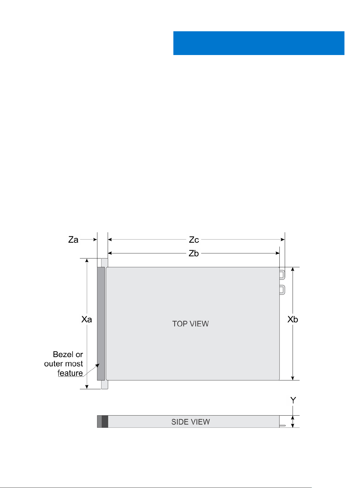
Chassis dimensions
Figure 1. Dimensions of PowerEdge R840 system
4 Technical specifications
Page 5
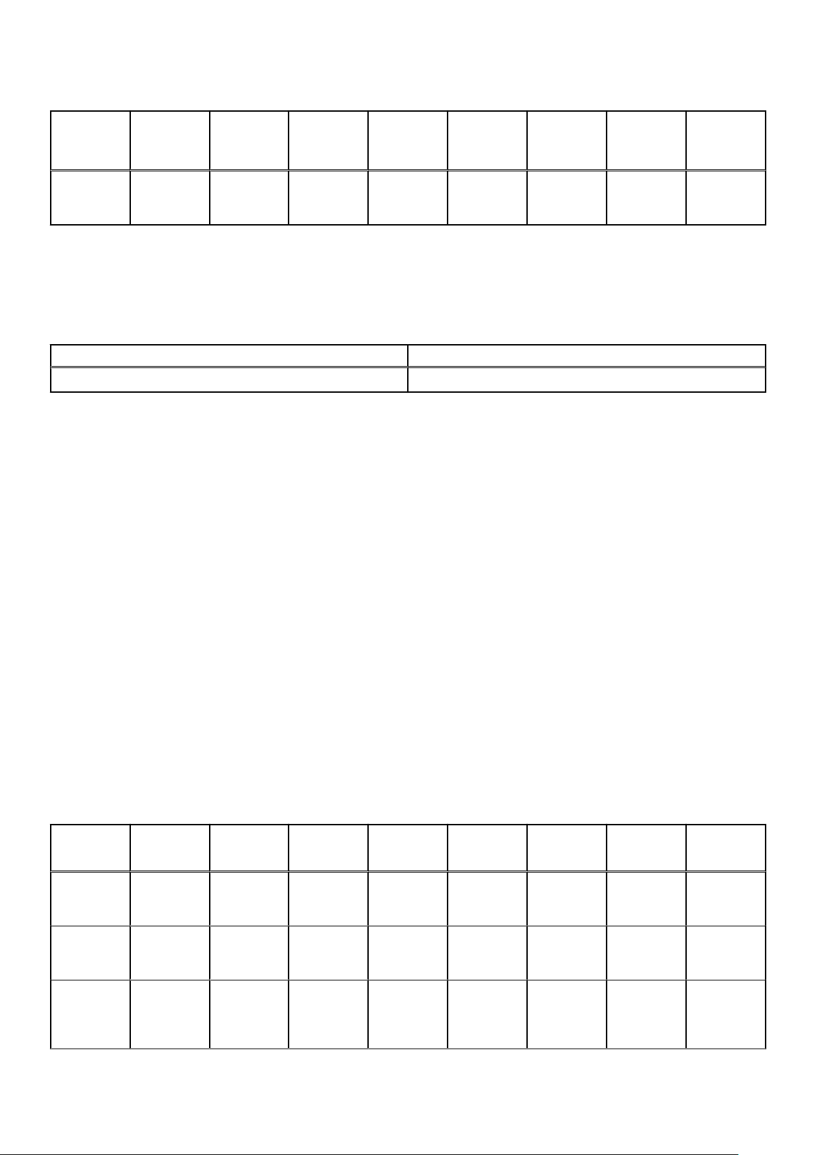
Table 1. Dimensions of PowerEdge R840 system
Xa Xb
482 mm
(18.97
inches)
* - Zb refers to the nominal rear wall external surface, where the system board I/O connectors are located.
(without
brackets)
434 mm
(17.08
inches)
Xb (w
brackets)
444.0 (17.48
inches)
Y Za (with
86.8 mm
(3.41
inches)
bezel)
37.84 mm
(1.41 inches)
Za
(without
bezel)
23.9 mm
(0.94
inches)
Zb* Zc (with
812 mm
(31.96
inches)
PSU
handle)
842 mm
(33.14
inches)
Chassis weight
Table 2. Chassis weight
System Maximum weight (with all drives/SSDs)
2.5 inch 36.6 kg (80.68 lb)
Processor specifications
The PowerEdge R840 system supports four processors - Intel Xeon Scalable Processor family.
Zc (with
chassis
rear wall
handle)
902 mm
(35.51
inches)
Supported operating systems
The PowerEdge R840 supports the following operating systems:
● Canonical Ubuntu LTS
● Citrix Hypervisor
● Microsoft Windows Server with Hyper-V
● Red Hat Enterprise Linux
● SUSE Linux Enterprise Server
● VMware ESXi
For more information on the specific versions and additions, see https://www.dell.com/support/home/Drivers/SupportedOS/
poweredge-r840.
PSU specifications
The PowerEdge R840 system supports up to two AC or DC power supply units (PSUs).
Table 3. PSU specifications
PSU Class Heat
dissipation
(maximum)
750 W AC Platinum 2891
BTU/hr
Frequency Voltage High line
50/60 Hz 100–240 V
AC,
autoranging
200V–240
V
750 W 750 W NA 10 A-5 A
Low line
100 V– 140
V
DC Current
750 W AC Titanium 2843
BTU/hr
750 W
Mixed Mode
HVDC (for
China only)
Platinum 2891
BTU/hr
50/60 Hz 200–240 V
AC,
autoranging
50/60 Hz 100–240 V
AC,
autoranging
750 W NA NA 5 A
750 W 750 W NA 10 A-5 A
Technical specifications 5
Page 6
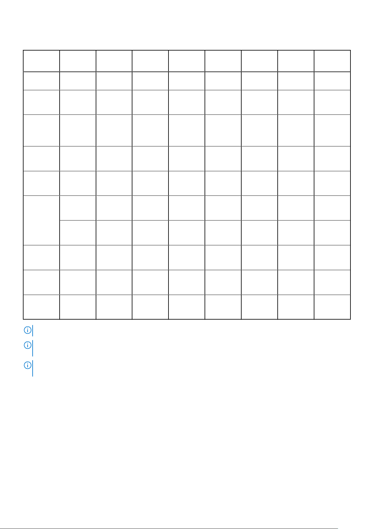
Table 3. PSU specifications
PSU Class Heat
dissipation
(maximum)
Frequency Voltage High line
200V–240
V
Low line
100 V– 140
V
DC Current
N/A 2891
BTU/hr
750 W
Mixed Mode
AC
750 W
Mixed Mode
DC (for
China only)
1100 W AC Platinum 4100
1100 W DC N/A 4416
1100 W 10
A-5 A Mixed
Mode HVDC
(for China
and Japan
only)
1600 W AC Platinum 6000
Platinum 2891
BTU/hr
N/A 2891
BTU/hr
BTU/hr
BTU/hr
Platinum 4100
BTU/hr
N/A 4100
BTU/hr
BTU/hr
N/A 240 V DC,
autoranging
50/60 Hz 100–240 VAC750 W 750 W N/A 10 A-5 A
50/60 Hz 240 V DC 750 W N/A 750 W 5 A
50/60 Hz 100–240 V
AC,
autoranging
N/A –(48–60) V
DC,
autoranging
50/60 Hz 100–240 V
AC,
autoranging
N/A 200–380 V
DC,
autoranging
50/60 Hz 100–240 V
AC,
autoranging
NA NA 750 W 4.5 A
1100 W 1050 W NA 12 A-6.5 A
NA NA 1100 W 32 A
1100 W 1050 W NA 12 A-6.5 A
NA NA 1100 W 6.4 A-3.2 A
1600 W 800 W NA 10 A
2000 W AC Platinum 7500
BTU/hr
2400 W AC Platinum 9000
BTU/hr
NOTE: Heat dissipation is calculated using the PSU wattage rating.
NOTE: This system is also designed to connect to the IT power systems with a phase-to-phase voltage not exceeding 240
V.
NOTE: PSUs rated for 1100 W AC or 1100 W Mixed Mode HVDC and higher require high-line voltage (200–240 V AC) to
supply their rated capacity.
50/60 Hz 100–240 V
AC,
autoranging
50/60 Hz 100–240 V
AC,
autoranging
2000 W 1000 W NA 11.5 A
2400 W 1400 W NA 16 A
System battery specifications
The PowerEdge R840 system supports CR 2032 3.0-V lithium coin cell system battery.
Expansion card riser specifications
The PowerEdge R840 system supports up to six PCI express (PCIe) generation 3 expansion cards that can be installed on the
system board and expansion card risers.
6
Technical specifications
Page 7
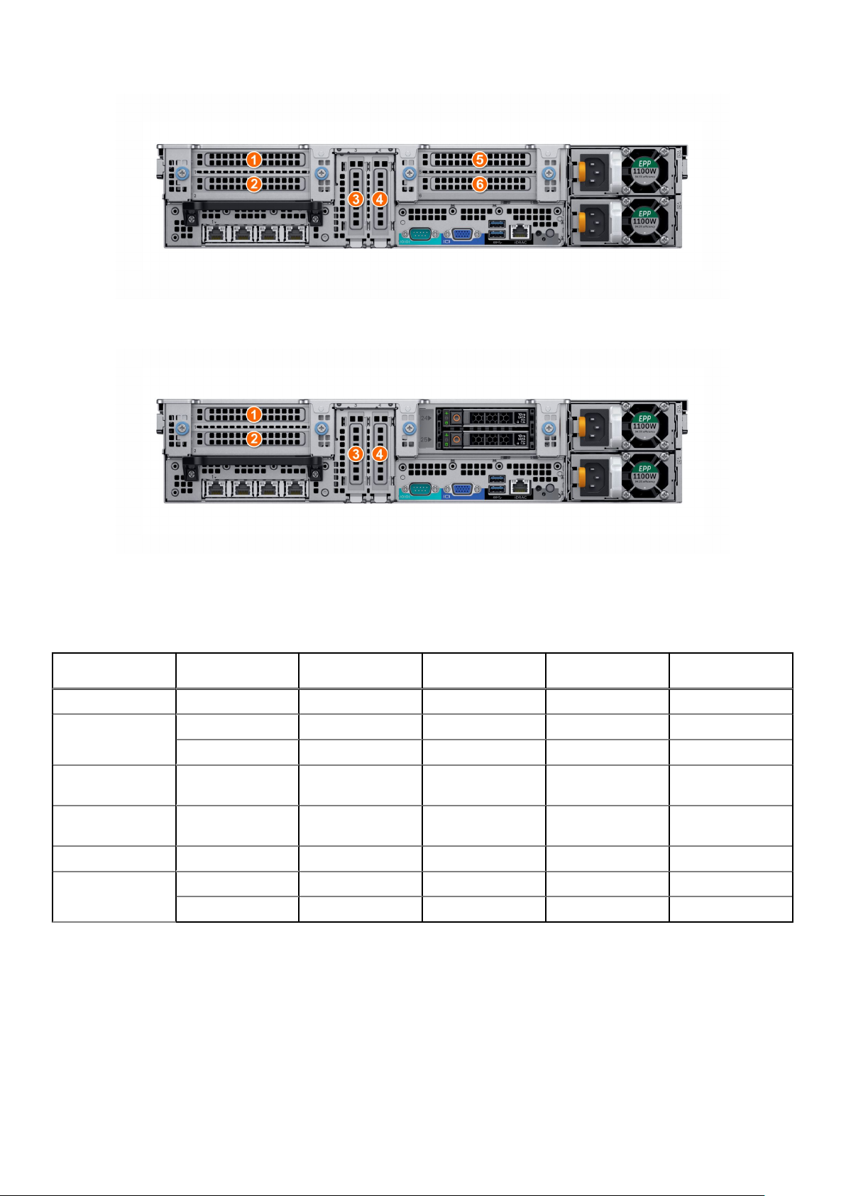
Figure 2. 24 x 2.5-inch drive system
Figure 3. 24 x 2.5-inch + 2 x 2.5-inch (rear) drive system
The following table provides detailed information about the expansion card riser specifications:
Table 4. Expansion card riser specifications
PCIe slot Riser Processor
1 X8 PCIe Riser 1 Processor 1 Full height Half length x8
2 X16 PCIe Riser 1 Processor 1 Full height Full length x16
X8 PCIe Riser 1 Processor 1 Full height Half length x8
3 On the system
board
4 On the system
board
5 X8 PCIe Riser 2 Processor 2 Full height Half length x8
6 X16 PCIe Riser 2 Processor 2 Full height Full length x16
X8 PCIe Riser 2 Processor 2 Full height Half length x8
connection
Processor 1 Low profile Half length x16
Processor 2 Low profile Half length x16
Memory specifications
.
Table 5. Memory specifications
Height Length Slot width
Technical specifications 7
Page 8
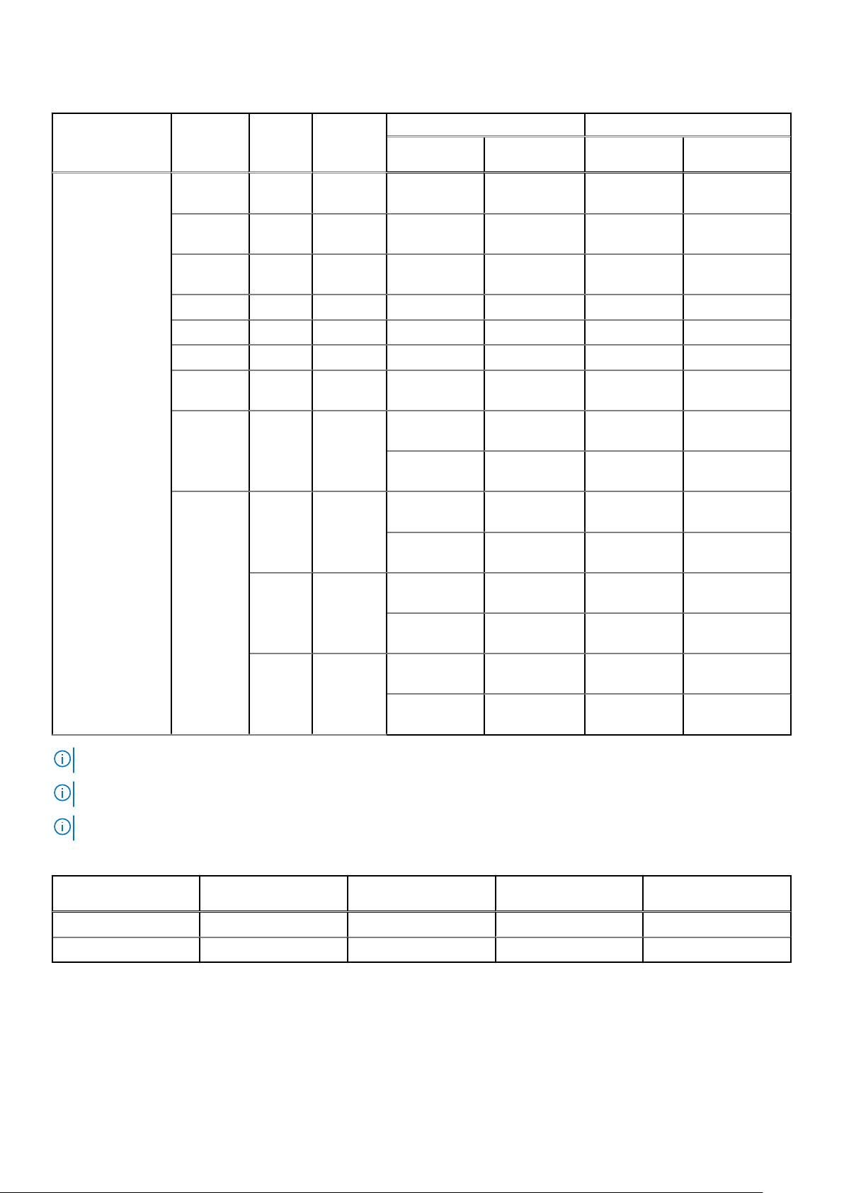
Table 5. Memory specifications
Memory module
sockets
DIMM
type
DIMM
rank
DIMM
capacity
Dual processors Quad processors
Minimum
RAM
Maximum
RAM
Minimum
RAM
Maximum RAM
48 288-pins LRDIMM Octal
rank
LRDIMM Octal
rank
LRDIMM
RDIMM Dual rank 64 GB 128 GB 1536 GB 256 GB 3072 GB
RDIMM Dual rank 32 GB 64 GB 768 GB 128 GB 1536 GB
RDIMM Dual rank 16 GB 32 GB 384 GB 64 GB 768 GB
RDIMM Single
NVDIMM-N Single
DCPMM N/A 128 GB RDIMM: 192GBLRDIMM: 1536GBRDIMM: 384GBLRDIMM: 3072
Quad
rank
rank
rank
N/A 256 GB RDIMM: 384GBLRDIMM: 1536GBRDIMM: 384GBLRDIMM: 3072
256 GB 512 GB 6144 GB 1024 GB 12.288 TB
128 GB 256 GB 3072 GB 512 GB 6144 GB
64 GB 128 GB 1536 GB 256 GB 3072 GB
8 GB 16 GB 192 GB 32 GB 384 GB
16 GB RDIMM: 192GBRDIMM: 384GBRDIMM: 384GBRDIMM: 1152 GB
NVDIMM-N: 16GBNVDIMM-N:
192 GB
DCPMM: 1536GBDCPMM: 1536GBDCPMM: 248GBDCPMM: 3072
NVDIMM-N: 16GBNVDIMM-N: 192
GB
GB
GB
GB
DCPMM: 2048GBDCPMM: 3072GBDCPMM: 4096GBDCPMM: 6144
GB
N/A 512 GB RDIMM: 384GBLRDIMM: 1536GBRDIMM: 768GBLRDIMM: 3072
GB
DCPMM: 4096GBDCPMM: 6144GBDCPMM: 8192GBDCPMM: 12,288
GB
NOTE: Do not mix 8 GB RDIMMs and 16 GB NVDIMM-Ns.
NOTE: Do not mix 64 GB LRDIMMs, 128 GB LRDIMMs and 256 GB LRDIMMs.
NOTE: The maximum ambient temperature for 256 GB LRDIMMs is 30oC.
Table 6. DIMM blank population rules
Processor
configuration
Dual processor Required Required Not required Not required
Quad processor Required Required Required Required
Processor 1 Processor 2 Processor 3 Processor 4
RAID controller specifications
The PowerEdge R840 system supports:
● Internal storage controller cards: PowerEdge RAID Controller (PERC) H330, PERC H730P, H740P, HBA330, and Boot
Optimized Server Storage (BOSS-S1)
8
Technical specifications
Page 9
● External storage controller cards: S140 and 12 Gbps SAS HBA
Drive specifications
Drives
The PowerEdge R840 system supports SAS, SATA, Nearline SAS hard drives/SSDs, or NVMe drives.
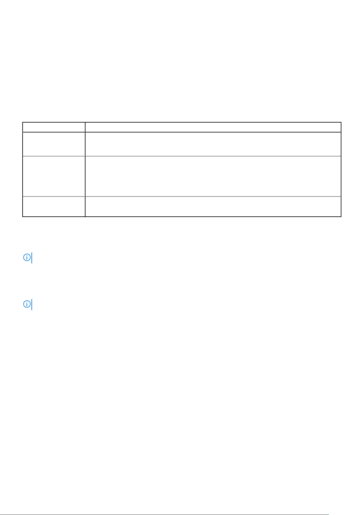
Table 7. Supported drive options for PowerEdge R840 system
Chassis options Configurations
Eight hard drive
chassis
Twenty-four drive
chassis
Twenty four front +
two rear drive chassis
Up to eight 2.5-inch SAS/SATA front accessible drives in slots 0–7
Up to eight 2.5-inch SATA front accessible drives in slots 0–7
Up to twenty-four 2.5-inch SAS/SATA front accessible drives in slots 0–23
Up to twelve 2.5-inch SAS/SATA front accessible drives in slots 0–11 + twelve SAS/SATA/NVMe
front accessible drives in slots 12–23
Up to twenty-four 2.5-inch NVMe front accessible drives in slots 0–23
Up to twenty-four 2.5 inch SAS/SATA front accessible drives in slots 0–23 + up to two 2.5-inch
SAS/SATA rear accessible drives
Optical drives
The PowerEdge R840 system supports one optional slim SATA DVD-ROM drive or DVD +/-RW drive.
NOTE: DVD devices support only data.
Tape drives
The PowerEdge R840 system supports external tape backup devices.
NOTE: The PowerEdge R840 system does not support internal tape drives.
Supported external tape drives:
● External RD1000 USB
● External LTO-5, LTO-6,LTO-7, and 6 Gb SAS tape drives
● 114X rack mount chassis with LTO-5, LTO-6, and LTO-7, 6 Gb SAS tape drives
● TL1000 with LTO-5, LTO-6, and LTO-7 6 Gb SAS tape drives
● TL2000 with LTO-5, LTO-6, and LTO-7 6 Gb SAS tape drives
● TL2000 with LTO-5, LTO-6, and LTO-7 8 Gb FC tape drives
● TL4000 with LTO-5, LTO-6, and LTO-7 6 Gb SAS tape drives
● TL4000 with LTO-5, LTO-6, and LTO-7 8 Gb FC tape drives
● ML6000 with LTO-5, LTO-6, 6 Gb SAS tape drives
● ML6000 with LTO-5, LTO-6, LTO-7 8 Gb FC tape drives
Ports and connectors specifications
USB ports
The PowerEdge R840 system supports both USB 2.0-compliant ports and USB 3.0-compliant ports:
The following table provides more information about the USB specifications:
Technical specifications
9
Page 10
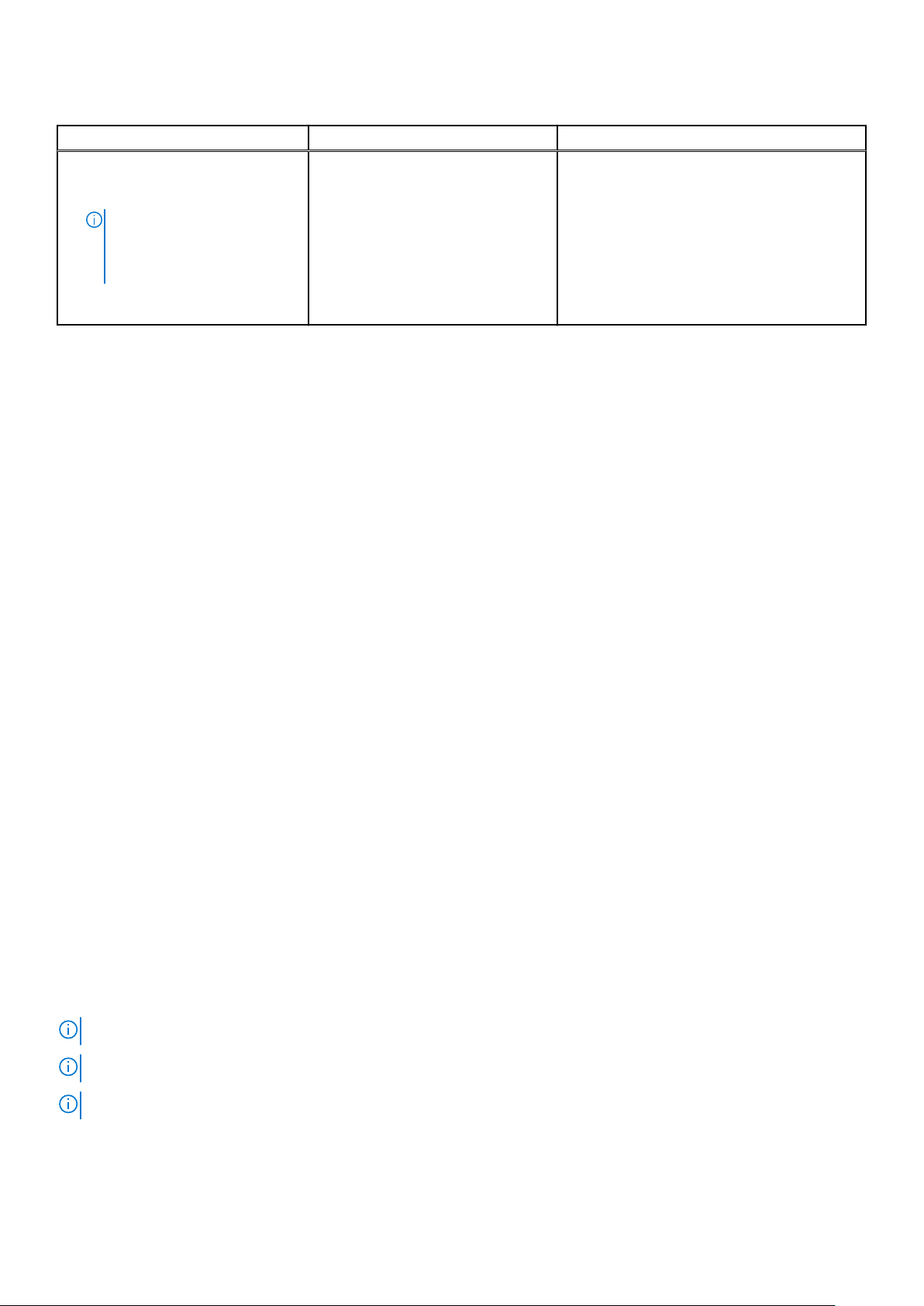
Table 8. USB specifications
Front panel Back panel Internal USB
● Two USB 2.0-compliant ports
● One micro USB 2.0-compliant port
for iDRAC Direct
NOTE: The micro USB 2.0
compliant port can only be
used as an iDRAC Direct or a
management port.
● One optional USB 3.0-compliant
port
● Two USB 3.0-compliant ports ● One internal USB 3.0-compliant port
NIC ports
The PowerEdge R840 system supports up to four Network Interface Controller (NIC) ports that are integrated on the network
daughter card (NDC), and are available in the following configurations:
● Four RJ-45 ports that support 10 Mbps, 100 Mbps, and 1000 Mbps
● Four RJ-45 ports that support 100 M, 1 G, and 10 Gbps
● Four RJ-45 ports, where two ports support maximum of 10 G and the other two ports maximum of 1 G
● Two RJ-45 ports that support up to 1 Gbps and 2 SFP+ ports that support up to 10 Gbps
● Four SFP+ ports that support up to 10 Gbps
● Two SFP28 ports that support up to 25 Gbps
VGA ports
The Video Graphic Array (VGA) port enables you to connect the system to a VGA display.
The PowerEdge R840 system supports two 15-pin VGA ports, one each, on the front and back of the system.
Serial connector
The serial connector on the rear of system for serial device connection and console redirection.
The PowerEdge R840 system supports one serial connector on the back panel, which is a 9-pin connector, Data Terminal
Equipment (DTE), 16550-compliant.
IDSDM or vFlash module
The PowerEdge R840 system supports optional Internal Dual SD module (IDSDM) or vFlash module. In 14th generation of
PowerEdge servers, IDSDM or vFlash module is combined into a single card module, and are available in these configurations:
● vFlash or
● vFlash and IDSDM
The IDSDM or vFlash module is located in a slot on the back of the system. The module supports three microSD cards; two
cards for IDSDM and one card for vFlash. The following capacities are supported:
● IDSDM: 16 GB, 32 GB, 64 GB
● vFlash: 16 GB
NOTE: There are two dip switches on the IDSDM or vFlash module for write-protection.
NOTE: One IDSDM card slot is dedicated for redundancy.
NOTE: Use Dell branded microSD cards associated with the IDSDM or vFlash configured systems.
10 Technical specifications
Page 11
Video specifications
R840 servers support the integrated Matrox G200eW3 graphics controller with 16 MB of video frame buffer.
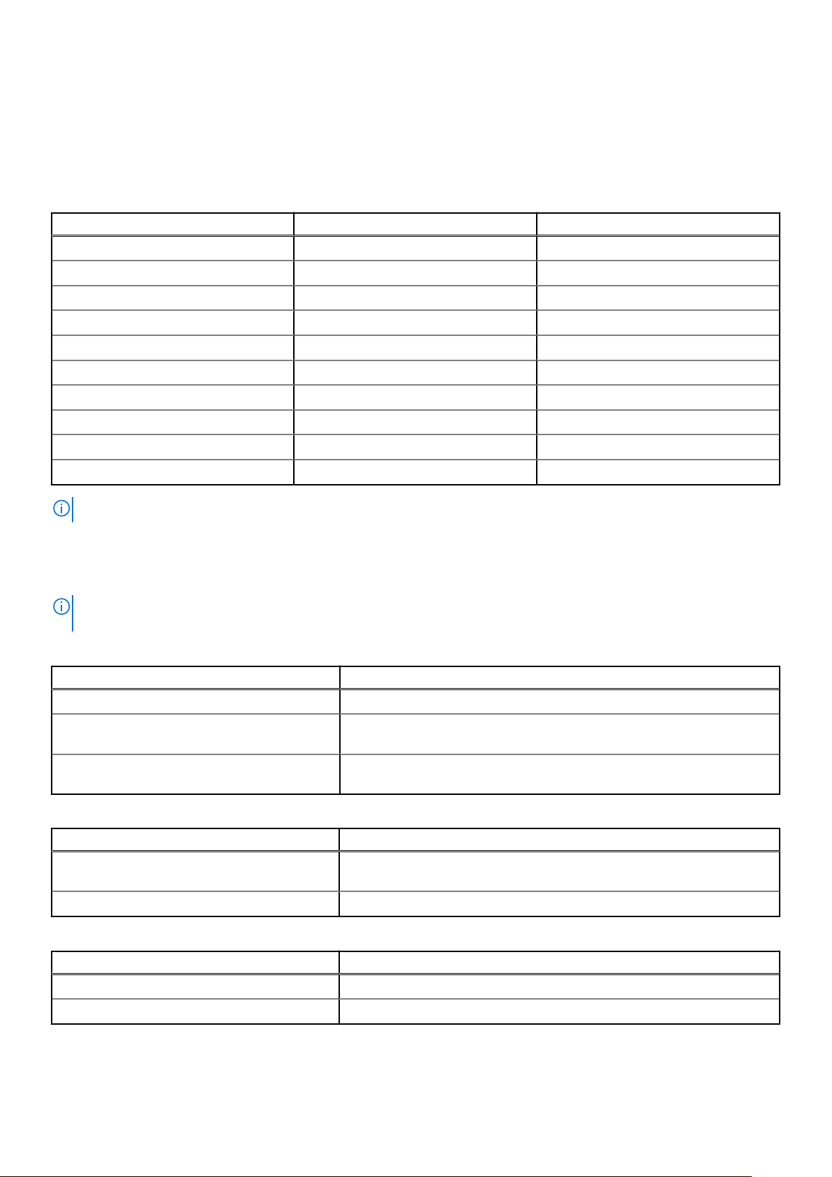
The following table describes the supported video resolution options.
Table 9. Supported video resolution options
Resolution Refresh rate (Hz) Color depth (bits)
1024 x 768 60 8, 16, 32
1280 x 800 60 8, 16, 32
1280 x 1024 60 8, 16, 32
1360 x 768 60 8, 16, 32
1440 x 900 60 8, 16, 32
1600 x 900 60 8, 16, 32
1600 x 1200 60 8, 16, 32
1680 x 1050 60 8, 16, 32
1920 x 1080 60 8, 16, 32
1920 x 1200 60 8, 16, 32
NOTE: 1920 x 1080 and 1920 x 1200 resolutions are supported only in reduced blanking mode.
Environmental specifications
NOTE:
For additional information about environmental certifications, please refer to the Product Environmental Datasheet
located with the Manuals & Documents on support.dell.com.
Table 10. Temperature specifications
Temperature Specifications
Storage –40–65°C (–40 °F–149°F)
Continuous operation (for altitude less than 950
m or 3117 ft)
Maximum temperature gradient (operating and
storage)
Table 11. Relative humidity specifications
Relative humidity Specifications
Storage 5% to 95% RH with 33°C (91°F) maximum dew point. Atmosphere must be
Operating 10% to 80% RH with 29°C (84.2°F) maximum dew point.
Table 12. Maximum vibration specifications
Maximum vibration Specifications
10–35°C (50 °F–95°F) with no direct sunlight on the equipment
20°C/h (36°F/h)
noncondensing at all times.
Operating 0.26 G
Storage 1.88 G
Table 13. Maximum shock pulse specifications
at 5 Hz to 350 Hz (all operation orientations)
rms
at 10 Hz to 500 Hz for 15 minutes (all six sides tested)
rms
Technical specifications 11
Page 12
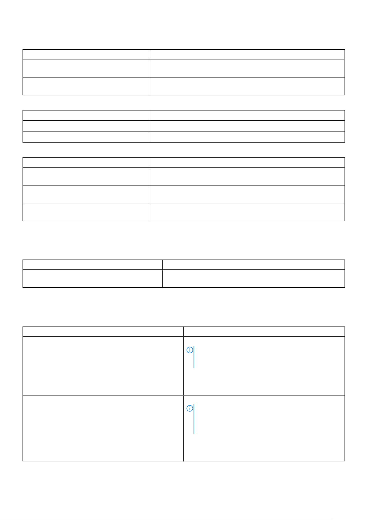
Table 13. Maximum shock pulse specifications
Maximum shock pulse Specifications
Operating Six consecutively executed shock pulses in the positive and negative x, y,
and z axes of 6 G for up to 11 ms.
Storage Six consecutively executed shock pulses in the positive and negative x, y,
and z axes (one pulse on each side of the system) of 71 G for up to 2 ms.
Table 14. Maximum altitude specifications
Maximum altitude Specifications
Operating 3048 m (10,000 ft)
Storage 12,000 m (39,370 ft)
Table 15. Operating temperature derating specification
Operating temperature derating Specifications
Up to 35°C (95°F) Maximum temperature is reduced by 1°C/300 m (1°F/547 ft), above 950
m (3,117 ft).
35–40 °C (95–104 °F) Maximum temperature is reduced by 1°C/175 m (1°F/319 ft), above 950 m
(3,117 ft).
40–45 °C (104 °F–113 °F) Maximum temperature is reduced by 1°C/125 m (1°F/228 ft), above 950 m
(3,117 ft).
Standard operating temperature
Table 16. Standard operating temperature specifications
Standard operating temperature Specifications
Continuous operation (for altitude less than 950 m or
3117 ft)
10 °C–35°C (50 °F–95°F) with no direct sunlight on the equipment.
Expanded operating temperature
Table 17. Expanded operating temperature specifications
Expanded operating temperature Specifications
Continuous operation 5 °C–40°C at 5% to 85% RH with 29°C dew point.
NOTE: Outside the standard operating temperature (10
°C–35°C), the system can operate continuously in
temperatures as low as 5°C and as high as 40°C.
For temperatures 35 °C – 40°C, derate maximum allowable
temperature by 1°C per 175 m (1°F per 319 ft.) above 950 m
(3,1171 ft.).
≤ 1% of annual operating hours –5 °C–45°C at 5% to 90% RH with 29°C dew point.
NOTE: Outside the standard operating temperature (10
°C–35°C), the system can operate down to –5°C or up
to 45°C for a maximum of 1% of its annual operating
hours.
12 Technical specifications
For temperatures 40 °C – 45°C, derate maximum allowable
temperature by 1°C per 125 m (1°F per 228 ft.) above 950 m
(3.117 ft.).
Page 13
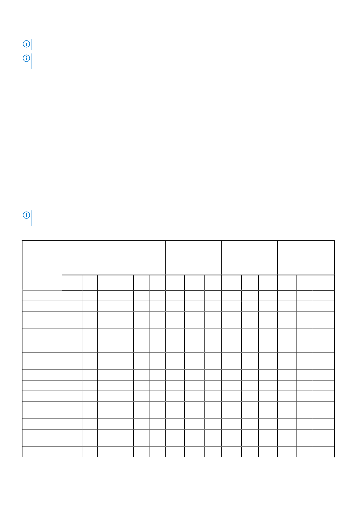
NOTE: When operating in the expanded temperature range, the performance of the system may be impacted.
NOTE: When operating in the expanded temperature range, ambient temperature warnings may be reported on the LCD
panel and in the System Event Log.
Expanded operating temperature restrictions
● The operating temperature is specified for a maximum altitude of 950 m for Fresh Air Cooling.
● Do not perform cold start below 5°C due to hard drive constraints.
● Apache Pass DIMM, NVDIMM, PCIe SSD, and NVMe are not supported.
● Tape Backup Unit (TBU) is not supported in Fresh Air.
● LRDIMM >32 GB is not supported in x4 sockets configuration.
● Rear installed drives and GPU configuration are not supported.
● Redundant power supplies are required.
● Non Dell qualified peripheral cards and /or peripheral cards greater than 25 W are not supported.
● Intel FPGA is not supported.
● 205 W SKUs, 200W/18C, 165W/12C, and 150W_8C processor are not supported on all x4 socket processor configurations.
● 165 W SKUs, 130W/8C, 115W/6C, and 105W_4C are not supported on the x4 socket processor configurations except front
x8 inch SAS/SATA drives configurations.
Ambient temperature limitations
NOTE:
The ambient temperature limit must be adhered to ensure proper cooling and to avoid excess processor throttling,
which may impact system performance.
Table 18. Configuration-based ambient temperature restrictions with GPGPU
TDP(W) R840
● 8 x 2.5 inch
SAS/SATA
● 2 x CPU
● 2 x GPGPU
C40E4535 30 C40E4535 30 C40E4535 30 C40E4535 30 C40E4535 30
205 N N N N N N N N N N N N N N N
200 N N N N N N N N N N N N N N N
165 (Gold
6146)
150 (Gold
6144 and
6244)
150 (Gold
6240Y)
165 N Y Y N Y Y N Y Y N N Y N N Y
150 N Y Y N Y Y N Y Y N N Y N N Y
140 N Y Y N Y Y N Y Y N N Y N N Y
130 ( Gold
6134)
N N N N N N N N N N N N N N N
N N N N N N N N N N N N N N N
N N N N N N N N N N N Y N N Y
N Y Y N Y Y N Y Y N N Y N N Y
R840
● 8 x 2.5 inch
SAS/SATA
● 4 x CPU
● 2 x GPGPU
R840
● 24 x 2.5 inch
SAS/SATA
● 2 x CPU
● 2 x GPGPU
R840
● 24 x 2.5 inch
SAS/SATA
● 4 x CPU
● 2 x GPGPU
R840
● 24 x 2.5 inch
NVme
● 4 x CPU
● 2 x GPGPU
125 N Y Y N Y Y N Y Y N N Y N N Y
115 ( Gold
6128)
115 N Y Y N Y Y N Y Y N N Y N N Y
N Y Y N Y Y N Y Y N N Y N N Y
Technical specifications 13
Page 14
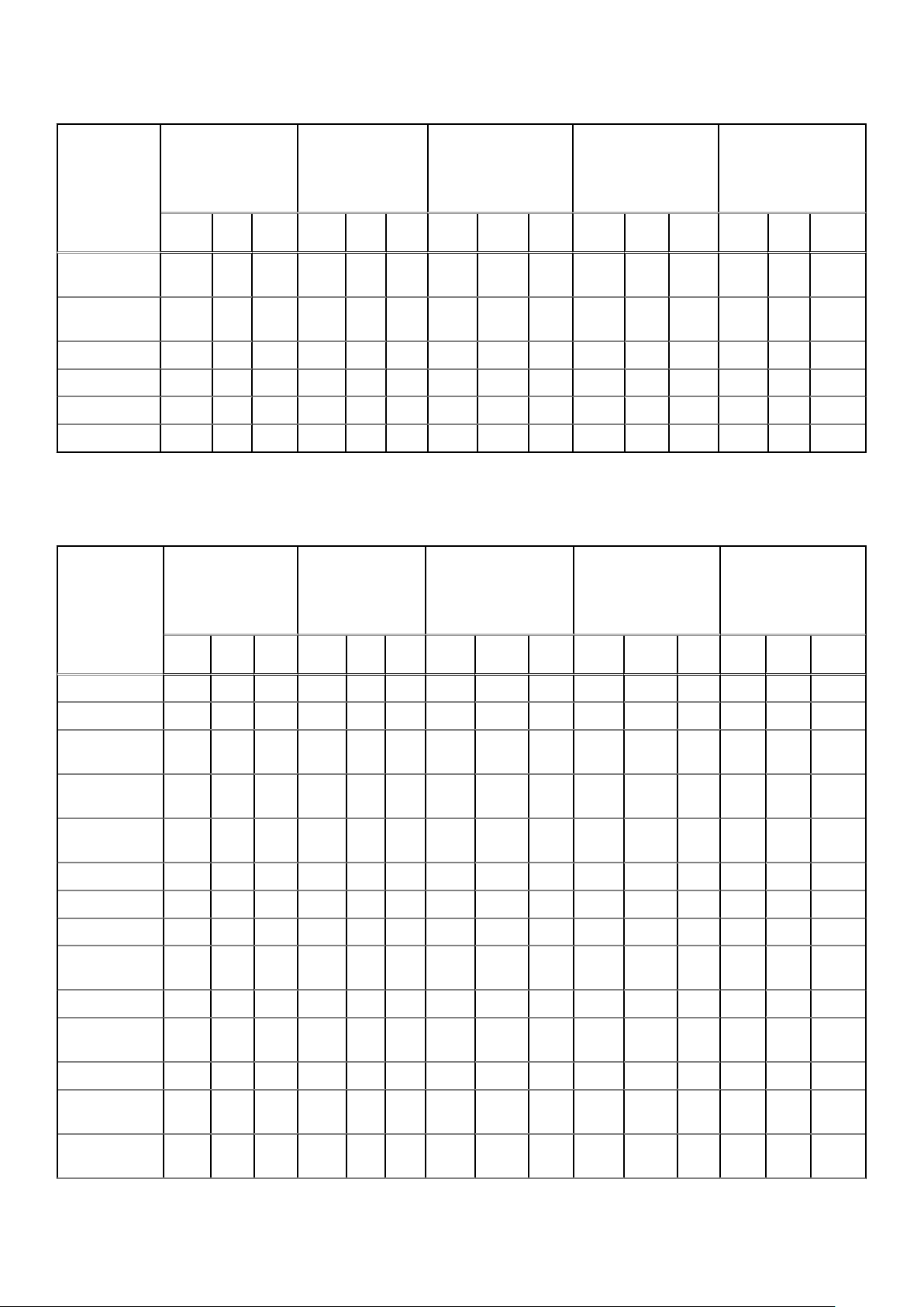
Table 18. Configuration-based ambient temperature restrictions with GPGPU
TDP(W) R840
● 8 x 2.5 inch
SAS/SATA
● 2 x CPU
● 2 x GPGPU
C40E4535 30 C40E4535 30 C40E4535 30 C40E4535 30 C40E4535 30
R840
● 8 x 2.5 inch
SAS/SATA
● 4 x CPU
● 2 x GPGPU
R840
● 24 x 2.5 inch
SAS/SATA
● 2 x CPU
● 2 x GPGPU
R840
● 24 x 2.5 inch
SAS/SATA
● 4 x CPU
● 2 x GPGPU
R840
● 24 x 2.5 inch
NVme
● 4 x CPU
● 2 x GPGPU
105(Gold 5122
and 8156)
105(Gold 5222
and 8256)
105 N Y Y N Y Y N Y Y N N Y N N Y
100 N Y Y N Y Y N Y Y N N Y N N Y
85 N Y Y N Y Y N Y Y N N Y N N Y
70 N Y Y N Y Y N Y Y N N N N N N
N= Not Supported
Y= Supported
N Y Y N Y Y N Y Y N N Y N N Y
N Y Y N Y Y N Y Y N N Y N N Y
Table 19. Configuration-based ambient temperature restrictions with PCIe
TDP(W) R840
● 8 x 2.5 inch
SAS/SATA
● 2 x CPU
● 6 x PCIe
C40E4535 30 C40E4535 30 C40E4535 30 C40E4535 30 C40
205 Y Y Y N Y Y Y Y Y N N Y N N Y
200 Y Y Y N Y Y Y Y Y N N Y N N Y
R840
● 8 x 2.5 inch
SAS/SATA
● 4 x CPU
● 6 x PCIe
R840
● 24 x 2.5 inch
SAS/SATA
● 2 x CPU
● 6 x PCIe
R840
● 24 x 2.5 inch
SAS/SATA
● 4 x CPU
● 6 x PCIe
R840
● 24 x 2.5 inch
NVMe
● 4 x CPU
● 6 x PCIe
35 30
E45
165 (Gold
6146)
150 (Gold 6144
and 6244)
150 (Gold
6240Y)
165 Y Y Y Y Y Y Y Y Y N Y Y N N Y
150 Y Y Y Y Y Y Y Y Y Y Y Y N Y Y
140 Y Y Y Y Y Y Y Y Y Y Y Y N Y Y
130 ( Gold
6134)
125 Y Y Y Y Y Y Y Y Y Y Y Y N Y Y
115 ( Gold
6128)
115 Y Y Y Y Y Y Y Y Y Y Y Y N Y Y
105(Gold 5122
and 8156)
105(Gold 5222
and 8256)
Y Y Y N Y Y Y Y Y N N Y N N Y
Y Y Y N Y Y Y Y Y N N Y N N Y
Y Y Y N Y Y Y Y Y N Y Y N N Y
Y Y Y Y Y Y Y Y Y N Y Y N N Y
Y Y Y Y Y Y Y Y Y N Y Y N N Y
Y Y Y Y Y Y Y Y Y N Y Y N N Y
Y Y Y Y Y Y Y Y Y N Y Y N N Y
14 Technical specifications
Page 15
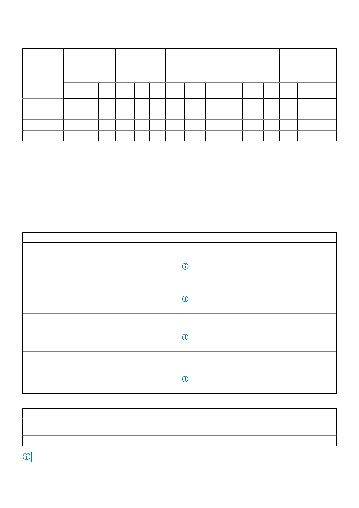
Table 19. Configuration-based ambient temperature restrictions with PCIe
TDP(W) R840
● 8 x 2.5 inch
SAS/SATA
● 2 x CPU
● 6 x PCIe
C40E4535 30 C40E4535 30 C40E4535 30 C40E4535 30 C40
105 Y Y Y Y Y Y Y Y Y Y Y Y N Y Y
100 Y Y Y Y Y Y Y Y Y Y Y Y N Y Y
85 Y Y Y Y Y Y Y Y Y Y Y Y N Y Y
70 Y Y Y Y Y Y Y Y Y Y Y Y N Y Y
N= Not Supported
Y= Supported
R840
● 8 x 2.5 inch
SAS/SATA
● 4 x CPU
● 6 x PCIe
R840
● 24 x 2.5 inch
SAS/SATA
● 2 x CPU
● 6 x PCIe
R840
● 24 x 2.5 inch
SAS/SATA
● 4 x CPU
● 6 x PCIe
R840
● 24 x 2.5 inch
NVMe
● 4 x CPU
● 6 x PCIe
35 30
E45
Particulate and gaseous contamination specifications
The following table defines the limitations that help avoid any damages to the IT equipment and/or, or both failure from
particulates and gaseous contamination. If the levels of particulates or gaseous pollution exceed the specified limitations and
result in equipment damage or failure, you must rectify the environmental conditions. Remediation of environmental conditions is
the responsibility of the customer.
Table 20. Particulate contamination specifications
Particulate contamination Specifications
Air Filtration
Conductive dust Air must be free of conductive dust, zinc whiskers, or other
Corrosive dust
Data center air filtration as defined by ISO Class 8 per ISO
14644-1 with a 95% upper confidence limit.
NOTE: This condition applies to data center environments
only. Air filtration requirements do not apply to IT
equipment designed to be used outside a data center, in
environments such as an office or factory floor.
NOTE: Air entering the data center must have MERV11 or
MERV13 filtration.
conductive particles.
NOTE: This condition applies to data center and non-data
center environments.
● Air must be free of corrosive dust.
● Residual dust present in the air must have a deliquescent
point less than 60% relative humidity.
NOTE: This condition applies to data center and non-data
center environments.
Table 21. Gaseous contamination specifications
Gaseous contamination Specifications
Copper Coupon Corrosion <300 Å/month per Class G1 as defined by ANSI/
ISA71.04-1985.
Silver Coupon Corrosion <200 Å/month as defined by AHSRAE TC9.9.
NOTE: Maximum corrosive contaminant levels measured at ≤50% relative humidity.
Technical specifications 15
 Loading...