

Dell R6515 Installation Manual

Dell EMC PowerEdge R6515
Installation and Service Manual
Reg ula tor y M ode l: E45 S S eries
Reg ula tor y T ype : E 45S 003
Apr il 202 1
Rev . A 09

Notes, cautions, and warnings
NOTE: A NOTE indicates important information that helps you make better use of your product.
CAUTION: A CAUTION indicates either potential damage to hardware or loss of data and tells you how to avoid
the problem.
WARNING: A WARNING indicates a potential for property damage, personal injury, or death.
© 2019- 2021 Dell Inc. or its subsidiaries. All rights reserved. De ll, EM C, and other trademarks are trademarks of Dell Inc. or its subsidia rie s.
Other trademarks may be trademarks of their respective owners.

Contents
Chapter 1: About this document.................................................................................................... 7
Chapter 2: PowerEdge R6515 system overview............................................................................. 8
Front view of the system...................................................................................................................................................8
Left control panel view................................................................................................................................................ 11
Right control panel view............................................................................................................................................. 12
Rear view of the system.................................................................................................................................................. 12
Inside the system .............................................................................................................................................................. 14
Locating the Express Service Code and Service Tag............................................................................................... 14
System information label.................................................................................................................................................. 15
Rail sizing and rack compatibility matrix.......................................................................................................................19
Chapter 3: Initial system setup and configuration........................................................................20
Setting up the system......................................................................................................................................................20
iDRAC configuration......................................................................................................................................................... 20
Options to set up iDRAC IP address.......................................................................................................................20
Options to log in to iDRAC......................................................................................................................................... 21
Resources to install operating system......................................................................................................................... 22
Options to download firmware ................................................................................................................................22
Options to download and install OS drivers .........................................................................................................22
Downloading drivers and firmware.......................................................................................................................... 23
Chapter 4: Installing and removing system components.............................................................. 24
Safety instructions............................................................................................................................................................24
Before working inside your system............................................................................................................................... 25
After working inside your system.................................................................................................................................. 25
Recommended tools......................................................................................................................................................... 25
Optional front bezel.......................................................................................................................................................... 26
Removing the front bezel.......................................................................................................................................... 26
Installing the front bezel............................................................................................................................................ 26
System cover......................................................................................................................................................................27
Removing the system cover..................................................................................................................................... 27
Installing the system cover....................................................................................................................................... 28
Drive backplane cover......................................................................................................................................................29
Removing the drive backplane cover..................................................................................................................... 29
Installing the drive backplane cover........................................................................................................................30
Air shroud............................................................................................................................................................................ 32
Removing the air shroud............................................................................................................................................32
Installing the air shroud.............................................................................................................................................. 32
Cooling fan.......................................................................................................................................................................... 33
Removing a cooling fan..............................................................................................................................................33
Installing a cooling fan................................................................................................................................................ 34
Intrusion switch module...................................................................................................................................................35
Removing the intrusion switch.................................................................................................................................35
Contents 3

Installing the intrusion switch...................................................................................................................................36
Drives....................................................................................................................................................................................37
Removing a drive blank.............................................................................................................................................. 37
Installing a drive blank................................................................................................................................................ 38
Removing the drive carrier........................................................................................................................................38
Installing the drive carrier..........................................................................................................................................39
Removing the drive from the drive carrier............................................................................................................ 40
Installing the drive into the drive carrier.................................................................................................................41
Drive backplane..................................................................................................................................................................42
Drive backplane............................................................................................................................................................42
Removing the backplane .......................................................................................................................................... 43
Installing the drive backplane................................................................................................................................... 44
Cable routing...................................................................................................................................................................... 46
System memory................................................................................................................................................................. 47
System memory guidelines........................................................................................................................................ 47
General memory module installation guidelines.................................................................................................... 49
Removing a memory module..................................................................................................................................... 51
Installing a memory module.......................................................................................................................................52
Processor and heat sink.................................................................................................................................................. 53
Removing a heat sink................................................................................................................................................. 53
Removing the AMD processor................................................................................................................................. 54
Installing the AMD processor................................................................................................................................... 56
Installing the heat sink................................................................................................................................................58
Expansion cards and expansion card risers................................................................................................................ 60
Expansion card installation guidelines.................................................................................................................... 60
Removing the expansion card risers....................................................................................................................... 62
Installing the expansion card risers......................................................................................................................... 63
Removing expansion card from the expansion card riser..................................................................................65
Installing an expansion card into the expansion card riser................................................................................ 67
Micro SD card.................................................................................................................................................................... 70
Removing the MicroSD card.....................................................................................................................................70
Installing the MicroSD card....................................................................................................................................... 70
M.2 SSD module................................................................................................................................................................. 71
Removing the M.2 SSD module................................................................................................................................ 71
Installing the M.2 SSD module..................................................................................................................................72
Optional IDSDM module...................................................................................................................................................73
Removing the IDSDM module...................................................................................................................................73
Installing the IDSDM module..................................................................................................................................... 74
LOM riser card................................................................................................................................................................... 75
Removing the LOM riser card.................................................................................................................................. 75
Installing the LOM riser card..................................................................................................................................... 77
Mini PERC card.................................................................................................................................................................. 79
Removing the mini PERC card................................................................................................................................. 79
Installing the mini PERC card................................................................................................................................... 80
System battery ................................................................................................................................................................. 82
Replacing the system battery...................................................................................................................................82
Optional internal USB memory key............................................................................................................................... 83
Replacing optional internal USB memory key....................................................................................................... 83
VGA module........................................................................................................................................................................ 85
Removing the VGA module....................................................................................................................................... 85
4
Contents

Installing the VGA module......................................................................................................................................... 85
Optional optical drive....................................................................................................................................................... 86
Removing the optical drive....................................................................................................................................... 86
Installing the optical drive..........................................................................................................................................87
Power supply unit..............................................................................................................................................................88
Hot spare feature........................................................................................................................................................ 88
Removing a power supply unit blank...................................................................................................................... 89
Installing a power supply unit blank........................................................................................................................ 89
Removing a power supply unit................................................................................................................................. 90
Installing a power supply unit.................................................................................................................................... 91
Power interposer board................................................................................................................................................... 92
Removing the power interposer board...................................................................................................................92
Installing the power interposer board.....................................................................................................................92
System board..................................................................................................................................................................... 93
Removing the system board..................................................................................................................................... 93
Installing the system board....................................................................................................................................... 94
Trusted Platform Module................................................................................................................................................ 96
Upgrading the Trusted Platform Module...............................................................................................................96
Control panel...................................................................................................................................................................... 98
Removing the left control panel.............................................................................................................................. 98
Installing the left control panel.................................................................................................................................99
Removing the right control panel.......................................................................................................................... 100
Installing the right control panel............................................................................................................................. 101
Chapter 5: Jumpers and connectors...........................................................................................103
System board connectors..............................................................................................................................................104
System board jumper settings......................................................................................................................................105
Disabling a forgotten password................................................................................................................................... 105
Chapter 6: System diagnostics and indicator codes................................................................... 106
Status LED indicators.....................................................................................................................................................106
System health and system ID indicator codes..........................................................................................................107
iDRAC Quick Sync 2 indicator codes.......................................................................................................................... 107
iDRAC Direct LED indicator codes.............................................................................................................................. 108
LCD panel.......................................................................................................................................................................... 108
Viewing Home screen............................................................................................................................................... 109
Setup menu................................................................................................................................................................. 109
View menu....................................................................................................................................................................110
NIC indicator codes..........................................................................................................................................................110
Power supply unit indicator codes................................................................................................................................ 111
Drive indicator codes.......................................................................................................................................................112
Using system diagnostics............................................................................................................................................... 112
Dell Embedded System Diagnostics....................................................................................................................... 113
Chapter 7: Getting help.............................................................................................................. 114
Recycling or End-of-Life service information............................................................................................................114
Contacting Dell..................................................................................................................................................................114
Accessing system information by using QRL.............................................................................................................114
Quick Resource Locator for PowerEdge R6515 system...................................................................................115
Contents
5

Receiving automated support with SupportAssist ..................................................................................................115
Chapter 8: Documentation resources..........................................................................................116
6 Contents

About this document
This document provides an overview about the system, information about installing and replacing components, technical
specifications, diagnostic tools, and guidelines to be followed while installing certain components.
1
About this document 7
2
PowerEdge R6515 system overview
The PowerEdge R6515 system is a 1U server that supports:
● One AMD EPYC 7002 series processor
● 16 DIMM slots
● Two redundant AC power supply units
● Up to 4 x 3.5-inch, 8 x 2.5-inch SAS/SATA drives, 10 x 2.5-inch drives (with 8 SAS/SATA/ NVMe drives + 2 NVMe drives)
or 10x 2.5-inch NVMe drives only.
NOTE: For more information about how to hot swap NVMe PCIe SSD U.2 device, see the Dell Express Flash NVMe PCIe
SSD User's Guide at https://www.dell.com/support> Browse all Products > Data Center Infrastructure > Storage
Adapters & Controllers > Dell PowerEdge Express Flash NVMe PCIe SSD > Documentation > Manuals and
Documents.
NOTE: All instances of SAS, SATA drives are referred to as drives in this document, unless specified otherwise.
For more information, see the Dell EMC PowerEdge R6515 Technical Specifications on the product documentation page.
Topics:
• Front view of the system
• Rear view of the system
• Inside the system
• Locating the Express Service Code and Service Tag
• System information label
• Rail sizing and rack compatibility matrix
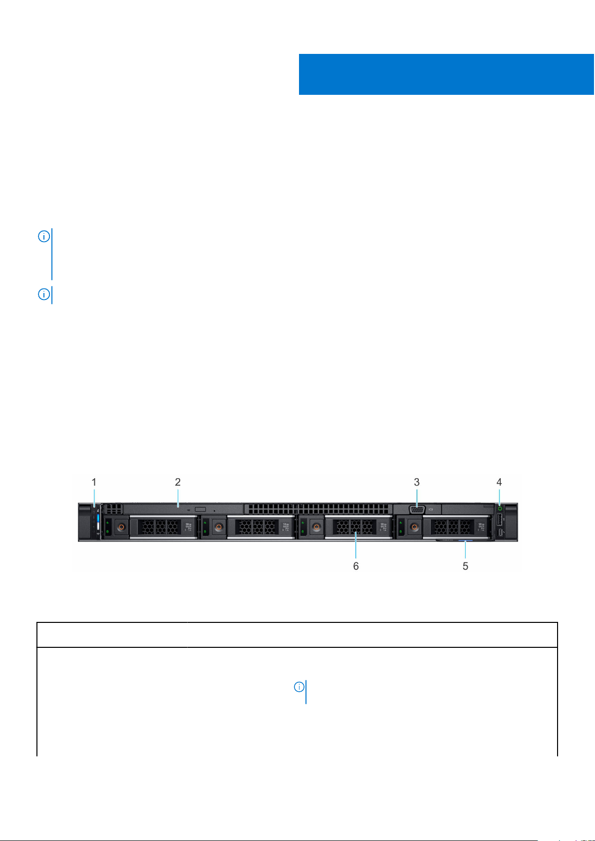
Front view of the system
Figure 1. Front view of 4 x 3.5-inch drive system
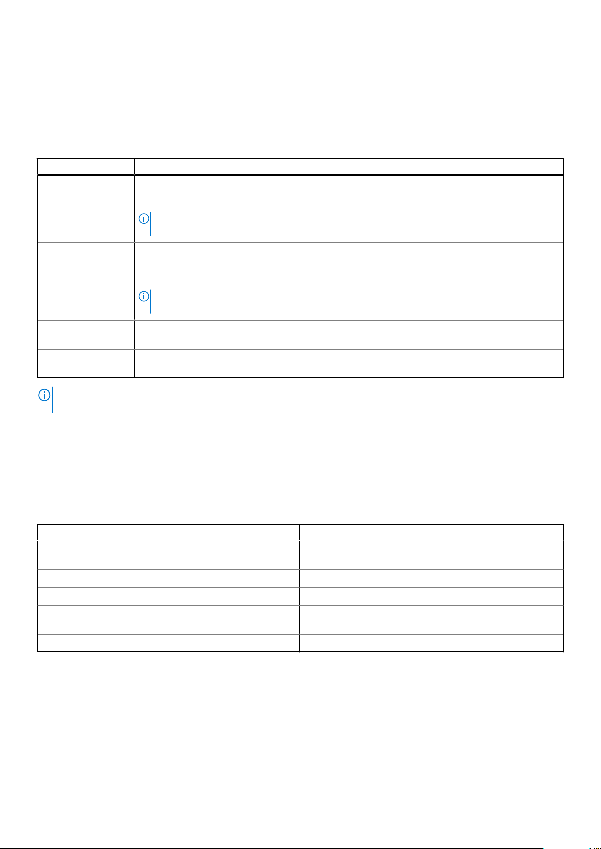
Table 1. Features available on the front of the system
Item Ports, panels, and
slots
1 Left control panel N/A
Icon Description
Contains the system health, system ID, status LED, and the
iDRAC Quick Sync 2 (wireless) indicator.
● Status LED: Enables you to identify any failed hardware
NOTE: The iDRAC Quick Sync 2 indicator is available only
on certain configurations.
components. There are up to five status LEDs and an overall
system health LED (Chassis health and system ID) bar. For
more information, see the Status LED indicators section.
8 PowerEdge R6515 system overview

Table 1. Features available on the front of the system (continued)
Item Ports, panels, and
slots
2 Optical drive (optional) N/A One optional slim SATA DVD-ROM drive or DVD+/-RW drive.
3 VGA port Enables you to connect a display device to the system.
4 Right control panel N/A Contains the power button, USB port, iDRAC Direct micro port,
Icon Description
● Quick Sync 2 (wireless): Indicates a Quick Sync enabled
system. The Quick Sync feature is optional. This feature
allows management of the system by using mobile devices
called as OpenManage Mobile (OMM) feature. Using iDRAC
Quick Sync 2 with OpenManage Mobile (OMM) aggregates
hardware or firmware inventory and various system level
diagnostic and error information that can be used in
troubleshooting the system. For more information, see
the iDRAC User's Guide available at https://www.dell.com/
idracmanuals
and the iDRAC Direct status LED.
5 Information tag
6 Drive (4) N/A
Figure 2. Front view of 8 x 2.5-inch drive system
The Information tag is a slide-out label panel that contains
system information such as Service Tag, NIC, MAC address,
and so on. If you have opted for the secure default access
to iDRAC, the Information tag also contains the iDRAC secure
default password.
Enables you to install drives that are supported on your system.
Table 2. Features available on the front of the system
Item Ports, panels, and
slots
1 Left control panel N/A
Icon Description
Contains the system health, system ID, status LED, and the
iDRAC Quick Sync 2 (wireless) indicator.
NOTE: The iDRAC Quick Sync 2 indicator is available only
on certain configurations.
● Status LED: Enables you to identify any failed hardware
components. There are up to five status LEDs and an overall
system health LED (Chassis health and system ID) bar. For
more information, see the Status LED indicators section.
● Quick Sync 2 (wireless): Indicates a Quick Sync enabled
system. The Quick Sync feature is optional. This feature
allows management of the system by using mobile devices
called as OpenManage Mobile (OMM) feature. Using iDRAC
Quick Sync 2 with OpenManage Mobile (OMM) aggregates
hardware or firmware inventory and various system level
diagnostic and error information that can be used in
troubleshooting the system. For more information, see
the iDRAC User's Guide available at https://www.dell.com/
idracmanuals
PowerEdge R6515 system overview 9
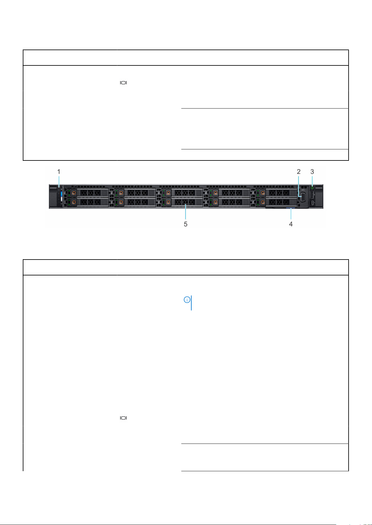
Table 2. Features available on the front of the system
Item Ports, panels, and
slots
2 Optical drive (optional) N/A One optional slim SATA DVD-ROM drive or DVD+/-RW drive.
3 VGA port Enables you to connect a display device to the system.
4 Right control panel N/A Contains the power button, USB port, iDRAC Direct micro port,
Icon Description
and the iDRAC Direct status LED.
5 Information tag
6 Drive (8) N/A
Figure 3. Front view of 10 x 2.5-inch drive system
The Information tag is a slide-out label panel that contains
system information such as Service Tag, NIC, MAC address,
and so on. If you have opted for the secure default access
to iDRAC, the Information tag also contains the iDRAC secure
default password.
Enables you to install drives that are supported on your system.
Table 3. Features available on the front of the system (continued)
Item Ports, panels, and
slots
1 Left control panel N/A
Icon Description
Contains the system health, system ID, status LED, and the
iDRAC Quick Sync 2 (wireless) indicator.
NOTE: The iDRAC Quick Sync 2 indicator is available only
on certain configurations.
● Status LED: Enables you to identify any failed hardware
components. There are up to five status LEDs and an overall
system health LED (Chassis health and system ID) bar. For
more information, see the Status LED indicators section.
● Quick Sync 2 (wireless): Indicates a Quick Sync enabled
system. The Quick Sync feature is optional. This feature
allows management of the system by using mobile devices
called as OpenManage Mobile (OMM) feature. Using iDRAC
Quick Sync 2 with OpenManage Mobile (OMM) aggregates
hardware or firmware inventory and various system level
diagnostic and error information that can be used in
troubleshooting the system. For more information, see
the iDRAC User's Guide available at https://www.dell.com/
idracmanuals
2 VGA port Enables you to connect a display device to the system.
3 Right control panel N/A Contains the power button, USB port, iDRAC Direct micro port,
and the iDRAC Direct status LED.
4 Information tag
The Information tag is a slide-out label panel that contains
system information such as Service Tag, NIC, MAC address,
and so on. If you have opted for the secure default access
10 PowerEdge R6515 system overview

Table 3. Features available on the front of the system
Item Ports, panels, and
slots
Icon Description
to iDRAC, the Information tag also contains the iDRAC secure
default password.
5 Drive (10) N/A
For more information, see the Dell EMC PowerEdge R6515 Technical Specifications on the product documentation page.
Enables you to install drives that are supported on your system.
Left control panel view
Figure 4. Left control panel without optional iDRAC Quick Sync 2.0 indicator
Figure 5. Left control panel with optional iDRAC Quick Sync 2.0 indicator
Table 4. Left control panel
Item Indicator, button, or
1 Status LED indicators N/A
2
3
connector
System health and system ID
indicator
iDRAC Quick Sync 2 wireless
indicator (optional)
Icon Description
Indicates the status of the system. For more information, see the Status LED
indicators section.
Indicates the system health. For more information, see the System health
and system ID indicator codes section.
Indicates if the iDRAC Quick Sync 2 wireless option is activated. The Quick
Sync 2 feature allows management of the system using mobile devices.
This feature aggregates hardware/firmware inventory and various system
level diagnostic/error information that can be used in troubleshooting the
system. You can access system inventory, Dell Lifecycle Controller logs or
system logs, system health status, and also configure iDRAC, BIOS, and
networking parameters. You can also launch the virtual Keyboard, Video, and
Mouse (KVM) viewer and virtual Kernel-based Virtual Machine (KVM), on
a supported mobile device. For more information, see the Integrated Dell
Remote Access Controller User's Guide at www.dell.com/poweredgemanuals
PowerEdge R6515 system overview 11
NOTE: For more information about the indicator codes, see the System diagnostics and indicator codes section.
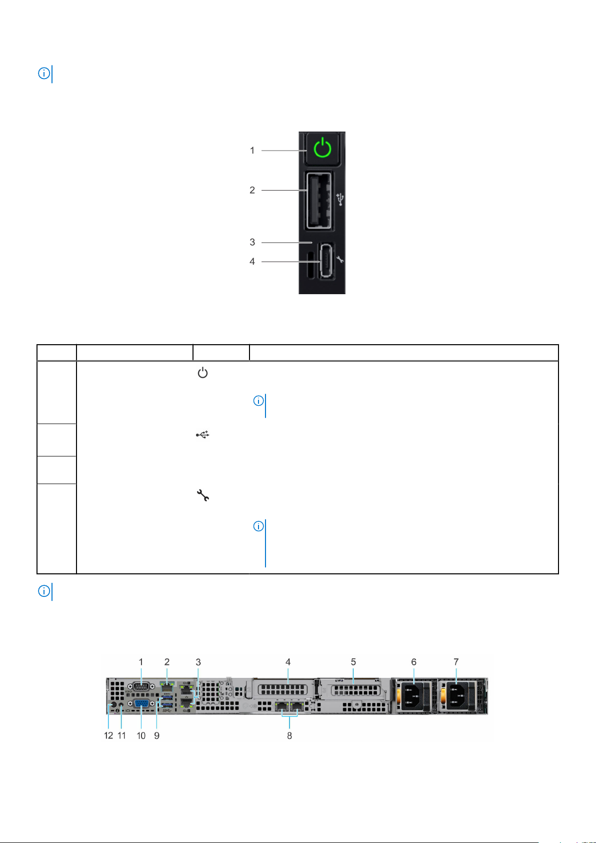
Right control panel view
Figure 6. Right control panel
Table 5. Right control panel
Item Indicator or button Icon Description
1 Power button
2
3
4
USB 2.0-compliant port
iDRAC Direct LED
indicator
iDRAC Direct port (MicroAB USB)
NOTE: For more information on the ports, see the Dell EMC PowerEdge R6515 Technical Specifications.
N/A The iDRAC Direct LED indicator lights up to indicate that the iDRAC Direct
Indicates if the system is powered on or off. Press the power button to
manually power on or off the system.
NOTE: Press the power button to gracefully shut down an ACPI-
compliant operating system.
The USB port is a 4-pin connector and 2.0-compliant. This port enables
you to connect USB devices to the system.
port is actively connected to a device.
The iDRAC Direct port (Micro-AB USB) enables you to access the iDRAC
direct Micro-AB USB features. For more information, see the https://
www.dell.com/idracmanuals.
NOTE: You can configure iDRAC Direct by using a USB to micro USB
(type AB) cable, which you can connect to your laptop or tablet. Cable
length should not exceed 3 feet (0.91 meters). Performance could be
affected by cable quality.
Rear view of the system
Figure 7. Rear view of the system
12
PowerEdge R6515 system overview

Table 6. Rear view of the system
Item Ports, panels, or slots Icon Description
1 Serial port Enables you to connect a serial device to the system.
2 iDRAC dedicated port
3 Ethernet ports (2)
4 PCIe expansion card riser
1A (slot 2)
5 PCIe expansion card riser
2 (slot 3)
6
7
8
9 USB 3.0 port (2) These USB ports support USB 3.0.
10 VGA port Enables you to connect a display device to the system.
Power supply unit (PSU 1) N/A
Power supply unit (PSU2)N/A
LOM Riser Ethernet port
(2) (Optional)
N/A
N/A
N/A The NIC ports that are integrated on the LAN on Motherboard
Enables you to remotely access iDRAC. For more information, see
the iDRAC User’s Guide at www.dell.com/poweredgemanuals.
The Ethernet ports that are integrated on the system board
provide network connectivity. These NIC ports can also be shared
with iDRAC when iDRAC network settings is set to shared mode.
The expansion card riser enables you to connect PCI Express
expansion cards.
The expansion card riser enables you to connect PCI Express
expansion cards.
For information on the PSU configurations, see the Dell EMC
PowerEdge R6515 Technical Specifications on the product
documentation page.
For information on the PSU configurations, see the Dell EMC
PowerEdge R6515 Technical Specifications on the product
documentation page.
(LOM) riser provide network connectivity.
11 System status indicator
cable port
12 System identification
button
For information on the PSU configurations, see the Dell EMC PowerEdge R6515 Technical Specifications on the product
documentation page.
N/A Enables you to connect the status indicator cable and view system
status when the CMA is installed.
Press the system ID button:
● To locate a particular system within a rack.
● To turn the system ID on or off.
To reset iDRAC, press and hold the button for 16 seconds.
NOTE:
● To reset iDRAC using system ID, ensure that the system ID
button is enabled in the iDRAC setup.
● If the system stops responding during POST, press and hold
the system ID button (for more than five seconds) to enter
the BIOS progress mode.
PowerEdge R6515 system overview
13
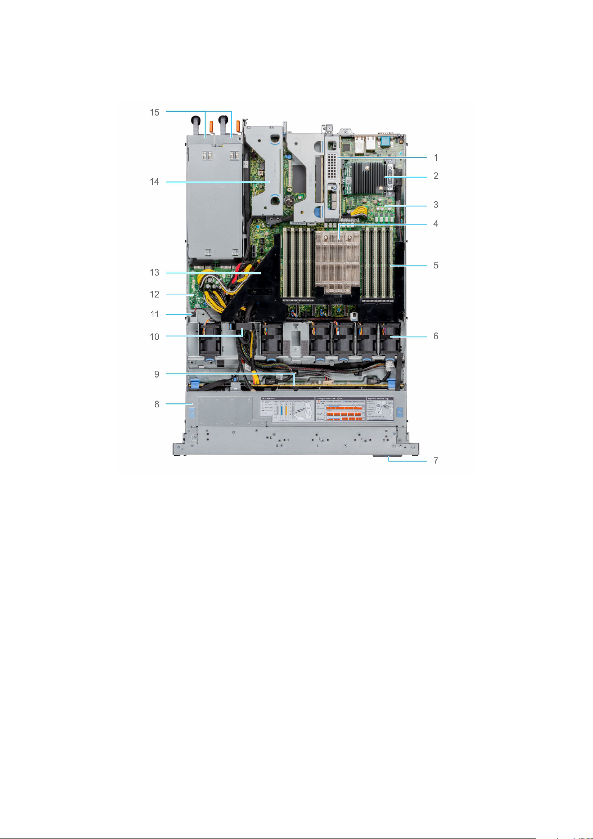
Inside the system
Figure 8. Inside the system
Riser 1A 2. Mini PERC card
1.
3. System board 4. Heat sink
5. Memory module slots 6. Fan
7. Information tag 8. Backplane cover
9. Backplane 10. Cable retention latch
11. Intrusion switch 12. Power interposer board
13. Air shroud 14. Riser 2
15. PSU 1 and PSU 2
Locating the Express Service Code and Service Tag
The unique Express Service Code and Service Tag are used to identify the system.
The information tag is located on the front of the system that includes system information such as Service Tag, Express
Service Code, Manufacture date, NIC, MAC address, QRL label, and so on. If you have opted for the secure default access
to iDRAC, the Information tag also contains the iDRAC secure default password. If you have opted for iDRAC Quick Sync
2, the Information tag also contains the OpenManage Mobile (OMM) label, where administrators can configure, monitor, and
troubleshoot the PowerEdge servers.
14
PowerEdge R6515 system overview
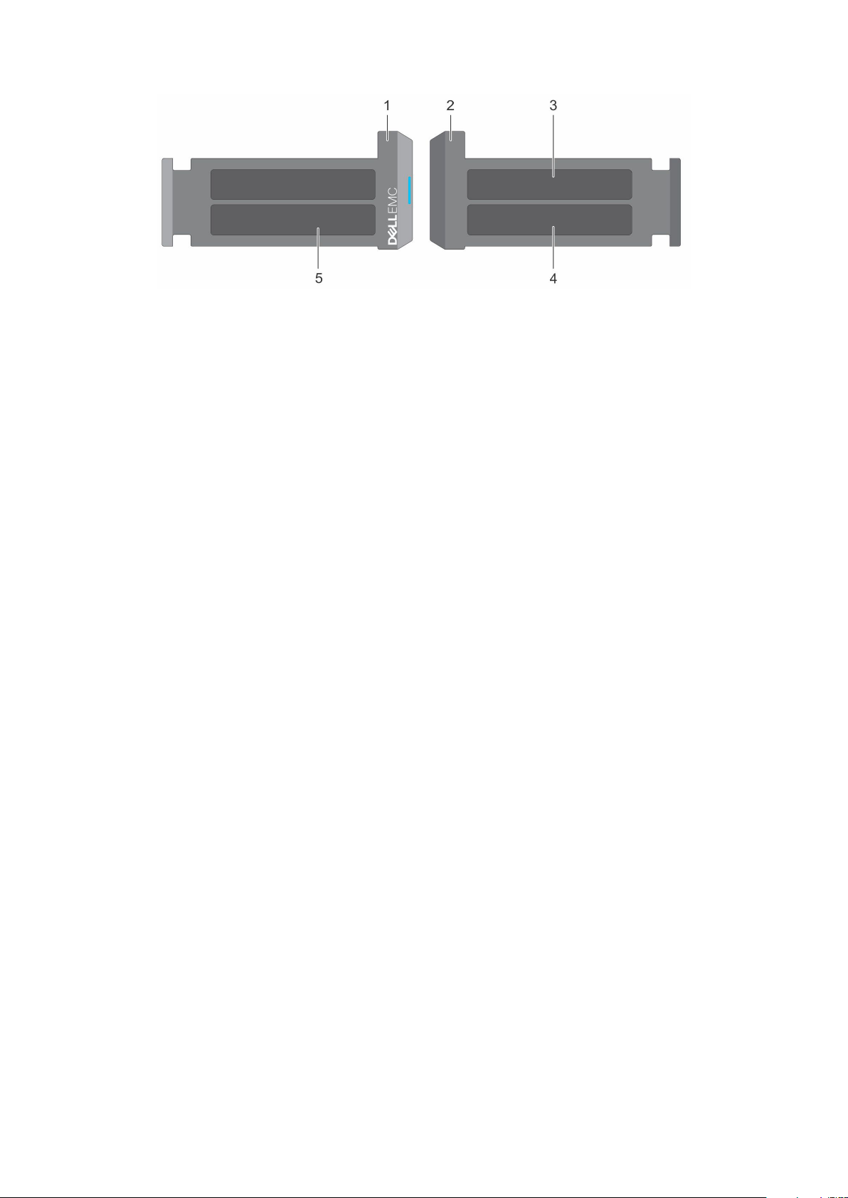
Figure 9. Locating the Express Service Code and Service tag
1. Information tag (front view)
2. Information tag (back view)
3. OpenManage Mobile (OMM) label
4. iDRAC MAC address and iDRAC secure password label
5. Service Tag, Express Service Code, QRL label
The Mini Enterprise Service Tag (MEST) label is located on the rear of the system that includes Service Tag (ST), Express
Service Code (Exp Svc Code), and Manufacture Date (Mfg. Date). The Exp Svc Code is used by Dell EMC to route support calls
to the appropriate personnel.
Alternatively, the Service Tag information is located on a label on left wall of the chassis.
System information label
The system information label is located on back side of the system cover.
PowerEdge R6515 system overview
15
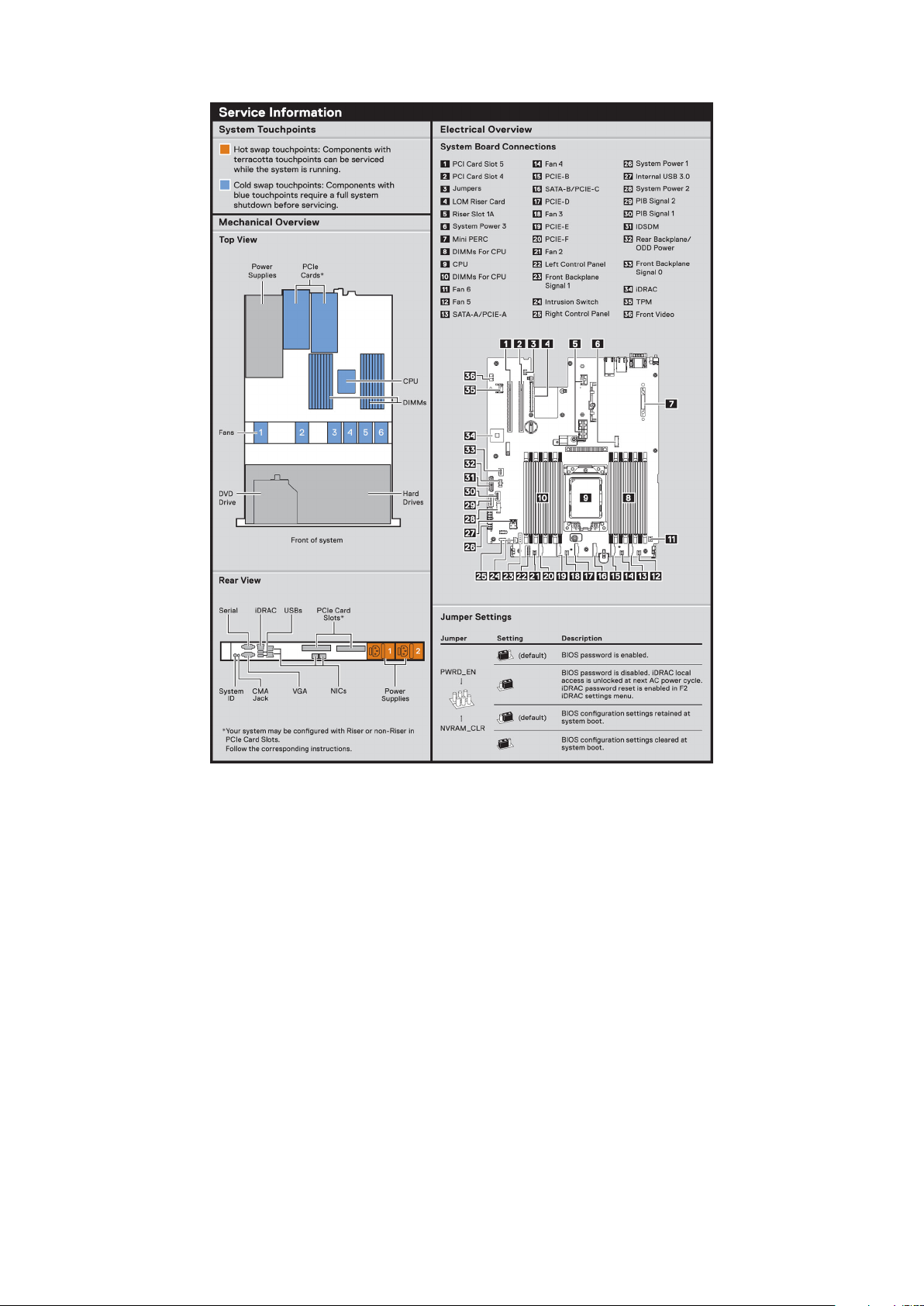
Figure 10. Service information
16
PowerEdge R6515 system overview

Figure 11. Memory information
PowerEdge R6515 system overview
17
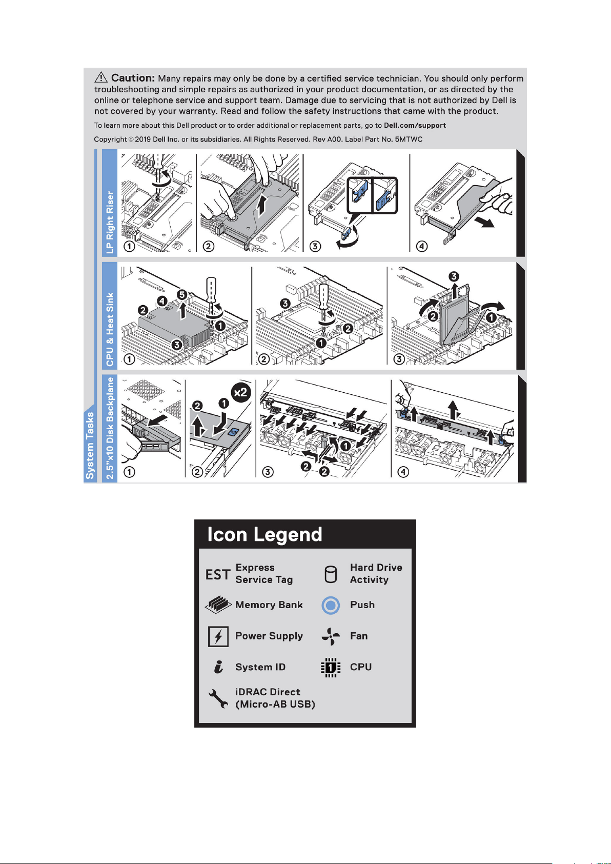
Figure 12. System tasks
Figure 13. Icon Legend
18
PowerEdge R6515 system overview

Figure 14. R6515 QRL
Rail sizing and rack compatibility matrix
For specific information about the rail solutions compatible with your system, see the Dell EMC Enterprise Systems
Rail Sizing and Rack Compatibility Matrix available at https://i.dell.com/sites/csdocuments/Business_solutions_engineering-
Docs_Documents/en/rail-rack-matrix.pdf.
The document provides the information that is listed below:
● Specific details about rail types and their functionalities
● Rail adjustability ranges for various rack mounting flange types
● Rail depth with and without cable management accessories
● Rack types that are supported for various rack mounting flange types
PowerEdge R6515 system overview
19

Initial system setup and configuration
This section describes the tasks for initial setup and configuration of the Dell EMC system. The sections provide general steps
that you must complete to set up the system and the reference guides for detailed information.
Topics:
• Setting up the system
• iDRAC configuration
• Resources to install operating system
Setting up the system
Perform the following steps to set up the system:
Steps
1. Unpack the system.
2. Install the system into the rack. For more information see the rail installation and cable management accessory guides
relevant to your rail and cable management solution at www.dell.com/poweredgemanuals.
3. Connect the peripherals to the system and the system to the electrical outlet.
4. Power on the system by pressing the power button.
For more information about setting up the system, see the Getting Started Guide that is shipped with your system.
For information on how to manage basic settings and features of the system, see the Dell EMC PowerEdge R6515 BIOS and
UEFI Reference Guide on the product documentation page.
3
iDRAC configuration
The Integrated Dell Remote Access Controller (iDRAC) is designed to make you more productive as a system administrator
and improve the overall availability of Dell EMC servers. iDRAC alerts you to system issues, helps you to perform remote
management, and reduces the need for physical access to the system.
Options to set up iDRAC IP address
To enable communication between your system and iDRAC, you must first configure the network settings based on your
network infrastructure. The network settings option is set to DHCP, by default.
NOTE: For static IP configuration, you must request for the setting at the time of purchase.
You can set up the iDRAC IP address using one of the following interfaces. For information about how to set up iDRAC IP
address, see the documentation links provided in the table.
Table 7. Interfaces to set up iDRAC IP address
Interface Documentation links
iDRAC Settings utility Integrated Dell Remote Access Controller User's Guide at
https://www.dell.com/idracmanuals or for system specific
Integrated Dell Remote Access Controller User's Guide,
go to https://www.dell.com/poweredgemanuals > Product
Support page of your system > Manuals & documents.
NOTE: To determine the most recent iDRAC release
for your platform and for latest documentation version,
20 Initial system setup and configuration
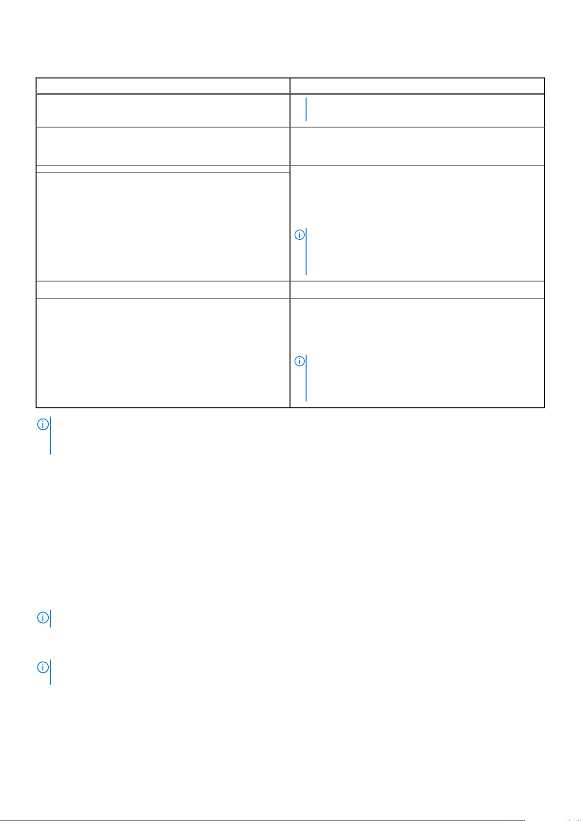
Table 7. Interfaces to set up iDRAC IP address (continued)
Interface Documentation links
see KB article https://www.dell.com/support/article/
sln308699.
OpenManage Deployment Toolkit OpenManage Deployment Toolkit User's Guide available at
https://www.dell.com/openmanagemanuals > Open Manage
Deployment Toolkit.
Lifecycle Controller
Server LCD panel LCD panel section.
iDRAC Direct and Quick Sync 2 (optional) Integrated Dell Remote Access Controller User's Guide at
NOTE: To access iDRAC, ensure that you connect the ethernet cable to the iDRAC9 dedicated network port or use iDRAC
Direct port by using the USB cable. You can also access iDRAC through the shared LOM mode, if you have opted for a
system that has the shared LOM mode enabled.
Lifecycle Controller User’s Guide at https://www.dell.com/
idracmanuals or for system specific Lifecycle Controller
User’s Guide, go to https://www.dell.com/poweredgemanuals
> Product Support page of your system > Manuals &
documents.
NOTE: To determine the most recent iDRAC release
for your platform and for latest documentation version,
see KB article https://www.dell.com/support/article/
sln308699.
https://www.dell.com/idracmanuals or for system specific
Integrated Dell Remote Access Controller User's Guide,
go to https://www.dell.com/poweredgemanuals > Product
Support page of your system > Manuals & documents.
NOTE: To determine the most recent iDRAC release
for your platform and for latest documentation version,
see KB article https://www.dell.com/support/article/
sln308699.
Options to log in to iDRAC
To log in to the iDRAC Web User Interface, open a browser and enter the IP address.
You can log in to iDRAC as:
● iDRAC user
● Microsoft Active Directory user
● Lightweight Directory Access Protocol (LDAP) user
In the log in screen displayed, if you have opted for secure default access to iDRAC, enter the iDRAC secure default password
available on back side of the Information Tag. If you have not opted for secure default access to iDRAC, enter the default user
name and password – r oot and c alv in. You can also log in by using your Single Sign-On or Smart Card.
NOTE: Ensure that you change the default username and password after setting up the iDRAC IP address.
For more information about logging in to the iDRAC and iDRAC licenses, see the latest Integrated Dell Remote Access Controller
User's Guide at www.dell.com/idracmanuals.
To determine the most recent iDRAC release for your platform and for latest documentation version, see KB article
NOTE:
https://www.dell.com/support/article/sln308699.
You can also access iDRAC using command-line protocol - RACADM. For more information, see the iDRAC with Lifecycle
Controller RACADM CLI Guide available at www.dell.com/idracmanuals.
You can also access iDRAC using automation tool - Redfish API. For more information, see the iDRAC9 with Lifecycle Controller
Redfish API Guide available at https://www.dell.com/idracmanuals.
Initial system setup and configuration
21
Resources to install operating system
If the system is shipped without an operating system, you can install a supported operating system by using one of the
resources provided in the table. For information about how to install the operating system, see the documentation links provided
in the table.
Table 8. Resources to install the operating system
Resource Documentation links
iDRAC Integrated Dell Remote Access Controller User's Guide at https://www.dell.com/idracmanuals or for
system specific Integrated Dell Remote Access Controller User's Guide, go to https://www.dell.com/
poweredgemanuals > Product Support page of your system > Manuals & documents.
NOTE: To determine the most recent iDRAC release for your platform and for latest
documentation version, see KB article at https://www.dell.com/support/article/sln308699.
Lifecycle Controller Lifecycle Controller User’s Guide at https://www.dell.com/idracmanuals or for system specific
Lifecycle Controller User’s Guide, go to https://www.dell.com/poweredgemanuals > Product
Support page of your system > Manuals & documents. Dell recommends using Lifecycle Controller
to install the OS, since all required drivers are installed to the system.
NOTE: To determine the most recent iDRAC release for your platform and for latest
documentation version, see KB article at https://www.dell.com/support/article/sln308699.
OpenManage
Deployment Toolkit
Dell certified VMware
ESXi
NOTE: For more information about Installation and How-to videos for supported operating systems on PowerEdge system
see, Supported Operating Systems for Dell EMC PowerEdge systems.
www.dell.com/openmanagemanuals > OpenManage Deployment Toolkit
www.dell.com/virtualizationsolutions
Options to download firmware
You can download firmware from the Dell support site. For information, see the Downloading drivers and firmware section.
You can also choose any one of the following options to download the firmware. For information about how to download the
firmware, see the documentation links provided in the table.
Table 9. Options to download firmware
Option Documentation link
Using Dell Remote Access Controller Lifecycle Controller
(iDRAC with LC)
Using Dell Repository Manager (DRM) www.dell.com/openmanagemanuals > Repository Manager
Using Dell Server Update Utility (SUU) www.dell.com/openmanagemanuals > Server Update Utility
Using Dell OpenManage Deployment Toolkit (DTK) www.dell.com/openmanagemanuals > OpenManage
www.dell.com/idracmanuals
Deployment Toolkit
Using iDRAC virtual media www.dell.com/idracmanuals
Options to download and install OS drivers
You can choose any one of the following options to download and install OS drivers. For information about how to download or
install OS drivers, see the documentation links provided in the table.
Table 10. Options to download and install OS drivers
22 Initial system setup and configuration

Table 10. Options to download and install OS drivers
Option Documentation
Dell EMC support site Downloading drivers and firmware section.
iDRAC virtual media Integrated Dell Remote Access Controller User's Guide at
https://www.dell.com/idracmanuals or for system specific
Integrated Dell Remote Access Controller User's Guide,
go to https://www.dell.com/poweredgemanuals > Product
Support page of your system > Manuals & documents.
NOTE: To determine the most recent iDRAC release for
your platform and for latest documentation version, see
https://www.dell.com/support/article/sln308699.
Downloading drivers and firmware
It is recommended that you download and install the latest BIOS, drivers, and systems management firmware on the system.
Prerequisites
Ensure that you clear the web browser cache before downloading the drivers and firmware.
Steps
1. Go to www.dell.com/support/drivers.
2. Enter the Service Tag of the system in the Enter a Dell Service Tag, Dell EMC Product ID or Model field, and then press
Enter.
NOTE:
If you do not have the Service Tag, select Detect PC to automatically detect the Service Tag, or click Browse
all products, and navigate to your product.
3. On the displayed product page, click Drivers & Downloads.
On the Drivers & Downloads page, all drivers that are applicable to the system are displayed.
4. Download the drivers to a USB drive, CD, DVD or local machine.
Initial system setup and configuration
23

Installing and removing system components
Topics:
• Safety instructions
Before working inside your system
•
• After working inside your system
• Recommended tools
• Optional front bezel
• System cover
• Drive backplane cover
• Air shroud
• Cooling fan
• Intrusion switch module
• Drives
• Drive backplane
• Cable routing
• System memory
• Processor and heat sink
• Expansion cards and expansion card risers
• Micro SD card
• M.2 SSD module
• Optional IDSDM module
• LOM riser card
• Mini PERC card
• System battery
• Optional internal USB memory key
• VGA module
• Optional optical drive
• Power supply unit
• Power interposer board
• System board
• Trusted Platform Module
• Control panel
4
Safety instructions
NOTE: To avoid injury, do not lift the system on your own. Get others to assist you.
WARNING: Opening or removing the system cover while the system is turned on may expose you to a risk of
electric shock..
CAUTION: Many repairs may only be done by a certified service technician. You should only perform
troubleshooting and simple repairs as authorized in your product documentation, or as directed by the online or
telephone service and support team. Damage due to servicing that is not authorized by Dell is not covered by
your warranty. Read and follow the safety instructions that are shipped with your product.
CAUTION: To ensure proper operation and cooling, all system bays and fans must be always populated with a
component or a blank.
24 Installing and removing system components

NOTE: It is recommended that you always use an antistatic mat and antistatic strap while working on components inside
the system.
NOTE: While replacing the hot swappable PSU, after next server boot; the new PSU automatically updates to the same
firmware and configuration of the replaced one. For more information about the Part replacement configuration, see the
Lifecycle Controller User's Guide at https://www.dell.com/idracmanuals
NOTE: While replacing faulty storage controller/FC/NIC card with the same type of card, after you power on the system;
the new card automatically updates to the same firmware and configuration of the faulty one. For more information about
the Part replacement configuration, see the Lifecycle Controller User's Guide at https://www.dell.com/idracmanuals
Before working inside your system
Prerequisites
Follow the safety guidelines listed in Safety instructions.
Steps
1. Power off the system and all attached peripherals.
2. Disconnect the system from the electrical outlet, and disconnect the peripherals.
3. If applicable, remove the system from the rack.
For more information, see the Rail Installation Guide relevant to your rail solutions at www.dell.com/poweredgemanuals.
4. Remove the system cover.
After working inside your system
Prerequisites
Follow the safety guidelines listed in Safety instructions.
Steps
1. Replace the system cover.
2. If applicable, install the system into the rack.
For more information, see the Rail Installation Guide relevant to your rail solutions at www.dell.com/poweredgemanuals.
3. Reconnect the peripherals and connect the system to the electrical outlet, and then power on the system.
Recommended tools
You need the following tools to perform the removal and installation procedures:
● Key to the bezel lock. The key is required only if your system includes a bezel.
● Phillips #1 screwdriver
● Phillips #2 screwdriver
● Torx #T20 screwdriver
● 5mm hex nut screwdriver
● Plastic scribe
● 1/4 inch flat blade screwdriver
● Wrist grounding strap connected to the ground
● ESD mat
Installing and removing system components
25
Optional front bezel
NOTE: LCD panel is optional on the front bezel. If the front bezel has an LCD panel, see LCD panel section.
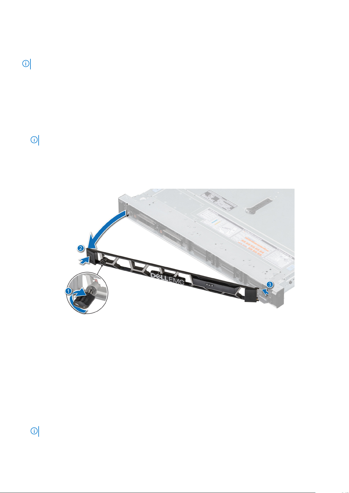
Removing the front bezel
The procedure to remove the front bezel with and without the LCD panel is the same.
Prerequisites
1. Follow the safety guidelines listed in the Safety instructions.
2. Keep the bezel key handy.
NOTE: The bezel key is part of the LCD bezel package.
Steps
1. Unlock the bezel.
2. Press the release button, and disengage the left end of the bezel.
3. Unhook the right end, and remove the bezel.
Figure 15. Removing the front bezel with the LCD panel
Next steps
Replace the bezel.
Installing the front bezel
The procedure to install the front bezel with and without the LCD panel is the same.
Prerequisites
1. Follow the safety guidelines listed in the Safety instructions.
2. Locate and remove the bezel key.
NOTE: The bezel key is part of the LCD bezel package.
26 Installing and removing system components
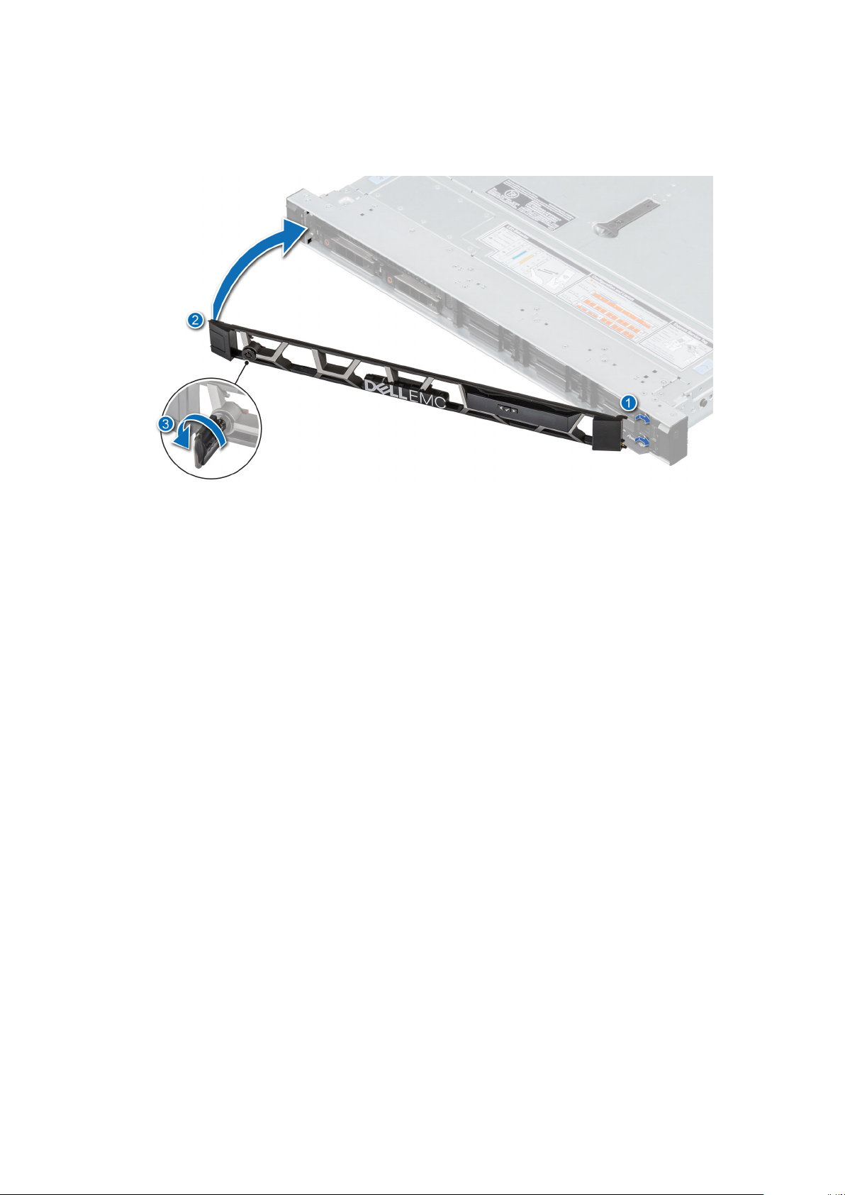
Steps
1. Align and insert the tabs on the bezel into the slots on the system.
2. Press the bezel until the release button clicks in place.
3. Lock the bezel.
Figure 16. Installing the front bezel with the LCD panel
System cover
Removing the system cover
Prerequisites
1. Follow the safety guidelines listed in the Safety instructions.
2. Power off the system, and any attached peripherals.
3. Disconnect the system from the electrical outlet and peripherals.
Steps
1. Use a 1/4 inch flat head or a Phillips #2 screwdriver to rotate the lock counterclockwise to the unlock position.
2. Lift the release latch until the system cover slides back.
3. Lift the cover from the system.
Installing and removing system components
27

Figure 17. Removing the system cover
Next steps
Replace the system cover.
Installing the system cover
Prerequisites
1. Follow the safety guidelines listed in the Safety instructions.
2. Follow the procedure listed in Before working inside your system.
3. Ensure that all internal cables are connected and routed properly, and no tools or extra parts are left inside the system.
Steps
1. Align the tabs on the system cover with the guide slots on the system.
2. Close the system cover release latch.
3. Using a 1/4 inch flat head or Phillips #2 screwdriver, rotate the lock clockwise to the lock position.
28
Installing and removing system components
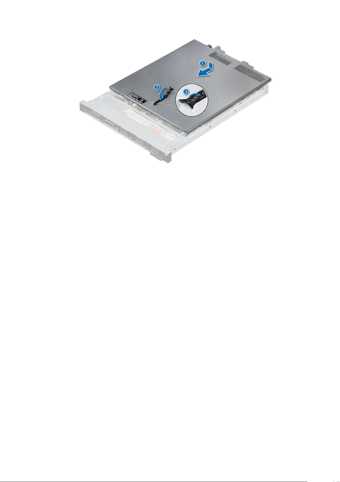
Figure 18. Installing the system cover
Next steps
Follow the procedure listed in After working inside your system.
Drive backplane cover
Removing the drive backplane cover
Prerequisites
1. Follow the safety guidelines listed in the Safety instructions.
2. Follow the procedure listed in the Before working inside your system.
Steps
1. Slide the backplane cover in the direction of the arrows marked on the backplane cover.
2. Lift the backplane cover from the system.
Installing and removing system components
29

Figure 19. Removing the drive backplane cover
Next steps
Replace the backplane cover.
Installing the drive backplane cover
Prerequisites
Follow the safety guidelines listed in the Safety instructions.
Steps
1. Align the backplane cover with the guide slots on the system.
2. Slide the backplane cover toward the front of the system until the backplane cover fits into place.
30
Installing and removing system components
 Loading...