

Dell R510 User Manual

Dell™ PowerEdge™
R510 Systems
Hardware Owner’s
Manual
Regulatory Model E12S Series and E13S Series
Regulatory Type E12S001 and E13S001

Notes, Cautions, and Warnings
NOTE: A NOTE indicates important information that helps you make better use of
your computer.
CAUTION: A CAUTION indicates potential damage to hardware or loss of data if
instructions are not followed.
WARNING: A WARNING indicates a potential for property damage,
personal injury, or death.
____________________
Information in this document is subject to change without notice.
© 2009 Dell Inc. All rights reserved.
Reproduction of these materials in any manner whatsoever without the written permission of Dell Inc.
is strictly forbidden.
Trademarks used in this text: Dell, the DELL logo, and PowerEdge are trademarks of Dell Inc.;
Microsoft, Windows, W indows Server, and MS-DOS are either trademarks or re gistered trademarks of
Microsoft Corporation in the United States and/or other countries.
Other trademarks and trade names may be used in this document to refer to either the entities claiming
the marks and names or their products. Dell Inc. disclaims any proprietary interest in trademarks and
trade names other than its own.
Regulatory Model E12S Series and E13S Series
Regulatory Type E12S001 and E13S001
November 2009 Rev. A00

Contents
1 About Your System . . . . . . . . . . . . . . . . . . 13
Accessing System Features During Startup. . . . . . . 13
Front-Panel Features and Indicators
LCD Panel Features (Optional)
Home Screen
Setup Menu
View Menu
. . . . . . . . . . . . . . . . . . . . 19
. . . . . . . . . . . . . . . . . . . . . 20
. . . . . . . . . . . . . . . . . . . . . 20
Hard-Drive Indicator Patterns
Back-Panel Features and Indicators
. . . . . . . . . . 14
. . . . . . . . . . . . . . 18
. . . . . . . . . . . . . . 21
. . . . . . . . . . 22
Guidelines for Connecting Optional External
Devices
NIC Indicator Codes
Power Indicator Codes
Diagnostic Lights (Optional)
LCD Status Messages (Optional)
. . . . . . . . . . . . . . . . . . . . . . . . . 25
. . . . . . . . . . . . . . . . . . . 25
. . . . . . . . . . . . . . . . . 26
. . . . . . . . . . . . . . . 27
. . . . . . . . . . . . 29
Solving Problems Described by LCD
Status Messages
Removing LCD Status Messages
. . . . . . . . . . . . . . . . . . 41
. . . . . . . . . . 41
System Messages
Warning Messages
. . . . . . . . . . . . . . . . . . . . 42
. . . . . . . . . . . . . . . . . . . 59
Contents 3

Diagnostics Messages. . . . . . . . . . . . . . . . . . 59
Alert Messages
Other Information You May Need
. . . . . . . . . . . . . . . . . . . . . 59
. . . . . . . . . . . . 60
2 Using the System Setup Program and
UEFI Boot Manager
Choosing the System Boot Mode . . . . . . . . . . . . 61
Entering the System Setup Program
Responding to Error Messages
Using the System Setup Program
Navigation Keys
System Setup Options
Main Screen. . . . . . . . . . . . . . . . . . . . . . . . . . . . . . . . . . .
Memory Settings Screen
Processor Settings Screen
SATA Settings Screen (Optional)
Boot Settings Screen
Integrated Devices Screen
PCI IRQ Assignments Screen
Serial Communication Screen
Embedded Server Management Screen
Power Management Screen
System Security Screen
Exit Screen
. . . . . . . . . . . . . . . . . 61
. . . . . . . . . . . 62
. . . . . . . . . . . 62
. . . . . . . . . . . . . . . . . . . 62
. . . . . . . . . . . . . . . . . . 63
. . . . . . . . . . . . . . 65
. . . . . . . . . . . . . 66
. . . . . . . . . . 67
. . . . . . . . . . . . . . . . 67
. . . . . . . . . . . . . 68
. . . . . . . . . . . . 69
. . . . . . . . . . . 69
. . . . . . 70
. . . . . . . . . . . . 71
. . . . . . . . . . . . . . 71
. . . . . . . . . . . . . . . . . . . . . 73
63
4 Contents
Entering the UEFI Boot Manager
. . . . . . . . . . . . . 74
Using the UEFI Boot Manager Navigation Keys
UEFI Boot Manager Screen
UEFI Boot Settings Screen
System Utilities Screen
. . . . . . . . . . . . . 75
. . . . . . . . . . . . . 75
. . . . . . . . . . . . . . . 75
. . 74

System and Setup Password Features . . . . . . . . . 76
Using the System Password
Using the Setup Password
. . . . . . . . . . . . 76
. . . . . . . . . . . . . 78
Embedded System Management
Baseboard Management Controller Configuration
Entering the BMC Setup Module
iDRAC Configuration Utility
Entering the iDRAC Configuration Utility
. . . . . . . . . . . . 79
. . . 80
. . . . . . . . . . 81
. . . . . . . . . . . . . . . 81
. . . . . . 81
3 Installing System Components . . . . . . . . 83
Recommended Tools. . . . . . . . . . . . . . . . . . . 83
Inside the System
Front Bezel (Optional)
Removing the Front Bezel
Installing the Front Bezel
Opening and Closing the System
Opening the System
Closing the System
Cooling Shroud
Removing the Cooling Shroud
Installing the Cooling Shroud
. . . . . . . . . . . . . . . . . . . . 83
. . . . . . . . . . . . . . . . . . 86
. . . . . . . . . . . . . 86
. . . . . . . . . . . . . . 87
. . . . . . . . . . . . 87
. . . . . . . . . . . . . . . . 87
. . . . . . . . . . . . . . . . . 89
. . . . . . . . . . . . . . . . . . . . . . 90
. . . . . . . . . . . 90
. . . . . . . . . . . . 91
Hard Drives
. . . . . . . . . . . . . . . . . . . . . . . . 91
Removing a Hard-Drive Blank
Installing a Hard-Drive Blank
Removing a Hot-Swap Hard Drive
Installing a Hot-Swap Hard Drive
. . . . . . . . . . . 91
. . . . . . . . . . . . 92
. . . . . . . . . 92
. . . . . . . . . 93
Contents 5

Removing a Hard Drive From a
Hard-Drive Carrier
. . . . . . . . . . . . . . . . . 94
Installing a Hard Drive Into a
Hard-Drive Carrier
. . . . . . . . . . . . . . . . . 95
Removing a Cabled Hard Drive
Installing a Cabled Hard Drive
Removing a Hard Drive From a
Hard-Drive Carrier
. . . . . . . . . . . . . . . . . 98
Installing a Hard Drive Into a
Hard-Drive Carrier
. . . . . . . . . . . . . . . . . 98
. . . . . . . . . . . 95
. . . . . . . . . . . 96
Internal Hard Drives
. . . . . . . . . . . . . . . . . . . 99
Removing an Internal Hard Drive Bay
Installing an Internal Hard Drive Bay
Removing an Internal Hard Drive From the
Internal Hard-Drive Bay
. . . . . . . . . . . . . . 101
Installing a Hard Drive Into a
Hard-Drive Bay
Optical Drive (Optional)
Removing an Optical Drive
Installing an Optical Drive
Cooling Fans
Removing a Cooling Fan
Replacing a Cooling Fan
Power Supplies
. . . . . . . . . . . . . . . . . . 102
. . . . . . . . . . . . . . . . 103
. . . . . . . . . . . . 103
. . . . . . . . . . . . 104
. . . . . . . . . . . . . . . . . . . . . . 105
. . . . . . . . . . . . . 105
. . . . . . . . . . . . . 109
. . . . . . . . . . . . . . . . . . . . 109
Removing a Redundant Power Supply
Installing a Redundant Power Supply
Removing the Power Supply Blank
Installing the Power Supply Blank
Removing a Non-Redundant Power Supply
Installing a Non-Redundant Power Supply
. . . . . . . 99
. . . . . . . 101
. . . . . . 110
. . . . . . 111
. . . . . . . . 112
. . . . . . . . 112
. . . 112
. . . . 114
6 Contents

System Memory . . . . . . . . . . . . . . . . . . . . . 114
General Memory Module Installation
Guidelines
Mode-Specific Guidelines
Installing Memory Modules
Removing Memory Modules
. . . . . . . . . . . . . . . . . . . . . 115
. . . . . . . . . . . . . 116
. . . . . . . . . . . . 119
. . . . . . . . . . . . 121
Expansion Cards and Expansion-Card Risers
Expansion Card Installation Guidelines
Installing an Expansion Card
Removing an Expansion Card
. . . . . . . . . . . . 124
. . . . . . . . . . . 126
Removing an Expansion-Card Riser
Installing an Expansion-Card Riser
Integrated Storage Controller Card
. . . . . . . . . . . 129
Removing the Storage Controller Card
Installing the Storage Controller Card
iDRAC6 Express Card (Optional)
. . . . . . . . . . . . . 132
Installing an iDRAC6 Express Card
Removing an iDRAC6 Express Card
iDRAC6 Enterprise Card (Optional)
. . . . . . . . . . . 134
Installing an iDRAC6 Enterprise Card
Removing an iDRAC6 Enterprise Card
. . . . . . 122
. . . . . . 122
. . . . . . . . 127
. . . . . . . . . 128
. . . . . . . 129
. . . . . . . 131
. . . . . . . . . 132
. . . . . . . . 133
. . . . . . . 134
. . . . . . . 136
VFlash Media (Optional) . . . . . . . . . . . . . . . . . 137
Installing a VFlash Media Card
Removing a VFlash Media Card
. . . . . . . . . . . 137
. . . . . . . . . . 137
Internal USB Memory Key
Processors
. . . . . . . . . . . . . . . . . . . . . . . . 138
Removing a Processor
Installing a Processor
. . . . . . . . . . . . . . . 137
. . . . . . . . . . . . . . . 138
. . . . . . . . . . . . . . . 142
Contents 7

System Battery . . . . . . . . . . . . . . . . . . . . . 143
Replacing the System Battery
. . . . . . . . . . 143
RAID Battery (Optional)
Removing the RAID Battery
Installing the RAID Battery
. . . . . . . . . . . . . . . . 146
. . . . . . . . . . . . 146
. . . . . . . . . . . . 147
Control Panel Assembly—LED (Optional)
Removing the Control Panel Assembly
(Four–Hard-Drive System)
. . . . . . . . . . . . 147
Installing the Control Panel Assembly
(Four–Hard-Drive System)
. . . . . . . . . . . . 149
Removing the Control-Panel Module–LED
(Twelve–Hard-Drive System)
. . . . . . . . . . . 149
Installing the Control-Panel Module–LED
(Twelve–Hard-Drive System)
. . . . . . . . . . . 151
Control Panel Assembly—LCD (Optional)
Removing the Control Panel Display Module
Installing the Control Panel Display Module
Removing the Control Panel Assembly
Installing the Control Panel Assembly
Front-Panel IO Module (Optional)
. . . . . . . . . . . 154
Removing the Front-Panel IO Module
(Twelve–Hard-Drive System)
. . . . . . . . . . . 154
Installing the Front-Panel IO Module
(Twelve–Hard-Drive System)
. . . . . . . . . . . 156
. . . . . . . 147
. . . . . . . 151
. . . 151
. . . 152
. . . . . . 152
. . . . . . 154
8 Contents
SAS Backplane
. . . . . . . . . . . . . . . . . . . . . 156
Removing the SAS Backplane
Installing the SAS Backplane
Power Distribution Board
. . . . . . . . . . . . . . . 161
Removing the Power Distribution Board
Replacing the Power Distribution Board
. . . . . . . . . . 156
. . . . . . . . . . . 160
. . . . . 161
. . . . . 164

System Board . . . . . . . . . . . . . . . . . . . . . . 165
Removing the System Board
Installing the System Board
. . . . . . . . . . . . 165
. . . . . . . . . . . . 167
4 Troubleshooting Your System . . . . . . . . 169
Safety First—For You and Your System . . . . . . . . . 169
Troubleshooting System Startup Failure
Troubleshooting External Connections
Troubleshooting the Video Subsystem
Troubleshooting a USB Device
Troubleshooting a Serial I/O Device
Troubleshooting a NIC
. . . . . . . . . . . . . . . . . . 171
Troubleshooting a Wet System
Troubleshooting a Damaged System
Troubleshooting the System Battery
Troubleshooting Power Supplies
. . . . . . . . . 169
. . . . . . . . . 170
. . . . . . . . . . . . . 170
. . . . . . . . . . 171
. . . . . . . . . . . . . 172
. . . . . . . . . . 174
. . . . . . . . . . . 174
. . . . . . . . . . . . 175
Troubleshooting System Cooling Problems
Troubleshooting a Fan
Troubleshooting System Memory
Troubleshooting an Internal USB Key
. . . . . . . . . . . . . . . . . . 176
. . . . . . . . . . . . 177
. . . . . . . . . . 179
. . . . . . . . 169
. . . . . . . 176
Troubleshooting an Optical Drive
Troubleshooting a Hard Drive
. . . . . . . . . . . . . . 181
. . . . . . . . . . . . 180
Contents 9

Troubleshooting an Internal Hard Drive . . . . . . . . 182
Troubleshooting a Storage Controller
Troubleshooting Expansion Cards
Troubleshooting Processors
. . . . . . . . . . . . . . 186
. . . . . . . . . 183
. . . . . . . . . . . 184
5 Running the System Diagnostics . . . . . . 189
Using Online Diagnostics . . . . . . . . . . . . . . . 189
Embedded System Diagnostics Features
When to Use the Embedded System Diagnostics
Running the Embedded System Diagnostics
Embedded System Diagnostics Testing Options
Using the Custom Test Options
. . . . . . . . . . . . 191
Selecting Devices for Testing
Selecting Diagnostics Options
Viewing Information and Results
. . . . . . . 189
. . . 190
. . . . . 190
. . . 191
. . . . . . . . . . . 191
. . . . . . . . . . 191
. . . . . . . . . 192
6 Jumpers and Connectors. . . . . . . . . . . . 193
10 Contents
System Board Jumpers. . . . . . . . . . . . . . . . . 193
System Board Connectors
Disabling a Forgotten Password
. . . . . . . . . . . . . . . 194
. . . . . . . . . . . . 196

7 Getting Help. . . . . . . . . . . . . . . . . . . . . . 199
Contacting Dell . . . . . . . . . . . . . . . . . . . . . 199
Glossary . . . . . . . . . . . . . . . . . . . . . . . . . . . . 201
Index
. . . . . . . . . . . . . . . . . . . . . . . . . . . . . . 211
Contents 11

12 Contents

About Your System
NOTE: The illustrations in this document show systems with hot-swappable
hard drives.
Accessing System Features During Startup
The following keystrokes provide access to system features during startup.
Keystroke Description
<F2> Enters the System Setup program. See "Using the System Setup
Program and UEFI Boot Manager" on page 61.
<F10> Enters System Services, which opens the Lifecycle Controller.
The controller allows you to access utilities such as embedded system
diagnostics. For information on Lifecycle Controller or any of the
Lifecycle Controller software components, see the Lifecycle
Controller documentation on the Dell Support website at
support.dell.com/manuals.
<F11> Enters the BIOS Boot Manager or the Unified Extensible Firmware
Interface (UEFI) Boot Manager, depending on the system’s boot
configuration. See "Using the System Setup Program and
UEFI Boot Manager" on page 61.
<F12> Starts Preboot eXecution Environment (PXE) boot.
<Ctrl><E> Enters the Baseboard Management Controller (BMC) or iDRAC
Configuration Utility, which allows access to the system event log
(SEL) and configuration of remote access to the system. For more
information, see the BMC or iDRAC user documentation.
<Ctrl><C> Enters the SAS Configuration Utility. For more information, see the
SAS adapter documentation.
<Ctrl><R> Enters the RAID configuration utility. For more information, see the
documentation for your SAS RAID card.
<Ctrl><S> Enters the utility to configure NIC settings for PXE boot. For more
information, see the documentation for your integrated NIC.
About Your System 13
Front-Panel Features and Indicators
1
4
5
7
6
3
2
89
10
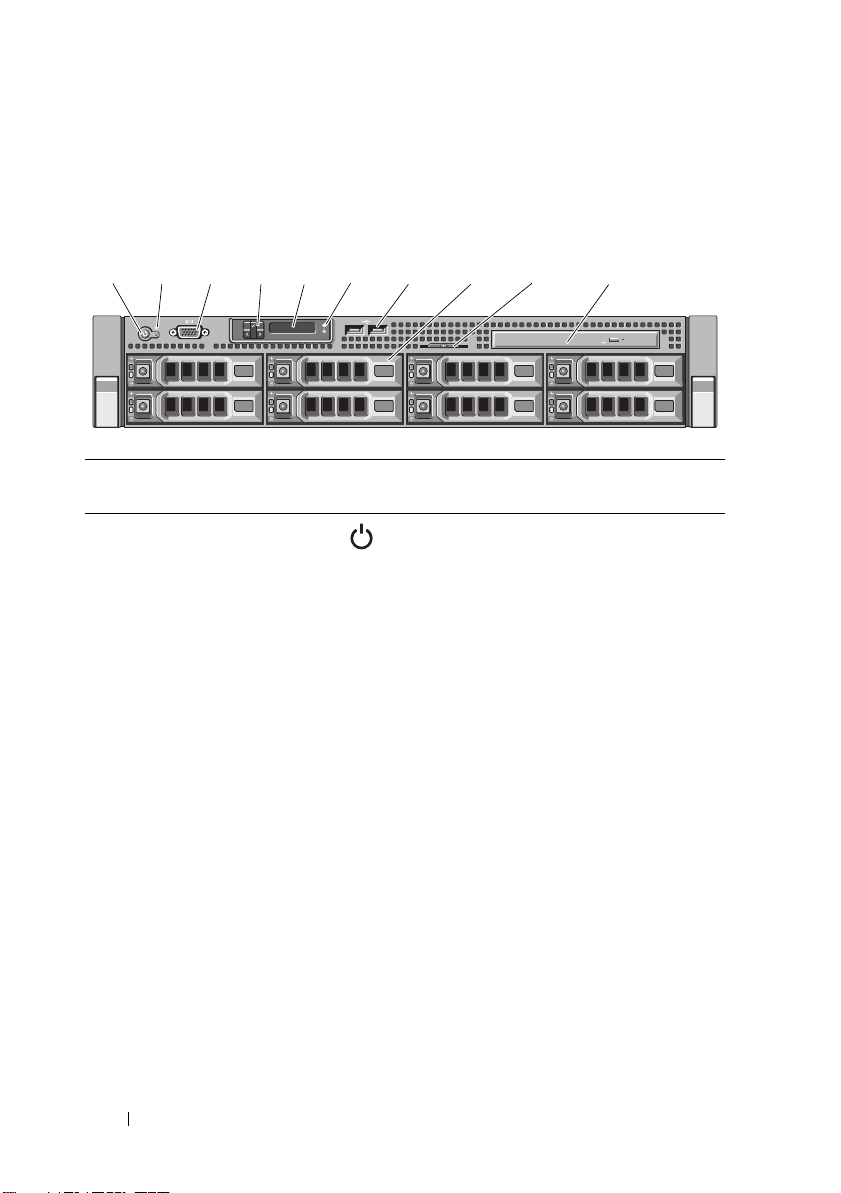
Figure 1-1. Front-Panel Features and Indicators (Eight–Hard-Drive System)
Item Indicator, Button,
or Connector
1 Power-on indicator/
power button
Icon Description
The power-on indicator lights
when the system power is on.
The power button controls the
DC power supply output to the system.
When the optional system bezel is
installed, the power button is not
accessible.
NOTE: When powering on the system,
the video monitor can take from several
seconds to over 2 minutes to display an
image, depending on the amount of
memory installed in the system.
NOTE: On ACPI-compliant operating
systems, turning off the system using the
power button causes the system to
perform a graceful shutdown before
power to the system is turned off.
NOTE: To force an ungraceful shutdown,
press and hold the power button for
5 seconds.
14 About Your System

Item Indicator, Button,
or Connector
2 NMI button Used to troubleshoot software and
3 Video connector Connects a monitor to the system.
4 LCD menu buttons
(optional)
5 LCD panel (optional) Provides system ID, status information,
Icon Description
device driver errors when using certain
operating systems. This button can be
pressed using the end of a paper clip.
Use this button only if directed to do so
by qualified support personnel or by the
operating system's documentation.
Allow you to navigate the control panel
LCD menu.
and system error messages.
The LCD lights blue during normal
system operation. The LCD lights
amber when the system needs attention,
and the LCD panel displays an error
code followed by descriptive text.
NOTE: If the system is connected to
AC power and an error has been
detected, the LCD lights amber
regardless of whether the system
has been powered on.
NOTE: Systems with cabled hard drives
support an LED panel instead of an
LCD panel. The LED panel has four
diagnostic indicator lights that display
error codes during system startup.
See "Diagnostic Lights (Optional)" on
page 27.
6 System identification
button (optional)
The identification buttons on the front
and back panels can be used to locate
a particular system within a rack.
When one of these buttons is pushed,
the LCD panel on the front and the blue
system status indicator on the back blink
until one of the buttons is pushed again.
About Your System 15
Item Indicator, Button,
2
4
8
5
7
3
1
6
or Connector
7 USB connectors (2) Connect USB devices to the system.
8 Hard drives
Four–hard-drive
systems
Eight–hard-drive
systems
9 System identification
panel
10 Optical drive
(optional)
Icon Description
The ports are USB 2.0-compliant.
Up to four 3.5-inch, cabled SAS or
SATA drives.
Up to eight 3.5-inch or 2.5-inch,
hot-swappable SAS or SATA drives.
A slide-out panel for system information
including the Express Service tag,
embedded NIC MAC address, and
iDRAC6 Enterprise card MAC address.
One optional slimline SATA DVD-ROM
drive or DVD+/-RW drive.
NOTE: DVD devices are data only.
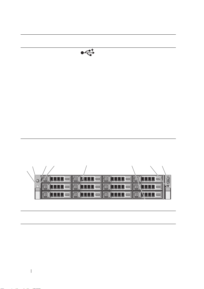
Figure 1-2. Front-Panel Features and Indicators (Twelve–Hard-Drive System)
Item Indicator, Button,
or Connector
1LED panel The LED panel has four diagnostic
16 About Your System
Icon Description
indicator lights that display error codes
during system startup. See "Diagnostic
Lights (Optional)" on page 27.

Item Indicator, Button,
or Connector
2 Power-on indicator/
power button
Icon Description
The power-on indicator lights
when the system power is on.
The power button controls the
DC power supply output to the system.
When the optional system bezel is
installed, the power button is not
accessible.
NOTE: When powering on the system,
the video monitor can take from several
seconds to over 2 minutes to display an
image, depending on the amount of
memory installed in the system.
NOTE: On ACPI-compliant operating
systems, turning off the system using the
power button causes the system to
perform a graceful shutdown before
power to the system is turned off.
NOTE: To force an ungraceful shutdown,
press and hold the power button for
five seconds.
3 NMI button Used to troubleshoot software and
device driver errors when using certain
operating systems. This button can be
pressed using the end of a paper clip.
Use this button only if directed to do so
by qualified support personnel or by the
operating system's documentation.
4 System identification
button
5 Hard drives Up to twelve 3.5-inch or 2.5-inch,
The identification buttons on the front
and back panels can be used to locate
a particular system within a rack.
When one of these buttons is pushed,
the LCD panel on the front and the blue
system status indicator on the back blink
until one of the buttons is pushed again.
hot-swappable SAS or SATA drives.
About Your System 17
Item Indicator, Button,
1
243
or Connector
6 System identification
panel
7 USB connector Connect USB devices to the system.
8 Video connector Connects a monitor to the system.
Icon Description
A slide-out panel for system information
including the Express Service tag,
embedded NIC MAC address, and
iDRAC6 Enterprise card MAC address.
The ports are USB 2.0-compliant.
LCD Panel Features (Optional)
NOTE: This section is applicable only to eight–hard-drive systems. For four–hard-
drive and eight–hard-drive systems, see "Diagnostic Lights (Optional)" on page 27.
The system's LCD panel provides system information and status and error
messages to signify when the system is operating correctly or when the system
needs attention. See "LCD Status Messages (Optional)" on page 29 for
information on specific status codes.
The LCD backlight lights blue during normal operating conditions and lights
amber to indicate an error condition. When the system is in standby mode,
the LCD backlight switches off after five minutes of inactivity, and can be
turned on by pressing the Select button on the LCD panel. The LCD
backlight remains off if LCD messaging is turned off through the BMC or
iDRAC utility, the LCD panel, or other tools.
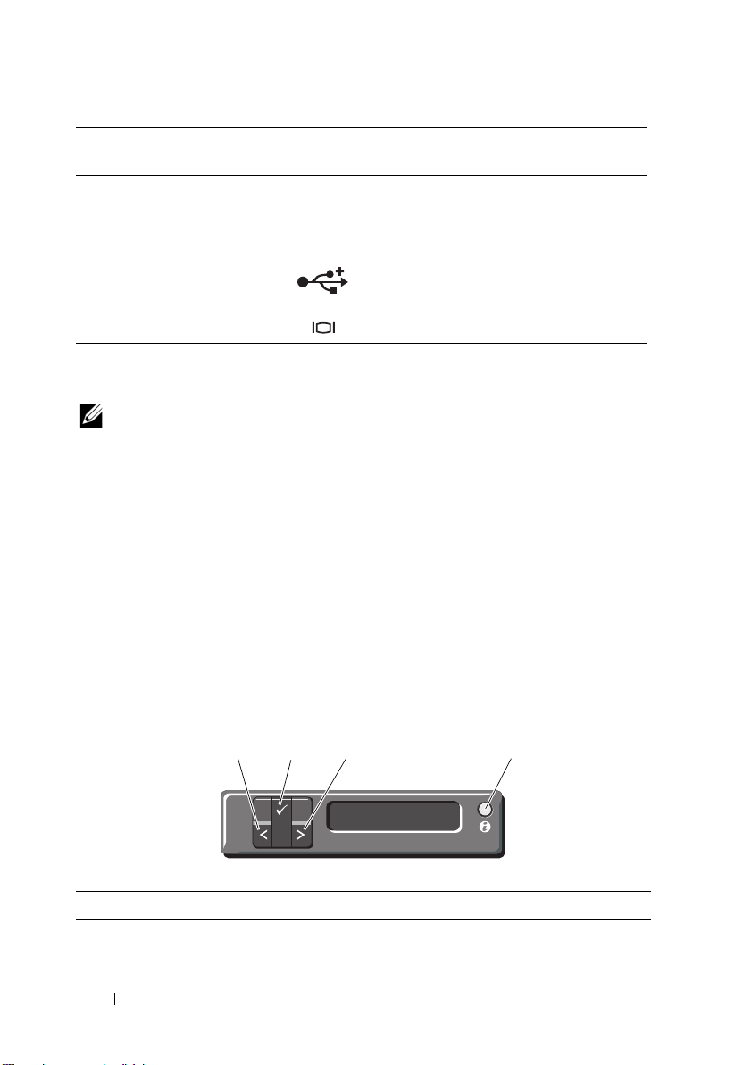
Figure 1-3. LCD Panel Features
Item Buttons Description
1 Left Moves the cursor back in one-step increments.
18 About Your System

Item Buttons Description
2 Select Selects the menu item highlighted by the cursor.
3 Right Moves the cursor forward in one-step
increments.
During message scrolling:
• Press once to increase scrolling speed.
• Press again to stop.
• Press again to return to default scrolling.
• Press again to repeat the cycle.
4 System ID Turns the system ID mode on and off.
Press quickly to toggle the system ID on and off.
If the system hangs during POST, press and hold
the system ID button for more than 5 seconds to
enter BIOS Progress mode.
Home Screen
The Home screen displays user-configurable information about the system.
This screen is displayed during normal system operation when there are no
status messages or errors present. When the system is in standby mode,
the LCD backlight turns off after 5 minutes of inactivity if there are no error
messages. Press one of the three navigation buttons (Select, Left, or Right) to
view the Home screen.
To navigate to the Home screen from another menu, continue to select the
up arrow until the Home icon is displayed, and then select the
Home icon.
About Your System 19

Setup Menu
Option Description
BMC or DRAC
NOTE: If an iDRAC6
Express card is
installed on the system,
the BMC option is
replaced by DRAC.
Set error Select SEL to display LCD error messages in a format that
Set home Select the default information to be displayed on the LCD
Select DHCP or Static IP to configure the network mode.
If Static IP is selected, the available fields are IP, Subnet
(Sub), and Gateway (Gtw). Select Setup DNS to enable DNS
and to view domain addresses. Two separate DNS entries are
available.
matches the IPMI description in the SEL. This can be useful
when trying to match an LCD message with an SEL entry.
Select Simple to display LCD error messages in a more
user-friendly description. See "LCD Status Messages
(Optional)" on page 29 for a list of messages in this format.
Home screen. See "View Menu" on page 20 to see the options
and option items that can be selected to display by default on
the Home screen.
View Menu
Option Description
BMC IP or DRAC IP
NOTE: If an iDRAC6
Express card is
installed on the
system, the BMC
IP option is replaced
by DRAC IP.
MAC Displays the MAC addresses for DRAC, iSCSIn, or NETn.
Name Displays the name of the Host, Model, or User String
Number Displays the Asset tag or the Service tag for the system.
Displays the IPv4 or IPv6 addresses for the optional iDRAC6.
Addresses include DNS (Primary and Secondary), Gateway, IP,
and Subnet (IPv6 does not have Subnet).
NOTE: BMC IP supports only IPv4 addresses.
NOTE: If the iDRAC6 Express card is not installed on the system,
the MAC option displays the MAC addresses for BMC, iSCSIn,
or NETn.
for the system.
20 About Your System
Option Description
1
2
Power Displays the power output of the system in BTU/hr or Watts.
The display format can be configured in the "Set home"
submenu of the Setup menu (see "Setup Menu" on page 20).
Temperature Displays the temperature of the system in Celsius or
Fahrenheit. The display format can be configured in the "Set
home" submenu of the Setup menu (see "Setup Menu" on
page 20).
Hard-Drive Indicator Patterns
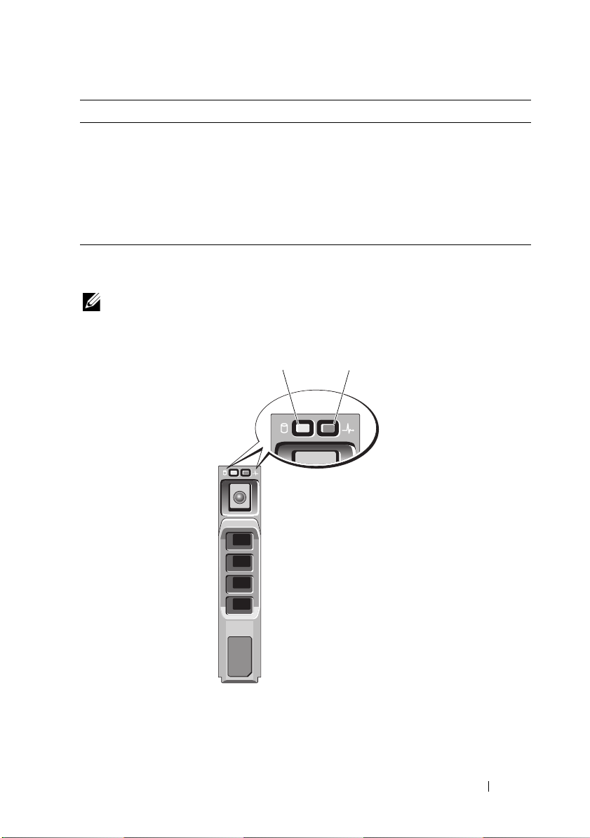
NOTE: This section is applicable to systems with hot-swappable hard drives only.
Figure 1-4. Hard-Drive Indicators
1 hard-drive activity indicator
(green)
2 hard-drive status indicator
(green and amber)
About Your System 21
Drive-Status Indicator Pattern Condition
ST
1
3
2
1
2
Gb 2
Gb 1
2
1
3
4
6
9
10
11 12
8
7
5
Blinks green two times per second Identify drive/preparing for removal
Off Drive ready for insertion or removal
NOTE: The drive status indicator remains off
until all hard drives are initialized after system
power is applied. Drives are not ready for
insertion or removal during this time.
Blinks green, amber, and off Drive predicted failure
Blinks amber four times per second Drive failed
Blinks green slowly Drive rebuilding
Steady green Drive online
Blinks green three seconds, off three
Rebuild aborted
seconds, amber three seconds, and off
three seconds.
Back-Panel Features and Indicators
Figure 1-5 shows the controls, indicators, and connectors located on the back
panel of the system.
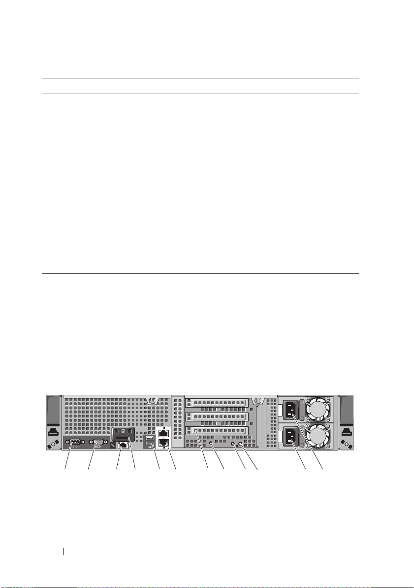
Figure 1-5. Back-Panel Features and Indicators
22 About Your System
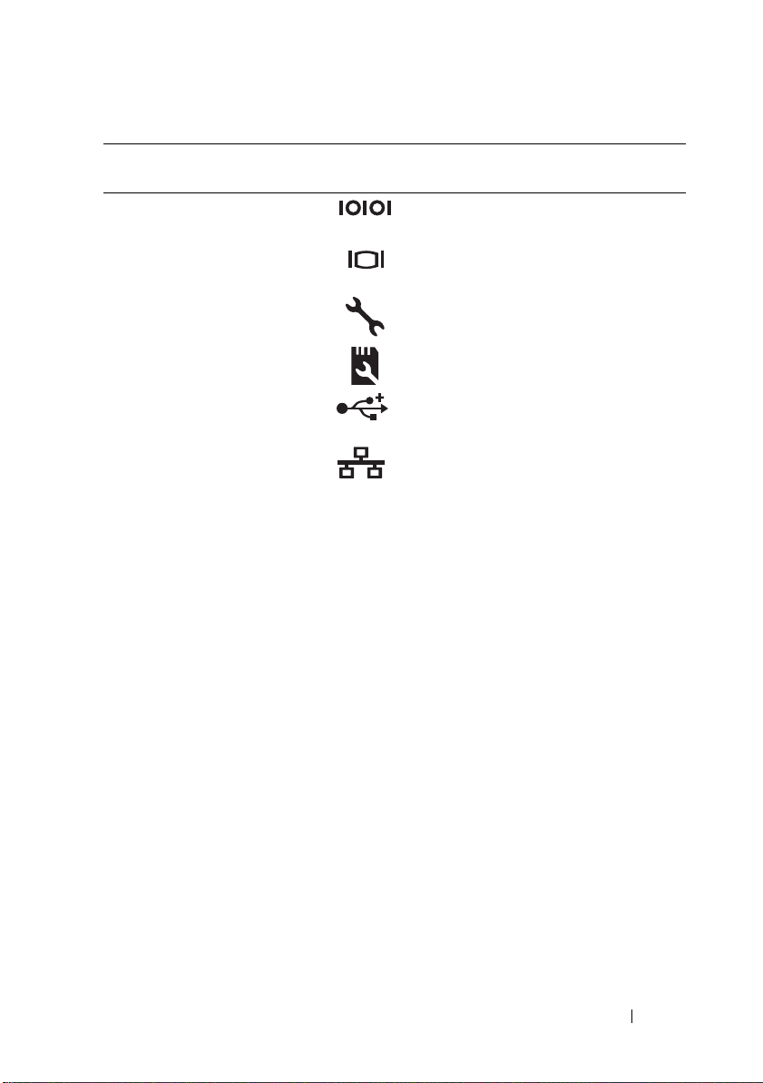
Item Indicator, Button, or
Connector
1 Serial connector Connects a serial device to the system.
2 Video connector Connects a VGA display to the system.
Icon Description
3 iDRAC6 Enterprise
port (optional)
4 VFlash media slot
(optional)
5 USB connectors (2) Connect USB devices to the system.
6 Ethernet connectors (2) Embedded 10/100/1000 NIC
7 PCIe expansion card
slots using riser card
Dedicated management port for the
optional iDRAC6 Enterprise card.
Connects an external SD memory card
for the optional iDRAC6 Enterprise card.
The ports are USB 2.0-compliant.
connectors.
Depending on the configuration, your
system may have either riser 1 or riser 2.
NOTE: See the Getting Started Guide
that ships with your system for more
information.
Riser 1
OR
Riser 2
Connects four PCI Express Generation
2 expansion cards
NOTE: All four slots are x8 connectors.
Connects two PCI Express Generation
2 expansion cards.
NOTE: A General Purpose Computation
on Graphics Processing Units (GPGPU)
optimized configuration is available on
Riser 2.
8 System identification
connector
Connects the optional system status
indicator assembly through the
optional cable management arm.
About Your System 23

Item Indicator, Button, or
Connector
9 System status
indicator
10 System identification
button
11 Power supply 2 (PS2) 750 W/1100 W redundant power
12 Power supply 1 (PS1) 750 W/1100 W redundant power
Icon Description
Lights blue during normal
system operation.
Both the systems management software
and the identification buttons located
on the front and back of the system can
cause the indicator to flash blue to
identify a particular system.
Lights amber when the system needs
attention due to a problem.
Turns the system ID modes on and off.
The identification buttons on the front
and back panels can be used to locate a
particular system within a rack. When
one of these buttons is pushed, the
LCD panel on the front and the system
status indicator on the chassis back
panel light blue until one of the
buttons is pushed again.
supply
supply
NOTE: Systems with cabled hard drives
support a non-redundant power supply
unit of 480 W.
24 About Your System
Guidelines for Connecting Optional
1
2
External Devices
• Turn off power to the system and external devices before attaching a new
external device. Turn on any external devices before turning on the system
(unless the documentation for the device specifies otherwise).
• Ensure that the appropriate driver for the attached device has been
installed on the system.
• If necessary to enable ports on your system, use the System Setup program.
S
ee "Using the System Setup Program and UEFI Boot Manager
page 61
.
" on
NIC Indicator Codes
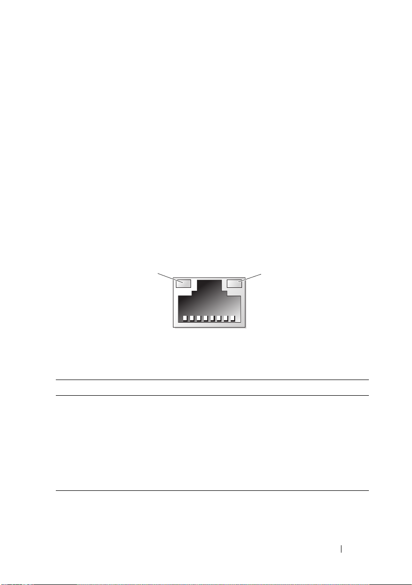
Figure 1-6. NIC Indicators
1 link indicator 2 activity indicator
Indicator Indicator Code
Link and activity
indicators are off
Link indicator is green The NIC is connected to a valid network link
Link indicator is amber The NIC is connected to a valid network link
Activity indicator is green Network data is being sent or received.
The NIC is not connected to the network.
at 1000 Mbps.
at 10/100 Mbps.
About Your System 25
Power Indicator Codes
1
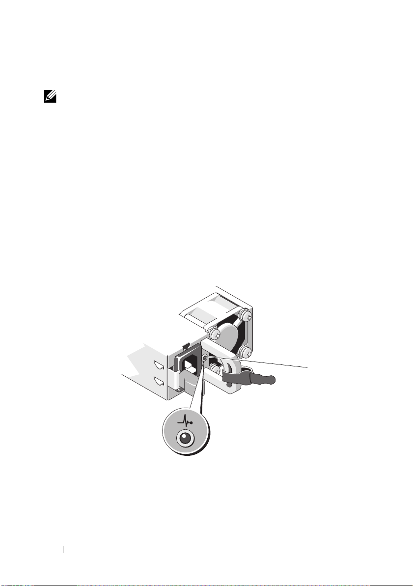
NOTE: This section is applicable to systems with redundant power supplies only.
The power supplies have an indicator that shows whether power is present or
whether a power fault has occurred.
• Not lit — AC power is not connected.
• Green — In standby mode, indicates that a valid AC source is connected
to the power supply, and that the power supply is operational. When the
system is on, it also indicates that the power supply is providing DC power
to the system.
• Amber — Indicates a problem with the power supply.
• Alternating green and amber — When hot-adding a power supply, this
indicates that the power supply is mismatched with the other power supply.
Replace the power supply that has the flashing indicator with a power supply
that matches the capacity of the other installed power supply.
Figure 1-7. Power Supply Status Indicator
1 power supply status
26 About Your System
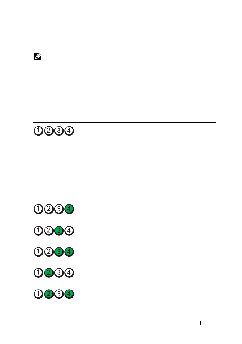
Diagnostic Lights (Optional)
NOTE: This section is applicable to twelve–hard-drive systems and systems with
cabled hard drives only.
The four diagnostic indicator lights on the system front panel display error
codes during system startup. Table 1-1 lists the causes and possible corrective
actions associated with these codes. A highlighted circle indicates the light is
on; a non-highlighted circle indicates the light is off.
Table 1-1. Diagnostic Indicator Codes
Code Causes Corrective Action
The system is in a normal
off condition or a possible
pre-BIOS failure has
occurred.
The diagnostic lights are
not lit after the system
successfully boots to the
operating system.
The system is in a normal
operating condition
after POST.
BIOS checksum failure
detected; system is in
recovery mode.
Possible processor failure. See "Troubleshooting Processors"
Plug the system into a working
electrical outlet and press the
power button.
Information only.
See "Getting Help" on page 199.
on page 186.
Memory failure. See "Troubleshooting System
Memory" on page 177.
Possible expansion card
failure.
Possible video failure. See "Getting Help" on page 199.
See "Troubleshooting Expansion
Cards" on page 184.
About Your System 27

Table 1-1. Diagnostic Indicator Codes
Code Causes Corrective Action
Hard drive failure. Ensure that the diskette drive and
hard drive are properly connected.
See "Hard Drives" on page 91 for
information on the drives
installed in your system.
Possible USB failure. See "Troubleshooting a USB
Device" on page 170.
No memory modules
detected.
System board failure. See "Getting Help" on page 199.
Memory configuration
error.
Possible system board
resource and/or system
board hardware failure.
Possible system resource
configuration error.
Other failure. Ensure that the optical drive,
See "Troubleshooting System
Memory" on page 177.
See "Troubleshooting System
Memory" on page 177.
See "Getting Help" on page 199.
See "Contacting Dell" on
page 199.
and hard drives are properly
connected. See "Troubleshooting
Your System" on page 169 for the
appropriate drive installed in your
system. If the problem persists,
see "Getting Help" on page 199.
28 About Your System

LCD Status Messages (Optional)
NOTE: This section is applicable only to eight–hard-drive systems.
The system's control panel LCD provides status messages to signify when the
system is operating correctly or when the system needs attention.
The LCD lights blue to indicate a normal operating condition, and lights
amber to indicate an error condition. The LCD scrolls a message that
includes a status code followed by descriptive text. The table that follows
provides a listing of LCD status messages and the probable cause for each
message. The LCD messages refer to events recorded in the system event log
(SEL). For information on the SEL and configuring system management
settings, see the systems management software documentation.
NOTE: If your system fails to boot, press the System ID button for at least five
seconds until an error code appears on the LCD. Record the code, then see "Getting
Help" on page 199.
Code Text Causes Corrective Actions
N/A
E1000 Failsafe
SYSTEM NAME A 62-character string that
can be defined by the user
in the System Setup
program.
voltage
error.
Contact
support.
SYSTEM NAME
The
displays under the
following conditions:
• The system is
powered on.
• The power is off and
active errors are
displayed.
Check the system
event log for critical
failure events.
This message is for
information only.
You can change the
system ID and name in
the System Setup
program. See "Using the
System Setup Program
and UEFI Boot Manager"
on page 61.
Remove AC power to the
system for 10 seconds and
restart the system.
If the problem persists,
see "Getting Help" on
page 199.
About Your System 29

Code Text Causes Corrective Actions
E1114 Ambient Temp
exceeds
allowed range.
E1116 Memory
disabled,
temp above
range.
Power
cycle AC.
E1210 Motherboard
battery
failure.
Check
battery.
E1211 RAID
Controller
battery
failure.
Check
battery.
E1216 3.3V Regulator
failure.
Reseat PCIe
cards.
E1229 CPU # VCORE
Regulator
failure.
Reseat CPU.
Ambient temperature has
a reached a point outside
of the allowed range.
Memory has exceeded
allowable temperature and
has been disabled to
prevent damage to the
components.
CMOS battery is missing
or the voltage is outside of
the allowable range.
RAID battery is either
missing, bad, or unable
to recharge due
to thermal issues.
3.3 V voltage regulator
has failed.
Specified processor
VCORE voltage
regulator has failed.
See "Troubleshooting
System Cooling
Problems" on page 176.
Remove AC power to the
system for 10 seconds and
restart the system.
See "Troubleshooting
System Cooling
Problems" on page 176.
If the problem persists,
see "Getting Help" on
page 199.
See "Troubleshooting the
System Battery" on
page 174.
Reseat the RAID battery
connector. See "Installing
the RAID Battery" on
page 147, and
"Troubleshooting System
Cooling Problems" on
page 176.
Remove and reseat the
PCIe expansion cards.
If the problem persists,
see "Troubleshooting
Expansion Cards" on
page 184.
Reseat the processor(s).
See "Troubleshooting
Processors" on page 186.
If the problem persists,
see "Getting Help" on
page 199.
30 About Your System
 Loading...