

Page 1

Precision 7750
Service Manual
Regulatory Model: P44E
Regulatory Type: P44E001
May 2020
Rev. A00
Page 2

Hinweise, Vorsichtshinweise und Warnungen
ANMERKUNG: Eine ANMERKUNG macht auf wichtige Informationen aufmerksam, mit denen Sie Ihr Produkt besser
einsetzen können.
VORSICHT: Ein VORSICHTSHINWEIS warnt vor möglichen Beschädigungen der Hardware oder vor Datenverlust und
zeigt, wie diese vermieden werden können.
WARNUNG: Mit WARNUNG wird auf eine potenziell gefährliche Situation hingewiesen, die zu Sachschäden,
Verletzungen oder zum Tod führen kann.
© 2020 Dell Inc. oder ihre Tochtergesellschaften. Alle Rechte vorbehalten. Dell, EMC und andere Marken sind Marken von Dell Inc. oder
entsprechenden Tochtergesellschaften. Andere Marken können Marken ihrer jeweiligen Inhaber sein.
Page 3

Contents
1 Arbeiten am Computer.................................................................................................................. 6
Sicherheitshinweise...............................................................................................................................................................6
Vor der Arbeit an Komponenten im Innern des Computers....................................................................................... 6
Sicherheitsvorkehrungen................................................................................................................................................ 7
Schutz vor elektrostatischer Entladung........................................................................................................................7
ESD-Service-Kit...............................................................................................................................................................8
Nach der Arbeit an Komponenten im Inneren des Computers.................................................................................. 9
2 Technologie und Komponenten.................................................................................................... 10
USB-Funktionen...................................................................................................................................................................10
USB Typ-C.............................................................................................................................................................................11
HDMI 2.0............................................................................................................................................................................... 13
NVIDIA Quadro T1000......................................................................................................................................................... 14
NVIDIA Quadro RTX3000................................................................................................................................................... 14
NVIDIA Quadro RTX4000................................................................................................................................................... 15
NVIDIA Quadro RTX5000...................................................................................................................................................15
3 Ausbau und Wiedereinbau............................................................................................................17
SD-Karte................................................................................................................................................................................17
Entfernen der SD-Karte.................................................................................................................................................17
Installieren der SD-Karte................................................................................................................................................17
SSD-Zugangsklappe.............................................................................................................................................................17
Removing SSD door....................................................................................................................................................... 17
Installing SSD door......................................................................................................................................................... 18
Sekundäres M.2 SSD-Laufwerk.........................................................................................................................................19
Removing the secondary M.2 Solid-state drive......................................................................................................... 19
Installing the secondary M.2 SSD module..................................................................................................................20
Bodenabdeckung..................................................................................................................................................................21
Removing the base cover..............................................................................................................................................21
Installing the base cover............................................................................................................................................... 24
Akku.......................................................................................................................................................................................26
Vorsichtshinweise zu Lithium-Ionen-Akkus................................................................................................................26
Removing the battery................................................................................................................................................... 26
Installing the battery......................................................................................................................................................27
SSD-Laufwerk......................................................................................................................................................................28
Removing the primary M.2 Solid-state drive............................................................................................................. 28
Installing the primary M.2 SSD module.......................................................................................................................30
Sekundäres Speichermodul.................................................................................................................................................31
Removing the secondary memory module..................................................................................................................31
Installing the secondary memory module................................................................................................................... 32
SIM-Karte.............................................................................................................................................................................32
Removing the SIM card................................................................................................................................................ 32
Installing the SIM card...................................................................................................................................................33
WLAN-Karte.........................................................................................................................................................................34
Contents 3
Page 4

Removing the WLAN card............................................................................................................................................34
Installing the WLAN card..............................................................................................................................................35
WWAN-Karte.......................................................................................................................................................................36
Removing the WWAN card..........................................................................................................................................36
Installing the WWAN card............................................................................................................................................ 36
Tastaturgitter....................................................................................................................................................................... 37
Removing the keyboard lattice.................................................................................................................................... 37
Installing the keyboard lattice.......................................................................................................................................38
Tastatur................................................................................................................................................................................ 38
Removing the keyboard................................................................................................................................................38
Installing the keyboard.................................................................................................................................................. 39
Primäres Speichermodul......................................................................................................................................................41
Removing the primary memory module.......................................................................................................................41
Installing the primary memory module........................................................................................................................ 42
Kühlkörper............................................................................................................................................................................ 43
Removing the heat-sink assembly...............................................................................................................................43
Installing the heat sink assembly..................................................................................................................................44
Netzadapteranschluss........................................................................................................................................................ 45
Removing the power-adapter port............................................................................................................................. 45
Installing the power-adapter port................................................................................................................................45
Betriebsschalterplatine....................................................................................................................................................... 46
Removing the power button board.............................................................................................................................46
Installing the power button board................................................................................................................................47
Netzschalterplatine mit Fingerabdruckleser.....................................................................................................................47
Removing the power button assembly with fingerprint reader............................................................................... 47
Installing the power button assembly with fingerprint reader................................................................................. 48
Innerer Rahmen................................................................................................................................................................... 49
Removing the inner frame............................................................................................................................................49
Installing the inner frame.............................................................................................................................................. 50
Smart Card-Kartenträger....................................................................................................................................................51
Removing the smart-card reader.................................................................................................................................51
Installing the smart-card reader...................................................................................................................................52
Touchpad-Taste.................................................................................................................................................................. 53
Removing the Touchpad buttons................................................................................................................................53
Installing the Touchpad buttons.................................................................................................................................. 54
SD-Kartenleser.................................................................................................................................................................... 55
Removing SD card reader............................................................................................................................................ 55
Installing SD card reader...............................................................................................................................................56
Netzschalter.........................................................................................................................................................................57
Removing the power button........................................................................................................................................ 57
Installing the power button.......................................................................................................................................... 58
Netzschalterbaugruppe mit Fingerabdruckleser............................................................................................................. 59
Removing the power button assembly with fingerprint reader...............................................................................59
Installing the power button assembly with fingerprint reader................................................................................. 60
GPU-Stromkabel................................................................................................................................................................. 60
Removing the GPU power cable................................................................................................................................. 60
Installing the GPU power cable.................................................................................................................................... 61
Systemplatine.......................................................................................................................................................................62
Removing the system board........................................................................................................................................ 62
Installing the system board...........................................................................................................................................65
4
Contents
Page 5

GPU-Karte............................................................................................................................................................................68
Entfernen der GPU-Karte............................................................................................................................................ 68
Installieren der GPU-Karte........................................................................................................................................... 69
Lautsprecher........................................................................................................................................................................69
Removing the speaker.................................................................................................................................................. 69
Installing the speaker.....................................................................................................................................................70
Mittlere Abdeckung.............................................................................................................................................................72
Removing the middle cap............................................................................................................................................. 72
Installing the middle cap................................................................................................................................................73
Bildschirmbaugruppe...........................................................................................................................................................74
Removing the display assembly................................................................................................................................... 74
Installing the display assembly......................................................................................................................................76
Handballenauflage............................................................................................................................................................... 79
Removing the palmrest.................................................................................................................................................79
Installing the palmrest................................................................................................................................................... 80
Bildschirmblende...................................................................................................................................................................81
Removing the display bezel (non-touch).................................................................................................................... 81
Installing the display bezel (non-touch)......................................................................................................................82
Bildschirm............................................................................................................................................................................. 84
Removing the display panel (non-touch)................................................................................................................... 84
Installing the display panel (non-touch)......................................................................................................................86
Bildschirmscharniere........................................................................................................................................................... 87
Removing the display hinge..........................................................................................................................................87
Installing the display hinge (non-touch)......................................................................................................................88
Kamera..................................................................................................................................................................................90
Removing the camera (non-touch)............................................................................................................................ 90
Installing the camera...................................................................................................................................................... 91
P-Sensorplatine................................................................................................................................................................... 92
Entfernen der P-Sensorplatine.................................................................................................................................... 92
Installieren der P-Sensorplatine................................................................................................................................... 93
Bildschirmkabel.................................................................................................................................................................... 93
Removing the display cable..........................................................................................................................................93
Installing the display cable............................................................................................................................................ 95
Display back cover...............................................................................................................................................................96
Replacing the display cable.......................................................................................................................................... 96
4 Fehlerbehebung......................................................................................................................... 98
Diagnose der Dell SupportAssist-Systemleistungsprüfung vor dem Start.................................................................. 98
Ausführen der SupportAssist-Systemleistungsprüfung vor dem Systemstart..................................................... 98
Integrierter Selbsttest für die Systemplatine (M-BIST).................................................................................................99
Integrierter Selbsttest für die Stromschiene des Bildschirms (L-BIST).......................................................................99
Integrierter Bildschirmselbsttest (LCD-BIST)................................................................................................................100
Systemdiagnoseanzeigen................................................................................................................................................. 100
Ein- und Ausschalten des WLAN..................................................................................................................................... 102
5 Wie Sie Hilfe bekommen............................................................................................................ 103
Kontaktaufnahme mit Dell................................................................................................................................................ 103
Contents
5
Page 6

Arbeiten am Computer
Sicherheitshinweise
Voraussetzungen
Beachten Sie folgende Sicherheitsrichtlinien, damit Ihr Computer vor möglichen Schäden geschützt und Ihre eigene Sicherheit
sichergestellt ist. Wenn nicht anders angegeben, wird bei jedem in diesem Dokument vorgestellten Verfahren vorausgesetzt, dass
folgende Bedingungen zutreffen:
• Sie haben die im Lieferumfang des Computers enthaltenen Sicherheitshinweise gelesen.
• Eine Komponente kann ersetzt oder, wenn sie separat erworben wurde, installiert werden, indem der Entfernungsvorgang in
umgekehrter Reihenfolge ausgeführt wird.
Info über diese Aufgabe
ANMERKUNG: Trennen Sie den Computer vom Netz, bevor Sie die Computerabdeckung oder Verkleidungselemente
entfernen. Bringen Sie nach Abschluss der Arbeiten innerhalb des Tablets alle Abdeckungen, Verkleidungselemente und
Schrauben wieder an, bevor Sie das Gerät erneut an das Stromnetz anschließen.
WARNUNG: Bevor Sie Arbeiten im Inneren des Computers ausführen, lesen Sie zunächst die im Lieferumfang des
Computers enthaltenen Sicherheitshinweise. Zusätzliche Informationen zur bestmöglichen Einhaltung der
Sicherheitsrichtlinien finden Sie auf der Homepage zur Einhaltung behördlicher Auflagen.
1
VORSICHT: Manche Reparaturarbeiten dürfen nur von qualifizierten Servicetechnikern durchgeführt werden.
Maßnahmen zur Fehlerbehebung oder einfache Reparaturen sollten Sie nur dann selbst durchführen, wenn dies laut
Produktdokumentation genehmigt ist, oder wenn Sie vom Team des Online- oder Telefonsupports dazu aufgefordert
werden. Schäden durch nicht von Dell genehmigte Wartungsversuche werden nicht durch die Garantie abgedeckt.
Lesen und beachten Sie die Sicherheitshinweise, die Sie zusammen mit Ihrem Produkt erhalten haben.
VORSICHT: Um elektrostatische Entladungen zu vermeiden, erden Sie sich mittels eines Erdungsarmbandes oder durch
regelmäßiges Berühren einer nicht lackierten metallenen Oberfläche (beispielsweise eines Anschlusses auf der
Rückseite des Computers).
VORSICHT: Gehen Sie mit Komponenten und Erweiterungskarten vorsichtig um. Berühren Sie keine Komponenten oder
Kontakte auf der Karte. Halten Sie die Karte möglichst an ihren Kanten oder dem Montageblech. Fassen Sie
Komponenten wie Prozessoren grundsätzlich an den Kanten und niemals an den Kontaktstiften an.
VORSICHT: Ziehen Sie beim Trennen eines Kabels vom Computer nur am Stecker oder an der Zuglasche und nicht am
Kabel selbst. Einige Kabel haben Stecker mit Sicherungsklammern. Wenn Sie ein solches Kabel abziehen, drücken Sie
vor dem Herausziehen des Steckers die Sicherungsklammern nach innen. Ziehen Sie beim Trennen von
Steckverbindungen die Anschlüsse immer gerade heraus, damit Sie keine Anschlussstifte verbiegen. Richten Sie vor
dem Herstellen von Steckverbindungen die Anschlüsse stets korrekt aus.
ANMERKUNG: Die Farbe Ihres Computers und bestimmter Komponenten kann von den in diesem Dokument gezeigten
Farben abweichen.
Vor der Arbeit an Komponenten im Innern des Computers
Info über diese Aufgabe
Um Schäden am Computer zu vermeiden, führen Sie folgende Schritte aus, bevor Sie mit den Arbeiten im Computerinneren beginnen.
6 Arbeiten am Computer
Page 7

Schritte
1. Die Sicherheitshinweise müssen strikt befolgt werden.
2. Stellen Sie sicher, dass die Arbeitsoberfläche eben und sauber ist, damit die Computerabdeckung nicht zerkratzt wird.
3. Schalten Sie den Computer aus.
4. Trennen Sie alle Netzwerkkabel vom Computer.
VORSICHT: Wenn Sie ein Netzwerkkabel trennen, ziehen Sie es zuerst am Computer und dann am Netzwerkgerät ab.
5. Trennen Sie Ihren Computer sowie alle daran angeschlossenen Geräte vom Stromnetz.
6. Halten Sie den Betriebsschalter gedrückt, während Sie den Computer vom Netz trennen, um die Systemplatine zu erden.
ANMERKUNG: Um elektrostatische Entladungen zu vermeiden, erden Sie sich mittels eines Erdungsarmbandes oder
durch regelmäßiges Berühren einer nicht lackierten metallenen Oberfläche (beispielsweise eines Anschlusses auf der
Rückseite des Computers).
Sicherheitsvorkehrungen
Im Kapitel zu den Vorsichtsmaßnahmen werden die primären Schritte, die vor der Demontage durchzuführen sind, detailliert beschrieben.
Lesen Sie die folgenden Vorsichtsmaßnahmen vor der Durchführung von Installations- oder Reparaturverfahren, bei denen es sich um
Demontage oder Neumontage handelt:
• Schalten Sie das System und alle angeschlossenen Peripheriegeräte aus.
• Trennen Sie das System und alle angeschlossenen Peripheriegeräte von der Netzstromversorgung.
• Trennen Sie alle Netzwerkkabel, Telefon- und Telekommunikationsverbindungen vom System.
• Verwenden Sie ein ESD-Service-Kit beim Arbeiten im Inneren eines TabletsNotebooks, um Schäden durch elektrostatische
Entladungen (ESD) zu vermeiden.
• Nach dem Entfernen von Systemkomponenten setzen Sie die entfernte Komponente vorsichtig auf eine antistatische Matte.
• Tragen Sie Schuhe mit nicht leitenden Gummisohlen, um das Risiko eines Stromschlags zu reduzieren.
Standby-Stromversorgung
Dell-Produkte mit Standby-Stromversorgung müssen vom Strom getrennt sein, bevor das Gehäuse geöffnet wird. Systeme mit StandbyStromversorgung werden im ausgeschalteten Zustand mit einer minimalen Stromzufuhr versorgt. Durch die interne Stromversorgung kann
das System remote eingeschaltet werden (Wake on LAN), vorübergehend in einen Ruhemodus versetzt werden und verfügt über andere
erweiterte Energieverwaltungsfunktionen.
Nach dem Trennen von der Stromversorgung und dem Gedrückthalten des Betriebsschalters für 15 Sekunden sollte der Reststrom von
der Systemplatine entladen sein. Entfernen Sie den Akku aus tragbaren TabletsNotebooks
Bonding
Bonding ist eine Methode zum Anschließen von zwei oder mehreren Erdungsleitern an dieselbe elektrische Spannung. Dies erfolgt durch
die Nutzung eines Field Service Electrostatic Discharge (ESD)-Kits. Stellen Sie beim Anschließen eines Bonddrahts sicher, dass er mit
blankem Metall und nicht mit einer lackierten oder nicht metallischen Fläche verbunden ist. Das Armband sollte sicher sitzen und sich in
vollem Kontakt mit Ihrer Haut befinden. Entfernen Sie außerdem sämtlichen Schmuck wie Uhren, Armbänder oder Ringe, bevor Sie die
Bonding-Verbindung mit dem Geräte herstellen.
Schutz vor elektrostatischer Entladung
Die elektrostatische Entladung ist beim Umgang mit elektronischen Komponenten, insbesondere empfindlichen Komponenten wie z. B.
Erweiterungskarten, Prozessoren, Speicher-DIMMs und Systemplatinen, ein wichtiges Thema. Sehr leichte Ladungen können Schaltkreise
bereits auf eine Weise schädigen, die eventuell nicht offensichtlich ist (z. B. zeitweilige Probleme oder eine verkürzte Produktlebensdauer).
Da die Branche auf geringeren Leistungsbedarf und höhere Dichte drängt, ist der ESD-Schutz von zunehmender Bedeutung.
Aufgrund der höheren Dichte von Halbleitern, die in aktuellen Produkten von Dell verwendet werden, ist die Empfindlichkeit gegenüber
Beschädigungen durch elektrostatische Entladungen inzwischen größer als bei früheren Dell-Produkten. Aus diesem Grund sind einige
zuvor genehmigte Verfahren zur Handhabung von Komponenten nicht mehr anwendbar.
Es gibt zwei anerkannte Arten von Schäden durch elektrostatische Entladung (ESD): katastrophale und gelegentliche Ausfälle.
• Katastrophal: Katastrophale Ausfälle machen etwa 20 Prozent der ESD-bezogenen Ausfälle aus. Der Schaden verursacht einen
sofortigen und kompletten Verlust der Gerätefunktion. Ein Beispiel eines katastrophalen Ausfalls ist ein Speicher-DIMM, das einen
Arbeiten am Computer
7
Page 8

elektrostatischen Schock erhalten hat und sofort das Symptom „No POST/No Video“ (Kein POST/Kein Video) mit einem
Signaltoncode erzeugt, der im Falle von fehlendem oder nicht funktionsfähigem Speicher ertönt.
• Gelegentlich: Gelegentliche Ausfälle machen etwa 80 Prozent der ESD-bezogenen Ausfälle aus. Die hohe Rate gelegentlicher
Ausfälle bedeutet, dass auftretende Schäden in den meisten Fällen nicht sofort zu erkennen sind. Das DIMM erhält einen
elektrostatischen Schock, aber die Ablaufverfolgung erfolgt nur langsam, sodass nicht sofort ausgehende Symptome im Bezug auf die
Beschädigung erzeugt werden. Die Verlangsamung der Ablaufverfolgung kann Wochen oder Monate andauern und kann in der
Zwischenzeit zur Verschlechterung der Speicherintegrität, zu zeitweiligen Speicherfehlern usw. führen.
Gelegentliche Ausfälle (auch bekannt als latente Ausfälle oder „walking wounded“) sind deutlich schwieriger zu erkennen und zu beheben.
Führen Sie die folgenden Schritte durch, um Beschädigungen durch elektrostatische Entladungen zu vermeiden:
• Verwenden Sie ein kabelgebundenes ESD-Armband, das ordnungsgemäß geerdet ist. Die Verwendung von drahtlosen antistatischen
Armbändern ist nicht mehr zulässig; sie bieten keinen ausreichenden Schutz. Das Berühren des Gehäuses vor der Handhabung von
Komponenten bietet keinen angemessenen ESD-Schutz auf Teilen mit erhöhter Empfindlichkeit auf ESD-Schäden.
• Arbeiten Sie mit statikempfindlichen Komponenten ausschließlich in einer statikfreien Umgebung. Verwenden Sie nach Möglichkeit
antistatische Bodenmatten und Werkbankunterlagen.
• Beim Auspacken einer statikempfindlichen Komponente aus dem Versandkarton, entfernen Sie die Komponente erst aus der
antistatischen Verpackung, wenn Sie bereit sind, die Komponente tatsächlich zu installieren. Stellen Sie vor dem Entfernen der
antistatischen Verpackung sicher, dass Sie statische Elektrizität aus Ihrem Körper ableiten.
• Legen Sie eine statikempfindliche Komponente vor deren Transport in einen antistatischen Behälter oder eine antistatische
Verpackung.
ESD-Service-Kit
Das nicht kontrollierte Service-Kit ist das am häufigsten verwendete Service-Kit. Jedes Service-Kit beinhaltet drei Hauptkomponenten:
antistatische Matte, Armband, und Bonddraht.
Komponenten eines ESD-Service-Kits
ESD-Service-Kits enthalten folgende Komponenten:
• Antistatische Matte: Die antistatische Matte ist ableitfähig. Während Wartungsverfahren können Sie Teile darauf ablegen. Wenn Sie
mit einer antistatischen Matte arbeiten, sollte Ihr Armband fest angelegt und der Bonddraht mit der Matte und mit sämtlichen blanken
Metallteilen im System verbunden sein, an denen Sie arbeiten. Nach ordnungsgemäßer Bereitstellung können Ersatzteile aus dem
ESD-Beutel entnommen und auf der Matte platziert werden. ESD-empfindliche Elemente sind sicher geschützt – in Ihrer Hand, auf
der ESD-Matte, im System oder innerhalb des Beutels.
• Armband und Bonddraht: Das Armband und der Bonddraht können entweder direkt zwischen Ihrem Handgelenk und blankem Metall
auf der Hardware befestigt werden, falls die ESD-Matte nicht erforderlich ist, oder mit der antistatischen Matte verbunden werden,
sodass Hardware geschützt wird, die vorübergehend auf der Matte platziert wird. Die physische Verbindung zwischen dem Armband
bzw. dem Bonddraht und Ihrer Haut, der ESD-Matte und der Hardware wird als Bonding bezeichnet. Verwenden Sie nur Service-Kits
mit einem Armband, einer Matte und Bonddraht. Verwenden Sie niemals kabellose Armbänder. Bedenken Sie immer, dass bei den
internen Kabeln eines Erdungsarmbands die Gefahr besteht, dass sie durch normale Abnutzung beschädigt werden, und daher müssen
Sie regelmäßig mit einem Armbandtester geprüft werden, um versehentliche ESD-Hardwareschäden zu vermeiden. Es wird
empfohlen, das Armband und den Bonddraht mindestens einmal pro Woche zu überprüfen.
• ESD Armbandtester: Die Kabel innerhalb eines ESD-Armbands sind anfällig für Schäden im Laufe der Zeit. Bei der Verwendung eines
nicht kontrollierten Kits sollten Sie das Armband regelmäßig vor jeder Wartungsanfrage bzw. mindestens einmal pro Woche testen. Ein
Armbandtester ist für diese Zwecke die beste Lösung. Wenn Sie keinen eigenen Armbandtester besitzen, fragen Sie bei Ihrem
regionalen Büro nach, ob dieses über einen verfügt. Stecken Sie für den Test den Bonddraht des Armbands in den Tester (während
das Armband an Ihrem Handgelenk angelegt ist) und drücken Sie die Taste zum Testen. Eine grüne LED leuchtet auf, wenn der Test
erfolgreich war. Eine rote LED leuchtet auf und ein Alarmton wird ausgegeben, wenn der Test fehlschlägt.
• Isolatorelemente: Es ist sehr wichtig, ESD-empfindliche Geräte, wie z. B. Kunststoff-Kühlkörpergehäuse, von internen Teilen
fernzuhalten, die Isolatoren und oft stark geladen sind.
• Arbeitsumgebung: Vor der Bereitstellung des ESD-Service-Kits sollten Sie die Situation am Standort des Kunden überprüfen. Zum
Beispiel unterscheidet sich die Bereitstellung des Kits für eine Serverumgebung von der Bereitstellung für eine Desktop-PC- oder
mobile Umgebung. Server werden in der Regel in einem Rack innerhalb eines Rechenzentrums montiert. Desktop-PCs oder tragbare
Geräte befinden sich normalerweise auf Schreibtischen oder an Arbeitsplätzen. Achten Sie stets darauf, dass Sie über einen großen,
offenen, ebenen und übersichtlichen Arbeitsbereich mit ausreichend Platz für die Bereitstellung des ESD-Kits und mit zusätzlichem
Platz für den jeweiligen Systemtyp verfügen, den Sie reparieren. Der Arbeitsbereich sollte zudem frei von Isolatoren sein, die zu einem
ESD-Ereignis führen können. Isolatoren wie z. B. Styropor und andere Kunststoffe sollten vor dem physischen Umgang mit
Hardwarekomponenten im Arbeitsbereich immer mit mindestens 12" bzw. 30 cm Abstand von empfindlichen Teilen platziert werden.
• ESD-Verpackung: Alle ESD-empfindlichen Geräte müssen in einer Schutzverpackung zur Vermeidung von elektrostatischer
Aufladung geliefert und empfangen werden. Antistatische Beutel aus Metall werden bevorzugt. Beschädigte Teile sollten Sie immer
unter Verwendung des gleichen ESD-Beutels und der gleichen ESD-Verpackung zurückschicken, die auch für den Versand des Teils
8
Arbeiten am Computer
Page 9

verwendet wurde. Der ESD-Beutel sollte zugefaltet und mit Klebeband verschlossen werden und Sie sollten dasselbe
Schaumstoffverpackungsmaterial verwenden, das in der Originalverpackung des neuen Teils genutzt wurde. ESD-empfindliche Geräte
sollten aus der Verpackung nur an einer ESD-geschützten Arbeitsfläche entnommen werden und Ersatzteile sollte nie auf dem ESDBeutel platziert werden, da nur die Innenseite des Beutels abgeschirmt ist. Legen Sie Teile immer in Ihre Hand, auf die ESD-Matte, ins
System oder in einen antistatischen Beutel.
• Transport von empfindlichen Komponenten: Wenn empfindliche ESD-Komponenten, wie z. B. Ersatzteile oder Teile, die an Dell
zurückgesendet werden sollen, transportiert werden, ist es äußerst wichtig, diese Teile für den sicheren Transport in antistatischen
Beuteln zu platzieren.
ESD-Schutz – Zusammenfassung
Es wird empfohlen, dass Servicetechniker das herkömmliche verkabelte ESD-Erdungsarmband und die antistatische Matte jederzeit bei
der Wartung von Dell Produkten verwenden. Darüber hinaus ist es äußerst wichtig, dass Techniker während der Wartung empfindliche
Teile separat von allen Isolatorteilen aufbewahren und dass sie einen antistatischen Beutel für den Transport empfindlicher Komponenten
verwenden.
Nach der Arbeit an Komponenten im Inneren des Computers
Info über diese Aufgabe
Stellen Sie nach Abschluss von Aus- und Einbauvorgängen sicher, dass Sie zuerst sämtliche externen Geräte, Karten, Kabel usw. wieder
anschließen, bevor Sie den Computer einschalten.
Schritte
1. Schließen Sie die zuvor getrennten Telefon- und Netzwerkkabel wieder an den Computer an.
VORSICHT:
danach mit dem Computer.
2. Schließen Sie den Computer sowie alle daran angeschlossenen Geräte an das Stromnetz an.
3. Schalten Sie den Computer ein.
4. Überprüfen Sie gegebenenfalls, ob der Computer einwandfrei läuft, indem Sie SupportAssist diagnostic ausführen.
Wenn Sie ein Netzwerkkabel anschließen, verbinden Sie das Kabel zuerst mit dem Netzwerkgerät und
Arbeiten am Computer
9
Page 10
Technologie und Komponenten
Dieses Kapitel erläutert die in dem System verfügbare Technologie und Komponenten.
Themen:
• USB-Funktionen
• USB Typ-C
• HDMI 2.0
• NVIDIA Quadro T1000
• NVIDIA Quadro RTX3000
• NVIDIA Quadro RTX4000
• NVIDIA Quadro RTX5000
USB-Funktionen
Universal Serial Bus (USB) wurde 1996 eingeführt. Es hat die Verbindung zwischen Host-Computern und Peripheriegeräten wie
Computermäusen, Tastaturen, externen Laufwerken und Druckern erheblich vereinfacht.
Tabelle 1. USB-Entwicklung
Typ Datenübertragungsrate Kategorie Einführungsjahr
2
USB 2.0 480 Mbit/s Hi-Speed 2000
USB 3.2 Gen 1 (zuvor
USB 3.0/USB 3.1 Gen
1)-
USB 3.1-Anschlüsse
Gen. 2
5 GBit/s SuperSpeed 2010
10 Gbit/s SuperSpeed Plus 2013
USB 3.2 Gen 1 (SuperSpeed USB)
Viele Jahre lang war der USB 2.0 in der PC-Welt der Industriestandard für Schnittstellen. Das zeigen die etwa 6 Milliarden verkauften
Geräte. Der Bedarf an noch größerer Geschwindigkeit ist jedoch durch die immer schneller werdende Computerhardware und die
Nachfrage nach größeren Bandbreiten gestiegen. Der USB 3.0/USB 3.1 Gen 1 hat endlich die Antwort auf die Anforderungen der
Verbraucher. Er ist theoretisch 10 mal schneller als sein Vorgänger. Eine Übersicht der USB 3.2 Gen 1-Funktionen:
• Höhere Übertragungsraten (bis zu 20 Gbit/s).
• Erhöhter mehrspuriger Betrieb von jeweils 10 Gbit/s.
• Erhöhte maximale Busleistung und erhöhte Gerätestromaufnahme, um ressourcenintensiven Geräten besser zu entsprechen
• Neue Funktionen zur Energieverwaltung.
• Vollduplex-Datenübertragungen und Unterstützung für neue Übertragungsarten.
• Abwärtskompatibilität mit USB 3.1/3.0 und USB 2.0.
• Neue Anschlüsse und Kabel
In den folgenden Abschnitten werden einige der am häufigsten gestellten Fragen zu USB 3.0/USB 3.2 Gen 1 behandelt.
10 Technologie und Komponenten
Page 11

Geschwindigkeit
Die aktuelle USB 3.0/USB-3.1 Gen 1-Spezifikation definiert fünf Geschwindigkeitsmodi: Basierend auf USB-Datenübertragung werden Sie
als niedrige Geschwindigkeit, volle Geschwindigkeit, hohe Geschwindigkeit (ab Version 2.0 der Spezifikation), SuperSpeed (ab Version 3.0)
und SuperSpeed+ (ab Version 3.1) kategorisiert. Der neue SuperSpeed+-Modus hat eine Übertragungsrate von 20 Gbit/s. Der USB 3.2Standard ist abwärtskompatibel mit USB 3.1/3.0 und USB 2.0.
Aufgrund der nachstehend aufgeführten Änderungen erreicht der USB 3.2 Gen 1 wesentlich höhere Leistungen:
• Ein zusätzlicher physischer Bus, der parallel zum vorhandenen USB 2.0-Bus hinzugefügt wird (siehe Abbildung unten).
• USB 2.0 hatte vier Drähte (Strom, Masse und zwei für differentielle Daten); USB 3.1 Gen 1 ergänzt diese durch vier weitere Drähte für
zwei Differenzsignale (Empfangen und Übertragen) zu insgesamt acht Verbindungen in den Anschlüssen und Kabeln.
• USB 3.2 Gen 1 nutzt anstatt der Halb-Duplex-Anordnung von USB 2.0 die bidirektionalen Datenschnittstelle. Das erweitert die
theoretische Bandbreite um das 10-fache.
Anwendungen
USB 3.1 Gen 1 öffnet Wege und bietet Geräten mehr Raum für bessere Gesamtfunktionalität. USB-Video war zuvor was maximale
Auflösung, Latenz und Videokomprimierung anbelangt nicht akzeptabel. Aufgrund der 5- bis 10-mal größeren Bandbreite lassen sich nun
weitaus bessere USB-Videolösungen vorstellen. Single-link-DVI erfordert einen Durchsatz von nahezu 2 Gbit/s. 480 Mbit/s legte
Beschränkungen auf, 5 Gbit/s ist mehr als vielversprechend. Mit der versprochenen Geschwindigkeit von 4,8 Gbit/s wird der Standard für
Produkte interessant, die zuvor kein USB-Territorium waren, beispielsweise für externe RAID-Speichersysteme.
Im Folgenden sind einige der verfügbaren Super-Speed USB 3.0/USB 3.1 Gen 1-Produkte aufgeführt:
• Externe Desktop-Festplatten mit USB 3.0/USB 3.2 Gen 1
• Portable USB 3.2 Gen 1-Festplatten
• USB 3.2 Gen 1-Laufwerk-Docks und -Adapter
• USB 3.2 Gen 1-Flash-Laufwerke und -Lesegeräte
• USB 3.2 Gen 1-Solid-State-Laufwerke
• USB 3.2 Gen 1-RAIDs
• Optische Medien/Laufwerke
• Multimedia-Geräte
• Netzwerkbetrieb
• USB 3.2 Gen 1-Adapterkarten und -Hubs
Kompatibilität
Gute Nachrichten: USB 3.2 Gen 1 wurde von Anfang an so geplant, dass es mit USB 2.0 friedlich koexistieren kann. USB 3.2 Gen 1 gibt
neue physische Verbindungen an. Daher profitieren neue Kabel von den höheren Geschwindigkeitsmöglichkeiten des neuen Protokolls. Der
Anschluss selbst hat dieselbe rechteckige Form mit vier USB 2.0-Kontakten an derselben Position wie zuvor. In den USB 3.0/USB 3.2 Gen
1-Kabeln befinden sich fünf neue Verbindungen, über die Daten unabhängig voneinander empfangen und übertragen werden. Sie kommen
nur in Kontakt, wenn sie an eine SuperSpeed USB-Verbindung angeschlossen werden.
USB Typ-C
USB-Typ C ist ein neuer, extrem kleiner physischer Anschluss. Der Anschluss selbst kann viele verschiedene neue USB-Standards wie
USB 3.1 und USB Power Delivery (USB-PD) unterstützen.
Abwechselnder Modus
USB-Typ C ist ein neuer, extrem kleiner Anschlussstandard. Er ist um zwei Drittel kleiner als der ältere USB-Typ-A-Anschluss. Es handelt
sich um einen einzelnen Anschlussstandard, der mit jeder Art von Gerät kompatibel ist. USB-Anschlüsse (Typ C) können unter
Verwendung von „alternativen Modi“ eine Vielzahl verschiedener Protokolle unterstützen, wodurch über Adapter HDMI-, VGA-,
DisplayPort-, oder andere Arten von Verbindungen von diesem einzelnen USB-Anschluss ausgegeben werden können.
Technologie und Komponenten
11
Page 12
USB Power Delivery
Die USB Power Delivery-Spezifikation ist ebenfalls eng mit USB-Typ C verbunden. Aktuell werden Smartphones, Tablets und andere
Mobilgeräte oftmals über eine USB-Verbindung aufgeladen. Mit einem USB 2.0-Anschluss können bis zu 2,5 Watt Strom bereitgestellt
werden – ausreichend für ein Smartphone, aber wenig mehr. Für ein Notebook werden möglicherweise bis zu 60 Watt benötigt. Durch die
USB Power Delivery-Spezifikation wird diese Leistung auf 100 Watt erhöht. Sie ist in beide Richtungen einsetzbar, sodass ein Gerät
entweder Strom empfangen oder senden kann. Diese Stromübertragung kann gleichzeitig zu einer laufenden Datenübertragung über
denselben Anschluss erfolgen.
Dies könnte das Ende der vielen herstellereigenen Notebook-Ladekabel bedeuten, da nun die Möglichkeit besteht, alle Geräte über eine
USB-Standardverbindung aufzuladen. Notebooks könnten über die tragbaren Akkusätze aufgeladen werden, die derzeit schon bei
Smartphones Verwendung finden. Man könnte ein Notebook an ein externes Display anschließen, das wiederum mit dem Stromnetz
verbunden ist, und das Display würde während des Betriebs das Notebook aufladen – das alles geschieht über den kleinen USB-Typ-CStecker. Für diese Funktion müssen sowohl das Gerät als auch das Kabel USB Power Delivery unterstützen. Doch nur weil ein USB-TypC-Anschluss vorhanden ist, heißt das nicht, dass diese Funktion unterstützt wird.
USB Typ-C und USB 3.2
USB 3.2 ist ein neuer USB-Standard. Die theoretische Bandbreite von USB 3 beträgt 5 Gbps, während USB 3.2 eine theoretische
Bandbreite von 20 Gbps bietet, d. h. die doppelte Bandbreite so schnell wie ein Thunderbolt-Anschluss der ersten Generation. USB-Typ C
ist nicht identisch mit USB 3.2. USB-Typ C ist nur eine Steckerausführung und die zugrunde liegende Technologie kann USB 2 oder USB
3.0 sein. Beispielsweise nutzt Nokia für sein N1 Android-Tablet einen USB-Typ-C-Anschluss, aber die Technologie ist USB 2.0 – nicht
einmal USB 3.0. Diese Technologien haben jedoch viel gemeinsam.
Thunderbolt über USB Typ C
Thunderbolt ist eine Hardwareschnittstelle, die Daten, Video, Audio und Stromversorgung in einer einzelnen Verbindung vereint.
Thunderbolt vereint PCI Express (PCIe) und DisplayPort (DP) in einem seriellen Signal und Stromversorgung in einem Kabel. Thunderbolt 1
und Thunderbolt 2 verwenden den gleichen Stecker wie MiniDP (DisplayPort), um eine Verbindung zu Peripheriegeräten herzustellen,
während Thunderbolt 3 einen USB-Typ-C-Stecker verwendet.
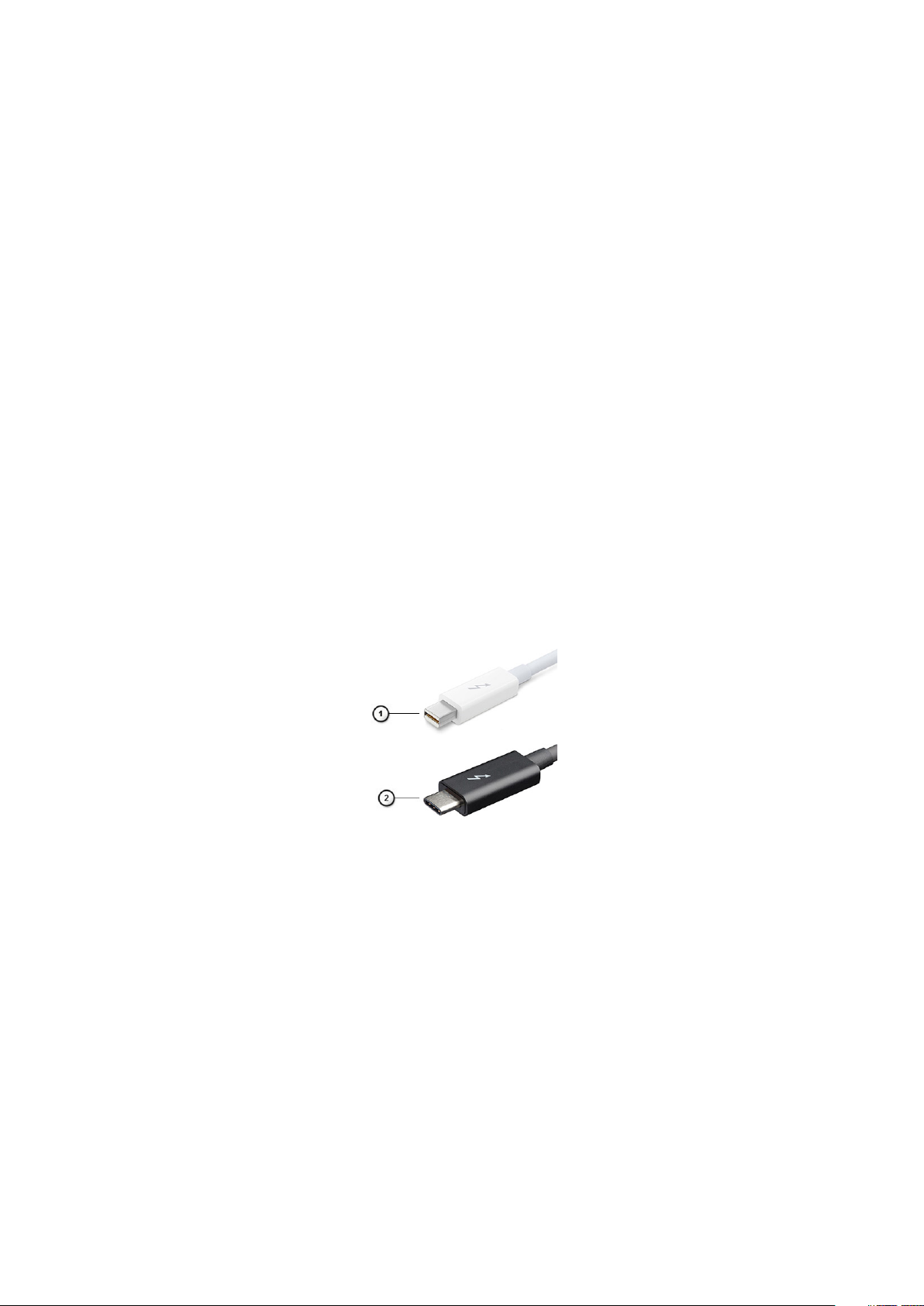
Abbildung 1. Thunderbolt 1 und Thunderbolt 3
1. Thunderbolt 1 und Thunderbolt 2 (miniDP-Stecker)
2. Thunderbolt 3 (USB-Typ-C-Stecker)
Thunderbolt 3 über USB Typ-C
Thunderbolt 3 erhöht über USB Typ-C die Geschwindigkeiten auf bis zu 40 Gbps und bietet alles in einem kompakten Anschluss – die
schnellste, vielseitigste Verbindung mit jedem Dock, Display oder Datengerät, wie einer externen Festplatte. Thunderbolt 3 verwendet
einen USB-Typ-C-Stecker/Port für den Anschluss an unterstützte Peripheriegeräte.
1. Thunderbolt 3 verwendet USB-Typ-C-Stecker und -Kabel. Es ist kompakt und reversibel.
2. Thunderbolt 3 unterstützt Geschwindigkeiten von bis zu 40 Gbps.
3. DisplayPort 1.4 – kompatibel mit vorhandenen DisplayPort-Monitoren, -Geräten und -Kabeln.
4. Stromversorgung über USB – Bis zu 130 W auf unterstützten Computern.
12
Technologie und Komponenten
Page 13
Hauptmerkmale von Thunderbolt 3 über USB Typ-C
1. Thunderbolt, USB, DisplayPort und Stromversorgung über USB-Typ-C in einem einzelnen Kabel (Funktionen können je nach Produkt
variieren).
2. USB-Typ-C-Stecker und -Kabel, die kompakt und reversibel sind.
3. Unterstützt Thunderbolt Networking (*variiert je nach Produkt).
4. Unterstützung für 4 K-Displays.
5. Bis zu 40 Gbps
ANMERKUNG: Datenübertragungsgeschwindigkeiten können je nach Gerät variieren.
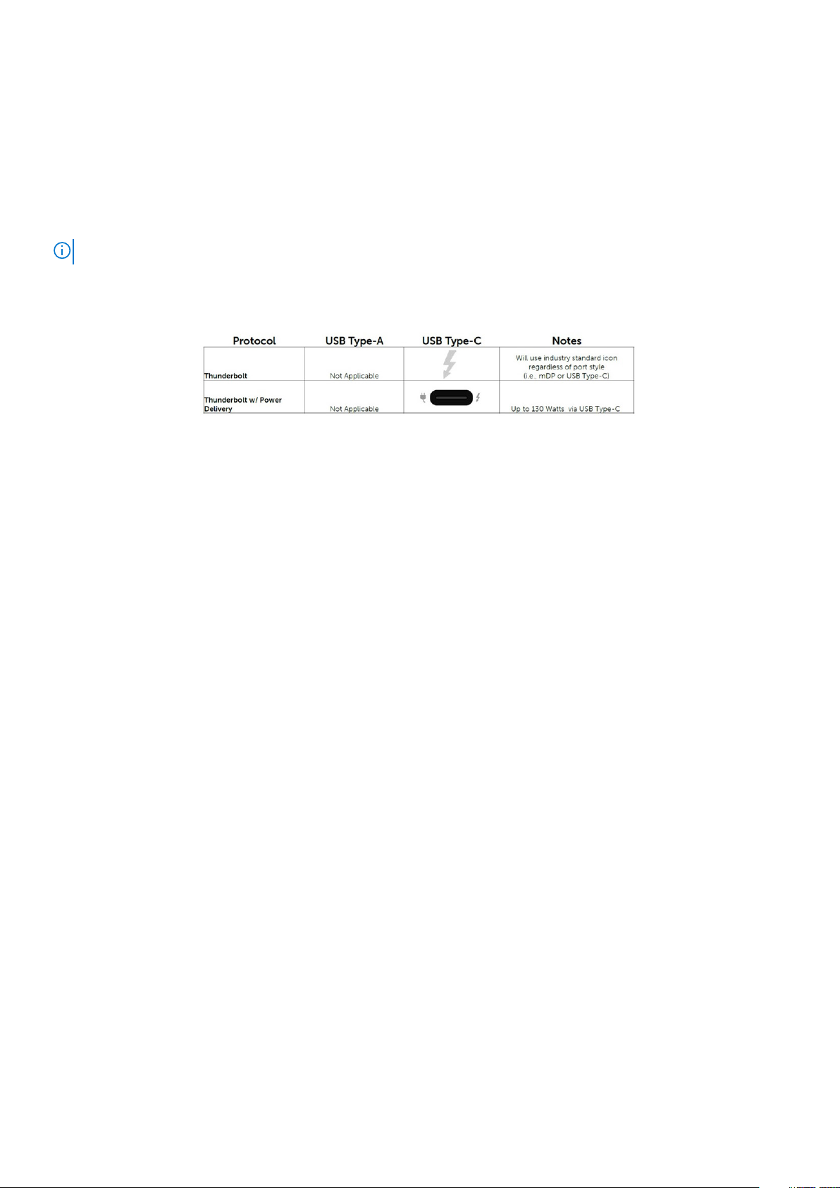
Thunderbolt-Symbole
Abbildung 2. Thunderbolt-Symbolunterschiede
HDMI 2.0
In diesem Abschnitt werden das High-Definition Multimedia Interface (HDMI) 2.0 und seine Funktionen sowie Vorteile erläutert.
HDMI ist eine von der Branche unterstützte, unkomprimierte und vollständig digitale Audio-/Videoschnittstelle. HDMI bietet eine
Schnittstelle zwischen einer kompatiblen digitalen Audio-/Videoquelle, wie z. B. einem DVD-Player oder einem A/V-Receiver und einem
kompatiblen digitalen Audio- und/oder Videobildschirm, wie z. B. einem digitalen TV-Gerät (DTV). HDMI ist für die Verwendung mit
Fernsehgeräten und DVD-Playern vorgesehen. Die Hauptvorteile sind weniger Verkabelungsaufwand und Vorkehrungen zum Schutz von
Inhalten. HDMI unterstützt Standard, Enhanced oder High-Definition Video sowie mehrkanalfähiges Digital-Audio über ein einziges Kabel.
HDMI 2.0-Funktionen
• HDMI-Ethernet-Kanal – Fügt Hochgeschwindigkeits-Netzwerkbetrieb zu einer HDMI-Verbindung hinzu, damit Benutzer ihre IPfähigen Geräte ohne separates Ethernet-Kabel in vollem Umfang nutzen können.
• Audiorückkanal – Ermöglicht einem HDMI-verbundenen Fernseher mit integriertem Tuner, Audiodaten „vorgeschaltet“ an ein
Surround-Audiosystem zu senden, wodurch ein separates Audiokabel überflüssig ist.
• 3D - Definiert Eingabe-/Ausgabeprotokolle für wichtige 3D-Videoformate, was den echten 3D-Spielen und 3D-HeimkinoAnwendungen den Weg ebnet
• Inhaltstyp – Echtzeit-Signalisierung von Inhaltstypen zwischen Anzeige- und Quellgeräten, wodurch ein Fernsehgerät
Bildeinstellungen basierend auf Inhaltstypen optimieren kann.
• Zusätzliche Farbräume – Fügt Unterstützung für weitere Farbmodelle hinzu, die in der Digitalfotografie und Computergrafik
verwendet werden.
• 4K-Unterstützung – Ermöglicht Video-Auflösungen weit über 1080p und unterstützt somit Bildschirme der nächsten Generation,
welche den Digital Cinema-Systemen gleichkommen, die in vielen kommerziellen Kinos verwendet werden.
• HDMI-Mikro-Anschluss - Ein neuer, kleinerer Anschluss für Telefone und andere tragbare Geräte, der Video-Auflösungen bis zu
1080p unterstützt
• Fahrzeug-Anschlusssystem – Neue Kabel und Anschlüsse für Fahrzeug-Videosysteme, die speziell für die einzigartigen
Anforderungen des Fahrumfeldes entworfen wurden und gleichzeitig echte HD-Qualität liefern.
Vorteile von HDMI
• Qualitäts-HDMI überträgt unkomprimiertes digitales Audio und Video bei höchster, gestochen scharfer Bildqualität.
• Kostengünstige HDMI bietet die Qualität und Funktionalität einer digitalen Schnittstelle, während sie auch unkomprimierte
Videoformate in einer einfachen, kosteneffektiven Weise unterstützt.
• Audio-HDMI unterstützt mehrere Audioformate, von Standard-Stereo bis hin zu mehrkanaligem Surround-Sound
Technologie und Komponenten
13
Page 14
• HDMI kombiniert Video und Mehrkanalaudio in einem einzigen Kabel, wodurch Kosten, Komplexität und das Durcheinander von
mehreren Kabeln, die derzeit in AV-Systemen verwendet werden, wegfallen.
• HDMI unterstützt die Kommunikation zwischen der Videoquelle (wie z. B. einem DVD-Player) und dem DTV, und ermöglicht dadurch
neue Funktionen.
NVIDIA Quadro T1000
Tabelle 2. NVIDIA Quadro T1000
Funktion Werte
Grafikspeicher 4 GB
Kerne 768
Speicherbandbreite 128 Gbit/s
Arbeitsspeichertyp GDDR6
Speicherschnittstelle 128 Bit
Taktraten 1395 bis 1455 (Boost) MHz
GPU-Basistakt 8000 MHz (min. bei P0)
Geschätzte Maximalleistung 50 W
Displaysupport eDP/mDP/HDMI/Typ C
Maximale Farbtiefe Bis zu 10 Bit/Farbe
Betriebssystemgrafik/Video-API-Unterstützung DirectX 12.0, OpenGL 4.6, DisplayPort 1.4, DirectX 12.1
Unterstützte Auflösungen und maximale Bildwiederholfrequenzen
(Hz)
Anzahl der unterstützten Bildschirme Bis zu 4 Monitore
• Max. digital: Einzelner DisplayPort 1.4 – 7680 x 4320 (8K) bei
30 Hz (mDP/Typ C zu DP)
• Max. digital: Zwei DisplayPort 1.4-Anschlüsse – 7680 x 4320
(8K) bei 60 Hz (mDP/Typ C zu DP)
NVIDIA Quadro RTX3000
Tabelle 3. NVIDIA Quadro RTX3000
Funktion Werte
Grafikspeicher 6 GB
Kerne 2304
Speicherbandbreite 336 Gbit/s
Arbeitsspeichertyp GDDR6
Speicherschnittstelle 192-Bit
Taktraten 945 bis 1380 (Boost) MHz
GPU-Basistakt 3504 MHz (min. bei P0)
Geschätzte Maximalleistung 80 W
Displaysupport eDP/mDP/HDMI/Typ C
Maximale Farbtiefe Bis zu 10 Bit/Farbe
Betriebssystemgrafik/Video-API-Unterstützung DirectX 12.0, OpenGL 4.6, DisplayPort 1.4, DirectX 12.1
14 Technologie und Komponenten
Page 15
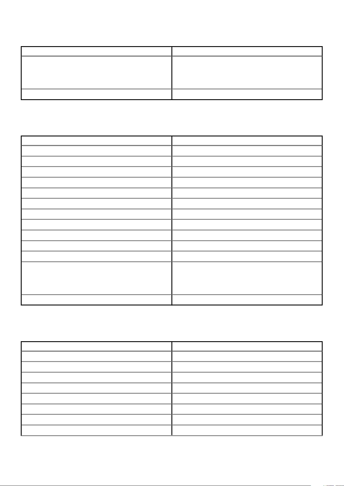
Tabelle 3. NVIDIA Quadro RTX3000(fortgesetzt)
Funktion Werte
Unterstützte Auflösungen und maximale Bildwiederholfrequenzen
(Hz)
Anzahl der unterstützten Bildschirme Bis zu 4 Monitore
• Max. digital: Einzelner DisplayPort 1.4 – 7680 x 4320 (8K) bei
30 Hz (mDP/Typ C zu DP)
• Max. digital: Zwei DisplayPort 1.4-Anschlüsse – 7680 x 4320
(8K) bei 60 Hz (mDP/Typ C zu DP)
NVIDIA Quadro RTX4000
Table 4. NVIDIA Quadro RTX4000
Feature Values
Graphics memory 8 GB
Cores 2560
Memory bandwidth 448 Gbps
Memory type GDDR6
Memory Interface 256-bit
Clock Speeds 1110 - 1560 (Boost) MHz
GPU base clock 14000 MHz
Estimated Maximum Power 100 W
Display Support eDP/mDP/HDMI/Type-C
Maximum Color Depth Up to 10 bit/color
Operating Systems Graphics/ Video API Support DirectX 12.0, OpenGL 4.6, DisplayPort 1.4, DirectX 12.1
Supported Resolutions and Max Refresh Rates (Hz)
Numbers of Display Support Up to 4 displays
• Max Digital : Single DisplayPort 1.4 - 7680 x 4320 (8k) @ 30 Hz
(mDP/Type-c to DP)
• Max Digital : Dual DisplayPort 1.4 - 7680 x 4320 (8k) @ 60 Hz
(mDP/Type-c to DP)
NVIDIA Quadro RTX5000
Table 5. NVIDIA Quadro RTX5000
Feature Values
Graphics memory 16 GB
Cores 3072
Memory bandwidth 448 Gbps
Memory type GDDR6
Memory Interface 256-bit
Clock Speeds 1035 / 1350 - 1545 / 1770 (Boost) MHz
GPU base clock 14000 MHz
Estimated Maximum Power 110 W
Technologie und Komponenten 15
Page 16

Table 5. NVIDIA Quadro RTX5000(continued)
Feature Values
Display Support eDP/mDP/HDMI/Type-C
Maximum Color Depth Up to 10 bit/color
Operating Systems Graphics/ Video API Support DirectX 12.0, OpenGL 4.6, DisplayPort 1.4, DirectX 12.1
Supported Resolutions and Max Refresh Rates (Hz)
Numbers of Display Support Up to 4 displays
• Max Digital : Single DisplayPort 1.4 - 7680 x 4320 (8k) @ 30 Hz
(mDP/Type-C to DP)
• Max Digital : Dual DisplayPort 1.4 - 7680 x 4320 (8k) @ 60 Hz
(mDP/Type-C to DP)
16 Technologie und Komponenten
Page 17

Ausbau und Wiedereinbau
SD-Karte
Entfernen der SD-Karte
Voraussetzungen
1. Folgen Sie den Anweisungen unter Vor der Arbeit an Komponenten im Inneren des Computers.
Info über diese Aufgabe
Die Abbildung zeigt die Position der SD-Karte und bietet eine visuelle Darstellung des Verfahrens zum Entfernen. Bilder werden im
nächsten Prüfzyklus hochgeladen.
Schritte
1. Drücken Sie auf die SD-Karte, um sie vom Computer zu lösen.
2. Ziehen Sie die SD-Karte aus dem Computer heraus.
3
Installieren der SD-Karte
Voraussetzungen
Wenn Sie eine Komponente austauschen, muss die vorhandene Komponente entfernt werden, bevor Sie das Installationsverfahren
durchführen.
Info über diese Aufgabe
Die Abbildung zeigt die Position der Bodenabdeckung und bietet eine visuelle Darstellung des Installationsverfahrens.
Bilder werden im nächsten Prüfzyklus hochgeladen
Schritte
Setzen Sie die SD-Karte in den Steckplatz im Computer ein, bis sie einrastet.
Nächste Schritte
1. Folgen Sie den Anweisungen unter Nach der Arbeit an Komponenten im Inneren des Computers.
SSD-Zugangsklappe
Removing SSD door
Prerequisites
1. Follow the procedure in before working inside your computer.
2. Remove the SD card.
Ausbau und Wiedereinbau 17
Page 18

About this task
The figure indicates the location of the SSD door reader and provides a visual representation of the removal procedure.
Steps
1. Push the SSD door towards left side to release the SSD door from the base cover.
2. Remove the SSD door from the base cover.
Installing SSD door
Prerequisites
If you are replacing a component, remove the existing component before performing the installation procedure.
About this task
The figure indicates the location of the SSD door and provides a visual representation of the installation procedure.
18
Ausbau und Wiedereinbau
Page 19
Steps
1. Place the SSD door into its slot on the base cover.
2. Push the SSD door towards right side to lock the SSD door.
Next steps
1. Install the SD card.
2. Follow the procedure in after working inside your computer.
Sekundäres M.2 SSD-Laufwerk
Removing the secondary M.2 Solid-state drive
Prerequisites
NOTE: For computers shipped with M.2 2280 or 2230 SSD installed in slot 6.
1. Follow the procedure in before working inside your computer.
2. Remove the SD card.
3. Remove the SSD door.
About this task
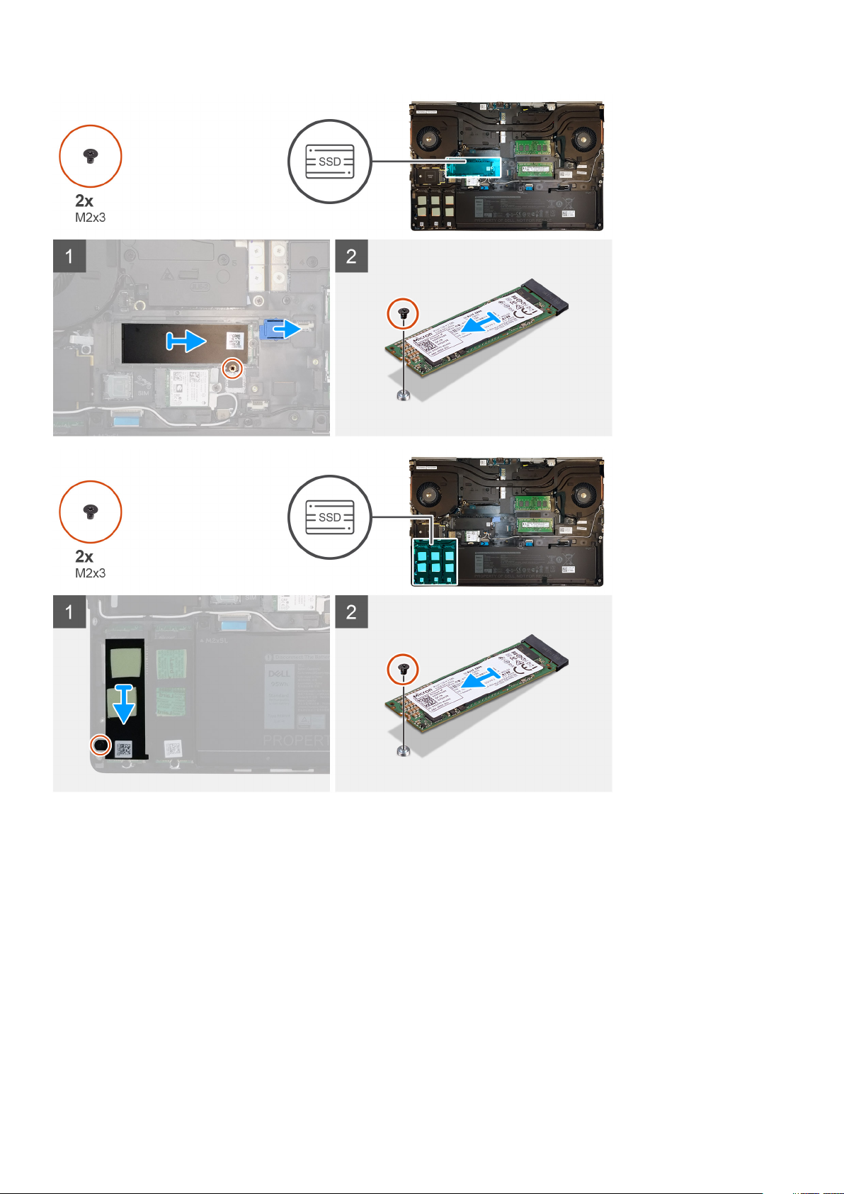
The figure indicates the location of the secondary M.2 SSD and provides a visual representation of the removal procedure.
Ausbau und Wiedereinbau
19
Page 20
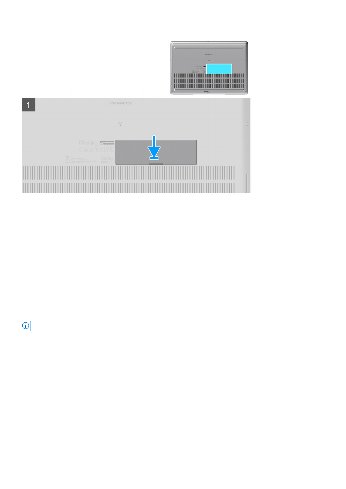
Steps
1. Slide the SSD release latch to unlock the SSD module.
2. Remove the (M2x3) screw that secures the SSD module into its slot on the computer.
3. Remove the SSD module from the computer.
4. Remove the (M2x3) screw that secures the SSD thermal pad to the SSD carrier.
5. Remove the SSD thermal pad from the SSD module.
6. For M.2 2280 SSD:
a. Remove the M.2 2280 SSD from the SSD carrier.
7. For M.2 2230 SSD:
a. Remove the M.2 2230 SSD with its holder from the SSD carrier.
b. Remove the (M2x2) screw to secure the M.2 2230 SSD to its holder.
c. Remove the SSD from the holder.
Installing the secondary M.2 SSD module
Prerequisites
NOTE: For computers shipped with M.2 2280 or 2230 SSD installed in slot 6.
If you are replacing a component, remove the existing component before performing the installation procedure.
About this task
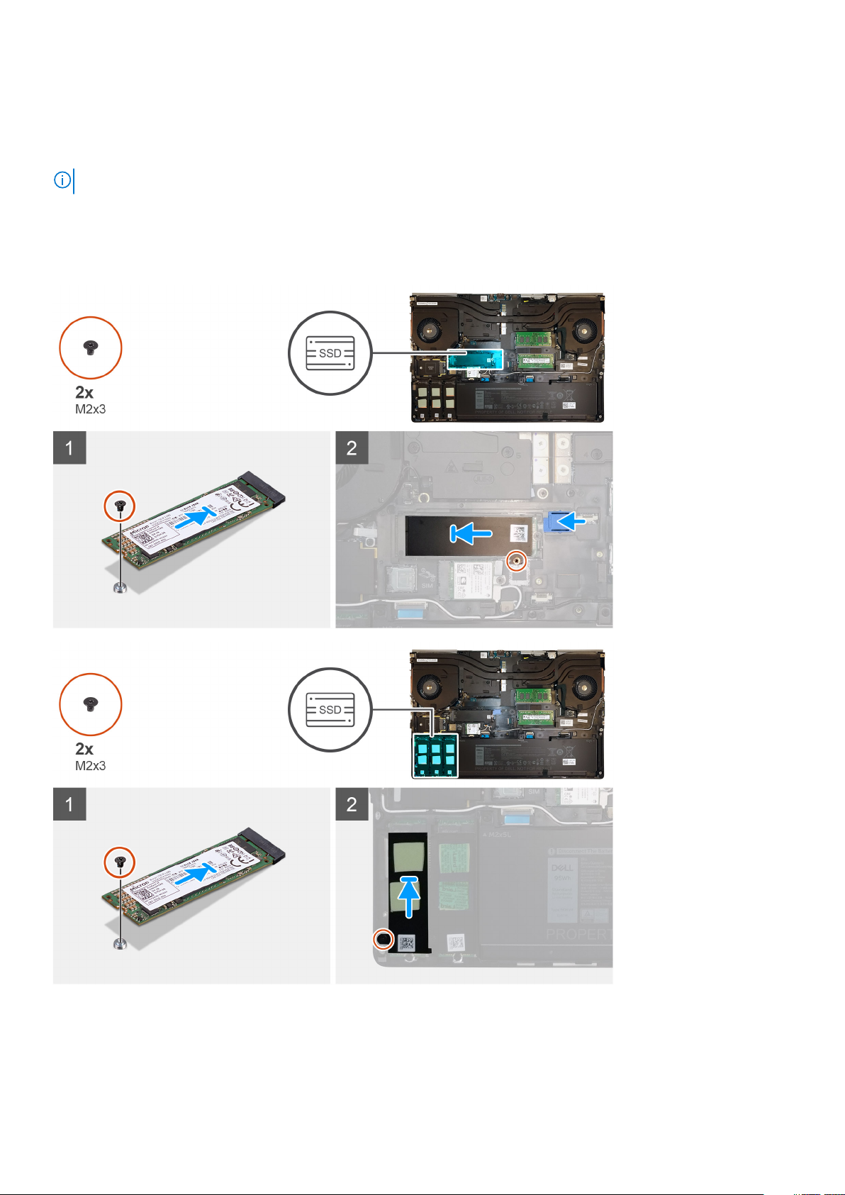
The figure indicates the location of the secondary M.2 SSD and provides a visual representation of the installation procedure.
20
Ausbau und Wiedereinbau
Page 21
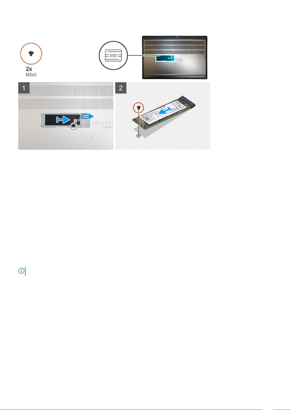
Steps
1. For M.2 2280 SSD:
a. Place the M.2 SSD onto its slot on SSD carrier.
2. For M.2 2230 SSD:
a. Place the M.2 SSD into the SSD holder.
b. Replace the (M2x2) screw to secure the M.2 SSD to the holder.
c. Place the M.2 SSD with its holder on the SSD carrier.
3. Place the thermal plate above the M.2 SSD module.
4. Replace the (M2x3) screw to secure the SSD thermal plate to the M.2 SSD.
5. Replace the SSD module in its slot on the computer.
6. Replace the (M2x3) screw to secure the SSD module in place.
Next steps
1. Install the SSD door.
2. Install the SD card.
3. Follow the procedure in after working inside your computer.
Bodenabdeckung
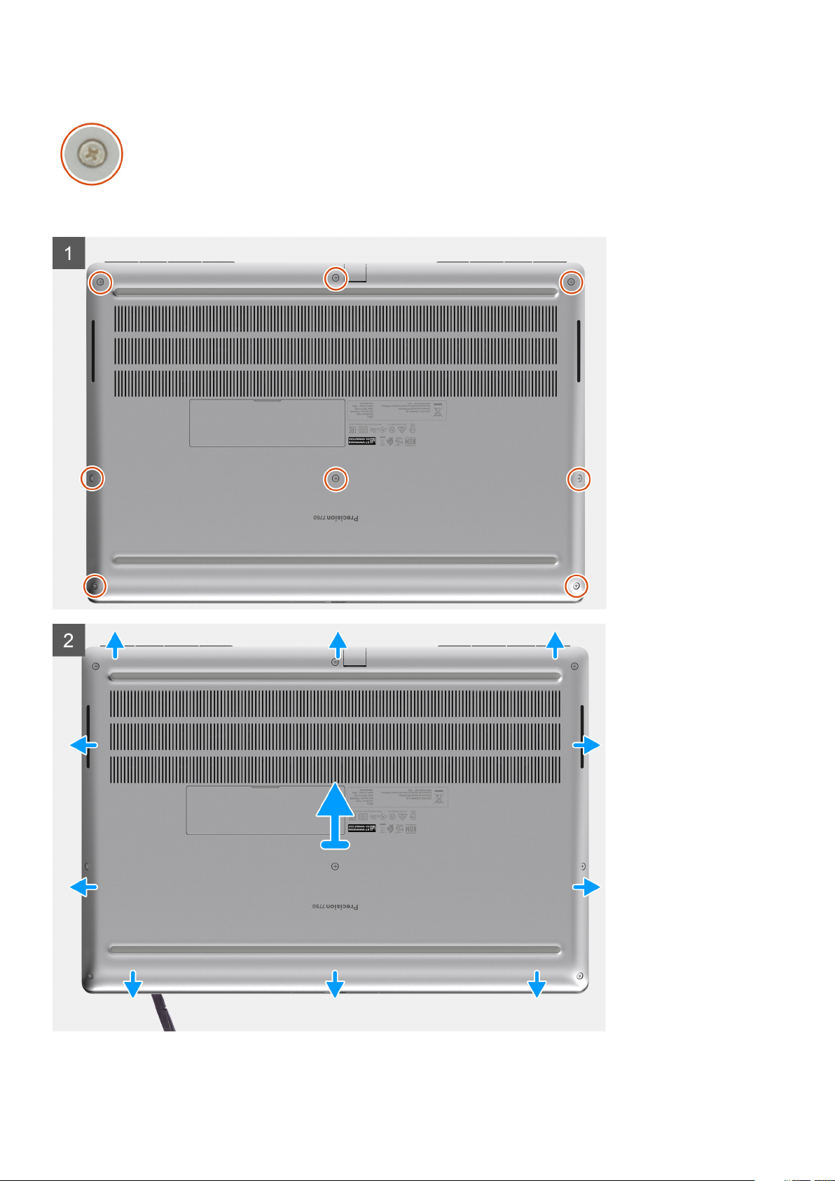
Removing the base cover
Prerequisites
1. Follow the procedure in before working inside your computer.
2. Remove the SD card.
About this task
The figure indicates the location of the base cover and provides a visual representation of the removal procedure
Ausbau und Wiedereinbau
21
Page 22
22 Ausbau und Wiedereinbau
Page 23
Steps
1. Loosen the eight captive screws that secure the base cover to the computer.
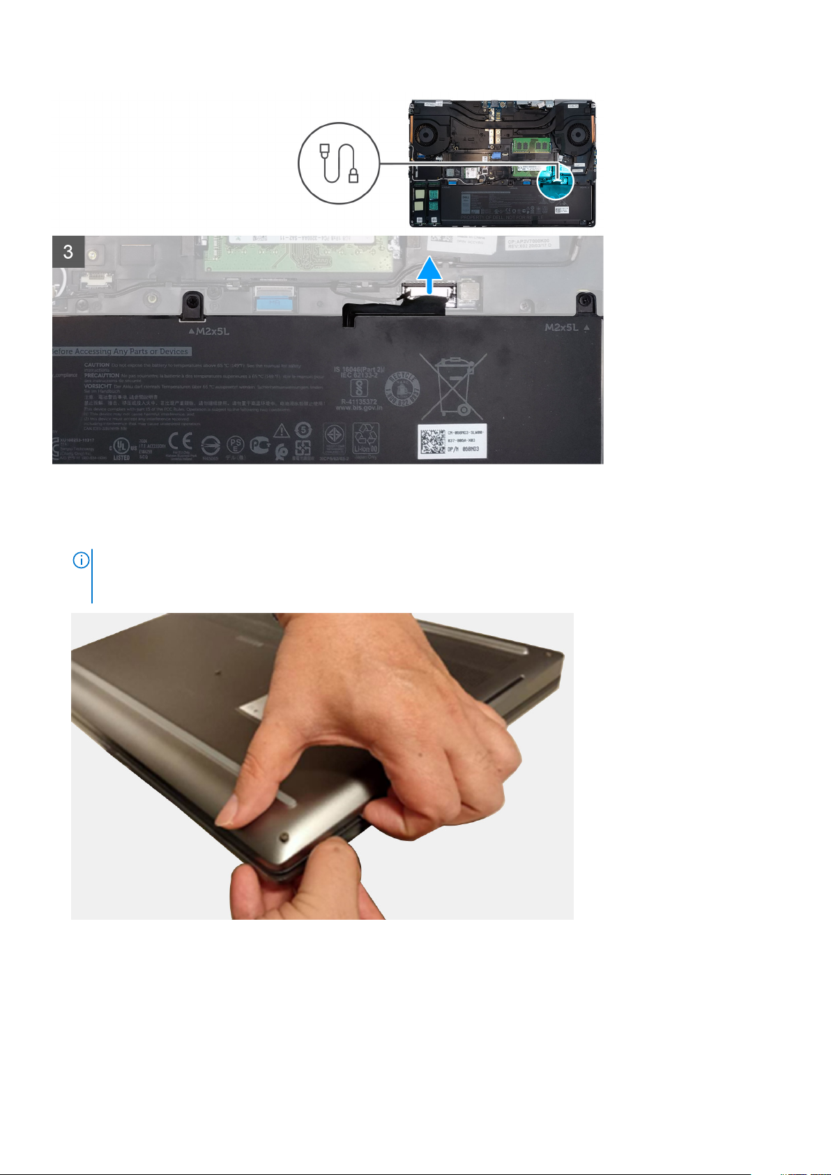
2. Using a plastic scribe, pry open the base cover starting from bottom edge of the cover.
NOTE:
For models shipped without SmartCard reader, pry open the base cover from the smart card reader slot. Use
your fingers to pry open the base cover as the use of plastic scribe or any other sharp objects may damage the base
cover.
Ausbau und Wiedereinbau 23
Page 24
3. Lift the base cover starting from the bottom edge and remove it from the computer.
4. Disconnect the battery cable from the connector on the system board.
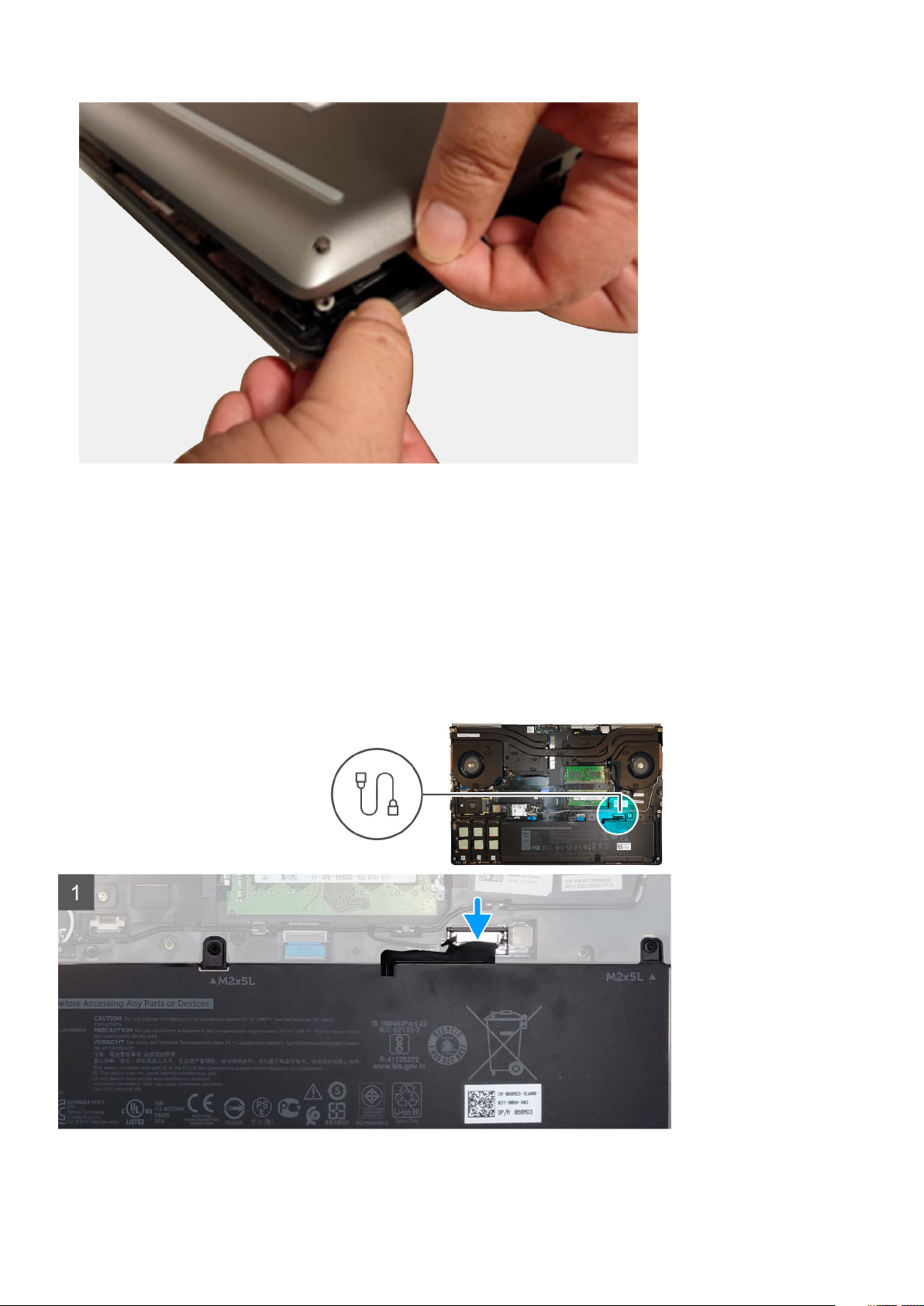
Installing the base cover
Prerequisites
If you are replacing a component, remove the existing component before performing the installation procedure.
About this task
The figure indicates the location of the base cover and provides a visual representation of the installation procedure.
24
Ausbau und Wiedereinbau
Page 25
Ausbau und Wiedereinbau 25
Page 26

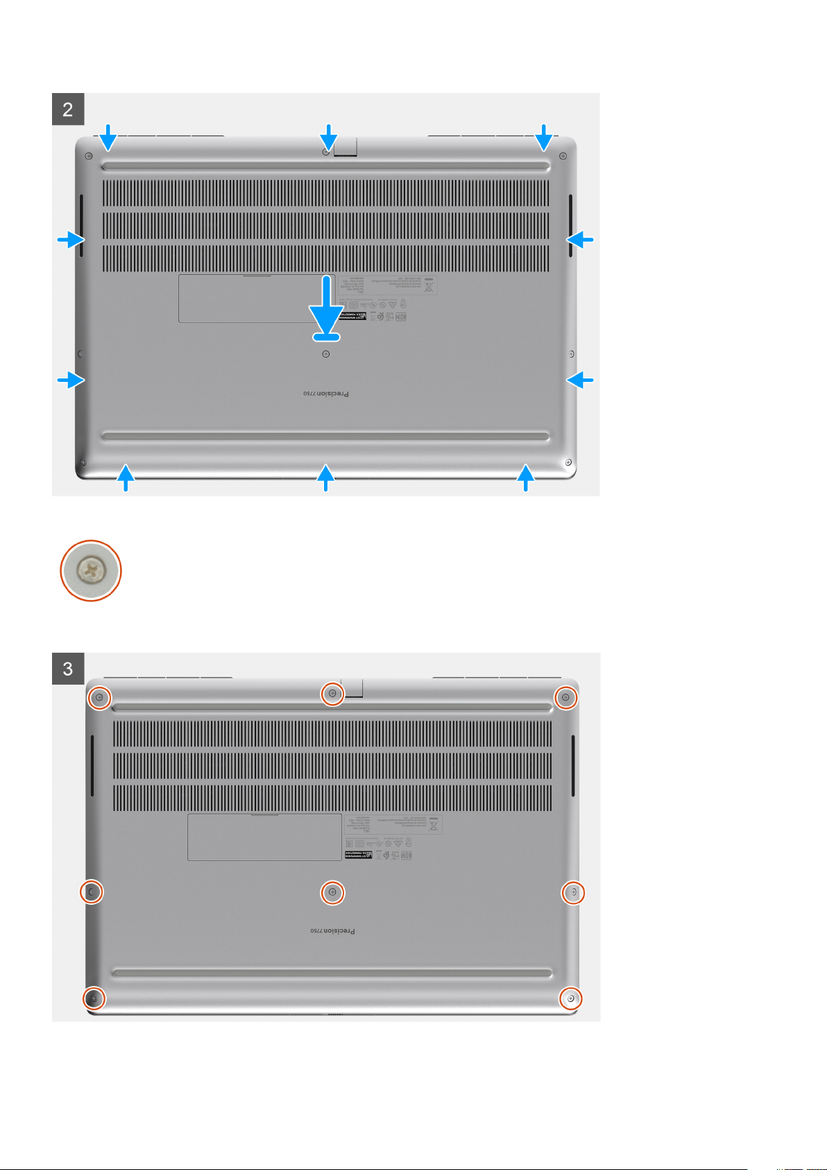
Steps
1. Connect the battery cable to the connector on the system board.
2. Slide the base cover into its slot until it clicks into place.
3. Tighten the eight captive screws to secure the base cover to the computer.
Next steps
1. Install the SD card.
2. Follow the procedure in after working inside your computer.
Akku
Vorsichtshinweise zu Lithium-Ionen-Akkus
VORSICHT:
• Seien Sie vorsichtig beim Umgang mit Lithium-Ionen-Akkus.
• Entladen Sie die Batterie möglichst weit, bevor Sie sie aus dem System entfernen. Hierzu können Sie den
Netzadapter vom System trennen, damit die Batterie entladen kann.
• Düben Sie keinen Druck auf den Akkus aus, lassen Sie ihn nicht fallen, beschädigen Sie ihn nicht und führen Sie keine
Fremdkörper ein.
• Setzen Sie den Akku keinen hohen Temperaturen aus und bauen Sie Akkus und Akkuzellen nicht auseinander.
• Üben Sie keinen Druck auf die Oberfläche des Akkus aus.
• Biegen Sie den Akku nicht.
• Verwenden Sie keine Werkzeuge, um die Batterie herauszuhebeln.
• Stellen Sie sicher, dass bei der Wartung dieses Produkts sämtliche Schrauben wieder angebracht werden, da
andernfalls die Batterie und andere Systemkomponenten versehentlich durchstochen oder anderweitig beschädigt
werden können.
• Wenn sich eine Batterie aufbläht und in Ihrem Computer stecken bleibt, versuchen Sie nicht, sie zu lösen, da das
Durchstechen, Biegen oder Zerdrücken einer Lithium-Ionen-Batterie gefährlich sein kann. Wenden Sie sich in einem
solchen Fall an den technischen Support von Dell. Siehe www.dell.com/contactdell.
• Erwerben Sie ausschließlich original Batterien von www.dell.com oder autorisierten Dell Partnern und
Wiederverkäufern.
Removing the battery
Prerequisites
1. Follow the procedure in before working inside your computer.
2. Remove the SD card.
3. Remove the base cover.
About this task
The figure indicates the location of the battery and provides a visual representation of the removal procedure.
26
Ausbau und Wiedereinbau
Page 27
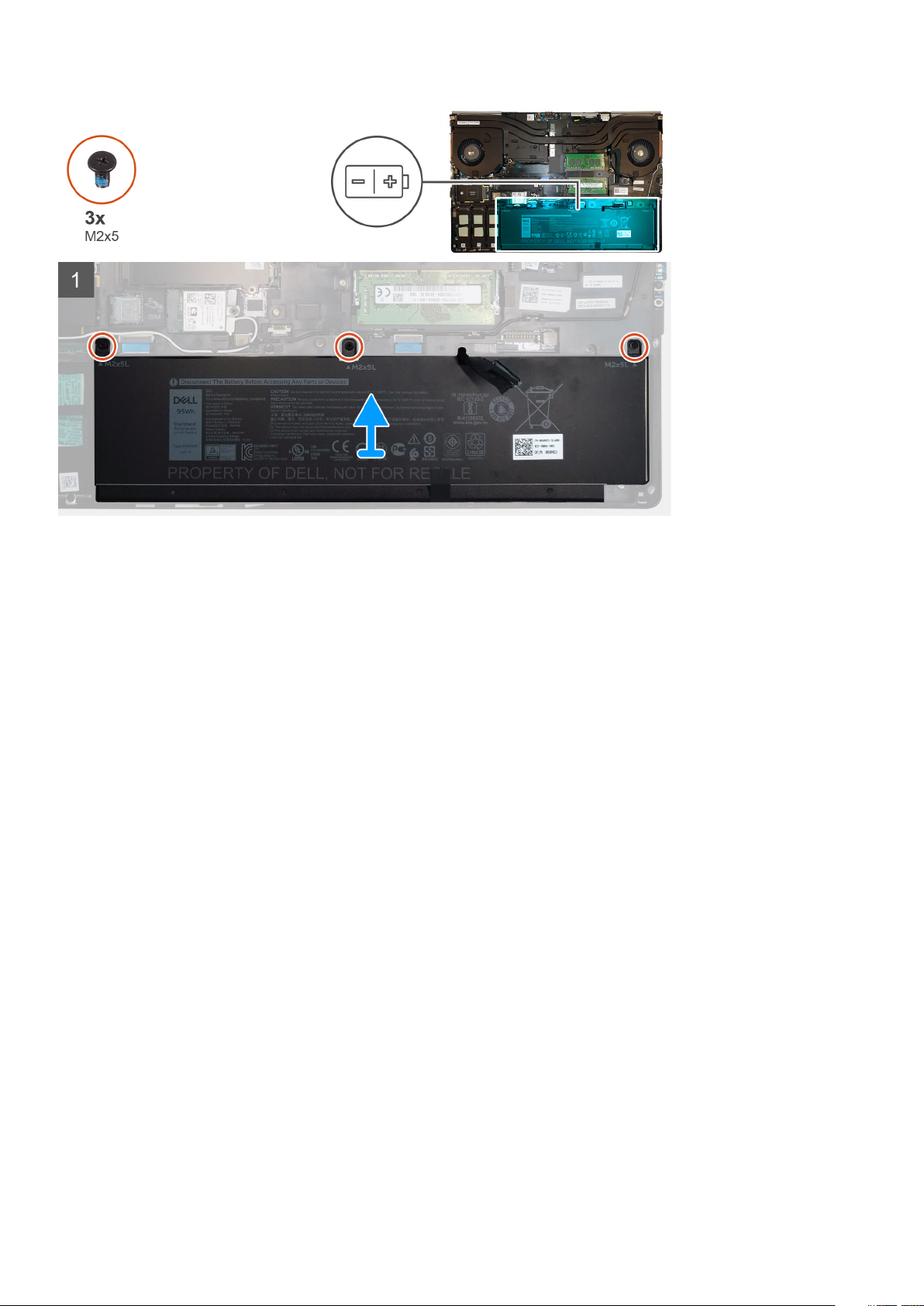
Steps
1. Remove the three (M2x5) screws that secure the battery to the computer.
2. Slightly lift the battery and disconnect the battery cable from the connector on the battery.
3. Remove the battery away from the computer.
Installing the battery
Prerequisites
If you are replacing a component, remove the existing component before performing the installation procedure.
About this task
The figure indicates the location of the battery and provides a visual representation of the installation procedure.
Ausbau und Wiedereinbau
27
Page 28

Steps
1. Connect the battery cable to the connector in the battery.
2. Place the battery onto its slot in the computer.
3. Replace the three (M2x5) screws to secure the battery to the computer.
Next steps
1. Install the base cover.
2. Install the SD card.
3. Follow the procedure in after working inside your computer.
SSD-Laufwerk
Removing the primary M.2 Solid-state drive
Prerequisites
NOTE: For computers shipped with M.2 2280 or 2230 SSD installed in slot 3, slot 4, and/or slot 5.
1. Follow the procedure in before working inside your computer.
2. Remove the SD card.
3. Remove the base cover.
About this task
The figure indicates the location of the primary M.2 SSD and provides a visual representation of the removal procedure.
28
Ausbau und Wiedereinbau
Page 29
Steps
1. Remove the (M2x3) screw that secures the SSD thermal plate to the M.2 SSD module.
2. Remove the SSD thermal plate.
3. For M.2 2280 SSD:
a. Remove the (M2x3) screw that secures the M.2 SSD to the computer.
b. Remove the M.2 SSD.
4. For M.2 2230 SSD:
a. Remove the (M2x3) screw that secures the SSD module.
b. Remove the SSD module from the computer.
c. Remove the (M2x2) screw that secures the SSD to SSD holder.
d. Remove the SSD from the holder.
5. Repeat the above steps to remove the other SSD modules in the computer.
Ausbau und Wiedereinbau
29
Page 30
Installing the primary M.2 SSD module
Prerequisites
NOTE: For computers shipped with M.2 2280 or 2230 SSD installed in slot 3, slot 4, and/or slot 5.
If you are replacing a component, remove the existing component before performing the installation procedure.
About this task
The figure indicates the location of the primary M.2 SSD and provides a visual representation of the installation procedure.
Steps
1. For M.2 2280 SSD:
a. Place the M.2 SSD onto its slot on the computer.
b. Replace the (M2x3) screw to secure the M.2 SSD to the computer.
30
Ausbau und Wiedereinbau
Page 31

2. For M.2 2230 SSD:
a. Place the M.2 SSD into the SSD holder.
b. Replace the (M2x2) screw to secure the M.2 SSD to the holder.
c. Place the M.2 SSD module onto its slot on the computer.
d. Replace the (M2x3) screw to secure the M.2 SSD module to the computer.
3. Place the thermal plate above the M.2 SSD module.
4. Replace the (M2x3) screw to secure the SSD thermal plate to the M.2 SSD.
5. Repeat the above steps to install the other SSD modules in the computer.
Next steps
1. Install the base cover.
2. Install the SD card.
3. Follow the procedure in after working inside your computer.
Sekundäres Speichermodul
Removing the secondary memory module
Prerequisites
1. Follow the procedure in before working inside your computer.
2. Remove the SD card.
3. Remove the base cover.
About this task
The figure indicates the location of the secondary memory module and provides a visual representation of the removal procedure.
Steps
1. Pry the securing clips from both side of the memory module until the memory module pops up.
2. Remove the memory module from the memory-module slot.
Ausbau und Wiedereinbau
31
Page 32

Installing the secondary memory module
Prerequisites
If you are replacing a component, remove the existing component before performing the installation procedure.
About this task
The figure indicates the location of the secondary and provides a visual representation of the installation procedure.
Steps
1. Align the notch on the memory module with the tab on the memory-module slot.
2. Slide the memory module firmly into the slot and press the memory module until it clicks into place.
NOTE: If you do not hear the click, remove the memory module and reinstall it.
Next steps
1. Install the base cover.
2. Install the SD card.
3. Follow the procedure in after working inside your computer.
SIM-Karte
Removing the SIM card
Prerequisites
1. Follow the procedure in before working inside your computer.
2. Remove the SD card.
3. Remove the base cover.
About this task
The figure indicates the location of the SIM card and provides a visual representation of the removal procedure.
32
Ausbau und Wiedereinbau
Page 33

Steps
1. Gently slide the SIM card cover towards the left side of the system to unlock the SIM card cover.
CAUTION: The SIM card cover is very fragile and can be easily damaged if it is not properly unlocked before opening.
2. Filp the right edge of the SIM card cover to open it.
3. Remove the SIM card from the SIM card slot.
Installing the SIM card
Prerequisites
If you are replacing a component, remove the existing component before performing the installation procedure.
About this task
The figure indicates the location of the SIM card and provides a visual representation of the installation procedure.
Ausbau und Wiedereinbau
33
Page 34

Steps
1. Slide the SIM card into the SIM card slot.
2. Snap the SIM card cover down.
3. Slide the SIM card cover towards the right of the system to lock the cover.
Next steps
1. Install the base cover.
2. Install the SD card.
3. Follow the procedure in after working inside your computer.
WLAN-Karte
Removing the WLAN card
Prerequisites
1. Follow the procedure in before working inside your computer.
2. Remove the SD card.
3. Remove the base cover.
About this task
The figure indicates the location of the WLAN card and provides a visual representation of the removal procedure.
34
Ausbau und Wiedereinbau
Page 35

Steps
1. Loosen the captive screw that secures the WLAN card bracket to the system board.
2. Remove the WLAN card bracket away from the WLAN card.
3. Disconnect the antenna cables from the WLAN card.
4. Slide at an angle and remove the WLAN card from the connector on the system board.
Installing the WLAN card
Prerequisites
If you are replacing a component, remove the existing component before performing the installation procedure.
About this task
The figure indicates the location of the WLAN card and provides a visual representation of the installation procedure.
Steps
1. Insert the WLAN card to the connector on the system board.
2. Connect the antenna cables to the WLAN card.
3. Align and place the WLAN card bracket above the WLAN card to secure the antenna cables.
4. Tighten the captive screw to secure the WLAN card bracket to the system board.
Next steps
1. Install the base cover.
Ausbau und Wiedereinbau
35
Page 36

2. Install the SD card.
3. Follow the procedure in after working inside your computer.
WWAN-Karte
Removing the WWAN card
Prerequisites
1. Follow the procedure in before working inside your computer.
2. Remove the SD card.
3. Remove the base cover.
About this task
The figure indicates the location of the WWAN card and provides a visual representation of the removal procedure.
Steps
1. Loosen the (M2x3) screw that secures the WWAN card bracket to the system board.
2. Lift the WWAN card bracket from the WWAN card.
3. Disconnect the antenna cables from the connector on the WWAN card.
4. Slide and remove the WWAN card from its slot on the system board.
Installing the WWAN card
Prerequisites
If you are replacing a component, remove the existing component before performing the installation procedure.
About this task
The figure indicates the location of the WWAN card and provides a visual representation of the installation procedure.
Steps
1. Align and slide the WWAN card to its slot on the system board.
36
Ausbau und Wiedereinbau
Page 37

2. Connect the antenna cables to the connectors on the WWAN card.
3. Place the WWAN card bracket above the WWAN card to secure the antenna cables.
4. Tighten the (M2x3) screw to secure the WWAN card bracket to the system board.
Next steps
1. Install the base cover.
2. Install the SD card.
3. Follow the procedure in after working inside your computer.
Tastaturgitter
Removing the keyboard lattice
Prerequisites
1. Follow the procedure in before working inside your computer.
2. Remove the SD card.
3. Remove the base cover.
About this task
The figure indicates the location of the keyboard lattice and provides a visual representation of the removal procedure.
Steps
1. Using a plastic scribe, pry the top edge of the keyboard lattice starting from the recess points and working your way around the sides
and bottom edge.
2. Remove the keyboard lattice from the keyboard.
Ausbau und Wiedereinbau
37
Page 38

Installing the keyboard lattice
Prerequisites
If you are replacing a component, remove the existing component before performing the installation procedure.
About this task
The figure indicates the location of the M.2 SSD and provides a visual representation of the installation procedure.
Steps
1. Align the keyboard lattice to its position on the keyboard.
2. Press the edges on the keyboard lattice until it clicks into place.
Next steps
1. Install the base cover.
2. Install the SD card.
3. Follow the procedure in after working inside your computer.
Tastatur
Removing the keyboard
Prerequisites
1. Follow the procedure in before working inside your computer.
2. Remove the SD card.
3. Remove the base cover.
4. Remove the battery.
5. Remove the keyboard lattice.
38
Ausbau und Wiedereinbau
Page 39

About this task
The figure indicates the location of the keyboard and provides a visual representation of the removal procedure.
Steps
1. Lift the latch and disconnect the keyboard cable and the keyboard backlight cable from the connectors on the touchpad module.
2. Turn-over and open the system at 90° angle.
3. Remove the six (M2x2.5) screws that secure the keyboard to the palmrest.
4. Pry the bottom edge of the keyboard and then work along the left and the right sides of the keyboard.
5. Carefully unroute the keyboard backlight cable and the keyboard cable through the palmrest.
6. Remove the keyboard from the system.
Installing the keyboard
Prerequisites
If you are replacing a component, remove the existing component before performing the installation procedure.
About this task
The figure indicates the location of the keyboard and provides a visual representation of the installation procedure.
Ausbau und Wiedereinbau
39
Page 40

Steps
1. Align the keyboard to its slot on the palmrest
2. Route the keyboard cable and the keyboard backlight cable through the bottom of the palmrest.
3. Replace the six (M2x2.5) screws to secure the keyboard to the palmrest.
4. Turn-over the system at 90° angle to access the keyboard and the keyboard backlight cables.
5. Connect the keyboard backlight cable and the keyboard cable to the connectors on the system board.
NOTE: Ensure that you fold the keyboard data cable in perfect alignment.
Next steps
1. Install the keyboard lattice.
2. Install the battery.
3. Install the base cover.
4. Install the SD card.
5. Follow the procedure in after working inside your computer.
40
Ausbau und Wiedereinbau
Page 41

Primäres Speichermodul
Removing the primary memory module
Prerequisites
1. Follow the procedure in before working inside your computer.
2. Remove the SD card.
3. Remove the base cover.
4. Remove the battery.
5. Remove the keyboard lattice.
6. Remove the keyboard.
About this task
The figure indicates the location of the primary memory module and provides a visual representation of the removal procedure.
Steps
1. Remove the (M2x3) screw that secures the memory shield in place.
Ausbau und Wiedereinbau
41
Page 42

2. Slide the memory shield towards the right side of the computer and lift the shield from the memory module.
3. Pry the securing clips from both side of the memory module until the memory module pops up.
4. Remove the memory module from the memory-module slot.
NOTE: Repeat the above steps if there are other memory installed.
Installing the primary memory module
Prerequisites
If you are replacing a component, remove the existing component before performing the installation procedure.
About this task
The figure indicates the location of the primary memory module and provides a visual representation of the installation procedure.
Steps
1. Align the notch on the memory module with the tab on the memory-module slot.
2. Slide the memory module firmly into the slot at an angle and press the memory module down until it clicks into place.
3. Carefully align the two clips on the memory shield with the slots on the computer chassis and insert the clips under the chassis.
42
Ausbau und Wiedereinbau
Page 43

4. Place the memory shield and slide it towards the left side of the computer to cover the memory module.
5. Replace the (M2x3) screw to secure the memory shield to the memory module.
Next steps
1. Install the keyboard.
2. Install the keyboard lattice.
3. Install the battery.
4. Install the base cover.
5. Install the SD card.
6. Follow the procedure in after working inside your computer.
Kühlkörper
Removing the heat-sink assembly
Prerequisites
1. Follow the procedure in before working inside your computer.
2. Remove the SD card.
3. Remove the base cover.
4. Remove the battery.
About this task
The figure indicates the location of the heat-sink assembly and provides a visual representation of the removal procedure.
Steps
1. Peel the power-adapter cable from the heat-sink assembly.
2. Disconnect the two fan cables from the connectors on the system board.
3. Loosen the eight captive screws that secure the heat-sink assembly to the system board.
Loosen the captive screws in the order stamped onto the heat-sink assembly next to the screws [1 > 2 > 3 > 4
NOTE:
> 5 > 6 > 7 > 8].
Ausbau und Wiedereinbau 43
Page 44

4. Lift the heat-sink assembly to remove it from the computer.
Installing the heat sink assembly
Prerequisites
If you are replacing a component, remove the existing component before performing the installation procedure.
About this task
The figure indicates the location of the keyboard and provides a visual representation of the installation procedure.
Steps
1. Align and insert the heat-sink assembly into its slot on the computer.
2. Tighten the eight captive screws to secure the heat-sink assembly to the system board.
NOTE:
Tighten the captive screws in the order stamped onto the heat sink next to the screws [1 > 2 > 3 > 4 > 5 > 6 >
7 > 8].
3. Connect the two fan cables to the connector on the system board.
4. Adhere the power-adapter cable on the heat-sink assembly.
Next steps
1. Install the battery.
2. Install the base cover.
3. Install the SD card.
4. Follow the procedure in after working inside your computer.
44
Ausbau und Wiedereinbau
Page 45

Netzadapteranschluss
Removing the power-adapter port
Prerequisites
1. Follow the procedure in before working inside your computer.
2. Remove the SD card.
3. Remove the base cover.
4. Remove the battery.
5. Remove the heat-sink assembly.
About this task
The figure indicates the location of the power-adapter port and provides a visual representation of the removal procedure.
Steps
1. Remove the (M2x3) screw that secures power-adapter cable bracket.
2. Remove the power-adapter cable bracket from the computer.
3. Lift the power-adapter port from its slot on the palmrest.
4. Unroute and remove the power-adapter cable from the computer.
Installing the power-adapter port
Prerequisites
If you are replacing a component, remove the existing component before performing the installation procedure.
About this task
The figure indicates the location of the power-adapter port and provides a visual representation of the installation procedure.
Ausbau und Wiedereinbau
45
Page 46

Steps
1. Align and place the power-adapter cable on the computer.
2. Place the power-adapter port into its slot on the plamrest.
3. Replace the power-adapter cable bracket on the power-adapter port.
4. Replace the (M2x3) screw to secure the power-adapter cable bracket to the computer.
5. Connect the power-adapter cable to the connector on the system board.
Next steps
1. Install the heat-sink assembly.
2. Install the battery.
3. Install the base cover.
4. Install the SD card.
5. Follow the procedure in after working inside your computer.
Betriebsschalterplatine
Removing the power button board
Prerequisites
1. Follow the procedure in before working inside your computer.
2. Remove the SD card.
3. Remove the base cover.
4. Remove the battery.
5. Remove the heat-sink assembly.
About this task
The figure indicates the location of the power button board and provides a visual representation of the removal procedure.
Steps
1. Disconnect the power button board cable from the connector on the system board.
2. Peel the power button board cable from the palmrest.
46
Ausbau und Wiedereinbau
Page 47

3. Remove the two (M2x3) screws that secure the power button board to the computer.
4. Remove the power button board with the power button board cable from the computer.
5. Disconnect the power button board cable from the power button board.
Installing the power button board
Prerequisites
If you are replacing a component, remove the existing component before performing the installation procedure.
About this task
The figure indicates the location of the power button board and provides a visual representation of the installation procedure.
Steps
1. Connect the power button board cable to the power button board.
2. Align and place the power button board with power button cable into its slot on the computer.
3. Replace the two (M2x3) screws to secure the power button board.
4. Adhere the power button board cable to the palmrest.
5. Connect the power button board cable to the connector on the system board.
Next steps
1. Install the heat-sink assembly.
2. Install the battery.
3. Install the base cover.
4. Install the SD card.
5. Follow the procedure in after working inside your computer.
Netzschalterplatine mit Fingerabdruckleser
Removing the power button assembly with fingerprint reader
Prerequisites
1. Follow the procedure in before working inside your computer.
2. Remove the SD card.
3. Remove the base cover.
4. Remove the battery.
5. Remove the heat-sink assembly.
About this task
The figure indicates the location of the power button assembly with fingerprint reader and provides a visual representation of the removal
procedure.
Ausbau und Wiedereinbau
47
Page 48

Steps
1. Remove the (M2.5x2.5) screw that secures the power button assembly with fingerprint reader cable bracket to the power button
board.
2. Remove the power button assembly with fingerprint reader cable bracket from the power button board.
3. Disconnect the power button assembly with fingerprint reader cable from the power button board.
4. Disconnect the power button board cable from the connector on the system board.
5. Peel the power button board cable from the palmrest.
6. Remove the two (M2x3) screws that secure the power button board to the computer.
7. Remove the power button board with the power button board cable from the computer.
8. Disconnect the power button board cable from the power button board.
Installing the power button assembly with fingerprint reader
Prerequisites
If you are replacing a component, remove the existing component before performing the installation procedure.
About this task
The figure indicates the location of the power button assembly with fingerprint reader and provides a visual representation of the
installation procedure.
48
Ausbau und Wiedereinbau
Page 49

Steps
1. Connect the power button board cable to the power button board.
2. Align and place the power button board with power button cable into its slot on the computer.
3. Replace the two (M2x3) screws to secure the power button board.
4. Adhere the power button board cable to the palmrest.
5. Connect the power button board cable to the connector on the system board.
6. Connect the power button assembly with fingerprint reader cable to the power button board,
7. Replace the power button assembly with fingerprint reader cable bracket above the power button daughter board.
8. Replace the (M2.5x2.5) screw to secure the power button assembly with fingerprint reader cable bracket in place.
Next steps
1. Install the heat-sink assembly.
2. Install the battery.
3. Install the base cover.
4. Install the SD card.
5. Follow the procedure in after working inside your computer.
Innerer Rahmen
Removing the inner frame
Prerequisites
1. Follow the procedure in before working inside your computer.
2. Remove the SD card.
3. Remove the base cover.
4. Remove the battery.
5. Remove the WLAN card.
6. Remove the WWAN card.
7. Remove the primary M.2 SSD.
About this task
The figure indicates the location of the inner frame and provides a visual representation of the removal procedure.
Ausbau und Wiedereinbau
49
Page 50

Steps
1. Unroute the WLAN and WWAN antenna cables from the routing guide.
2. Disconnect the keyboard cable and the keyboard backlight cable from the connector on the touchpad module.
3. Remove the six (M2x5) and the nine (M2x3) screws that secure the inner frame to the computer chassis.
4. Remove the inner frame from the computer while carefully unthreading the keyboard cable and keyboard backlight cable through the
opening on the inner frame.
Installing the inner frame
Prerequisites
If you are replacing a component, remove the existing component before performing the installation procedure.
About this task
The figure indicates the location of the inner frame and provides a visual representation of the installation procedure.
50
Ausbau und Wiedereinbau
Page 51

Steps
1. Carefully route the keyboard and keyboard backlight cable through the inner frame and place the inner frame on the computer chassis.
2. Replace the six (M2x5) and the nine (M2x3) screws to secure the inner frame in place.
3. Route the WLAN and WWAN antenna cables through the routing guide.
Next steps
1. Install the WLAN card.
2. Install the WWAN card.
3. Install the primary M.2 SSD.
4. Install the battery.
5. Install the base cover.
6. Install the SD card.
7. Follow the procedure in after working inside your computer.
Smart Card-Kartenträger
Removing the smart-card reader
Prerequisites
1. Follow the procedure in before working inside your computer.
2. Remove the SD card.
3. Remove the base cover.
4. Remove the battery.
5. Remove the primary M.2 SSD.
6. Remove the WLAN card.
7. Remove the WWAN card.
8. Remove the inner frame.
Ausbau und Wiedereinbau
51
Page 52

About this task
The figure indicates the location of the smart-card reader and provides a visual representation of the removal procedure.
Steps
1. Disconnect the touchpad buttons cable from the touchpad.
2. Disconnect the smart-card reader cable from the connector on the USH daughter board.
3. Peel the smart-card reader cable from the touchpad.
4. Remove the two (M2x2.5) screws that secure the smart-card reader to the computer.
5. Remove the smart-card reader from the computer.
Installing the smart-card reader
Prerequisites
If you are replacing a component, remove the existing component before performing the installation procedure.
About this task
The figure indicates the location of the smart-card reader and provides a visual representation of the installation procedure.
52
Ausbau und Wiedereinbau
Page 53

Steps
1. Align and place the smart-card reader into its slot on the computer.
2. Replace the two (M2x2.5) screws to secure the smart-card reader in place.
3. Adhere the smart-card reader cable to the touchpad.
4. Connect the smart-card reader cable to the connector on the USH daughter board.
5. Connect the touchpad button cable to the connector on the touchpad.
Next steps
1. Install the WLAN card.
2. Install the WWAN card.
3. Install the primary M.2 SSD.
4. Install the inner frame.
5. Install the battery.
6. Install the base cover.
7. Install the SD card.
8. Follow the procedure in after working inside your computer.
Touchpad-Taste
Removing the Touchpad buttons
Prerequisites
1. Follow the procedure in before working inside your computer.
2. Remove the SD card.
3. Remove the base cover.
4. Remove the battery.
5. Remove the primary M.2 SSD.
6. Remove the WLAN card.
7. Remove the WWAN card.
8. Remove the inner frame.
Ausbau und Wiedereinbau
53
Page 54

About this task
The figure indicates the location of the touchpad buttons and provides a visual representation of the removal procedure.
Steps
1. For models shipped with smart card reader, disconnect the smart card reader cable from the USH daughter board and peel the smart
card reader cable from the touchpad.
2. Disconnect the touchpad buttons cable from the connector on the touchpad.
3. Remove the two (M2x2.5) screws that secure the touchpad buttons to the palmrest.
4. Remove the touchpad buttons from the palmrest.
Installing the Touchpad buttons
Prerequisites
If you are replacing a component, remove the existing component before performing the installation procedure.
About this task
The figure indicates the location of the touchpad buttons and provides a visual representation of the installation procedure.
54
Ausbau und Wiedereinbau
Page 55

Steps
1. Place the touchpad buttons into its slot in the palmrest.
2. Replace the two (M2x2.5) screws to secure the touchpad buttons to the palmrest
3. Connect the touchpad buttons cable to the connector in the touchpad.
4. For models shipped with smart card reader, connect the smart card reader cable to the USH daughter board and adhere the smart
card reader cable on the touchpad.
Next steps
1. Install the inner frame.
2. Install the WLAN card.
3. Install the WWAN card.
4. Install the primary M.2 SSD.
5. Install the battery.
6. Install the base cover.
7. Install the SD card.
8. Follow the procedure in after working inside your computer.
SD-Kartenleser
Removing SD card reader
Prerequisites
1. Follow the procedure in before working inside your computer.
2. Remove the SD card.
3. Remove the base cover.
4. Remove the battery.
5. Remove the primary M.2 SSD.
6. Remove the WWAN card.
7. Remove the WLAN card.
8. Remove the inner frame.
Ausbau und Wiedereinbau
55
Page 56

About this task
The figure indicates the location of the SD card reader and provides a visual representation of the removal procedure.
Steps
1. Disconnect the SD card reader cable from the connector on the system board.
2. Disconnect the LED board cable from the SD card reader on the bottom side of the computer.
3. Remove the (M2.5x2.5) screw that secures the SD card reader in place.
4. Slide and remove the SD card reader with its cable out of the computer.
Installing SD card reader
Prerequisites
If you are replacing a component, remove the existing component before performing the installation procedure.
About this task
The figure indicates the location of the SD card reader and provides a visual representation of the installation procedure.
56
Ausbau und Wiedereinbau
Page 57

Steps
1. Align and place the SD care reader with its slot on the palmrest.
2. Replace the (M2.5x2.5) screw to secure the SD card reader to the palmrest.
3. Connect the LED board cable to the SD card reader on the bottom side of the computer.
4. Connect the SD card reader cable to the connector on the system board.
Next steps
1. Install the inner frame.
2. Install the WLAN card.
3. Install the WWAN card.
4. Install the primary M.2 SSD.
5. Install the inner frame.
6. Install the battery.
7. Install the base cover.
8. Install the SD card.
9. Follow the procedure in after working inside your computer.
Netzschalter
Removing the power button
Prerequisites
1. Follow the procedure in before working inside your computer.
2. Remove the SD card.
3. Remove the base cover.
4. Remove the battery.
5. Remove the heat-sink assembly.
6. Remove the power button board.
About this task
The figure indicates the location of the power button and provides a visual representation of the removal procedure.
Ausbau und Wiedereinbau
57
Page 58

Steps
1. Remove the two (M2x3) screws that secure the power button in its slot on the computer.
2. Remove the power button from the computer.
Installing the power button
Prerequisites
If you are replacing a component, remove the existing component before performing the installation procedure.
About this task
The figure indicates the location of the power button and provides a visual representation of the installation procedure.
58
Ausbau und Wiedereinbau
Page 59

Steps
1. Place the power button into its slot on the computer.
2. Replace the two (M2x3) screws to secure the power button in place.
Next steps
1. Install the power button board.
2. Install the heat-sink assembly.
3. Install the battery.
4. Install the base cover.
5. Install the SD card.
6. Follow the procedure in after working inside your computer.
Netzschalterbaugruppe mit Fingerabdruckleser
Removing the power button assembly with fingerprint reader
Prerequisites
1. Follow the procedure in before working inside your computer.
2. Remove the SD card.
3. Remove the base cover.
4. Remove the battery.
5. Remove the heat-sink assembly.
6. Remove the power button board assembly with fingerprint reader.
About this task
The figure indicates the location of the power button and provides a visual representation of the removal procedure.
Steps
1. Remove the two (M2x3) screws that secure the power button assembly with fingerprint reader in its slot on the computer.
2. Remove the power button assembly with fingerprint reader from the computer.
Ausbau und Wiedereinbau
59
Page 60

Installing the power button assembly with fingerprint reader
Prerequisites
If you are replacing a component, remove the existing component before performing the installation procedure.
About this task
The figure indicates the location of the power button and provides a visual representation of the installation procedure.
Steps
1. Place the power button assembly with fingerprint reader into its slot on the computer.
2. Replace the two (M2x3) screws to secure the power button assembly with fingerprint reader in place.
Next steps
1. Install the power button board assembly with fingerprint reader.
2. Install the heat-sink assembly.
3. Install the battery.
4. Install the base cover.
5. Install the SD card.
6. Follow the procedure in after working inside your computer.
GPU-Stromkabel
Removing the GPU power cable
Prerequisites
1. Follow the procedure in before working inside your computer.
2. Remove the SD card.
3. Remove the base cover.
4. Remove the battery.
60
Ausbau und Wiedereinbau
Page 61

5. Remove the keyboard lattice.
6. Remove the keyboard.
About this task
The figure indicates the location of the GPU power cable and provides a visual representation of the removal procedure.
Steps
1. Carefully pry the GPU power cable connector outside the end of the connector head to unlock the GPU power cable connector from
the GPU card.
2. Slightly slide the GPU power cable connector outwards to disconnect the GPU power cable from the GPU card.
3. Repeat the above steps to disconnect the GPU power cable from the system board.
4. Peel the GPU power cable from the computer.
Installing the GPU power cable
Prerequisites
If you are replacing a component, remove the existing component before performing the installation procedure.
About this task
The figure indicates the location of the GPU power cable and provides a visual representation of the installation procedure.
Ausbau und Wiedereinbau
61
Page 62

Steps
1. Adhere the GPU power cable into its slot on the computer.
2. Disconnect the GPU power cable from the connector on the system board.
3. Slide the GPU power cable connector into its slot to connect the GPU power cable to the GPU card.
4. Lock the GPU power cable connector to secure the GPU card.
Next steps
1. Install the keyboard.
2. Install the keyboard lattice.
3. Install the battery.
4. Install the base cover.
5. Install the SD card.
6. Follow the procedure in after working inside your computer.
Systemplatine
Removing the system board
Prerequisites
1. Follow the procedure in before working inside your computer.
2. Remove the SD card.
3. Remove the SSD door.
4. Remove the secondary M.2 SSD.
5. Remove the base cover.
6. Remove the battery.
7. Remove the primary M.2 SSD.
8. Remove the SIM card.
9. Remove the secondary memory.
10. Remove the WWAN card.
11. Remove the WLAN card.
62
Ausbau und Wiedereinbau
Page 63

12. Remove the keyboard lattice.
13. Remove the keyboard.
14. Remove the primary memory.
15. Remove the heat-sink assembly.
16. Remove the inner frame.
About this task
The figure indicates the location of the system board and provides a visual representation of the removal procedure. Images to be
uploaded in the next review cycle.
NOTE: For discrete models shipped with GPU card:
Ausbau und Wiedereinbau 63
Page 64

Steps
1. Carefully pry the GPU power cable connector outside the end of the connector head to unlock the GPU power cable connector from
the system board on top side of the system.
2. Slightly slide the GPU power cable connector outwards to disconnect the GPU power cable from the connector on the system board.
3. Disconnect the speaker cable and the SD card reader cable from the connectors on the system board.
4. Disconnect the touch screen cable (for models shipped with a touch screen) or IR camera cable (for models shipped with an IR
camera), power adapter cable, touchpad cable, USH daughter board cable (for models shipped with a USH daughter board), and
power button board cable from the system board.
5. Remove the (M2x3) screw that secures the Darwin cable bracket in place.
6. Remove the Darwin cable bracket.
7. Disconnect the Darwin cables from the connectors on the system board.
8. Remove the six (M2x3) screws that secure the three beam connectors in place on the bottom of the system.
NOTE: This step is applicable for discrete models shipped with 256 MB VRAM GPU card.
9. Remove the four (M2x3) screws that secure the two beam connectors in place on the bottom of the system.
NOTE: This step is applicable for discrete models shipped with 128 MB VRAM GPU card.
64 Ausbau und Wiedereinbau
Page 65

NOTE: For UMA models, remove the two (M2x3) screws that secure the single beam connector in place on the
bottom of the system.
10. Remove the beam connectors from the computer.
11. Remove the (M2x5) screw that secures the display cable bracket in place.
12. Remove the display cable bracket from the computer.
13. Disconnect the display cable from the connector on the system board.
14. Remove the four (M2x5) screws that secure the system board to the computer.
15. Pry the coin-cell battery, located under the system board, from the palmrest while lifting the system board.
16. Remove the system board from the computer.
Installing the system board
Prerequisites
If you are replacing a component, remove the existing component before performing the installation procedure.
About this task
The figure indicates the location of the system board and provides a visual representation of the installation procedure.
Ausbau und Wiedereinbau 65
Page 66

66 Ausbau und Wiedereinbau
Page 67

Steps
1. Adhere the coin-cell battery to the palmrest and then place the system board on its slot on the palmrest.
2. Replace the four (M2x5) screws to secure the system board to the palmrest.
3. Connect the display cable, touch screen cable (for models shipped with a touch screen) or IR camera cable (for models shipped with
an IR camera), power adapter cable, touchpad cable, USH daughter board FFC (for models shipped with a USH daughter board), and
power button board cable to the connectors on the system board.
4. Replace the display cable bracket on the display cable.
5. Replace the (M2x5) screw to secure the display cable bracket to the system board.
6. Connect the Darwin cables to the connectors on the system board.
7. Replace the Darwin cable bracket on the Darwin cable connector.
8. Replace the (M2x3) screw to secure the Darwin cable bracket to the system board.
9. Connect the beam connectors on the system board.
NOTE:
• For UMA models, replace the two (M2x3) screws to secure the single beam connector in place on the bottom side
of the system.
• For discrete models shipped with a 128 MB vram GPU card, replace the four (M2x3) screws to secure the two
beam connector in place on the bottom side of the system.
• For discrete models shipped with a 256 MB vram GPU card, replace the six (M2x3) screws to secure the three
beam connector in place on the bottom side of the system.
10. Connect the speaker cable and SD card reader cable to the connectors on the system board.
11. Connect the GPU power cable to the connector on the system board on the top side of the
12. Lock the GPU power cable connector on the system board.
Next steps
1. Install the inner frame.
2. Install the heat-sink assembly.
3. Install the primary memory.
Ausbau und Wiedereinbau
67
Page 68

4. Install the keyboard.
5. Install the keyboard lattice.
6. Install the WLAN card.
7. Install the WWAN card.
8. Install the secondary memory.
9. Install the SIM card.
10. Install the primary M.2 SSD.
11. Install the inner frame.
12. Install the battery.
13. Install the base cover.
14. Install the secondary M.2 SSD.
15. Install the SSD door.
16. Install the SD card.
17. Follow the procedure in after working inside your computer.
GPU-Karte
Entfernen der GPU-Karte
Voraussetzungen
1. Folgen Sie den Anweisungen unter Vor der Arbeit an Komponenten im Inneren des Computers.
2. Entfernen Sie die SD-Karte.
3. Entfernen Sie die SSD-Zugangsklappe.
4. Entfernen Sie das sekundäre M.2 SSD-Laufwerk.
5. Entfernen Sie die Bodenabdeckung.
6. Entfernen Sie die Batterie.
7. Entfernen Sie das primäre M.2 SSD-Laufwerk.
8. Entfernen Sie die SIM-Karte.
9. Entfernen Sie den sekundären Speicher.
10. Entfernen Sie die WWAN-Karte.
11. Entfernen Sie die WLAN-Karte.
12. Entfernen Sie das Tastaturgitter.
13. Entfernen Sie die Tastatur.
14. Entfernen Sie das GPU-Stromkabel.
15. Entfernen Sie den primären Speicher.
16. Entfernen Sie die Kühlkörper-Baugruppe.
17. Entfernen Sie den inneren Rahmen.
18. Entfernen Sie die Hauptplatine.
Info über diese Aufgabe
Die Abbildung zeigt die Position der Systemplatine und bietet eine visuelle Darstellung des Verfahrens zum Entfernen. Bilder werden im
nächsten Prüfzyklus hochgeladen.
ANMERKUNG: Für separate Modelle, die mit GPU-Karte ausgeliefert werden:
Schritte
1. Entfernen Sie die drei Schrauben (M2x5), mit denen die GPU-Karte an der Handballenstütze befestigt ist.
2. Entfernen Sie die GPU-Karte aus dem Computer.
68
Ausbau und Wiedereinbau
Page 69

Installieren der GPU-Karte
Voraussetzungen
Wenn Sie eine Komponente austauschen, muss die vorhandene Komponente entfernt werden, bevor Sie das Installationsverfahren
durchführen.
Info über diese Aufgabe
Die Abbildung zeigt die Position der GPU-Karte und bietet eine visuelle Darstellung des Installationsverfahrens.
Bilder werden im nächsten Prüfzyklus hochgeladen
Schritte
1. Richten Sie die GPU-Karte entsprechend aus und setzen Sie sie in den Steckplatz auf der Handballenstütze ein.
2. Bringen Sie die drei Schrauben (M2x5) zur Befestigung der GPU-Karte an der Handballenstütze wieder an.
Nächste Schritte
1. Bauen Sie die Hauptplatine ein.
2. Installieren Sie den inneren Rahmen.
3. Bauen Sie die Kühlkörperbaugruppe ein.
4. Installieren Sie den primären Speicher.
5. Installieren Sie das GPU-Stromkabel.
6. Bauen Sie die Tastatur ein.
7. Bauen Sie das Tastaturgitter ein.
8. Setzen Sie die WLAN-Karte ein.
9. Setzen Sie die WWAN-Karte ein.
10. Installieren Sie den sekundären Speicher.
11. Setzen Sie die SIM-Karte ein.
12. Installieren Sie das primäre M.2 SSD-Laufwerk.
13. Bauen Sie die Batterie ein.
14. Bringen Sie die Bodenabdeckung an.
15. Installieren Sie das sekundäre M.2 SSD-Laufwerk.
16. Installieren Sie die SSD-Zugangsklappe.
17. Setzen Sie die SD-Karte ein.
18. Folgen Sie den Anweisungen unter Nach der Arbeit an Komponenten im Inneren des Computers.
Lautsprecher
Removing the speaker
Prerequisites
1. Follow the procedure in before working inside your computer.
2. Remove the SD card.
3. Remove the SSD door.
4. Remove the secondary M.2 SSD.
5. Remove the base cover.
6. Remove the battery.
7. Remove the primary M.2 SSD.
8. Remove the SIM card.
9. Remove the secondary memory.
10. Remove the WWAN card.
11. Remove the WLAN card.
12. Remove the keyboard lattice.
Ausbau und Wiedereinbau
69
Page 70

13. Remove the keyboard.
14. Remove the primary memory.
15. Remove the heat-sink assembly.
16. Remove the inner frame.
17. Remove the GPU power cable.
18. Remove the GPU card.
19. Remove the system board.
About this task
The figure indicates the location of the speaker and provides a visual representation of the removal procedure. Images to be uploaded in
the next review cycle.
Steps
1. Peel the pieces of adhesive tape that secures the speaker cable to the palmrest.
2. Pry the speaker module from its slot on the top edge of the palmrest.
3. Remove the speaker module from the computer.
Installing the speaker
Prerequisites
If you are replacing a component, remove the existing component before performing the installation procedure.
About this task
The figure indicates the location of the speaker and provides a visual representation of the installation procedure.
70
Ausbau und Wiedereinbau
Page 71

Steps
1. Align and place the speaker module into its slot on the top edge of the palmrest.
2. Adhere the three piece adhesive tape to secure the speaker cable in place on the palmrest.
Next steps
1. Install the system board.
2. Install the GPU card.
3. Install the GPU power cable.
4. Install the inner frame.
5. Install the heat-sink assembly.
6. Install the primary memory.
7. Install the keyboard.
8. Install the keyboard lattice.
9. Install the WLAN card.
10. Install the WWAN card.
11. Install the secondary memory.
12. Install the SIM card.
13. Install the primary M.2 SSD.
14. Install the battery.
15. Install the base cover.
16. Install the secondary M.2 SSD.
17. Install the SSD door.
18. Install the SD card.
19. Follow the procedure in after working inside your computer.
Ausbau und Wiedereinbau
71
Page 72

Mittlere Abdeckung
Removing the middle cap
Prerequisites
1. Follow the procedure in before working inside your computer.
2. Remove the SD card.
3. Remove the SSD door.
4. Remove the secondary M.2 SSD.
5. Remove the base cover.
6. Remove the battery.
7. Remove the primary M.2 SSD.
8. Remove the SIM card.
9. Remove the secondary memory.
10. Remove the WWAN card.
11. Remove the WLAN card.
12. Remove the keyboard lattice.
13. Remove the keyboard.
14. Remove the primary memory.
15. Remove the heat-sink assembly.
16. Remove the inner frame.
17. Remove the GPU power cable.
18. Remove the GPU card.
19. Remove the system board.
About this task
The figure indicates the location of the speaker and provides a visual representation of the removal procedure. Images to be uploaded in
the next review cycle.
Steps
1. Remove the four (M2x3) screws that secures the middle cap in place.
72
Ausbau und Wiedereinbau
Page 73

2. Remove the middle cap from the computer.
Installing the middle cap
Prerequisites
If you are replacing a component, remove the existing component before performing the installation procedure.
About this task
The figure indicates the location of the middle cap and provides a visual representation of the installation procedure.
Steps
1. Align and insert the middle cap onto the palmrest.
NOTE: Ensure that the middle cap is secured in place by the two pegs on the palmrest.
2. Replace the four (M2x3) screws to secure the middle cap in place.
Next steps
1. Install the system board.
2. Install the GPU card.
3. Install the GPU power cable.
4. Install the inner frame.
5. Install the heat-sink assembly.
6. Install the primary memory.
7. Install the keyboard.
8. Install the keyboard lattice.
9. Install the WLAN card.
10. Install the WWAN card.
11. Install the secondary memory.
12. Install the SIM card.
13. Install the primary M.2 SSD.
14. Install the battery.
Ausbau und Wiedereinbau
73
Page 74

15. Install the base cover.
16. Install the secondary M.2 SSD.
17. Install the SSD door.
18. Install the SD card.
19. Follow the procedure in after working inside your computer.
Bildschirmbaugruppe
Removing the display assembly
Prerequisites
1. Follow the procedure in before working inside your computer.
2. Remove the SD card.
3. Remove the SSD door.
4. Remove the secondary M.2 SSD.
5. Remove the base cover.
6. Remove the battery.
7. Remove the primary M.2 SSD.
8. Remove the SIM card.
9. Remove the secondary memory.
10. Remove the WWAN card.
11. Remove the WLAN card.
12. Remove the keyboard lattice.
13. Remove the keyboard.
14. Remove the primary memory.
15. Remove the heat-sink assembly.
About this task
The figure indicates the location of the display assembly and provides a visual representation of the removal procedure.
74
Ausbau und Wiedereinbau
Page 75

Ausbau und Wiedereinbau 75
Page 76

Steps
1. Open the display assembly to a 140-degree angle and place the computer at the edge of a flat table so that the display assembly can
extend below the table.
2. Remove the (M2x5) screw that secures the display bracket to the palmrest.
3. Disconnect the display cable from the connector on the system board.
4. Remove the (M2x5) screw that secures the Darwin bracket.
5. Peel and remove the WWAN cables and Darwin cables from the palmrest.
6. Remove the eight (M2.5x2.5) screws that secures the hinges to the palmrest.
7. Remove the display assembly from the palmrest.
Installing the display assembly
Prerequisites
If you are replacing a component, remove the existing component before performing the installation procedure.
About this task
The figure indicates the location of the display assembly and provides a visual representation of the installation procedure.
76
Ausbau und Wiedereinbau
Page 77

Ausbau und Wiedereinbau 77
Page 78

Steps
1.
2. Replace the eight (M2.5x2.5) screws to secure the hinges to the palmrest.
3. Replace the (M2x5) screw to secure the display bracket to the palmrest.
4. Connect the display cable to the connector on the system board.
5. Replace the (M2x5) screw to secure the Darwin bracket.
6. Adhere the WWAN cables and Darwin cables to the palmrest.
Next steps
1. Install the heat-sink assembly.
2. Install the primary memory.
3. Install the keyboard.
4. Install the keyboard lattice.
5. Install the WLAN card.
6. Install the WWAN card.
7. Install the secondary memory.
8. Install the SIM card.
9. Install the primary M.2 SSD.
10. Install the battery.
11. Install the base cover.
12. Install the secondary M.2 SSD.
NOTE:
Before installing the display assembly, ensure that the display hinges are opened to a 140-degree angle
against the display assembly, to fit the display assembly to the palmrest.
Align the screw holes on the hinges on the display assembly to the screw holes on the palmrest.
78
Ausbau und Wiedereinbau
Page 79

13. Install the SSD door.
14. Install the SD card.
15. Follow the procedure in after working inside your computer.
Handballenauflage
Removing the palmrest
Prerequisites
1. Follow the procedure in before working inside your computer.
2. Remove the SD card.
3. Remove the SSD door.
4. Remove the secondary M.2 SSD.
5. Remove the base cover.
6. Remove the battery.
7. Remove the primary M.2 SSD.
8. Remove the SIM card.
9. Remove the secondary memory.
10. Remove the WWAN card.
11. Remove the WLAN card.
12. Remove the keyboard lattice.
13. Remove the keyboard.
14. Remove the primary memory.
15. Remove the power adapter port.
16. Remove the power button board.
17. Remove the smart card reader.
18. Remove the touchpad buttons.
19. Remove the SD card reader.
20. Remove the power button. or power button assembly with fingerprint reader
21. Remove the heat-sink assembly.
22. Remove the inner frame.
23. Remove the GPU power cable.
24. Remove the GPU card.
25. Remove the system board.
26. Remove the speaker.
27. Remove the middle cap.
28. Remove the display assembly.
About this task
The picture below shows the palmrest after performing the pre-removal parts procedures for any palm rest replacement
Ausbau und Wiedereinbau
79
Page 80

Installing the palmrest
Prerequisites
If you are replacing a component, remove the existing component before performing the installation procedure.
About this task
The figure indicates the palmrest and before performing the pre-installation parts procedures for any palmrest installation procedure.
Next steps
1. Install the display assembly.
80
Ausbau und Wiedereinbau
Page 81

2. Install the middle cap.
3. Install the speaker.
4. Install the system board.
5. Install the GPU card.
6. Install the GPU power cable.
7. Install the inner frame.
8. Install the heat-sink assembly.
9. Install the power button or power button assembly with fingerprint reader.
10. Install the SD card reader.
11. Install the smart card reader.
12. Install the touchpad buttons.
13. Install the power button board.
14. Install the power adapter port.
15. Install the primary memory.
16. Install the keyboard.
17. Install the keyboard lattice.
18. Install the WLAN card.
19. Install the WWAN card.
20. Install the secondary memory.
21. Install the SIM card.
22. Install the primary M.2 SSD.
23. Install the battery.
24. Install the base cover.
25. Install the secondary M.2 SSD.
26. Install the SSD door.
27. Install the SD card.
28. Follow the procedure in after working inside your computer.
Bildschirmblende
Removing the display bezel (non-touch)
Prerequisites
1. Follow the procedure in before working inside your computer.
2. Remove the SD card.
3. Remove the SSD door.
4. Remove the secondary M.2 SSD.
5. Remove the base cover.
6. Remove the battery.
7. Remove the primary M.2 SSD.
8. Remove the SIM card.
9. Remove the secondary memory.
10. Remove the WWAN card.
11. Remove the WLAN card.
12. Remove the keyboard lattice.
13. Remove the keyboard.
14. Remove the primary memory.
15. Remove the heat-sink assembly.
16. Remove the inner frame.
17. Remove the GPU power cable.
18. Remove the GPU card.
19. Remove the system board.
20. Remove the speaker.
21. Remove the middle cap.
Ausbau und Wiedereinbau
81
Page 82

22. Remove the display assembly.
About this task
The figure indicates the location of the display bezel and provides a visual representation of the removal procedure. Images to be uploaded
in the next review cycle.
Steps
1. Using a flat head tool or a plastic scribe, pry open the display bezel from the two recess points on the bottom edge of the display
bezel.
2. Working your way from the bottom edge, pry around the sides and top edge of the display bezel.
NOTE:
While prying the display bezel, make sure to pry along the outside edge of the display bezel using your hands-
using a screw driver or other sharp objects may damage the display cover.
3. Remove the display bezel from the display assembly.
Installing the display bezel (non-touch)
Prerequisites
If you are replacing a component, remove the existing component before performing the installation procedure.
About this task
The figure indicates the display bezel and provides a visual representation of the installation procedure.
82
Ausbau und Wiedereinbau
Page 83

Steps
1. Place the display bezel on the display assembly.
2. Press the edges of the display bezel until it clicks onto the display assembly.
Next steps
1. Install the display assembly.
2. Install the middle cap.
3. Install the speaker.
4. Install the system board.
5. Install the GPU card.
6. Install the GPU power cable.
7. Install the inner frame.
8. Install the heat-sink assembly.
9. Install the primary memory.
10. Install the keyboard.
11. Install the keyboard lattice.
12. Install the WLAN card.
13. Install the WWAN card.
14. Install the secondary memory.
15. Install the SIM card.
16. Install the primary M.2 SSD.
17. Install the battery.
18. Install the base cover.
19. Install the secondary M.2 SSD.
20. Install the SSD door.
Ausbau und Wiedereinbau
83
Page 84

21. Install the SD card.
22. Follow the procedure in after working inside your computer.
Bildschirm
Removing the display panel (non-touch)
Prerequisites
1. Follow the procedure in before working inside your computer.
2. Remove the SD card.
3. Remove the SSD door.
4. Remove the secondary M.2 SSD.
5. Remove the base cover.
6. Remove the battery.
7. Remove the primary M.2 SSD.
8. Remove the SIM card.
9. Remove the secondary memory.
10. Remove the WWAN card.
11. Remove the WLAN card.
12. Remove the keyboard lattice.
13. Remove the keyboard.
14. Remove the primary memory.
15. Remove the heat-sink assembly.
16. Remove the inner frame.
17. Remove the GPU power cable.
18. Remove the GPU card.
19. Remove the system board.
20. Remove the display assembly.
21. Remove the speaker.
22. Remove the middle cap.
23. Remove the display assembly.
24. Remove the display bezel.
About this task
The figure indicates the location of the display panel and provides a visual representation of the removal procedure. Images to be uploaded
in the next review cycle.
84
Ausbau und Wiedereinbau
Page 85

Steps
1. Remove the two (M2.5x2.5) screws and the two (M2x2.5) screws that secures the display panel to the display assembly.
2. Lift the display panel and turn the display panel over to access the display cable
3. Peel the conductive tape covering the display cable.
4. Peel the adhesive tapes that secures the display cable.
5. Peel the adhesive rubber strip covering the display cable.
6. Unlock the display cable connector and then disconnect the display cable from the back of the display panel.
7. Remove the display panel form the display assembly.
8. Remove the display panel.
The support brackets attached to the display panel are defined as a single service assembly part and cannot
NOTE:
be further disassembled.
Ausbau und Wiedereinbau 85
Page 86

Installing the display panel (non-touch)
Prerequisites
If you are replacing a component, remove the existing component before performing the installation procedure.
About this task
The figure indicates the display panel and provides a visual representation of the installation procedure.
Steps
1. Connect the display cable to the connector on the back of the display panel and lock the display cable connector.
2. Adhere the adhesive rubber strip to cover the display cable.
3. Adhere the transparent tape and conductive tape above the rubber strip to cover the display cable.
4. Align the display panel with the tabs on the display assembly.
86
Ausbau und Wiedereinbau
Page 87

5. Replace the two (M2.5X2.5) and two (M2x2.5) screws to secure the display panel to the display assembly.
Next steps
1. Install the display bezel.
2. Install the display assembly.
3. Install the middle cap.
4. Install the speaker.
5. Install the display assembly.
6. Install the system board.
7. Install the GPU card.
8. Install the GPU power cable.
9. Install the inner frame.
10. Install the heat-sink assembly.
11. Install the primary memory.
12. Install the keyboard.
13. Install the keyboard lattice.
14. Install the WLAN card.
15. Install the WWAN card.
16. Install the secondary memory.
17. Install the SIM card.
18. Install the primary M.2 SSD.
19. Install the battery.
20. Install the base cover.
21. Install the secondary M.2 SSD.
22. Install the SSD door.
23. Install the SD card.
24. Follow the procedure in after working inside your computer.
Bildschirmscharniere
Removing the display hinge
Prerequisites
1. Follow the procedure in before working inside your computer.
2. Remove the SD card.
3. Remove the SSD door.
4. Remove the secondary M.2 SSD.
5. Remove the base cover.
6. Remove the battery.
7. Remove the primary M.2 SSD.
8. Remove the SIM card.
9. Remove the secondary memory.
10. Remove the WWAN card.
11. Remove the WLAN card.
12. Remove the keyboard lattice.
13. Remove the keyboard.
14. Remove the primary memory.
15. Remove the heat-sink assembly.
16. Remove the inner frame.
17. Remove the GPU power cable.
18. Remove the GPU card.
19. Remove the system board.
20. Remove the display assembly.
21. Remove the speaker.
Ausbau und Wiedereinbau
87
Page 88

22. Remove the display bezel.
23. Remove the display panel.
About this task
The figure indicates the location of the display hinge and provides a visual representation of the removal procedure. Images to be uploaded
in the next review cycle.
Steps
1. Remove the eight (M2.5x2.5) screws that secures the display hinges to the display assembly.
2. Remove the display hinges.
Installing the display hinge (non-touch)
Prerequisites
If you are replacing a component, remove the existing component before performing the installation procedure.
About this task
The figure indicates the display hinge and provides a visual representation of the installation procedure.
88
Ausbau und Wiedereinbau
Page 89

Steps
1. Place the display hinge in its slot on the display assembly.
2. Replace the eight (M2.5x2.5) screws to secure the display hinge to the display assembly.
Next steps
1. Install the display panel.
2. Install the display bezel.
3. Install the speaker.
4. Install the display assembly.
5. Install the system board.
6. Install the GPU card.
7. Install the GPU power cable.
8. Install the inner frame.
9. Install the heat-sink assembly.
10. Install the primary memory.
11. Install the keyboard.
12. Install the keyboard lattice.
13. Install the WLAN card.
14. Install the WWAN card.
15. Install the secondary memory.
16. Install the SIM card.
17. Install the primary M.2 SSD.
18. Install the battery.
19. Install the base cover.
20. Install the secondary M.2 SSD.
21. Install the SSD door.
22. Install the SD card.
23. Follow the procedure in after working inside your computer.
Ausbau und Wiedereinbau
89
Page 90

Kamera
Removing the camera (non-touch)
Prerequisites
1. Follow the procedure in before working inside your computer.
2. Remove the SD card.
3. Remove the SSD door.
4. Remove the secondary M.2 SSD.
5. Remove the base cover.
6. Remove the battery.
7. Remove the primary M.2 SSD.
8. Remove the SIM card.
9. Remove the secondary memory.
10. Remove the WWAN card.
11. Remove the WLAN card.
12. Remove the keyboard lattice.
13. Remove the keyboard.
14. Remove the primary memory.
15. Remove the heat-sink assembly.
16. Remove the inner frame.
17. Remove the GPU power cable.
18. Remove the GPU card.
19. Remove the system board.
20. Remove the display assembly.
21. Remove the speaker.
22. Remove the display bezel.
23. Remove the display panel.
About this task
The figure indicates the location of the camera and provides a visual representation of the removal procedure. Images to be uploaded in
the next review cycle.
90
Ausbau und Wiedereinbau
Page 91

Steps
1. Peel the adhesive tape that covers the camera module.
2. Disconnect the display cable from the camera module.
3. Gently pry the camera shutter cap from the top edge of the camera shutter and remove it from the display back cover.
4. Gently pry the camera module from the display back cover.
Installing the camera
Prerequisites
If you are replacing a component, remove the existing component before performing the installation procedure.
About this task
The figure indicates the camera and provides a visual representation of the installation procedure.
Steps
1. Place the camera module in its slot on the display back cover.
2. Place the camera shutter cap on the top edge of the camera shutter.
3. Connect the display cable to the camera module.
4. Adhere the adhesive tape to cover the camera module.
Next steps
1. Install the display panel.
2. Install the display bezel.
3. Install the speaker.
4. Install the display assembly.
5. Install the system board.
6. Install the GPU card.
7. Install the GPU power cable.
8. Install the inner frame.
9. Install the heat-sink assembly.
10. Install the primary memory.
11. Install the keyboard.
12. Install the keyboard lattice.
Ausbau und Wiedereinbau
91
Page 92

13. Install the WLAN card.
14. Install the WWAN card.
15. Install the secondary memory.
16. Install the SIM card.
17. Install the primary M.2 SSD.
18. Install the battery.
19. Install the base cover.
20. Install the secondary M.2 SSD.
21. Install the SSD door.
22. Install the SD card.
23. Follow the procedure in after working inside your computer.
P-Sensorplatine
Entfernen der P-Sensorplatine
Voraussetzungen
1. Folgen Sie den Anweisungen unter Vor der Arbeit an Komponenten im Inneren des Computers.
2. Entfernen Sie die SD-Karte.
3. Entfernen Sie die SSD-Zugangsklappe.
4. Entfernen Sie das sekundäre M.2 SSD-Laufwerk.
5. Entfernen Sie die Bodenabdeckung.
6. Entfernen Sie die Batterie.
7. Entfernen Sie das primäre M.2 SSD-Laufwerk.
8. Entfernen Sie die SIM-Karte.
9. Entfernen Sie den sekundären Speicher.
10. Entfernen Sie die WWAN-Karte.
11. Entfernen Sie die WLAN-Karte.
12. Entfernen Sie das Tastaturgitter.
13. Entfernen Sie die Tastatur.
14. Entfernen Sie den primären Speicher.
15. Entfernen Sie die Kühlkörper-Baugruppe.
16. Entfernen Sie den inneren Rahmen.
17. Entfernen Sie das GPU-Stromkabel.
18. Entfernen Sie die GPU-Karte.
19. Entfernen Sie die Hauptplatine.
20. Entfernen Sie die Bildschirmbaugruppe.
21. Entfernen Sie den Lautsprecher.
22. Entfernen Sie die Bildschirmblende.
23. Entfernen Sie den Bildschirm.
Info über diese Aufgabe
Die Abbildung zeigt die Position der P-Sensorplatine und bietet eine visuelle Darstellung des Verfahrens zum Entfernen. Bilder werden im
nächsten Prüfzyklus hochgeladen.
Bilder werden im nächsten Prüfzyklus bereitgestellt.
Schritte
1. Hebeln Sie die P-Sensorplatine vorsichtig aus ihrem Steckplatz auf der hinteren Bildschirmabdeckung.
2. Drehen Sie die P-Sensorplatine um.
3. Trennen Sie das Bildschirmkabel von der P-Sensorplatine.
4. Entfernen Sie die P-Sensorplatine.
92
Ausbau und Wiedereinbau
Page 93

Installieren der P-Sensorplatine
Voraussetzungen
Wenn Sie eine Komponente austauschen, muss die vorhandene Komponente entfernt werden, bevor Sie das Installationsverfahren
durchführen.
Info über diese Aufgabe
Die Abbildung zeigt die Position der P-Systemplatine und bietet eine visuelle Darstellung des Installationsverfahrens.
Bilder werden im nächsten Prüfzyklus hochgeladen
Schritte
1. Verbinden Sie das Bildschirmkabel mit der P-Sensorplatine.
2. Drehen Sie die P-Sensorplatine um und platzieren Sie sie vorsichtig im Steckplatz auf der hinteren Bildschirmabdeckung.
Nächste Schritte
1. Bauen Sie den Bildschirm ein.
2. Bauen Sie die Bildschirmblende ein.
3. Installieren Sie den Lautsprecher.
4. Bauen Sie die Bildschirmbaugruppe ein.
5. Bauen Sie die Hauptplatine ein.
6. Setzen Sie die GPU-Karte ein.
7. Installieren Sie das GPU-Stromkabel.
8. Installieren Sie den inneren Rahmen.
9. Bauen Sie die Kühlkörperbaugruppe ein.
10. Installieren Sie den primären Speicher.
11. Bauen Sie die Tastatur ein.
12. Bauen Sie das Tastaturgitter ein.
13. Setzen Sie die WLAN-Karte ein.
14. Setzen Sie die WWAN-Karte ein.
15. Installieren Sie den sekundären Speicher.
16. Setzen Sie die SIM-Karte ein.
17. Installieren Sie das primäre M.2 SSD-Laufwerk.
18. Bauen Sie die Batterie ein.
19. Bringen Sie die Bodenabdeckung an.
20. Installieren Sie das sekundäre M.2 SSD-Laufwerk.
21. Installieren Sie die SSD-Zugangsklappe.
22. Setzen Sie die SD-Karte ein.
23. Folgen Sie den Anweisungen unter Nach der Arbeit an Komponenten im Inneren des Computers.
Bildschirmkabel
Removing the display cable
Prerequisites
1. Follow the procedure in before working inside your computer.
2. Remove the SD card.
3. Remove the SSD door.
4. Remove the secondary M.2 SSD.
5. Remove the base cover.
6. Remove the battery.
7. Remove the primary M.2 SSD.
Ausbau und Wiedereinbau
93
Page 94

8. Remove the SIM card.
9. Remove the secondary memory.
10. Remove the WWAN card.
11. Remove the WLAN card.
12. Remove the keyboard lattice.
13. Remove the keyboard.
14. Remove the primary memory.
15. Remove the heat-sink assembly.
16. Remove the inner frame.
17. Remove the GPU power cable.
18. Remove the GPU card.
19. Remove the system board.
20. Remove the display assembly.
21. Remove the speaker.
22. Remove the display bezel.
23. Remove the display panel.
24. Remove the P-sensor board.
About this task
The figure indicates the location of the display cable and provides a visual representation of the removal procedure. Images to be uploaded
in the next review cycle.
Steps
1. Peel the adhesive tape covering the camera module.
2. Disconnect the display cable from the camera module.
94
Ausbau und Wiedereinbau
Page 95

3. Peel the display cable from the display cover and unroute the cable from the routing channels
4. Remove the display cable from the display back cover.
Installing the display cable
Prerequisites
If you are replacing a component, remove the existing component before performing the installation procedure.
About this task
The figure indicates the display cable and provides a visual representation of the installation procedure.
Steps
1. Route and adhere the display cable on the display back cover.
2. Connect the display cable to the connector on the camera module.
3. Adhere the adhesive tape to cover the camera module.
Next steps
1. Install the P-sensor board.
2. Install the display panel.
3. Install the display bezel.
4. Install the speaker.
5. Install the display assembly.
6. Install the system board.
Ausbau und Wiedereinbau
95
Page 96

7. Install the GPU card.
8. Install the GPU power cable.
9. Install the inner frame.
10. Install the heat-sink assembly.
11. Install the primary memory.
12. Install the keyboard.
13. Install the keyboard lattice.
14. Install the WLAN card.
15. Install the WWAN card.
16. Install the secondary memory.
17. Install the SIM card.
18. Install the primary M.2 SSD.
19. Install the battery.
20. Install the base cover.
21. Install the secondary M.2 SSD.
22. Install the SSD door.
23. Install the SD card.
24. Follow the procedure in after working inside your computer.
Display back cover
Replacing the display cable
Prerequisites
1. Follow the procedure in before working inside your computer.
2. Remove the SD card.
3. Remove the SSD door.
4. Remove the secondary M.2 SSD.
5. Remove the base cover.
6. Remove the battery.
7. Remove the primary M.2 SSD.
8. Remove the SIM card.
9. Remove the secondary memory.
10. Remove the WWAN card.
11. Remove the WLAN card.
12. Remove the keyboard lattice.
13. Remove the keyboard.
14. Remove the primary memory.
15. Remove the heat-sink assembly.
16. Remove the inner frame.
17. Remove the GPU power cable.
18. Remove the GPU card.
19. Remove the system board.
20. Remove the display assembly.
21. Remove the speaker.
22. Remove the display bezel.
23. Remove the display panel.
24. Remove the P-sensor board.
25. Remove the display hinges.
26. Remove the camera .
27. Remove the display cable.
96
Ausbau und Wiedereinbau
Page 97

About this task
The picture below shows the display back cover after performing the pre-removal parts procedures for any display back cover
replacement
For installing the components, place the display back cover on a flat surface.
1. Install the display cable.
2. Install the camera.
3. Install the display hinges.
4. Install the P-sensor board.
5. Install the display panel.
6. Install the display bezel.
7. Install the speaker.
8. Install the display assembly.
9. Install the system board.
10. Install the GPU card.
11. Install the GPU power cable.
12. Install the inner frame.
13. Install the heat-sink assembly.
14. Install the primary memory.
15. Install the keyboard.
16. Install the keyboard lattice.
17. Install the WLAN card.
18. Install the WWAN card.
19. Install the secondary memory.
20. Install the SIM card.
21. Install the primary M.2 SSD.
22. Install the battery.
23. Install the base cover.
24. Install the secondary M.2 SSD.
25. Install the SSD door.
26. Install the SD card.
27. Follow the procedure in after working inside your computer.
Ausbau und Wiedereinbau
97
Page 98

Fehlerbehebung
Diagnose der Dell SupportAssistSystemleistungsprüfung vor dem Start
Info über diese Aufgabe
Die SupportAssist-Diagnose (auch als Systemdiagnose bezeichnet) führt eine komplette Prüfung der Hardware durch. Die Diagnose der
Dell SupportAssist-Systemleistungsprüfung vor dem Start ist in das BIOS integriert und wird intern vom BIOS gestartet. Die integrierte
Systemdiagnose bietet eine Reihe von Optionen für bestimmte Geräte oder Gerätegruppen mit folgenden Funktionen:
• Tests automatisch oder in interaktivem Modus durchführen
• Tests wiederholen
• Testergebnisse anzeigen oder speichern
• Gründliche Tests durchführen, um weitere Testoptionen für Zusatzinformationen über die fehlerhaften Geräte zu erhalten
• Statusmeldungen anzeigen, die angeben, ob Tests erfolgreich abgeschlossen wurden
• Fehlermeldungen über Probleme während des Testvorgangs anzeigen
4
ANMERKUNG:
Computerterminal sind, wenn die Diagnosetests durchgeführt werden.
Weitere Informationen finden Sie unter Beheben von Hardwareproblemen mit integrierter und Online-Diagnose (SupportAssist ePSA,
ePSA oder PSA-Fehlercodes).
Einige Tests für bestimmte Geräte erfordern Benutzeraktionen Stellen Sie sicher, dass Sie am
Ausführen der SupportAssist-Systemleistungsprüfung vor dem Systemstart
Schritte
1. Schalten Sie den Computer ein.
2. Wenn der Computer startet, drücken Sie die F12-Taste, sobald das Dell-Logo angezeigt wird.
3. Wählen Sie auf dem Startmenü-Bildschirm die Option Diagnostics (Diagnose).
4. Klicken Sie auf den Pfeil in der unteren linken Ecke.
Die Diagnose-Startseite wird angezeigt.
5. Klicken Sie auf den Pfeil in der unteren rechten Ecke, um zur Seitenliste zu gehen.
Die erkannten Elemente werden aufgelistet.
6. Um einen Diagnosetest für ein bestimmtes Gerät durchzuführen, drücken Sie die Esc-Taste und klicken dann auf Yes (Ja), um den
Diagnosetest zu stoppen.
7. Wählen Sie auf der linken Seite das Gerät aus und klicken Sie auf Run Tests (Test durchführen).
8. Bei etwaigen Problemen werden Fehlercodes angezeigt.
Notieren Sie sich den Fehlercode und die Validierungsnummer und wenden Sie sich an Dell.
98 Fehlerbehebung
Page 99

Integrierter Selbsttest für die Systemplatine (MBIST)
Info über diese Aufgabe
Schritte
1. Halten Sie sowohl die M-Taste sowie den Netzschalter gedrückt, um den M-BIST einzuleiten.
2. Die Batteriestatusanzeige leuchtet gelb, wenn die Systemplatine fehlerhaft ist.
3. Tauschen Sie die Systemplatine aus, um das Problem zu beheben.
ANMERKUNG: Die Batteriestatus-LED leuchtet nicht, wenn die Systemplatine ordnungsgemäß funktioniert.
Integrierter Selbsttest für die Stromschiene des Bildschirms (L-BIST)
Info über diese Aufgabe
Nächste Schritte
L-BIST: L-BIST (Integrierter Selbsttest für die Stromschiene des Bildschirms) ist eine Optimierung der einzelnen LED-
Fehlercodediagnosen und wird automatisch während des POST eingeleitet. L-BIST isoliert, wenn der LCD-Bildschirm von der
Stromplatine mit Strom versorgt wird. L-BIST überprüft, ob die Systemplatine den LCD-Bildschirm mit Strom versorgt, indem ein Test der
LCD-Stromschiene durchgeführt wird. Wenn kein Strom zum LCD-Bildschirm fließt, Display hin, zeigt die Akkustatus-LED den LED-
Fehlercode [2,8].
Fehlerbehebung
99
Page 100

Integrierter Bildschirmselbsttest (LCD-BIST)
Info über diese Aufgabe
Schritte
1. Halten Sie die D-Taste gedrückt und drücken Sie anschließend den Netzschalter.
2. Geben Sie sowohl die D-Taste als auch den Netzschalter frei, wenn der Computer mit dem POST beginnt.
3. Auf dem Bildschirm wird eine einheitliche Farbe angezeigt oder es werden verschiedene Farben durchlaufen.
ANMERKUNG:
sicherzustellen, dass die Farben korrekt angezeigt werden, ohne Verzerrungen oder grafische Anomalien.
4. Der Computer wird nach der zuletzt angezeigten einheitlichen Farbe neu gestartet.
Die Reihenfolge der Farben variiert je nach Hersteller des Bildschirms. Der Benutzer muss lediglich
Systemdiagnoseanzeigen
Akkuzustandsanzeige
Zeigt den Strom- und Akkuladestatus an.
Stetig weiß leuchtend - Der Netzadapter ist angeschlossen und der Akku verfügt über mehr als 5 % Ladekapazität.
Gelb – Der Computer läuft im Akkubetrieb und der Akku verfügt über weniger als 5 % Ladekapazität.
Off (Aus)
• Der Netzadapter ist angeschlossen und der Akku ist vollständig aufgeladen.
• Der Computer läuft im Akkubetrieb und der Akku verfügt über mehr als 5 % Ladekapazität.
• Computer befindet sich im Standby- oder Schlafmodus oder ist ausgeschaltet.
Die Stromversorgungs- und Akkuzustandsanzeige blinkt gelb und es ertönen Signaltoncodes, die auf Fehler hinweisen.
Zum Beispiel blinkt die Betriebs-/Akkuzustandsanzeige zwei Mal gelb, gefolgt von einer Pause und dann drei Mal weiß, gefolgt von einer
Pause. Dieses 2,3-Muster läuft weiter, bis der Computer ausgeschaltet ist, und zeigt an, dass kein Speicher oder RAM erkannt wird.
Die folgende Tabelle zeigt verschiedene Strom- /Akkustatusanzeigemuster und die zugeordneten Probleme.
Tabelle 6. LED-Codes
Diagnoseanzeigecodes Problembeschreibung Empfohlene Lösung
1,1 TPM-Erkennungsfehler Austauschen der Systemplatine
100 Fehlerbehebung
 Loading...