


Dell Precision 7720
Owner's Manual
Regulatory Model: P29E
Regulatory Type: P29E002

Notes, cautions, and warnings
NOTE: A NOTE indicates important information that helps you make better use of your product.
CAUTION: A CAUTION indicates either potential damage to hardware or loss of data and tells you how to avoid the
problem.
WARNING: A WARNING indicates a potential for property damage, personal injury, or death.
© 2020 Dell Inc. or its subsidiaries. All rights reserved. Dell, EMC, and other trademarks are trademarks of Dell Inc. or its
subsidiaries. Other trademarks may be trademarks of their respective owners.
2020 - 03
Rev. A03

Contents
1 Working on your computer............................................................................................................ 8
Safety instructions.................................................................................................................................................................8
Turning Off Your Computer................................................................................................................................................. 8
Turning off your — Windows.............................................................................................................................................. 9
Before working inside your computer................................................................................................................................. 9
After working inside your computer....................................................................................................................................9
2 Disassembly and reassembly........................................................................................................ 11
SD card...................................................................................................................................................................................11
Removing SD card.......................................................................................................................................................... 11
Installing SD card.............................................................................................................................................................11
Battery cover.........................................................................................................................................................................11
Removing the battery cover..........................................................................................................................................11
Installing the battery cover............................................................................................................................................12
Battery...................................................................................................................................................................................12
Lithium-ion battery precautions................................................................................................................................... 12
Removing the battery.................................................................................................................................................... 12
Installing the battery...................................................................................................................................................... 13
Hard drive..............................................................................................................................................................................13
Removing the hard drive............................................................................................................................................... 13
Installing the hard drive..................................................................................................................................................14
Hard drive cable connector.................................................................................................................................................15
Removing the hard drive cable connector..................................................................................................................15
Installing the hard drive cable connector.................................................................................................................... 15
Keyboard lattice and Keyboard.......................................................................................................................................... 16
Removing the keyboard.................................................................................................................................................16
Installing the keyboard................................................................................................................................................... 17
Memory modules.................................................................................................................................................................. 17
Removing the primary memory module.......................................................................................................................17
Installing the primary memory module......................................................................................................................... 18
Removing the secondary memory module..................................................................................................................18
Installing the secondary memory module.................................................................................................................... 19
Base cover............................................................................................................................................................................ 19
Removing the base cover..............................................................................................................................................19
Installing the base cover............................................................................................................................................... 20
WWAN card......................................................................................................................................................................... 20
Removing Wireless Wide Area Network - WWAN card........................................................................................... 20
Installing the WWAN card ............................................................................................................................................ 21
WLAN card............................................................................................................................................................................21
Removing the Wireless Local Area Network - WLAN card...................................................................................... 21
Installing the WLAN Card............................................................................................................................................. 22
Solid State Drive ................................................................................................................................................................. 22
Removing the M.2 Solid State Drive -SSD module...................................................................................................22
Installing the M.2 SSD module..................................................................................................................................... 23
Contents 3

Coin-cell battery.................................................................................................................................................................. 23
Removing the coin cell battery.................................................................................................................................... 23
Installing the coin cell battery.......................................................................................................................................24
Power connector port.........................................................................................................................................................24
Removing the power connector port..........................................................................................................................24
Installing the power connector port............................................................................................................................25
Palm rest...............................................................................................................................................................................25
Removing the palmrest.................................................................................................................................................25
Installing the palmrest................................................................................................................................................... 26
Fingerprint reader................................................................................................................................................................ 27
Removing the fingerprint reader..................................................................................................................................27
Installing the fingerprint reader....................................................................................................................................28
Power switch board............................................................................................................................................................ 28
Removing the power switch board............................................................................................................................. 28
Installing the power switch board................................................................................................................................29
ExpressCard Reader........................................................................................................................................................... 30
Removing the expresscard...........................................................................................................................................30
Installing the expresscard............................................................................................................................................. 30
USB board............................................................................................................................................................................. 31
Removing the USB board..............................................................................................................................................31
Installing the USB board................................................................................................................................................ 31
Input-Output board............................................................................................................................................................. 32
Removing the left Input-Output -IO board ............................................................................................................... 32
Installing the left IO board ........................................................................................................................................... 32
Removing the right Input-Output - IO board ............................................................................................................33
Installing the right IO board ......................................................................................................................................... 33
Heat sink ..............................................................................................................................................................................34
Removing the heat sink assembly............................................................................................................................... 34
Installing the heat sink assembly..................................................................................................................................34
Graphics card.......................................................................................................................................................................35
Removing the graphic card.......................................................................................................................................... 35
Installing the graphic card.............................................................................................................................................35
System board.......................................................................................................................................................................36
Removing the system board........................................................................................................................................ 36
Installing the system board...........................................................................................................................................37
LED board.............................................................................................................................................................................38
Removing the LED board..............................................................................................................................................38
Installing the LED board................................................................................................................................................39
Speaker.................................................................................................................................................................................39
Removing the speakers ........................................................................................................................................... 39
Installing the speakers...................................................................................................................................................40
Display assembly..................................................................................................................................................................40
Removing the display assembly................................................................................................................................... 40
Installing the display assembly......................................................................................................................................42
Display bezel.........................................................................................................................................................................42
Removing the display bezel.......................................................................................................................................... 42
Installing the display bezel............................................................................................................................................ 43
Display panel.........................................................................................................................................................................43
Removing the display panel..........................................................................................................................................43
Installing the display panel............................................................................................................................................ 45
4
Contents

Removing the display panel..........................................................................................................................................45
Installing the display panel.............................................................................................................................................47
Display bracket.....................................................................................................................................................................48
Removing the display bracket......................................................................................................................................48
Installing the display bracket........................................................................................................................................ 48
Display hinges.......................................................................................................................................................................49
Removing the display hinge..........................................................................................................................................49
Installing the display hinge............................................................................................................................................ 49
Display cover........................................................................................................................................................................50
Replacing the display cover..........................................................................................................................................50
eDP cable.............................................................................................................................................................................. 51
Removing the eDP cable............................................................................................................................................... 51
Installing the eDP cable.................................................................................................................................................52
Camera..................................................................................................................................................................................52
Removing the camera...................................................................................................................................................52
Installing the camera..................................................................................................................................................... 53
3 Technology and components....................................................................................................... 54
Power adapter..................................................................................................................................................................... 54
Processors............................................................................................................................................................................54
Kaby Lake — 7th Generation Intel Core processors................................................................................................ 54
USB features........................................................................................................................................................................55
HDMI 1.4............................................................................................................................................................................... 56
4 System specifications.................................................................................................................58
System information............................................................................................................................................................. 58
Processor............................................................................................................................................................................. 58
Memory................................................................................................................................................................................ 59
Graphics................................................................................................................................................................................59
Audio..................................................................................................................................................................................... 59
Communication....................................................................................................................................................................59
Expansion bus...................................................................................................................................................................... 60
Ports and connectors......................................................................................................................................................... 60
Display...................................................................................................................................................................................60
Keyboard............................................................................................................................................................................... 61
Touchpad.............................................................................................................................................................................. 61
Camera..................................................................................................................................................................................62
Storage................................................................................................................................................................................. 62
Battery.................................................................................................................................................................................. 62
AC adpter............................................................................................................................................................................. 63
Contactless smart card.......................................................................................................................................................63
Physical dimension.............................................................................................................................................................. 63
Environmental...................................................................................................................................................................... 64
5 System setup.............................................................................................................................65
Boot menu............................................................................................................................................................................65
Navigation keys................................................................................................................................................................... 65
System setup options......................................................................................................................................................... 66
General screen options................................................................................................................................................. 66
Contents
5

System Configuration screen options.........................................................................................................................66
Video screen options.....................................................................................................................................................69
Security screen options................................................................................................................................................ 69
Secure Boot screen options......................................................................................................................................... 70
Intel Software Guard Extensions screen options....................................................................................................... 71
Performance screen options.........................................................................................................................................71
Power Management screen options............................................................................................................................ 71
POST Behavior screen options.................................................................................................................................... 73
Manageability screen options.......................................................................................................................................73
Virtualization support screen options................................................................................................................................74
Wireless screen options...................................................................................................................................................... 74
Maintenance screen options.............................................................................................................................................. 74
System Log screen options................................................................................................................................................75
Updating the BIOS in Windows ........................................................................................................................................ 75
System and setup password..............................................................................................................................................75
Assigning a system setup password............................................................................................................................76
Deleting or changing an existing system setup password........................................................................................76
6 Software....................................................................................................................................77
Operating systems...............................................................................................................................................................77
Downloading drivers............................................................................................................................................................ 77
Downloading the chipset driver......................................................................................................................................... 77
Chipset drivers..................................................................................................................................................................... 78
Intel chipset drivers....................................................................................................................................................... 78
Intel management engine interface -MEI drivers...................................................................................................... 78
Intel dynamic platform and thermal framework drivers............................................................................................79
Intel rapid storage technology- RST drivers...............................................................................................................79
RealTek PCI-E card reader drivers.............................................................................................................................. 79
Video Drivers........................................................................................................................................................................80
UMA graphics drivers....................................................................................................................................................80
Discrete graphics drivers.............................................................................................................................................. 80
Audio Drivers........................................................................................................................................................................80
Realtek audio driver.......................................................................................................................................................80
Network Drivers.................................................................................................................................................................. 80
Intel ethernet controller drivers................................................................................................................................... 80
Wireless and bluetooth drivers..................................................................................................................................... 81
4G LTE mobile broadband drivers................................................................................................................................81
Input Drivers..........................................................................................................................................................................81
Touchpad driver..............................................................................................................................................................81
Intel thunderbolt controller driver................................................................................................................................82
Other drivers........................................................................................................................................................................ 82
Intel HID event filter...................................................................................................................................................... 82
7 Troubleshooting......................................................................................................................... 83
Enhanced Pre-Boot System Assessment — ePSA diagnostics................................................................................... 83
Running the ePSA Diagnostics.................................................................................................................................... 83
Diagnostic LED.....................................................................................................................................................................83
Battery status lights............................................................................................................................................................84
Real Time Clock reset......................................................................................................................................................... 84
6
Contents

Testing memory using ePSA..............................................................................................................................................85
8 Contacting Dell.......................................................................................................................... 86
Contents 7

Working on your computer
Safety instructions
Use the following safety guidelines to protect your computer from potential damage and to ensure your personal safety. Unless otherwise
noted, each procedure included in this document assumes that the following conditions exist:
• You have read the safety information that shipped with your computer.
• A component can be replaced or, if purchased separately, installed by performing the removal procedure in the reverse order.
NOTE: Disconnect all power sources before opening the computer cover or panels. After you finish working inside the
computer, replace all covers, panels, and screws before connecting to the power source.
NOTE: Before working inside your computer, read the safety information that shipped with your computer. For
additional safety best practices information, see the Regulatory Compliance Homepage at www.dell.com/
regulatory_compliance
CAUTION: Many repairs may only be done by a certified service technician. You should only perform troubleshooting and
simple repairs as authorized in your product documentation, or as directed by the online or telephone service and
support team. Damage due to servicing that is not authorized by Dell is not covered by your warranty. Read and follow
the safety instructions that came with the product.
1
CAUTION: To avoid electrostatic discharge, ground yourself by using a wrist grounding strap or by periodically touching
an unpainted metal surface that is grounded to ground yourself before you touch the computer to perform any
disassembly tasks.
CAUTION: Handle components and cards with care. Do not touch the components or contacts on a card. Hold a card by
its edges or by its metal mounting bracket. Hold a component such as a processor by its edges, not by its pins.
CAUTION: When you disconnect a cable, pull on its connector or on its pull-tab, not on the cable itself. Some cables
have connectors with locking tabs; if you are disconnecting this type of cable, press in on the locking tabs before you
disconnect the cable. As you pull connectors apart, keep them evenly aligned to avoid bending any connector pins. Also,
before you connect a cable, ensure that both connectors are correctly oriented and aligned.
NOTE: The color of your computer and certain components may appear differently than shown in this document.
Turning Off Your Computer
CAUTION:
computer.
1. Shut down the operating system:
• In Windows 8:
• Using a touch-enabled device:
To avoid losing data, save and close all open files and exit all open programs before you turn off your
a. Swipe in from the right edge of the screen, opening the Charms menu and select Settings.
b. Select the
• Using a mouse:
a. Point to upper-right corner of the screen and click Settings.
b. Click the and select Shut down.
• In Windows 7:
8 Working on your computer
and then select Shut down

a. Click Start .
b. Click Shut Down.
or
a. Click Start
b. Click the arrow in the lower-right corner of the Start menu as shown below, and then click Shut Down..
2. Ensure that the computer and all attached devices are turned off. If your computer and attached devices did not automatically turn off
when you shut down your operating system, press and hold the power button for about 4 seconds to turn them off.
.
Turning off your — Windows
CAUTION: To avoid losing data, save and close all open files and exit all open programs before you turn off your
computer .
1. Click or tap .
2. Click or tap and then click or tap Shut down.
NOTE: Ensure that the computer and all attached devices are turned off. If your computer and attached devices did
not automatically turn off when you shut down your operating system, press and hold the power button for about 6
seconds to turn them off.
Before working inside your computer
1. Ensure that your work surface is flat and clean to prevent the computer cover from being scratched.
2. Turn off your computer.
3. If the computer is connected to a docking device (docked), undock it.
4. Disconnect all network cables from the computer (if available).
CAUTION:
computer.
5. Disconnect your computer and all attached devices from their electrical outlets.
6. Open the display.
7. Press and hold the power button for few seconds, to ground the system board.
CAUTION:
# 8.
CAUTION: To avoid electrostatic discharge, ground yourself by using a wrist grounding strap or by periodically
touching an unpainted metal surface at the same time as touching a connector on the back of the computer.
8. Remove any installed ExpressCards or Smart Cards from the appropriate slots.
If your computer has an RJ45 port, disconnect the network cable by first unplugging the cable from your
To guard against electrical shock unplug your computer from the electrical outlet before performing Step
After working inside your computer
After you complete any replacement procedure, ensure that you connect external devices, cards, and cables before turning on your
computer.
CAUTION:
batteries designed for other Dell computers.
To avoid damage to the computer, use only the battery designed for this particular Dell computer. Do not use
1. Connect any external devices, such as a port replicator or media base, and replace any cards, such as an ExpressCard.
2. Connect any telephone or network cables to your computer.
Working on your computer
9

CAUTION: To connect a network cable, first plug the cable into the network device and then plug it into the
computer.
3. Connect your computer and all attached devices to their electrical outlets.
4. Turn on your computer.
10 Working on your computer
Disassembly and reassembly
SD card
Removing SD card
1. Follow the procedure in Before working inside your computer.
2. Press in on the SD card to release it from the computer.
3. Remove the SD card from the computer.
Installing SD card
1. Slide the SD card into its slot until it clicks into place.
2. Follow the procedure in After working inside your computer.
2
Battery cover
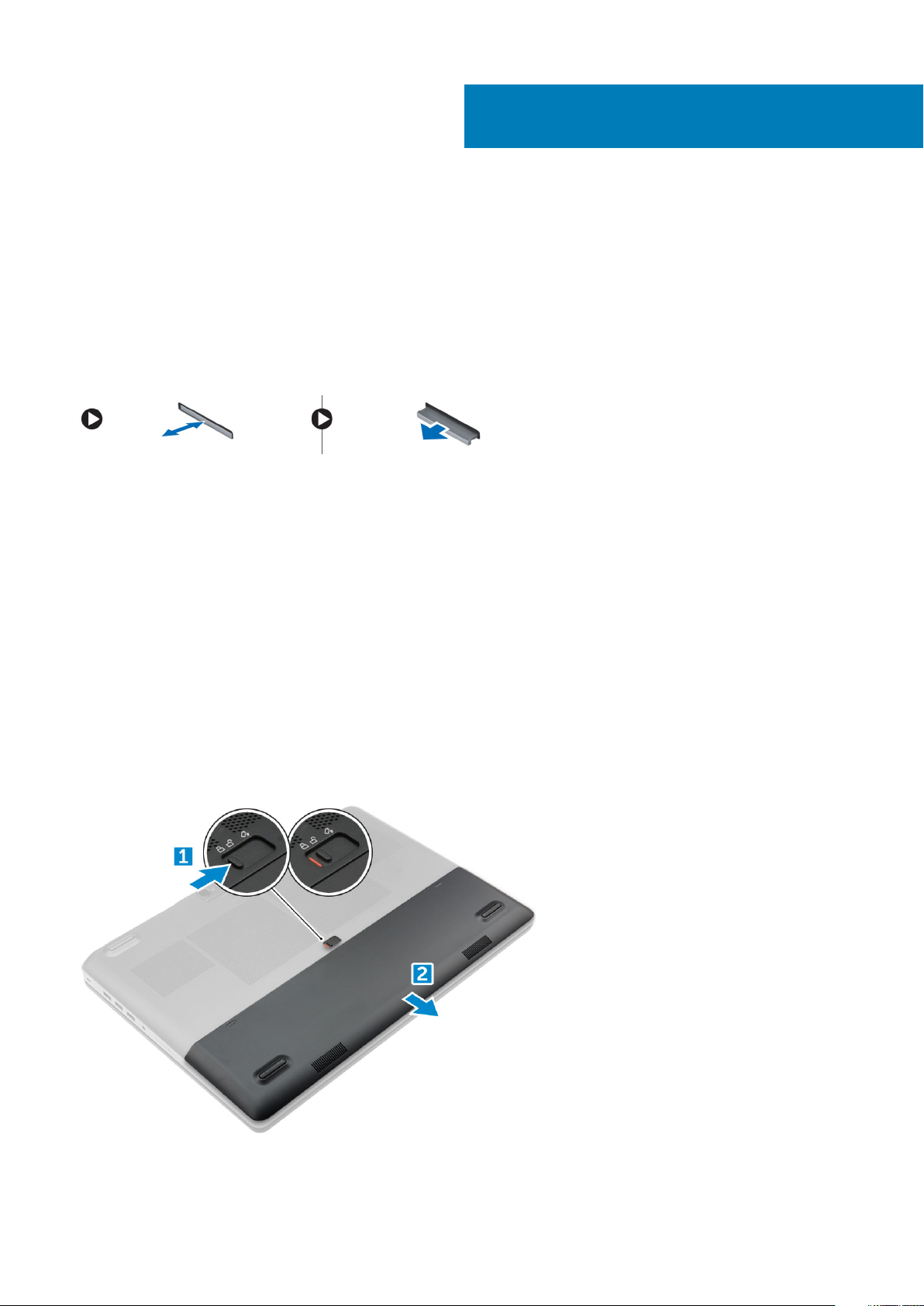
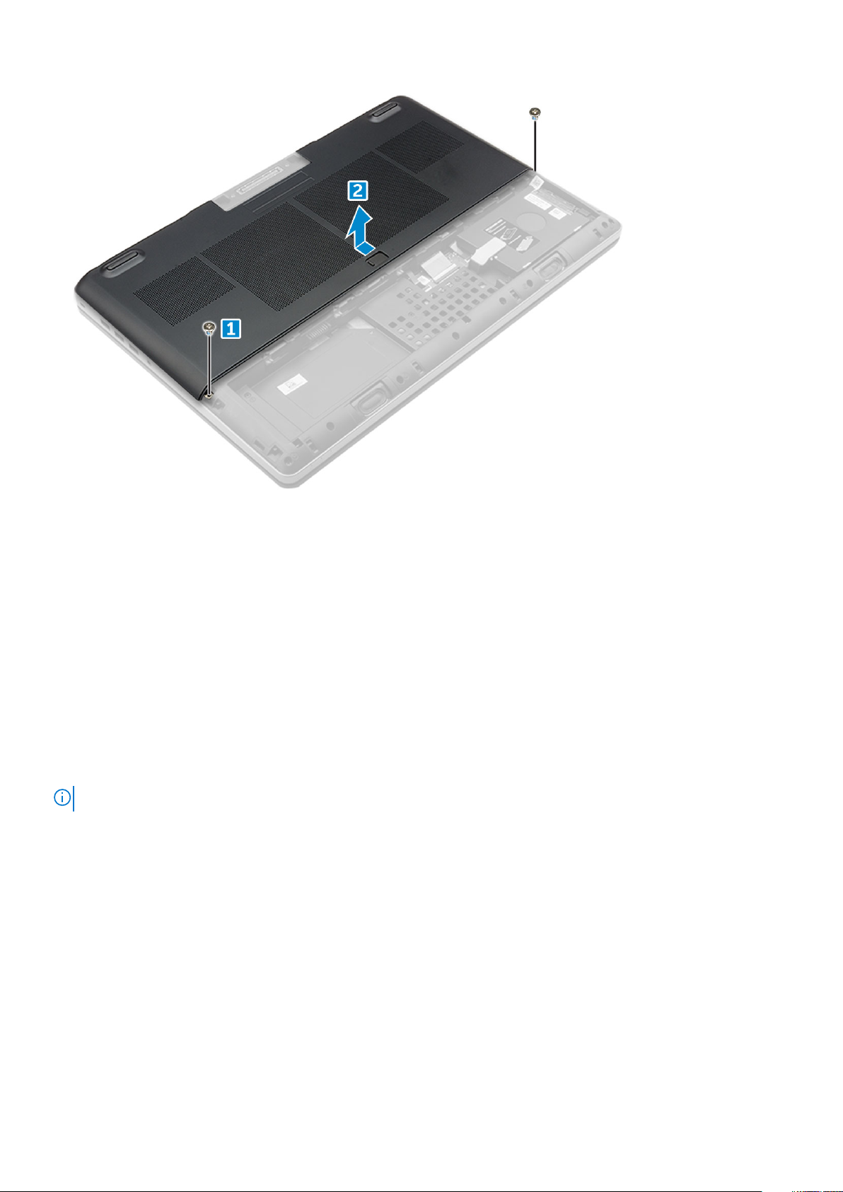
Removing the battery cover
1. Follow the procedure in Before working inside your computer.
2. To remove the battery cover:
a) Slide the release latch towards the unlock icon to release the battery cover [1].
b) Slide and lift the battery cover to remove it from the computer [2].
Disassembly and reassembly 11

Installing the battery cover
1. Slide the battery cover into its slot until it clicks into place.
2. Follow the procedure in After working inside your computer.
Battery
Lithium-ion battery precautions
CAUTION:
• Exercise caution when handling Lithium-ion batteries.
• Discharge the battery as much as possible before removing it from the system. This can be done by disconnecting
the AC adapter from the system to allow the battery to drain.
• Do not crush, drop, mutilate, or penetrate the battery with foreign objects.
• Do not expose the battery to high temperatures, or disassemble battery packs and cells.
• Do not apply pressure to the surface of the battery.
• Do not bend the battery.
• Do not use tools of any kind to pry on or against the battery.
• Ensure any screws during the servicing of this product are not lost or misplaced, to prevent accidental puncture or
damage to the battery and other system components.
• If a battery gets stuck in a device as a result of swelling, do not try to free it as puncturing, bending, or crushing a
Lithium-ion battery can be dangerous. In such an instance, contact for assistance and further instructions.
• If the battery gets stuck inside your computer as a result of swelling, do not try to release it as puncturing, bending,
or crushing a lithium-ion battery can be dangerous. In such an instance, contact Dell technical support for
assistance. See www.dell.com/contactdell.
• Always purchase genuine batteries from www.dell.com or authorized Dell partners and resellers.
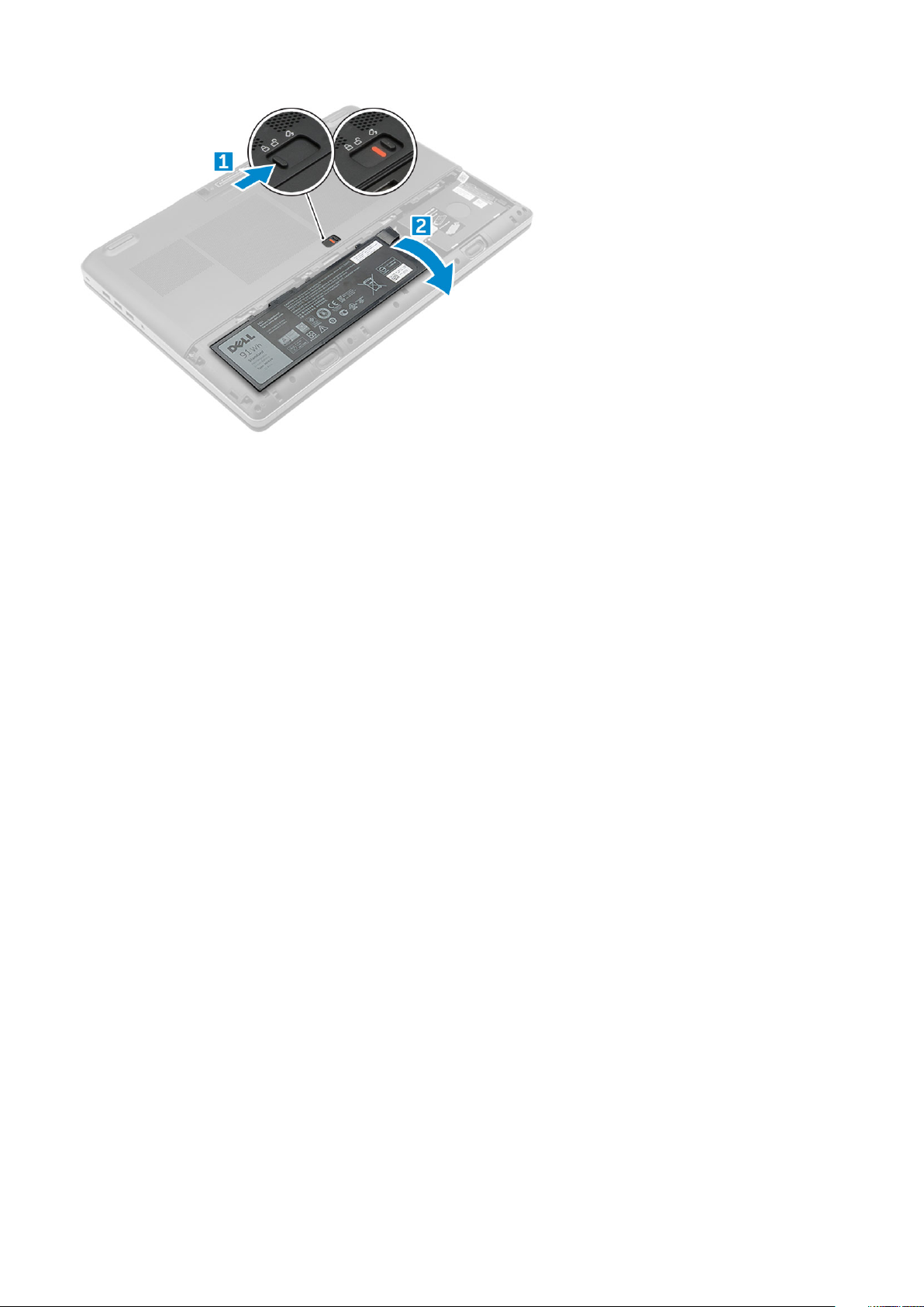
Removing the battery
1. Follow the procedure in Before working inside your computer.
2. Remove the battery cover.
3. To remove battery:
a) Slide the release latch towards from the unlock icon to unlock the battery[1].
b) Lift and remove the battery from the computer [2].
12
Disassembly and reassembly
Installing the battery
1. Slide the battery into its slot until it clicks into place.
2. Install the battery cover.
3. Follow the procedure in After working inside your computer
Hard drive
Removing the hard drive
1. Follow the procedure in Before working inside your computer.
2. Remove the:
a) battery cover
b) battery
3. To remove hard drive:
a) Remove the M3.0x3.0 screws that secure the hard drive to the computer [1].
b) Lift the hard drive latch to release the hard drive [2].
c) Slide and lift the hard drive from the computer [3].
Disassembly and reassembly
13
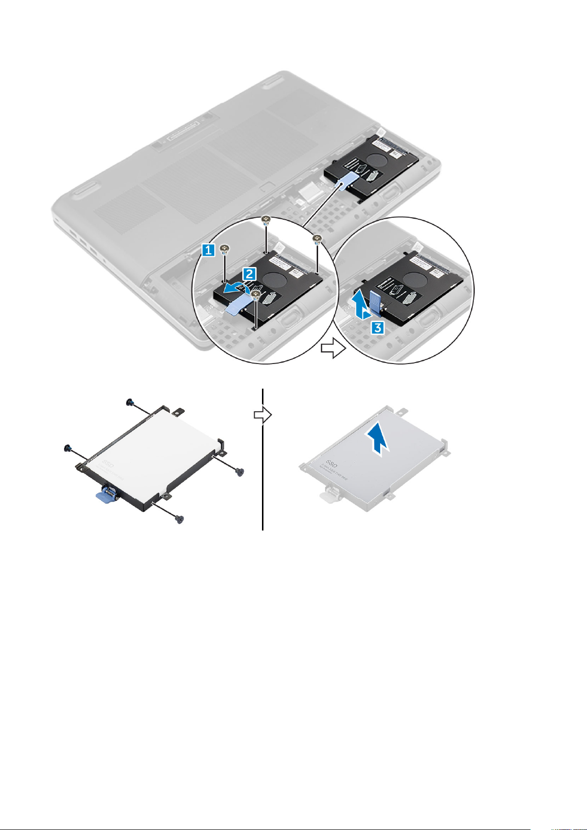
4. Remove the M3.0x3.0 screws that secure the hard drive. Lift the hard drive from the bracket.
Installing the hard drive
1. Replace the M3.0x3.0 screws to secure the hard drive to the hard drive bracket.
2. Insert the hard drive into its slot in the computer.
3. Replace the M3.0x3.0 screws to secure the hard drive to the computer.
4. Install the:
a) battery
b) battery cover
5. Follow the procedure in After working inside your computer.
14
Disassembly and reassembly
Hard drive cable connector
Removing the hard drive cable connector
1. Follow the procedures in Before working inside your computer.
2. Remove the:
a) battery cover
b) battery
c) base cover
d) hard drive
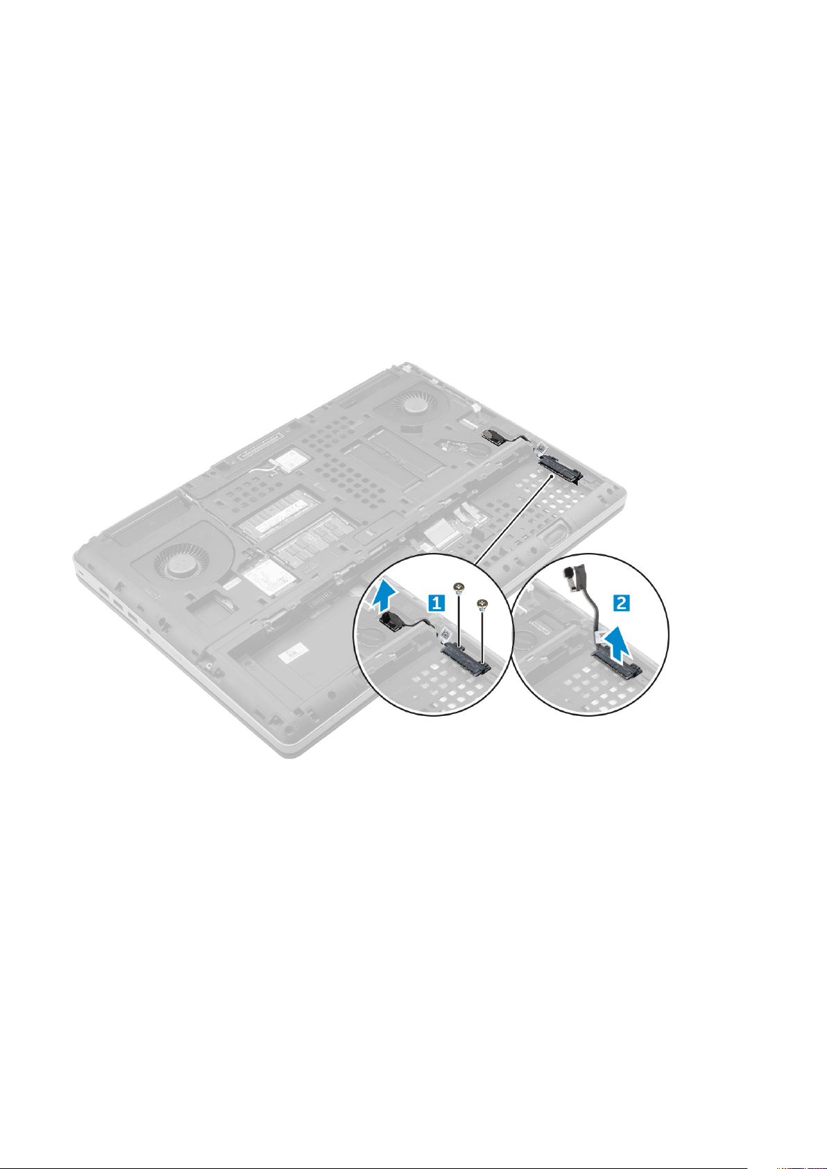
3. To remove the hard drive cable connector:
a) Remove the M2.5x5.0 screws that secure the hard drive connector to the system board [1].
b) Remove the hard drive cable connector from the computer [2].
Installing the hard drive cable connector
1. Connect the hard drive cable to the system board.
2. Insert and route the cable through the routing channel.
3. Replace the M2.5x5.0 screws to secure the hard drive cable connector to the computer.
4. Install the:
a) hard drive
b) base cover
c) battery
d) battery cover
5. Follow the procedure in After working inside your computer.
Disassembly and reassembly
15
Keyboard lattice and Keyboard
Removing the keyboard
1. Follow the procedures in Before working inside your computer.
2. Remove the:
a) battery cover
b) battery
c) hard drive
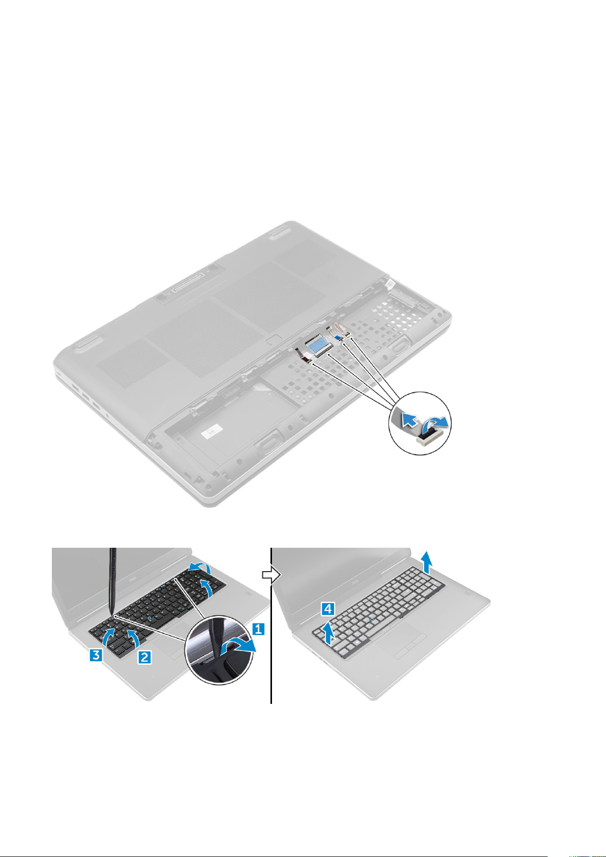
3. To remove keyboard cable:
a) Disconnect the keyboard cables from the touchpad board [1, 2]
4. Using plastic scribe pry the keyboard trim from the bottom and work along the top edge and remove it from the computer [1, 2, 3, 4].
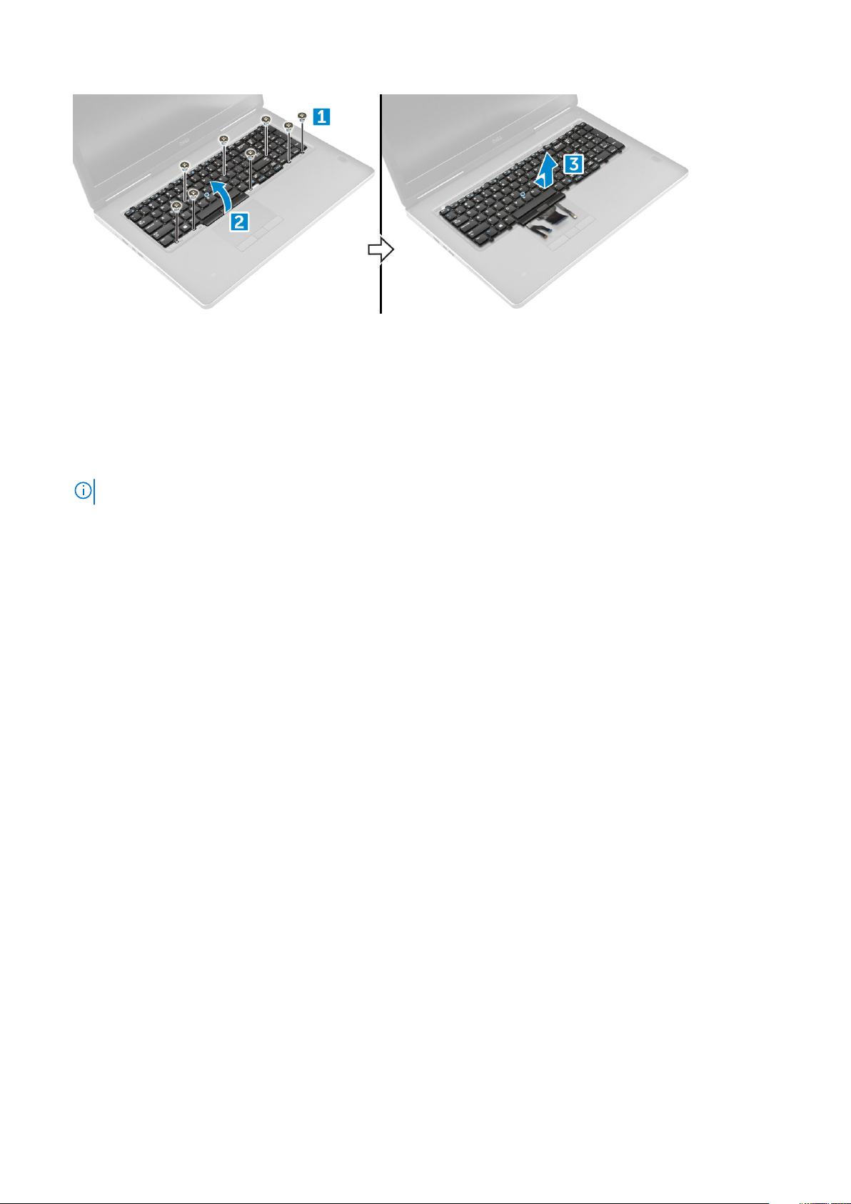
5. To remove the keyboard:
a) Remove the M2.0x2.5 screws that secure the keyboard to the computer [1].
b) Lift and slide the keyboard to remove it away from the computer [2, 3].
16
Disassembly and reassembly
Installing the keyboard
1. Align the keyboard and route the cables back through to the bottom of the compartment.
2. Press and align the keyboard to its compartment.
3. Replace the screws to secure the keyboard to the computer.
4. Slide the keyboard trim and align it to its position on the computer. Ensure that the keyboard trim clicks into its place
5. Connect the keyboard data cables to the touchpad board.
NOTE: Ensure that you fold the keyboard data cable in perfect alignment.
6. Install the:
a) hard drive
b) battery
c) battery cover
7. Follow the procedure in After working inside your computer.
Memory modules
Removing the primary memory module
1. Follow the procedure in Before working inside your computer.
2. Remove the:
a) battery cover
b) battery
c) base cover
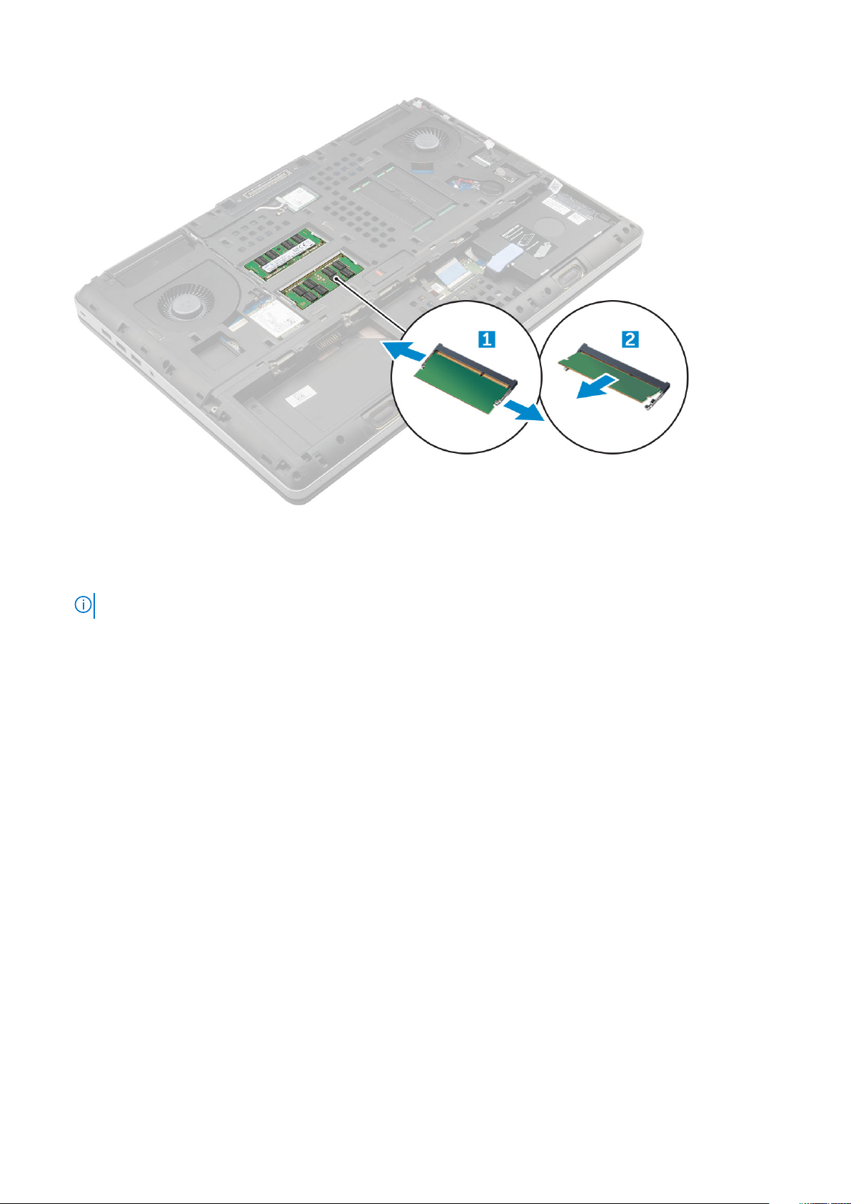
3. To remove primary memory module:
a) Pry the retention clips away from the memory module until it pops up.
b) Lift the memory module and remove it from the computer.
Disassembly and reassembly
17
Installing the primary memory module
1. Insert the memory module into the memory socket.
NOTE: Installing one or three memory modules leads to system performance issues.
2. Press the clips to secure the memory module to the system board.
3. Install the:
a) base cover
b) battery
c) battery cover
4. Follow the procedure in After working inside your computer.
Removing the secondary memory module
1. Follow the procedure in Before working inside your computer.
2. Remove the:
a) battery cover
b) battery
c) hard drive
d) keyboard
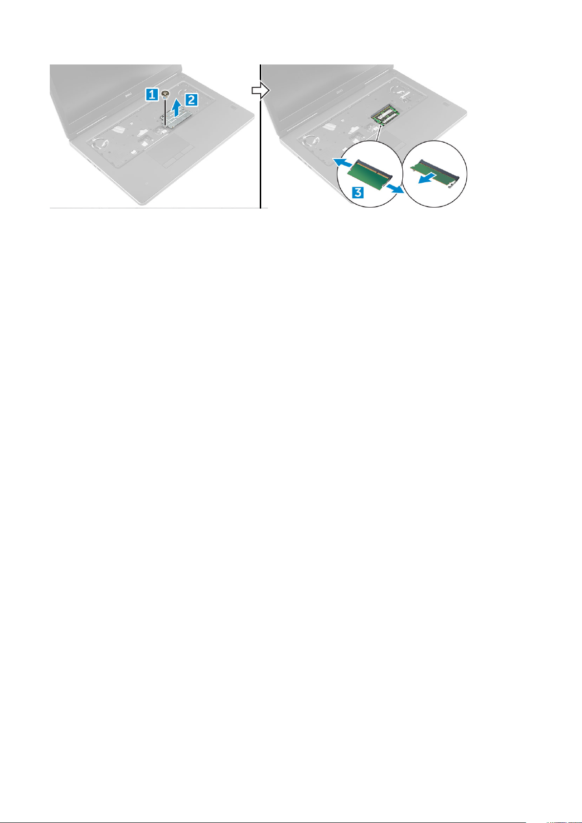
3. To remove the secondary memory module:
a) Remove the screw that secures the memory shield [1].
b) Lift and remove the memory shield from the computer [2].
c) Pry the retention clips away from the memory module until it pops up [3].
d) Lift the memory module and remove it from the computer [4].
18
Disassembly and reassembly
Installing the secondary memory module
1. Insert the memory module into the memory socket.
2. Press the clips to secure the memory module to the system board.
3. Place the memory shield in its original position on the memory module and tighten the screw to secure it to the computer.
4. Install the:
a) keyboard
b) hard drive
c) battery
d) battery cover
5. Follow the procedure in After working inside your computer.
Base cover
Removing the base cover
1. Follow the procedure in Before working inside your computer.
2. Remove the:
a) battery cover
b) battery
3. To remove base cover:
a) Remove the M2.5X5.0 screws that secure the base cover to the computer [1].
b) Slide and lift the base cover away from the computer [2].
Disassembly and reassembly
19
Installing the base cover
1. Slide the base cover to align with the screw holes on the computer.
2. Replace the M2.5X5.0 screws to secure the base cover to the computer.
3. Install the:
a) battery
b) battery cover
4. Follow the procedure in After working inside your computer.
WWAN card
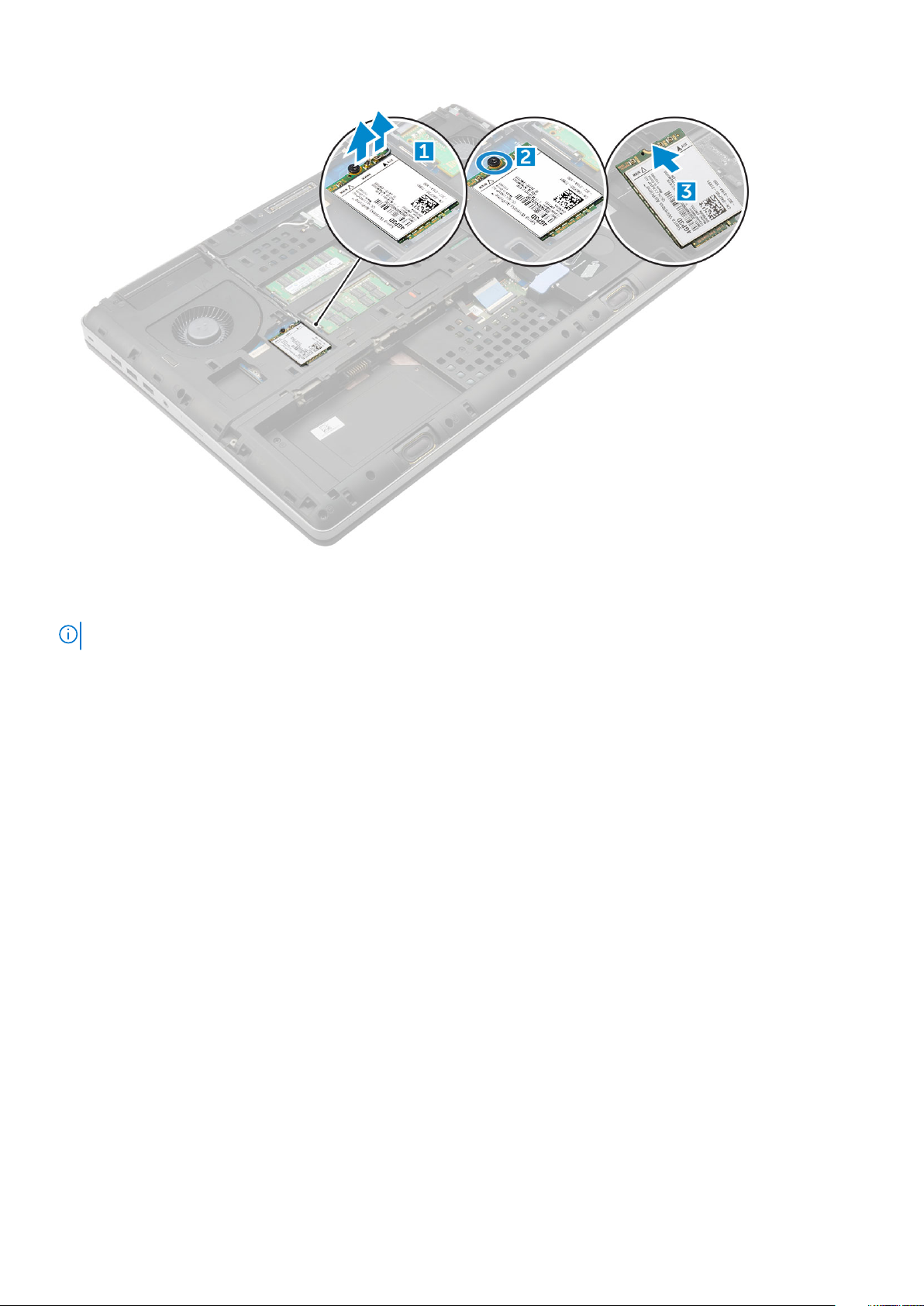
Removing Wireless Wide Area Network - WWAN card
NOTE: Depending on the configuration you choose, you may or may not have WWAN card.
1. Follow the procedure in Before working inside your computer.
2. Remove the:
a) battery cover
b) battery
c) base cover
3. To remove the WWAN card:
a) Disconnect and unroute the antenna cables connected to the WWAN card [1].
b) Remove the M2.0x3.0 screw that secures the WWAN card to the computer [2].
c) Remove the WWAN card from the computer [3].
20
Disassembly and reassembly
Installing the WWAN card
NOTE: Depending on the configuration you choose, you may or may not have WWAN card.
1. Slide the WWAN card to the WWAN card slot.
2. Replace the M2.0x3.0 screw to secure the WWAN card to the computer.
3. Route the antenna cables through the routing channels and connect them to the WWAN card.
4. Install the:
a) base cover
b) battery
c) battery cover
5. Follow the procedure in After working inside your computer.
WLAN card
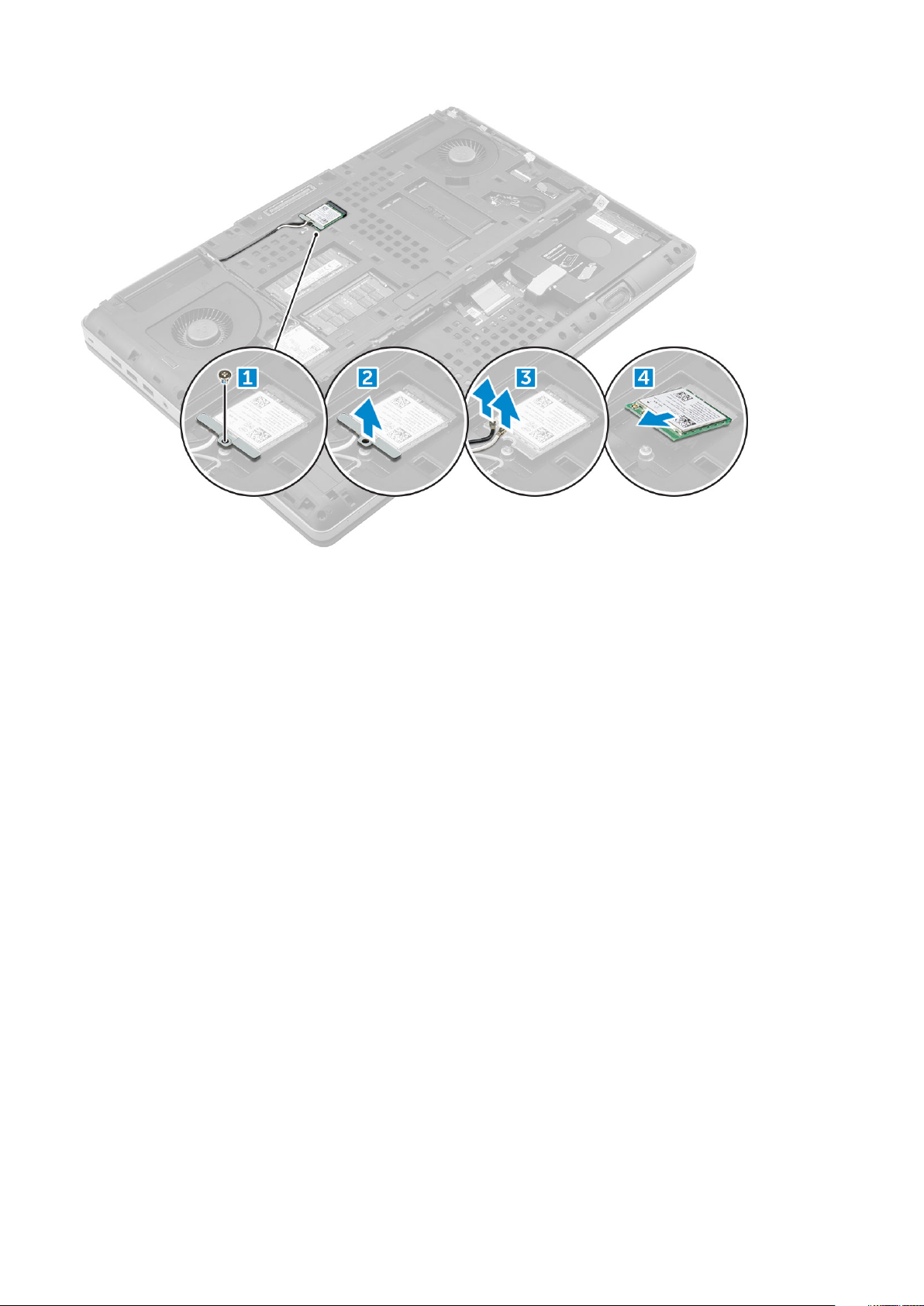
Removing the Wireless Local Area Network - WLAN card
1. Follow the procedure in Before working inside your computer.
2. Remove the:
a) battery cover
b) battery
c) base cover
3. To remove the WLAN card from the computer:
a) Remove the M2.0x3.0 screw that secures the WLAN card to the computer [1].
b) Remove the shield that secures the antenna cables [2].
c) Disconnect and un-route the antenna cables connected to the WLAN card and remove the WLAN card from the computer [3,4].
Disassembly and reassembly
21
Installing the WLAN Card
1. Insert the WLAN card in its slot on the computer.
2. Route the antenna cables through the routing channel and connect them to the WLAN card.
3. Align the shield and tighten the M2.0x3.0 screw to secure the WLAN card to the computer.
4. Install the:
a) base cover
b) battery
c) battery cover
5. Follow the procedures in After working inside your computer.
Solid State Drive
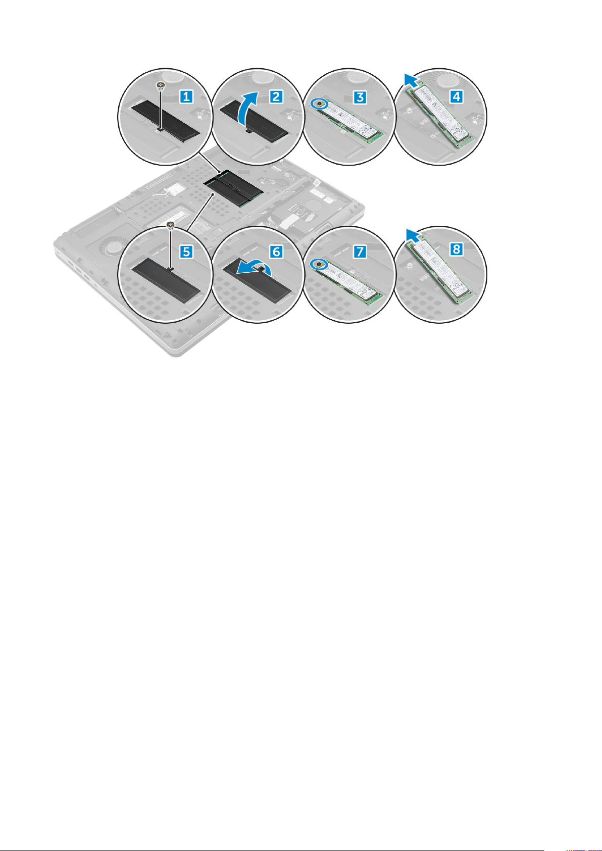
Removing the M.2 Solid State Drive -SSD module
1. Follow the procedures in Before working inside your computer.
2. Remove the:
a) battery cover
b) battery
c) base cover
3. To remove the SSD module:
a) Remove the M2.0x3.0 screw that secures the thermal plate to the computer.
b) Remove the thermal plate from the computer.
c) Remove the M2.0x3.0 screw that secures the SSD to the computer.
d) Remove the SSD away from the computer.
22
Disassembly and reassembly
Installing the M.2 SSD module
1. Place the SSD in its slot.
2. Replace the M2.0x3.0 screw to secure the SSD to the computer.
3. Place the thermal plate on the SSD.
4. Replace the M2.0x3.0 screw to secure the thermal plate to the computer.
5. Install the:
a) base cover
b) battery
c) battery cover
6. Follow the procedure in After working inside your computer.
Coin-cell battery
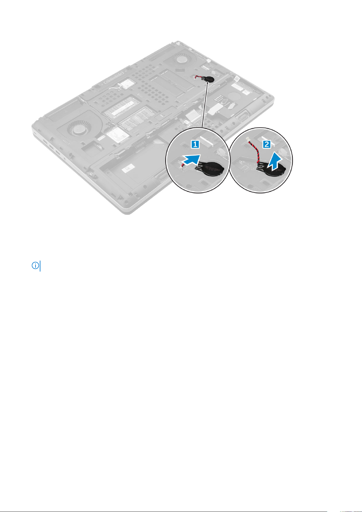
Removing the coin cell battery
1. Follow the procedures in Before working inside your computer.
2. Remove the:
a) battery cover
b) battery
c) base cover
3. To remove coin cell battery:
a) Disconnect the coin cell battery cable from the computer [1].
b) Pry and lift the coin cell battery from the computer [2].
Disassembly and reassembly
23
Installing the coin cell battery
1. Replace the coin cell battery in its slot on the computer.
2. Connect the coin cell battery cable to the comupter.
NOTE: Ensure that the coin cell battery cable does not protrude outside its compartment.
3. Install the:
a) base cover
b) battery
c) battery cover
4. Follow the procedure in After working inside your computer.
Power connector port
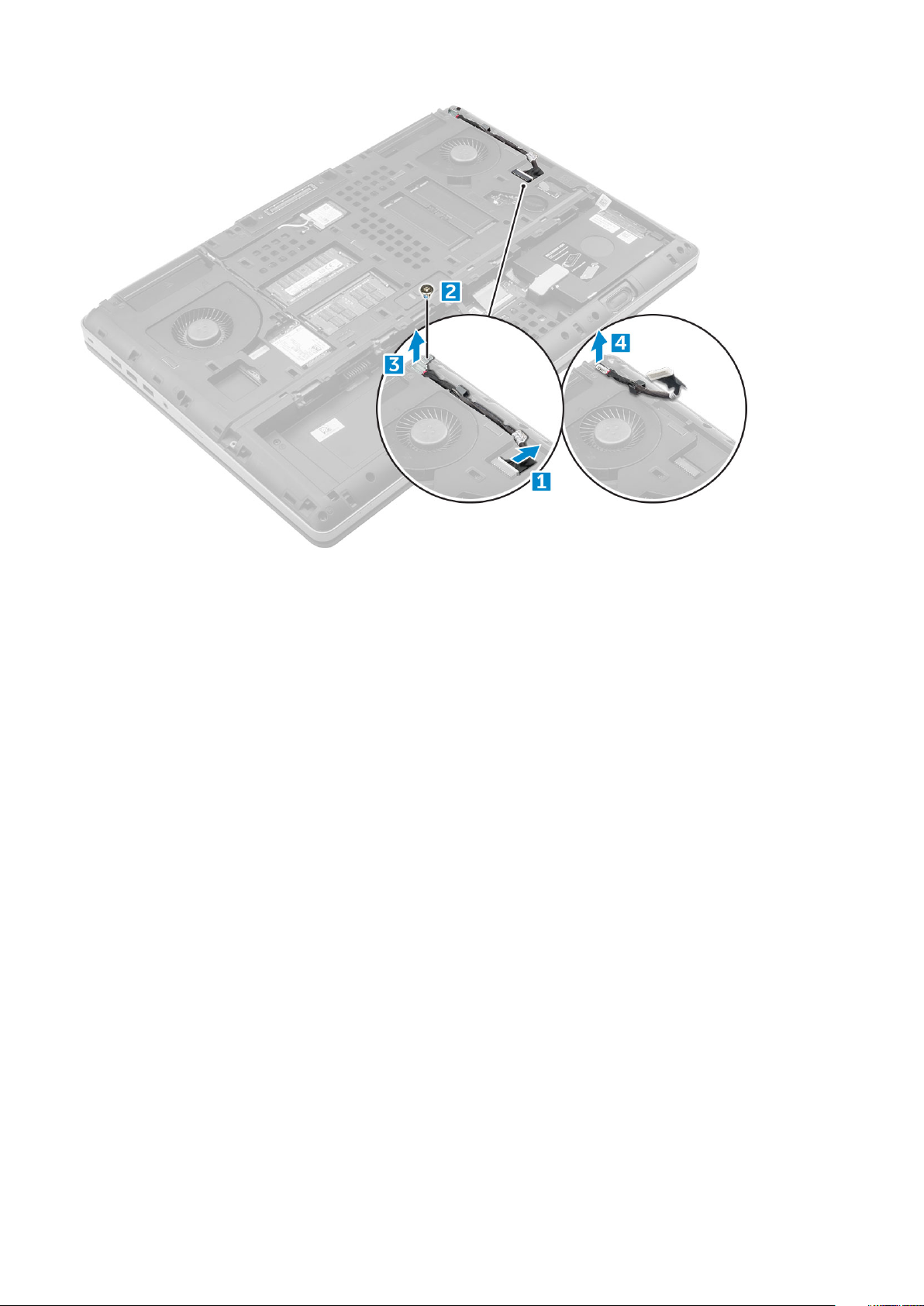
Removing the power connector port
1. Follow the procedure in Before working inside your computer.
2. Remove the:
a) battery cover
b) battery
c) base cover
3. To remove power connector port:
a) Disconnect the power connector cable from the computer [1].
b) Remove the M2.5x5.0 screw to remove the bracket from the computer [2].
c) Remove the bracket from the computer [3].
d) Lift the power connector port from the computer [4].
24
Disassembly and reassembly
Installing the power connector port
1. Replace the power connector cable on the computer.
2. Route the cable through the routing channel
3. Replace the bracket.
4. Replace the M2.5x5.0 screw to secure the power connector port to the computer.
5. Connect the power connector cable.
6. Install the:
a) base cover
b) battery
c) battery cover
7. Follow the procedure in After working inside your computer.
Palm rest
Removing the palmrest
1. Follow the procedure in Before working inside your computer.
2. Remove the:
a) battery cover
b) battery
c) base cover
d) hard drive
e) keyboard
3. Remove the 15 screws (M2.5x5.0, M2.0x3.0)at the bottom of the computer which secure the palmrest to the computer .
Disassembly and reassembly
25
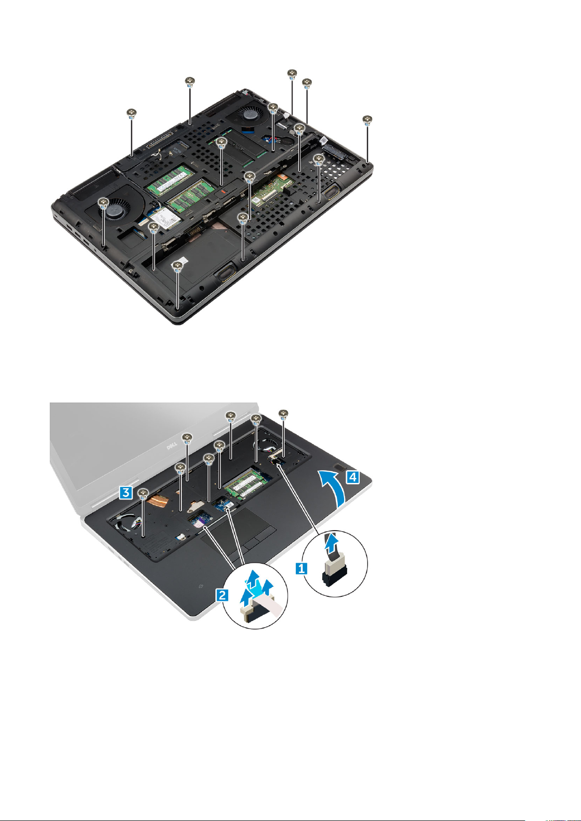
4. To remove palmrest:
a) Lift the tab and disconnect the fan cable [1] and system board cable [ 2].
b) Remove the 11 screws (M2.5x5.0)that secure the palmrest to the computer [3].
c) By using plastic scribe release the tabs on the edges of the palmrest and remove the palmrest from the computer [4].
Installing the palmrest
1. Align the palmrest on the computer and press until it snaps in its place.
2. Replace the 11 screws (M2.5x5.0) that secure the palmrest to the computer.
3. Connect the following cables:
a) system board cable
b) fan cable
26
Disassembly and reassembly

4. Flip the computer and tighten the 15 screws (M2.5x5.0, M2.0x3.0) at the bottom of the computer.
5. Install the:
a) keyboard
b) hard drive
c) base cover
d) battery
e) battery cover
6. Follow the procedure in After working inside your computer.
Fingerprint reader
Removing the fingerprint reader
1. Follow the procedure in Before working inside your computer.
2. Remove the:
a) SD card
b) battery cover
c) battery
d) base cover
e) hard drive
f) keyboard
g) hard drive cable
h) secondary memory
i) primary memory
j) WLAN card
k) WWAN card
l) M.2 SSD card
m) graphic card
n) power connector port
o) palmrest
3. To remove fingerprint reader:
a) Peel the adhesive tape that secures fingerprint reader [1].
b) Remove and lift the M2.0X3 screws that secure metal bracket on the chassis [2].
c) Disconnect the cable and lift the fingerprint reader from the chassis [3].
Disassembly and reassembly
27

Installing the fingerprint reader
1. Align the fingerprint reader into its original position on the chassis.
2. Connect the finger print reader cable.
3. Place the metal bracket on the chassis.
4. Replace the M2.0X3 screws to secure the fingerprint reader to the chassis.
5. Affix the adhesive tape to secure the fingerprint reader.
6. Install the:
a) palmrest
b) power connector port
c) graphic card
d) M.2 SSD card
e) WWAN card
f) WLAN card
g) primary memory
h) secondary memory
i) HDD cable
j) keyboard
k) hard drive
l) base cover
m) battery
n) battery cover
o) SD card
7. Follow the procedure in After working inside your computer.
Power switch board
Removing the power switch board
28
Disassembly and reassembly

1. Follow the procedure in Before working inside your computer.
2. Remove the:
a) battery cover
b) battery
c) base cover
d) hard drive
e) keyboard
f) palmrest
3. To remove power switch board:
a) Disconnect the power switch board cable from the computer [1].
b) Remove the M2.0X3 screws that secure power switch board to the computer [2].
c) Remove the power switch board from the computer [3].
Installing the power switch board
1. Place the power switch in the slot on the computer.
2. Replace the M2.0X3 screws that secure power switch board on the computer.
3. Connect the power switch board cable on the computer.
4. Install the:
a) palmrest
b) keyboard
c) hard drive
d) base cover
e) battery
f) battery cover
5. Follow the procedure in After working inside your computer.
Disassembly and reassembly
29

ExpressCard Reader
Removing the expresscard
1. Follow the procedure in Before working inside your computer.
2. Remove the:
a) battery cover
b) battery
c) base cover
d) hard drive
e) keyboard
f) palmrest
3. To remove expresscard:
a) Disconnect the expresscard cable from the computer [1].
b) Remove the M2.5x5.0 screws that secure expresscard to the computer [2].
c) Remove the expresscard board from the computer [3].
Installing the expresscard
1. Place the expresscard on the computer.
2. Replace the M2.5x5.0 screws that secure expresscard on the computer.
3. Connect the expresscard cable.
4. Install the:
a) palmrest
b) keyboard
c) hard drive
d) base cover
e) battery
f) battery cover
30
Disassembly and reassembly

5. Follow the procedure in After working inside your computer.
USB board
Removing the USB board
1. Follow the procedure in Before working inside your computer.
2. Remove the:
a) battery cover
b) battery
c) base cover
d) hard drive
e) keyboard
f) palmrest
3. To remove USB board:
a) Disconnect the USB board cable from the computer [1].
b) Remove the adhesive tape that secures USB board to the computer [2].
c) Lift the USB board from the computer [3].
Installing the USB board
1. Place the USB board on the computer.
2. Affix the adhesive tape to secure the USB board on the computer
3. Connect the USB board cable.
4. Install the:
a) palmrest
b) keyboard
c) hard drive
Disassembly and reassembly
31

d) base cover
e) battery
f) battery cover
5. Follow the procedure in After working inside your computer.
Input-Output board
Removing the left Input-Output -IO board
1. Follow the procedure in Before working inside your computer.
2. Remove the:
a) battery cover
b) battery
c) base cover
d) hard drive
e) keyboard
f) palmrest
3. To remove I/O board:
a) Remove the M2.5x5.0 screws that secure the thunderbolt bracket to the computer [1].
b) Lift the bracket from the thunderbolt connector [2].
c) Remove the M2.5x5.0 screws that secure the I/O board to the computer [3].
d) Lift the I/O board upwards to and remove it from the computer.
Installing the left IO board
1. Slide the I/O board into its slot on the computer.
2. Install the thunderbolt bracket.
3. Replace the M2.5x5.0 screws to secure the I/O board to the computer.
4. Install the:
a) palmrest
32
Disassembly and reassembly

b) keyboard
c) hard drive
d) base cover
e) battery
f) battery cover
5. Follow the procedures in After working inside your computer.
Removing the right Input-Output - IO board
1. Follow the procedure in Before working inside your computer.
2. Remove the:
a) SD card
b) battery cover
c) battery
d) base cover
e) hard drive
f) keyboard
g) palmrest
3. To remove I/O board:
a) Disconnect the right speaker cable from the I/O board [1].
b) Remove the M2.5x5.0 screws that secure the I/O board to the computer [2].
c) Lift the I/O board upwards to and remove it from the computer [3].
Installing the right IO board
1. Connect the I/O board connector cable and slide the I/O board into its slot on the computer.
2. Replace the M2.5x5.0 screws to secure the I/O board to the computer.
3. Connect the speaker cable to the I/O board.
4. Install the:
a) palmrest
b) keyboard
Disassembly and reassembly
33

c) hard drive
d) base cover
e) battery
f) battery cover
g) SD card
5. Follow the procedure in After working inside your computer.
Heat sink
Removing the heat sink assembly
1. Follow the procedure in Before working inside your computer.
2. Remove the:
a) battery cover
b) battery
c) base cover
d) hard drive
e) keyboard
f) palmrest
3. To remove heat sink:
a) Disconnect the fan cables from the computer [1, 2] .
b) Loosen the captive M2.5x5.0 screws that secure the heat sink assembly to the computer [3].
NOTE:
Remove the screws that secure the heat sink to the system board in the order stamped onto the heat sink
next to the screws [1, 2, 3, 4, 5, 6, 7, 8].
c) Lift and remove the heat sink assembly from the computer [4].
Installing the heat sink assembly
1. Insert the heat-sink assembly in its slot.
2. Tighten the captive M2.5x5.0 screws to secure the heat-sink assembly to the computer.
Tighten the screws on the system board in the order stamped onto the heat sink next to the screws [1, 2, 3, 4,
NOTE:
5, 6, 7, 8].
3. Connect the fan cables to the system board.
4. Install the:
a) palmrest
b) keyboard
c) hard drive
d) base cover
34
Disassembly and reassembly

e) battery
f) battery cover
5. Follow the procedure in After working inside your computer.
Graphics card
Removing the graphic card
1. Follow the procedure in Before working inside your computer.
2. Remove the:
a) battery cover
b) battery
c) base cover
d) hard drive
e) keyboard
f) palmrest
g) heat sink
3. To remove the graphic card:
a) Remove the M2.0x3.0 screws that secure the graphic card to the computer [1].
b) Remove the graphic card from the computer [2].
Installing the graphic card
1. Slide the graphic card into its original position in the computer.
2. Replace the M2.0x3.0 screws to secure the graphic card to the computer.
3. Install the:
a) heat sink
b) palmrest
c) keyboard
d) hard drive
Disassembly and reassembly
35

e) base cover
f) battery
g) battery cover
4. Follow the procedure in After working inside your computer.
System board
Removing the system board
1. Follow the procedure in Before working inside your computer.
2. Remove the:
a) SD card
b) battery cover
c) battery
d) base cover
e) hard drive
f) keyboard
g) hard drive cable
h) secondary memory
i) primary memory
j) WLAN card
k) WWAN card
l) M.2 SSD card
m) graphic card
n) power connector port
o) palmrest
p) I/O board (left)
q) I/O board (right)
r) heat sink
3. To disconnect and remove the eDP cable:
a) Remove the M2.5x5.0 screws that secure the shield to the system board [1].
b) Lift the metal shield away from the eDP cable [2].
c) Disconnect the eDP cable [3].
d) Lift the tab and disconnect the power connector cable [4].
36
Disassembly and reassembly

4. To remove system board:
a) Remove the M2.5X5.0 screws that secure the system board [1].
b) Slide and lift system board from the computer [2].
Installing the system board
1. Align the system board into its original position on the computer.
2. Replace the M2.5x5.0 screws to secure the system board to the computer.
3. Connect the following cables:
a) power connector
b) eDP
4. Place the metal bracket and tighten the M2.5x5.0 screw to secure the eDP cable to the computer.
5. Install the:
Disassembly and reassembly
37

a) heat sink
b) I/O board (right)
c) I/O board (left)
d) palmrest
e) power connector port
f) graphic card
g) M.2 SSD card
h) WWAN card
i) WLAN card
j) primary memory
k) secondary memory
l) HDD cable
m) keyboard
n) hard drive
o) base cover
p) battery
q) battery cover
r) SD card
6. Follow the procedure in After working inside your computer.
LED board
Removing the LED board
1. Follow the procedures in Before working inside your computer.
2. Remove the:
a) battery cover
b) battery
c) base cover
d) hard drive
e) keyboard
f) secondary memory
g) palmrest
3. To remove LED board:
a) Lift the tab and disconnect the LED-board cable from the LED board [1].
b) Remove the M2.0x3.0 screw that secures the LED board to the computer and remove it from the computer [2].
38
Disassembly and reassembly

Installing the LED board
1. Align the LED board to its original position on the computer.
2. Replace the M2.0x3.0 screw to secure the LED board to the computer.
3. Connect the LED-board cable to the LED board and secure it through the routing channel.
4. Install the:
a) palmrest
b) secondary memory
c) keyboard
d) hard drive
e) base cover
f) battery
g) battery cover
5. Follow the procedure in After working inside your computer.
Speaker
Removing the speakers
1. Follow the procedure in Before working inside your computer.
2. Remove the:
a) battery cover
b) battery
c) base cover
d) hard drive
e) keyboard
f) palmrest
3. To remove the speaker:
a) Disconnect the speaker cable from the system board [1].
Disassembly and reassembly
39

b) Unroute the speaker cable and remove the cable from the routing tabs.
c) Lift the speakers, along with the speaker cable and remove it away from the computer [2].
Installing the speakers
1. Align the speakers along the slots on the computer.
2. Route the speaker cable through the routing tabs on the computer.
3. Connect the speaker cable to the system board.
4. Install the:
a) palmrest
b) keyboard
c) hard drive
d) base cover
e) battery
f) battery cover
5. Follow the procedure in After working inside your computer.
Display assembly
Removing the display assembly
1. Follow the procedure in Before working inside your computer.
2. Remove the:
a) battery cover
b) battery
c) base cover
d) hard drive
e) keyboard
f) WLAN card
g) WWAN card
40
Disassembly and reassembly

h) palmrest
3. To remove hinge cap:
a) Remove the M2.5x4.0 screws that secure the hinge caps [1].
b) Remove the hinge caps from the computer [2].
4. To disconnect antenna cables:
a) Flip the computer and remove the M2.0X3 screws from the computer [1].
b) Pull the antenna cables through the routing hole [2].
5. To remove display assembly:
a) Flip the computer and open the display.
b) Remove the M2.0X3 screw that secures the eDP cable bracket [1].
c) Remove the eDP cable bracket [2].
d) Peel off the tape on the heat sink and disconnect the eDP cable from the system board [3].
e) Remove the M2.0X3 screws that secure the display assembly to the computer and remove it from the computer [4].
Disassembly and reassembly
41

Installing the display assembly
1. Insert the display assembly into the slots on the computer.
2. Replace the M2.0X3 screws to secure the display assembly in place.
3. Affix the tape on the heat sink.
4. Connect the eDP cable to the connectors on the system board.
5. Insert the wireless antenna cables through the routing hole on the chassis.
6. Replace the display assembly M2.0X3 screws at the bottom and back of the computer.
7. Align the display hinge cap and tighten the M2.5x4.0 screws to secure it to the computer.
8. Connect the antenna cables to the connectors.
9. Install the:
a) palmrest
b) WWAN card
c) WLAN card
d) keyboard
e) hard drive
f) base cover
g) battery
h) battery cover
10. Follow the procedure in After working inside your computer.
Display bezel
Removing the display bezel
1. Follow the procedure in Before working inside your computer.
2. Remove the:
a) battery cover
b) battery
c) base cover
d) hard drive
e) keyboard
f) palmrest
42
Disassembly and reassembly

g) display assembly
3. To remove display bezel:
a) Pry up all the edges of the display bezel [1, 2, 3] using a plastic scribe.
Installing the display bezel
1. Place the display bezel on the display assembly.
2. Press the edges of the display bezel until it clicks onto the display assembly.
3. Install the:
a) display assembly
b) palmrest
c) keyboard
d) hard drive
e) base cover
f) battery
g) battery cover
4. Follow the procedure in After working inside your computer.
Display panel
Removing the display panel
1. Follow the procedure in Before working inside your computer.
2. Remove the:
a) battery cover
b) battery
c) base cover
d) hard drive
e) keyboard
Disassembly and reassembly
43

f) palmrest
g) display assembly
h) display bezel
3. To remove screws from the display panel :
a) Remove the M2.0X3 screws that secure the display panel to the display assembly [1].
b) Lift the display panel and turn the display panel over to access the eDP cable [2].
4. To remove display panel:
a) Peel the adhesive tape to access the eDP cable [1].
b) Remove the blue adhesive tape [2].
c) Lift the metal tab display panel [3].
d) Disconnect the cable and lift the display panel.
44
Disassembly and reassembly

Installing the display panel
1. To install the display panel:
a) Connect the eDP cable to the connector on the back of the display panel and affix the adhesive tape.
b) Align the display panel with the tabs on the display assembly.
c) Replace the M2.0X3 screws to secure the display panel to the display assembly.
2. Install the:
a) display bezel
b) display assembly
c) palmrest
d) keyboard
e) hard drive
f) base cover
g) battery
h) battery cover
3. Follow the procedure in After working inside your computer.
Removing the display panel
NOTE: For touch systems perform following step.
1. Follow the procedure in Before working inside your computer.
2. Remove the:
a) battery cover
b) battery
c) base cover
d) hard drive
e) keyboard
f) palmrest
g) display assembly
Disassembly and reassembly
45

h) display bezel
3. To remove the display panel:
a) Using a plastic scribe lift the edges of the display panel to disengage it from the display assembly.
b) Lift the display panel and turn the display panel over to access the eDP and display cables.
c) Peel the adhesive tape to access the eDP cable [1, 5].
d) Disconnect the eDP and display cables from the connector on the back of the display panel [2, 3, 4, 6].
46
Disassembly and reassembly

Installing the display panel
NOTE: For touch systems perform following steps.
1. To install the display panel for touch systems:
a) Place the display panel on a flat surface.
b) Connect the eDP and display cables to the connector on the back of the display panel and affix the adhesive tape.
c) Turn the display assembly over.
d) Align the display panel with the tabs on the display assembly.
e) Press the edges of the display panel to secure it to the display assembly.
2. Install the:
a) display bezel
b) display assembly
c) palmrest
d) keyboard
e) hard drive
f) base cover
g) battery
h) battery cover
3. Follow the procedure in After working inside your computer.
Disassembly and reassembly
47

Display bracket
Removing the display bracket
1. Follow the procedure in Before working inside your computer.
2. Remove the:
a) battery cover
b) battery
c) base cover
d) hard drive
e) keyboard
f) palmrest
g) display assembly
h) display bezel
i) display panel
3. To remove display bracket:
a) Remove the M2.5x4.0 screws that secure display cover [1].
b) Remove the display brackets from the display cover [2].
Installing the display bracket
1. Place the display brackets in its slot on the display cover.
2. Replace the M2.5x4.0 screws to secure the display bracket..
3. Install the:
a) display panel
b) display bezel
c) display assembly
d) palmrest
48
Disassembly and reassembly

e) keyboard
f) hard drive
g) base cover
h) battery
i) battery cover
4. Follow the procedure in After working inside your computer.
Display hinges
Removing the display hinge
1. Follow the procedure in Before working inside your computer.
2. Remove the:
a) battery cover
b) battery
c) base cover
d) hard drive
e) keyboard
f) palmrest
g) display assembly
h) display bezel
i) display panel
3. To remove display hinge:
a) Remove the M2.5x4.0 screws that secure display hinges [1].
b) Remove the display hinges from the display cover [2].
Installing the display hinge
1. Place the display hinge in its slot on the display cover.
Disassembly and reassembly
49

2. Replace the M2.5x4.0 screws to secure the display hinge.
3. Install the:
a) display panel
b) display bezel
c) display assembly
d) palmrest
e) keyboard
f) hard drive
g) base cover
h) battery
i) battery cover
4. Follow the procedure in After working inside your computer.
Display cover
Replacing the display cover
1. Follow the procedure in Before working inside your computer.
2. Remove the:
a) battery cover
b) battery
c) base cover
d) hard drive
e) keyboard
f) palmrest
g) display assembly
h) display bezel
i) display panel
j) display bracket
k) display hinge
l) camera
m) eDP cable
The component you are left with is the display cover.
3. Install:
a) eDP cable
b) camera
c) display hinge
d) display bracket
e) display panel
50
Disassembly and reassembly

f) display bezel
g) display assembly
h) palmrest
i) keyboard
j) hard drive
k) base cover
l) battery
m) battery cover
4. Follow the procedure in After working inside your computer.
eDP cable
Removing the eDP cable
1. Follow the procedure in Before working inside your computer.
2. Remove the:
a) battery cover
b) battery
c) base cover
d) hard drive
e) keyboard
f) palmrest
g) display assembly
h) display bezel
i) display panel
3. To remove eDP cable:
a) Peel the eDP cable [1].
b) Unroute the eDP cable from the display cover [2, 3].
Disassembly and reassembly
51

Installing the eDP cable
1. Route the eDP cable on the display cover.
2. Affix the eDP cable on the display cover.
3. Install the:
a) display panel
b) display bezel
c) display assembly
d) palmrest
e) keyboard
f) hard drive
g) base cover
h) battery
i) battery cover
4. Follow the procedure in After working inside your computer.
Camera
Removing the camera
1. Follow the procedure in Before working inside your computer.
2. Remove the:
a) battery cover
b) battery
c) base cover
d) hard drive
e) keyboard
f) palmrest
g) display assembly
h) display bezel
3. To remove camera:
a) Peel the eDP cable and disconnect the camera cable from the computer [1].
b) Lift the camera module from the computer [2].
52
Disassembly and reassembly

Installing the camera
1. Place the camera module in its slot on the computer.
2. Connect the camera cable.
3. Affix the eDP cable.
4. Install the:
a) display bezel
b) display assembly
c) palmrest
d) keyboard
e) hard drive
f) base cover
g) battery
h) battery cover
5. Follow the procedure in After working inside your computer.
Disassembly and reassembly
53

Technology and components
This chapter details the technology and components available in the system.
Topics:
• Power adapter
• Processors
• USB features
• HDMI 1.4
Power adapter
This laptop is shipped with 240 W power adapters.
WARNING: When you disconnect the power adapter cable from the laptop, grasp the connector, not the cable itself, and
then pull firmly but gently to avoid damaging the cable.
WARNING: The power adapter works with electrical outlets worldwide. However, power connectors and power strips
vary among countries. Using an incompatible cable or improperly connecting the cable to the power strip or electrical
outlet may cause fire or equipment damage.
3
Processors
Latitude 7720 is shipped with any of the following processors:
7th generation processors (KabyLake)
• Intel Core Xeon E3-1535M v6 (Quad Core Xeon 3.10GHz, 4.20GHz Turbo, 8MB 45W)
• Intel Core Xeon E3-1505M v6 (Quad Core Xeon 3.00GHz, 4.00GHz Turbo, 8MB 45W)
• Intel Core i7-7920HQ (Quad Core 3.10GHz, 4.10GHz Turbo, 8MB 45W)
• Intel Core i7-7820HQ (Quad Core 2.90GHz, 3.90GHz Turbo, 8MB 45W)
• Intel Core i7-7700HQ (Quad Core 2.80GHz, 3.80GHz Turbo, 6MB 45W)- non vPro
• Intel Core i5-7440HQ (Quad Core 2.80GHz, 3.80GHz Turbo, 6MB 45W)
• Intel Core i5-7300HQ (Quad Core 2.50GHz, 3.50GHz Turbo, 6MB 45W)
6th generation processors (SkyLake)
• Intel Core Xeon E3-1575M v5 (Quad Core Xeon 3.00GHz, 3.90GHz Turbo, 8MB 45W)
• Intel Core Xeon E3-1545M v5 (Quad Core Xeon 2.90GHz, 3.80GHz Turbo, 8MB 45W)
• Intel Core i7-6920HQ (Quad Core 2.90GHz, 3.80GHz Turbo, 8MB 45W)
• Intel Core i7-6820HQ (Quad Core 2.70GHz, 3.60GHz Turbo, 8MB 45W)
NOTE: The clock speed and performance varies depending on the workload and other variables.
Kaby Lake — 7th Generation Intel Core processors
The 7th Gen Intel Core processor (Kaby Lake) family is the successor of 6th generation processors (Skylake). It's main features include:
• Intel 14nm Manufacturing Process Technology
• Intel Turbo Boost Technology
• Intel Hyper Threading Technology
• Intel Built-in Visuals
• Intel HD graphics - exceptional videos, editing smallest details in the videos
• Intel Quick Sync Video - excellent video conferencing capability, quick video editing and authoring
54 Technology and components

• Intel Clear Video HD - visual quality and color fidelity enhancements for HD playback and immersing web browsing
• Integrated memory controller
• Intel Smart Cache
• Optional Intel vPro technology (on i5/i7) with Active Management Technology 11.6
• Intel Rapid Storage Technology
NOTE: Windows 7 and 8 are not supported by systems with 7th generation processors
USB features
Universal Serial Bus, or USB, was introduced in 1996. It dramatically simplified the connection between host computers and peripheral
devices like mice, keyboards, external drivers, and printers.
Let's take a quick look on the USB evolution referencing to the table below.
Table 1. USB evolution
Type Data Transfer Rate Category Introduction Year
USB 2.0 480 Mbps High Speed 2000
USB 3.0/USB 3.1 Gen 1 5 Gbps Super Speed 2010
USB 3.1 Gen 2 10 Gbps Super Speed 2013
USB 3.0/USB 3.1 Gen 1 (SuperSpeed USB)
For years, the USB 2.0 has been firmly entrenched as the de facto interface standard in the PC world with about 6 billion devices sold, and
yet the need for more speed grows by ever faster computing hardware and ever greater bandwidth demands. The USB 3.0/USB 3.1 Gen 1
finally has the answer to the consumers' demands with a theoretically 10 times faster than its predecessor. In a nutshell, USB 3.1 Gen 1
features are as follows:
• Higher transfer rates (up to 5 Gbps)
• Increased maximum bus power and increased device current draw to better accommodate power-hungry devices
• New power management features
• Full-duplex data transfers and support for new transfer types
• Backward USB 2.0 compatibility
• New connectors and cable
The topics below cover some of the most commonly asked questions regarding USB 3.0/USB 3.1 Gen 1.
Speed
Currently, there are 3 speed modes defined by the latest USB 3.0/USB 3.1 Gen 1 specification. They are Super-Speed, Hi-Speed and FullSpeed. The new SuperSpeed mode has a transfer rate of 4.8Gbps. While the specification retains Hi-Speed, and Full-Speed USB mode,
commonly known as USB 2.0 and 1.1 respectively, the slower modes still operate at 480Mbps and 12Mbps respectively and are kept to
maintain backward compatibility.
USB 3.0/USB 3.1 Gen 1 achieves the much higher performance by the technical changes below:
• An additional physical bus that is added in parallel with the existing USB 2.0 bus (refer to the picture below).
• USB 2.0 previously had four wires (power, ground, and a pair for differential data); USB 3.0/USB 3.1 Gen 1 adds four more for two
pairs of differential signals (receive and transmit) for a combined total of eight connections in the connectors and cabling.
• USB 3.0/USB 3.1 Gen 1 utilizes the bidirectional data interface, rather than USB 2.0's half-duplex arrangement. This gives a 10-fold
increase in theoretical bandwidth.
Technology and components
55

With today's ever increasing demands placed on data transfers with high-definition video content, terabyte storage devices, high
megapixel count digital cameras etc., USB 2.0 may not be fast enough. Furthermore, no USB 2.0 connection could ever come close to the
480Mbps theoretical maximum throughput, making data transfer at around 320Mbps (40MB/s) — the actual real-world maximum.
Similarly, USB 3.0/USB 3.1 Gen 1 connections will never achieve 4.8Gbps. We will likely see a real-world maximum rate of 400MB/s with
overheads. At this speed, USB 3.0/USB 3.1 Gen 1 is a 10x improvement over USB 2.0.
Applications
USB 3.0/USB 3.1 Gen 1 opens up the laneways and provides more headroom for devices to deliver a better overall experience. Where USB
video was barely tolerable previously (both from a maximum resolution, latency, and video compression perspective), it's easy to imagine
that with 5-10 times the bandwidth available, USB video solutions should work that much better. Single-link DVI requires almost 2Gbps
throughput. Where 480Mbps was limiting, 5Gbps is more than promising. With its promised 4.8Gbps speed, the standard will find its way
into some products that previously weren't USB territory, like external RAID storage systems.
Listed below are some of the available SuperSpeed USB 3.0/USB 3.1 Gen 1 products:
• External Desktop USB 3.0/USB 3.1 Gen 1 Hard Drives
• Portable USB 3.0/USB 3.1 Gen 1 Hard Drives
• USB 3.0/USB 3.1 Gen 1 Drive Docks & Adapters
• USB 3.0/USB 3.1 Gen 1 Flash Drives & Readers
• USB 3.0/USB 3.1 Gen 1 Solid-state Drives
• USB 3.0/USB 3.1 Gen 1 RAIDs
• Optical Media Drives
• Multimedia Devices
• Networking
• USB 3.0/USB 3.1 Gen 1 Adapter Cards & Hubs
Compatibility
The good news is that USB 3.0/USB 3.1 Gen 1 has been carefully planned from the start to peacefully co-exist with USB 2.0. First of all,
while USB 3.0/USB 3.1 Gen 1 specifies new physical connections and thus new cables to take advantage of the higher speed capability of
the new protocol, the connector itself remains the same rectangular shape with the four USB 2.0 contacts in the exact same location as
before. Five new connections to carry receive and transmitted data independently are present on USB 3.0/USB 3.1 Gen 1 cables and only
come into contact when connected to a proper SuperSpeed USB connection.
HDMI 1.4
This topic explains the HDMI 1.4 and its features along with the advantages.
HDMI (High-Definition Multimedia Interface) is an industry-supported, uncompressed, all-digital audio/video interface. HDMI provides an
interface between any compatible digital audio/video source, such as a DVD player, or A/V receiver and a compatible digital audio and/or
video monitor, such as a digital TV (DTV). The intended applications for HDMI TVs, and DVD players. The primary advantage is cable
reduction and content protection provisions. HDMI supports standard, enhanced, or high-definition video, plus multichannel digital audio
on a single cable.
56
Technology and components

NOTE: The HDMI 1.4 will provide 5.1 channel audio support.
HDMI 1.4 Features
• HDMI Ethernet Channel - Adds high-speed networking to an HDMI link, allowing users to take full advantage of their IP-enabled
devices without a separate Ethernet cable
• Audio Return Channel - Allows an HDMI-connected TV with a built-in tuner to send audio data "upstream" to a surround audio
system, eliminating the need for a separate audio cable
• 3D - Defines input/output protocols for major 3D video formats, paving the way for true 3D gaming and 3D home theater applications
• Content Type - Real-time signaling of content types between display and source devices, enabling a TV to optimize picture settings
based on content type
• Additional Color Spaces - Adds support for additional color models used in digital photography and computer graphics
• 4K Support - Enables video resolutions far beyond 1080p, supporting next-generation displays that will rival the Digital Cinema
systems used in many commercial movie theaters
• HDMI Micro Connector - A new, smaller connector for phones and other portable devices, supporting video resolutions up to 1080p
• Automotive Connection System - New cables and connectors for automotive video systems, designed to meet the unique
demands of the motoring environment while delivering true HD quality
Advantages of HDMI
• Quality HDMI transfers uncompressed digital audio and video for the highest, crispest image quality.
• Low -cost HDMI provides the quality and functionality of a digital interface while also supporting uncompressed video formats in a
simple, cost-effective manner
• Audio HDMI supports multiple audio formats from standard stereo to multichannel surround sound
• HDMI combines video and multichannel audio into a single cable, eliminating the cost, complexity, and confusion of multiple cables
currently used in A/V systems
• HDMI supports communication between the video source (such as a DVD player) and the DTV, enabling new functionality
Technology and components
57

System specifications
NOTE: Offerings may vary by region. The following specifications are only those required by law to ship with your
computer. For more information about the configuration of your computer, go to Help and Support in your Windows
operating system and select the option to view information about your computer.
Topics:
• System information
• Processor
• Memory
• Graphics
• Audio
• Communication
• Expansion bus
• Ports and connectors
• Display
• Keyboard
• Touchpad
• Camera
• Storage
• Battery
• AC adpter
• Contactless smart card
• Physical dimension
• Environmental
4
System information
Feature
System Chipset Intel CM238 Chipset
Interrupt Levels Interrupt Controller
BIOS Chip
(NVRAM)
Specification
• Supports up to eight legacy interrupt pins
• Supports PCI 2.3 Message Signaled
Interrupts
• Integrated IO APIC capability with 24 interrupts
• Supports Processor System Bus interrupt delivery
64Mbit (8MB) & 32Mbit (4MB)
Processor
Feature
Processor type
L1 cache Up to 32 KB cache depending on processor type
Specification
• 6th generation Intel i7, Xeon processors (SkyLake)
• 7th generation Intel Core i5, i7 and Xeon processors (KabyLake)
58 System specifications

L2 cache Up to 256 KB cache depending on processor type
L3 cache Up to 8 MB cache depending on processor type
Intel Smart cache
with Last Level
Cache
Up to 8 MB cache depending on processor type
Memory
Feature Specification
Type DDR4 SDRAM
Speed
Connectors 4
Capacity 8GB, 16 GB
Minimum Memory 8 GB ( 1 x 8 GB)
Maximum memory 64 GB
Feature Specification
Type DDR4 SDRAM
Speed
• 2400 MHz
• 2667 MHz (Non-ECC only)
Connectors 4
Capacity 8GB, 16 GB
Minimum Memory 8 GB ( 1 x 8 GB)
Maximum memory 32 GB
Graphics
Feature
Type MXM type-B add-in card
Data bus PCIE x16, Gen3
Video controller
and memory:
Specification
• Radeon Pro WX 4130 w/2GB GDDR5
• NVIDIA Quadro M1200 w/4GB GDDR5
• NVIDIA Quadro P3000 w/6GB GDDR5
• Radeon Pro WX 7100 w/8GB GDDR5
• NVIDIA Quadro P4000 w/8GB GDDR5
• NVIDIA Quadro P5000 w/16GB GDDR5
Audio
Features
Integrated dual-channel High-Definition audio
Specification
Communication
Feature
Specification
System specifications 59

Ethernet adapter network interface card capable of 10/100/1000 mb/s communication
Wireless
WLAN options:
• Intel WiFi Link 8265 2x2 802.11ac+BT 4.2 (vPro)
• Intel WiFi Link 8265 2x2 802.11ac NBT (vPro)
• Dell DW 1820 2x2 802.11ac+BT 4.2 US
Optional Mobile broadband and GPS
• DW5811e (Gobi 4G/LTE - FMC)
Expansion bus
Feature Specification
Bus Type PCI Express 1.0, 2.0 and 3.0, SATA 1.0A, 2.0 and 3.0, USB 2.0 and 3.0
Bus Width PCIe X16
BIOS Chip
(NVRAM)
128 Mb (16 MB)
Ports and connectors
Feature
Audio Universal audio jack connector
Network Adapter one RJ45 connector
USB C connector
with Thunderbolt
USB 3.1 with Gen 1
(with
PowerShare)
Video HDMI 1.4, mDP 1.4
Memory card
reader
Docking port one
E-dock connector one
Micro Subscriber
Identity Module
(Micro SIM) port
Smart card
(optional)
Specification
one (optional)
four
SD 4.0
one
one
Display
Features
Type
Size 17.3 inches
Height 214.92 mm (8.42 inches)
60 System specifications
Specification
• FHD (1920 x 1080)
• UHD (3840 x 2160)
• HD+ TN (1600x900)

Width 382.08 mm (15.04 inches)
Diagonal 438.38 mm (17.25 inches)
Active area (X/Y)
• FHD (1920 x 1080)
• UHD (3840 x 2160)
• HD+ TN (1600x900)
Maximum
resolution
Maximum
Brightness
Operating angle 0° (closed) to 135°
Refresh rate 60 Hz
Minimum viewing
angles:
Horizontal/\
Vertical
• FHD (1920 x 1080)
• UHD (3840 x 2160)
• HD+ TN (1600x900)
• FHD (300 nits)
• UHD (400 nits)
• HD+ TN (220 nits)
• FHD (40/80)
• UHD (80)
• HD+ TN (40/40 degrees)
• FHD (10/80)
• UHD (80)
• HD+ TN (10/30 degrees)
Keyboard
Features
Number of keys
Layout QWERTY/AZERTY/Kanji
Specification
• United States: 103 keys
• United Kingdom: 104 keys
• Brazil: 106 keys
• Japan: 107 keys
Touchpad
Features
X/Y position
resolution
Size Sensor-active area:
Multi-Touch Configurable single finger and multi-finger gestures
Specification
• X: 41.27+-4.13 counts/mm
• Y: 38.75+-3.88 counts/mm
• 1048/984 cpi
• Width: 99.5mm (3.92 inches)
• Height: 53mm (2.09 inches)
System specifications 61

Camera
Features Specification
Type CMOS Sensor
Still Resolution 1280 x 720 Pixels (Maximum)
Video Resolution 1280 x 720 Pixels (Maximum)
Diagonal 74 degrees
Storage
Features Specification
Storage:
• 500GB 2.5" 7mm SATA (7200 RPM) Hard Drive
• 1TB 2.5" 7mm SATA (7200 RPM) Hard Drive
• 2TB 2.5" 7mm SATA (5400 RPM) Hard Drive
• 256GB 2.5" 7mm SATA Solid State Drive Class 20
• 360GB 2.5" 7mm SATA Solid State Drive Class 20
• 512GB 2.5" 7mm SATA Solid State Drive Class 20
• 512GB 2.5" 7mm SATA SED Solid State Drive Class 20
• 1TB 2.5" 7mm SATA Solid State Drive Class 20
• M.2 PCIe 256GB SSD Class 40
• M.2 PCIe 512GB SSD Class 40
• M.2 PCIe 512GB SED SSD Class 40
• M.2 PCIe 1TB SSD Class 40
• M.2 PCIe 2TB SSD Class 40
• M.2 PCIe 512GB SSD Class 50
• M.2 PCIe 1TB SSD Class 50
• M.2 PCIe 2TB SSD Class 50
Size 1 TB 5400 rpm, 128/256/512 GB SATA 3 SSD, 256 GB SATA 3 SSD, 1 TB M.2 SSD, 1 TB SATA 3 SSD
Battery
Features
Wattage 91Whr
Type lithium ion
Dimensions (6-cell
entry/ 6-cell
upsell/ 6-cell long
cycle life (LCL)):
Length 243.89 mm (9.6 inches)
Height 18.45 mm (0.73inches)
Width 71.30 mm (2.81inches)
Weight 18.45 mm (0.73inches")
Voltage 400.00 g (0.88 lb)
Life span
Operating
Specification
1280 x 720 Pixels (Maximum)
• 300 discharge/charge cycles
• 1000 discharge/charge cycles (LCL)
• Charge: 0°C to 50°C (32°F to 158°F)
62 System specifications

• Discharge: 0°C to 70°C (32°F to 122°F)
Non-Operating -20°C to 65°C (4°F to 149°F)
Coin-cell battery 3 V CR2032 lithium ion cell
AC adpter
Features Specification
Input voltage 100 VAC to 240 VAC
Input current
(maximum)
Input frequency 50 Hz to 60 Hz
Output power 240 W
Output current 12.31 A
Rated output
voltage
Dimensions: 240 W
Height 25.40 mm (1 inch)
Width 200 mm (7.87 inches)
Depth 100 mm (3.94 inches)
Weight 0.85 kg (1.88 lb)
Temperature
range:
Operating 0°C to 40°C (32°F to 104°F)
Non-Operating –40°C to 70°C (–40°F to 158°F)
3.50 A
19.50 VDC
Contactless smart card
Features
Supported Smart
Cards and
technologies
Specification
• ISO14443A — 160 kbps, 212 kbps, 424 kbps, and 848 kbps
• ISO14443B — 160 kbps, 212 kbps, 424 kbps, and 848 kbps
• ISO15693
• HID iClass
• FIPS201
• NXP Desfire
Physical dimension
Feature
Weight (pounds/
kilograms)
Dimensions
Height
(inches/mm)
Front (non-touch) 1.13 inches ( 28.7mm)
Specification
7.5 lbs (3.40 kgs)
System specifications 63

Rear (non-touch) 1.39 inches (35.3mm)
Width
(inches/mm)
Depth
(inches/mm)
16.41 inches (416.7mm)
11.07 inches (281.2 mm)
Environmental
Feature Specification
Temperature
range:
Operating 0°C to 40°C (32°F to 104°F)
Storage –40°C to 65 °C (–40°F to 149°F)
Relative humidity
(maximum):
Operating 10 % to 90 % (non-condensing)
Storage 5 % to 95 % (non-condensing)
Maximum
vibration:
Operating 0.66 GRMS, 2 Hz — 600 Hz
Storage 0.66 GRMS, 2 Hz — 600 Hz
Maximum shock:
Operating 140 G, 2 MS
Storage 163 G, 2 MS
Altitude:
Storage 0 -m to 10,668 -m (0 ft to 35,000 ft)
Airborne
contaminant level
G1 or lower as defined by ANSI/ISA-S71.04-1985
64 System specifications

System setup
System setup enables you to manage your notebook hardware and specify BIOS level options. From the System setup, you can:
• Change the NVRAM settings after you add or remove hardware
• View the system hardware configuration
• Enable or disable integrated devices
• Set performance and power management thresholds
• Manage your computer security
Topics:
• Boot menu
• Navigation keys
• System setup options
• Virtualization support screen options
• Wireless screen options
• Maintenance screen options
• System Log screen options
• Updating the BIOS in Windows
• System and setup password
5
Boot menu
Press <F12> when the Dell logo appears to initiate a one-time boot menu with a list of the valid boot devices for the system. Diagnostics
and BIOS Setup options are also included in this menu. The devices listed on the boot menu depend on the bootable devices in the system.
This menu is useful when you are attempting to boot to a particular device or to bring up the diagnostics for the system. Using the boot
menu does not make any changes to the boot order stored in the BIOS.
The options are:
• UEFI Boot:
• Windows Boot Manager
•
• Other Options:
• BIOS Setup
• BIOS Flash Update
• Diagnostics
• Change Boot Mode Settings
Navigation keys
For most of the System Setup options, changes that you make are recorded but do not take effect until you
NOTE:
restart the system.
Keys Navigation
Up arrow Moves to the previous field.
Down arrow Moves to the next field.
Enter Selects a value in the selected field (if applicable) or follow the link in the field.
Spacebar Expands or collapses a drop-down list, if applicable.
System setup 65

Keys Navigation
Tab Moves to the next focus area.
Esc Moves to the previous page until you view the main screen. Pressing Esc in the main screen displays a message
that prompts you to save any unsaved changes and restarts the system.
System setup options
NOTE: Depending on the laptop and its installed devices, the items listed in this section may or may not appear.
General screen options
This section lists the primary hardware features of your computer.
Option
System
Information
Battery
Information
Boot Sequence Allows you to change the order in which the computer attempts to find an operating system.
Description
This section lists the primary hardware features of your computer.
• System Information: Displays BIOS Version, Service Tag, Asset Tag, Ownership Tag, Ownership Date,
Manufacture Date, and the Express Service Code.
• Memory Information: Displays Memory Installed, Memory Available, Memory Speed, Memory Channels Mode,
Memory Technology, DIMM ASize, DIMM B Size, DIMM CSize, DIMM D Size,
• Processor Information: Displays Processor Type, Core Count, Processor ID, Current Clock Speed, Minimum
Clock Speed, Maximum Clock Speed, Processor L2 Cache, Processor L3 Cache, HT Capable, and 64-Bit
Technology.
• Device Information: Displays Primary Hard Drive, SATA-0, M.2 PCIe SSD-0, M.2 PCIe SSD-1, Dock eSATA
Device, LOM MAC Address, Passthrough MAc address, Video Controller, dGPU video controller, Video BIOS
Version, Video Memory, Panel Type, Native Resolution, Audio Controller, Wi-Fi Device, Cellular Device,
Bluetooth Device.
Displays the battery status and the type of AC adapter connected to the computer.
• Windows Boot Manager
• Boot list options:
• Legacy
• Diskette Drive
• Internal HDD
• USB Storage Device
• CD/DVD/CD-RW Drive
• Onboard NIC
• UEFI (selected by default)
Advanced Boot
Options
UEFI boot path
security
Date/Time Allows you to change the date and time.
This option allows you the legacy option ROMs to load. By default, the Enable Legacy Option ROMs is enabled.
• Enable Attempt Legacy Boot
• Always, except internal HDD (selected by default)
• Always
• Never
System Configuration screen options
Option
Integrated NIC Allows you to configure the integrated network controller. The options are:
66 System setup
Description

Option Description
• Enable UEFI Network Stack
• Disabled
• Enabled
• Enabled w/PXE: This option is enabled by default.
Parallel Port Allows you to configure the parallel port on the docking station. The options are:
• Disabled
• AT: This option is enabled by default.
• PS2
• ECP
Serial Port Allows you to configure the integrated serial port. The options are:
• Disabled
• COM1: This option is selected by default.
• COM2
• COM3
• COM4
SATA Operation Allows you to configure the internal SATA hard-drive controller. The options are:
• Disabled
• AHCI
• RAID On: This option is enabled by default.
Drives Allows you to configure the SATA drives on board. All drives are enabled by default. The options are:
• SATA-0
• SATA-1
• SATA-4
• M.2 PCI-e SSD-0
• M.2 PCIe SSD-1
• SATA-3
SMART Reporting This field controls whether hard drive errors for integrated drives are reported during system startup. This
technology is part of the SMART (Self Monitoring Analysis and Reporting Technology) specification. This option is
disabled by default.
• Enable SMART Reporting
USB Configuration
This is an optional feature.
This field configures the integrated USB controller. If Boot Support is enabled, the system is allowed to boot any
type of USB Mass Storage Devices (HDD, memory key, floppy).
If USB port is enabled, device attached to this port is enabled and available for OS.
If USB port is disabled, the OS cannot see any device attached to this port.
The options are:
• Enable Boot support (by default enable)
• Enable Thunderbolt ports (by default enable)
• Always Allow dell docks
• Enable external USB ports
Others:
• Enable Thubderbolt Boot Support
• Enable Thunderbolt (and PCIE behind TBT) Pre-boot
• Security level-no security
• Security level-user configuration (selected by default)
• Security level-secure connect
• Security level- Display port only
System setup 67

Option Description
NOTE: USB keyboard and mouse always work in the BIOS setup irrespective of these settings.
USB PowerShare This field configures the USB PowerShare feature behavior. This option allows you to charge external devices
using the stored system battery power through the USB PowerShare port (disabled by default)..
Audio This field enables or disables the integrated audio controller. By default, the Enable Audio option is selected. The
options are:
• Enable Microphone (by default enable)
• Enable Internal Speaker (by default enable)
Keyboard
Illumination
Keyboard
Backlight with AC
Keyboard
Backlight Timeout
on AC
Keyboard
Backlight Timeout
on Battery
This field lets you choose the operating mode of the keyboard illumination feature. The keyboard brightness level
can be set from 0% to 100%. The options are:
• Disabled (selected by default)
• Dim
• Bright
The Keyboard Backlight with AC option does not affect the main keyboard illumination feature. Keyboard
Illumination will continue to support the various illumination levels. This field has an effect when the backlight is
enabled (selected by default).
The Keyboard Backlight Time-out dims out with AC option. The main keyboard illumination feature is not affected.
Keyboard Illumination will continue to support the various illumination levels. This field has an effect when the
backlight is enabled.
• 5 sec
• 10 sec (selected by default)
• 15 sec
• 30 sec
• 1 min
• 5 min
• 15 min
• never
The Keyboard Backlight Time-out dims out with Battery option. The main keyboard illumination feature is not
affected. Keyboard Illumination will continue to support the various illumination levels. This field has an effect
when the backlight is enabled.
• 5 sec
• 10 sec (selected by default)
• 15 sec
• 30 sec
• 1 min
• 5 min
• 15 min
• never
Unobtrusive Mode This option, when enabled, pressing Fn+F7 turns off all light and sound emissions in the system. To resume normal
operation, press Fn+F7 again. This option is disabled by default.
Miscellaneous
Devices
68 System setup
Allows you to enable or disable the following devices:
• Enable Camera —enabled by default
• Enable Expresscard (selected by default)
• Enable HardDrive Free Fall Protection (selected by default)
• WiFI Radio (selected by default)
• Enable Secure Digital (SD) Card (selected by default)
• Secure Digital (SD) Card Read-Only Mode
• Secure Digital (SD) Card Boot

Video screen options
Option Description
LCD Brightness Allows you to set the display brightness depending upon the power source. On Battery(50% is default) and On AC
(100 % default).
Switchable
Graphics
NOTE: The video setting will be visible only when a video card is installed into the system.
• Enable Switchable Graphics (selected by default)
• Enable Dock Display Port(selected by default)
• Graphics Spec Mode
Security screen options
Option
Admin Password Allows you to set, change, or delete the administrator (admin) password.
System Password Allows you to set, change or delete the system password.
Internal HDD-2
Password
Strong Password Allows you to enforce the option to always set strong passwords.
Description
NOTE: You must set the admin password before you set the system or hard drive password.
Deleting the admin password automatically deletes the system password and the hard drive
password.
NOTE: Successful password changes take effect immediately.
Default setting: Not set
NOTE: Successful password changes take effect immediately.
Default setting: Not set
Allows you to set, change, or delete the administrator password.
NOTE: Successful password changes take effect immediately.
Default setting: Not set
Default Setting: Enable Strong Password is not selected.
NOTE: If Strong Password is enabled, Admin and System passwords must contain at least one
uppercase character, one lowercase character and be at least 8 characters long.
Password
Configuration
Password Bypass Allows you to enable or disable the permission to bypass the System and the Internal HDD password, when they
Password Change Allows you to enable the disable permission to the System and Hard Drive passwords when the admin password is
Non-Admin Setup
Changes
Allows you to specify the minimum and max password lengths of Administrator and System passwords.
• minimum -4(by default, if you want to change you can increase the number)
• maximum -32 ( you can decrease the number)
are set. The options are:
• Disabled
• Reboot bypass
Default setting: Disabled
set.
Default setting: Allow Non-Admin Password Changes is selected.
Allows you to determine whether changes to the setup options are allowed when an Administrator Password is
set. If disabled the setup options are locked by the admin password.
• allow wireless switch changes
System setup 69

Option Description
UEFI Capsule
Firmware Updates
Computrace Allows you to activate or disable the optional Computrace software The options are:
CPU XD Support Allows you to enable the Execute Disable mode of the processor.
OROM Keyboard
Access
Admin Setup
Lockout
Allows you to enable or disable. This option controls whether this system allows BIOS updated via UEFI capsule
update packages. The options are:
• Enable UEFI Capsule Firmware—enabled by default
• Deactivate
• Disable
• Activate (selected by default)
NOTE: The Activate and Disable options will permanently activate or disable the feature and no
further changes will be allowed
Enable CPU XD Support (default)
Allows you to set an option to enter the Option ROM Configuration screens using hotkeys during boot. The
options are:
• Enable
• One Time Enable
• Disable
Default setting: Enable
Allows you to prevent users from entering Setup when an Administrator password is set.
Default Setting: Disabled
Master password
lockout
This option is not selected by default
Secure Boot screen options
Option
Secure Boot
Enable
Expert Key
Management
Description
This option enables or disables the Secure Boot feature.
• Disabled
• Enabled
Default setting: Enabled.
Allows you to manipulate the security key databases only if the system is in Custom Mode. The Enable Custom
Mode option is disabled by default. The options are:
• PK—enabled by default
• KEK
• db
• dbx
If you enable the Custom Mode, the relevant options for PK, KEK, db, and dbx appear. The options are:
• Save to File—Saves the key to a user-selected file
• Replace from File—Replaces the current key with a key from a user-selected file
• Append from File—Adds a key to the current database from a user-selected file
• Delete—Deletes the selected key
• Reset All Keys—Resets to default setting
• Delete All Keys—Deletes all the keys
70 System setup
NOTE: If you disable the Custom Mode, all the changes made are erased and the keys restore to
default settings.

Intel Software Guard Extensions screen options
Option Description
Intel SGX Enable This field specifies you to provide a secured environment for running code/storing sensitive information in the
context of the main OS. The options are:
• Disabled
• Enabled
• Software controlled (default)
Enclave Memory
Size
This option sets SGX Enclave Reserve Memory Size. The options are:
• 32 MB
• 64 MB
• 128 MB (default)
Performance screen options
Option
Multi Core
Support
Intel SpeedStep Allows you to enable or disable the Intel SpeedStep feature.
C-States Control Allows you to enable or disable the additional processor sleep states.
Description
This field specifies whether the process has one or all cores enabled. The performance of some applications
improves with the additional cores. This option is enabled by default. Allows you to enable or disable multi-core
support for the processor. The installed processor supports two cores. If you enable Multi Core Support, two
cores are enabled. If you disable Multi Core Support, one core is enabled.
• All (selected by default)
• 1
• 2
• 3
• Enable Intel SpeedStep
Default setting: The option is enabled.
• C states
Default setting: The option is enabled.
Intel TurboBoost Allows you to enable or disable the Intel TurboBoost mode of the processor.
• Enable Intel TurboBoost
Default setting: The option is enabled.
Hyper-Thread
Control
Allows you to enable or disable the Hyper-Threading in the processor.
• Disabled
• Enabled
Default setting: Enabled.
Power Management screen options
Option
AC Behavior Allows you to enable or disable the computer from turning on automatically when an AC adapter is connected.
Auto On Time Allows you to set the time at which the computer must turn on automatically. The options are:
Description
Default setting: Wake on AC is not selected.
System setup 71

Option Description
• Disabled
• Every Day
• Weekdays
• Select Days
Default setting: Disabled
Deep Sleep
Control
USB Wake
Support
Wireless Radio
Control
Wake on LAN/
WLAN
• Disabled (selected by default)
• Enabled in S5 only
• Enabled in S4 and S5
Allows you to enable USB devices to wake the system from Standby.
NOTE: This feature is only functional when the AC power adapter is connected. If the AC power
adapter is removed during Standby, the system setup removes power from all the USB ports to
conserve battery power.
• Enable USB Wake Support
• Wake on Dell USB-C dock
Allows you to enable or disable the feature that automatically switches from wired or wireless networks without
depending on the physical connection.
• Control WLAN Radio
• Control WWAN Radio
Allows you to enable or disable the feature that powers on the computer from the Off state when triggered by a
LAN signal.
• Disabled
• LAN Only
• WLAN Only
• LAN or WLAN
Default setting: Disabled
Peak Shift This option enables you to minimize the AC power consumption during the peak power times of day. After you
enable this option, your system runs only in battery even if the AC is attached.
• Enable peak shift (disabled)
• Set battery threshold
Advanced Battery
Charge
Configuration
Primary Battery
Charge
Configuration
Type-C connector
power
This option enables you to maximize the battery health. By enabling this option, your system uses the standard
charging algorithm and other techniques, during the non-work hours to improve the battery health.
Allows you to select the charging mode for the battery. The options are:
• Adaptive (default)
• Standard — Fully charges your battery at a standard rate.
• ExpressCharge — The battery charges over a shorter period of time using Dell’s fast charging technology.
This option is enabled by default.
• Primarily AC use
• Custom
If Custom Charge is selected, you can also configure Custom Charge Start and Custom Charge Stop.
NOTE: All charging mode may not be available for all the batteries. To enable this option, disable
the Advanced Battery Charge Configuration option.
• 7.5 Watts(selected by default)
• 15 Watts
72 System setup

POST Behavior screen options
Option Description
Adapter Warnings Allows you to enable or disable the system setup (BIOS) warning messages when you use certain power adapters.
Default setting: Enable Adapter Warnings
Keypad
(Embedded)
Mouse/Touchpad Allows you to define how the system handles mouse and touch pad input. The options are:
Numlock Enable Allows you to enable the Numlock option when the computer boots.
Fn Key Emulation Allows you to set the option where the Scroll Lock key is used to simulate the Fn key feature.
Fn Lock Options
Allows you to choose one of two methods to enable the keypad that is embedded in the internal keyboard.
• Fn Key Only: This option is enabled by default.
• By Numlock
NOTE: When setup is running, this option has no effect. Setup works in Fn Key Only mode.
• Serial Mouse
• PS2 Mouse
• Touchpad/PS-2 Mouse: This option is enabled by default.
Enable Numlock. This option is enabled by default.
Enable Fn Key Emulation (selected by default)
Allows you to let hot key combinations Fn + Esc toggle the primary behavior of F1–F12, between their standard
and secondary functions. If you disable this option, you cannot toggle dynamically the primary behavior of these
keys. The available options are:
• Fn Lock. This option is selected by default.
• Lock Mode Disable/Standard (selected by default.)
• Lock Mode Enable/Secondary
Manageability screen options
Option
MEBx Hotkey Allows you to specify whether the MEBx Hotkey function should enable, during the system boot.
Fastboot Allows you to speed up the boot process by bypassing some of the compatibility steps. The options are:
Extended BIOS
POST Time
Full Screen Log Allows you to specify whether the Full Screen Log (disabled by default).
Warnings and
errors option
Description
Default Setting: Enable MEBx Hotkey
• Minimal (default)
• Thorough
• Auto
Allows you to create an additional preboot delay. The options are:
• 0 seconds. This option is enabled by default.
• 5 seconds
• 10 seconds
• Prompt on warnings and errors (selected by default)
• Continue on warnings
• Continue on warnings and errors
System setup 73

Virtualization support screen options
Option Description
Virtualization Allows you to enable or disable the Intel Virtualization Technology.
Enable Intel Virtualization Technology (default).
VT for Direct I/O Enables or disables the Virtual Machine Monitor (VMM) from utilizing the additional hardware capabilities provided
by Intel® Virtualization technology for direct I/O.
Enable VT for Direct I/O - enabled by default.
Wireless screen options
Option
Wireless Switch Allows to set the wireless devices that can be controlled by the wireless switch. The options are:
Wireless Device
Enable
Description
• WWAN
• GPS (on WWAN Module)
• WLAN
• Bluetooth
All the options are enabled by default.
NOTE: For WLAN and WiGig enable or disable controls are tied together and they cannot be
enabled or disabled independently.
Allows you to enable or disable the internal wireless devices.
• WWAN/GPS
• WLAN
• Bluetooth
All the options are enabled by default.
Maintenance screen options
Option
Service Tag Displays the Service Tag of your computer.
Asset Tag Allows you to create a system asset tag if an asset tag is not already set. This option is not set by default.
BIOS Downgrade This controls flashing of the system firmware to previous revisions (selected by default).
Data Wipe This field allows users to erase the data securely from all internal storage devices. The following is list of devices
Description
affected:
• Wwipe on next boot (disabled)
• Internal SATA HDD/SSD
• Internal M.2 SATA SDD
• Internal M.2 PCIe SSD
• Internal eMMC
BIOS Recovery This field allows you to recover from certain corrupted BIOS conditions from a recover file on the user primary
hard drive or an external USB key.
• BIOS Recovery from Hard Drive (enabled by default)
• BIOS Auto-Recovery
• Always perform integrity check (disabled by default)
74 System setup

System Log screen options
Option Description
BIOS Events Allows you to view and clear the System Setup (BIOS) POST events.
Thermal Events Allows you to view and clear the System Setup (Thermal) events.
Power Events Allows you to view and clear the System Setup (Power) events.
Updating the BIOS in Windows
It is recommended to update your BIOS (System Setup), when you replace the system board or if an update is available. For laptops,
ensure that your computer battery is fully charged and connected to a power outlet.
NOTE: If BitLocker is enabled, it must be suspended prior to updating the system BIOS, and then re-enabled after the
BIOS update is completed.
1. Restart the computer.
2. Go to Dell.com/support.
• Enter the Service Tag or Express Service Code and click Submit.
• Click Detect Product and follow the instructions on screen.
3. If you are unable to detect or find the Service Tag, click Choose from all products.
4. Choose the Products category from the list.
NOTE: Choose the appropriate category to reach the product page
5. Select your computer model and the Product Support page of your computer appears.
6. Click Get drivers and click Drivers and Downloads.
The Drivers and Downloads section opens.
7. Click Find it myself.
8. Click BIOS to view the BIOS versions.
9. Identify the latest BIOS file and click Download.
10. Select your preferred download method in the Please select your download method below window, click Download File.
The File Download window appears.
11. Click Save to save the file on your computer.
12. Click Run to install the updated BIOS settings on your computer.
Follow the instructions on the screen.
System and setup password
Table 2. System and setup password
Password type Description
System password Password that you must enter to log on to your system.
Setup password Password that you must enter to access and make changes to the
BIOS settings of your computer.
You can create a system password and a setup password to secure your computer.
CAUTION: The password features provide a basic level of security for the data on your computer.
CAUTION: Anyone can access the data stored on your computer if it is not locked and left unattended.
NOTE: System and setup password feature is disabled.
System setup 75

Assigning a system setup password
You can assign a new System or Admin Password only when the status is in Not Set.
To enter the system setup, press F2 immediately after a power-on or re-boot.
1. In the System BIOS or System Setup screen, select Security and press Enter.
The Security screen is displayed.
2. Select System/Admin Password and create a password in the Enter the new password field.
Use the following guidelines to assign the system password:
• A password can have up to 32 characters.
• The password can contain the numbers 0 through 9.
• Only lower case letters are valid, upper case letters are not allowed.
• Only the following special characters are allowed: space, (”), (+), (,), (-), (.), (/), (;), ([), (\), (]), (`).
3. Type the system password that you entered earlier in the Confirm new password field and click OK.
4. Press Esc and a message prompts you to save the changes.
5. Press Y to save the changes.
The computer reboots.
Deleting or changing an existing system setup password
Ensure that the Password Status is Unlocked (in the System Setup) before attempting to delete or change the existing System and/or
Setup password. You cannot delete or change an existing System or Setup password, if the Password Status is Locked.
To enter the System Setup, press F2 immediately after a power-on or reboot.
1. In the System BIOS or System Setup screen, select System Security and press Enter.
The System Security screen is displayed.
2. In the System Security screen, verify that Password Status is Unlocked.
3. Select System Password, alter or delete the existing system password and press Enter or Tab.
4. Select Setup Password, alter or delete the existing setup password and press Enter or Tab.
NOTE:
If you change the System and/or Setup password, re-enter the new password when prompted. If you delete
the System and/or Setup password, confirm the deletion when prompted.
5. Press Esc and a message prompts you to save the changes.
6. Press Y to save the changes and exit from System Setup.
The computer reboot.
76
System setup

This chapter details the supported operating systems along with instructions on how to install the drivers.
Topics:
• Operating systems
• Downloading drivers
• Downloading the chipset driver
• Chipset drivers
• Video Drivers
• Audio Drivers
• Network Drivers
• Input Drivers
• Other drivers
Operating systems
Table 3. Operating systems
6
Software
Microsoft Windows
Ubuntu 16.04 Factory installed
Neokylin v6.0 64 bit Factory installed
RHEL 7.3 Factory installed
• Factory installed Windows 10 Pro–64 bit
• Factory installed Windows 10 Home 64
• Factory installed Windows 8.1 Pro 64 DGR (6th generation processor-SkyLake)
• Factory installed Windows 7 64 DGR (6th generation processor-SkyLake)
NOTE: RHEL operating system is not offered with Intel 6th generation
processors.
Downloading drivers
1. Turn on the notebook.
2. Go to Dell.com/support.
3. Click Product Support, enter the Service Tag of your notebook, and then click Submit.
NOTE: If you do not have the Service Tag, use the auto detect feature or manually browse for your notebook model.
4. Click Drivers and Downloads.
5. Select the operating system installed on your notebook.
6. Scroll down the page and select the driver to install.
7. Click Download File to download the driver for your notebook.
8. After the download is complete, navigate to the folder where you saved the driver file.
9. Double-click the driver file icon and follow the instructions on the screen.
Downloading the chipset driver
1. Turn on the computer.
2. Go to Dell.com/support.
3. Click Product Support, enter the Service Tag of your computer, and then click Submit.
Software 77

NOTE: If you do not have the Service Tag, use the autodetect feature or manually browse for your computer model.
4. Click Drivers and Downloads.
5. Select the operating system installed in your computer.
6. Scroll down the page, expand Chipset, and select your chipset driver.
7. Click Download File to download the latest version of the chipset driver for your computer.
8. After the download is complete, navigate to the folder where you saved the driver file.
9. Double-click the chipset driver file icon and follow the instructions on the screen.
Chipset drivers
Intel chipset drivers
Verify if the Intel chipset drivers are already installed in the laptop.
Table 4. Intel chipset drivers
Before installation After installation
Intel management engine interface -MEI drivers
Verify if the Intel management engine interface (MEI) drivers are already installed in the laptop.
78
Software

Table 5. Intel management engine interface (MEI) drivers
Before installation After installation
Intel dynamic platform and thermal framework drivers
Verify if the Intel dynamic platform and thermal framework drivers are already installed in the laptop.
Table 6. Intel dynamic platform and thermal framework drivers
Before installation After installation
Intel rapid storage technology- RST drivers
Verify if the Intel rapid storage technology (RST) drivers are already installed in the laptop.
Table 7. Intel rapid storage technology (RST) drivers
Before installation After installation
RealTek PCI-E card reader drivers
Verify if the RealTek PCI-E card reader drivers are already installed in the laptop.
Table 8. RealTek PCI-E card reader drivers
Before installation After installation
Software 79

Video Drivers
UMA graphics drivers
Verify if the UMA graphics drivers are already installed in the laptop.
Table 9. UMA graphics drivers
Before installation After installation
NOTE: For Precision 7520/7720, based on the specifications of the system, one of the following Intel HD Graphics
drivers will be displayed after installation: P630, 630, P530 or 530.
Discrete graphics drivers
Verify if the Discrete graphics drivers are already installed in the laptop.
Table 10. Discrete graphics drivers
Before installation After installation
NOTE: For Precision 7720, based on the specifications of the system, one of the following graphics drivers will be
displayed after installation: AMD Radeon Pro WX 4130, AMD Radeon Pro WX 7100, NVIDIA Quadro M1200, NVIDIA
Quadro P3000, NVIDIA Quadro P4000 or NVIDIA Quadro P5000.
Audio Drivers
Realtek audio driver
Verify if the Realtek audio driver are already installed in the laptop.
Table 11. Realtek audio driver
Before installation After installation
Network Drivers
Intel ethernet controller drivers
Verify if the Intel ethernet controller drivers are already installed in the laptop.
80
Software

Table 12. Intel ethernet controller drivers
Before installation After installation
Wireless and bluetooth drivers
Verify if the Wireless and bluetooth drivers are already installed in the laptop.
• Intel Dual Band Wireless-AC 8265
• Qualcomm Dual Band QCA61X4A
Table 13. Intel Dual Band Wireless-AC 8265 wireless network adapter driver
Before installation After installation
Table 14. Qualcomm Dual Band QCA61X4A wireless network adapter driver
Before installation After installation
4G LTE mobile broadband drivers
Verify if the 4G LTE mobile broadband drivers are already installed in the laptop.
Table 15. 4G LTE mobile broadband drivers
Before installation After installation
NOTE: For Precision 7520/7720, based on the specifications of the system, either DW5811e or DW5814e driver will be
displayed after installation.
Input Drivers
Touchpad driver
Verify if the Touchpad driver are already installed in the laptop.
Software
81

Table 16. Touchpad driver
Before installation After installation
Intel thunderbolt controller driver
Verify if the Intel thunderbolt controller driver are already installed in the laptop.
Table 17. Intel thunderbolt controller driver
Before installation After installation
N/A
NOTE: Controller will only be shown in Device Manager when the device connects to your computer.
Other drivers
Intel HID event filter
Verify if the Intel HID event filter driver are already installed in the laptop.
Table 18. Intel HID event filter
Before installation After installation
82 Software

7
Troubleshooting
Enhanced Pre-Boot System Assessment — ePSA diagnostics
The ePSA diagnostics (also known as system diagnostics) performs a complete check of your hardware. The ePSA is embedded with the
BIOS and is launched by the BIOS internally. The embedded system diagnostics provides a set of options for particular devices or device
groups allowing you to:
The ePSA diagnostics can be initiated by the FN+PWR buttons while powering on the computer.
• Run tests automatically or in an interactive mode
• Repeat tests
• Display or save test results
• Run thorough tests to introduce additional test options to provide extra information about the failed device(s)
• View status messages that inform you if tests are completed successfully
• View error messages that inform you of problems encountered during testing
NOTE:
Some tests for specific devices require user interaction. Always ensure that you are present at the computer
terminal when the diagnostic tests are performed.
Running the ePSA Diagnostics
Invoke diagnostics boot by either of the methods that are suggested below:
1. Power on the computer.
2. As the computer boots, press the F12 key when the Dell logo is displayed.
3. In the boot menu screen, use Up/Down arrow key to select the Diagnostics option and then press Enter.
NOTE:
The Enhanced Pre-boot System Assessment window displays, listing all devices detected in the computer.
The diagnostics starts running the tests on all the detected devices.
4. Press the arrow in the lower-right corner to go to the page listing.
The detected items are listed and tested.
5. To run a diagnostic test on a specific device, press Esc and click Yes to stop the diagnostic test.
6. Select the device from the left pane and click Run Tests.
7. If there are any issues, error codes are displayed.
Note the error code and contact Dell.
or
8. Shut down the computer.
9. Press and hold the Fn key, while pressing the power button, and then release both.
10. Repeat steps 3–7 above.
Diagnostic LED
This section details the diagnostic features of the battery LED in a notebook.
Instead of beep codes errors are indicated via the bicolor Battery Charge LED. A specific blink pattern is followed by flashing a pattern of
flashes in amber, followed by white. The pattern then repeats.
The diagnostic pattern will consist of a two digit number being represented by a first group of LED blinks (1
NOTE:
through 9) in amber, followed by a 1.5 second pause with the LED off, and then a second group of LED blinks (1 through
9) in white. This is then followed by a three second pause, with the LED off, before repeating over again. Each LED blink
takes 0.5 seconds.
Troubleshooting 83

The system will not shutdown when displaying the Diagnostic Error Codes. Diagnostic Error Codes will always supersede any other use of
the LED. For instance, on Notebooks, battery codes for Low Battery or Battery Failure situations will not be displayed when Diagnostic
Error Codes are being displayed:
Table 19. LED pattern
Blinking pattern Problem Description Suggested Resolution
AmberWhite
2 1 processor processor failure
2 2 system board, BIOS ROM system board, covers BIOS corruption or ROM error
2 3 memory no memory/no RAM detected
2 4 memory memory failure/RAM failure
2 5 memory invalid memory installed
2 6 system board; chipset system board/ chipset error
2 7 display display failure
3 1 RTC power failure coin-cell battery failure
3 2 PCI/Video PCI/Video card/chip failure
3 3 BIOS recovery 1 recovery image nor found
3 4 BIOS recovery 2 recovery image found but invalid
Battery status lights
If the computer is connected to an electrical outlet, the battery light operates as follows:
Alternately
blinking amber
light and white
light
Alternately
blinking amber
light with steady
white light
Constantly
blinking amber
light
Light off Battery in full charge mode with AC adapter present.
White light on Battery in charge mode with AC adapter present.
An unauthenticated or unsupported non-Dell AC adapter is attached to your laptop. Re-plug battery connector,
replace battery if the issue reoccurs.
Temporary battery failure with AC adapter present. Re-plug battery connector, replace battery if the issue
reoccurs.
Fatal battery failure with AC adapter present. Fetal battery, replace the battery.
Real Time Clock reset
The Real Time Clock (RTC) reset function allows you to recover your Dell system from No POST/No Boot/No Power situations. To
initiate the RTC reset on the system make sure system is in a power-off state and is connected to power source . Press and hold the
power button for 25 seconds and then release the power button. Go to how to reset real time clock.
If AC power is disconnected from the system during the process or the power button is held longer than 40
NOTE:
seconds, the RTC reset process is aborted.
The RTC reset will reset the BIOS to Defaults, un-provision Intel vPro and reset the system date and time. The following items are
unaffected by the RTC reset:
• Service Tag
• Asset Tag
• Ownership Tag
84
Troubleshooting

• Admin Password
• System Password
• HDD Password
• TPM on and Active
• Key Databases
• System Logs
The following items may or may not reset based on your custom BIOS setting selections:
• The Boot List
• Enable Legacy OROMs
• Secure Boot Enable
• Allow BIOS Downgrade
Testing memory using ePSA
1. Turn on or restart your computer.
2. Press F12 or press Fn+PWR to invoke the ePSA diagnostics.
The PreBoot System Assessment (PSA) starts on your computer.
NOTE: If you wait too long and the operating system logo appears, continue to wait until you see the login screen/
desktop screen. Turn off the computer and try again.
If the memory test results in 25 or less errors, then the RMT basic feature automatically fixes the issues. The test will indicate a pass result
since the defect(s) have been removed. If the memory test results in 26 - 50 errors, the RMT basic feature masks the defective memory
blocks and results in pass with no memory replacement requirement. If the memory test results in more than 50 errors, then the test is
stalled and the result indicates that memory module replacement is required.
Troubleshooting
85

8
Contacting Dell
NOTE: If you do not have an active Internet connection, you can find contact information on your purchase invoice,
packing slip, bill, or Dell product catalog.
Dell provides several online and telephone-based support and service options. Availability varies by country and product, and some services
may not be available in your area. To contact Dell for sales, technical support, or customer service issues:
1. Go to Dell.com/support.
2. Select your support category.
3. Verify your country or region in the Choose a Country/Region drop-down list at the bottom of the page.
4. Select the appropriate service or support link based on your need.
86 Contacting Dell
 Loading...