

Page 1

Dell EMC Networking Fibre Channel
Deployment with S4148U-ON in F_port Mode
Connecting server Fibre Channel HBAs to Fibre Channel storage using two S4148UON leaf switches running OS10 Enterprise Edition
Dell EMC Networking Infrastructure Solutions
June 2018
A Dell EMC Deployment Guide
Page 2

Date
Rev.
Description
Authors
June 2018
1.0
Initial release
Jim Slaughter, Andrew Waranowski
Revisions
The information in this publication is provided “as is.” Dell Inc. makes no representations or warranties of any kind with respect to the information in this
publication, and specifically disclaims implied warranties of merchantabili ty or fitness for a particular purpose.
Use, copying, and distribution of any software described in this publication requires an applicable software license.
Copyright © 2018 Dell Inc. or its subsidiari es. All Rights Reserved. Dell, EMC, and other tradem arks are trademarks of Dell Inc. or its subsidi ari es. Other
trademarks may be the property of their respective owners. Published in the USA [6/15/2018] [Deployment Guide]
Dell believes the information in this document is accurate as of its publication date. The information is subject to change without notice.
2 Dell EMC Networking Fibre Channel Deployment with S4148U-ON in F_port Mode | version 1.0
Page 3

Table of contents
Revisions............................................................................................................................................................................. 2
1 Introduction ................................................................................................................................................................... 5
1.1 Typographical conventions ................................................................................................................................. 6
1.2 Attachments ........................................................................................................................................................ 6
2 Hardware overview ....................................................................................................................................................... 7
2.1 Dell EMC Networking S4148U-ON ..................................................................................................................... 7
2.2 Dell EMC Networking S3048-ON ....................................................................................................................... 7
2.3 Dell EMC PowerEdge R640 server .................................................................................................................... 7
2.4 Dell EMC Unity 500F storage array .................................................................................................................... 8
3 Topology overview ....................................................................................................................................................... 9
3.1 FC SAN topology detail .................................................................................................................................... 10
3.2 OOB management network .............................................................................................................................. 11
4 Preparation ................................................................................................................................................................. 12
4.1 Reset server FC HBAs to factory defaults ........................................................................................................ 12
4.2 Determine FC HBA port WWPNs ..................................................................................................................... 12
4.3 Determine Unity 500F storage array FC WWPNs ............................................................................................ 15
4.4 VMware preparation ......................................................................................................................................... 16
4.4.1 VMware ESXi download and installation .......................................................................................................... 16
4.4.2 Install and configure VMware vCenter Server 6.5 U1 ...................................................................................... 16
4.4.3 Add ESXi hosts to vCenter Server ................................................................................................................... 16
5 S4148U-ON switch configuration ............................................................................................................................... 17
5.1 Prepare switches .............................................................................................................................................. 17
5.1.1 Factory default configuration ............................................................................................................................ 17
5.1.2 Set switch port profile ....................................................................................................................................... 17
5.2 Configure switches ........................................................................................................................................... 18
6 S4148U-ON validation ................................................................................................................................................ 21
6.1 show interface status ........................................................................................................................................ 21
6.2 show fc switch ................................................................................................................................................... 21
6.3 show fc ns switch .............................................................................................................................................. 21
6.4 show fc zoneset active ..................................................................................................................................... 23
6.5 show vfabric ...................................................................................................................................................... 23
7 Configure Unity FC storage ........................................................................................................................................ 25
3 Dell EMC Networking Fibre Channel Deployment with S4148U-ON in F_port Mode | version 1.0
Page 4

7.1 Create a storage pool ....................................................................................................................................... 25
7.2 Add ESXi hosts ................................................................................................................................................. 26
7.3 Create LUNs and configure host access .......................................................................................................... 26
8 Configure storage on ESXi hosts ............................................................................................................................... 28
8.1 Rescan storage................................................................................................................................................. 28
8.2 Create a datastore ............................................................................................................................................ 29
8.3 Create a virtual disk .......................................................................................................................................... 30
8.4 Configure the virtual disk .................................................................................................................................. 32
A Validated components ................................................................................................................................................ 33
A.1 Switches ........................................................................................................................................................... 33
A.2 PowerEdge R640 servers ................................................................................................................................. 33
A.3 Storage ............................................................................................................................................................. 33
A.4 VMware software .............................................................................................................................................. 34
A.5 VMware licenses............................................................................................................................................... 34
B Technical support and resources ............................................................................................................................... 35
B.1 Dell EMC product manuals and technical guides ............................................................................................. 35
B.2 VMware product manuals and technical guides ............................................................................................... 35
C Support and feedback ................................................................................................................................................ 36
4 Dell EMC Networking Fibre Channel Deployment with S4148U-ON in F_port Mode | version 1.0
Page 5

1 Introduction
Our vision at Dell EMC is to be the essential infrastructure company in the data center for today’s applications
and for the cloud-native world we are entering. To attain that vision, the Dell EMC portfolio focuses on making
every component of data center infrastructure (servers, storage, and networking) compelling by making the
value of the integrated solution greater than the sum of the parts.
In a leaf-spine data center environment, two Dell EMC Networking S4148U-ON switches running OS10
Enterprise Edition (OS10EE) may be used as a leaf pair with Ethernet ports connected to spine switches for
production TCP/IP traffic. The same leaf pair may also be used in F_port mode for direct connections to
server Fibre Channel (FC) host bus adapters (HBAs) and FC storage.
This guide covers configuration of the FC portion of the network. This includes configuration of two S4148UON switches, PowerEdge server FC HBAs, VMware ESXi hosts, and a Unity 500F storage array. The goal of
this guide is to enable a network administrator or deployment services engineer to deploy a pair of S4148UONs in an FC environment using the hardware and software described.
Note: For servers using converged network adapters (CNAs) instead of FC HBAs, see FCoE-to-Fibre
Channel Deployment with S41 48U-ON in F_port Mode.
5 Dell EMC Networking Fibre Channel Deployment with S4148U-ON in F_port Mode | version 1.0
Page 6

1.1 Typographical conventions
The CLI and GUI examples in this document use the following conventions:
Monospace Text CLI examples
Underlined Monospace Text CLI examples that wrap the page. This text is entered as a single
command.
Italic Monospace Text Variables in CLI examples
Bold Monospace Text Commands entered at the CLI prompt
Bold text GUI fields and information entered in the GUI
1.2 Attachments
This .pdf includes switch configuration file attachments. To access attachments in Adobe Acrobat Reader,
click the icon in the left pane halfway down the page, then click the icon.
.
6 Dell EMC Networking Fibre Channel Deployment with S4148U-ON in F_port Mode | version 1.0
Page 7
2 Hardware overv i ew
This section briefly describes the primary hardware used to validate this deployment. A complete listing of
hardware validated for this guide is provided in Appendix A.
2.1 Dell EMC Networking S4148U-ON
The S4148U-ON enables converging LAN and SAN traffic in a single 1-RU, multilayer switch. It includes
twenty-four 10GbE ports, two 40GbE ports, four 10/25/40/50/100GbE or FC8/16/32 ports, and twenty-four
10GbE or FC8/16 ports. Two S4148U-ONs are used as leaf switches in this guide for Fibre Channel
connectivity to the SAN and Ethernet connectivity to the leaf-spine network.
Dell EMC Networking S4148U-ON
2.2 Dell EMC Networking S3048-ON
The S3048-ON is a 1-RU switch with forty-eight 1GbE BASE-T ports and four 10GbE SFP+ ports. In this
guide, one S3048-ON switch is used per rack for out-of-band (OOB) management traffic.
Dell EMC Networking S3048-ON
2.3 Dell EMC PowerEdge R640 server
The PowerEdge R640 is a 1-RU, two-socket server platform with support for up to 56 processor cores, 3TB
memory, and up to twelve SAS/SATA HDD/SSD drives or eight NVMe drives. Two R640 servers are used in
the deployment in this guide.
Dell EMC PowerEdge R640
7 Dell EMC Networking Fibre Channel Deployment with S4148U-ON in F_port Mode | version 1.0
Page 8
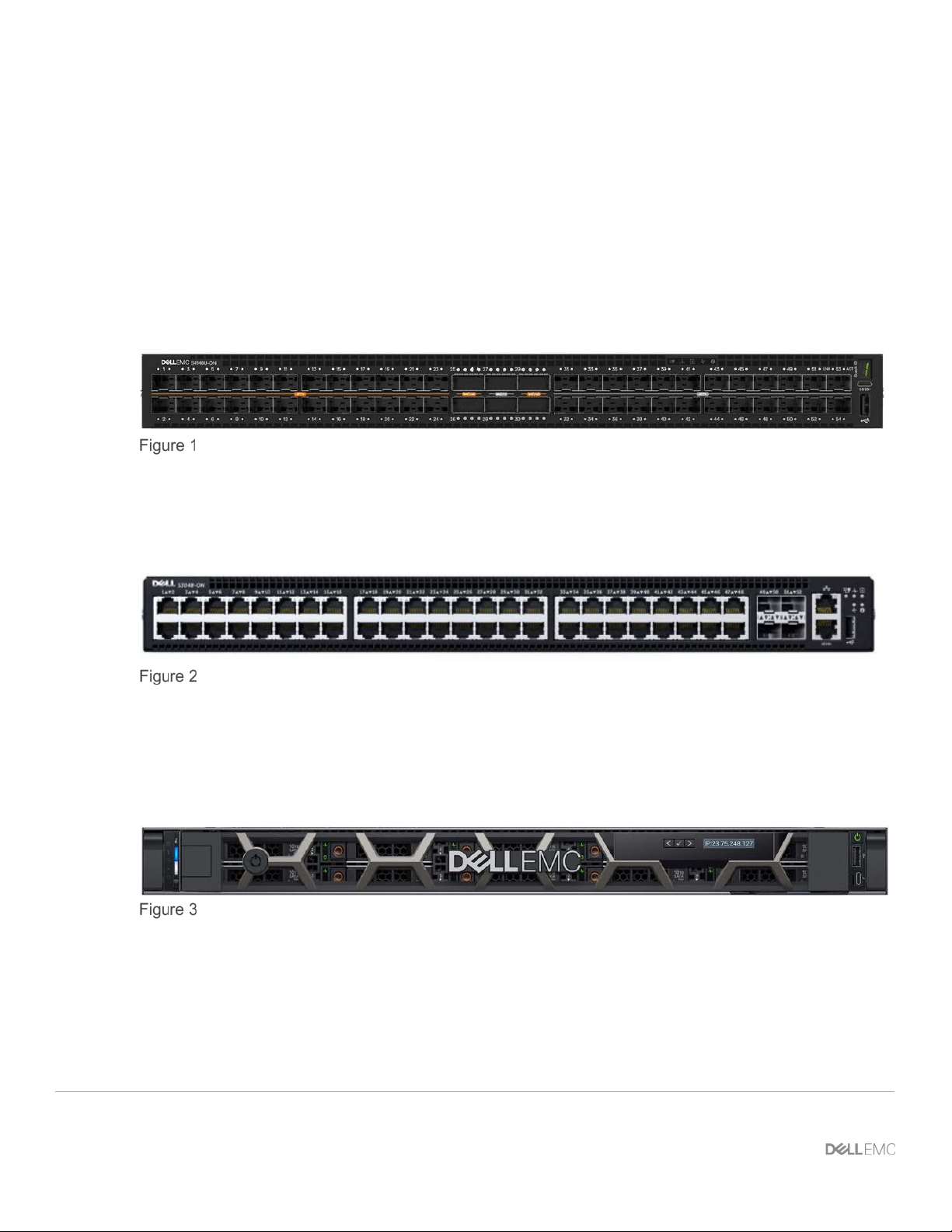
2.4 Dell EMC Unity 500F storage array
The Unity 500F storage platform delivers all-flash storage with up to 8PB raw capacity. It has concurrent
support for NAS, iSCSI, and FC protocols. The Disk Processing Enclosure (DPE) has a 2-RU form factor,
redundant Storage Processors (SPs), and supports up to twenty-five 2.5" drives. Additional 2-RU Disk Array
Enclosures (DAEs) may be added providing twenty-five additional drives each.
Dell EMC Unity 500F front view
Dell EMC Unity 500F rear view
8 Dell EMC Networking Fibre Channel Deployment with S4148U-ON in F_port Mode | version 1.0
Page 9
Rack 1
S4148U-Leaf1 S4148U-Leaf2
Unity 500F
SP A
SP B
R640-1
FC SAN A (FC ports)
LAN (E t herne t p orts )
LAN (E t herne t p orts )
VLTi (Et hernet port s)
FC SAN B (FC ports)
R640-2
Rack n
Leaf Leaf
Spine2Spine1
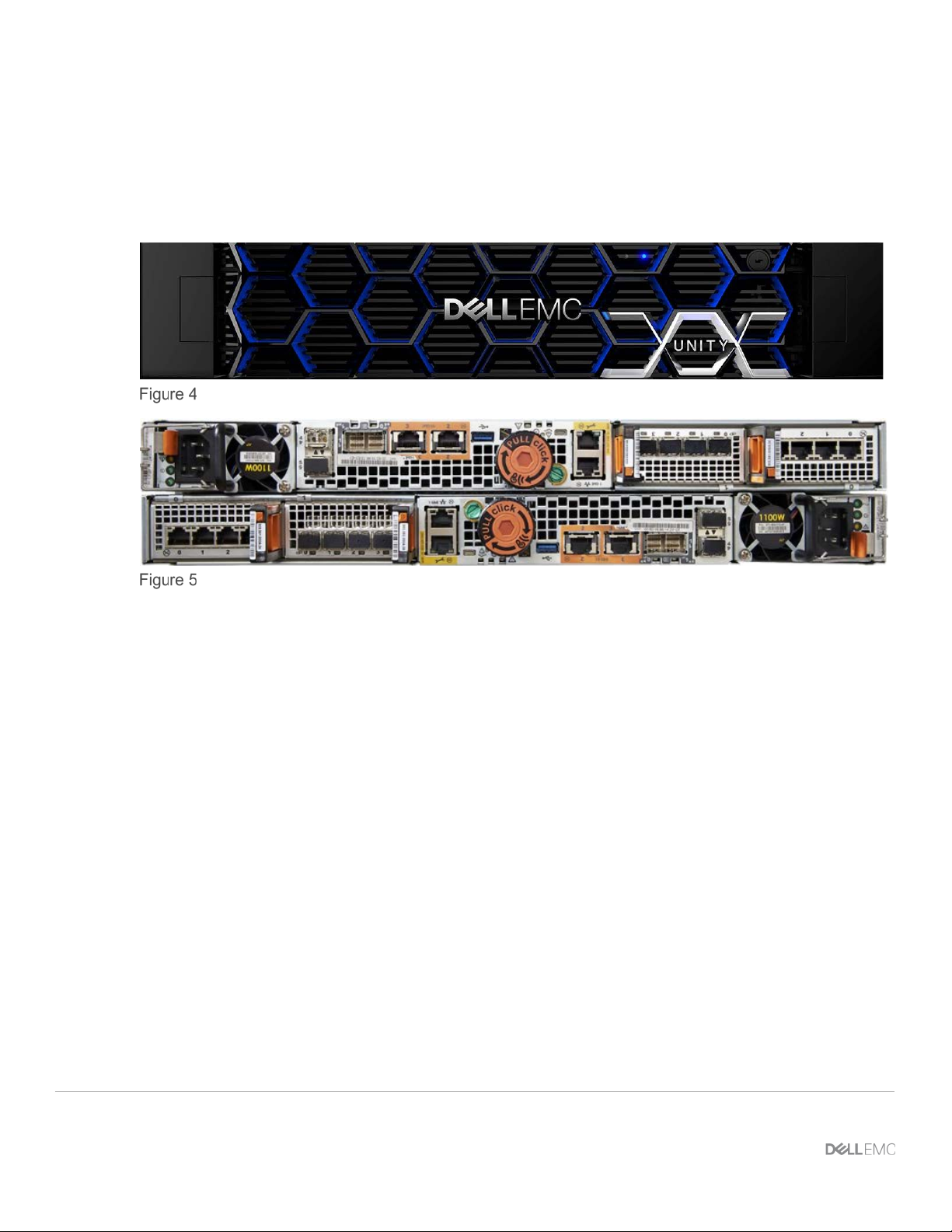
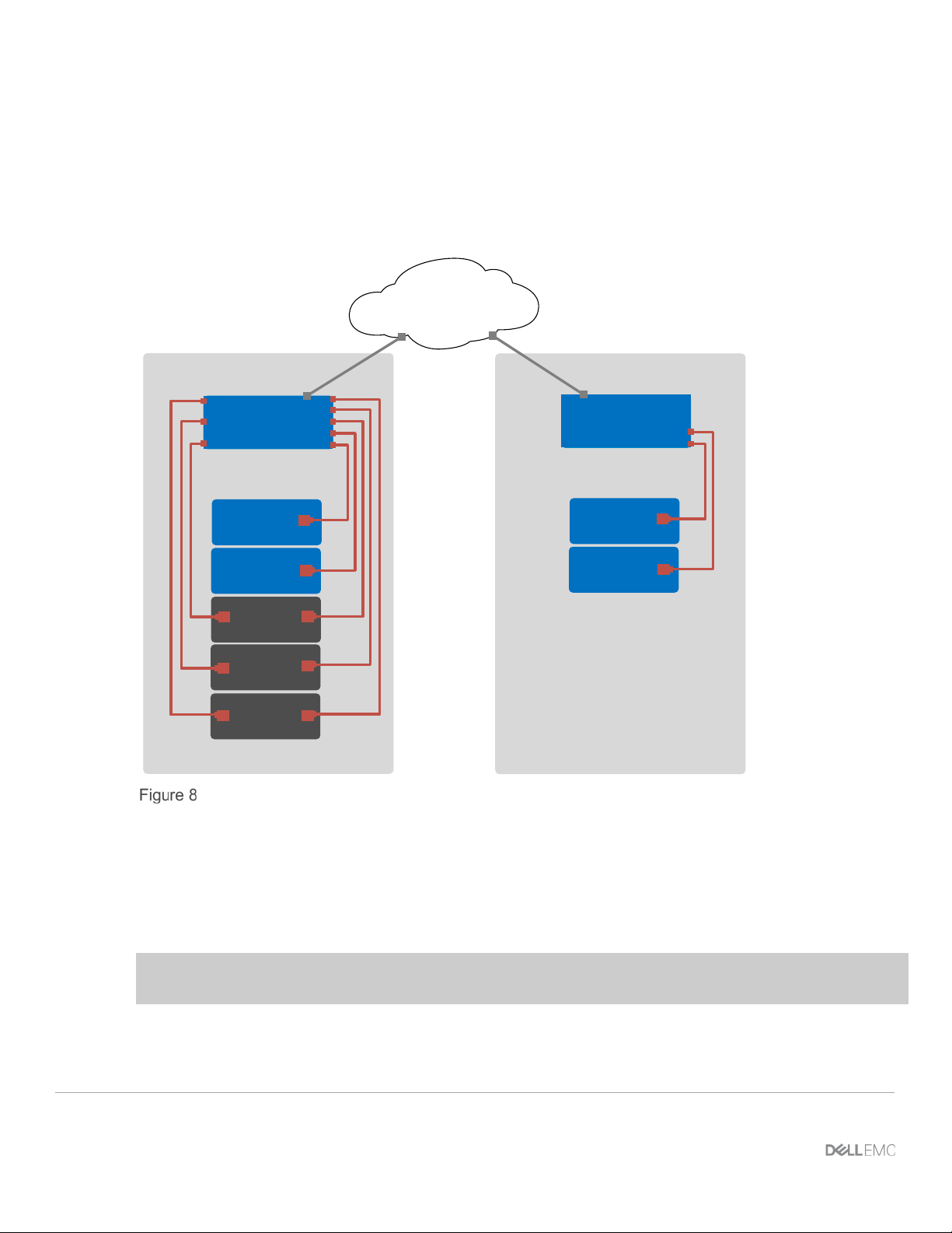
3 Topology overview
Each S4148U-ON provides universal ports that may be configured as either FC or Ethernet. The mix of FC
and Ethernet ports allows the switches to simultaneously connect directly to an FC SAN for storage traffic and
act as leafs in a leaf-spine network for production TCP/IP traffic.
Note: FC SAN traffic does not traverse the leaf-spine network, or the VLT interconnect (VLTi). FC traffic is
contained within the rack.
A combined FC SAN and le af -spine topology is shown in the diagram below.
Note: Using a leaf-spine network in the data center is considered a best practice. This document covers
configuration of the FC SAN portion of the topology above. For the leaf-spine Ethernet portion, refer to Dell
EMC Networking Layer 3 Leaf-Spine Deployment and Best Practices with OS10EE.
Combined FC SAN and leaf-spine topology
9 Dell EMC Networking Fibre Channel Deployment with S4148U-ON in F_port Mode | version 1.0
Page 10
R ack 1
S4148U-Leaf1 S4148U-Leaf2
Unity 500F
1
R640-1
SP B
SP A
0
0
1
1
FC SAN A (16Gb FC)
FC SAN B (16Gb FC)
fc5fc7fc1 fc3
fc5 fc7 fc1fc3
Leaf port numbers shown are
abbreviated, e.g., fc1/1/1 is
abbreviated as fc1.
2
R640-2
1
2
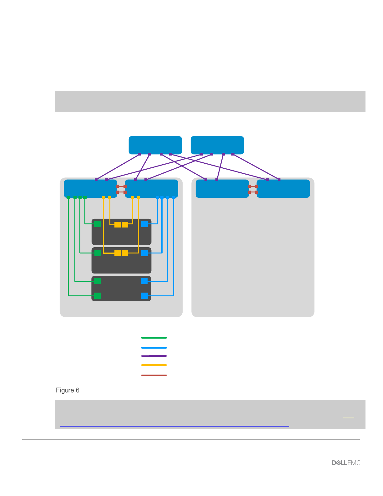
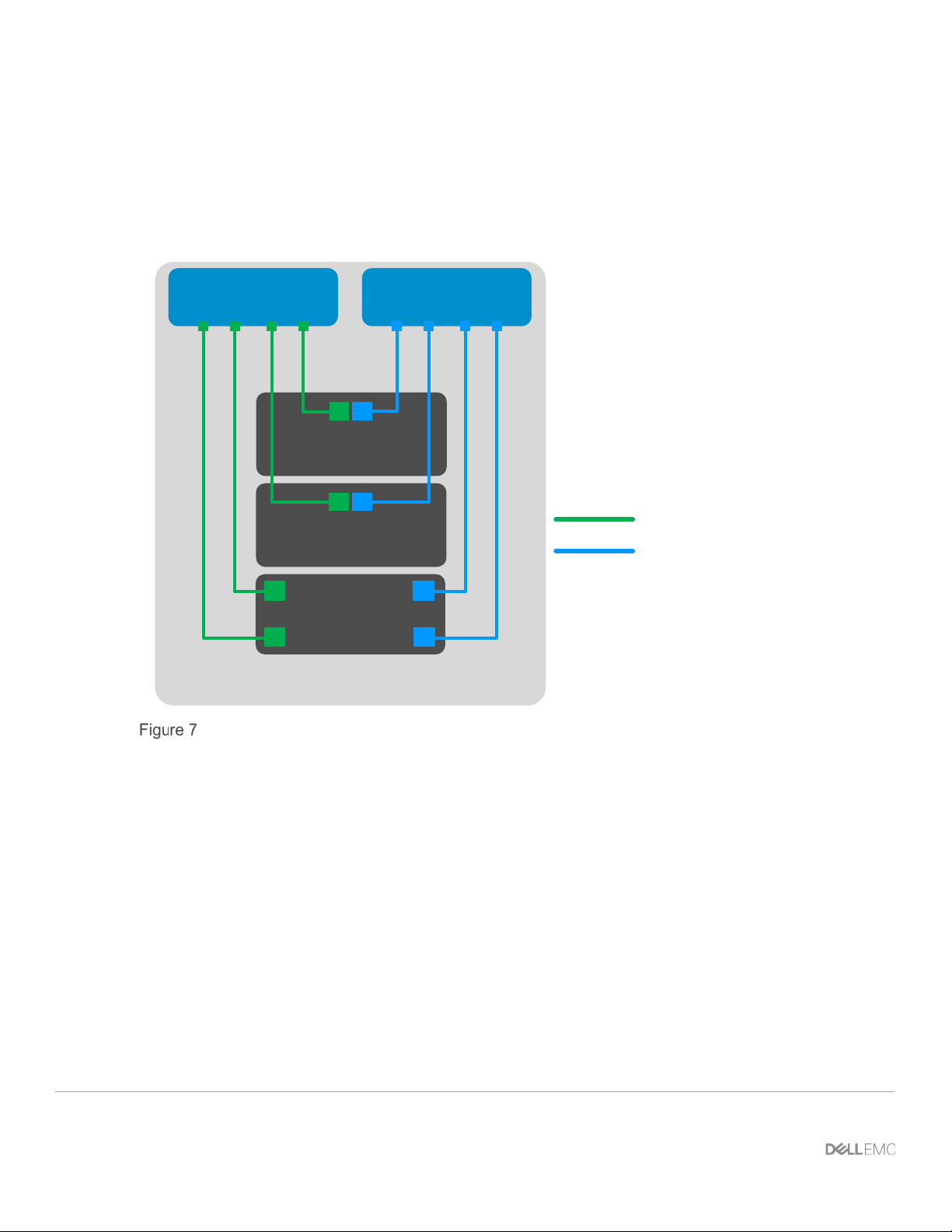
3.1 FC SAN topology detail
Each S4148U-ON switch is placed in F_port mode and acts as an FC switch. This enables direct connections
to N_port devices such as FC storage and server FC HBAs w ithout the nee d for additional dedicated FC
switches.
The FC SAN topology used in this guide is shown in Figure 7.
FC SAN topology
Each PowerEdge R640 server in this deployment contains one QLogic QLE2662 FC HBA with two 16Gb FC
ports. Each HBA port is connected to an FC port on one S4148U-ON as shown.
The Unity 500F storage array contains redundant storage proc ess or s , SP A and SP B. 16Gb FC ports from
the Unity SPs are directly connected to FC ports on the S4148U-ON switches as shown.
10 Dell EMC Networking Fibre Channel Deployment with S4148U-ON in F_port Mode | version 1.0
.
Page 11
S3048
-ON
R640-2
R640-1
S4148U-
Leaf1
S4148U-
Leaf2
OOB
Management
Network
Rack n
Rack 1
Unity
500F
S3048-ON
Z9100Spine1
Z9100-
Spine2
3.2 OOB management network
The out-of-band (OOB) management network is an isolated network for management traffic only. It is used by
administrators to remotely configure and manage servers, switches, and storage devices. Production traffic
initiated by the network end users does not traverse the management network.
An S3048-ON switch is installed at the top of each rack for OOB management connections as shown.
OOB management network connections
Four 10GbE SFP+ ports are available on each S3048-ON switch for use as uplinks to the OOB management
network core. Downstream connections to servers, switches, and storage devices are 1GbE BASE-T.
11 Dell EMC Networking Fibre Channel Deployment with S4148U-ON in F_port Mode | version 1.0
The dedicated OOB management port of each leaf and spine switch is used for these connections. Each
PowerEdge R640 server has two connections to the S3048-ON: the server’s iDRAC port and a 1GbE NIC
that is used for ESXi host management .
Note: For this deployment example, each server’s ESXi management connection is made using one of the
two QLogic 57800 1GbE BASE-T ports on the rNDC.
The Unity 500F storage array has two dedicated management ports: one for SP A and one for SP B. Both are
connected to the S3048-ON.
Page 12

4 Preparation
Note: Exact iDRAC steps in this section may vary depending on hardware, software and browser versions
used. See the PowerEdge server documentation for steps to connect to the iDRAC.
4.1 Reset server FC HBAs to factory defaults
Note: Resetting to defaults is only necessary if installe d FC HBAs have been modified from their factory
default settings.
1. Connect to the server's iDRAC in a web browser and launch the virtual console.
2. In the virtual console, from the Next Boot menu, select BIO S Set u p.
3. Reboot the server.
4. From the System Setup Main Menu, select Device S et tin gs.
5. From the D ev ice Sett ing s page, select the first FC adapter port.
6. From the Main Configuration Page, click the Default button followed by Yes to load the default
settings. Click OK.
7. Click Finish.
8. Click Yes to save changes. Click OK.
9. Repeat steps 5-8 for the second FC adapter port.
10. Repeat steps 1-9 for remaining servers.
4.2 Determine FC HBA port WWPNs
The PowerEdge R640 server's FC HBA World Wide Port Names (WWPNs) are used for FC zone
configuration. WWPNs may be determined using the iDRAC as follows:
1. Connect to the first server's iDRAC in a web browser and log in.
2. Select System > Network Devices.
3. Under Network Devices, click on the FC HBA. In this example, it is FC Slot 2. The FC ports ar e
displayed as shown in Figure 9:
12 Dell EMC Networking Fibre Channel Deployment with S4148U-ON in F_port Mode | version 1.0
Page 13

FC ports listed in iDRAC
4. Under Fibre Channel Ports, click the icon next to the first port to expand the details as shown:
WWPN for FC HBA port 1
5. Record the World Wide Port Name, outlined in red in F igure 10. A convenient method is to copy and
paste it into a text file. The WWPN is used in the S4148U-ON switch FC zone configuration.
13 Dell EMC Networking Fibre Channel Deployment with S4148U-ON in F_port Mode | version 1.0
Page 14

Server
Port
Switch
WWPN
R640-1
1
S4148U-Leaf1
20:01:00:0E:1E:09:A2:3A
R640-1
2
S4148U-Leaf2
20:01:00:0E:1E:09:A2:3B
R640-2
1
S4148U-Leaf1
20:01:00:0E:1E:09:B8:F6
R640-2
2
S4148U-Leaf2
20:01:00:0E:1E:09:B8:F7
6. Repeat steps 4 and 5 for FC port 2.
7. Repeat steps 1-6 for remaining servers.
The FC WWPNs used in this deployment example are sho wn in Table 1. The Switch column has been added
for reference per the cable connections in the SAN topology diagram (Figure 7).
Server HBA FC port WWPNs
14 Dell EMC Networking Fibre Channel Deployment with S4148U-ON in F_port Mode | version 1.0
Page 15

Service
processor
SP A
0
S4148U-Leaf1
50:06:01:66:47:E0:1B:19
SP A
1
S4148U-Leaf2
50:06:01:67:47:E0:1B:19
SP B
0
S4148U-Leaf1
50:06:01:6E:47:E0:1B:19
SP B
1
S4148U-Leaf2
50:06:01:6F:47:E0:1B:19
4.3 Determine Unity 500F storage array FC WWPNs
The WWPNs of FC adapters in storage arrays are also used for FC zone configuration. WWPNs on Unity
storage arrays are determined as follows:
1. Connect to the Unisphere GUI in a web browser and log in. Click the Settings icon near the top
right corner of the page.
2. In the left pane of the Settings window, select Access > Fibre Channel.
The Fibre Channel Ports page is displayed as shown in Figure 11. A zoomed-in view of the area inside
the red box is shown in Figure 12.
Unisphere Fibre Channel Ports page
Zoomed-in view of SP A and SP B WWNs on Fibre Channel Ports page
3. Two WWNs are listed for each port. The World Wide Node Name (WWNN), outlined in black,
identifies this Unity storage array (the node). It is not used in zone configuration. The WWPNs,
outlined in blue, identify the individual ports and are used for FC zoning. Record the WWPNs as
shown in Table 2. The Switch column has been added based on the physical cable connections
shown in Figure 7.
Storage array FC adapter WWPNs
Port Switch WWPN
15 Dell EMC Networking Fibre Channel Deployment with S4148U-ON in F_port Mode | version 1.0
Page 16

4.4 VMware preparation
4.4.1 VMware ESXi download and installation
Install VMware ESXi 6.5 U1 or later on each PowerEdge server. Dell EMC recommends using the latest Dell
EMC customized ESXi .iso image avai lab le on support.dell.com
server hardware are built into this image. This image is used to install ESXi via CD/DVD, a USB flash drive, or
by mounting the .iso image through the PowerEdge server’s iDRAC interface.
Each ESXi host has one 1GbE BASE-T interface connected to the OOB management network for
communication with the vCenter Serv er.
4.4.2 Install and configure VMware vCenter Server 6.5 U1
For information on the installation and configuration of vCenter Server, refer to vSphere Installation and
Setup. In this deployment, the vCenter Server communicates with ESXi hosts via the OOB management
network, and it may be located on any host accessible over this network.
4.4.3 Add ESXi hosts to vCenter Server
The vSphere Web Client is a service running on vCenter Server. In the vSphere Web Client, a data center
object named Datacenter is created for this deployment, and the two ESXi hosts are added to it.
. The correct drivers for the PowerEdge
A cluster named Rack1 is created and added to the datacenter object, and the two R640 hosts are added to
the cluster. When complete, the vSphere Web Client Hosts and Clusters tab in the Navigator pane appears
as shown in Figure 13.
Datacenter and cluster created with ESXi hosts
16 Dell EMC Networking Fibre Channel Deployment with S4148U-ON in F_port Mode | version 1.0
Page 17

5 S4148U-ON switch configuration
This section covers steps to configure the S4148U-ON leaf switches running OS10EE.
5.1 Prepare switches
5.1.1 Factory default configuration
The configuration commands in the sections that follow begin with S4148U-ON switches at their factory
default settings. Dell EMC Networking switches running OS10EE can be reset to their default configuration as
follows:
OS10# delete startup-configuration
Proceed to delete startup-configuration [confirm yes/no(default)]:y
OS10# reload
System configuration has been modified. Save? [yes/no]:n
Proceed to reboot the system? [confirm yes/no]:y
The switch reboots to its factory default configuration. Repeat on the second S4148U-ON switch.
Note: OS10EE at its default settings has Telnet disabled, SSH enabled, and the OOB management
interface configured to get its IP address via DHCP. The default username and password are both admin.
Dell EMC recommends changing the admin password to a complex password during the first login.
5.1.2 Set switch port profile
A switch port profile determines the enabled front-panel ports and supported breakout modes on Ethernet and
unified ports. Changing the profile removes the existing switch configuration, so the switch port profile is
configured first. Switch port profile-3 is used in this deployment to enable four 100GbE ports on each
S4148U-ON for the leaf-spine portion of the topology. This profile also provides twelve 16Gb FC ports for
storage connections.
Note: See OS10 Enterprise Edition User Guide Release 10.4.0E(R3) for switch-port profile options and
details.
To change the switch-por t profile from its current setting:
OS10# configure terminal
OS10(config)# switch-port-profile 1/1 profile-3
Warning: Switch port profile will be applied only after a save and reload.
All management port configurations will be retained but all other
configurations will be wiped out after the reload.
OS10(config)# exit
OS10# write memory
OS10# reload
17 Dell EMC Networking Fibre Channel Deployment with S4148U-ON in F_port Mode | version 1.0
Page 18

S4148U-Leaf1
S4148U-Leaf2
configure terminal
100.67.169.254
configure terminal
100.67.169.254
S4148U-Leaf1
S4148U-Leaf2
feature fc domain-id 100
member wwn 50:06:01:66:47:E0:1B:19
feature fc domain-id 100
member wwn 50:06:01:67:47:E0:1B:19
Proceed to reboot the system? [confirm yes/no]:y
5.2 Configure switches
After the switch port profile is set on both S4148U-ONs, the commands in the tables that follow are run to
complete the FC configuration on both switches. The port numbers used correspond to the topology diagram
shown in Figure 7.
Note: The commands in the tables below should be entered in the order shown. Switch runningconfiguration files are provided as attachments named S4148U-Leaf1.txt and S4148U-Leaf2.txt.
Configure the hostname, OOB management IP address, and OOB management default gateway.
hostname S4148U-Leaf1
interface mgmt 1/1/1
no ip address dhcp
ip address 100.67.169.31/24
no shutdown
management route 0.0.0.0/0
The feature fc domain-id domain-id command puts the switch in F_port mode. FC aliases are
configured for the server and storage adapter WWPNs from Table 1 and Table 2. Using aliases is optional,
but makes the configuration more user-friendly.
fc alias r640-1p1
member wwn 20:01:00:0E:1E:09:A2:3A
fc alias r640-2p1
member wwn 20:01:00:0E:1E:09:B8:F6
fc alias SpB-0
member wwn 50:06:01:6E:47:E0:1B:19
fc alias SpA-0
hostname S4148U-Leaf2
interface mgmt 1/1/1
no ip address dhcp
ip address 100.67.169.30/24
no shutdown
management route 0.0.0.0/0
fc alias r640-1p2
member wwn 20:01:00:0E:1E:09:A2:3B
fc alias r640-2p2
member wwn 20:01:00:0E:1E:09:B8:F7
fc alias SpB-1
member wwn 50:06:01:6F:47:E0:1B:19
fc alias SpA-1
18 Dell EMC Networking Fibre Channel Deployment with S4148U-ON in F_port Mode | version 1.0
Page 19

S4148U-Leaf1
S4148U-Leaf2
fc zone r640-1p1zone
member alias-name SpA-0
fc zone r640-1p2zone
member alias-name SpA-1
S4148U-Leaf1
S4148U-Leaf2
fc zoneset zoneset1
exit
fc zoneset zoneset1
exit
S4148U-Leaf1
S4148U-Leaf2
interface vlan 1002
zoneset activate zoneset1
interface vlan 1002
zoneset activate zoneset1
Server and storage adapter WWPNs, or their aliases, are combined into zones to allow communication
between devices in the same zone. Dell EMC recommends single-initiator zonin g. In other words, no more
than one server HBA port per zone. For high availability, each server HBA port should be zone d to at least
one port from SP A and one port from SP B.
In this deployment, one zone is created for each server HBA port. The zone contains the server port and the
two storage processor ports connected to the same S4148U-ON.
member alias-name r640-1p1
member alias-name SpB-0
member alias-name SpA-0
fc zone r640-2p1zone
member alias-name r640-2p1
member alias-name SpB-0
member alias-name r640-1p2
member alias-name SpB-1
member alias-name SpA-1
fc zone r640-2p2zone
member alias-name r640-2p2
member alias-name SpB-1
A zone set is a collect ion of zones. A zone set named zoneset1 is created on each switch, and the zones are
added to it.
Note: Multiple zone sets may be configured on a switch, but only one zone set can be active at any time.
member r640-1p1zone
member r640-2p1zone
member r640-1p2zone
member r640-2p2zone
Create the FCoE VLAN, vfabric, FCoE map, and activate the zone set. In this deployment, the FCoE VLAN is
set to 1002, the vfabric ID is set to 100 (valid range is 1-255) , and the fcmap is set to 0xEFC64 (valid range is
0xEFC00-0xEFCFF).
Note: The FCoE VLAN and FCoE map are used intern ally by the switch to forward FC traffic, even if FCoE
is not used by nodes connected to the switch.
vfabric 100
vlan 1002
fcoe fcmap 0xEFC64
19 Dell EMC Networking Fibre Channel Deployment with S4148U-ON in F_port Mode | version 1.0
vfabric 100
vlan 1002
fcoe fcmap 0xEFC64
Page 20

S4148U-Leaf1
S4148U-Leaf2
port-group 1/1/1
write memory
port-group 1/1/1
write memory
Note: If changes are subsequently made to aliases, zones, or zone sets, the zone set must be reactivated
for the changes to take effect. This is done with the following command sequence:
S4148U-Leaf1# configure terminal
S4148U-Leaf1(config)# vfabric vfabric_number
S4148U-Leaf1(conf-vfabric-100)# zoneset activate zoneset_name
Put enough unified ports in 16Gb FC mode for connections to the FC storage array. In this deployment
example, four FC ports per S4148U-ON switch are used. In switch port profile-3, unified port groups 1 and 2
(entered as 1/1/1 and 1/1/2) provide two 16Gb FC interfaces each.
Note: For more information on mapping ports to switch profiles and port groups, see OS10 Ent er pris e
Edition User Guide Release 10.4.0E(R3), p.83-85.
Add the server and storage Fibre Channel interfaces to vfabric 100.
Finally, exit configuration mode and save the configuration with the end and write memory commands.
mode fc 16g-2x
port-group 1/1/2
mode fc 16g-2x
interface fibrechannel 1/1/1
description "To SPB"
no shutdown
vfabric 100
interface fibrechannel 1/1/3
description "To SPA"
no shutdown
vfabric 100
interface fibrechannel 1/1/5
description "To Server 1"
no shutdown
vfabric 100
interface fibrechannel 1/1/7
description "To Server 2"
no shutdown
vfabric 100
end
mode fc 16g-2x
port-group 1/1/2
mode fc 16g-2x
interface fibrechannel 1/1/1
description "To SPB"
no shutdown
vfabric 100
interface fibrechannel 1/1/3
description "To SPA"
no shutdown
vfabric 100
interface fibrechannel 1/1/5
description "To Server 1"
no shutdown
vfabric 100
interface fibrechannel 1/1/7
description "To Server 2"
no shutdown
vfabric 100
end
20 Dell EMC Networking Fibre Channel Deployment with S4148U-ON in F_port Mode | version 1.0
Page 21

6 S4148U-ON validation
After connected devices are configured, many commands are available to validate the network configuration.
This section provides a list of the most common commands and their output for this topology.
Note: The commands and output shown below are for S4148U-Leaf1. The output for S4148U-Leaf2 is
similar. For additional commands and output related to the leaf-spine portion of the topology, such as VLT,
BGP, etc., see Dell EMC Networking Layer 3 Leaf-Spine Deployment and Best Practices with OS10EE.
6.1 show interface status
The show interface status | grep up command is used to verify required interfaces are up, and
links are established at their appropriate speeds.
S4148U-Leaf1# show interface status | grep up
Port Description Status Speed Duplex Mode Vlan Tagged-Vlans
Fc 1/1/1 To SPB up 16G auto Fc 1/1/3 To SPA up 16G auto Fc 1/1/5 To Server 1 up 16G auto Fc 1/1/7 To Server 2 up 16G auto -
6.2 show fc switch
The show fc switch command verifies the switch is in F_Port mode for FC traffic.
S4148U-Leaf1# show fc switch
Switch Mode : FPORT
Switch WWN : 10:00:e4:f0:04:6b:04:42
6.3 show fc ns switch
The show fc ns switch command shows all device ports logged into the fabric. In this deployment, four
ports are logged in to each switch: two storage ports and two server ports.
S4148U-Leaf1# show fc ns switch
Total number of devices = 4
Switch Name 10:00:e4:f0:04:6b:04:42
Domain Id 100
Switch Port fibrechannel1/1/1
FC-Id 64:04:00
Port Name 50:06:01:6e:47:e0:1b:19
Node Name 50:06:01:60:c7:e0:1b:19
Class of Service 8
Symbolic Port Name UNITY::::SPB10::FC::::::
21 Dell EMC Networking Fibre Channel Deployment with S4148U-ON in F_port Mode | version 1.0
Page 22

Symbolic Node Name UNITY::::SPA::FC::::::
Port Type N_PORT
Registered with NameServer Yes
Registered for SCN Yes
Switch Name 10:00:e4:f0:04:6b:04:42
Domain Id 100
Switch Port fibrechannel1/1/3
FC-Id 64:0c:00
Port Name 50:06:01:66:47:e0:1b:19
Node Name 50:06:01:60:c7:e0:1b:19
Class of Service 8
Symbolic Port Name UNITY::::SPA10::FC::::::
Symbolic Node Name UNITY::::SPA::FC::::::
Port Type N_PORT
Registered with NameServer Yes
Registered for SCN Yes
Switch Name 10:00:e4:f0:04:6b:04:42
Domain Id 100
Switch Port fibrechannel1/1/5
FC-Id 64:14:00
Port Name 20:01:00:0e:1e:09:a2:3a
Node Name 20:00:00:0e:1e:09:a2:3a
Class of Service 8
Symbolic Port Name
Symbolic Node Name QLE2662 FW:v8.05.63 DVR:v2.1.57.0
Port Type N_PORT
Registered with NameServer Yes
Registered for SCN Yes
Switch Name 10:00:e4:f0:04:6b:04:42
Domain Id 100
Switch Port fibrechannel1/1/7
FC-Id 64:1c:00
Port Name 20:01:00:0e:1e:09:b8:f6
Node Name 20:00:00:0e:1e:09:b8:f6
Class of Service 8
Symbolic Port Name
Symbolic Node Name QLE2662 FW:v8.05.63 DVR:v2.1.57.0
Port Type N_PORT
Registered with NameServer Yes
Registered for SCN Yes
Note: For condensed output, use the show fc ns switch brief command.
22 Dell EMC Networking Fibre Channel Deployment with S4148U-ON in F_port Mode | version 1.0
Page 23

6.4 show fc zoneset active
The show fc zoneset active command shows the zones and zone members in the active zone set.
Members logged into the fabric are shown with an asterisk (*).
S4148U-Leaf1# show fc zoneset active
vFabric id: 100
Active Zoneset: zoneset1
ZoneName ZoneMember
===========================================================
r640-1p1zone *20:01:00:0e:1e:09:a2:3a
*50:06:01:66:47:e0:1b:19
*50:06:01:6e:47:e0:1b:19
r640-2p1zone *20:01:00:0e:1e:09:b8:f6
*50:06:01:66:47:e0:1b:19
*50:06:01:6e:47:e0:1b:19
6.5 show vfabric
The show vfabric command output provides a variety of information including the default zone mode, the
active zone set, and interfaces that are members of the vfabric.
S4148U-Leaf1# show vfabric
Fabric Name
Fabric Type FPORT
Fabric Id 100
Vlan Id 1002
FC-MAP 0xEFC64
Vlan priority 3
FCF Priority 128
FKA-Adv-Period Enabled,8
Config-State ACTIVE
Oper-State UP
==========================================
Switch Config Parameters
==========================================
Domain ID 100
==========================================
Switch Zoning Parameters
==========================================
Default Zone Mode: Deny
Active ZoneSet: zoneset1
==========================================
Members
fibrechannel1/1/1
23 Dell EMC Networking Fibre Channel Deployment with S4148U-ON in F_port Mode | version 1.0
Page 24

fibrechannel1/1/3
fibrechannel1/1/5
fibrechannel1/1/7
==========================================
Note: By default, the Default Zone Mode is set to Deny. This setting denies access between FC nodes
except those in the same zone of the active zone set. To allow access between FC nodes in the absence of
an active zone set, change the Default Zone Mode to Allow with the following command sequence:
S4148U-Leaf1# configure terminal
S4148U-Leaf1(config)# vfabric vfabric_number
S4148U-Leaf1(conf-vfabric-100)# zone default-zone permit
24 Dell EMC Networking Fibre Channel Deployment with S4148U-ON in F_port Mode | version 1.0
Page 25

7 Configure Unity FC storage
This section covers configuration of a Dell EMC Unity 500F storage array. Refer to the storage system
documentation for other FC storage devices.
7.1 Create a storage pool
1. Connect to the Unisphere GUI in a web browser and log in.
2. In the left pane under STORAGE, select Pools.
3. Click the icon. In the Create Pool dialog box, provide a Name and click Next.
4. Select appropriate storage tiers and RAID configuration for the pool. Click Next.
5. Under Select Amount of Storage, select the number of drives section. The total number of drives
and the total capacity will be displayed next to Totals. Click Next.
6. The Capability Profile Name section is optional. Click Next.
7. Review selections on the Summary page and click Finish to create the pool. Once the Overall
status shows 100%, click Close.
8. The pool is displayed on the STORAGE > Pools page as shown in Figure 14.
Storage pool created
25 Dell EMC Networking Fibre Channel Deployment with S4148U-ON in F_port Mode | version 1.0
Page 26

7.2 Add ESXi hosts
1. In the Unisphere left pane under ACCESS, select VMware.
2. On the vCenters tab, click the icon to open the Add vCenter dialog box.
3. Enter the Network Name or Address of the vCenter server. Enter the vCenter User Name and
Password and click Find.
4. A list of discovered ESXi hosts is displayed. Select the applicable hosts and click Next.
5. A VMware API for Storage Awareness (VASA) Provider is not used in this example. Click Next.
6. On the Summary page, review the ESXi Hosts to be added. Click Finish.
7. When the Overall status shows 100% Completed, click Close.
8. The vCenter server is displayed as shown in Figure 15.
vCenter server added to Unisphere
9. The list of added ESXi hosts is displayed on the ESXi Hosts tab, as shown in Figure 16.
ESXi Hosts added to Unisphere
Note: Additional hosts may be added as needed on the ESXi Hosts tab. Click the icon, enter the
credentials for the vCenter Server or ESXi host, and follow the prompts.
7.3 Create LUNs and configure host access
1. In the Unisphere left pane under STORAGE, select Block.
2. On the LUNs tab, click the icon to open the Create LUNs dialog box.
3. On the Configure LUN(s) page, select the Number of LUNs. Provide a Name and select the
Storage Pool. Modify the Size as required and click Next.
4. On the Access page, click the icon and select host(s) to be granted access to the LUN. Click OK
> Next.
26 Dell EMC Networking Fibre Channel Deployment with S4148U-ON in F_port Mode | version 1.0
Page 27

5. On the Snapshot page, leave settings at their defaults and click Next.
6. On the Replication page, leave settings at their defaults and click Next.
7. On the Summary page, review the details and click Finish to create the LUN.
8. On the Results page, click Close when Overall statu s shows 100% Completed.
The newly created LUN is now visible on the LUNs tab as shown in Figure 17. In this example, a LUN named
FC-80GB that is 80GB in size has been created.
LUN Created
Create additional LUNs and grant access (map) to hosts as needed.
Note: To modify host access at any time, check the box next to the LUN to select it. Click the icon, and
select the Host Access tab.
27 Dell EMC Networking Fibre Channel Deployment with S4148U-ON in F_port Mode | version 1.0
Page 28

8 Configure storage on ESXi hosts
In this section, the example LUN created on the storage array is used to create a datastore on an ESXi host.
The datastore is used to create a virtual disk on a virtual machine (VM) residing on the ESXi host. This
process may be repeated as needed for additional LUNs, hosts, and VMs.
8.1 Rescan storage
1. In the vSphere Web Client, go to Home > Hosts and Clusters.
2. In the Navigator pane, select an ESXi host with LUN access configured on the FC storage array.
3. In the center pane, select Configure > Storage Adapters.
4. Select host's first FC adapter, vmhba4 in this example, and click the icon to rescan storage.
5. The LUN on the storage array mapped to this host appears under Adapter Details on the Devices
tab as shown in Figure 18.
LUN visible to ESXi host
6. Repeat for host's second adapter, vmhba5 in this example. The LUN information on the Adapter
Details > Devices tab is identical to the first adapter.
7. Select the first storage adapter, e.g., vmhba4, then select the Adapter Details > Paths tab as shown
in Figure 19. The target, LUN number (e.g., LUN 0) and path status are shown. The target field
includes the two active storage WWPNs connected to vmhba4. The status field is marked either
Active or Active (I/O) for each path.
28 Dell EMC Networking Fibre Channel Deployment with S4148U-ON in F_port Mode | version 1.0
Page 29

Adapter Details - Paths tab
The Paths tab includes similar information for the host’s second storage adapter.
8.2 Create a datastore
In this section, a datastore that uses the Unity LUN is created on the ESXi host.
To create the datastore:
1. In the vSphere Web Client, go to Home > Hosts and Clusters.
2. In the Navigator pane, right-click on the ESXi host and select Storage > New Datastore.
3. In the New Datastore window, leave the Type set to VMFS and click Next.
4. The Name and device selection page appears as shown in Figure 20. In this example, the 80GB
LUN mapped to this host appears in the list of devices.
Name and device selection page
5. Provide a Datastore name, e.g., Unity 80GB LUN, select the LUN in the list, a nd c lic k Next.
6. Select the VMFS version. For this guide, it is left at its default setting, VMFS 5. Click Next.
7. Leave the Partition configuration at its default settings and click Next > Finish to create the
datastore.
The datastore is now accessible by selecting the host in the Navigator pane. Select the Configure tab >
Storage > Datastores as shown in Figure 21.
29 Dell EMC Networking Fibre Channel Deployment with S4148U-ON in F_port Mode | version 1.0
Page 30

Datastore configured
The datastore is also accessible by going to Home > Storage. It is listed under the Datacenter object in the
Navigator pane.
8.3 Create a virtual disk
Note: Virtual machine guest operating system deployment steps are not included in this document. For
instructions, see the VMware vSphere 6.5 Documentation. Guest operating systems can be any supported
by ESXi 6.5. VMs should be deployed before proceeding with this section.
In this example, the E SX i h ost with th e datastore configured in the previous section contains a VM named
VM1 that is running a Windows Server guest OS.
To create a virtual disk on VM1 using the datastore:
1. Go to Home > Hosts and Clusters.
2. In the Navigator pane, right click on VM1 and select Edit Settings.
3. Next to New Device, select New Hard Disk and click Add.
4. Click the icon next to New Hard Disk to view the configuration options.
5. Next to Location, select Browse. Select the previously configured datastore, e.g., Unity 80GB LUN,
and click OK. The screen looks similar to Figure 22.
30 Dell EMC Networking Fibre Channel Deployment with S4148U-ON in F_port Mode | version 1.0
Page 31

New hard disk configuration options
6. Next to New Hard disk, set the size in GB less than or equal to the Maximum size shown on the line
below. The size is set to 40 GB in this example.
7. Click OK to close the Edit Settings window and create the virtual disk.
31 Dell EMC Networking Fibre Channel Deployment with S4148U-ON in F_port Mode | version 1.0
Page 32

8.4 Configure the virtual disk
Note: The following example is applicable for VMs running Windows Server 2008, 2012, or 2016. See the
operating system documentation to configure virtual disks on other supported guest operating systems.
1. Power on the VM and log in to the Windows Server guest OS.
2. In Windows, go to Server Manager > Tools > Computer Management > Storage > Disk
Management.
Note: If an Initialize Disk window appears, select OK to initialize now, or Cancel to initialize in step 5.
3. If the new disk is not present in the list, right click on Disk Management and select Rescan Disks.
4. The new hard disk appears in the list (Disk 1 in F ig ure 23).
Windows Server Disk Management utility
5. If the disk is not initialized or online, right-click in the box containing the Disk #, e.g., Disk 1 and use
the menu options to bring the disk online and initialize it.
6. Continue using the Disk Management application to format the disk.
32 Dell EMC Networking Fibre Channel Deployment with S4148U-ON in F_port Mode | version 1.0
Page 33

Qty
Item
OS Version
2
Dell EMC Networking S4148U-ON leaf switches
10.4.0E(R3P2)
1
Dell EMC Networking S3048-ON management switch
10.4.0E(R3P2)
Qty per
server
1
Intel Xeon Gold 6126 CPU @ 2.60GHz, 12 cores
- 6 8GB DDR4 DIMMs (48GB total)
- 1 120GB SATA SSD
- 1 PERC H330 Mini Stora ge C ontro ll er
25.5.3.0005
1
QLogic QLE2662 2x16Gb FC HBA (Low Profile)
14.04.09
1
QLogic 57800 rNDC - 2x10GbE SFP+ ports plus 2x1GbE BASET ports
14.02.12
-
BIOS
1.3.7
-
iDRAC with Lifecycle Controller
3.00.00.00
Qty
Item
Firmware Version
1
Unity 500F
4.3.0.1522077968
A Validated components
The following tables include the hardware, software, and firmware used to configure and validate the
examples in this guide.
A.1 Switches
Switches and OS versions
A.2 PowerEdge R640 servers
R640 server components
A.3 Storage
Storage firmware version
Item Firmware version
33 Dell EMC Networking Fibre Channel Deployment with S4148U-ON in F_port Mode | version 1.0
Page 34

Item
Version
VMware ESXi
6.5 U1 - Dell EMC customized image version A10, build 7967591
VMware vCenter Server Appliance
6.5 Update 1d – build 73 12 210 (Includes vSphere Web Client)
A.4 VMware software
The following table lists the VMware software components used to validate the examples in this guide.
VMware software versio ns
A.5 VMware licenses
The vCenter Server is licensed by instance. Other VMware product licenses are allocated based on the
number of CPU sockets populated in the participating hosts.
Required licenses for the topology built in this guide are as follows:
• VMware vSphere 6 Enterprise Plus – 2 CPUs
• vCenter 6 Server Standard – 1 instance
34 Dell EMC Networking Fibre Channel Deployment with S4148U-ON in F_port Mode | version 1.0
Page 35

B Technical supp or t and resources
Dell TechCenter is an online technical community where IT professionals have access to numerous resources
for Dell EMC software, hardware, and services.
B.1 Dell EMC product manuals and technical guides
Manuals and documentation for Dell EMC Networking S3048-ON
Manuals and documentation for Dell EMC Networking S4148U-ON
Manuals and documentatio n for Dell EMC Power Edg e R640
OS10 Enterprise Edition User Guide Release 10.4.0E(R3)
Dell EMC Unity Technical Documentation
Dell EMC TechCenter Networking Guides
Dell EMC Networking Layer 3 Leaf-Spine Deployment and Best Practices with OS10EE
B.2 VMware product manuals and technical guides
VMware vSphere Documentation
vSphere Installation and Setup – This document includes ESXi 6.5 and vCenter Server 6.5.
VMware Compatibility Guide
35 Dell EMC Networking Fibre Channel Deployment with S4148U-ON in F_port Mode | version 1.0
Page 36

Support Contact Information
Web: http://www.dell.com/support
C Support and feedback
Contacting Technical Support
Feedback for this document
We encourage readers to provide feedback on the quality and usefulness of this publication by sending an
email to Dell_Networking_Solutions@Dell.com
Telephone: USA: 1-800-945-3355
.
36 Dell EMC Networking Fibre Channel Deployment with S4148U-ON in F_port Mode | version 1.0
 Loading...