

Page 1

Open Networking Hardware Diagnostic Guide
June 2018
Page 2

Notes, cautions, and warnings
NOTE: A NOTE indicates important information that helps you make better use of your computer.
CAUTION: A CAUTION indicates either potential damage to hardware or loss of data and tells you how to avoid the problem.
WARNING: A WARNING indicates a potential for property damage, personal injury, or death.
Copyright © 2018 Dell Inc. or its subsidiaries. All rights reserved. Dell, EMC, and other trademarks are trademarks of Dell Inc. or its subsidiaries. Other
trademarks may be trademarks of their respective owners.
2018 - 06
Rev. A05
Page 3

Contents
1 About this guide............................................................................................................................................. 7
Notices.................................................................................................................................................................................7
Related documents............................................................................................................................................................ 7
2 ONIE and Dell EMC OS installation instructions.............................................................................................8
ONIE expansion.................................................................................................................................................................. 8
DIAG-OS installation.......................................................................................................................................................... 8
ONIE and DIAG OS installation.........................................................................................................................................9
ONIE service discovery and OS installation....................................................................................................................9
Installation ONIE from BIOS............................................................................................................................................10
ONIE UEFI-based installation using USB.................................................................................................................10
3 ONIE overview............................................................................................................................................. 16
ONIE expansion.................................................................................................................................................................16
Boot processes................................................................................................................................................................. 16
POST............................................................................................................................................................................16
Capture support data from ONIE............................................................................................................................. 16
Change default grub boot entry................................................................................................................................17
View system information..................................................................................................................................................17
4 Dell EMC DIAG OS....................................................................................................................................... 19
Diagnostic package download.........................................................................................................................................19
Diagnostic test suite.................................................................................................................................................. 22
View DIAG versions..........................................................................................................................................................22
View CPLD versions........................................................................................................................................................ 22
Install or upgrade DIAG tools.......................................................................................................................................... 23
Restore factory defaults..................................................................................................................................................23
5 Dell EMC DAIG-OS tools............................................................................................................................. 25
Diagnostic tools................................................................................................................................................................25
edatool...............................................................................................................................................................................26
Tests............................................................................................................................................................................ 26
CLI options..................................................................................................................................................................26
Output......................................................................................................................................................................... 26
Verbose mode.............................................................................................................................................................28
cpldupgradetool................................................................................................................................................................29
Tests............................................................................................................................................................................ 29
CLI options..................................................................................................................................................................29
Output.........................................................................................................................................................................30
cputool...............................................................................................................................................................................30
Tests............................................................................................................................................................................ 30
CLI options..................................................................................................................................................................30
Contents
3
Page 4

Output..........................................................................................................................................................................31
eepromtool........................................................................................................................................................................32
Tests............................................................................................................................................................................ 32
CLI options..................................................................................................................................................................32
Output......................................................................................................................................................................... 33
ethtool............................................................................................................................................................................... 35
fantool............................................................................................................................................................................... 35
Tests............................................................................................................................................................................ 35
CLI options..................................................................................................................................................................35
OutputTest output.....................................................................................................................................................36
ashrom.............................................................................................................................................................................37
gpiotool..............................................................................................................................................................................38
CLI options..................................................................................................................................................................38
Output......................................................................................................................................................................... 38
list output....................................................................................................................................................................38
get output...................................................................................................................................................................39
set output................................................................................................................................................................... 39
i2ctool................................................................................................................................................................................39
Tests............................................................................................................................................................................ 39
CLI options..................................................................................................................................................................39
Outputscan Output................................................................................................................................................... 40
test Output..................................................................................................................................................................41
read Output................................................................................................................................................................ 42
write Output............................................................................................................................................................... 42
ledtool................................................................................................................................................................................42
Tests............................................................................................................................................................................ 42
CLI options..................................................................................................................................................................43
Outputlist output........................................................................................................................................................44
get Output.................................................................................................................................................................. 44
lpctool................................................................................................................................................................................45
CLI options..................................................................................................................................................................45
OutputRead output................................................................................................................................................... 45
Write output............................................................................................................................................................... 45
memtool............................................................................................................................................................................ 45
Tests............................................................................................................................................................................ 46
CLI options..................................................................................................................................................................46
OutputList output...................................................................................................................................................... 47
Info output.................................................................................................................................................................. 48
Test output................................................................................................................................................................. 49
Read output................................................................................................................................................................49
Write output............................................................................................................................................................... 49
Constraints..................................................................................................................................................................49
Data ow.....................................................................................................................................................................49
nputool.............................................................................................................................................................................. 49
Tests............................................................................................................................................................................ 50
Contents
4
Page 5

CLI options..................................................................................................................................................................50
nvramtool..........................................................................................................................................................................55
Tests............................................................................................................................................................................ 55
CLI option................................................................................................................................................................... 55
OutputRead outputWrite output............................................................................................................................. 55
opticstool.......................................................................................................................................................................... 56
Tests............................................................................................................................................................................ 56
CLI options..................................................................................................................................................................56
Outputshow=brief outputshow outputshow --int=interface # output...............................................................57
pcitool................................................................................................................................................................................60
Tests............................................................................................................................................................................ 60
CLI options..................................................................................................................................................................60
Outputscan outputtest outputshow output............................................................................................................61
phytool...............................................................................................................................................................................64
Tests............................................................................................................................................................................ 64
CLI optionsOutput..................................................................................................................................................... 64
pltool..................................................................................................................................................................................66
Tests............................................................................................................................................................................ 66
CLI options..................................................................................................................................................................66
OutputList outputListdevicenames outputRead outputWrite outputTest output............................................. 67
psutool...............................................................................................................................................................................68
Tests............................................................................................................................................................................ 68
CLI optionstest option...............................................................................................................................................68
rtctool................................................................................................................................................................................ 70
Tests.............................................................................................................................................................................70
CLI options..................................................................................................................................................................70
smartctl.............................................................................................................................................................................. 71
smarttool............................................................................................................................................................................71
SMF upgrade binariesCLI options.............................................................................................................................71
SMF MSS upgrade.................................................................................................................................................... 72
Upgrading SMF FPGA............................................................................................................................................... 74
smbiostool......................................................................................................................................................................... 76
CLI options..................................................................................................................................................................76
Output......................................................................................................................................................................... 77
storagetool........................................................................................................................................................................ 77
Tests.............................................................................................................................................................................77
CLI options.................................................................................................................................................................. 77
Outputlist outputtest outputsmart outputbonnie output..................................................................................... 78
smartctl....................................................................................................................................................................... 80
bonnie++..................................................................................................................................................................... 82
temptool............................................................................................................................................................................82
Tests............................................................................................................................................................................ 82
CLI options..................................................................................................................................................................83
Outputtest output......................................................................................................................................................83
updatetool.........................................................................................................................................................................84
Contents
5
Page 6

Tests............................................................................................................................................................................ 84
CLI options..................................................................................................................................................................84
Output.........................................................................................................................................................................85
vmetool............................................................................................................................................................................. 85
CLI options..................................................................................................................................................................85
Diagnostic package..........................................................................................................................................................85
6 Dell EMC support........................................................................................................................................ 86
6 Contents
Page 7
About this guide
This guide provides site preparation recommendations, step-by-step procedures for rack mounting and desk mounting, inserting optional
modules, and connecting to a power source.
Notices
CAUTION: To avoid electrostatic discharge (ESD) damage, wear grounding wrist straps when handling this equipment.
WARNING: Only trained and qualied personnel can install this equipment. Read this guide before you install and power up this
equipment. This equipment contains two power cords. Disconnect both power cords before servicing.
WARNING: This equipment contains optical transceivers, which comply with the limits of Class 1 laser radiation.
1
Figure 1. Class 1 laser product tag
WARNING: When no cable is connected, visible and invisible laser radiation may be emitted from the aperture of the optical
transceiver ports. Avoid exposure to laser radiation and do not stare into open apertures.
Related documents
For more information about the Open Networking (-ON) platform, see the following documents.
• Dell EMC OS10 User Guide
• Dell EMC OS9 Command Line Reference Guide
• Dell EMC OS9 Conguration Guide
• Dell EMC Getting Started Guide or Dell EMC Setup Guide
• Dell EMC Installation Guide
• Dell EMC Release Notes
About this guide 7
Page 8

ONIE and Dell EMC OS installation instructions
This section describes the dierent methods to install ONIE and the Dell EMC OS on your system.
NOTE: After installing the networking operating software (NOS) and diagnostics operating system (DIAG-OS), if you boot into
ONIE Install mode, ONIE assumes ownership of the system; ONIE Install mode is sticky. In this situation, ONIE stays in Install
mode until NOS and DIAG-OS are successfully installed again. If you want to boot into ONIE for any reason other than
installation, use Rescue mode or Update mode.
NOTE: To access ONIE, use the RJ-45 console port.
ONIE expansion
To view all the ONIE commands available, from the ONIE prompt, enter onie- and click <tab> twice.
ONIE:/ # onie- <TAB><TAB>
onie-boot-mode onie-fwpkg onie-syseeprom
onie-console onie-nos-install onie-sysinfo
onie-discovery-start onie-self-update onie-uninstaller
onie-discovery-stop onie-support
2
Topics:
• DIAG-OS installation
• ONIE and DIAG OS installation
• ONIE service discovery and OS installation
• Installation ONIE from BIOS
DIAG-OS installation
: If you have a recovery USB plugged into your system, you must remove it before installing the DIAG-OS.
NOTE
1 Assign an IP address to the management interface.
Conrm you can reach the network.
2 Install the DIAG-OS from the ONIE prompt using the following command:
ONIE:/ # onie-nos-install tftp://x.x.x.x/diag-installer-x86_64-dell_<platform>_<processor
id>-r0.bin
After the DIAG-OS installs, the system reboots and displays following menu:
: By default, the system boots in DIAG-OS mode.
NOTE
GNU GRUB version 2.02~beta2+e4a1fe391
+----------------------------------------------+
|*EDA-DIAG |
| ONIE |
| |
| |
| |
8 ONIE and Dell EMC OS installation instructions
Page 9

| |
| |
| |
| |
| |
| |
| |
+----------------------------------------------+
Use the ^ and v keys to select which entry is highlighted.
Press enter to boot the selected OS, `e' to edit the commands
before booting or `c' for a command-line.
ONIE and DIAG OS installation
The following steps describe how to load ONIE and DIAG-OS on your system:
• Installing ONIE—these instructions use the universal serial bus (USB) method. To boot from a Linux USB, you must preinstall BIOS on
your system.
• Installing the DIAG-OS—Install the DIAG-OS from the ONIE prompt. Ensure that your TFTP server is reachable over your network.
• ONIE operates using a 115200 baud rate. Ensure that any equipment attached to the serial port supports the required 115200 baud rate.
NOTE: The following output examples are for reference only; your output may vary.
NOTE: The management port IP, FTP server IP address, MAC address, and user-id shown are for illustration purpose only. Use
your system’s applicable values.
ONIE service discovery and OS installation
ONIE attempts to locate the installer through several discovery methods, as shown. To download and run an installer, the ONIE Service
Discovery feature uses the rst successful method found.
1 Pass from the boot loader.
2 Search locally attached storage devices for one of the ONIE default installer lenames—for example, USB.
3 Discover the URLs from DHCPv4.
4 Report discovered URLs based on the DHCPv4 responses.
5 Query to the IPv6 link-local neighbors using HTTP for an installer.
6 Start TFTP waterfall—from the DHCPv4 option 66.
ONIE ifconfig eth0 command examples
If none of the ONIE Service Discovery methods are successful, you can disable this using the onie-discovery-stop command.
You can install an operating system manually from HTTP, USB, FTP, or TFTP using the onie-nos-install <URL> command.
NOTE
: If you have a recovery USB plugged into your system, you must remove it before installing the DIAG-OS using the onie-
nos-install <URL> command.
The ONIE Install environment uses DHCP to assign an IP address to the management interface, eth0. If that fails, it uses the link-local
IPv4 address 169.254.209.190/16.
To display the IP address, use the ifconfig eth0 command, as shown:
ONIE:/ # ifconfig eth0
eth0 Link encap:Ethernet HWaddr 90:B1:1C:F4:9C:76
inet addr:x.x.x.x Bcast:x.x.x.x Mask:x.x.x.x
inet6 addr: fe80::92b1:1cff:fef4:9c76/64 Scope:Link
UP BROADCAST RUNNING MULTICAST MTU:1500 Metric:1
RX packets:18 errors:0 dropped:0 overruns:0 frame:0
TX packets:24 errors:0 dropped:0 overruns:0 carrier:0 collisions:0 txqueuelen:1000
RX bytes:1152 (1.1 KiB) TX bytes:6864 (6.7 KiB)
Interrupt:21 Memory:ff300000-ff320000
ONIE and Dell EMC OS installation instructions
9
Page 10

To assign an IP address to the management interface, eth0, and verify network connectivity, use the ifconfig eth0 <ip
address> command, as shown:
ONIE:/ # ifconfig eth0 x.x.x.x netmask x.x.x.x UP
Then set speed on management interface as below
ONIE:/ # ethtool -s eth0 speed 100 duplex full
Verify the network connection with ping.
ONIE:/ # ping x.x.x.x
PING x.x.x.x (x.x.x.x): 56 data bytes
64 bytes from x.x.x.x: seq=0 ttl=62 time=1.357 ms
64 bytes from x.x.x.x: seq=1 ttl=62 time=0.577 ms
^C
Installation ONIE from BIOS
There are two options for installing ONIE from the BIOS.
• Media (usb) boot using the ONIE installer USB (using the OCP Procedure)
• Media (usb) boot using the Ubuntu installer USB (using the custom-bootable USB procedure)
Pre-requisites
The BIOS running on your system must meet the following requirements:
• Allows a change to the boot order so the system can boot from media (USB).
• Allows a baud-rate change. This feature is optional; you do not need it if your BIOS is running at 115200 baud rate. The default baud rate
for ONIE is 115200.
CAUTION
• These procedures are for x86-based targets only, particularly targets using Rangeley or Centerton CPU-based boards.
• Check the console (UART-0/1) used on the target.
• The log messages included in this guide are subject to change.
NOTE: The following procedure is generic and does not list a particular target. Therefore, the ONIE images are specied using
the <platform>_<cpu> notation. For example, the ONIE media (usb) iso image is onie-recovery-x86_64-
dell_<platform>_<cpu>-r0.iso.
:
ONIE UEFI-based installation using USB
The following steps describe how to create a bootable unied extensible rmware interface (UEFI) ONIE-based USB to install ONIE using
Embed mode:
To install ONIE UEFI on your system, use any existing ONIE-based system to make an ONIE UEFI-based bootable USB. To make a bootable
USB, use the ONIE ISO le.
1 Boot the ONIE target in ONIE Rescue mode.
Use ONIE Rescue mode to make the ONIE UEFI-bootable USB.
To select which entry is highlighted, use the up and down arrow keys. Press Enter to select an operating software-selected OS or
enter e to edit the commands before booting. Enter c for a command line. The highlighted entry, displaying *, executes automatically
in the operating system.
GNU GRUB version 2.02~beta2+e4a1fe391
+---------------------------+
|ONIE: Install OS |
ONIE and Dell EMC OS installation instructions
10
Page 11

|*ONIE: Rescue |
|ONIE: Uninstall OS |
|ONIE: Update ONIE |
|ONIE: Embed ONIE |
|EDA-DIAG |
| |
| |
| |
+---------------------------+
2 Conrm that your system can reach the network.
3 Copy the ONIE ISO image to the solid-state drive (SSD) of the ONIE target.
ONIE:/ # wget --quiet http://xx.xx.x.xxx/tftpboot/users/<name>/onie-recovery-x86_64dell_<platform>_c2538-r0.iso
To copy the image, you can use SCP, TFTP, or WGET (ftp/http).
scp username@xx.xx.xxx.xxx:/tftpboot/onie-recovery-x86_64-dell_<platform>_c2538-r0.iso .
4 Conrm that the ISO le copied to the SDD over the network.
ONIE:/ # ls -l
…
-rw-r--r-- 1 root 0 39780352 Apr 10 11:55 onie-recovery-x86_64-dell_<platform>_c2538-r0.iso
…
5 Insert a blank USB in the ONIE target's USB slot. Verify the USB block device using the ONIE logs.
Info: eth0: Checking link... scsi 6:0:0:0: Direct-Access Kingston DataTraveler 2.0 1.00 PQ:
0 ANSI: 4
sd 6:0:0:0: [sdb] 15148608 512-byte logical blocks: (7.75 GB/7.22 GiB)
sd 6:0:0:0: [sdb] Write Protect is off
sd 6:0:0:0: [sdb] Write cache: disabled, read cache: enabled, doesn't support DPO or FUA
sd 6:0:0:0: [sdb] Attached SCSI removable disk
The logs show that the USB device is present: /dev/sdb.
You can also check /sys/block.
ONIE:/ # cd /sys/block/sdb
ONIE:/sys/block/sdb # ls -l
-r--r--r-- 1 root 0 4096 Apr 10 13:12 alignment_offset
lrwxrwxrwx 1 root 0 0 Apr 10 13:12 bdi -> ../../devices/virtual/bdi/8:16
-r--r--r-- 1 root 0 4096 Apr 10 13:12 capability
-r--r--r-- 1 root 0 4096 Apr 10 13:12 dev
lrwxrwxrwx 1 root 0 0 Apr 10 13:12 device -> ../../devices/pci0000:00/0000:00:16.0/
usb1/1-1/1-1.1/1-1.1.1/1-1.1.1:1.0/host6/target6:0:0/6:0:0:0
…
6 Copy the ISO image to the USB using the dd command.
ONIE:/ # dd if=./onie-recovery-x86_64-dell_<platform>_c2538-r0.iso of=/dev/sdb bs=10M
3+1 records in
3+1 records out
39780352 bytes (37.9MB) copied, 6.890503 seconds, 5.5MB/s
ONIE:/ #
7 Move the USB from the ONIE target—the system with ONIE—to the USB slot in your switch—the system without ONIE.
8 Turn-on your system and enter the BIOS setup menu by selecting Del when BIOS message is displayed.
If you already powered on your system, reboot the system and enter the BIOS setup menu by selecting Del.
9 In the BIOS Boot menu, select UEFI USB. Select Save and Exit.
ONIE and Dell EMC OS installation instructions
11
Page 12
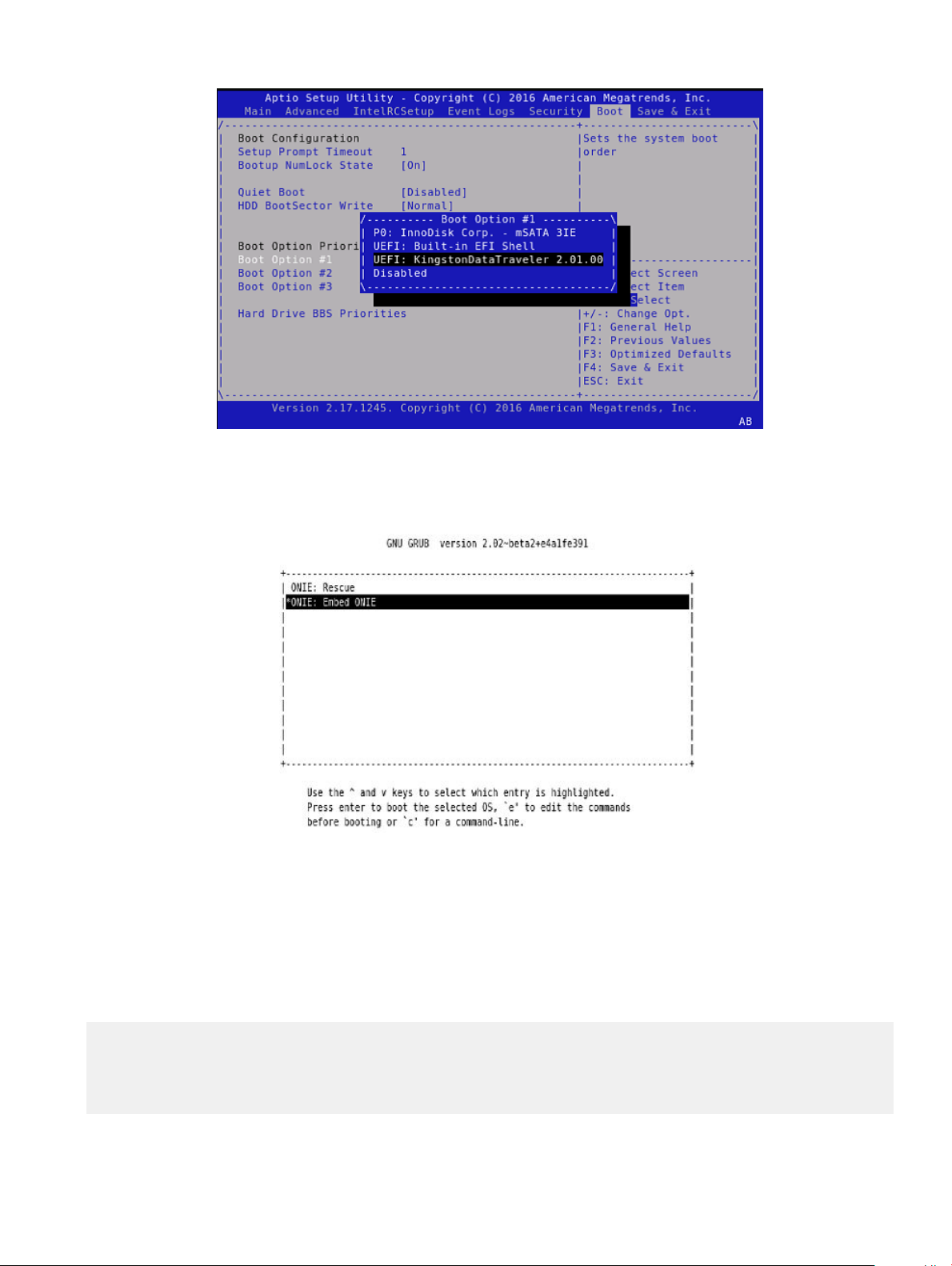
Figure 2. Setup utility
After the system exits the BIOS Boot menu, the system boots with the ONIE USB and presents the following menu:
Figure 3. Embed ONIE menu
10 Select the Embed ONIE option.
This step installs the UEFI ONIE version 3.26.1.1 on system. Any previous installation is removed.
Do not press any key during the Embed ONIE installation.
The following are the Embed ONIE logs:
ONIE: Embedding ONIE ...
Platform : x86_64-dell_<platform>_c2538-r0
Version : x.xx.x.x
Build Date: 2016-04-26T09:14-0700
[ 4.066378] dummy-irq: no IRQ given. Use irq=N
[ 14.296290] esas2r: driver will not be loaded because no ATTO esas2r devices were found
ONIE and Dell EMC OS installation instructions
12
Page 13

[ 14.463587] mtdoops: mtd device (mtddev=name/number) must be supplied
[ 16.328319] i8042: No controller found
[ 16.397853] fmc_write_eeprom fake-design-for-testing-f001: fmc_write_eeprom: no busid
passed, refusing all cards
[ 16.568122] intel_rapl: driver does not support CPU family 6 model 77
Info: Mounting kernel filesystems... done.
Info: Mounting ONIE-BOOT on /mnt/onie-boot ...
Info: Using eth0 MAC address: 4c:76:25:f4:7c:80
Info: eth0: Checking link... [ 18.571495] scsi 6:0:0:0: Direct-Access Kingston DataTraveler
2.0 1.00 PQ: 0 ANSI: 4
[ 18.707185] sd 6:0:0:0: Attached scsi generic sg1 type 0
[ 18.707703] sd 6:0:0:0: [sdb] 15148608 512-byte logical blocks: (7.75 GB/7.22 GiB)
[ 18.796392] sd 6:0:0:0: [sdb] Write Protect is off
[ 18.797033] sd 6:0:0:0: [sdb] Write cache: disabled, read cache: enabled, doesn't support
DPO or FUA
[ 19.159563] sd 6:0:0:0: [sdb] Attached SCSI removable disk
up.
Info: Trying DHCPv4 on interface: eth0
ONIE: Using DHCPv4 addr: eth0: 1[ 20.053045] random: dropbearkey urandom read with 94 bits
of entropy available
x.xx.xxx.xx / xxx.xxx.xxx.x
Starting: dropbear ssh daemon... done.
Starting: telnetd... done.
discover: ONIE embed mode detected. Running updater.
Starting: discover... done.
Please press Enter to activate this console. Info: eth0: Checking link... up.
Info: Trying DHCPv4 on interface: eth0
ONIE: Using DHCPv4 addr: eth0: x.xx.xxx.xx / xxx.xxx.xxx.x
ONIE: Starting ONIE Service Discovery
Info: Found static url: file:///lib/onie/onie-updater
[ 29.744855] random: nonblocking pool is initialized
ONIE: Executing installer: file:///lib/onie/onie-updater
Verifying image checksum ... OK.
Preparing image archive ... OK.
ONIE: Version : x.xx.x.x
ONIE: Architecture : x86_64
ONIE: Machine : dell_<
ONIE: Machine Rev : 0
ONIE: Config Version: 1
Installing ONIE on: /dev/sda
/proc/devices: No entry for device-mapper found
/proc/devices: No entry for device-mapper found
ONIE: Success: Firmware update URL: file:///lib/onie/onie-updater
ONIE: Success: Firmware update version: x.xx.x.x
ONIE: Rebooting...
discover: ONIE embed mode detected.
Stopping: discover...start-stop-daemon: warning: killing process 1441: No such process
Stopping: dropbear ssh daemon... done.
Stopping: telnetd... done.
platform>_c2538
Stopping: syslogd... done.
Info: Unmounting kernel filesystems
The system is going down NOW!
Sent SIGTERM to all processes
Sent SIGKILL to all processes
Requesting system reboot
After the Embed-ONIE installation completes, the system bootups and presents the ONIE menu.
ONIE and Dell EMC OS installation instructions
13
Page 14
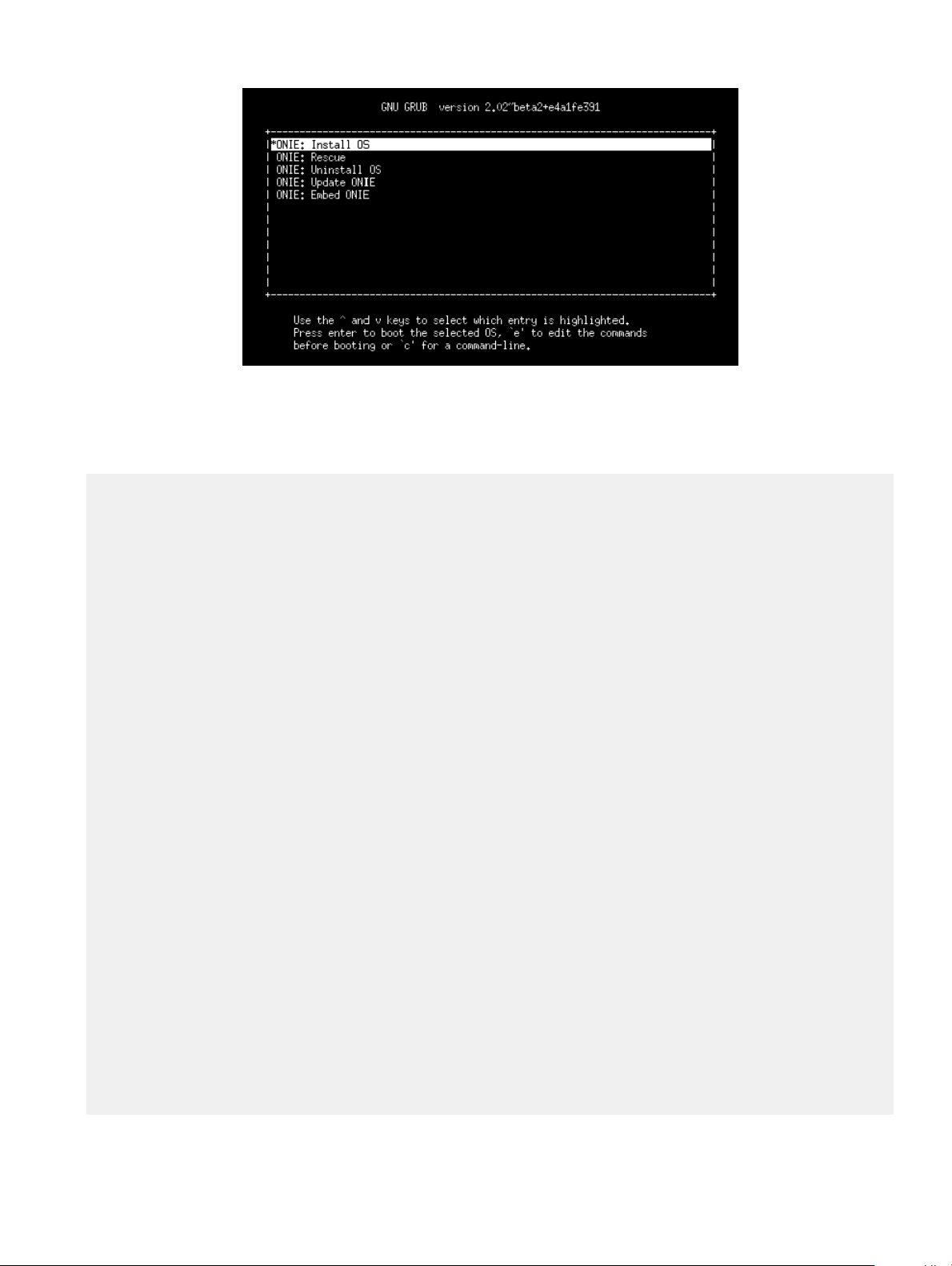
Figure 4. ONIE install menu
The system comes up in ONIE Install mode by default, as shown:
ONIE: OS Install Mode ...
Version : x.xx.x.x
Build Date: 2016-04-26T09:14-0700
ONIE: OS Install Mode ...
Version : x.xx.x.x
Build Date: 2016-04-26T09:14-0700
[ 4.759116] dummy-irq: no IRQ given. Use irq=N
[ 4.835970] esas2r: driver will not be loaded because no ATTO esas2r
devices were found
[ 5.003050] mtdoops: mtd device (mtddev=name/number) must be supplied
[ 6.867708] i8042: No controller found
[ 6.937375] fmc_write_eeprom fake-design-for-testing-f001:
fmc_write_eeprom: no busid passed, refusing all cards
[ 7.107669] intel_rapl: driver does not support CPU family 6 model 77
Info: Mounting kernel filesystems... done.
Info: Mounting ONIE-BOOT on /mnt/onie-boot ...
[ 8.018377] random: fsck urandom read with 73 bits of entropy available
Info: Mounting EFI System on /boot/efi ...
Info: Using eth0 MAC address: 4c:76:25:f4:7c:80
Info: eth0: Checking link... [ 8.902787] scsi 6:0:0:0: Direct-Access
Kingston DataTraveler 2.0 1.00 PQ: 0 ANSI: 4
[ 9.038475] sd 6:0:0:0: Attached scsi generic sg1 type 0
[ 9.038993] sd 6:0:0:0: [sdb] 15148608 512-byte logical blocks: (7.75
GB/7.22 GiB)
[ 9.253877] sd 6:0:0:0: [sdb] Write Protect is off
[ 9.254546] sd 6:0:0:0: [sdb] Write cache: disabled, read cache: enabled,
doesn't support DPO or FUA
[ 9.492124] sd 6:0:0:0: [sdb] Attached SCSI removable disk
up.
Info: Trying DHCPv4 on interface: eth0
ONIE: Using DHCPv4 addr: eth0: x.xx.xxx.xx / xxx.xxx.xxx.x
Starting: dropbear ssh daemon... done.
Starting: telnetd... done.
[ 11.789298] random: nonblocking pool is initialized
discover: installer mode detected. Running installer.
Starting: discover... done.
Please press Enter to activate this console. Info: eth0: Checking link... up.
Info: Trying DHCPv4 on interface: eth0
ONIE: Using DHCPv4 addr: eth0: x.xx.xxx.xx / xxx.xxx.xxx.x
ONIE: Starting ONIE Service Discovery
Info: Fetching
ONIE and Dell EMC OS installation instructions
14
Page 15

http://xx.xx.xxx.x/onie-installer-x86_64-dell_<platform>_c2538-r0 ...
Info: Fetching http://xx.xx.xxx.x/onie-installer-x86_64-dell_<platform>_c2538
...
Info: Fetching http://xx.xx.xxx.x/onie-installer-dell_<platform>_c2538 ...
Info: Fetching http://xx.xx.xxx.x/onie-installer-x86_64 ...
Info: Fetching http://xx.xx.xxx.x/onie-installer ...
Info: Fetching
http://xx.xx.xxx.x/onie-installer-x86_64-dell_<
Info: Fetching http://xx.xx.xxx.x/onie-installer-x86_64-dell_<platform>_c2538
...
11 Stop ONIE Discovery mode.
ONIE:/ # onie-discovery-stop
The operation has completed successfully.
ONIE:/ #
12 Verify the ONIE Linux kernel version and partition layout.
This step veries that you are running the correct kernel in ONIE as the kernel is separate from the ONIE environment.
ONIE:/ # uname -a
Linux onie 4.1.28-onie+ #1 SMP Wed Sep 7 14:38:43 PDT 2016 x86_64 GNU/Linux
ONIE:/ # sgdisk -p /dev/sda
Disk /dev/sda: 31277232 sectors, 14.9 GiB
Logical sector size: 512 bytes
Disk identifier (GUID): 763E53FF-B894-40FD-B0F9-FBAE2ED4B0B5
Partition table holds up to 128 entries
First usable sector is 34, last usable sector is 31277198
Partitions will be aligned on 2048-sector boundaries
Total free space is 30490733 sectors (14.5 GiB)
Number Start (sector) End (sector) Size Code Name
1 2048 526335 256.0 MiB EF00 EFI System
2 526336 788479 128.0 MiB 3000 ONIE-BOOT
ONIE:/ #
13 Verify that efibootmgr runs and displays the valid boot options.
ONIE:/ # efibootmgr
BootCurrent: 0000
Timeout: 1 seconds
BootOrder: 0000,0006,0001,0003
Boot0000* ONIE: Open Network Install Environment
Boot0001* Hard Drive
Boot0003* UEFI: Built-in EFI Shell
Boot0006* UEFI: KingstonDataTraveler 2.01.00 14
platform>_c2538-r0 ...
ONIE and Dell EMC OS installation instructions
15
Page 16

3
ONIE overview
This chapter describes system diagnostics and troubleshooting. After running the diagnostic tools, your system displays pass or fail test
results. If all tests pass, the diagnostic tools exit normally. If a test fails, each diagnostic tool oers a dierent result.
NOTE: The troubleshooting package includes a README le that lists the tools version and the overall troubleshooting package
version. For more information, see this README le.
NOTE: To download the Release Notes, go to www.dell.com/support.
This system uses the power-on self test (POST) diagnostic tool that automatically runs during the system power-on at the BIOS level. This
tool tests for catastrophic hardware failures that prevent booting the system. The error code is saved in CMOS for the next boot. There is
no physical alarm indication.
ONIE expansion
To view all the ONIE commands available, from the ONIE prompt, enter onie- and click <tab> twice.
ONIE:/ # onie- <TAB><TAB>
onie-boot-mode onie-fwpkg onie-syseeprom
onie-console onie-nos-install onie-sysinfo
onie-discovery-start onie-self-update onie-uninstaller
onie-discovery-stop onie-support
Topics:
• Boot processes
• View system information
Boot processes
After the BIOS, POST runs to verify the devices required to boot to ONIE GRUB.
POST
POST diagnostics verify the system DRAM, DIMM, SPD, memory, RTC/NVRAM, and PCI devices. Test conguration parameters and test
results are saved in NVRAM.
Capture support data from ONIE
1 Capture support data to the screen.
ONIE:/ # dmesg
2 Capture support data to the onie-support.tar.bz2 gzip le.
ONIE-support creates the support le. To store the le, enter the location; for example, ONIE:/# onie-support/tmp.
ONIE:/ # onie-support <output_directory>
16 ONIE overview
Page 17

The ONIE support le includes the following:
• kernel_cmdline
• runtime-export-env
• runtime-process
• runtime-set-env
• log/messages
• log/onie.log
Output example
Success: Support tarball created: /tmp/onie-support.tar.bz2
Change default grub boot entry
To view or set the default Boot mode, the onie-boot-mode command has two options —l, the default, and —o. The Grub boot default
shows the current default entry.
View or set the default Grub boot entry.
ONIE:/ # onie-boot-mode [-o <onie_mode>]
The -o command options include:
• install—ONIE OS Installer mode
• rescue—ONIE Rescue mode
• uninstall—ONIE OS Uninstall mode
• update—ONIE Self-Update mode
• embed—ONIE Self-Update mode and Embed ONIE
• none—Uses System Default Boot mode. This mode uses the rst ONIE boot menu entry.
The -l command option lists the current default entry—this is the default setting.
View system information
To view your system information; for example, the model, part number, serial number, and service tag, use the following commands:
1 Boot into ONIE.
2 Enter the onie-syseeprom command.
ONIE:/ # onie-syseeprom
TlvInfo Header:
Id String: TlvInfo
Version: 1
Total Length: 162
TLV Name Code Len Value
-------------------- ---- --- ----Part Number 0x22 6 0W1K08
Serial Number 0x23 20 CN0W1K08779316470002
Product Name 0x21 8 <
Device Version 0x26 1 0
Label Revision 0x27 3 X00
Manufacture Date 0x25 19 04/08/2016 08:43:05
Manufacturer 0x2B 5 77931
Country Code 0x2C 2 CN
Vendor Extension 0xFD 1 0x00
MAC Addresses 0x2A 2 256
platform>
ONIE overview
17
Page 18

Service Tag 0x2F 7 2WCSG02
Vendor Name 0x2D 4 DELL
Diag Version 0x2E 6 01_010
Base MAC Address 0x24 6 34:17:EB:05:B4:00
Platform Name 0x28 26 x86_64-dell_<platform>_c2538-r0
ONIE Version 0x29 8 x.xx.x.x
CRC-32 0xFE 4 0x99415608
Checksum is valid.
ONIE:/ #
Enter the onie-sysinfo –a command.
3
ONIE:/ # onie-sysinfo -a
CN0W1K08779316470002 0W1K08 34:17:EB:05:B4:00 3.28.1.2 674 dell_<platform>_c2538 0 x86_64dell_<platform>_c2538-r0 x86_64 1 gpt 2016-09-21T10:01-0700 bcm
ONIE:/ #
18 ONIE overview
Page 19

Dell EMC DIAG OS
These sections describe the Dell EMC diagnostics. These instructions apply to systems where ONIE diagnostics are not available.
Topics:
• Diagnostic package download
• View DIAG versions
• View CPLD versions
• Install or upgrade DIAG tools
• Restore factory defaults
Diagnostic package download
Load or update the DIAG-OS—the diag installer image—using the onie-nos-install command. The DIAG-OS installer runs in two
modes: Update mode or Install mode.
• In Update mode, the DIAG-OS updates the existing DIAG-OS and boots back to ONIE.
• In Install mode, the DIAG-OS erases the existing DIAG-OS and loads the new DIAG-OS.
4
: If you have a recovery USB plugged into your system, remove it before installing the DIAG-OS using the onie-nos-
NOTE
install command.
NOTE: Before you begin, go to www.dell.com/support and download the diagnostic package.
1 Enter the onie-discovery-stop command to stop ONIE Discovery mode.
2 Assign an IP address to the management interface and verify the network connectivity.
ONIE:/ # ifconfig eth0 xx.xx.xx.xx netmask xxx.xxx.x.x up
ONIE:/ # ifconfig
eth0 Link encap:Ethernet HWaddr 34:17:EB:05:B4:00
inet addr:xx.xx.xx.xx Bcast:xx.xx.xxx.xxx Mask:xxx.xxx.x.x
inet6 addr: fe80::3617:ebff:fe05:b400/64 Scope:Link
UP BROADCAST RUNNING MULTICAST MTU:1500 Metric:1
RX packets:43 errors:0 dropped:0 overruns:0 frame:0
TX packets:31 errors:0 dropped:0 overruns:0 carrier:0
collisions:0 txqueuelen:1000
RX bytes:5118 (4.9 KiB) TX bytes:7104 (6.9 KiB)
Memory:dff40000-dff5ffff
3 Upgrade the DIAG Installer.
Again, boot to ONIE Rescue mode and install the onie diag installer.
: In Install mode, the DIAG-OS installation removes any existing NOS and DIAG-OS partition. If you do not create
NOTE
file /tmp/diag_os_install_mode, the DIAG-OS installs in Upgrade mode. In this case, the installation process does
NOT touch any existing NOS.
ONIE:/ onie-nos-install tftp://<tftp-server ip>/<filepath>/filename/diag-install
er-x86_64-dell_<platform>_c2538-r0-2016-08-12.bin
discover: installer mode detected.
Stopping: discover... done.
Info: Fetching tftp://<tftp-server ip>/users/<
user>/<platform>/diag-installer-x86_64-
Dell EMC DIAG OS 19
Page 20

dell_<platform>_c2538-r0-2016-08-12.bin ...
users/<user>/<platform> 100% |*******************************| 154M 0:00:00 ETA
ONIE: Executing installer: tftp://<tftp-server ip>/users/<user>/<platform>/diag-installerx86_64-dell_<platform>_c2538-r0-2016-08-12.bin
Ignoring Verifying image checksum ... OK.
cur_dir / archive_path /var/tmp/installer tmp_dir /tmp/tmp.qlnVIY
Preparing image archive ...sed -e '1,/^exit_marker$/d' /var/tmp/installer | tar xf - OK.
Diag-OS Installer: platform: x86_64-dell_<
EDA-DIAG Partiton not found.
Diag OS Installer Mode : INSTALL
Creating new diag-os partition /dev/sda3 ...
Warning: The kernel is still using the old partition table.
The new table will be used at the next reboot.
The operation has completed successfully.
EDA-DIAG dev is /dev/sda3
mke2fs 1.42.13 (17-May-2015)
Creating filesystem with 262144 4k blocks and 65536 inodes
Filesystem UUID: 63fc156f-b6c1-415d-9676-ae4478704c5a
Superblock backups stored on blocks:
32768, 98304, 163840, 229376
Allocating group tables: done
Writing inode tables: done
Creating journal (8192 blocks): done
Writing superblocks and filesystem accounting information: done
Created filesystem on /dev/sda3 with label EDA-DIAG
platform>_c2538-r0
Mounted /dev/sda3 on /tmp/tmp.BBEygm
Preparing /dev/sda3 EDA-DIAG for rootfs install
untaring into /tmp/tmp.BBEygm
rootfs copy done
Success: Support tarball created: /tmp/tmp.BBEygm/onie-support.tar.bz2
Updating Grub Cfg /dev/sda3 EDA-DIAG
ONIE uefi_uuid 69AD-9CBF
INSTALLER DONE...
Removing /tmp/tmp.qlnVIY
ONIE: NOS install successful: tftp://<tftp-server ip>/users/<
x86_64-dell_<platform>_c2538-r0-2016-08-12.bin
ONIE: Rebooting...
ONIE:/ # discover: installer mode detected.
Stopping: discover...start-stop-daemon: warning: killing process 2605: No such process
done.
Stopping: dropbear ssh daemon... done.
Stopping: telnetd... done.
Stopping: syslogd... done.
Info: Unmounting kernel filesystems
umount: can't umount /: Invalid argument
The system is going down NOW!
Sent SIGTERM to all processes
Sent SIGKILL tosd 4:0:0:0: [sda] Synchronizing SCSI cache
reboot: Restarting system
reboot: machine restart
user>/<platform>/diag-installer-
BIOS Boot Selector for <
Primary BIOS Version x.xx.x.x_MRC48
Dell EMC DIAG OS
20
platform>
Page 21

SMF Version: MSS 1.3.1, FPGA 0.3
Last POR=0x11, Reset Cause=0x55
POST Configuration
CPU Signature 406D8
CPU FamilyID=6, Model=4D, SteppingId=8, Processor=0
Microcode Revision 125
Platform ID: 0x10041A43
PMG_CST_CFG_CTL: 0x40006
BBL_CR_CTL3: 0x7E2801FF
Misc EN: 0x840081
Gen PM Con1: 0x203808
Therm Status: 0x884C0000
POST Control=0xEA000100, Status=0xE6000000
BIOS initializations...
CPGC Memtest ................................ PASS
CPGC Memtest ................................ PASS
Booting `EDA-DIAG'
Loading DIAG-OS ...
[ 3.786758] dummy-irq: no IRQ given. Use irq=N
[ 3.792812] esas2r: driver will not be loaded because no ATTO esas2r devices were found
[ 3.818171] mtdoops: mtd device (mtddev=name/number) must be supplied
[ 4.880285] i8042: No controller found
[ 4.890134] fmc_write_eeprom fake-design-for-testing-f001: fmc_write_eeprom: no busid
passed, refusing all cards
[ 4.901699] intel_rapl: driver does not support CPU family 6 model 77
Debian GNU/Linux 8 dell-diag-os ttyS1
dell-diag-os login: root
Password:
Linux dell-diag-os 3.15.10 #1 SMP Fri Aug 12 05:14:52 PDT 2016 x86_64
The programs included with the Debian GNU/Linux system are free software;
the exact distribution terms for each program are described in the
individual files in /usr/share/doc/*/copyright.
Debian GNU/Linux comes with ABSOLUTELY NO WARRANTY, to the extent
permitted by applicable law.
Diag OS version <
Build date/time Fri Aug 12 05:23:56 PDT 2016
Build server netlogin-eqx-03
Build by <name>
Kernel Info:
Linux 3.15.10 #1 SMP Fri Aug 12 05:14:52 PDT 2016 x86_64 GNU/Linux
Debian GNU/Linux 8 \n \l
Done Initializing Ethernet
root@dell-diag-os:~#
root@dell-diag-os:~#
root@dell-diag-os:~#
root@dell-diag-os:~#
root@dell-diag-os:~#
root@dell-diag-os:~#
4 Start diagnostics.
To start the ONIE diagnostics, use the DIAG-OS option from the GRUB menu.
platform>_DIAG_OS_x.xx.x.x
Dell EMC DIAG OS
21
Page 22

a Boot into the DIAG OS.
b Log in as root.
Password: calvin.
c Install the EDA-DIAG tools package.
d Run /opt/dellemc/diag/bin/edatool.
NOTE: To return to your networking operating software, enter the reboot command.
Diagnostic test suite
After the system boots up, select the EDA-DIAG option to run the diagnostic test suite.
To select which entry is highlighted, use the up and down arrow keys. Press Enter to select an operating software-selected OS or enter e
to edit the commands before booting. Enter c for a command line. The highlighted entry, displaying *, executes automatically in the
operating system.
GNU GRUB version 2.02~beta2+e4a1fe391
+---------------------------+
|ONIE: Install OS |
|ONIE: Rescue |
|ONIE: Uninstall OS |
|ONIE: Update ONIE |
|ONIE: Embed ONIE |
|*EDA-DIAG |
| |
| |
| |
+---------------------------+
View DIAG versions
To display the DIAG version installed in the DIAG OS, use the dpkg -l | grep dn-diags command at the root@dell-diag-os:~
prompt.
root@dellemc-diag-os:~# dpkg -l | grep dn-diags
ii dn-diags-<platform>-on.deb 3.xx.4.1-x amd64 Dell Networking Diagnostics
View CPLD versions
To view CPLD data, including the fan status, PSU status, current programmed version, and image packed version, use the
cpldupgradetool or updatetool command at the prompt.
• For the cpldupgradetool command:
root@dell-diag-os:/# cpldupgradetool --cpldver
CPLD1 Version 0x00
CPLD2 Version 0x01
CPLD3 Version 0x01
CPLD4 Version 0x01
root@dell-diag-os:/#
• For the updatetool command:
root@dellemc-diag-od~#updatetool --device_version --dev=CPU_CPLD
CPU_CPLD version:
System CPLD Version : offset 0x00 = 0xc
7: 4 Major Revision = 0
3: 0 Minor Revision = c
Scratch Register : offset 0x01 = 0x0
Dell EMC DIAG OS
22
Page 23

Install or upgrade DIAG tools
To install or upgrade the DIAGs in the DIAGs OS, use the dpkg --install dn-diags-<platform>-DiagOS-<version>-
<date>.deb command.
root@dell-diag-os:~#dpkg --install dn-diags-<platform>-DiagOS-<version>-<date>.de
Selecting previously unselected package dn-diags-<platform>.deb.
(Reading database ... 18873 files and directories currently installed.)
Preparing to unpack dn-diags-<
Unpacking dn-diags-<platform>.deb (1.10) ...
Setting up dn-diags-<
root@dell-diag-os:~#
platform>.deb (1.10) ...
platform>-DiagOS-<version>-<date>.deb ...
Restore factory defaults
To restore your system factory defaults, reboot the system to ONIE: Uninstall OS mode.
If it is not possible to restore your factory defaults with the installed OS, reboot the system from the Grub menu and select ONIE:
Rescue. ONIE Rescue bypasses the installed OS and boots the system into ONIE until you reboot the system. After ONIE Rescue
completes, the system resets and boots to the ONIE console.
CAUTION: Restoring factory defaults erases any installed OS and requires a long time to erase storage.
1 Restore the factory defaults on your system from the Grub menu using the ONIE: Uninstall OS command.
To select which entry is highlighted, use the up and down arrow keys.
GNU GRUB version 2.02~beta2+e4a1fe391
+---------------------------------+
| ONIE: Install OS |
| ONIE: Rescue |
|*ONIE: Uninstall OS |
| ONIE: Update ONIE |
| ONIE: Embed ONIE |
| EDA-DIAG |
| |
| |
| |
+---------------------------------+
2 Press ENTER to activate the console.
3 Return to the default ONIE settings using the onie-uninstaller command.
ONIE:/ # onie-uninstaller
Erasing internal mass storage device: /dev/sda4 (32MB)
Percent complete: 100%
Erase complete.
Deleting partition 4 from /dev/sda
Erasing internal mass storage device: /dev/sda5 (300MB)
Percent complete: 100%
Erase complete.
Deleting partition 5 from /dev/sda
Erasing internal mass storage device: /dev/sda6 (300MB)
Percent complete: 100%
Erase complete.
Deleting partition 6 from /dev/sda
Erasing internal mass storage device: /dev/sda7 (12461MB)
Percent complete: 100%
Erase complete.
Deleting partition 7 from /dev/sda
Installing for i386-pc platform.
Installation finished. No error reported.
Uninstall complete. Rebooting...
Dell EMC DIAG OS
23
Page 24

ONIE:/ # discover: Rescue mode detected. No discover stopped.
Stopping: dropbear ssh daemon... done.
Stopping: telnetd... done.
Stopping: syslogd... done.
Info: Unmounting kernel filesystems
The system is going down NOW!
Sent SIGTERM to all processes
Sent SIGKILL tosd 4:0:0:0: [sda] Synchronizing SCSI cache
Restarting system.
machine restart
24 Dell EMC DIAG OS
Page 25

5
Dell EMC DAIG-OS tools
This section describes how to use the Dell EMC diagnostics operating system (DIAG-OS). The DIAG-OS provides a suite of tools to help
diagnose issues seen on the system, or to run a health check to ensure that the hardware is operating properly.
Diagnostic tools
The DIAG-OS uses standard Linux drivers and contains the following tools you can use to evaluate the health of your system. The tools are
packaged for both the DIAG-OS, which is a simple OS of the same kernel version, and small rootfs to support the tools and drivers.
NOTE: By default, the system’s I/O modules are down. Power up the I/O modules or the Opticstool and NPUtool reports failures.
For information about how to power up the I/O modules, see the
support.
Topics:
• edatool
• cpldupgradetool
• cputool
• eepromtool
• ethtool
• fantool
• ashrom
• gpiotool
• i2ctool
• ledtool
• lpctool
• memtool
• nputool
• nvramtool
• opticstool
• pcitool
• phytool
• pltool
• psutool
• rtctool
• smartctl
• smarttool
• smbiostool
• storagetool
• temptool
• updatetool
• vmetool
Dell EMC Installation Guide
for your system at www.dell.com/
Dell EMC DAIG-OS tools 25
Page 26

• Diagnostic package
edatool
The diagnostics tools include edatool. To test the basic functionality of the system, use the edatool.
The edatool executes a script of simple commands, similar to commands in the CLI. Usually, the diagnostics tools run these types of
tests. The success or failure of these tools is reported. At the end of the edatool run, reports the PASSED or FAILED results in a
standard format the test scripts can easily parse.
Tests
The edatool does not have a test command, but instead runs all the tests that are scripted.
CLI options
DellEmc Diag - Extended Diagnostics Application
version 1.4, x.xx.x.x-x
build, 2017/05/23,
Syntax: edatool <option>
Show the Help-text:=
edatool --h (or)
edatool -h
Lists tests in config files:=
edatool --list (or)
edatool -l
Config file to use for tests:=
edatool --config=<config_file> (or)
edatool -f <config_file>
Config file to use for extended tests:=
edatool --extended-config=<config_file> (or)
edatool -X <config_file>
Display test list or test result or modify test item status:=
edatool --testlist=show/result/<on/off,<test_id>,<test_id>...>(or)
edatool -L show/result/<on/off,<test_id>,<test_id>...>
Run all or selected test item in test list:=
edatool --testrun=all/<test_id> (or)
edatool --R all/<test_id>
Execute repeatedly command by count:=
edatool --iteration=max/<count> [option1] [option2]... (or)
edatool -I max/<count> [option1] [option2]...
Usage:=
-h, --h Show the help text
-l, --list List the understood TLV codes and names
-I, --iteration= Iteration command execution
-L, --testlist= Test list status
-R, --testrun= Run test item
-f, --config= To specify the location of the config file e.g. /etc/dn/diag/
<file_name>
-X, --extended-config= Config file to use for extended tests
Output
root@dell-diag-os:~# edatool
*****************************
* Diagnostics Application *
*****************************
Dell-EMC Diag edatool version 1.4, package x.xx.x.x 2016/11/21
Dell EMC DAIG-OS tools
26
Page 27

Dell-EMC Diag cputool - version 1.1 package x.xx.x.x 2016/11/21
Dell-EMC Diag fantool - version 1.5 package x.xx.x.x 2016/11/21
Dell-EMC Diag gpiotool - version 1.4 package x.xx.x.x 2016/11/21
Dell-EMC Diag i2ctool - version 1.5 package x.xx.x.x 2016/11/21
Dell-EMC Diag ledtool - version 1.0 package x.xx.x.x 2016/11/21
Dell-EMC Diag lpctool - version 1.0 package x.xx.x.x 2016/11/21
Dell-EMC Diag memtool - version 1.5 package x.xx.x.x 2016/11/21
Dell-EMC Diag nputool - version 1.0 sdk-6.5.5 package x.xx.x.x 2016/11/21
Dell-EMC Diag nvramtool - version 1.5 package x.xx.x.x 2016/11/21
Dell-EMC Diag opticstool - version 1.0 package x.xx.x.x 2016/11/21
Dell-EMC Diag pcitool - version 1.5 package x.xx.x.x 2016/11/21
Dell-EMC Diag pltool - version 1.5 package x.xx.x.x 2016/11/21
Dell-EMC Diag psutool - version 1.4 package x.xx.x.x 2016/11/21
Dell-EMC Diag rtctool - version 1.1 package x.xx.x.x 2016/11/21
Dell-EMC Diag smbiostool - version 1.2 package x.xx.x.x 2016/11/21
Dell-EMC Diag storagetool - version 1.1 package x.xx.x.x 2016/11/21
Dell-EMC Diag temptool - version 1.4 package x.xx.x.x 2016/11/21
Testing PCI devices:
+ Checking PCI 00:00.0, ID=1f0c8086 ....................... Passed
+ Checking PCI 00:01.0, ID=1f108086 ....................... Passed
+ Checking PCI 00:02.0, ID=1f118086 ....................... Passed
+ Checking PCI 00:03.0, ID=1f128086 ....................... Passed
+ Checking PCI 00:0e.0, ID=1f148086 ....................... Passed
+ Checking PCI 00:0f.0, ID=1f168086 ....................... Passed
+ Checking PCI 00:13.0, ID=1f158086 ....................... Passed
+ Checking PCI 00:14.0, ID=1f418086 ....................... Passed
+ Checking PCI 00:14.1, ID=1f418086 ....................... Passed
+ Checking PCI 00:14.2, ID=1f418086 ....................... Passed
+ Checking PCI 00:16.0, ID=1f2c8086 ....................... Passed
+ Checking PCI 00:17.0, ID=1f228086 ....................... Passed
+ Checking PCI 00:18.0, ID=1f328086 ....................... Passed
+ Checking PCI 00:1f.0, ID=1f388086 ....................... Passed
+ Checking PCI 00:1f.3, ID=1f3c8086 ....................... Passed
+ Checking PCI 01:00.0, ID=837514e4 ....................... Passed
+ Checking PCI 01:00.1, ID=837514e4 ....................... Passed
PCI devices: Overall test results --------------------- >>> Passed
Testing I2C devices:
Checking I2C devices on bus 0:
+ Checking Clock GEN 0x69 ..... Passed
+ Checking SPD0 0x50 ..... Passed
Checking I2C devices on bus 1:
+ Checking CPU Board I2C Mux 0x70 ..... Passed
+ Checking CPU Board EEPROM1 0x53 ..... Passed
+ Checking CPU Board EEPROM2 0x57 ..... Passed
+ Checking Switch Brd EEPROM 0x50 ..... Passed
+ Checking CPLD2 0x3e ..... Passed
+ Checking CPLD3 0x3e ..... Passed
+ Checking CPLD4 0x3e ..... Passed
+ Checking SFP+ 1 0x50 ..... Passed
+ Checking SFP+ 2 0x50 ..... Passed
+ Checking SFP+ 3 0x50 ..... Passed
+ Checking SFP+ 4 0x50 ..... Passed
Dell EMC DAIG-OS tools
27
Page 28

+ Checking SFP+ 5 0x50 ..... Passed
+ Checking SFP+ 6 0x50 ..... Passed
+ Checking SFP+ 7 0x50 ..... Passed
+ Checking SFP+ 8 0x50 ..... Passed
+ Checking SFP+ 9 0x50 ..... Passed
+ Checking SFP+ 10 0x50 ..... Passed
+ Checking SFP+ 11 0x50 ..... Passed
+ Checking SFP+ 12 0x50 ..... Passed
+ Checking SFP+ 13 0x50 ..... Passed
+ Checking SFP+ 14 0x50 ..... Passed
+ Checking SFP+ 15 0x50 ..... Passed
+ Checking SFP+ 16 0x50 ..... Passed
+ Checking SFP+ 17 0x50 ..... Passed
+ Checking SFP+ 18 0x50 ..... Passed
+ Checking SFP+ 19 0x50 ..... Passed
+ Checking SFP+ 20 0x50 ..... Passed
+ Checking SFP+ 21 0x50 ..... Passed
+ Checking SFP+ 22 0x50 ..... Passed
+ Checking SFP+ 23 0x50 ..... Passed
+ Checking SFP+ 24 0x50 ..... Passed
+ Checking SFP+ 25 0x50 ..... Passed
+ Checking SFP+ 26 0x50 ..... Passed
+ Checking SFP+ 27 0x50 ..... Passed
+ Checking SFP+ 28 0x50 ..... Passed
+ Checking SFP+ 29 0x50 ..... Passed
+ Checking SFP+ 30 0x50 ..... Passed
+ Checking SFP+ 31 0x50 ..... Passed
+ Checking SFP+ 32 0x50 ..... Passed
+ Checking SFP+ 33 0x50 ..... Passed
+ Checking SFP+ 34 0x50 ..... Passed
+ Checking SFP+ 35 0x50 .....
Verbose mode
Use the following steps to enable and set the verbose level.
Dell EMC DAIG-OS tools
28
Page 29

1 Set the Verbose level with a value of 0–3 using bits 4 and 5 of the EDA control reg (0x55).
For example, to set the verbose level to 2, set bit 5–1 (5=1) and bit 4–0 (4=0).
root@dellemc-diag-os:~# nvramtool --write --reg=0x55 --val=0x25
The value is written in hexadecimal. The xx10x1xx shows the bit positions of 2, 4&5, and bit 0 on the right.
2 Enable Verbose mode by setting bit 2 of the same reg to 1.
NOTE: If you disable Verbose mode, or bit 2 of reg 0x55 is set to 0, the default verbosity level is 0/zero.
EDA control reg (0x55):
• 5:4—EDA Verbose Level = 0/1/2/3 or verbosity level 0, 1, 2, or 3
• 3—EDA Extended Tests
• 2—EDA Verbose Mode = 0/1 (0=disabled; 1=enabled)
• 1—EDA stop on Error
• 0—EDA Enable
NOTE: If you do not need the Verbose mode settings to persist through reboots, you can use the environment variable method to
enable Verbose Mode.
export VERB_LEVEL=<setting 0,1,2 or 3>
To clear the environment variable, use the unset VERB_LEVEL command.
cpldupgradetool
The cpldupgradetool shows the CPLD version that is being used to upgrade the CPLD.
Tests
There are no dened tests with cpldupgradetool.
CLI options
root@dellemc-diag-os:~# cpldupgradetool
DellEmc Diag - CPLD Upgrade Tool
version 1.1, x.xx.x.x-x
build, 2017/05/23,
Syntax: cpldupgradetool <option>
Print the Help-Text:=
cpldupgradetool --h (or)
cpldupgradetool -h
Print the CPLD versions:=
cpldupgradetool --cpldver (or)
cpldupgradetool -c
Program a new CPLD image into CPLD's by specified index:=
cpldupgradetool --write [--index=-1] [--image=<file>] (or)
cpldupgradetool -w [-i -1] [-m <file>]
Usage:=
-h, --h Show the help text
-c, --cpldver CPLD version
-w, --write Write operation
-i, --index= Index
-m, --image= CPLD image
Dell EMC DAIG-OS tools
29
Page 30

Output
root@dell-diag-os:/# cpldupgradetool --h
Dell Diag - CPLD Upgrade Tool
version 1.1, x.xx.x.x
build, 2016/08/12,
Syntax: cpldupgradetool <option>
Print the Help-Text:=
cpldupgradetool --h (or)
cpldupgradetool -h
Print the CPLD versions:=
cpldupgradetool --cpldver (or)
cpldupgradetool -c
Program a new CPLD image into CPLD's by specified index:=
cpldupgradetool --write [--index=-1] [--image=<file>] (or)
cpldupgradetool -w [-i -1] [-m <file>]
Usage:=
-h, --h Show the help text
-c, --cpldver CPLD version
-w, --write Write operation
-i, --index= Index
-m, --image= CPLD image
root@dell-diag-os:/#
root@dell-diag-os:/# cpldupgradetool --cpldver
CPLD1 Version 0x00
CPLD2 Version 0x01
CPLD3 Version 0x01
CPLD4 Version 0x01
root@dell-diag-os:/#
root@dell-diag-os:cpldupgradetool--write --image=<platform>_cpld_v01.vme
Lattice Semiconductor Corp.
ispVME(tm) V12.2 Copyright 1998-2011.
For daisy chain programming of all in-system programmable devices
Invalid Format: CPLD_WE assertion level
TDI:39,TCK:35,TMS:36,WE:57,TRST:58,TDO:49,SelPin:0, Freq:2400
g_CoresiIspPins Init= 30000 g_SussiIspPins Init= 2000134 g_WEAssertLevel= 0
Processing virtual machine file (./<
CREATED BY: ispVM(R) System Version 18.0.1
CREATION DATE: 06/23/16 14:26:03
+=======+
| PASS! |
+=======+
platform>_cpld_v01.vme)......
cputool
The cputool displays the CPU information, reads and writes of the MSR and the LPC bus.
Tests
There are no dened tests with the cputool.
CLI options
root@dellemc-diag-os:~# cputool
DellEmc Diag - Cpu Tool
version 1.1, x.xx.x.x-x
Dell EMC DAIG-OS tools
30
Page 31

build, 2017/05/23,
Syntax: cputool <option>
Show the help-text:=
cputool --h (or)
cputool -h
Display the CPU info using CPU-ID:
cputool --cpuid[=--option] (or)
cputool -i [option]
Display the CPU info using x86info:=
cputool --x86info[=--option] (or)
cputool -x [option]
Read CPU register:=
cputool --readmsr --cpu=<cpuNumber> --reg=<regOffset> (or)
cputool -r -n <cpuNumber> -R <regOffset>
Write CPU register:=
cputool --writemsr --cpu=<cpuNumber> --reg=<regOffset> --val=<value> (or)
cputool -w <cpuNumber> -R <regOffset> -V <value>
Execute repeatedly command by count:=
cputool --iteration=max/<count> [option1] [option2]... (or)
cputool -I max/<count> [option1] [option2]...
Read the specified regiser in LPC bus:=
cputool --readlpc --reg=<reg> --size=<size> (or)
cputool -d -R <reg> -Z <size>
Write the specified regiser in LPC bus:=
cputool --writelpc --reg=<reg> --val=<value> --size=<size> (or)
cputool -W -R <reg> -V <value> -Z <size>
Usage:=
-h, --h Show the help text
-i, --cpuid CPU-Id
-x, --x86info x86 info
-r, --readmsr Read operation
-w, --writemsr Write operation
-n, --cpu= CPU
-R, --reg= Register
-V, --val= Value to be set
-Z, --size= Size
-I, --iteration= Iteration command execution
-d, --readlpc Read from LPC bus
-W, --writelpc Write to LPC bus
Output
root@dell-diag-os:/# cputool --h
Dell Diag - Cpu Tool
version 1.1, x.xx.x.x
build, 2016/08/12,
Syntax: cputool <option>
Show the help-text:=
cputool --h (or)
cputool -h
Display the CPU info using CPU-ID:
cputool --cpuid[=--option] (or)
cputool -i [option]
Display the CPU info using x86info:=
cputool --x86info[=--option] (or)
cputool -x [option]
Read CPU register:=
cputool --readmsr --cpu=<cpuNumber> --reg=<regOffset> (or)
cputool -r -n <cpuNumber> -R <regOffset>
Write CPU register:=
cputool --writemsr --cpu=<cpuNumber> --reg=<regOffset> --val=<value> (or)
cputool -w <cpuNumber> -R <regOffset> -V <value>
Read the specified regiser in LPC bus:=
cputool --readlpc --reg=<reg> --size=<size> (or)
cputool -d -R <reg> -Z <size>
Dell EMC DAIG-OS tools
31
Page 32

Write the specified regiser in LPC bus:=
cputool --writelpc --reg=<reg> --val=<value> --size=<size> (or)
cputool -W -R <reg> -V <value> -Z <size>
Usage:=
-h, --h Show the help text
-i, --cpuid CPU-Id
-x, --x86info x86 info
-r, --readmsr Read operation
-w, --writemsr Write operation
-n, --cpu= CPU
-R, --reg= Register
-V, --val= Value to be set
-Z, --size= Size
-d, --readlpc Read from LPC bus
-W, --writelpc Write to LPC bus
root@dell-diag-os:/#
root@dell-diag-os:/# cputool --x86info
x86info v1.30. Dave Jones 2001-2011
Feedback to <davej@redhat.com>.
Found 4 identical CPUs
Extended Family: 0 Extended Model: 4 Family: 6 Model: 77 Stepping: 8
Type: 0 (Original OEM)
CPU Model (x86info's best guess): Unknown model.
Processor name string (BIOS programmed): Intel(R) Atom(TM) CPU C2538 @ 2.40GHz
Total processor threads: 4
This system has 1 dual-core processor with hyper-threading (2 threads per core) running at an
estimated 2.40GHz
root@dell-diag-os:/#
eepromtool
To program the type, length, value (TLV) format EEPROMs, use the eepromtool. You can also use the eepromtool to show all the
TLV-formatted EEPROM contents or show specic EEPROM content by specifying the EEPROM type.
Tests
The test option in EEPROM devices allows you to verify the MAC address. Use this test for MAC address consistency.
CLI options
DellEmc Diag - Eeprom Tool
version 1.5, x.xx.x.x-x
build, 2017/05/23,
Syntax:= eepromtool <option>
Display help-text:=
eepromtool --help (or)
eepromtool -h
List the understood TLV codes and names:=
eepromtool --list (or)
eepromtool -l
List all eeprom devices:=
eepromtool --listdevices (or)
eepromtool -L
Dump the PSU eeprom:=
eepromtool --psueepromdump (or)
eepromtool -m
Dump the FAN eeprom:=
eepromtool --faneepromdump (or)
eepromtool -F
Show the EEPROM data:=
Dell EMC DAIG-OS tools
32
Page 33

eepromtool --eeprom=<eepromtype> --show (or)
eepromtool -P <eepromtype> -x
Reset the EEPROM data:=
eepromtool --eeprom=<eepromtype> --erase (or)
eepromtool -P <eepromtype> -e
Verify the MAC address in system-eeprom and mac-eeprom:=
eepromtool --eeprom=<eepromtype> --test (or)
eepromtool -P <eepromtype> -t
Look up a TLV by code and write the value to stdout:=
eepromtool --eeprom=<eepromtype> --get <code> (or)
eepromtool -P <eepromtype> -g <code>
Execute repeatedly command by count:=
eepromtool --iteration=max/<count> [option1] [option2]... (or)
eepromtool -I max/<count> [option1] [option2]...
Set a TLV code to a value:=
eepromtool --eeprom=<eepromtype> --set <code>=<value>,<code>=<value>...(or)
eepromtool -P <eepromtype> -s <code>=<value>,<code>=<value>...
Usage:=
-h, --h Show the help text
-l, --list List the understood TLV codes and names
-L, --listdevices List all EEPROM devices
-m, --psueepromdump Dump the PSU EEPROM
-F, --faneepromdump Dump the FAN EEPROM
-P, --eeprom= EEPROM type
-x, --show Show operation
-e, --erase Erase operation
-t, --test Test using the pre-programmed configuration or use supplied config
-I, --iteration= Iteration command execution
-g, --get Get operation
-s, --set Set operation
Output
root@dell-diag-os:/opt/dellemc/diag/bin# eepromtool --list
TLV Code TLV Name
======== =================
0x21 Product Name
0x22 Part Number
0x23 Serial Number
0x24 Base MAC Address
0x25 Manufacture Date
0x26 Device Version
0x27 Label Revision
0x28 Platform Name
0x29 Loader Version
0x2a MAC Addresses
0x2b Manufacturer
0x2c Country Code
0x2d Vendor Name
0x2e Diag Version
0x2f Service Tag
0xfd Vendor Extension
0xfe CRC-32
root@dell-diag-os:/opt/dellemc/diag/bin# eepromtool --listdevices
CPUEEPROM1
CPUEEPROM2
CPUEEPROM3
CPUEEPROM4
CPUEEPROM5
CPUEEPROM6
CPUEEPROM7
CPUEEPROM8
FAN1EEPROM
FAN2EEPROM
FAN3EEPROM
FAN4EEPROM
Dell EMC DAIG-OS tools
33
Page 34

FAN5EEPROM
SwitchEEPROM
root@dell-diag-os:/# eepromtool --psueepromdump
************PSU1_CountryCode*************
Registers 0x24a - 0x24b
CN
************PSU1_DellPartNumber*************
Registers 0x24c - 0x251
02RPHX
************PSU1_MfgID*************
Registers 0x252 - 0x256
17972
************PSU1_MfgDate*************
Registers 0x257 - 0x25e
151117
************PSU1_SerialNo*************
Registers 0x25f - 0x262
01CG
************PSU1_ServiceTag*************
Registers 0x263 - 0x269
************PSU1_LabelRevision*************
Registers 0x26a - 0x26c
A00
************PSU2_CountryCode*************
Registers 0x283 - 0x284
CN
************PSU2_DellPartNumber*************
Registers 0x285 - 0x28a
02RPHX
************PSU2_MfgID*************
Registers 0x28b - 0x28f
17972
************PSU2_MfgDate*************
Registers 0x290 - 0x297
151117
************PSU2_SerialNo*************
Registers 0x298 - 0x29b
015F
************PSU2_ServiceTag*************
Registers 0x29c - 0x2a2
************PSU2_LabelRevision*************
Registers 0x2a3 - 0x2a5
A00
root@dell-diag-os:/#
root@dell-diag-os:/opt/dellemc/diag/bin#
root@dell-diag-os:/opt/dellemc/diag/bin# eepromtool --eeprom=cpueeprom2 --set 0x21='cpu2'
Notice: Invalid TLV checksum found. Using default contents.
Adding TLV 0x21: Product Name
Programming passed.
TlvInfo Header:
Id String: TlvInfo
Version: 1
Total Length: 12
TLV Name Code Len Value
-------------------- ---- --- -----
Product Name 0x21 4 cpu2
CRC-32 0xFE 4 0x338B2B86
Checksum is valid.
root@dell-diag-os:/opt/dellemc/diag/bin#
root@dell-diag-os:/opt/dellemc/diag/bin# eepromtool --eeprom=cpueeprom2 --get 0x21
cpu2
root@dell-diag-os:/opt/dellemc/diag/bin#
root@dell-diag-os:/opt/dellemc/diag/bin# eepromtool --eeprom=cpueeprom2 --show
TlvInfo Header:
Id String: TlvInfo
Version: 1
Total Length: 12
TLV Name Code Len Value
Dell EMC DAIG-OS tools
34
Page 35

-------------------- ---- --- -----
Product Name 0x21 4 cpu2
CRC-32 0xFE 4 0x338B2B86
Checksum is valid.
root@dell-diag-os:/opt/dellemc/diag/bin#
root@dell-diag-os:/opt/dellemc/diag/bin# eepromtool --eeprom=cpueeprom1 --erase
Programming passed.
EEPROM does not contain data in a valid TlvInfo format.
root@dell-diag-os:/opt/dellemc/diag/bin# eepromtool --eeprom=cpueeprom1 --show
Notice: Invalid TLV header found. Using default contents.
Notice: Invalid TLV checksum found. Using default contents.
TlvInfo Header:
Id String: TlvInfo
Version: 1
Total Length: 6
TLV Name Code Len Value
-------------------- ---- --- -----
CRC-32 0xFE 4 0xD4431C18
Checksum is valid.
root@dell-diag-os:/opt/dellemc/diag/bin#
ethtool
The ethtool provides management interface details.
fantool
The fantool tests the fans in the system, sets, and reports the fan speeds and the fan tray eld replaceable unit (FRU) registers. The
fantool also reports the airow direction of the fans. The psutool command controls the PSU fans.
Tests
The fantool tests the fans by setting them to dierent speeds and then verifying the congured fan speeds.
Registers and values pass as hexadecimal values with or without the preceding 0x. Fans display from 1 to Max System Fans.
CLI options
DellEmc Diag - Fan Controller Tool
version 1.5, x.xx.x.x-x
build, 2017/05/23
Syntax: fantool <option>
Show the help-text:=
fantool --h (or)
fantool -h
Initialize the fans to the default state:=
fantool --init (or)
fantool -i
Test using the Fan Controller config file:=
fantool --test [--fan=<fan>] [--lpc] (or)
fantool -t [-F <fan>] [-l]
Get the speed of the specified fan or all fans in RPM:=
fantool --get --fan=<fan | all> [--lpc] (or)
fantool -g -F <fan | all> [-l]
Set the fan(s) to the speed:=
fantool --set --fan=<fan | all> --speed=<speed in RPM> (or)
fantool -s -F <fan | all> -S <speed in RPM>
Execute repeatedly command by count:=
fantool --iteration=max/<count> [option1] [option2]... (or)
Dell EMC DAIG-OS tools
35
Page 36

fantool -I max/<count> [option1] [option2]...
Read the Register from the fan controller:=
fantool --read --fan=<fan | all> --reg=<register | all> (or)
fantool -r -F <fan | all> -R <register | all>
Write the Register in the Fan Controller:=
fantool --write --fan=<fan | all> --reg=<register> --val=<value> (or)
fantool -w -F <fan | all> -R <register> -V <value>
Usage:=
-h, --h Show the help text
-i, --init Initilize to default
-t, --test Test using the pre-programmed configuration or use supplied config
-g, --get Get operation
-s, --set Set operation
-r, --read Read operation
-w, --write Write operation
-I, --iteration= Iteration command execution
-F, --fan= Fan Id
-R, --register= Register
-V, --val= Value to be set
-S, --speed= Speed of the fan
-q, --lpc Test by reading or modifying SmartFusion registers.
When this flag is used, it must be clubbed with one of above flags
*Registers and Values are passed as Hexadecimal values with or without the preceding 0x.
*Fans are from 1 to Max System Fans.
The fantool uses long options which requires two hyphens in front of the options. Options are required, optional, or none. If you require a
parameter, specify it and include an equal sign. If a parameter is optional, enclose it with square brackets to show that it is optional, but do
not type the brackets at the CLI. For example, --fan is optional and enter it as --fan=1 or --fan=all, and so forth. Parameters with
angle brackets are required but have multiple options for the input. Do not type the angle brackets or the vertical line character in the CLI.
Only use one option per command; for example,
--fan=1 or --fan=all.
• test—Runs through the speeds for the fan, from highest to lowest, and checks that the fan can run at the speeds of the test. If a
single fan is listed on the CLI, that fan is tested. If you use the
test is the speed the system tries to reach during the test. If a fan cannot reach the desired speed within an acceptable range after 10
checks, the fan fails for that speed and the system moves on to the next fan.
• get—Gets the speed of the fan and returns it in the rate process module (RPM).
• set—Sets the speed of the fan in the RPM.
NOTE
: Commonly, fan speeds are in two registers and must be written in a specic order. The write command cannot change
the fan speeds; use the set command.
all option, all fans are tested. The number in the parentheses during the
Output
Test output
root@dell-diag-os:~# fantool --test --lpc
Fan Controller Test LPC....................................
Max number of Fan Trays in the System : 5
Number of fans per tray : 2
Max Fan Speed set(PWM): 255
Getting Details for Fan 1
Fan 1 is Present
Fan 1 Air flow type is Front To Rear
Fan 1 status Normal
Fan 1 speed is 8420 RPM
Getting Details for Fan 2
Fan 2 is Present
Fan 2 Air flow type is Front To Rear
Fan 2 status Normal
Fan 2 speed is 8738 RPM
Dell EMC DAIG-OS tools
36
Page 37

Getting Details for Fan 3
Fan 3 is Present
Fan 3 Air flow type is Front To Rear
Fan 3 status Normal
Fan 3 speed is 8474 RPM
Getting Details for Fan 4
Fan 4 is Present
Fan 4 Air flow type is Front To Rear
Fan 4 status Normal
Fan 4 speed is 8757 RPM
Getting Details for Fan 5
Fan 5 is Present
Fan 5 Air flow type is Front To Rear
Fan 5 status Normal
Fan 5 speed is 8492 RPM
Getting Details for Fan 6
Fan 6 is Present
Fan 6 Air flow type is Front To Rear
Fan 6 status Normal
Fan 6 speed is 8777 RPM
Getting Details for Fan 7
Fan 7 is Present
Fan 7 Air flow type is Front To Rear
Fan 7 status Normal
Fan 7 speed is 8348 RPM
Getting Details for Fan 8
Fan 8 is Present
Fan 8 Air flow type is Front To Rear
Fan 8 status Normal
Fan 8 speed is 8585 RPM
Getting Details for Fan 9
Fan 9 is Present
Fan 9 Air flow type is Front To Rear
Fan 9 status Normal
Fan 9 speed is 8420 RPM
Getting Details for Fan 10
Fan 10 is Present
Fan 10 Air flow type is Front To Rear
Fan 10 status Normal
Fan 10 speed is 8566 RPM
Fan Controller Test LPC......................... Passed
root@dell-diag-os:~#
root@dell-diag-os:~# fantool --get --lpc
Fan 1 speed is 8420 RPM
Fan 2 speed is 8757 RPM
Fan 3 speed is 8474 RPM
Fan 4 speed is 8738 RPM
Fan 5 speed is 8474 RPM
Fan 6 speed is 8757 RPM
Fan 7 speed is 8366 RPM
Fan 8 speed is 8604 RPM
Fan 9 speed is 8420 RPM
Fan 10 speed is 8566 RPM
[2]+ Done dhclient -q eth0
root@dell-diag-os:~#
root@dell-diag-os:~# fantool --get --fan=2 --lpc
Fan 2 speed is 8738 RPM
root@dell-diag-os:~#
ashrom
To update or erase the BIOS ash memory, the smbiostool uses flashrom.
Dell EMC DAIG-OS tools
37
Page 38

gpiotool
The gpiotool controls the state of the GPIO lines from the CPU or any other device that drives the GPIO lines.
The CPU GPIO alines the map in Linux to /sys/class/gpio entries, which are manipulated through the standard read/write interfaces.
There is chip numbering to support multiple GPIO chips, or chips at an oset. For devices such as the complex programmable logic device
(CPLD) or eld programmable gate arrays (FPGA), gpiotool accesses those devices to drive the GPIO lines using the standard bus
interfaces such as i2c, mem, or pci.
CLI options
DellEmc Diag - GPIO Tool
version 1.4, x.xx.x.x-x
build, 2017/05/23,
Syntax: gpiotool <option>
Show the help-text:=
gpiotool --h (or)
gpiotool -h
List available gpio chips and pins:=
gpiotool --list (or)
gpiotool -l
Set GPIO pin:=
gpiotool --set [--chip=<chip>] --pin=<pin> --val=<value> (or)
gpiotool -s [-c <chip>] -H <pin> -V <value>
Get GPIO pins value:=
gpiotool --get [--chip=<chip>] [--pin=<pin>] (or)
gpiotool -g [-c <chip>] [-H <pin>]
Execute repeatedly command by count:=
gpiotool --iteration=max/<count> [option1] [option2]... (or)
gpiotool -I max/<count> [option1] [option2]...
Usage:=
-h, --h Show the help text
-l, --list List the understood TLV codes and names
-s, --set Set operation
-g, --get Get operation
-c, --chip= GPIO chip
-I, --iteration= Iteration command execution
-H, --pin= GPIO pin number
-V, --val= Value to be set
Output
list output
root@dell-diag-os:~# gpiotool --list
Chip 0 Core Gpio bits: 60 CORE gpiochip196
=========================================
Bit Name Dir AC Value
=========================================
15 SATA_GP0 IN LOW 0
16 SATA_LEDN OUT LOW 0
17 SATA3_GP0 IN LOW 0
19 FLEX_CLK_SE0 IN LOW 0
20 FLEX_CLK_SE1 IN LOW 0
32 GPIO_SUS1 IN LOW 0
33 GPIO_SUS2 OUT LOW 0
34 CPU_RESET_B OUT LOW 0
Dell EMC DAIG-OS tools
38
Page 39

36 PMU_SUSCLK OUT LOW 0
37 PMU_SLP_DDRVTT_B IN LOW 0
38 PMU_SLP_LAN_B IN LOW 0
39 PMU_WAKE_B OUT LOW 0
40 PMU_PWRBTN_B IN LOW 0
49 GBE_SDP0_1 IN LOW 0
50 GBE_LED0 IN LOW 0
51 GBE_LED1 IN LOW 0
52 GBE_LED2 IN LOW 0
53 GBE_LED3 IN LOW 0
54 NCSI_RXD1 OUT LOW 0
55 GBE_MDIO0_I2C_CLK OUT LOW 0
58 GBE_MDIO1_I2C_DATA IN LOW 0
59 JTAG_TRST OUT LOW 0
root@dell-diag-os:~#
get output
root@dell-diag-os:~# gpiotool --get --pin=1
Chip 0 Core Gpio bits: 60 CORE gpiochip196
===================================
Bit Name Dir Value
===================================
set output
root@amazon:/opt/dellemc/diag/bin# ./gpiotool --set --pin=1 --val=1
i2ctool
The i2ctool allows for scanning, reading, and writing of the I2c bus devices.
To read and write to devices on the i2c bus, use the i2ctool. The i2ctool also scans the i2c busses and reports what devices are
found. The scan reads address 0x0 from all the devices in the address range of 0x0 to 0x7f on all i2c busses present. The i2ctool does
not automatically traverse MUXes along the
through a named pipe.
Tests
To test, the i2ctool has a conguration le that lists all the devices on the busses. The tool runs through the list and tries to reach the
devices. The
i2ctool reports when a device is not returning data.
CLI options
DellEmc Diag - I2C Tool
version 1.5, x.xx.x.x-x
build, 2017/05/23,
Syntax: i2ctool <option>
To Scan the (Specific) I2C devices:=
i2ctool --scan [--bus=/dev/i2c<bus_number>]
(or)
i2ctool -n [-b /dev/i2c-<bus_number>]
To Test the pre-programmed configuration or from config file:=
i2ctool --test [--
i2c bus. Other tools use this tool to read i2c device information and pass the results back
Dell EMC DAIG-OS tools
39
Page 40

config=<config_file_name>]
(or)
i2ctool -t [-f <config_file_name>]
Execute repeatedly command by count:=
i2ctool --iteration=max/<count> [option1]
[option2]...
(or)
i2ctool -I max/<count> [option1] [option2]...
Read:=
i2ctool --read --bus=/dev/i2c-<bus_number> --addr=<address> --reg=<register> -count=<count> --width=<width> --display_size=<display_size> (or)
i2ctool -r -b /dev/i2c-<bus_number> -a <address> -R <register> -C <count> -W <width> -D
<display_size>
Read(16 bit addressing):=
i2ctool --read --bus=/dev/i2c-<bus_number> --addr=<address> --reg16=<register(16bit)>
[--reg_le] --count=<count> --width=<width> --display_size=<display_size> (or)
i2ctool -r -b /dev/i2c-<bus_number> -a <address> -o <register(16bit)> [-L] -C <count> W <width> -D <display_size>
Write:=
i2ctool --write --bus=/dev/i2c-<bus_number> --addr=<address> --reg=<regiser> -width=<width> --val=<value> (or)
i2ctool -w -b /dev/i2c-<bus_number> -a <address> -R <register> -W <width> -V <value>
Write(16 bit addressing):=
i2ctool --write --bus=/dev/i2c-<bus_number> --addr=<address> --reg16=<register(16bit)>
[--reg_le] --val=<value> (or)
i2ctool -w -b /dev/i2c-<bus_number> -a <address> -o <register(16bit)> [-L] -V <value>
Usage:
-h, --h Show the help text
-n, --scan Scan operation
-t, --test Test using the pre-programmed configuration or use supplied config
-r, --read Read operation
-w, --write Write operation
-f, --config= To specify the location of the config file e.g. /etc/dn/diag/<file_name>
-C, --count= Count
-R, --reg= Register
-o, --reg16= Register(16 bit addressing)
-V, --val= Value to be set
-W, --width= Width {8,16}
-b, --buspath= To specify the i2c bus e.g.: /dev/i2c-<bus number>
-a, --addr= Address
-D, --display_size= Display size, {1,2,4} of bytesDisplay size, {1,2,4} of bytes
-I, --iteration= Iteration command execution
Output
NOTE
: The i2ctool does not automatically scan multiple MUXed segments. Before scanning, you MUST set the MUXes to
select the devices you want to see on the busses. By default, the i2ctool scans the i2c devices from the root MUX where it
sees the list of devices directly connected to the CPU MUX. The default scan function scans all connected busses. By specifying
a bus, you can limit the scan to one bus. In the scan data,
UU indicates that the device is busy or mapped to the OS.
scan Output
root@dell-diag-os:/etc/dn/diag# i2ctool --scan
0 1 2 3 4 5 6 7 8 9 a b c d e f
00: RR RR RR RR RR RR RR RR -- -- -- -- -- -- -- -10: -- -- -- -- -- -- -- -- 18 -- 1a -- -- -- -- -20: -- -- -- -- -- -- -- -- -- -- -- -- -- -- 2e -30: 30 -- 32 -- -- -- -- -- -- -- -- -- -- -- -- -40: -- -- -- -- -- -- -- -- -- -- -- -- -- -- -- -50: 50 -- 52 -- -- -- -- -- -- -- -- -- -- -- -- --
Dell EMC DAIG-OS tools
40
RR indicates a reserved address which is not used for any devices and
Page 41

60: -- -- -- -- -- -- -- -- -- 69 -- -- -- -- -- -70: -- -- -- -- -- -- -- -- RR RR RR RR RR RR RR RR
0 1 2 3 4 5 6 7 8 9 a b c d e f
00: RR RR RR RR RR RR RR RR -- -- -- -- -- -- -- -10: -- -- -- -- -- -- -- -- -- -- -- -- -- -- -- -20: -- -- -- -- -- -- -- -- -- -- -- -- -- -- -- -30: -- -- -- -- -- -- -- -- -- -- -- -- -- -- 3e -40: -- -- -- -- -- -- -- -- -- -- -- -- -- -- -- -50: 50 51 52 53 54 55 56 57 -- -- -- -- -- -- -- -60: -- -- -- -- -- -- -- -- -- -- -- -- -- -- -- -70: 70 -- -- -- -- -- -- -- RR RR RR RR RR RR RR RR
I2C devices found on bus #0: 8
0x18 0x1a 0x2e 0x30 0x32 0x50 0x52 0x69
I2C devices found on bus #1: 10
0x3e 0x50 0x51 0x52 0x53 0x54 0x55 0x56
0x57 0x70
root@dell-diag-os:/etc/dn/diag#
test Output
root@dell-diag-os:/etc/dn/diag# i2ctool --test
Testing I2C devices:
Checking I2C devices on bus 0:
+ Checking Clock GEN 0x69 ..... Passed
+ Checking SPD0 0x50 ..... Passed
Checking I2C devices on bus 1:
+ Checking CPU Board I2C Mux 0x70 ..... Passed
+ Checking CPU Board EEPROM1 0x53 ..... Passed
+ Checking CPU Board EEPROM2 0x57 ..... Passed
+ Checking Switch Brd EEPROM 0x50 ..... Passed
+ Checking CPLD2 0x3e ..... Passed
+ Checking CPLD3 0x3e ..... Passed
+ Checking CPLD4 0x3e ..... Passed
+ Checking SFP+ 1 0x50 ..... Passed
+ Checking SFP+ 2 0x50 ..... Passed
+ Checking SFP+ 3 0x50 ..... Passed
+ Checking SFP+ 4 0x50 ..... Passed
+ Checking SFP+ 5 0x50 ..... Passed
+ Checking SFP+ 6 0x50 ..... Passed
+ Checking SFP+ 7 0x50 ..... Passed
+ Checking SFP+ 8 0x50 ..... Passed
+ Checking SFP+ 9 0x50 ..... Passed
+ Checking SFP+ 10 0x50 ..... Passed
+ Checking SFP+ 11 0x50 ..... Passed
+ Checking SFP+ 12 0x50 ..... Passed
+ Checking SFP+ 13 0x50 ..... Passed
+ Checking SFP+ 14 0x50 ..... Passed
+ Checking SFP+ 15 0x50 ..... Passed
+ Checking SFP+ 16 0x50 ..... Passed
+ Checking SFP+ 17 0x50 ..... Passed
+ Checking SFP+ 18 0x50 ..... Passed
+ Checking SFP+ 19 0x50 ..... Passed
+ Checking SFP+ 20 0x50 ..... Passed
+ Checking SFP+ 21 0x50 ..... Passed
+ Checking SFP+ 22 0x50 ..... Passed
+ Checking SFP+ 23 0x50 ..... Passed
+ Checking SFP+ 24 0x50 ..... Passed
+ Checking SFP+ 25 0x50 ..... Passed
+ Checking SFP+ 26 0x50 ..... Passed
+ Checking SFP+ 27 0x50 ..... Passed
+ Checking SFP+ 28 0x50 ..... Passed
+ Checking SFP+ 29 0x50 ..... Passed
+ Checking SFP+ 30 0x50 ..... Passed
+ Checking SFP+ 31 0x50 ..... Passed
+ Checking SFP+ 32 0x50 ..... Passed
+ Checking SFP+ 33 0x50 ..... Passed
+ Checking SFP+ 34 0x50 ..... Passed
Dell EMC DAIG-OS tools
41
Page 42

+ Checking SFP+ 35 0x50 ..... Passed
+ Checking SFP+ 36 0x50 ..... Passed
+ Checking SFP+ 37 0x50 ..... Passed
+ Checking SFP+ 38 0x50 ..... Passed
+ Checking SFP+ 39 0x50 ..... Passed
+ Checking SFP+ 40 0x50 ..... Passed
+ Checking QSFP+ 41 0x50 ..... Passed
+ Checking QSFP+ 42 0x50 ..... Passed
+ Checking QSFP28 43 0x50 ..... Passed
+ Checking QSFP28 44 0x50 ..... Passed
+ Checking QSFP28 45 0x50 ..... Passed
+ Checking QSFP28 46 0x50 ..... Passed
+ Checking QSFP28 47 0x50 ..... Passed
+ Checking QSFP28 48 0x50 ..... Passed
I2C Devices: Overall test results -------- >>> Passed
root@dell-diag-os:/etc/dn/diag#
read Output
/opt/dellemc/diag/bin# ./i2ctool --read --bus=/dev/i2c-1 --addr=0x50 --reg=0 --count=256
0x92 0x13 0x0b 0x08 0x04 0x21 0x02 0x09 0x0b 0x11 0x01 0x08 0x0c 0x00 0x7e 0x00
0x69 0x78 0x69 0x30 0x69 0x11 0x20 0x89 0x20 0x08 0x3c 0x3c 0x00 0xf0 0x83 0x05
0x80 0x00 0x00 0x00 0x00 0x00 0x00 0x00 0x00 0x85 0x00 0x00 0x00 0x00 0x00 0x00
0x00 0x00 0x00 0x00 0x00 0x00 0x00 0x00 0x00 0x00 0x00 0x00 0x0f 0x11 0x23 0x00
0x00 0x00 0x00 0x00 0x00 0x00 0x00 0x00 0x00 0x00 0x00 0x00 0x00 0x00 0x00 0x00
0x00 0x00 0x00 0x00 0x00 0x00 0x00 0x00 0x00 0x00 0x00 0x00 0x00 0x00 0x00 0x00
0x00 0x00 0x00 0x00 0x00 0x00 0x00 0x00 0x00 0x00 0x00 0x00 0x00 0x00 0x00 0x00
0x00 0x00 0x00 0x00 0x00 0x80 0x2c 0x0f 0x13 0x35 0xe9 0x8d 0xe0 0xbb 0x80 0x50
0x31 0x38 0x4b 0x53 0x46 0x31 0x47 0x37 0x32 0x48 0x5a 0x2d 0x31 0x47 0x34 0x45
0x32 0x20 0x45 0x32 0x80 0x2c 0x00 0x00 0x00 0x00 0x00 0x00 0x00 0x00 0x00 0x00
0x00 0x00 0x00 0x00 0x00 0x00 0x00 0x00 0x00 0x00 0x00 0x00 0x00 0x00 0x00 0x00
0xff 0xff 0xff 0xff 0xff 0xff 0xff 0xff 0xff 0xff 0xff 0xff 0xff 0xff 0xff 0xff
0xff 0xff 0xff 0xff 0xff 0xff 0xff 0xff 0xff 0xff 0xff 0xff 0xff 0xff 0xff 0xff
0xff 0xff 0xff 0xff 0xff 0xff 0xff 0xff 0xff 0xff 0xff 0xff 0xff 0xff 0xff 0xff
0xff 0xff 0xff 0xff 0xff 0xff 0xff 0xff 0xff 0xff 0xff 0xff 0xff 0xff 0xff 0xff
0xff 0xff 0xff 0xff 0xff 0xff 0xff 0xff 0xff 0xff 0xff 0xff 0xff 0xff 0xff 0xff
write Output
/opt/dellemc/diag/bin# ./i2ctool --write --bus=/dev/i2c-2 --addr=0x48 --reg=0x14 --val=1
ledtool
The ledtool allows you to control the state of the front and back panel light emitting diodes (LEDs). ASIC and Phys control the port
LEDs and are beyond the scope of this tool.
You can manually control the front and back panel LEDs normally controlled through the CPLD or FPGA access. When set, bits in these
registers control the state of the LED.
Tests
To test the LEDs, use the ledtool --test command.
root@dell-diag-os:/opt/dellemc/diag/bin# ./ledtool --test
LED Test Started... Will take few mins to complete.
LED Tool: Overall test results --------------------- >>> Passed
Dell EMC DAIG-OS tools
42
Page 43

CLI options
DellEmc Diag - Led Tool
version 1.0, x.xx.x.x-x
build, 2017/05/23,
Usage:
List the LEDs:=
ledtool --list (or)
ledtool -l
Get the state of (specific) LED(s):=
ledtool --get [--led=<led>] (or)
ledtool -g [-D <led>]
Set the state of specific LED(color and blink):=
ledtool --set --led=<led> [--instance=<instance>] {--state=<state> | --val=<value>} (or)
ledtool -s -D <led> [-I <instance>] {-T <state> | -V <value>}
Execute repeatedly command by count:=
ledtool --iteration=max/<count> [option1] [option2]... (or)
ledtool -I max/<count> [option1] [option2]...
Test using config file:=
ledtool --test [--config=<config_file>] (or)
ledtool -t [-f <config_file>]
Syntax: ledtool <option>
-h, --h Show the help text
-l, --list List the LEDs
-g, --get Get operation
-s, --set Set operation
-t, --test Test using the pre-programmed configuration or use supplied config
-D, --led= LED
-I, --iteration= Iteration command execution
-S, --instance=, Instance
-T, --state=, State of the LED
-V, --val=, Value to be set
-f, --config=, To specify the location of the config file e.g. /etc/dn/diag/<file_name>
[led] selections are:
Power
States: green amber flashing-amber off
System
States: amber flashing-green flashing-amber green
Fan
States: green flashing-amber off
Beacon
States: flashing-blue off
CPLD2-Mode
States: normal-mode test-mode
Port#1-18-Amber
States: off flashing-amber-fast amber flashing-amber
Port#1-18-Green
States: off flashing-green-fast green flashing-green
CPLD3-Mode
States: normal-mode test-mode
Port#19-36-Amber
States: off flashing-amber-fast amber flashing-amber
Port#19-36-Green
States: off flashing-green-fast green flashing-green
CPLD4-Mode
States: normal-mode test-mode
Port#37-48-Amber
States: off flashing-amber-fast amber flashing-amber
Port#37-48-Green
States: off flashing-green-fast green flashing-green
Dell EMC DAIG-OS tools
43
Page 44

Output
list output
root@dell-diag-os:/etc/dn/diag# ledtool --list
Power Led : options
green amber flashing-amber off
System Led : options
amber flashing-green flashing-amber green
Fan Led : options
green flashing-amber off
Beacon LED : options
flashing-blue off
Ports 1-18 PortLED Mode : options
normal-mode test-mode
Ports 1-18 FrontEnd AmberLed : options
off flashing-amber-fast amber flashing-amber
Ports 1-18 FrontEnd GreenLed : options
off flashing-green-fast green flashing-green
Ports 19-36 PortLED Mode : options
normal-mode test-mode
Ports 19-36 FrontEnd AmberLed : options
off flashing-amber-fast amber flashing-amber
Ports 19-36 FrontEnd GreenLed : options
off flashing-green-fast green flashing-green
Ports 37-48 PortLED Mode : options
normal-mode test-mode
Ports 37-48 FrontEnd AmberLed : options
off flashing-amber-fast amber flashing-amber
Ports 37-48 FrontEnd GreenLed : options
off flashing-green-fast green flashing-green
root@dell-diag-os:/etc/dn/diag#
get Output
root@dell-diag-os:/etc/dn/diag# ledtool --get
Power Led : flashing-amber
System Led : flashing-green
Fan Led : green
Beacon LED : off
Ports 1-18 PortLED Mode : normal-mode
Ports 1-18 FrontEnd AmberLed : off
Ports 1-18 FrontEnd GreenLed : off
Ports 19-36 PortLED Mode : normal-mode
Ports 19-36 FrontEnd AmberLed : off
Ports 19-36 FrontEnd GreenLed : off
Ports 37-48 PortLED Mode : normal-mode
Ports 37-48 FrontEnd AmberLed : off
Ports 37-48 FrontEnd GreenLed : off
root@dell-diag-os:/etc/dn/diag#
Dell EMC DAIG-OS tools
44
Page 45

lpctool
To access devices on the LPC bus, use the lpctool.
The lpctool allows access on the LPC bus by using I/O transactions at the processor level. This access does not include LPC interfaces
in other devices. Other DIAG-OS tools use lpctool to read LPC-connected registers.
CLI options
DellEmc Diag - LPC Tool
version 1.0, x.xx.x.x-x
build, 2017/05/23,
Syntax: lpctool <option>
Show the help-text:=
lpctool --h (or)
lpctool -h
Read the specified address:=
lpctool --read --addr=<address> --count=<number_of_bytes> [--size=<b,w or l>] (or)
lpctool -r -a <address> -C <number_of_bytes> [-z <b,w or l>]
Write data at the specified address:=
lpctool --write --addr=address --val=data [--size=b,w or l] (or)
lpctool -w -a <address> -V <data> [-z <b,w or l>]
Execute repeatedly command by count:=
lpctool --iteration=max/<count> [option1] [option2]... (or)
lpctool -I max/<count> [option1] [option2]...
Usage:=
-h, --h Show the help text
-w, --write Write operation
-r, --read Read operation
-z, --size= Size
-I, --iteration= Iteration command execution
-C, --count= Count
-a, --addr= Address
Output
Read output
root@dell-diag-os:/opt/dellemc/diag/bin# ./lpctool --read --addr=102
Byte Port 0x102 : 0xde
Write output
root@dell-diag-os:/opt/dellemc/diag/bin# ./lpctool --write --addr=102 --val=10
memtool
The memtool tests the physical memories in the system.
The memtool performs address bus and data tests that moves 1s or 0s through the bus lines to detect stuck, missing, bridged, or other
issues found during board tests. The tool also places hamming values or addresses into memory to test and report failing bits. All tests are
similar to the memtest86 application but are available through the CLI.
Dell EMC DAIG-OS tools
45
Page 46

In addition, the memtool reads the types and locations of memory in the system. The memory may be physical RAMs connected to the
CPU covered by caches, or memory attached or embedded in other devices or across buses. The tool must know the addressable location
of the memory, the memory address, data bus sizes, and any addressing constraints; for example, byte or word addressable boundaries.
The memtool allocates a memory region to tests in, which is either malloc space or opens a memory map to the memory, and passes
the pointer to access the memory.
Tests
Address Read—Causes read transactions on the memory bus. Address read can loop for several iterations, checking for any
•
changes in the data between iterations. You can specify patterns on the address bus for the bits to allow the testing for stuck address
bits.
• Address Write—Creates write transactions on the memory bus. Address writes can loop for several iterations, and works similar to
the Address Read test.
• Address Walking 1—Walks a 1 though the provided address space in memory for the available address bits. Address Walking 1
writes the address of the cell in the location it is referencing. After it completes writing all the locations, it walks back through and
veries that the data is correct.
• Address Walking 0—Walks a 0 address bit through the memory area available to it. Address walking 0 writes the additive inverse
of the address to the location. After writing all addressed locations, it walks back through and veries the locations data.
• Data Read—Reads transactions similar to the Address Read test, but focuses on the data bits. Patterns are placed on the data bus
to test for stuck data bits.
• Data Write—Places data patterns on the bus for testing the bus and looks for stuck data bits.
• Data Walking 1—Walks a 1 through the data bits within an address location and veries that the values are valid before
overwriting.
• Data Walking 0—Walks a 0 through the data bits and veries the value as it is testing.
• Data Sliding 1—Slides a 1 through the data testing for stuck bits. By xor of each shift to the data, when complete, the cell holds
all the 1s.
• Data Sliding 0—Slides a 0 through the data bits set to 1. By xor of each shift of the data, when complete, the cell holds all the
1s.
• Data Pattern—Writes four dierent patterns to memory locations within the specied region. The patterns are 0xFFFF, 0xFF00,
0xF0F0, 0xAAAA, 0xAA55 and 0x5555. The patterns are written as repeated portions of these patterns in the memory to ll the
memory and as Hamming patterns (such as Hamming [8,4], Hamming[16,11], Hamming[32,26] or Hamming[64,57]) encoding with the
additional most signicant byte (MSB) parity bit to cover the parity bits in the Hamming code. This pattern allows for detecting multiple
bit errors.
• Data Cache—Performs a rotation of a 16MB array in four clockwise rotations for 16 iterations of the complete rotation. The 16MB
size ensures that memory is not within the cache lines and causes cache ejections through each of the rotations.
CLI options
DellEmc Diag - Memory Tool
version 1.5, x.xx.x.x-x
build, 2017/05/23,
Syntax: memtool <option>
Show the Help-text:=
memtool --h (or)
memtool -h
Display the configuration info of the device:=
memtool --info (or)
memtool -i
List all of the memory regions in the config file:=
memtool --list (or)
memtool -l
Test using the MEM test config file:=
memtool --test --region=<region/'ALL'> [--testlist=<test0>,<test1>...] (or)
memtool -t -G <region/ALL> [-T <test0>,<test1>,...]
Read the specified physical address:=
Dell EMC DAIG-OS tools
46
Page 47

memtool --read --addr=<address> --count=<bytes> [--width=<8/16/32>] (or)
memtool -r -a <address> -C <bytes> [-W <#8,16,32>]
Write at the specified physical address:=
memtool --write --addr=<address> --val=<data0>,<data1>, ... ,<dataN> [--width=<8/16/32>]
(or)
memtool -w -a <address> -V <data0>,<data1>...,<dataN> [-W <8/16/32>]
Execute repeatedly command by count:=
memtool --iteration=max/<count> [option1] [option2]... (or)
memtool -I max/<count> [option1] [option2]...
Usage:=
-h, --h Show the help text
-t, --test Test using the pre-programmed configuration or use supplied config
-i, --info Configuration information
-l, --list List the understood TLV codes and names
-G, --region Region
-T, --testlist List of tests
-I, --iteration= Iteration command execution
-C, --count= Count
-a, --addr= Address
-r, --read Read operation
-w, --write Write operation
-V, --val= Value to be set
-W, --width Width {8,16}
Available Tests are:
ALL_TESTS, ADDRESS_READ, ADDRESS_WRITE, ADDRESS_WALKING1, ADDRESS_WALKING0, DATA_READ,
DATA_WRITE, DATA_WALKING1, DATA_WALKING0, DATA_SLIDING1, DATA_SLIDING0, DATA_PATTERN,
DATA_CACHE
e.g. ADDRESS_WALKING1,DATA_WALKING1
The memtool uses long options for the parameters which requires two hyphens in front of the options. Options are required, optional, or
none. If a parameter is required, it is specied as such and must include an equal sign; if an option is optional, it is enclosed with square
brackets. However, do not type the brackets at the CLI. For example, the -region and -testlist options are optional and you must
enter them as -region=0 and -testlist=0.
• List—Lists the memory regions SDI knows. The tool queries SDI for the regions and prints a list of the regions with a region number
that you can use for the subsequent options requiring a region number.
• Info—Lists the SPD information for the specied regions. Specifying a region allows the tool to read SPD from dierent DIMM
modules, each specied in its own region. The output lists the actual data read and completes some parsing of the parameters so you
do not have to decode the values. Decoding is based on the SPD standard denition for DDR3 and DDR4 DIMM memory.
• Test—Runs tests that include: Address Read/Write, Address Walking 1/0, Data Read/Write, Data Walking 1/0, Data Sliding 1/0, and
Data Patterns (that writes Hamming patterns that you can use to detect multiple bit errors and identify single bit errors). These tests
run during the normal memory tests. In extended memory tests, the data cache memory test runs. This test is lengthy and causes
multiple ejections of data from the cache and tests the caches.
In Verbosity 0, only the pass/fail message prints for all the tests. In Verbosity 1, each test prints its own pass/fail and other information;
for example, what failed in the test. Higher verbosities show where each pass of the test performs and has verbose output. All output,
regardless of verbosity, is in the log. You can see every level of detail by referring to the log.
• Read—Reads physical memory locations. You can loop over address read cycles to look for data that is volatile or read physical devices
on the memory bus (
• Write—Writes to a physical memory address to test write cycles and memory. Similar to the Read command, this command takes a
region, address in that region, and a comma-separated list of values to write.
localbus for Power-PC processors). You can specify a region, address, and count of successive bytes to read.
Output
List output
root@dell-diag-os:~# memtool --list
===================================
Region ID: 0
Region Name: DDR3-0
Dell EMC DAIG-OS tools
47
Page 48

Address: dynamically allocated, Chunk: 0x2800 KB
Largest Cache Size: 0, Cache Line Size : 0
Access: d Increment: 8 Ecc: Y Iterations: 1
Configuration device: SPD (/dev/i2c-0) at 0x50, Regs 0 to 255
Tests:
Address Read Test
Address Write Test
Address Walking 1's Test
Address Walking 0's Test
Data Read Test
Data Write Test
Data Walking 1's Test
Data Walking 0's Test
Data Sliding 1's Test
Data Sliding 0's Test
Data Pattern Tests
Data Cache Test
root@dell-diag-os:~#
Info output
root@dell-diag-os:~# memtool --info
==== SPD Data ====
Density 8192 MB, Rows: 16, Cols: 10
Bus Width: 64 bits, ECC: yes
Manufacturer: Unknown
Part Number : AW48M7228BNK0M
[00000000]: 0x92 0x13 0x0b 0x08 0x05 0x22 0x00 0x09 0x0b 0x11 0x01 0x08 0x0a 0x00 0xfe 0x00
|| ....."..........
[00000010]: 0x69 0x78 0x69 0x3c 0x69 0x11 0x18 0x81 0xf0 0x0a 0x3c 0x3c 0x01 0x40 0x83 0x05
|| ixi<i.....<<.@..
[00000020]: 0x80 0x00 0x00 0x00 0x00 0x00 0x00 0x00 0x00 0x88 0x00 0x00 0x00 0x00 0x00 0x00
|| ................
[00000030]: 0x00 0x00 0x00 0x00 0x00 0x00 0x00 0x00 0x00 0x00 0x00 0x00 0x0f 0x11 0x5f 0x00
|| .............._.
[00000040]: 0x00 0x00 0x00 0x00 0x00 0x00 0x00 0x00 0x00 0x00 0x00 0x00 0x00 0x00 0x00 0x00
|| ................
[00000050]: 0x00 0x00 0x00 0x00 0x00 0x00 0x00 0x00 0x00 0x00 0x00 0x00 0x00 0x00 0x00 0x00
|| ................
[00000060]: 0x00 0x00 0x00 0x00 0x00 0x00 0x00 0x00 0x00 0x00 0x00 0x00 0x00 0x00 0x00 0x00
|| ................
[00000070]: 0x00 0x00 0x00 0x00 0x00 0x86 0xe3 0x05 0x16 0x04 0xb3 0xd1 0x0d 0x05 0xec 0x10
|| ................
[00000080]: 0x41 0x57 0x34 0x38 0x4d 0x37 0x32 0x32 0x38 0x42 0x4e 0x4b 0x30 0x4d 0x00 0x00
|| AW48M7228BNK0M..
[00000090]: 0x00 0x00 0x00 0x00 0x00 0x00 0x41 0x00 0x00 0x00 0x00 0x00 0x00 0x00 0x00 0x00
|| ......A.........
[000000a0]: 0x00 0x00 0x00 0x00 0x00 0x00 0x00 0x00 0x00 0x00 0x00 0x00 0x00 0x00 0x00 0x00
|| ................
[000000b0]: 0x00 0x00 0x00 0x00 0x00 0x00 0x00 0x00 0x00 0x00 0x00 0x00 0x00 0x00 0x00 0x00
|| ................
[000000c0]: 0x00 0x00 0x00 0x00 0x00 0x00 0x00 0x00 0x00 0x00 0x00 0x00 0x00 0x00 0x00 0x00
|| ................
[000000d0]: 0x00 0x00 0x00 0x00 0x00 0x00 0x00 0x00 0x00 0x00 0x00 0x00 0x00 0x00 0x00 0x00
|| ................
[000000e0]: 0x00 0x00 0x00 0x00 0x00 0x00 0x00 0x00 0x00 0x00 0x00 0x00 0x00 0x00 0x00 0x00
|| ................
[000000f0]: 0x00 0x00 0x00 0x00 0x00 0x00 0x00 0x00 0x00 0x00 0x00 0x00 0x00 0x00 0x00
|| ...............
root@dell-diag-os:~#
Dell EMC DAIG-OS tools
48
Page 49

Test output
root@dell-diag-os:~# memtool --test
Testing Memory Regions:
Testing Memory Region 0:
Address Read Test ......................................... Passed
Address Write Test ........................................ Passed
Address Walking 1's Test .................................. Passed
Address Walking 0's Test .................................. Passed
Data Read Test ............................................ Passed
Data Write Test ........................................... Passed
Data Walking 1's Test ..................................... Passed
Data Walking 0's Test ..................................... Passed
Data Sliding 1's Test ..................................... Passed
Data Sliding 0's Test ..................................... Passed
Data Pattern Test ......................................... Passed
Memory: Overall test results -------------------------- >>> Passed
root@dell-diag-os:~#
Read output
root@dell-diag-os:~# memtool --read --addr=200
[00000200]: 0x00 || .
Write output
root@dell-diag-os:~# memtool --write --addr=200 --val=0x50
Constraints
You cannot perform memory tests while other tests that allocate and use memory within the region are performing. However, you can
perform the Read tests concurrently with other processes. You cannot run multiple memory tests at the same time as they may collide
within the memory spaces.
Memory tests cannot test all the memory, and without cache ushes, memory tests may not get out of the caches. The SDI must ensure
the memory accessed is accessing the physical memory. This check slows down the tests.
Data ow
The memtool is not part of the data path and does not participate in the data ow.
nputool
The nputool allows for conguring and testing the switch ASICs.
The nputool tests the NPU in the system. The nputool veries that ports are up and trac between the ports is working either using
the CPU-generated packet or using IXIA connected to port-1 and port-2 based on the conguration.
Dell EMC DAIG-OS tools
49
Page 50

Tests
Tests are shown in the following sections.
CLI options
The nputool shows the available options with the nputool -h or nputool command.
DellEmc Diag ---- NPU Tool
version 1.0, x.xx.x.x-x
build, 2017/05/23,
Syntax: nputool
-h, --help := Show this help
-i, --init := Initialize NPU chip
-t, --test
all := Run All NPU tests
id := Run test based on test ID
-s, --show
counter := Dump packet counters
temp := Display NPU temperature
-l, --lpbk [phy/mac/ext]:= Specify Loopback type for traffic test
-T, --traffic [ixia_self,ixia_adj,cpu_self,cpu_adj]
:= Send IXIA or CPU traffic based on specified cfg
self->timbercon lpbk, adj->fiber lpbk
-I, --iteration [count]:= Execute repeatedly command by count
-v, --version := Display version
Usage:
nputool -i -t [all/0/1,2,3/4/../7] -T [ixia_self/ixia_adj/cpu_self/cpu_adj]
-l [phy/mac/ext] := Run NPU tests based on user input
nputool -I [count] -i -t 1 -T cpu_self := Run NPU test repeatedly by count
nputool -i -s temp := Display NPU temperature
nputool version
root@dell-diag-os:/etc/dn/diag# nputool --v
Dell Diag nputool - version 1.0 sdk-6.5.3 package x.xx.x.x.xx 2016/08/12
root@dell-diag-os:/etc/dn/diag#
root@dell-diag-os:/etc/dn/diag# nputool --version
Dell Diag nputool - version 1.0 sdk-6.5.3 package x.xx.x.x.xx 2016/08/12
root@dell-diag-os:/etc/dn/diag#
Port link status test
• nputool -i -t 0
• nputool --i --test 0
root@dell-diag-os:~# root@dell-diag-os:/etc/dn/diag# nputool -i -t 0
8375_B0
-bash: root@dell-diag-os:/etc/dn/diag#: No such file or directory
sysconf_probe successful
global_sal_config successful
*** 1 BCM devices are detected
Diag NPU initialization over
Test link_status_test for NPU 0 .......... Passed
Test snake_traffic_test for NPU 0 .......... SKIPPED <<<---
Test prbs_mac_test for NPU 0 .......... SKIPPED <<<---
Test prbs_ext_test for NPU 0 .......... SKIPPED <<<---
Test uplink_link_status_test for NPU 0 .......... SKIPPED <<<---
Dell EMC DAIG-OS tools
50
Page 51

Test uplink_snake_traffic_test for NPU 0 .......... SKIPPED <<<---
Test uplink_prbs_mac_test for NPU 0 .......... SKIPPED <<<---
Test uplink_prbs_ext_test for NPU 0 .......... SKIPPED <<<---
NPU tests ........................................ Passed
root@dell-diag-os:/etc/dn/diag# nputool -init -test 0
DMA pool size: 16777216
PCI unit 0: Dev 0x8375, Rev 0x11, Chip BCM88375_B0, Driver BCM88375_B0
sysconf_probe successful
global_sal_config successful
*** 1 BCM devices are detected
Diag NPU initialization over
Test link_status_test for NPU 0 .......... Passed
Test snake_traffic_test for NPU 0 .......... SKIPPED <<<---
Test prbs_mac_test for NPU 0 .......... SKIPPED <<<---
Test prbs_ext_test for NPU 0 .......... SKIPPED <<<---
Test uplink_link_status_test for NPU 0 .......... SKIPPED <<<---
Test uplink_snake_traffic_test for NPU 0 .......... SKIPPED <<<---
Test uplink_prbs_mac_test for NPU 0 .......... SKIPPED <<<---
Test uplink_prbs_ext_test for NPU 0 .......... SKIPPED <<<---
NPU tests ........................................ Passed
CPU trac with external loopback
Tests the trac sent from the CPU internally generated packet to the front-end ports that are connected with external Loopback optics.
Connect all the ports with QSFP28 Loopback optics.
• nputool -i -t 1 -T cpu_self
• nputool --init --test 1 --traffic cpu_self
root@dell-diag-os:/opt/dellemc/diag/bin# nputool -i -t 1 -T cpu_self
DMA pool size: 16777216 PCI unit 0: Dev 0x8375, Rev 0x11, Chip BCM88375_B0,
Driver BCM88375_B0 sysconf_probe successful global_sal_config successful ***
1 BCM devices are detected Diag NPU initialization over
Test link_status_test for NPU 0 ............. SKIPPED <<<---
Test snake_traffic_test for NPU 0 ........... Passed
Test prbs_mac_test for NPU 0 ................ SKIPPED <<<---
Test prbs_ext_test for NPU 0 ................ SKIPPED <<<---
Test uplink_link_status_test for NPU 0 .... SKIPPED <<<---
Test uplink_snake_traffic_test for NPU 0 .... SKIPPED <<<---
Test uplink_prbs_mac_test for NPU 0 .... SKIPPED <<<---
Test uplink_prbs_ext_test for NPU 0 ......... SKIPPED <<<---
NPU tests ................................... Passed
root@dell-diag-os:~# nputool --init --test 1 --traffic cpu_self
DMA pool size: 16777216 PCI unit 0: Dev 0x8375, Rev 0x11, Chip BCM88375_B0,
Driver BCM88375_B0 sysconf_probe successful global_sal_config successful ***
1 BCM devices are detected Diag NPU initialization over
Test link_status_test for NPU 0 ............. SKIPPED <<<---
Test snake_traffic_test for NPU 0 ........... Passed
Test prbs_mac_test for NPU 0 ................ SKIPPED <<<---
Test prbs_ext_test for NPU 0 ................ SKIPPED <<<---
Test uplink_link_status_test for NPU 0 ...... SKIPPED <<<---
Test uplink_snake_traffic_test for NPU 0 .... SKIPPED <<<---
Test uplink_prbs_mac_test for NPU 0 ......... SKIPPED <<<---
Test uplink_prbs_ext_test for NPU 0 ......... SKIPPED <<<---
NPU tests ................................... Passed
CPU trac with adjacent loopback
Tests the trac sent from the CPU internally generated packet to the front-end ports which are connected with direct attach cables
(DACs) or optics with cables connected top-to-bottom.
Connect all the ports with DACs or 40G/100G optics with cables.
• nputool -i -t 1 -T cpu_adj
Dell EMC DAIG-OS tools
51
Page 52

• nputool --init --test 1 --traffic cpu_adj
root@dell-diag-os:~# nputool -i -t 1 -T cpu_adj
DMA pool size: 16777216
PCI unit 0: Dev 0x8375, Rev 0x11, Chip BCM88375_B0, Driver BCM88375_B0
sysconf_probe successful
global_sal_config successful
*** 1 BCM devices are detected
Diag NPU initialization over
Test link_status_test for NPU 0 ............ SKIPPED <<<---
Test snake_traffic_test for NPU 0 ............ Passed
Test prbs_mac_test for NPU 0 ............ SKIPPED <<<---
Test prbs_ext_test for NPU 0 ............ SKIPPED <<<---
Test uplink_link_status_test for NPU 0 ............ SKIPPED <<<---
Test uplink_snake_traffic_test for NPU 0 ............ SKIPPED <<<---
Test uplink_prbs_mac_test for NPU 0 ............ SKIPPED <<<---
Test uplink_prbs_ext_test for NPU 0 ............ SKIPPED <<<---
NPU tests .......................................... Passed
root@dell-diag-os:~#
root@dell-diag-os:~# nputool -init -test 1 -traffic cpu_adj
DMA pool size: 16777216
PCI unit 0: Dev 0x8375, Rev 0x11, Chip BCM88375_B0, Driver BCM88375_B0
sysconf_probe successful
global_sal_config successful
*** 1 BCM devices are detected
Diag NPU initialization over
Test link_status_test for NPU 0 ............. SKIPPED <<<---
Test snake_traffic_test for NPU 0 ............. Passed
Test prbs_mac_test for NPU 0 ............. SKIPPED <<<---
Test prbs_ext_test for NPU 0 ............. SKIPPED <<<---
Test uplink_link_status_test for NPU 0 ............. SKIPPED <<<---
Test uplink_snake_traffic_test for NPU 0 ............. SKIPPED <<<---
Test uplink_prbs_mac_test for NPU 0 ............. SKIPPED <<<---
Test uplink_prbs_ext_test for NPU 0 ............. SKIPPED <<<---
NPU tests ........................................... Passed
root@dell-diag-os:~#
IXIA trac with external loopback
Tests the trac sent from IXIA to port-1 and to the front-end ports which are connected with external Loopback optics.
Connect the rst port to IXIA and all other ports with QSFP28 Loopback optics.
• nputool -i -t 1 -T ixia_self -d
• nputool --init --test 1 --traffic ixia_self -d
These commands congure the virtual local area network (VLAN) and after the BCM.0> shell displays, send the trac from IXIA. To verify
the counters, run the show c command in the BCM shell.
IXIA trac with adjacent loopback
Tests the trac sent from IXIA to the front-end ports which are connected with DACs or optics with cables connected top-to-bottom.
Connect the rst two ports to IXIA and all the remaining ports with DACs or 40G/100G optics with cables.
• nputool –i –t 1 –T ixia_adj
• nputool --init --test 1 --traffic ixia_adj
The previous commands congure the VLAN and after the BCM.0> shell displays. To verify the counters, run the show c command in the
BCM shell.
CPU trac with external loopback for uplink ports (SFP+)
Trac is sent from the CPU to the SFP+ ports.
Dell EMC DAIG-OS tools
52
Page 53

Connect all the ports with the SFP+ optics with TX and RX shorted.
• nputool -i -t 5 -T cpu_self
• nputool --init --test 5 --traffic cpu_self
CPU trac for uplink ports connected between adjacent ports
Trac is sent from the CPU internally generated packet to the front-end Dell EMC SFP+ ports which are connected with SFP+ optics
using a cable.
Connect the SFP+ ports with the Dell EMC SFP+ optics using cables.
• nputool -i -t 5 -T cpu_adj
• nputool --i --test 5 --traffic cpu_adj
IXIA trac with external loopback
Trac is sent from the CPU internally generated packet to the front-end SFP+ ports which are connected with the Dell EMC SFP+ optics
using a cable.
Connect the rst port to IXIA and all other ports with Loopback optics.
• nputool -i -t 5 -T ixia_self -d
• nputool --init --test 5 --traffic ixia_self -d
Congure the VLAN and display the BCM.0> shell. To verify the counters, use the show c command in the BCM shell.
IXIA trac with adjacent ports connected to IXIA
Trac is sent from the CPU internally generated packet to the front-end ports which are connected with DACs or optics using cables
connected top-to-bottom.
Connect two ports to IXIA with SFP+ optics and cables.
• nputool -i -t 5 -T ixia_adj
• nputool --init --test 5 --traffic ixia_adj
Congure the VLAN and display the BCM.0> shell. To verify the counters, use the show c command in the BCM shell.
PRBS for QSFP ports
Connect ports with Loopback cables and run the PRBS MAC and EXT Loopback tests.
• PRBS MAC level test nputool –i –t 2 or nputool --init --test 2
• PRBS EXT level test nputool –i –t 3 or nputool --init --test 3
For example:
root@dell-diag-os:~# nputool --init --test 2 DMA pool size: 16777216 PCI unit 0: Dev 0x8375,
Rev 0x11, Chip BCM88375_B0,
Driver BCM88375_B0 sysconf_probe successful global_sal_config successful ***
1 BCM devices are detected Diag NPU initialization over
Test link_status_test for NPU 0 ................ SKIPPED <<<---
Test snake_traffic_test for NPU 0 .............. SKIPPED <<<---
Test prbs_mac_test for NPU 0 ................... Passed
Test prbs_ext_test for NPU 0 ................... SKIPPED <<<---
Test uplink_link_status_test for NPU 0 ......... SKIPPED <<<---
Test uplink_snake_traffic_test for NPU 0 ....... SKIPPED <<<---
Test uplink_prbs_mac_test for NPU 0 ............ SKIPPED <<<---
Test uplink_prbs_ext_test for NPU 0 ............ SKIPPED <<<---
NPU tests ...................................... Passed
Dell EMC DAIG-OS tools
53
Page 54

root@dell-diag-os:~# nputool --init --test 3 DMA pool size: 16777216 PCI unit 0: Dev 0x8375,
Rev 0x11, Chip BCM88375_B0,
Driver BCM88375_B0 sysconf_probe successful global_sal_config successful ***
1 BCM devices are detected Diag NPU initialization over
Test link_status_test for NPU 0 ................ SKIPPED <<<---
Test snake_traffic_test for NPU 0 .............. SKIPPED <<<---
Test prbs_mac_test for NPU 0 ................... SKIPPED <<<---
Test prbs_ext_test for NPU 0 ................... Passed
Test uplink_link_status_test for NPU 0 ......... SKIPPED <<<---
Test uplink_snake_traffic_test for NPU 0 ....... SKIPPED <<<---
Test uplink_prbs_mac_test for NPU 0 ............ SKIPPED <<<---
Test uplink_prbs_ext_test for NPU 0 ........... SKIPPED <<<---
NPU tests ...................................... Passed
PRBS for uplink ports
Connect the SFP+ ports with an external Loopback cable.
• PRBS MAC level test ./nputool –i –t 6
• PRBS EXT level test “./nputool –i –t 7
NPU temperature
Show the current NPU temperature.
• nputool –i –s temp
• nputool --init --show temp
root@dell-diag-os:~# nputool -i -s temp
DMA pool size: 16777216
PCI unit 0: Dev 0x8375, Rev 0x11, Chip BCM88375_B0, Driver BCM88375_B0
sysconf_probe successful
global_sal_config successful
*** 1 BCM devices are detected
Diag NPU initialization over
NPU 0 Temperature
----------------------------
monitor current peak
----------------------------
0 41.8 44.2
1 41.3 44.7
2 36.4 38.8
3 39.8 43.2
----------------------------
Average 39.8, maximum peak 44.7
root@dell-diag-os:~# nputool -init -show temp
DMA pool size: 16777216
PCI unit 0: Dev 0x8375, Rev 0x11, Chip BCM88375_B0, Driver BCM88375_B0
sysconf_probe successful
global_sal_config successful
*** 1 BCM devices are detected
Diag NPU initialization over
NPU 0 Temperature
----------------------------
monitor current peak
----------------------------
0 42.3 44.2
1 40.8 44.2
2 35.9 38.8
3 40.8 43.2
----------------------------
Average 39.9, maximum peak 44.2
root@dell-diag-os:~#
Debugging
Dell EMC DAIG-OS tools
54
Page 55

With trac commands, use the –d option, which displays the BCM.0> shell. To check counters and if the link is up, use the ps and show
c commands.
nvramtool
To read and write the NVRAM bits, use the nvramtool. The BIOS uses the NVRAM bits to control testing. The EDA tools also use the
NVRAM bits.
The NVRAM is an area, usually in a battery backed-up device such as an RTC chip. The NVRAM bits do not change across reboots or
power cycles. These bits control how devices boot and how the system performs tests. The nvramtool controls both the BIOS and EDA
for testing. The bits are not common across platforms and are dened in the conguration le. When using this tool, you must write the
correct bits because the tool does not know the register details it is writing. The nvramtool displays the bit-level detail in the NVRAM
registers, depending on how you dene it in the conguration le.
Tests
There are no tests of the NVRAM. This tool only controls the bits.
CLI option
DellEmc Diag - NVRAM Tool
version 1.5, x.xx.x.x-x
build, 2017/05/23,
Syntax: nvramtool <option>
Show this help:=
nvramtool --h (or)
nvramtool -h
Read all or specfic register NVRAM values:=
nvramtool --read [--reg=<register>] (or)
nvramtool -r [-R <register>]
Write NVRAM value:=
nvramtool --write [--reg=<register> --val=<value>] (or)
nvramtool -w [-R <register> -V <value>]
Execute repeatedly command by count:=
nvramtool --iteration=max/<count> [option1] [option2]...(or)
nvramtool -I max/<count> [option1] [option2]...
Usage:
-h, --h Show the help text
-r, --read Read operation
-w, --write Write operation
-I, --iteration= Iteration command execution
-R, --reg= Register
-V, --val= Value to be set
Output
Read output
root@dell-diag-os:~# nvramtool --read
NVRAM Values:
0x00 0x9f 0x00 0xe6 0x03 0x03 0x00 0xea
Test Status Fail Bits : offset 0x50 = 0x0
7 NVRAM test = 0
Dell EMC DAIG-OS tools
55
Page 56

6 SSD test = 0
5 COLD/SMF Reg check = 0
4 PCI test = 0
3 Upper DRAM test = 0
2 Lower DRAM test = 0
1 ECC test = 0
0 SPD test = 0
Test Status Pass Bits : offset 0x51 = 0x9f
7 NVRAM test = 1
6 SSD test = 0
5 CPLD/SMF Reg check = 0
4 PCI test = 1
3 Upper DRAM test = 1
2 Lower DRAM test = 1
1 ECC test = 1
0 SPD test = 1
RMT Control : offset 0x52 = 0x0
7: 4 Undefined = 0
3 RMT Test Enable = 0
2: 0 RMT Test Reboot Count = 0
Status ID Byte : offset 0x53 = 0xe6
POST Control Bits : offset 0x54 = 0x3
7 Force Cold Boot = 0
6 POST Extended Upper DRAM test = 0
5 POST Extended Lower DRAM test = 0
4 POST Extended tests = 0
3 Reserved = 0
2 POST Verbose Mode = 0
1 POST Stop on Error = 1
0 POST Enable = 1
EDA Control Bits : offset 0x55 = 0x3
5: 4 EDA Verbose Level = 0
3 EDA Extended Tests = 0
2 EDA Verbose Mode = 0
1 EDA Stop on Error = 1
0 EDA Enable = 1
EDA Extra Bits : offset 0x56 = 0x0
Control ID Byte : offset 0x57 = 0xea
root@dell-diag-os:~#
Write output
./nvramtool --write --reg=0x54 --val=0x1
opticstool
To check the presence or absence of optic devices, link status, and to read data from the optic devices’ EEPROM, use the opticstool.
Tests
There are no tests on the optic devices. You can run a brief report that displays the optic presence or shows simple data, such as the serial
number and device type. For more detailed information, use a device report.
CLI options
DellEmc Diag - Optics Tool
version 1.0, x.xx.x.x-x
build, 2017/05/23,
Dell EMC DAIG-OS tools
56
Page 57

Syntax: opticstool <option>
Show the help-text:=
opticstool --h (or)
opticstool -h
Show port and optics status:=
opticstool --show[=brief] [--int=<interface>] (or)
opticstool -x[=brief] [-I <interface>]
Execute repeatedly command by count:=
opticstool --iteration=max/<count> [option1] [option2]... (or)
opticstool -I max/<count> [option1] [option2]...
opticstool --read --int=<interface> [--page=<page #>] [--index=<offset>] [--cnt=<length>](or)
opticstool -r -I <interface> [-p <page #>] [-i <offset>] [-C <length>]
opticstool --write --int=<interface> --page=<page #> --index=<offset> --val=<value> (or)
opticstool -w -i <interface> -p <page #> -i <offset> -V <value>
Usage:
-h, --h Show the help text
-x, --show= Show operation
-F, --int Interface ID
-I, --iteration= Iteration command execution
-r, --read Read operation
-w, --write Write operation
• show —Shows information about the optic devices. With the brief option, only the ID and presence displays. Without the brief
option, more details display, such as the serial number and device type. If you specify an interface, more detail displays about that
device by reading the EEPROM.
Output
show=brief output
root@dell-diag-os:~# opticstool --show=brief
Show Optics in System (brief)
Port # Name Status
------ -------- ------
1 SFP+ 1 PRESENT
2 SFP+ 2 PRESENT
3 SFP+ 3 PRESENT
4 SFP+ 4 PRESENT
5 SFP+ 5 PRESENT
6 SFP+ 6 PRESENT
7 SFP+ 7 PRESENT
8 SFP+ 8 PRESENT
9 SFP+ 9 PRESENT
10 SFP+ 10 PRESENT
11 SFP+ 11 PRESENT
12 SFP+ 12 PRESENT
13 SFP+ 13 PRESENT
14 SFP+ 14 PRESENT
15 SFP+ 15 PRESENT
16 SFP+ 16 PRESENT
17 SFP+ 17 PRESENT
18 SFP+ 18 PRESENT
19 SFP+ 19 PRESENT
20 SFP+ 20 PRESENT
21 SFP+ 21 PRESENT
22 SFP+ 22 PRESENT
23 SFP+ 23 PRESENT
24 SFP+ 24 PRESENT
25 SFP+ 25 PRESENT
26 SFP+ 26 PRESENT
27 SFP+ 27 PRESENT
28 SFP+ 28 PRESENT
29 SFP+ 29 PRESENT
30 SFP+ 30 PRESENT
31 SFP+ 31 PRESENT
Dell EMC DAIG-OS tools
57
Page 58

32 SFP+ 32 PRESENT
33 SFP+ 33 PRESENT
34 SFP+ 34 PRESENT
35 SFP+ 35 PRESENT
36 SFP+ 36 PRESENT
37 SFP+ 37 PRESENT
38 SFP+ 38 PRESENT
39 SFP+ 39 PRESENT
40 SFP+ 40 PRESENT
41 QSFP+ 41 PRESENT
42 QSFP+ 42 PRESENT
43 QSFP28 43 PRESENT
44 QSFP28 44 PRESENT
45 QSFP28 45 PRESENT
46 QSFP28 46 PRESENT
47 QSFP28 47 PRESENT
48 QSFP28 48 PRESENT
root@dell-diag-os:~#
show output
root@dell-diag-os:~# opticstool --show
Show Optics in System
Port # Name Status Type Part Number Rev Serial Number
------ -------- ------ ------- --------------- --- ---------------
1 SFP+ 1 PRESENT SFP 616740000 B CN0C6Y7M41A0
2 SFP+ 2 PRESENT SFP 616740000 B CN0C6Y7M41A0
3 SFP+ 3 PRESENT SFP 616740000 C CN0C6Y7M01I4
4 SFP+ 4 PRESENT SFP 616740000 C CN0C6Y7M01I4
5 SFP+ 5 PRESENT SFP 616740000 C CN0C6Y7M490B@
6 SFP+ 6 PRESENT SFP 616740000 C CN0C6Y7M490B@
7 SFP+ 7 PRESENT SFP 616740000 C CN0C6Y7M490BDD
8 SFP+ 8 PRESENT SFP 616740000 C CN0C6Y7M490BDD
9 SFP+ 9 PRESENT SFP 616740000 C CN0C6Y7M482HV@
10 SFP+ 10 PRESENT SFP 616740000 C CN0C6Y7M482HV@
11 SFP+ 11 PRESENT SFP 616740000 C CN0C6Y7M490BEL
12 SFP+ 12 PRESENT SFP 616740000 C CN0C6Y7M490BEL
13 SFP+ 13 PRESENT SFP 616740000 C CN0C6Y7M490BD
14 SFP+ 14 PRESENT SFP 616740000 C CN0C6Y7M490BD
15 SFP+ 15 PRESENT SFP 616740000 C CN0C6Y7M490BDD
16 SFP+ 16 PRESENT SFP 616740000 C CN0C6Y7M490BDD
17 SFP+ 17 PRESENT SFP 616740000 C CN0C6Y7M48A2E@
18 SFP+ 18 PRESENT SFP 616740000 C CN0C6Y7M48A2E@
19 SFP+ 19 PRESENT SFP 616740000 C CN0C6Y7M482@@@
20 SFP+ 20 PRESENT SFP 616740000 C CN0C6Y7M482@@@
21 SFP+ 21 PRESENT SFP 616740000 C CN0C6Y7M48C2MP@
22 SFP+ 22 PRESENT SFP 616740000 C CN0C6Y7M48C2MP@
23 SFP+ 23 PRESENT SFP 616740000 C CN0C6Y7M40A0HB
24 SFP+ 24 PRESENT SFP 616740000 C CN0C6Y7M40A0HB
25 SFP+ 25 PRESENT SFP 616740000 C CN0C6Y7M41A0BP
26 SFP+ 26 PRESENT SFP 616740000 C CN0C6Y7M41A0BP
27 SFP+ 27 PRESENT SFP 616740000 C CN0C6Y7M411J
28 SFP+ 28 PRESENT SFP 616740000 C CN0C6Y7M411J
29 SFP+ 29 PRESENT SFP 616740000 C CN0C6Y7M41A0BR
30 SFP+ 30 PRESENT SFP 616740000 C CN0C6Y7M41A0BR
31 SFP+ 31 PRESENT SFP 616740000 C CN0C6Y7M40A0HB
32 SFP+ 32 PRESENT SFP 616740000 C CN0C6Y7M40A0HB
33 SFP+ 33 PRESENT SFP 616740000 C CN0C6Y7M49M4BG5
34 SFP+ 34 PRESENT SFP 616740000 C CN0C6Y7M49M4BG5
35 SFP+ 35 PRESENT SFP 616740000 C CN0C6Y7M49M4BEJ
36 SFP+ 36 PRESENT SFP 616740000 C CN0C6Y7M49M4BEJ
37 SFP+ 37 PRESENT SFP 599700001 A APF11370018C9V
38 SFP+ 38 PRESENT SFP 599700001 A APF11370018C9V
39 SFP+ 39 PRESENT SFP 616740000 C CN0C6Y7M48C2MUP
40 SFP+ 40 PRESENT SFP 616740000 C CN0C6Y7M48C2MUP
41 QSFP+ 41 PRESENT QSFP+ 599690001 D APF11510011VRR
42 QSFP+ 42 PRESENT QSFP+ AFBR-79E4Z-D-FT1 01 QB382231
Dell EMC DAIG-OS tools
58
Page 59

43 QSFP28 43 PRESENT QSFP28 1002971101 1 504020274
44 QSFP28 44 PRESENT QSFP28 1002971101 1 504020274
45 QSFP28 45 PRESENT QSFP28 1002971051 1 506220006
46 QSFP28 46 PRESENT QSFP28 1002971051 1 506220006
47 QSFP28 47 PRESENT QSFP28 1002971101 1 504120586
48 QSFP28 48 PRESENT QSFP28 1002971101 1 504120586
root@dell-diag-os:~#
show --int=interface # output
root@dell-diag-os:~# opticstool --show --int=48
Show Optics in System
=======================================
QSFP28 48 Detailed Display
=======================================
Link Status
----------------------------------------
Port Status
Loss of Signal :
RX Signal Lock Error :
PCS Link State :
Link Faults :
Remote :
Local :
Idle Error :
Illegal Symbol :
Error Symbol :
Present : Present
Device Data:
[00000000]: 0x11 0x05 0x06 0x00 0x00 0x00 0x00 0x00 0x00 0x00 0x00 0x00 0x00 0x00 0x00 0x00
|| ................
[00000010]: 0x00 0x00 0x00 0x00 0x00 0x00 0x00 0x00 0x00 0x00 0x00 0x00 0x00 0x00 0x00 0x00
|| ................
[00000020]: 0x00 0x00 0x00 0x00 0x00 0x00 0x00 0x00 0x00 0x00 0x00 0x00 0x00 0x00 0x00 0x00
|| ................
[00000030]: 0x00 0x00 0x00 0x00 0x00 0x00 0x00 0x00 0x00 0x00 0x00 0x00 0x00 0x00 0x00 0x00
|| ................
[00000040]: 0x00 0x00 0x00 0x00 0x00 0x00 0x00 0x00 0x00 0x00 0x00 0x00 0x00 0x00 0x00 0x00
|| ................
[00000050]: 0x00 0x00 0x00 0x00 0x00 0x00 0x00 0x00 0x00 0x00 0x00 0x00 0x00 0x00 0x00 0x00
|| ................
[00000060]: 0x00 0x00 0x00 0x00 0x00 0x00 0x00 0x00 0x00 0x00 0x00 0x00 0x00 0x00 0x38 0x00
|| ..............8.
[00000070]: 0x00 0x00 0x00 0x00 0x00 0x00 0x00 0x00 0x00 0x00 0x00 0x00 0x00 0x00 0x00 0x00
|| ................
[00000080]: 0x11 0x00 0x23 0x00 0x00 0x00 0x00 0x00 0x00 0x00 0x00 0x00 0x00 0x00 0x00 0x00
|| ..#.............
[00000090]: 0x00 0x00 0x01 0xa0 0x4d 0x6f 0x6c 0x65 0x78 0x20 0x49 0x6e 0x63 0x2e 0x20 0x20
|| ....Molex Inc.
[000000a0]: 0x20 0x20 0x20 0x20 0x00 0x00 0x09 0x3a 0x31 0x30 0x30 0x32 0x39 0x37 0x31 0x31
|| ...:10029711
[000000b0]: 0x30 0x31 0x20 0x20 0x20 0x20 0x20 0x20 0x31 0x20 0x00 0x00 0x00 0x00 0x00 0x4c
|| 01 1 .....L
[000000c0]: 0x00 0x00 0x00 0x00 0x35 0x30 0x34 0x31 0x32 0x30 0x35 0x38 0x36 0x20 0x20 0x20
|| ....504120586
[000000d0]: 0x20 0x20 0x20 0x20 0x31 0x35 0x30 0x32 0x31 0x30 0x20 0x20 0x00 0x00 0x00 0x18
|| 150210 ....
[000000e0]: 0x00 0x00 0x00 0x00 0x00 0x00 0x00 0x00 0x00 0x00 0x00 0x00 0x00 0x00 0x00 0x00
|| ................
[000000f0]: 0x00 0x00 0x00 0x00 0x00 0x00 0x00 0x00 0x00 0x00 0x00 0x00 0x00 0x00 0x00 0x00
|| ................
Vendor: Molex Inc.
Part No: 1002971101
Revision: 1
Serial Num: 504120586
ID : 0x11
Extended ID : 0x00
Dell EMC DAIG-OS tools
59
Page 60

Connector : 0x23
Specification : 0x00 0x00 0x00 0x00 0x00 0x00 0x00 0x00
Encoding : 0x00
BR Nominal : 0x00
Length (9um) Km : 0x00
Length (9um) 100m : 0x00
Length (50um) 10m : 0x00
Length (62.5um) 10m : 0x00
Length (copper) 10m : 0x01
Cable Attenuation : 0x00 (2.5 Ghz) 0x00 (5.0 Ghz)
CheckCodeBase : 0x4c (0x4c)
----------------------------------------
Extended ID Fields
----------------------------------------
Options :
BR Max :
BR Min :
Date Code : 2015-02-10
CheckCodeExt : 0x18 (0x18)
TX Output Disable : Not Disabled
----------------------------------------
Diagnostics Information
----------------------------------------
Module Monitoring Values:
Current Temp: 0.000 (Celsius)
Supply Volts: 0.000 (Volts)
Channel Monitoring Values:
Recv: 0.000 0.000 0.000 0.000 (dBm)
Bias: 0.000 0.000 0.000 0.000 (mA)
root@dell-diag-os:~#
pcitool
To scan and access devices on the PCI bus, use the pcitool. The pcitool checks for missing devices and that the present devices are
the proper type.
The pcitool scans the PCI bus for present devices and displays them and the BAR information it decodes. The tool does not handle
endianess.
The pcitool reads the conguration le and then iterates across all devices in the conguration le. It checks the vendor/product ID to
see that the correct device is at the correct address. The tool does not compare all the conguration space. The tool reads all 256 bytes of
the conguration le.
Tests
The pcitool reads from the conguration le the devices it expects to nd and reports any devices that it cannot nd or if the device is
not correct. The tool supports second-source parts; therefore, they are not agged as false errors. If a mismatch occurs, the device lists
with the expected value and the read value. Populate the conguration le with
device.
CLI options
DellEmc Diag - PCI Tool
version 1.5, x.xx.x.x-x
build, 2017/05/23,
-u numbers so the device can quickly identify the failing
Usage:
To scan all PCI drivers and optionally show all config data :=
pcitool -scan[=all] (or)
Dell EMC DAIG-OS tools
60
Page 61

pcitool -S[=all]
To test using default PCI config-file :=
pcitool -test (or)
pcitool -t
Show confic data for specific bus:dev.func:=
pcitool --show {--bus=<bus># --dev=<dev># -func=<func>#} (or)
pcitool -x {-B <bus># -D <dev># -F <func>#}
Read 8-bit config register for bus:dev.func:=
pcitool --read {--bus=<bus># --dev=<dev># --func=<func># --offset=<offset> -count=<count>} (or)
pcitool -r {-B <bus># -D <dev># -F <func># -O <offset> -C <count>}
Write 8-bit config register for bus:dev.func:=
pcitool --write {--bus=<bus># --dev=<dev># --func=<func># --offset=<offset> -val=<value>} (or)
pcitool -w {-B <bus># -D <dev># -F <func># -O <offset> -V <value>}
Execute repeatedly command by count:=
pcitool --iteration=max/<count> [option1]
[option2]... (or)
pcitool -I max/<count> [option1] [option2]...
Syntax: pcitool <option>
-h, --h Show the help text
-S, --scan Scan operation
-t, --test Test using the pre-programmed configuration or use supplied config
-x, --show Show operation
-r, --read Read operation
-w, --write Write operation
-I, --iteration= Iteration command execution
-B, --bus= To specify the i2c bus e.g.: /dev/i2c-<bus number>
-D, --dev= Device
-F, --func= Func
-O, --offset= Set the Offset
-C, --count= Count
-V, --val= Value to be set
Output
scan output
root@dell-diag-os:~# pcitool --scan
Acquiring PCI device name database
Device#01: bus:dev.fn 00:00.0 - ID=0x1f0c8086, Intel Atom Processor SoC Transaction Router
Device#02: bus:dev.fn 00:01.0 - ID=0x1f108086, Intel Atom Processor PCIe Root Port 1
Device#03: bus:dev.fn 00:02.0 - ID=0x1f118086, Intel Atom Processor PCIe Root Port 2
Device#04: bus:dev.fn 00:03.0 - ID=0x1f128086, Intel Atom Processor PCIe Root Port 3
Device#05: bus:dev.fn 00:04.0 - ID=0x1f138086, Intel Atom Processor PCIe Root Port 4
Device#06: bus:dev.fn 00:0e.0 - ID=0x1f148086, Intel Atom Processor C2000 RAS
Device#07: bus:dev.fn 00:0f.0 - ID=0x1f168086, Intel Atom Processor C2000 RCEC
Device#08: bus:dev.fn 00:13.0 - ID=0x1f158086, Intel Atom processor C2000 SMBus 2.0
Device#09: bus:dev.fn 00:14.0 - ID=0x1f418086, Intel Ethernet Connection I354
Device#10: bus:dev.fn 00:14.1 - ID=0x1f418086, Intel Ethernet Connection I354
Device#11: bus:dev.fn 00:14.2 - ID=0x1f418086, Intel Ethernet Connection I354
Device#12: bus:dev.fn 00:16.0 - ID=0x1f2c8086, Intel USB Enhanced Host Controller
Device#13: bus:dev.fn 00:17.0 - ID=0x1f228086, Intel AHCI SATA2 Controller
Device#14: bus:dev.fn 00:18.0 - ID=0x1f328086, Intel AHCI SATA3 Controller
Device#15: bus:dev.fn 00:1f.0 - ID=0x1f388086, Intel ISA bridge
Device#16: bus:dev.fn 00:1f.3 - ID=0x1f3c8086, Intel PCU SMBus
Device#17: bus:dev.fn 01:00.0 - ID=0x837514e4, Broadcom Network Processor BCM88375
Device#18: bus:dev.fn 01:00.1 - ID=0x837514e4, Broadcom Network Processor BCM88375
root@dell-diag-os:~#
Dell EMC DAIG-OS tools
61
Page 62

test output
root@dell-diag-os:~# pcitool --test
Testing PCI devices:
+ Checking PCI 00:00.0, ID=1f0c8086 ................. Passed
+ Checking PCI 00:01.0, ID=1f108086 ................. Passed
+ Checking PCI 00:02.0, ID=1f118086 ................. Passed
+ Checking PCI 00:03.0, ID=1f128086 ................. Passed
+ Checking PCI 00:0e.0, ID=1f148086 ................. Passed
+ Checking PCI 00:0f.0, ID=1f168086 ................. Passed
+ Checking PCI 00:13.0, ID=1f158086 ................. Passed
+ Checking PCI 00:14.0, ID=1f418086 ................. Passed
+ Checking PCI 00:14.1, ID=1f418086 ................. Passed
+ Checking PCI 00:14.2, ID=1f418086 ................. Passed
+ Checking PCI 00:16.0, ID=1f2c8086 ................. Passed
+ Checking PCI 00:17.0, ID=1f228086 ................. Passed
+ Checking PCI 00:18.0, ID=1f328086 ................. Passed
+ Checking PCI 00:1f.0, ID=1f388086 ................. Passed
+ Checking PCI 00:1f.3, ID=1f3c8086 ................. Passed
+ Checking PCI 01:00.0, ID=837514e4 ................. Passed
+ Checking PCI 01:00.1, ID=837514e4 ................. Passed
PCI devices: Overall test results --------------- >>> Passed
root@dell-diag-os:~#
show output
root@dell-diag-os:/etc/dn/diag# pcitool --show --bus=0 --dev=4 --func=0bus
bus:dev.fn 00:04.3
[00000000]: 0x00 0x00 0x00 0x00 0x01 0x00 0x00 0x00 0x00 0x00 0x00 0x00 0x00 0x00 0x00 0x00
|| ................
[00000010]: 0x40 0x0e 0x40 0x00 0x00 0x00 0x00 0x00 0xe5 0xe2 0xdd 0x5b 0x47 0x7f 0x00 0x00
|| @.@........[G...
[00000020]: 0xff 0xff 0xff 0xff 0x00 0x00 0x00 0x00 0x0c 0x00 0xad 0xfb 0x00 0x00 0x00 0x00
|| ................
[00000030]: 0xf0 0x30 0x5f 0x02 0x00 0x00 0x00 0x00 0x10 0x30 0x5f 0x02 0x00 0x00 0x00 0x00
|| .0_......0_.....
[00000040]: 0x00 0x00 0x00 0x00 0x00 0x00 0x00 0x00 0x40 0x0e 0x40 0x00 0x00 0x00 0x00 0x00
|| ........@.@.....
[00000050]: 0x80 0xa0 0xa9 0x91 0xff 0x7f 0x00 0x00 0x00 0x00 0x00 0x00 0x00 0x00 0x00 0x00
|| ................
[00000060]: 0x00 0x00 0x00 0x00 0x00 0x00 0x00 0x00 0x35 0x37 0x86 0x5b 0x47 0x7f 0x00 0x00
|| ........57.[G...
[00000070]: 0x00 0x00 0x00 0x00 0x00 0x00 0x00 0x00 0x20 0x9f 0xa9 0x91 0xff 0x7f 0x00 0x00
|| ........ .......
[00000080]: 0x40 0x0e 0x40 0x00 0x00 0x00 0x00 0x00 0xe4 0x1b 0x40 0x00 0x00 0x00 0x00 0x00
|| @.@.......@.....
[00000090]: 0x04 0x00 0x00 0x00 0x00 0x00 0x00 0x00 0x5c 0x9f 0xa9 0x91 0xff 0x7f 0x00 0x00
|| ........\.......
[000000a0]: 0xda 0x4e 0x40 0x00 0x00 0x00 0x00 0x00 0x20 0xbe 0xa9 0x91 0x00 0x7f 0x00 0x00
|| .N@..... .......
[000000b0]: 0xa0 0x9f 0xa9 0x91 0x00 0x00 0x00 0x00 0x10 0x30 0x5f 0x02 0x00 0x00 0x00 0x00
|| .........0_.....
[000000c0]: 0x30 0x34 0x2e 0x30 0x00 0x74 0x65 0x73 0x00 0x00 0x00 0x00 0x00 0x00 0x00 0x00
|| 04.0.tes........
[000000d0]: 0x2f 0x70 0x72 0x6f 0x63 0x2f 0x62 0x75 0x73 0x2f 0x70 0x63 0x69 0x2f 0x30 0x30
|| /proc/bus/pci/00
[000000e0]: 0x2f 0x30 0x34 0x2e 0x30 0x00 0x00 0x00 0x80 0xa0 0xa9 0x91 0xff 0x7f 0x00 0x00
|| /04.0...........
[000000f0]: 0x00 0x00 0x00 0x00 0x00 0x00 0x00 0x00 0x00 0x00 0x00 0x00 0x00 0x00 0x00 0x00
|| ................
Base Address 0: Memory at 0x00400e40.
Base Address 1: Memory at 0x00000000.
Base Address 2: I/O at 0x5bdde2e0.
Dell EMC DAIG-OS tools
62
Page 63

Base Address 3: I/O at 0x00007f40.
Base Address 4: I/O at 0xfffffff0.
Base Address 5: Memory at 0x00000000.
CardBus CIS pointer 0xfbad000c (BAR 3), address 7f47.
root@dell-diag-os:/etc/dn/diag# pcitool --show --bus=0 --dev=4 --func=0
bus:dev.fn 00:04.0
[00000000]: 0x86 0x80 0x13 0x1f 0x07 0x04 0x10 0x00 0x02 0x00 0x04 0x06 0x10 0x00 0x01 0x00
|| ................
[00000010]: 0x04 0x00 0xf6 0xdf 0x00 0x00 0x00 0x00 0x00 0x04 0x04 0x00 0xf0 0x00 0x00 0x20
|| ...............
[00000020]: 0xf0 0xff 0x00 0x00 0xf1 0xff 0x01 0x00 0x00 0x00 0x00 0x00 0x00 0x00 0x00 0x00
|| ................
[00000030]: 0x00 0x00 0x00 0x00 0x40 0x00 0x00 0x00 0x00 0x00 0x00 0x00 0x07 0x01 0x10 0x00
|| ....@...........
[00000040]: 0x10 0x80 0x42 0x01 0x21 0x80 0x00 0x00 0x0f 0x20 0x00 0x00 0x42 0x48 0x79 0x04
|| ..B.!.... ..BHy.
[00000050]: 0x40 0x00 0x01 0x10 0x00 0xfd 0x18 0x00 0xc0 0x03 0x00 0x00 0x08 0x00 0x00 0x00
|| @...............
[00000060]: 0x00 0x00 0x00 0x00 0xb7 0x03 0x00 0x00 0x00 0x00 0x00 0x00 0x06 0x00 0x00 0x00
|| ................
[00000070]: 0x02 0x00 0x00 0x00 0x00 0x00 0x00 0x00 0x00 0x00 0x00 0x00 0x00 0x00 0x00 0x00
|| ................
[00000080]: 0x01 0x88 0x03 0xc8 0x00 0x00 0x00 0x00 0x0d 0x90 0x00 0x00 0x86 0x80 0x86 0x80
|| ................
[00000090]: 0x05 0x00 0x01 0x01 0x0c 0xf0 0xe0 0xfe 0xa1 0x41 0x00 0x00 0x00 0x00 0x00 0x00
|| .........A......
[000000a0]: 0x00 0x00 0x00 0x00 0x00 0x00 0x00 0x00 0x00 0x00 0x00 0x00 0x00 0x00 0x00 0x00
|| ................
[000000b0]: 0x00 0x00 0x00 0x00 0x00 0x00 0x00 0x00 0x00 0x00 0x00 0x00 0x00 0x00 0x00 0x00
|| ................
[000000c0]: 0x00 0x00 0x00 0x00 0x00 0x00 0x00 0x00 0x00 0x00 0x00 0x00 0x01 0x00 0x00 0x00
|| ................
[000000d0]: 0x00 0x00 0x00 0x00 0x00 0x00 0x00 0x00 0x00 0x00 0x00 0x80 0x00 0x00 0x00 0x00
|| ................
[000000e0]: 0x00 0x00 0x00 0x00 0x00 0x00 0x00 0x00 0x00 0x00 0x01 0x00 0x00 0x00 0x00 0x00
|| ................
[000000f0]: 0x00 0x00 0x00 0x00 0x00 0x00 0x00 0x00 0x03 0x00 0x00 0x00 0x00 0x00 0x00 0x00
|| ................
Base Address 0: Memory at 0xdff60000.
Base Address 1: Memory at 0x00000000.
Base Address 2: Memory at 0x00040400.
Base Address 3: Memory at 0x200000f0.
Base Address 4: Memory at 0x0000fff0.
Base Address 5: I/O at 0x0001fff0.
Address 0 at 0xdff60000, 64 bit
Address 2 at 0x00040400, 32 bit
Address 3 at 0x200000f0, 32 bit
Address 4 at 0x0000fff0, 32 bit
Extended capabilities, first structure at offset 0x40.
Extended PCI capability type 16 at 0x40, next 128.
Extended PCI capability type 1 at 0x80, next 136.
Power management entry ver. 3: Capabilities c803, Ctrl 0000, Event 0000.
Power state D0.
Extended PCI capability type 13 at 0x88, next 144.
Extended PCI capability type 5 at 0x90, next 0.
root@dell-diag-os:/etc/dn/diag#
Dell EMC DAIG-OS tools
63
Page 64

phytool
The phytool allows setting the management phy for management port for speed, duplex auto negotiation, and Loopback; as well as reading
the MAC and MAC EEPROM in the phy.
Tests
CLI options
DellEmc Diag - PHY Tool
version 1.1, x.xx.x.x-x
build, 2017/05/23,
Syntax: phytool <option>
Show the help-text:=
phytool --h (or)
phytool -h
Read the mac address of the interface:=
phytool --read-mac (or)
phytool -R
Write the value to the specified offset:=
phytool --write --offset=<offset> --val=<val> (or)
phytool -w -o <offset> -V <val>
Dump the eeprom contents:=
phytool --eeprom-dump (or)
phytool -x
Dump the register contents:=
phytool --reg-dump (or)
phytool -d
Phy loopback test:=
phytool --lb-test[=no of packets] (or)
phytool -l[=no of packets]
Execute repeatedly command by count:=
phytool --iteration=max/<count> [option1] [option2]... (or)
phytool -I max/<count> [option1] [option2]...
Set the interface with parameters:=
phytool --set-intf --speed=<speed> --duplex=<mode> --autoneg (or)
phytool -s -S <speed> -D <mode> -A
Show the interface settings:=
phytool --show-intf (or)
phytool -a
Usage:=
-h, --h Show the help text
-I, --iteration= Iteration command execution
-R, --read-mac Read the MAC of the interface
-w, --write Write operation
-o, --offset Set the Offset
-V, --val Value to be set
-x, --eeprom-dump Dump the eeprom contents
-d, --reg-dump Dump the register contents
-l, --lb-test= Phy loopback test
-s, --set-intf Set the interface with parameters
-S, --speed= Speed
-D, --duplex= Duplex mode
-A, --autoneg= Auto-negotiation
-a, --show-intf Show the interface settings
Dell EMC DAIG-OS tools
64
Page 65

Output
root@dellemc-diag-os:/etc/dn/diag# phytool --read-mac
34:17:eb:07:7c:00
root@dellemc-diag-os:/etc/dn/diag# phytool --eeprom-dump
Offset Values
------ ------
0x0000: 34 17 eb 07 7c 00 00 08 ff ff 05 10 ff ff ff ff
0x0010: 18 00 00 00 2f 40 41 1f 86 80 41 1f 86 80 80 ba
0x0020: ff ff ff ff 80 5c 47 00 00 00 40 00 00 4c ab 03
0x0030: 00 00 00 70 0e 1a 26 44 a3 07 42 1f 01 02 02 06
0x0040: 0c 00 47 21 00 00 ff ff ac 44 f6 00 44 1f 08 09
0x0050: 40 04 3c 00 00 00 04 14 00 00 00 00 00 10 ff ff
0x0060: 00 01 00 40 32 13 13 40 00 01 00 40 ff ff b0 03
0x0070: 00 01 00 40 00 01 00 40 d9 09 bc 03 ff ff b5 7e
0x0080: ff ff ff ff a5 0b 00 80 ff ff ff ff ff ff ff ff
.....
root@dellemc-diag-os:/etc/dn/diag# phytool --reg-dump
0x00000: CTRL (Device control register) 0x08100241
Invert Loss-Of-Signal: no
Receive flow control: enabled
Transmit flow control: disabled
VLAN mode: disabled
Set link up: 1
D3COLD WakeUp capability advertisement: enabled
Auto speed detect: disabled
Speed select: 1000Mb/s
Force speed: no
Force duplex: no
0x00008: STATUS (Device status register) 0x00282383
Duplex: full
Link up: link config
Transmission: on
DMA clock gating: disabled
TBI mode: disabled
Link speed: 1000Mb/s
Bus type: PCI Express
...
root@dellemc-diag-os:/etc/dn/diag# phytool --lb-test=100
TEST PASSED
NOTE: The loopback test and set-intf will terminate the ethernet driver. You need to reboot to
restart the driver cleanly.
[1]+ Terminated setsid /bin/kni -c 0x3 -n 2 -- -p 1 --config="(0,0,1)" >> /dev/
null
root@dellemc-diag-os:~# phytool --set-intf --speed=1000
[2]+ Done dhclient -q eth0
root@dellemc-diag-os:~# ........................done
Port 0 Link Up - speed 1000 Mbps - full-duplex
root@dellemc-diag-os:~# root@dellemc-diag-os:~# phytool --show-intf
Settings for eth0:
Supported ports: [ TP ]
Supported link modes: 10baseT/Half 10baseT/Full
100baseT/Half 100baseT/Full
1000baseT/Full
Supported pause frame use: Symmetric
Supports auto-negotiation: Yes
Advertised link modes: 10baseT/Half 10baseT/Full
100baseT/Half 100baseT/Full
1000baseT/Full
Advertised pause frame use: No
Dell EMC DAIG-OS tools
65
Page 66

Advertised auto-negotiation: Yes
Speed: 1000Mb/s
Duplex: Full
Port: Twisted Pair
PHYAD: 3
Transceiver: internal
Auto-negotiation: on
MDI-X: off (auto)
Supports Wake-on: pumbg
Wake-on: g
Current message level: 0x00000007 (7)
drv probe link
Link detected: yes
pltool
To test functionality of the CPLD and FPGA devices on the boards during startup, use the pltool.
The pltool also checks for the correct rmware loads. The tool uses the CLI to list the devices and their registers, and allows you to read
and write registers in the device. The read functionality prints the details to the bit level and also any bit groupings and their meanings. The
tool uses the SDI interface to get a list of devices and registers in the system, and then uses SDI to access the devices.
Tests
The pltool tests specied registers that SDI identies in the testable bits of the register. The tool reads the register using SDI interfaces
and compares the testable bits from those bits the SDI database provides. If a mismatch occurs, an error is displayed.
CLI options
Syntax: pltool <option>
Show this help text:=
pltool --h (or)
pltool -h
Test (RW) the scratchpad registers:=
pltool --test (or)
pltool -t
List devices and registers:=
pltool --list [--lstype=<devicetype>] (or)
pltool -l [-T <devicetype>]
List device names with address:=
pltool --listdevicenames [--devname=<devicename>] (or)
pltool -L [-n <devicename>]
Execute repeatedly command by count:=
pltool --iteration=max/<count> [option1] [option2]... (or)
pltool -I max/<count> [option1] [option2]...
Read the specified register of the device:=
pltool --read --devname=<devicename> --dev=<deviceaddr> --reg=<register> (or)
pltool -r -n <devicename> -D <deviceaddr> -R <register>
Write at the specified register of the device:=
pltool --write --devname=<devicename> --dev=<deviceaddr> --reg=<register> --val=<value>
(or)
pltool -w -n <devicename> -D <deviceaddr> -R <register> -V <value>
Dump all of the registers in a device or all devices and thei rcurrent values:=
pltool --dump [--devname=<devicename>] [--dev=<deviceaddr>] (or)
pltool -d [-n <devicename>] [-D <deviceaddr>]
Usage:=
-h, --h Show the help text
-t, --test Test using the pre-programmed configuration or use supplied config
-l, --list List the understood TLV codes and names
-T, --lstype Device type
Dell EMC DAIG-OS tools
66
Page 67

-L, --listdevicenames List Device name
-r, --read Read operation
-w, --write Write operation
-I, --iteration= Iteration command execution
-n, --devname= Device name
-D, --dev= Device
(should be assigned 0 for lpc access)
-R, --reg= Register
-V, --val= Value to be set
-d, --dump Dump the values in the registers of a device
Output
List output
root@dell-diag-os:~# pltool --list
CPLD1 0 cpld lpc 0 (U5)
0x100 CPLD_VERSION bits:8 RO val:0 mask:0xff test:0 ver:0x0
7:4 MAJOR_VER RO 0
3:0 MINOR_VER RO 0
0x101 BOARD_TYPE bits:8 RO val:0xff mask:0xff test:0 ver:0x0
7:0 BOARD_TYPE RO 0x1
3 <
0x102 SW_SCRATCH bits:8 RW val:0xde mask:0xff test:1 ver:0x0
7:0 SW_SCRATCH RW 0xde
0x103 CPLD_ID bits:8 RO val:0xff mask:0xff test:0 ver:0x0
7:0 CPLD_ID RO 0x1
0x10f BOARD_REV bits:8 RO val:0xff mask:0xff test:0 ver:0x0
7:0 BOARD_REV RO 0
0x110 CPLD_SEP_RST0 bits:8 RO val:0xff mask:0xff test:0 ver:0x0
7 Reset Extender CPLD 4 RW 0x1
0 Reset
1 Not Reset
6 Reset Extender CPLD 3 RW 0x1
0 Reset
1 Not Reset
5 Reset Extender CPLD 2 RW 0x1
0 Reset
1 Not Reset
4 PCA9548_RST7 RW 0x1
0 Reset
1 Not Reset
3 PCA9548_RST6 RW 0x1
0 Reset
1 Not Reset
2 PCA9548_RST5 RW 0x1
0 Reset
1 Not Reset
1 PCA9548_RST4 RW 0x1
0 Reset
1 Not Reset
platform> Board
Listdevicenames output
Based from the output of --devicenames, you can decide if you must use the --devname= option in the read or write functions.
You can access
root@dell-diag-os:~# pltool -listdevicenames
0x0 : CPLD1
0x3e : CPLD2
0x3e : CPLD3
CPLD1 being at deviceaddress 0, using the register value for the register you want, such as:
Dell EMC DAIG-OS tools
67
Page 68

0x3e : CPLD4
0x0 : SMF_FPGA
Read output
root@dell-diag-os:~# pltool --read --devname=CPLD4 --dev=0x3e --reg=0x2
SW_SCRATCH : offset 0x02 = 0xde
7: 0 SW_SCRATCH = de
root@dell-diag-os:~#
Write output
root@dell-diag-os:~# pltool --write --devname=CPLD4 --dev=0x3e --reg=0x2 --val=0xff
Test output
root@dell-diag-os:~# pltool --test
Testing Programmable Devices:
PL Tool test:
CPLD1 .................... Passed
CPLD2: SW_SCRATCH.................... Passed
CPLD3: SW_SCRATCH.................... Passed
CPLD4: SW_SCRATCH.................... Passed
SMF_FPGA ............................ Passed
PL Tool: Overall test results ---- >>> Passed
psutool
The psutool determines which PSUs are in the system, checks the Power Good setting, and reads the eld replaceable unit (FRU)
information. It does not look at the PSU fans and airow direction of the fans.
Tests
The psutool looks for the presence of the PSU and if the PSU is present, it checks the Power Good setting in the CPLD. It does not read
directly from the PSU but reads the CPLD information instead. If the PSU is present and it does not receive a Power Good signal, it does
not know if the power plug is not installed or if the PSU is not operating correctly, so it displays a failure.
CLI options
DellEmc Diag - Power Supply Tool
version 1.4, x.xx.x.x-x
build, 2017/05/23,
Syntax: psutool <option>
Show the Help-text:=
psutool --h (or)
psutool -h
Test using the default config file:=
psutool --test [--supply=<power_supply>] (or)
psutool -t [-S <power_supply>]
Read the register on the Power Supply:=
psutool --read --supply=<power_supply> --reg=<register> (or)
psutool -r -S <power_supply> -r <register>
Dell EMC DAIG-OS tools
68
Page 69

Write the value into the Power Supply Register:=
psutool --write --supply=<power_supply> --reg=<register> --val=<value> (or)
psutool -w <power_supply> -R <register> -V <value>
Verify PSU by reading SMF registers:=
psutool --lpc (or)
psutool -q
Execute repeatedly command by count:=
psutool --iteration=max/<count> [option1] [option2]... (or)
psutool -I max/<count> [option1] [option2]...
Usage:=
-h, --h Show the help text
-t, --test Test using the pre-programmed configuration or use supplied config
-S, --supply= Power supply
-r, --read Read operation
-w, --write Write operation
-R, --register= Register
-V, --value= Value to be set
-I, --iteration= Iteration command execution
-q, --lpc Verify PSU by reading SMF registers.
This option must be used along with test flag
test option
root@dell-diag-os:~# psutool --test --lpc
Power Supply Test all
Getting details of Power Supply 1 using LPC interface
Power Supply 1 is Present
Power Supply 1 Input Type AC
Power Supply 1 Input Voltage(VIN) : 203.250000 V
Power Supply 1 Output Voltage(VOUT) : 12.210000 V
Power Supply 1 Input Current(IIN) : 0.610000 A
Power Supply 1 Output Current(IOUT) : 9.150000 A
Power Supply 1 Input Power(PIN) : 124.000000 W
Power Supply 1 Output Power(POUT) : 111.700000 W
Power Supply 1 Temperature : 30.000000 C
Power Supply 1 Fan Present
Power Supply 1 Fan Status is Normal
Power Supply 1 Fan Airflow Type is F2B
Power Supply 1 Fan Speed(RPM) : 9072
Getting details of Power Supply 2 using LPC interface
Power Supply 2 is Present
Power Supply 2 Input Type AC
Power Supply 2 Output Voltage Low
Power Supply 2 Input Voltage(VIN) : 0.000000 V
Power Supply 2 Output Voltage(VOUT) : 0.000000 V
Power Supply 2 Input Current(IIN) : 0.000000 A
Power Supply 2 Output Current(IOUT) : 0.000000 A
Power Supply 2 Input Power(PIN) : 0.000000 W
Power Supply 2 Output Power(POUT) : 0.000000 W
Power Supply 2 Temperature : 6553.100098 C
Power Supply 2 Fan Present
Power Supply 2 Fan Status is Normal
Power Supply 2 Fan Airflow Type is F2B
Power Supply 2 Fan Speed(RPM) : 9120
Power Supply Test ......................................... Passed
root@dell-diag-os:~#
Dell EMC DAIG-OS tools
69
Page 70

rtctool
The rtctool allows setting and testing of the real time clock (RTC) in the system.
Tests
CLI options
DellEmc Diag - RTC Tool
version 1.1, x.xx.x.x-x
build, 2017/05/23,
Syntax: rtctool <option>
Show the help-text:=
rtctool --help (or)
rtctool -h
Read the current RTC:=
rtctool --readrtc (or)
rtctool -r
Test RTC device with user interrupt:=
rtctool --testuie (or)
rtctool -u
Test RTC device with alarm interrupt:=
rtctool --testaie (or)
rtctool -a
Test RTC device with periodic interrupt:=
rtctool --testpie (or)
rtctool -p
Test the RTC device:=
rtctool --test (or)
rtctool -t
Set rtc to new time (input all params in same order):=
rtctool --setrtc --year=<year>, --mon=<month> --day=<day> --hour=<hour> --min=<min> -sec=<sec> --tz=<offset>
(or)
rtctool -s -y <year> -m <month> -D <day> -H <hour> -M <min> -S <sec> -Z <offset>
Execute repeatedly command by count:=
rtctool --iteration=max/<count> [option1] [option2]... (or)
rtctool -I max/<count> [option1] [option2]...
Usage:=
-h, --help Show the help text
-r, --readrtc Read operation
-s, --setrtc Set operation
-u, --testuie Test RTC device with user interrupt
-a, --testaie Test RTC device with alarm interrupt
-p, --testpie Test RTC device with periodic interrupt
-I, --iteration= Iteration command execution
-y, --year= Year
-m, --month= Month
-D, --day= Day
-H, --hour= Hour
-M, --min= Minute
-S, --sec= Second
-Z, --offset= +12.0 to -12.0 timezone offset
Dell EMC DAIG-OS tools
70
Page 71

smartctl
smartctl controls the self-monitoring, analysis, and reporting technology (SMART) system built into most ATA/SATA and SCSI/SAS
hard drives and solid-state drives. The purpose of SMART is to monitor the reliability of the hard drive and predict drive failures, and to
carry out dierent types of drive self-tests.
smarttool
This optional tool is only available on systems using a SmartFusion chip. The SMF controls the PSU, LED control, fan monitoring, and
temperature control of the switch.
Use the smarttool to get and set the SmartFusion Active regions and version, and to reprogram the SmartFusion FPGA.
SmartFusion (SMF) had two upgradable parts — Microcontroller subsystem (MSS) and eld programmable gate array (FPGA), as shown.
The online upgrade MSS images are in *.bin les. The online upgrade of FPGA image is in a *.dat le. The external upgrade of both
MSS and FPGA is a *.pdb le.
There are three regions in the MSS: G — Golden, A — Primary, and B — Secondary. In principle, you cannot upgrade the region G and the
bootloader. Golden is the default bootable region. If both regions A and B become corrupt, the region G image is used for booting. If A
becomes corrupt, select region B and boot from region B.
Figure 5. smarttool upgradable MSS and FPGA
SMF upgrade binaries
• <platform>_SMF_MSS_v1.3.1_A_region.bin
• <platform>_SMF_MSS_v1.3.1_B_region.bin
• <platform>_SMF_MSS_v1.3.1_G_region.bin
• <platform>_SMF_Logic_v0.3.dat
CLI options
root@dell-diag-os:/opt/dellemc/diag/bin# smarttool
ERROR: main[100]: ERROR: Usage: smarttool <command> <UART dev> [<filename>|<REGION>]
-------------------------------------------------------
Usage:
smarttool <command> [<UART dev>] [<filename>|<REGION>]
Dell EMC DAIG-OS tools
71
Page 72

<command> - Command string (Refer below for supported commands)
<UART dev> - UART device name (say, "/dev/tty00")
<filename> - Specify image file path for upgrade
<REGION> - Specify image region.
(G, A, B for MSS regions, g, a for FPGA region)
Following commands are supported:
-um - Upgrade MSS image
-uf - Upgrade FPGA image
-gmr - Get MSS running image region
-gfr - Get FPGA running image region
-gmv - Get MSS running image version
-smr - Select MSS running image region
-sfr - Select FPGA running image region
-help - Dispay help
--------------------------------------------------------
SMF MSS upgrade
You can upgrade SMF MSS using the following steps:
To nd out what region is running, use the gmr option.
• If MSS is running in region A, use the region B image to upgrade the MSS.
• If MSS is running in region B, use the region A image to upgrade the MSS.
• If MSS is running in region G, use the region A image to upgrade the MSS.
Upgrade mss A-region when mss is running in G-region:
./smarttool -um /dev/ttyS0 <platform>_SMF_MSS_v1.41_A_region.bin
Upgrade mss B-region when mss is running in A-region:
./smarttool -um /dev/ttyS0 <
Upgrade mss A-region when mss is running in B-region:
./smarttool -um /dev/ <platform>_SMF_MSS_v1.41_A_region.bin
platform>_SMF_MSS_v1.41_B_region.bin
1 Copy all the binaries needed for the upgrade into a local directory.
Figure 6. Copy all needed binaries
2 Check the MSS region using the smarttool –gmr /dev/ttyS0 command.
72
Dell EMC DAIG-OS tools
Page 73

Figure 7. Check MSS region
3 Check the MSS version using smarttool –gmv /dev/ttyS0 command.
Figure 8. Check MSS version
4 Because the MSS is running in region G in this example, use the region A image to upgrade your device: smarttool -um /dev/
ttyS0 <Path_to_the_image>/<platform>_SMF_MSS_v1.41_A_region.bin. The device automatically reboots after the
upgrade.
Dell EMC DAIG-OS tools
73
Page 74

Figure 9. Upgrade region A
5 Ensure that MSS has upgraded successfully by using the smarttool –gmv /dev/ttyS0 command after the system reboots.
Figure 10. Check MSS upgrade
Upgrading SMF FPGA
To upgrade your system using the FPGA method, follow these steps.
1 Copy all the binaries needed for upgrade into a local directory.
Dell EMC DAIG-OS tools
74
Page 75

Figure 11. Copy needed binaries
2 Check the FPGA region using smarttool –gfr /dev/ttyS0 command.
Figure 12. Check FPGA region
3 Get the current version of the FPGA using the lpctool utility. Get the FPGA running image version through the ./lpctool --
read --addr=0x200 --size=b registers at the LPC tool.
Table 1. SmartFusion FPGA registers
Oset Name Description
0x200 SMF_VER SmartFusion FPGA version register
Figure 13. Get current FPGA version
4 Upgrade the FPGA in smartFusion using the # ./smarttool -uf /dev/ttyS0 <path_to_the_image>/
<platform>_SMF_logic_v0.E.dat command. To upgrade to region A, you must be in region G. The device automatically
reboots after the upgrade.
Dell EMC DAIG-OS tools
75
Page 76

Figure 14. Upgrade FPGA
5 Verify that the FPGA is upgraded using the lpctool utility. Get the FPGA running image version through the ./lpctool --read
--addr=0x200 --size=b
registers of the LPC tool.
smbiostool
The smbiostool displays information about the BIOS and also reprograms the BIOS ash.
CLI options
DellEmc Diag - SMBIOS Tool
version 1.2, x.xx.x.x-x
build, 2017/05/23,
Usage:=
smbiostool --h (or)
smbiostool -h
Print the BIOS version:=
smbiostool --biosversion (or)
smbiostool -b
Check whether the SPI flash was detected:=
smbiostool --biosflashdetect (or)
smbiostool -f
Take a backup of the Current running BIOS:=
smbiostool --biosread <FILEPATH> (or)
smbiostool -r
Update the bios:=
smbiostool --biosupdate <FILEPATH> (or)
smbiostool -u <FILEPATH>
Dump the DMI table:=
smbiostool --biosdumpall (or)
smbiostool -d
Check whether the SPI flash was detected:=
smbiostool --biosdumpfields <*options*> (or)
Dell EMC DAIG-OS tools
76
Page 77

smbiostool -S <*options*>
<*options*> for biosdumpfiels:=
-q Less verbose output
-s Only display the value of the given DMI string
-t TYPE Only display the entries of given type
-u Do not decode the entries
--dump-bin <FILE> Dump the DMI data to a binary file
--from-dump <FILE> Read the DMI data from a binary file
-V Display the version of dmidecode binary
Output
root@dell-diag-os:~# smbiostool --biosversion
x.xx.x.x_MRC48
root@dell-diag-os:~#
root@dell-diag-os:~# smbiostool --biosflashdetect
dmidecode -s system-version flashrom -V -p internal > /tmp/flhdet.txtFound Flash chip!!!
Found Winbond flash chip "W25Q128.V" (16384 kB, SPI) at physical address 0xff000000.
--biosupporteddevices is a list of devices supported by flashrom for reprogramming
--biosdumpall is the dump of the dmidecode data
--biosdumpfields [SUBOPT] allows you to dump specified fields using the options
The --bioserase and --bioswrite options have been rolled into a --biosupdate option.
storagetool
The storagetool tests mounted storage media.
The tool searches for any device in /dev/hd*, sda, sdb, or sdc and tests using them. The tests are le-copy tests to the device in the
mounted le system. The les are written, compared and removed, leaving the le system as it was before the test. You can run more tests
using the bonnie++ tool and the tool reads SMART data from the device using the smart option.
Tests
The standard test creates a directory on the le system, opens a le for write, copies the le, compares the les, and reports errors.
The test repeats 10 times. After the test completes successfully, storagetool removes all the test les.
CLI options
DellEmc Diag - Storage Tool
version 1.1, x.xx.x.x-x
build, 2017/05/23,
Syntax: storagetool <option>
Show the help-text:=
storagetool --h (or)
storagetool -h
Mount usb device when inserted (mandatory):=
storagetool --mountusb (or)
storagetool -m
Unmount usb device before removed (mandatory):=
storagetool --unmountusb (or)
storagetool -u
List devices:=
storagetool --list (or)
storagetool -l
Dell EMC DAIG-OS tools
77
Page 78

Test devices(empty for all):=
storagetool --test [--dev=<device>] (or)
storagetool -t [-D <device>
Get the smart status for a device
storagetool --smart --dev=<device> (or)
storagetool -S -D <device>
Execute repeatedly command by count:=
storagetool --iteration=max/<count> [option1] [option2]...(or)
storagetool -I max/<count> [option1] [option2]...
Run the bonnie tools on the filesystems:=
storagetool --bonnie (or)
storagetool -B
Usage:
-h, --h Show the help text
-m, --mountusb Mount usb device when inserted (mandatory)
-u, --unmountusb Unmount usb device when inserted (mandatory)
-l, --list List all storage devices
-S, --smart Smart Status
-D, --dev= Device
-T, --test Test using the pre-programmed configuration or use supplied config
-I, --iteration= Iteration command execution
-B, --bonnie Run the bonnie tools on the filesystems
Output
list output
root@dell-diag-os:~# storagetool --list
Mounted Filesystem Devices:
/dev/sda3 / ext4
root@dell-diag-os:~#
test output
root@dell-diag-os:~# storagetool --test --dev=/dev/sda3
Testing Storage Devices ....................... Passed
root@dell-diag-os:~#
smart output
root@dell-diag-os:~# storagetool --smart --dev=/dev/sda3
smartctl 6.2 2013-07-26 r3841 [x86_64-linux-3.15.10] (local build)
Copyright (C) 2002-13, Bruce Allen, Christian Franke, www.smartmontools.org
=== START OF INFORMATION SECTION ===
Device Model: InnoDisk Corp. - mSATA 3IE
Serial Number: 20160119AA144700000F
Firmware Version: S141002c
User Capacity: 32,017,047,552 bytes [32.0 GB]
Sector Size: 512 bytes logical/physical
Rotation Rate: Solid State Device
Device is: Not in smartctl database [for details use: -P showall]
ATA Version is: ACS-2 (minor revision not indicated)
SATA Version is: SATA 3.0, 6.0 Gb/s (current: 6.0 Gb/s)
Local Time is: Mon Jan 1 20:45:44 2001 UTC
SMART support is: Available - device has SMART capability.
SMART support is: Enabled
Dell EMC DAIG-OS tools
78
Page 79

=== START OF ENABLE/DISABLE COMMANDS SECTION ===
SMART Enabled.
=== START OF READ SMART DATA SECTION ===
SMART overall-health self-assessment test result: PASSED
General SMART Values:
Offline data collection status: (0x00) Offline data collection activity
was never started.
Auto Offline Data Collection: Disabled.
Total time to complete Offline
data collection: ( 32) seconds.
Offline data collection
capabilities: (0x00) Offline data collection not supported.
SMART capabilities: (0x0003) Saves SMART data before entering
power-saving mode.
Supports SMART auto save timer.
Error logging capability: (0x00) Error logging NOT supported.
General Purpose Logging supported.
SCT capabilities: (0x0039) SCT Status supported.
SCT Error Recovery Control supported.
SCT Feature Control supported.
SCT Data Table supported.
SMART Attributes Data Structure revision number: 16
Vendor Specific SMART Attributes with Thresholds:
ID# ATTRIBUTE_NAME FLAG VALUE WORST THRESH TYPE UPDATED WHEN_FAILED RAW_VALUE
1 Raw_Read_Error_Rate 0x0000 000 000 000 Old_age Offline - 0
2 Throughput_Performance 0x0000 000 000 000 Old_age Offline - 0
3 Spin_Up_Time 0x0000 000 000 000 Old_age Offline - 0
5 Reallocated_Sector_Ct 0x0002 100 100 000 Old_age Always - 0
7 Unknown_SSD_Attribute 0x0000 000 000 000 Old_age Offline - 0
8 Unknown_SSD_Attribute 0x0000 000 000 000 Old_age Offline - 0
9 Power_On_Hours 0x0002 100 100 000 Old_age Always - 3289
10 Unknown_SSD_Attribute 0x0000 000 000 000 Old_age Offline - 0
12 Power_Cycle_Count 0x0002 100 100 000 Old_age Always - 205
168 Unknown_Attribute 0x0000 000 000 000 Old_age Offline - 0
169 Unknown_Attribute 0x0000 000 000 000 Old_age Offline - 0
175 Program_Fail_Count_Chip 0x0000 000 000 000 Old_age Offline - 0
192 Power-Off_Retract_Count 0x0000 000 000 000 Old_age Offline - 0
1 Raw_Read_Error_Rate 0x0000 000 000 000 Old_age Offline -
2199023255552
197 Current_Pending_Sector 0x0000 000 000 000 Old_age Offline - 0
240 Unknown_SSD_Attribute 0x0000 000 000 000 Old_age Offline - 0
225 Unknown_SSD_Attribute 0x0000 000 000 000 Old_age Offline - 0
170 Unknown_Attribute 0x0003 100 100 --- Pre-fail Always - 1966080
173 Unknown_Attribute 0x0002 100 100 --- Old_age Always - 7602213
229 Unknown_Attribute 0x0002 100 100 --- Old_age Always -
88470212370072
236 Unknown_Attribute 0x0002 100 100 --- Old_age Always - 0
235 Unknown_Attribute 0x0002 100 000 --- Old_age Always - 0
176 Erase_Fail_Count_Chip 0x0000 100 000 --- Old_age Offline - 0
Read SMART Log Directory failed: scsi error aborted command
Read SMART Error Log failed: scsi error aborted command
Read SMART Self-test Log failed: scsi error aborted command
Selective Self-tests/Logging not supported
root@dell-diag-os:~#
bonnie output
root@dell-diag-os:~# storagetool --bonnie --dev=/dev/sda3
Using uid:0, gid:0.
Dell EMC DAIG-OS tools
79
Page 80

Writing with putc()...done
Writing intelligently...done
Rewriting...done
Reading with getc()...done
Reading intelligently...done
start 'em...done...done...done...
Create files in sequential order...done.
Stat files in sequential order...done.
Delete files in sequential order...done.
Create files in random order...done.
Stat files in random order...done.
Delete files in random order...done.
Version 1.03 ------Sequential Output------ --Sequential Input- --Random-
-Per Chr- --Block-- -Rewrite- -Per Chr- --Block-- --Seeks--
Machine Size K/sec %CP K/sec %CP K/sec %CP K/sec %CP K/sec %CP /sec %CP
dell-diag-os 250M 27664 96 245045 62 +++++ +++ 31064 100 +++++ +++ +++++ +++
------Sequential Create------ --------Random Create--------
-Create-- --Read--- -Delete-- -Create-- --Read--- -Delete--
files /sec %CP /sec %CP /sec %CP /sec %CP /sec %CP /sec %CP
32 32494 97 +++++ +++ 31198 66 31739 92 +++++ +++ 26511 56
dell-diag-os,250M,27664,96,245045,62,+++++,+++,31064,100,+++++,+++,+++++,+++,32,32494,97,+++++,+
++,31198,66,31739,92,+++++,+++,26511,56
smartctl
To get a usage summary, use the smartctl -h command.
root@dell-diag-os:/opt/dellemc/diag/bin# smartctl -h
smartctl 6.2 2013-07-26 r3841 [x86_64-linux-3.15.10] (local build)
Copyright (C) 2002-13, Bruce Allen, Christian Franke, www.smartmontools.org
Usage: smartctl [options] device
============================================ SHOW INFORMATION OPTIONS =====
-h, --help, --usage
Display this help and exit
-V, --version, --copyright, --license
Print license, copyright, and version information and exit
-i, --info
Show identity information for device
--identify[=[w][nvb]]
Show words and bits from IDENTIFY DEVICE data (ATA)
-g NAME, --get=NAME
Get device setting: all, aam, apm, lookahead, security, wcache, rcache, wcreorder
-a, --all
Show all SMART information for device
-x, --xall
Show all information for device
--scan
Scan for devices
--scan-open
Scan for devices and try to open each device
================================== SMARTCTL RUN-TIME BEHAVIOR OPTIONS =====
-q TYPE, --quietmode=TYPE (ATA)
Set smartctl quiet mode to one of: errorsonly, silent, noserial
Dell EMC DAIG-OS tools
80
Page 81

-d TYPE, --device=TYPE
Specify device type to one of: ata, scsi, sat[,auto][,N][+TYPE], usbcypress[,X],
usbjmicron[,p][,x][,N], usbsunplus, marvell, areca,N/E, 3ware,N, hpt,L/M/N, megaraid,N,
cciss,N, auto, test
-T TYPE, --tolerance=TYPE (ATA)
Tolerance: normal, conservative, permissive, verypermissive
-b TYPE, --badsum=TYPE (ATA)
Set action on bad checksum to one of: warn, exit, ignore
-r TYPE, --report=TYPE
Report transactions (see man page)
-n MODE, --nocheck=MODE (ATA)
No check if: never, sleep, standby, idle (see man page)
============================== DEVICE FEATURE ENABLE/DISABLE COMMANDS =====
-s VALUE, --smart=VALUE
Enable/disable SMART on device (on/off)
-o VALUE, --offlineauto=VALUE (ATA)
Enable/disable automatic offline testing on device (on/off)
-S VALUE, --saveauto=VALUE (ATA)
Enable/disable Attribute autosave on device (on/off)
-s NAME[,VALUE], --set=NAME[,VALUE]
Enable/disable/change device setting: aam,[N|off], apm,[N|off],
lookahead,[on|off], security-freeze, standby,[N|off|now],
wcache,[on|off], rcache,[on|off], wcreorder,[on|off]
======================================= READ AND DISPLAY DATA OPTIONS =====
-H, --health
Show device SMART health status
-c, --capabilities (ATA)
Show device SMART capabilities
-A, --attributes
Show device SMART vendor-specific Attributes and values
-f FORMAT, --format=FORMAT (ATA)
Set output format for attributes: old, brief, hex[,id|val]
-l TYPE, --log=TYPE
Show device log. TYPE: error, selftest, selective, directory[,g|s],
xerror[,N][,error], xselftest[,N][,selftest],
background, sasphy[,reset], sataphy[,reset],
scttemp[sts,hist], scttempint,N[,p],
scterc[,N,M], devstat[,N], ssd,
gplog,N[,RANGE], smartlog,N[,RANGE]
-v N,OPTION , --vendorattribute=N,OPTION (ATA)
Set display OPTION for vendor Attribute N (see man page)
-F TYPE, --firmwarebug=TYPE (ATA)
Use firmware bug workaround:
none, nologdir, samsung, samsung2, samsung3, xerrorlba, swapid
-P TYPE, --presets=TYPE (ATA)
Drive-specific presets: use, ignore, show, showall
-B [+]FILE, --drivedb=[+]FILE (ATA)
Read and replace [add] drive database from FILE
[default is +/usr/etc/smart_drivedb.h
Dell EMC DAIG-OS tools
81
Page 82

and then /usr/share/smartmontools/drivedb.h]
============================================ DEVICE SELF-TEST OPTIONS =====
-t TEST, --test=TEST
Run test. TEST: offline, short, long, conveyance, force, vendor,N,
select,M-N, pending,N, afterselect,[on|off]
-C, --captive
Do test in captive mode (along with -t)
-X, --abort
Abort any non-captive test on device
=================================================== SMARTCTL EXAMPLES =====
smartctl --all /dev/hda (Prints all SMART information)
smartctl --smart=on --offlineauto=on --saveauto=on /dev/hda
(Enables SMART on first disk)
smartctl --test=long /dev/hda (Executes extended disk self-test)
smartctl --attributes --log=selftest --qu
MODE, --nocheck=MODE (ATA) No check if: never, sleep, standby, idle (see man page)
============== DEVICE FEATURE ENABLE/DISABLE COMMANDS =====
bonnie++
bonnie++ is a test suite for storage devices that runs more comprehensive tests than the standard le system tests using the
storagetool. You can run bonnie++ outside of the storagetool, but for logging purposes, use bonnie++ within storagetool.
root@dell-diag-os:/opt/dellemc/diag/bin# bonnie++
You must use the "-u" switch when running as root.
usage: bonnie++ [-d scratch-dir] [-s size(Mb)[:chunk-size(b)]]
[-n number-to-stat[:max-size[:min-size][:num-directories]]]
[-m machine-name]
[-r ram-size-in-Mb]
[-x number-of-tests] [-u uid-to-use:gid-to-use] [-g gid-to-use]
[-q] [-f] [-b] [-p processes | -y]
Version: 1.03
root@dell-diag-os:/opt/dellemc/diag/bin#
temptool
The temptool reads from the temperature devices and reports back the temperatures.
The temperature sensors on the board are commonly connected through i2c busses. The conguration les specify the type of the
device, the sensor name, the instance in that device, its location on the board, and the thresholds for reporting low, normal, and critical
temperatures. To gather the information from the devices and report the values, the temptool uses the i2ctool.
Tests
The tool retrieves the data from the devices and validates that the temperatures are within the acceptable range.
Dell EMC DAIG-OS tools
82
Page 83

CLI options
NOTE: Before using any commands, you must set the MUX settings to select the bus segments the temperature sensors are on.
DellEmc Diag - Temperature Tool
version 1.4, x.xx.x.x-x
build, 2017/05/23,
Syntax: temptool <option>
Show the help-text:=
temptool --h (or)
temptool -h
Test the pre-programmed configuration:=
temptool --test --config=<config_file> [--lpc] (or)
temptool -t -f <config_file> [-l]
Execute repeatedly command by count:=
temptool --iteration=max/<count> [option1] [option2]...(or)
temptool -I max/<count> [option1] [option2]...
Show the current temperature-device values:=
temptool --show --config=<config_file> [--lpc] (or)
temptool -x -f <config_file> [-l]
Usage:=
-h, --h Show the help text
-t, --test Test using the pre-programmed configuration or use supplied config
-x, --show Show operation
-f, --config= To specify the location of the config file e.g. /etc/dn/diag/<file_name>
-I, --iteration= Iteration command execution
-q, --lpc Use LPC interface for reading temperature
LPC option MUST be used with show/test flags
• test — Tests the sensors to make sure they are within the acceptable range.
• show — Shows the current temperature values.
Output
test output
root@dell-diag-os:/opt/dellemc/diag/bin# temptool --test --lpc
Testing Temp sensor devices:
Temperature Sensor 1 ....................... Passed
Temperature Sensor 2 ....................... Passed
Temperature Sensor 3 ....................... Passed
Temperature Sensor 4 ....................... Passed
Temperature Sensor 5 ....................... Passed
Temperature Sensor 6 ....................... Passed
Temperature Sensor 7 ....................... Passed
Temperature Sensor 8 ....................... Passed
Temperature Sensor 9 ....................... Passed
Temp Sensors: Overall test results ----- >>> Passed
root@dell-diag-os:/opt/dellemc/diag/bin#
root@dell-diag-os:/opt/dellemc/diag/bin# temptool --show --lpc
Temperature Sensor 1 temperature value is 30.3 C
Temperature Sensor 2 temperature value is 23.1 C
Temperature Sensor 3 temperature value is 22.2 C
Temperature Sensor 4 temperature value is 26.0 C
Temperature Sensor 5 temperature value is 21.8 C
Temperature Sensor 6 temperature value is 22.0 C
Temperature Sensor 7 temperature value is 23.5 C
Dell EMC DAIG-OS tools
83
Page 84

Temperature Sensor 8 temperature value is 31.0 C
Temperature Sensor 9 temperature value is 42.0 C
root@dell-diag-os:/opt/dellemc/diag/bin#
updatetool
The updatetool shows the CPLD version that is being used to upgrade the CPLD.
Tests
There are no dened tests with updatetool.
CLI options
Syntax: ./updatetool <option>
Print the Help-Text:=
updatetool --h (or)
updatetool -h
Tool Version:=
updatetool --version (or)
updatetool -v
Device function list:=
updatetool --dev=<CPLD|FPGA|MAIN-BMC|BIOS|ALL> [--index=IOM Slot] --list (or)
updatetool -D <devname | ALL> [-i IOM Slot] -l
Device Region:=
updatetool --dev=<MAIN-BMC|BIOS> --set_region=<primary|backup> (or)
updatetool -D <devname> -S <region>
updatetool --dev=<BMC|BIOS> --get_region (or)
updatetool -D <devname> -G
Device Version:=
updatetool --dev=<CPLD|FPGA|MAIN-BMC|BIOS|ALL> [--index=IOM Slot] --device_version (or)
updatetool -D <devname | ALL> [-i IOM Slot] -V
Update the Device:=
updatetool --dev=<CPLD|FPGA|MAIN-BMC|BIOS> [--index=IOM Slot] --update --file=<filename>
(or)
updatetool -D <devname> [-i IOM Slot] -U -e filename
Read the Device:=
updatetool --dev=<CPLD|FPGA|MAIN-BMC|BIOS> [--index=IOM SLOT] --read -file=<filename>
updatetool -D <devname> [-i IOM SLOT] -r -e filename
Device Flash Info:=
updatetool --dev=<CPLD|FPGA|MAIN-BMC|BIOS> [--index=IOM SLOT] --flash_info
updatetool -D <devname> [-i IOM SLOT] -F
Usage:=
-h, --h Show the help text
-v, --version Display version
-l, --list list device function
-N, --nvram save nvram
-S, --set_region set device region
-G, --get_region get device region
-D, --dev device name
-i, --index device Index
-V, --device_version show device version
-r, --read= Read operation
-e, --file= device file
-f, --config= To specify the location of the config file e.g. /etc/dn/diag/
<file_name>
-u, --update update device
-F, --flash_info= show flash info
Dell EMC DAIG-OS tools
84
Page 85

Output
root@dellemc-diag-od~#updatetool --device_version --dev=CPU_CPLD
CPU_CPLD version:
System CPLD Version : offset 0x00 = 0xc
7: 4 Major Revision = 0
3: 0 Minor Revision = c
Scratch Register : offset 0x01 = 0x0
vmetool
The CPLDupgradetool uses vmetool to upgrade CPLD.
NOTE: Do not call the vmetool directly; use the cpldupgradetool to call the vmetool.
CLI options
root@dell-diag-os:/opt/dellemc/diag/bin# vmetool
Lattice Semiconductor Corp.
ispVME(tm) V12.2 Copyright 1998-2011.
For daisy chain programming of all in-system programmable devices
Usage: vme [option] vme_file [vme_file]
Example: vme vme_file1.vme vme_file2.vme
Example: vme -c | -cl | -ch
Example: where sel_pin will be LOW for -cl option and HIGH for -ch
Example: vme -c | -cl | -ch vme_file1.vme vme_file2.vme
root@dell-diag-os:/opt/dellemc/diag/bin#
Diagnostic package
The diagnostic applications, libraries, and congurations are packaged in a debian package called dn-diags-{PLATFORM}-
{PACKAGE_VERSION}.deb.
Executables are placed in /opt/dellemc/diag/bin, libraries are placed in /opt/dellemc/diag/lib, and congurations are
placed in /etc/dn/diag. To install the package on the switch, use the dpkg --install <package_name> command.
Dell EMC DAIG-OS tools
85
Page 86

6
Dell EMC support
The Dell EMC support site provides documents and tools to help you eectively use Dell EMC equipment and mitigate network outages.
Through the support site you can obtain technical information, access software upgrades and patches, download available management
software, and manage your open cases. The Dell EMC support site provides integrated, secure access to these services.
To access the Dell EMC support site, go to www.dell.com/support/. To display information in your language, scroll down to the bottom of
the web page and select your country from the drop-down menu.
• To obtain product-specic information, enter the 7-character service tag, known as a luggage tag, or 11-digit express service code of
your switch and click Submit.
• To view the chassis service tag or express service code, pull out the tag or enter the show chassis command from the CLI.
• To receive more technical support, click Contact Us. On the Contact Information web page, click Technical Support.
To access switch documentation, go to www.dell.com/manuals/.
To search for drivers and downloads, go to www.dell.com/drivers/.
To participate in Dell EMC community blogs and forums, go to www.dell.com/community.
86 Dell EMC support
 Loading...