

Page 1

OS10 Enterprise Edition User Guide
Release 10.3.1E
Page 2

Notes, cautions, and warnings
NOTE: A NOTE indicates important information that helps you make better use of your product.
CAUTION: A CAUTION indicates either potential damage to hardware or loss of data and tells you how to avoid the problem.
WARNING: A WARNING indicates a potential for property damage, personal injury, or death.
Copyright © 2017 Dell Inc. or its subsidiaries. All rights reserved. Dell, EMC, and other trademarks are trademarks of Dell Inc. or its subsidiaries. Other
trademarks may be trademarks of their respective owners.
2017 - 11
Rev. A09
Page 3

Contents
1 Getting Started.............................................................................................................................................19
Download OS10 image and license................................................................................................................................ 20
Installation..........................................................................................................................................................................21
Automatic installation................................................................................................................................................ 22
Manual installation......................................................................................................................................................22
Log into OS10................................................................................................................................................................... 23
Install OS10 license...........................................................................................................................................................23
Remote access.................................................................................................................................................................24
Congure Management IP address......................................................................................................................... 25
Management Route Conguration.......................................................................................................................... 25
Congure user name and password........................................................................................................................ 26
Upgrade OS10.................................................................................................................................................................. 26
CLI Basics......................................................................................................................................................................... 26
User accounts............................................................................................................................................................ 26
Key CLI features.........................................................................................................................................................27
CLI command modes.................................................................................................................................................27
CLI command hierarchy.............................................................................................................................................27
CLI command categories.......................................................................................................................................... 28
CONFIGURATION Mode.......................................................................................................................................... 28
Command help........................................................................................................................................................... 28
Check device status..................................................................................................................................................30
Candidate conguration............................................................................................................................................ 32
Change to transaction-based conguration...........................................................................................................35
Back up or restore conguration..............................................................................................................................35
Reload system image.................................................................................................................................................36
Filter show commands.............................................................................................................................................. 36
Alias command............................................................................................................................................................37
Batch mode commands............................................................................................................................................ 39
Linux shell commands................................................................................................................................................39
SSH commands..........................................................................................................................................................40
OS9 environment commands...................................................................................................................................40
Common commands........................................................................................................................................................ 41
alias...............................................................................................................................................................................41
batch............................................................................................................................................................................42
boot..............................................................................................................................................................................42
commit........................................................................................................................................................................ 43
congure..................................................................................................................................................................... 43
copy............................................................................................................................................................................. 44
delete...........................................................................................................................................................................45
dir................................................................................................................................................................................. 45
discard.........................................................................................................................................................................46
Contents
3
Page 4

do................................................................................................................................................................................. 46
feature cong-os9-style............................................................................................................................................47
exit............................................................................................................................................................................... 47
license..........................................................................................................................................................................48
lock...............................................................................................................................................................................48
management route.....................................................................................................................................................49
move............................................................................................................................................................................49
no.................................................................................................................................................................................50
reload...........................................................................................................................................................................50
show alias....................................................................................................................................................................50
show boot....................................................................................................................................................................51
show candidate-conguration..................................................................................................................................52
show environment..................................................................................................................................................... 54
show inventory...........................................................................................................................................................54
show ip management-route......................................................................................................................................55
show ipv6 management-route.................................................................................................................................55
show license status................................................................................................................................................... 56
show running-conguration......................................................................................................................................57
show startup-conguration......................................................................................................................................59
show system...............................................................................................................................................................60
show version...............................................................................................................................................................62
start............................................................................................................................................................................. 62
system.........................................................................................................................................................................62
system identier.........................................................................................................................................................63
terminal........................................................................................................................................................................63
traceroute................................................................................................................................................................... 64
unlock.......................................................................................................................................................................... 65
write.............................................................................................................................................................................65
2 Interfaces.................................................................................................................................................... 66
Ethernet interfaces..........................................................................................................................................................66
Unied port groups..........................................................................................................................................................66
L2 mode conguration.....................................................................................................................................................67
L3 mode conguration.................................................................................................................................................... 68
Fibre Channel interfaces................................................................................................................................................. 68
Management interface ...................................................................................................................................................70
VLAN interfaces...............................................................................................................................................................70
Loopback interfaces......................................................................................................................................................... 71
Port-channel interfaces....................................................................................................................................................71
Create port-channel.........................................................................................................................................................72
Add port member.............................................................................................................................................................72
Minimum links................................................................................................................................................................... 73
Assign Port Channel IP Address.....................................................................................................................................73
Remove or disable port-channel.................................................................................................................................... 73
Load balance trac..........................................................................................................................................................73
Change hash algorithm....................................................................................................................................................74
Contents
4
Page 5

Congure interface ranges..............................................................................................................................................74
Energy-ecient Ethernet................................................................................................................................................75
Enable energy-ecient Ethernet............................................................................................................................. 76
Clear interface counters............................................................................................................................................76
View EEE status/statistics........................................................................................................................................76
EEE commands...........................................................................................................................................................77
Forward error correction.................................................................................................................................................80
Switch-port proles.........................................................................................................................................................80
S4148-ON series port proles...................................................................................................................................81
S4148U-ON port proles...........................................................................................................................................82
View interface conguration...........................................................................................................................................83
Interface commands........................................................................................................................................................85
channel-group............................................................................................................................................................ 85
description (Interface)...............................................................................................................................................86
duplex.......................................................................................................................................................................... 86
fec................................................................................................................................................................................ 87
interface breakout......................................................................................................................................................87
interface ethernet...................................................................................................................................................... 88
interface loopback......................................................................................................................................................88
interface mgmt...........................................................................................................................................................88
interface null...............................................................................................................................................................89
interface port-channel...............................................................................................................................................89
interface range........................................................................................................................................................... 89
interface vlan..............................................................................................................................................................90
link-bundle-utilization.................................................................................................................................................90
mgmt............................................................................................................................................................................91
mode............................................................................................................................................................................ 91
mtu...............................................................................................................................................................................92
port-group...................................................................................................................................................................92
show interface............................................................................................................................................................93
show link-bundle-utilization...................................................................................................................................... 94
show port-channel summary....................................................................................................................................95
show port-group........................................................................................................................................................95
show switch-port-prole...........................................................................................................................................96
show vlan....................................................................................................................................................................96
shutdown.....................................................................................................................................................................97
speed (Fibre Channel)...............................................................................................................................................97
speed (Management)................................................................................................................................................98
switch-port-prole.....................................................................................................................................................98
switchport access vlan............................................................................................................................................100
switchport mode....................................................................................................................................................... 101
switchport trunk allowed vlan..................................................................................................................................101
3 Fibre channel..............................................................................................................................................103
Virtual fabric....................................................................................................................................................................103
Fibre Channel zoning......................................................................................................................................................104
Contents
5
Page 6

F_Port commands..........................................................................................................................................................106
fc alias........................................................................................................................................................................106
fc zone.......................................................................................................................................................................106
fc zoneset..................................................................................................................................................................107
fcoe fcmap................................................................................................................................................................ 107
feature fc................................................................................................................................................................... 107
member (alias)..........................................................................................................................................................108
member (zone)......................................................................................................................................................... 108
member (zoneset)....................................................................................................................................................109
name.......................................................................................................................................................................... 109
show fc alias..............................................................................................................................................................109
show fc ns switch..................................................................................................................................................... 110
show fc statistics.......................................................................................................................................................111
show fc switch........................................................................................................................................................... 111
show fc zone..............................................................................................................................................................112
show fc zoneset........................................................................................................................................................112
show vfabric...............................................................................................................................................................113
vfabric.........................................................................................................................................................................114
vfabric (interface)..................................................................................................................................................... 115
vlan..............................................................................................................................................................................115
zone default-zone permit.........................................................................................................................................116
zoneset activate........................................................................................................................................................ 116
4 Layer 2........................................................................................................................................................117
802.1X................................................................................................................................................................................117
Port authentication................................................................................................................................................... 118
EAP over RADIUS..................................................................................................................................................... 119
Congure 802.1X....................................................................................................................................................... 119
Enable 802.1X............................................................................................................................................................120
Identity retransmissions............................................................................................................................................121
Failure quiet period...................................................................................................................................................122
Port control mode.....................................................................................................................................................122
Reauthenticate port.................................................................................................................................................123
Congure timeouts...................................................................................................................................................124
802.1X commands.................................................................................................................................................... 125
Link aggregation control protocol.................................................................................................................................130
Modes........................................................................................................................................................................ 130
Conguration............................................................................................................................................................ 130
Interfaces....................................................................................................................................................................131
Rates...........................................................................................................................................................................131
Sample conguration............................................................................................................................................... 132
LACP commands......................................................................................................................................................135
Link layer discovery protocol..........................................................................................................................................141
Protocol data units.................................................................................................................................................... 141
Optional TLVs............................................................................................................................................................142
Organizationally-specic TLVs................................................................................................................................ 143
Contents
6
Page 7

Media endpoint discovery........................................................................................................................................144
Network connectivity device.................................................................................................................................. 144
LLDP-MED capabilities TLV.................................................................................................................................... 144
Network policies TLVs............................................................................................................................................. 145
Dene network policies............................................................................................................................................146
Packet timer values..................................................................................................................................................146
Disable and re-enable LLDP ................................................................................................................................... 147
Advertise TLVs..........................................................................................................................................................148
Network policy advertisement................................................................................................................................148
Fast start repeat count............................................................................................................................................149
View LLDP conguration.........................................................................................................................................149
Adjacent agent advertisements..............................................................................................................................150
Time to live.................................................................................................................................................................151
LLDP commands...................................................................................................................................................... 152
Media Access Control....................................................................................................................................................163
Static MAC Address.................................................................................................................................................164
MAC Address Table.................................................................................................................................................. 164
Clear MAC Address Table........................................................................................................................................164
MAC Commands...................................................................................................................................................... 165
Multiple spanning-tree protocol....................................................................................................................................167
Congure MST protocol..........................................................................................................................................168
Create instances.......................................................................................................................................................169
Root selection........................................................................................................................................................... 170
Non-Dell hardware.................................................................................................................................................... 171
Region name or revision........................................................................................................................................... 171
Modify parameters....................................................................................................................................................171
Interface parameters................................................................................................................................................172
Forward trac...........................................................................................................................................................173
Spanning-tree extensions........................................................................................................................................ 173
Debug congurations...............................................................................................................................................175
MST commands........................................................................................................................................................176
Rapid per-VLAN spanning-tree plus.............................................................................................................................184
Load balance and root selection.............................................................................................................................185
Enable RPVST+........................................................................................................................................................ 186
Select root bridge.....................................................................................................................................................186
Root assignment.......................................................................................................................................................188
Loop guard.................................................................................................................................................................188
Global parameters.....................................................................................................................................................189
RPVST+ commands.................................................................................................................................................189
Rapid spanning-tree protocol........................................................................................................................................196
Enable globally.......................................................................................................................................................... 196
Global parameters.....................................................................................................................................................198
Interface parameters................................................................................................................................................199
Root bridge selection.............................................................................................................................................. 200
EdgePort forward trac.........................................................................................................................................200
Contents
7
Page 8

Spanning-tree extensions........................................................................................................................................201
RSTP commands..................................................................................................................................................... 202
Virtual LANs................................................................................................................................................................... 208
Default VLAN........................................................................................................................................................... 208
Create or remove VLANs........................................................................................................................................209
Access mode.............................................................................................................................................................210
Trunk mode................................................................................................................................................................ 211
Assign IP address...................................................................................................................................................... 211
View VLAN conguration........................................................................................................................................ 212
VLAN commands......................................................................................................................................................213
Port monitoring...............................................................................................................................................................215
Congure local monitoring session.........................................................................................................................215
Flow-based monitoring............................................................................................................................................215
Remote port mirroring............................................................................................................................................. 216
Session and VLAN requirements............................................................................................................................ 217
Congure remote port mirroring.............................................................................................................................218
Port monitoring commands.....................................................................................................................................218
5 Layer 3.......................................................................................................................................................222
Border gateway protocol...............................................................................................................................................222
Sessions and peers.................................................................................................................................................. 223
Route reectors....................................................................................................................................................... 224
Multiprotocol BGP...................................................................................................................................................225
Attributes..................................................................................................................................................................225
Selection criteria...................................................................................................................................................... 225
Weight and local preference...................................................................................................................................226
Multiexit discriminators............................................................................................................................................227
Origin......................................................................................................................................................................... 227
AS path and next-hop.............................................................................................................................................228
Best path selection..................................................................................................................................................228
More path support...................................................................................................................................................229
Advertise cost.......................................................................................................................................................... 229
4-Byte AS numbers.................................................................................................................................................230
AS number migration...............................................................................................................................................230
Congure border gateway protocol........................................................................................................................231
Enable BGP............................................................................................................................................................... 231
Congure Dual Stack...............................................................................................................................................233
Peer templates......................................................................................................................................................... 233
Neighbor fall-over....................................................................................................................................................235
Fast external fallover............................................................................................................................................... 236
Passive peering........................................................................................................................................................ 238
Local AS.................................................................................................................................................................... 238
AS number limit........................................................................................................................................................239
Redistribute routes.................................................................................................................................................. 240
Additional paths........................................................................................................................................................240
MED attributes..........................................................................................................................................................241
Contents
8
Page 9

Local preference attribute....................................................................................................................................... 241
Weight attribute.......................................................................................................................................................242
Enable multipath...................................................................................................................................................... 243
Route-map lters.....................................................................................................................................................243
Route reector clusters...........................................................................................................................................243
Aggregate routes..................................................................................................................................................... 244
Confederations.........................................................................................................................................................245
Route dampening.....................................................................................................................................................246
Timers........................................................................................................................................................................247
Neighbor soft-reconguration................................................................................................................................247
BGP commands....................................................................................................................................................... 248
Equal cost multi-path.................................................................................................................................................... 273
Load balancing..........................................................................................................................................................273
ECMP commands.................................................................................................................................................... 273
IPv4 routing.................................................................................................................................................................... 276
Assign interface IP address.....................................................................................................................................276
Congure static routing...........................................................................................................................................277
Address resolution protocol.................................................................................................................................... 278
IPv4 routing commands.......................................................................................................................................... 278
IPv6 routing.................................................................................................................................................................... 282
Stateless autoconguration....................................................................................................................................282
IPv6 addresses.........................................................................................................................................................283
Static IPv6 routing...................................................................................................................................................284
View IPv6 information.............................................................................................................................................285
IPv6 commands....................................................................................................................................................... 285
Open shortest path rst............................................................................................................................................... 288
Autonomous system areas......................................................................................................................................288
Areas, networks, and neighbors.............................................................................................................................289
Router types.............................................................................................................................................................290
Designated and backup designated routers..........................................................................................................291
Link-state advertisements.......................................................................................................................................291
Router priority.......................................................................................................................................................... 292
OSPFv2.....................................................................................................................................................................293
OSPFv3.....................................................................................................................................................................323
Object tracking manager.............................................................................................................................................. 335
Interface tracking.....................................................................................................................................................336
Host tracking............................................................................................................................................................ 337
Set tracking delays.................................................................................................................................................. 338
Object tracking.........................................................................................................................................................338
View tracked objects...............................................................................................................................................338
OTM commands...................................................................................................................................................... 339
Policy-based routing......................................................................................................................................................342
Policy-based route-maps........................................................................................................................................ 342
Access-list to match route-map............................................................................................................................ 342
Set address to match route-map...........................................................................................................................342
Contents
9
Page 10

Assign route-map to interface................................................................................................................................343
View PBR information.............................................................................................................................................343
PBR commands....................................................................................................................................................... 344
Virtual router redundancy protocol..............................................................................................................................346
Conguration............................................................................................................................................................347
Create virtual router................................................................................................................................................ 348
Group version...........................................................................................................................................................348
Virtual IP addresses.................................................................................................................................................349
Congure virtual IP address................................................................................................................................... 349
Set group priority.....................................................................................................................................................350
Authentication...........................................................................................................................................................351
Disable preempt........................................................................................................................................................351
Advertisement interval............................................................................................................................................ 352
Interface/object tracking........................................................................................................................................ 353
Congure tracking...................................................................................................................................................353
VRRP commands.....................................................................................................................................................354
6 System management.................................................................................................................................360
Dynamic host conguration protocol.......................................................................................................................... 360
Packet format and options.....................................................................................................................................360
Congure Server...................................................................................................................................................... 361
Automatic address allocation..................................................................................................................................362
Hostname resolution............................................................................................................................................... 363
Manual binding entries............................................................................................................................................ 364
View DHCP Information..........................................................................................................................................365
System domain name and list................................................................................................................................ 365
DHCP commands.................................................................................................................................................... 366
DNS commands........................................................................................................................................................371
Network time protocol.................................................................................................................................................. 373
Enable NTP...............................................................................................................................................................373
Broadcasts................................................................................................................................................................ 374
Source IP address.................................................................................................................................................... 374
Authentication..........................................................................................................................................................375
NTP commands....................................................................................................................................................... 376
System clock..................................................................................................................................................................380
System Clock commands....................................................................................................................................... 380
User session management............................................................................................................................................ 381
User session management commands................................................................................................................. 382
Telnet server...................................................................................................................................................................383
Telnet commands.....................................................................................................................................................383
UFT modes..................................................................................................................................................................... 384
Congure UFT modes.............................................................................................................................................385
UFT commands........................................................................................................................................................385
Security...........................................................................................................................................................................386
Role-based access control......................................................................................................................................387
RADIUS server host.................................................................................................................................................387
10
Contents
Page 11

Server host settings................................................................................................................................................388
System-dened user roles......................................................................................................................................388
Create user name and role......................................................................................................................................388
SSH Server...............................................................................................................................................................389
Security commands.................................................................................................................................................389
Simple network management protocol....................................................................................................................... 397
SNMP commands....................................................................................................................................................397
OS10 image upgrade..................................................................................................................................................... 398
Boot system partition..............................................................................................................................................399
Upgrade commands................................................................................................................................................400
7 Access Control Lists.................................................................................................................................. 405
IP ACLs........................................................................................................................................................................... 405
MAC ACLs......................................................................................................................................................................406
IP fragment handling.....................................................................................................................................................406
IP fragments ACL....................................................................................................................................................406
L3 ACL rules................................................................................................................................................................... 407
Permit ACL with L3 information only.................................................................................................................... 407
Deny ACL with L3 information only....................................................................................................................... 407
Permit all packets from host...................................................................................................................................407
Permit only rst fragments and non-fragmented packets from host............................................................... 407
Assign sequence number to lter................................................................................................................................408
User-provided sequence number.......................................................................................................................... 408
Auto-generated sequence number........................................................................................................................408
L2 and L3 ACLs..............................................................................................................................................................408
Assign and apply ACL lters.........................................................................................................................................409
Ingress ACL lters.......................................................................................................................................................... 410
Egress ACL lters...........................................................................................................................................................410
Clear access-list counters..............................................................................................................................................411
IP prex-lists.................................................................................................................................................................... 411
Route-maps.....................................................................................................................................................................412
Match routes...................................................................................................................................................................413
Set conditions................................................................................................................................................................. 413
continue Clause.............................................................................................................................................................. 414
ACL ow-based monitoring...........................................................................................................................................414
Flow-based mirroring............................................................................................................................................... 414
Enable ow-based monitoring...................................................................................................................................... 415
ACL commands.............................................................................................................................................................. 416
clear ip access-list counters....................................................................................................................................416
clear ipv6 access-list counters................................................................................................................................416
clear mac access-list counters................................................................................................................................417
deny............................................................................................................................................................................417
deny (IPv6)................................................................................................................................................................418
deny (MAC)...............................................................................................................................................................418
deny icmp.................................................................................................................................................................. 419
deny icmp (IPv6)..................................................................................................................................................... 420
Contents
11
Page 12

deny ip.......................................................................................................................................................................420
deny ipv6................................................................................................................................................................... 421
deny tcp.....................................................................................................................................................................421
deny tcp (IPv6)........................................................................................................................................................422
deny udp................................................................................................................................................................... 423
deny udp (IPv6)....................................................................................................................................................... 423
description................................................................................................................................................................ 424
ip access-group........................................................................................................................................................424
ip access-list.............................................................................................................................................................425
ip as-path deny........................................................................................................................................................ 425
ip as-path permit......................................................................................................................................................426
ip community-list standard deny............................................................................................................................426
ip community–list standard permit........................................................................................................................ 427
ip extcommunity-list standard deny.......................................................................................................................427
ip extcommunity-list standard permit....................................................................................................................428
ip prex-list description...........................................................................................................................................428
ip prex-list deny......................................................................................................................................................428
ip prex-list permit...................................................................................................................................................429
ip prex-list seq deny...............................................................................................................................................429
ip prex-list seq permit............................................................................................................................................430
ipv6 access-group................................................................................................................................................... 430
ipv6 access-list......................................................................................................................................................... 431
ipv6 prex-list deny.................................................................................................................................................. 431
ipv6 prex-list description....................................................................................................................................... 431
ipv6 prex-list permit...............................................................................................................................................432
ipv6 prex-list seq deny.......................................................................................................................................... 432
ipv6 prex-list seq permit....................................................................................................................................... 433
mac access-group................................................................................................................................................... 433
mac access-list.........................................................................................................................................................433
permit........................................................................................................................................................................ 434
permit (IPv6)............................................................................................................................................................435
permit (MAC)...........................................................................................................................................................435
permit icmp...............................................................................................................................................................436
permit icmp (IPv6)...................................................................................................................................................437
permit ip.................................................................................................................................................................... 437
permit ipv6................................................................................................................................................................438
permit tcp................................................................................................................................................................. 438
permit tcp (IPv6).....................................................................................................................................................439
permit udp................................................................................................................................................................ 440
permit udp (IPv6).....................................................................................................................................................441
remark........................................................................................................................................................................441
seq deny....................................................................................................................................................................442
seq deny (IPv6)........................................................................................................................................................443
seq deny (MAC).......................................................................................................................................................443
seq deny icmp.......................................................................................................................................................... 444
12
Contents
Page 13

seq deny icmp (IPv6)..............................................................................................................................................445
seq deny ip................................................................................................................................................................445
seq deny ipv6........................................................................................................................................................... 446
seq deny tcp.............................................................................................................................................................447
seq deny tcp (IPv6).................................................................................................................................................447
seq deny udp............................................................................................................................................................ 448
seq deny udp (IPv6)................................................................................................................................................449
seq permit.................................................................................................................................................................450
seq permit (IPv6).................................................................................................................................................... 450
seq permit (MAC).....................................................................................................................................................451
seq permit icmp....................................................................................................................................................... 452
seq permit icmp (IPv6)........................................................................................................................................... 453
seq permit ip.............................................................................................................................................................453
seq permit ipv6........................................................................................................................................................ 454
seq permit tcp..........................................................................................................................................................455
seq permit tcp (IPv6)..............................................................................................................................................455
seq permit udp......................................................................................................................................................... 456
seq permit udp (IPv6)............................................................................................................................................. 457
show access-group................................................................................................................................................. 458
show access-lists.....................................................................................................................................................458
show ip as-path-access-list .................................................................................................................................. 460
show ip community-list...........................................................................................................................................460
show ip extcommunity-list......................................................................................................................................460
show ip prex-list......................................................................................................................................................461
Route-map commands.................................................................................................................................................. 461
continue.....................................................................................................................................................................461
match as-path..........................................................................................................................................................462
match community....................................................................................................................................................462
match extcommunity.............................................................................................................................................. 462
match interface........................................................................................................................................................463
match ip address......................................................................................................................................................463
match ip next-hop................................................................................................................................................... 464
match ipv6 address................................................................................................................................................. 464
match ipv6 next-hop...............................................................................................................................................464
match metric............................................................................................................................................................465
match origin..............................................................................................................................................................465
match route-type.....................................................................................................................................................465
match tag................................................................................................................................................................. 466
route-map.................................................................................................................................................................466
set comm-list delete................................................................................................................................................467
set community..........................................................................................................................................................467
set extcomm-list delete...........................................................................................................................................467
set extcommunity....................................................................................................................................................468
set local-preference.................................................................................................................................................468
set metric..................................................................................................................................................................469
Contents
13
Page 14

set metric-type........................................................................................................................................................ 469
set next-hop.............................................................................................................................................................470
set origin....................................................................................................................................................................470
set tag........................................................................................................................................................................471
set weight..................................................................................................................................................................471
show route-map........................................................................................................................................................471
8 Quality of service.......................................................................................................................................473
Congure quality of service..........................................................................................................................................474
Class-map conguration...............................................................................................................................................475
Policy-map conguration.............................................................................................................................................. 475
Interface policy-map................................................................................................................................................476
Control-plane policy-map........................................................................................................................................ 477
System policy-map...................................................................................................................................................477
Ingress trac priorities..................................................................................................................................................477
Queue selection..............................................................................................................................................................478
Strict priority queuing....................................................................................................................................................479
Class of service or dot1p classication....................................................................................................................... 480
DSCP classication................................................................................................................................................. 480
MAC address classication .................................................................................................................................... 481
VLAN classication .................................................................................................................................................482
IP access-group classication................................................................................................................................482
IP precedence classication...................................................................................................................................483
Mark trac.....................................................................................................................................................................484
Class of service marking......................................................................................................................................... 484
DSCP marking..........................................................................................................................................................485
Group marking..........................................................................................................................................................485
Trac metering..............................................................................................................................................................486
Bandwidth allocation..................................................................................................................................................... 486
Service-policy rate-shaping..........................................................................................................................................487
Policy-based rate-policing.............................................................................................................................................488
Control-plane policing................................................................................................................................................... 489
Congure control-plane policing............................................................................................................................489
Assign service-policy...............................................................................................................................................490
View conguration...................................................................................................................................................490
Congestion avoidance....................................................................................................................................................491
Queue management................................................................................................................................................492
View statistics.......................................................................................................................................................... 493
Verify conguration....................................................................................................................................................... 493
Egress queue statistics................................................................................................................................................. 494
QoS commands............................................................................................................................................................. 495
bandwidth.................................................................................................................................................................495
class...........................................................................................................................................................................495
class-map..................................................................................................................................................................496
clear interface priority-ow-control.......................................................................................................................496
clear qos statistics................................................................................................................................................... 497
14
Contents
Page 15

clear qos statistics type...........................................................................................................................................497
control-plane.............................................................................................................................................................497
owcontrol................................................................................................................................................................498
match........................................................................................................................................................................ 498
match cos.................................................................................................................................................................499
match dscp...............................................................................................................................................................499
match precedence...................................................................................................................................................500
match qos-group.....................................................................................................................................................500
match vlan.................................................................................................................................................................501
mtu.............................................................................................................................................................................501
pause..........................................................................................................................................................................501
pfc-cos......................................................................................................................................................................502
pfc-shared-buer-size............................................................................................................................................503
police......................................................................................................................................................................... 503
policy-map................................................................................................................................................................ 503
priority.......................................................................................................................................................................504
priority-ow-control mode......................................................................................................................................504
qos-group dot1p.......................................................................................................................................................505
qos-group dscp........................................................................................................................................................505
queue-limit................................................................................................................................................................505
queue qos-group..................................................................................................................................................... 506
random-detect.........................................................................................................................................................507
service-policy........................................................................................................................................................... 507
set cos.......................................................................................................................................................................508
set dscp.................................................................................................................................................................... 508
set qos-group...........................................................................................................................................................509
shape.........................................................................................................................................................................509
show class-map........................................................................................................................................................510
show control-plane info........................................................................................................................................... 510
show control-plane statistics...................................................................................................................................511
show interface priority-ow-control....................................................................................................................... 511
show qos interface...................................................................................................................................................512
show policy-map.......................................................................................................................................................512
show qos control-plane............................................................................................................................................513
show qos egress bufers interface........................................................................................................................513
show egress buer-stats interface........................................................................................................................ 513
show qos ingress buers interface.........................................................................................................................514
show ingress buer-stats interface....................................................................................................................... 515
show queuing statistics........................................................................................................................................... 515
show qos system......................................................................................................................................................516
show qos system buers.........................................................................................................................................516
show qos maps......................................................................................................................................................... 517
system qos................................................................................................................................................................ 519
trust............................................................................................................................................................................519
trust dot1p-map........................................................................................................................................................519
Contents
15
Page 16

trust dscp-map........................................................................................................................................................ 520
qos-map trac-class.............................................................................................................................................. 520
trust-map..................................................................................................................................................................520
9 Virtual link trunking....................................................................................................................................522
Terminology.................................................................................................................................................................... 523
VLT domain.....................................................................................................................................................................523
VLT interconnect............................................................................................................................................................524
Congure VLT................................................................................................................................................................ 524
RSTP conguration.......................................................................................................................................................525
Create VLT domain........................................................................................................................................................ 526
VLTi conguration..........................................................................................................................................................526
Congure VLT port-channel......................................................................................................................................... 527
VLT unicast routing........................................................................................................................................................527
VRRP Optimized Forwarding....................................................................................................................................... 528
View VLT information.................................................................................................................................................... 528
VLT commands.............................................................................................................................................................. 530
backup destination.................................................................................................................................................. 530
delay-restore............................................................................................................................................................. 531
discovery-interface...................................................................................................................................................531
peer-routing...............................................................................................................................................................531
peer-routing-timeout...............................................................................................................................................532
show spanning-tree virtual-interface ...................................................................................................................532
show vlt.................................................................................................................................................................... 533
show vlt backup-link................................................................................................................................................533
show vlt mac-inconsistency...................................................................................................................................534
show vlt mismatch...................................................................................................................................................534
show vlt role.............................................................................................................................................................536
show vlt vlt-port-detail........................................................................................................................................... 536
vlt-domain.................................................................................................................................................................537
vlt-port-channel....................................................................................................................................................... 537
vlt-mac...................................................................................................................................................................... 537
vrrp mode active-active..........................................................................................................................................538
10 Converged data center services............................................................................................................... 539
Priority ow control.......................................................................................................................................................539
PFC conguration notes.........................................................................................................................................540
Congure PFC.......................................................................................................................................................... 541
PFC commands....................................................................................................................................................... 544
Enhanced transmission selection.................................................................................................................................548
ETS conguration notes......................................................................................................................................... 548
Congure ETS..........................................................................................................................................................549
ETS commands.........................................................................................................................................................551
Data center bridging eXchange ...................................................................................................................................551
DCBX conguration notes......................................................................................................................................552
Congure DCBX ..................................................................................................................................................... 553
16
Contents
Page 17

DCBX commands.................................................................................................................................................... 555
Internet small computer system interface..................................................................................................................559
iSCSI conguration notes....................................................................................................................................... 560
Congure iSCSI optimization.................................................................................................................................560
iSCSI commands......................................................................................................................................................562
Converged network DCB example..............................................................................................................................566
11 sFlow.........................................................................................................................................................574
Enable sFlow...................................................................................................................................................................574
Max-header size conguration.....................................................................................................................................575
Collector conguration..................................................................................................................................................576
Polling-interval conguration........................................................................................................................................576
Sample-rate conguration.............................................................................................................................................577
View sFlow information.................................................................................................................................................577
sFlow commands........................................................................................................................................................... 578
sow collector.......................................................................................................................................................... 578
sow enable..............................................................................................................................................................579
sow max-header-size............................................................................................................................................ 579
sow polling-interval................................................................................................................................................579
sow sample-rate....................................................................................................................................................580
show sow............................................................................................................................................................... 580
12 Troubleshoot OS10................................................................................................................................... 582
Diagnostic tools..............................................................................................................................................................582
Boot partition and image........................................................................................................................................ 583
Monitor processes...................................................................................................................................................583
LED settings.............................................................................................................................................................584
Packet analysis.........................................................................................................................................................584
Port adapters and modules.................................................................................................................................... 585
Test network connectivity...................................................................................................................................... 585
View diagnostics...................................................................................................................................................... 587
Diagnostic commands.............................................................................................................................................588
Password recovery........................................................................................................................................................599
Restore factory defaults............................................................................................................................................... 599
SupportAssist.................................................................................................................................................................600
Congure SupportAssist.........................................................................................................................................600
Set company name.................................................................................................................................................. 601
Set contact information..........................................................................................................................................602
Schedule activity..................................................................................................................................................... 602
View status...............................................................................................................................................................603
SupportAssist commands.......................................................................................................................................604
Support bundle............................................................................................................................................................... 610
Event notications................................................................................................................................................... 610
generate support-bundle..........................................................................................................................................611
System monitoring..........................................................................................................................................................611
System alarms........................................................................................................................................................... 611
Contents
17
Page 18

System logging......................................................................................................................................................... 612
View system logs......................................................................................................................................................613
Environmental monitoring........................................................................................................................................614
Link-bundle monitoring............................................................................................................................................ 614
Alarm commands......................................................................................................................................................615
Logging commands..................................................................................................................................................618
Log into OS10 device.....................................................................................................................................................623
Frequently asked questions..........................................................................................................................................624
Installation.................................................................................................................................................................625
Hardware.................................................................................................................................................................. 625
Conguration............................................................................................................................................................625
Security.....................................................................................................................................................................626
Layer 2...................................................................................................................................................................... 626
Layer 3...................................................................................................................................................................... 626
System management.............................................................................................................................................. 626
Access control lists..................................................................................................................................................627
Quality of service..................................................................................................................................................... 627
Monitoring................................................................................................................................................................ 628
13 Support resources....................................................................................................................................629
18
Contents
Page 19
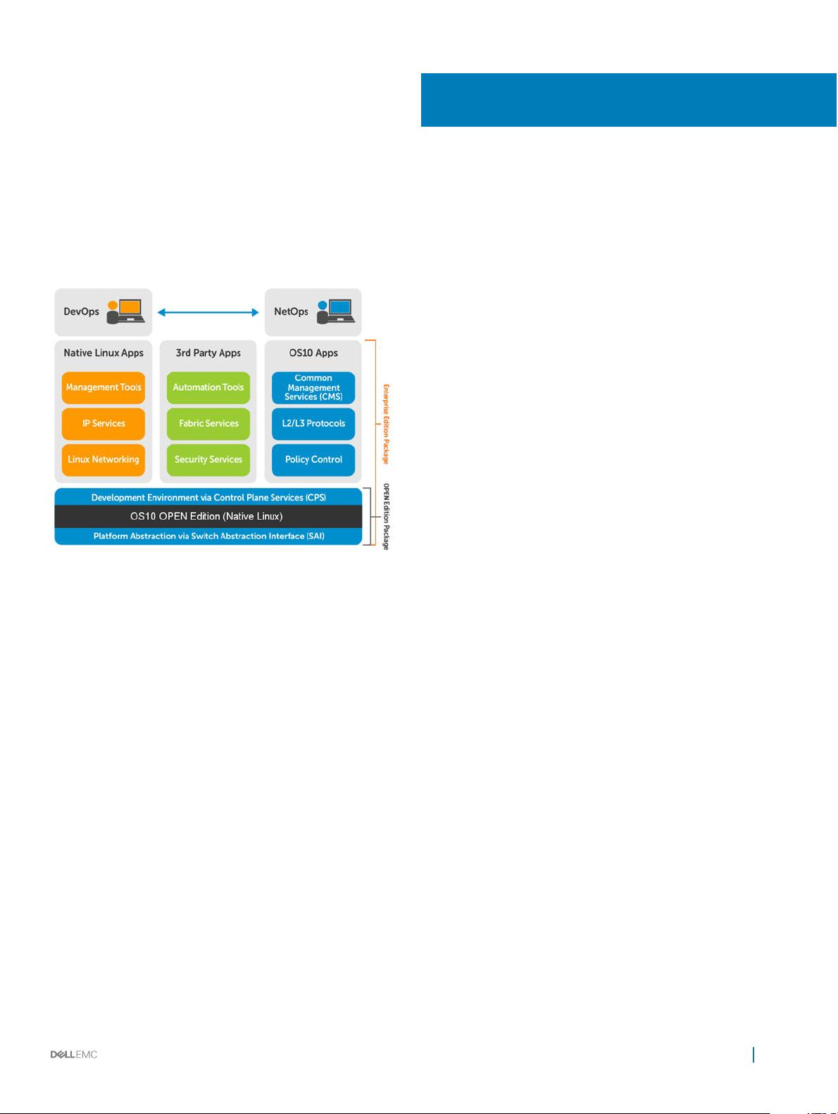
1
Getting Started
Dell EMC Networking OS10 Enterprise Edition is a network operating system supporting multiple architectures and environments. The
networking world is moving from a monolithic stack to a pick-your-own-world. The OS10 solution is designed to allow disaggregation of the
network functionality.
Solutions
• Simplicity to integrate enabled devices into an existing infrastructure
• Provides the most up-to-date security xes which supports a large community of engineers and security experts
• Utilizes an open distribution to simplify the addition of new customized applications or open source applications
Requirements
• Open network installation environment (ONIE)-enabled Dell EMC device
• OS10 software image stored on an HTTP server or universal serial bus (USB) media
• Familiarity with any Linux release
Supported Dell EMC platforms
• S3048-ON
• S4048-ON, S4048T-ON
• S6000-ON, S6010-ON
• S4128F-ON, S4128T-ON
• S4148F-ON, S4148T-ON
• S4148U-ON, S4148FE-ON
Getting Started 19
Page 20

Download OS10 image and license
OS10 Enterprise Edition may come factory-loaded and is available for download from the Dell Digital Locker (DDL). A factory-loaded OS10
image has a perpetual license installed. An OS10 image that you download has a 120-day trial license and requires a perpetual license to run
beyond the trial period. See the Quick Start Guide shipped with your device and My Account FAQs for more information.
Download an OS10 image and license to:
• Re-install the license on a Dell EMC ONIE switch with factory-installed OS10 image and license.
• Install OS10 on a Dell EMC ONIE switch without an operating system (OS) or license installed:
• Device converted from OS9 or a third-party OS after you uninstall (wipe clean) the original OS
• Replacement device received from Dell EMC return material authorization (RMA)
• Upgrade the OS10 image (see Upgrade OS10).
Your OS10 purchase allows you to download software images posted within the rst 90 days of ownership. To extend the software
entitlement, you must have a Dell EMC ProSupport or ProSupport Plus contract on your hardware.
Re-install license on factory-loaded OS10
OS10 Enterprise Edition runs with a perpetual license on an ONIE-enabled device with OS10 factory-installed. The license le is installed on
the switch. If the license becomes corrupted or is wiped out, you must download the license from DDL under the purchaser's account and
reinstall it.
1 Sign in to DDL using your account credentials.
2 Locate the hardware product name with the entitlement ID and order number.
3 Check that the service tag of the purchased device displays in the Assigned To: eld on the Products page.
4 Click Key Available for Download.
5 Select how you want to receive the license key — by email or downloaded to your local device.
6 Click Submit.
7 Save the License.zip le and follow the instructions in Install license to install the license.
Without operating system installed
You can purchase the OS10 Enterprise Edition image with an after point-of-sale (APOS) order for a Dell EMC ONIE-enabled device that
does not have a default operating system or license installed. When the order is fullled, you receive an email notication with a software
entitlement ID, order number, and link to the DDL.
Bind the software entitlement to the service tag of the switch to extend the entitled download period to be the same time as the support
contract. OS10 software entitlement allows you to download OS10 software images posted before the purchase date and within 90 days of
the date, by default.
1 Sign into DDL using your account credentials.
2 Locate the entry for your entitlement ID and order number sent by email, then select the product name.
3 On the Productpage, the Assigned To: eld on the Product tab is blank. Click Key Available for Download.
4 Enter the service tag of the device you purchased the OS10 Enterprise Edition for in the Bind to: and Re-enter ID: elds. This
step binds the software entitlement to the service tag of the switch.
5 Select how you want to receive the license key — by email or downloaded to your local device.
6 Click Submit to download the License.zip le.
7 Select the Available Downloads tab.
8 Select the OS10 Enterprise Edition release to download, then click Download.
9 Read the Dell End User License Agreement. Scroll to the end of the agreement, then click Yes, I agree.
10 Select how you want to download the software les, then click Download Now.
20
Getting Started
Page 21

Once you download the OS10 Enterprise Edition image, unzip the .tar le. Some Windows unzip applications insert extra carriage returns
(CR) or line feeds (LF) when they extract the contents of a .tar le, which may corrupt the downloaded OS10 binary image. Turn o this
option if you use a Windows-based tool to untar an OS10 binary le.
Once you unzip the OS10 Enterprise Edition and download the license, see Installation and Install license for complete installation and
license information.
RMA replacement
A replacement switch comes without an operation system or license installed. If you receive a replacement switch, you must assign the
STAG of the replacement switch to the SW entitlement in DDL and install the OS10 software and license.
Follow the steps for an ONIE switch without an OS installed to download OS10 Enterprise Edition and the license. See Installation and
Install license for complete installation and license information.
Installation
You can install OS10 using an industry-standard open network install environment (ONIE) software image with auto-discovery or using a
manual installation:
• Automatic (zero-touch) installation — ONIE discovers network information including the DHCP server, connects to an image server,
options to point to the server for the image, and downloads and installs an image automatically.
• Manual installation — Manually congure your network information if a DHCP server is not available, or if you install the OS10
software image using USB media.
System setup
Verify that the system is connected correctly before installation:
• Connect a serial cable and terminal emulator to the console serial port — required serial port settings are 115200, 8 data bits, and no
parity.
• Connect the Management port to the network if you prefer downloading an image over a network. To locate the Console port and the
Management port, see the Getting Started Guide shipped with your device or the platform-specic Installation Guide at
www.dell.com/support.
Install OS10
If an operating system (OS) is installed on a device, navigate to the ONIE boot menu. An ONIE-enabled device boots up with pre-loaded
diagnostics and ONIE software.
+--------------------------------------------------------+
|*ONIE: Install OS |
| ONIE: Rescue |
| ONIE: Uninstall OS |
| ONIE: Update ONIE |
| ONIE: Embed ONIE |
| ONIE: Diag ONIE |
+--------------------------------------------------------+
• Install OS — Boots to the ONIE prompt and installs an OS10 image using the automatic discovery process.
• Rescue — Boots to the ONIE prompt and allows for manual installation of an OS10 image or updating ONIE.
• Uninstall OS — Deletes the contents of all disk partitions except ONIE and diagnostics.
• Update ONIE — Installs a new ONIE version.
• Embed ONIE — Formats an empty disk and installs ONIE.
• Diag ONIE — Runs the system diagnostics.
CAUTION
installation, perform Uninstall OS rst to clear the partitions if there is an existing OS on the device. If the problem persists,
contact Dell EMC Technical Support.
: During an automatic or manual OS10 installation, if an error condition occurs that results in an unsuccessful
Getting Started 21
Page 22

Automatic installation
You can automatically (zero-touch) install an OS10 image on a Dell ONIE-enabled device. Once the device successfully boots to ONIE:
Install OS, auto-discovery obtains the hostname, domain name, Management interface IP address, as well as the IP address of the DNS
name server(s) on your network from the DHCP server and DHCP options. The ONIE automatic-discovery process locates the stored
software image, starts installation, then reboots the device with the new software image.
If a USB drive is inserted, auto-discovery searches the USB storage supporting FAT or EXT2 le systems. It also searches SCP, FTP, or
TFTP servers with the default DNS name of the ONIE server. DHCP options are not used to provide the server IP, and the auto discovery
method repeats until a successful software image installation occurs and reboots the switch.
Manual installation
You can manually install an OS10 software image if a DHCP server is not available. If the IP address for the Management port (eth0) is not
automatically discovered, ONIE sets the IP address to 192.168.3.10. You must manually congure the Management port and congure
the software image le to start installation.
1 Save the OS10 software image on an SCP/TFTP/FTP server.
2 Power up the device and select ONIE Rescue for manual installation.
3 (Optional) Stop the DHCP discovery if the device boots to ONIE Install.
$ onie-discovery-stop
4 Congure the IP addresses on the Management port, where x.x.x.x represents your internal IP address. Once you congure the
Management port, the response should be up.
$ ifconfig eth0 x.x.x.x netmask 255.255.0.0 up
5 Install the software on the device. The installation command accesses the OS10 software from the provided SCP, TFTP, or FTP URL,
creates partitions, veries installation, and reboots itself.
$ onie-nos-install image location
The OS10 installer image creates several partitions, including OS10-A (active and default) and OS10-B (standby). After installation
completes, the system automatically reboots and loads OS10.
Install OS10 manually
ONIE:/ # onie-nos-install ftp://x.x.x.x/PKGS_OS10–Enterprise-10.3.xxP.bin
Where x.x.x.x represents the location to download the image le from, and xxP represents the version number of the software to install.
Install using USB drive
You can manually install the OS10 software image using USB media. Verify that the USB storage device supports a FAT or EXT2 le
system. Plug the USB storage device into the USB storage port on the device.
1 Power up the system to automatically boot with the ONIE: Rescue option.
2 (Optional) Stop the ONIE discovery process if the device boots to ONIE: Install.
$ onie-discovery-stop
3 Create a USB mount location on the system.
$ mkdir /mnt/media
4 Mount the USB media plugged in the USB port on the device.
$ mount —t vfat /dev/sdb /mnt/media
5 Install the software from the USB, where /mnt/media species the path where the USB partition is mounted.
$ onie-nos-install /mnt/media/image_file
22
Getting Started
Page 23

The ONIE auto-discovery process discovers the image le at the specied USB path, loads the software image, and reboots.
Log into OS10
To log in to OS10 Enterprise Edition, power up the device and wait for the system to perform a power-on self test (POST). Enter admin
for both the default user name and user password. For better security, change the default admin password during the rst OS10 login.
The system saves the new password for future logins.
OS10 login: admin
Password: admin
Last login: Mon Mar 20 13:58:27 2017 on ttyS0
The programs included with the Debian GNU/Linux system are free software;
the exact distribution terms for each program are described in the
individual files in /usr/share/doc/*/copyright.
Debian GNU/Linux comes with ABSOLUTELY NO WARRANTY, to the extent
permitted by applicable law.
-*-*-*-*-*-*-*-*-*-*-*-*-*-*-*-*-*-*-*-*-*-*-*-*-*-*-*-*-*-*-*-*-
-* Dell EMC Network Operating System (OS10) *-
-* *-
-* Copyright (c) 1999-2017 by Dell Inc. All Rights Reserved. *-
-* *-
-*-*-*-*-*-*-*-*-*-*-*-*-*-*-*-*-*-*-*-*-*-*-*-*-*-*-*-*-*-*-*-*-
This product is protected by U.S. and international copyright and
intellectual property laws. Dell EMC and the Dell EMC logo are
trademarks of Dell Inc. in the United States and/or other
jurisdictions. All other marks and names mentioned herein may be
trademarks of their respective companies.
OS10#
Install OS10 license
If OS10 is factory-loaded on your switch, you do not need to install an OS10 license. If you download OS10 on a trial basis, OS10 comes with
a 120-day trial license. To continue with uninterrupted use, purchase and install a perpetual license to avoid the OS10 device rebooting every
72 hours.
After you install OS10 and log in, install the license to run the OS10 Enterprise Edition beyond the trial license period. See Download OS10
image and license for complete information. The OS10 license is installed in the /mnt/license directory.
1 Download the License.zip le from DDL as described in Download OS10 image and license.
2 Open the zip le and locate the license le in the Dell folder. Copy the license le to a local or remote workstation.
3 Install the license le from the workstation in EXEC mode.
license install {ftp: | http: | localfs: | scp: | sftp: | tftp: | usb:} filepath/filename
• ftp://userid:passwd@hostip/filepath — Copy from a remote FTP server
• http://hostip/filepath — Copy from a remote HTTP server
• http://hostip — Send request to a remote HTTP server.
• localfs://filepath — Install from a local le directory.
• scp://userid:passwd@hostip/filepath — Copy from a remote SCP server.
• sftp://userid:passwd@hostip/filepath — Copy from a remote SFTP server.
• tftp://hostip/filepath — Copy from a remote TFTP server.
• usb://filepath — Install from a le directory on a storage device connected to the USB storage port on the switch.
• filepath/filename — Enter the directory path where the license le is stored.
Getting Started
23
Page 24

Install license
OS10# license install scp://user:userpwd@10.1.1.10/CFNNX42-NOSEnterprise-License.xml
License installation success.
Verify license installation
OS10# show license status
System Information
-----------------------------------------Vendor Name : DELL
Product Name : S4048-ON
Hardware Version: A00
Platform Name : S4048-ON
PPID : CN0M68YC2829855M0133
Service Tag : CFNNX42
License Details
---------------Software : OS10-Enterprise
Version : 10.3.0E
License Type : PERPETUAL License
Duration: Unlimited License
Status : Active
License location: /mnt/license/CFNNX42.lic
------------------------------------------
Troubleshoot license installation failure
An error message displays if the installation fails.
License installation failed
1 Verify the installation path to the local or remote location you tried to download the license from.
2 Check the log on the remote server to see why the FTP or TFTP le transfer failed.
3 Ping the remote server from the switch — use the ping and traceroute commands to test network connectivity. If the ping fails:
• Check if a Management route is congured on the switch. If not, use the management route command to congure a route to
the server network.
• Install the server with the license le on the same subnet as switch.
4 Check if the server is up and running.
Remote access
You can remotely access the OS10 command-line interface (CLI) and the Linux shell. When you install OS10 the rst time, connect to the
switch using the serial port.
Congure remote access
• Congure the Management port IP address
• Congure a default route to the Management port
• Congure a user name and password
Remote access OS10 CLI
1 Open an SSH session using the IP address of the device. You can also use PuTTY or a similar tool to access the device remotely.
ssh admin@ip-address
password: admin
2 Enter admin for both the default user name and password to log into OS10. You are automatically placed in EXEC mode.
OS10#
24
Getting Started
Page 25

Remote access Linux shell
ssh linuxadmin@ip-address
password: linuxadmin
Congure Management IP address
To remotely access OS10, assign an IP address to the Management port.
1 Congure the management interface from CONFIGURATION mode.
interface mgmt node/slot/port
2 Congure an IPv4 or IPv6 address on the Management interface in INTERFACE mode.
ip address A.B.C.D/mask
ipv6 address A:B/prefix-length
3 Enable the Management interface in INTERFACE mode.
no shutdown
Congure Management interface
OS10(config)# interface mgmt 1/1/1
OS10(conf-if-ma-1/1/1)# ip address 10.1.1.10/24
OS10(conf-if-ma-1/1/1)# no shutdown
Management Route Conguration
WARNING
or IPv6 address and static route on a front-end port interface.
To set up remote access to OS10, congure a management route after you assign an IPv4 or IPv6 address to the Management port. The
default management route is the path used by a Management port to communicate with a dierent network. Management routes are
separate from IPv4 and IPv6 routes and are only used to manage the system through the Management port.
management route 192.168.100.0/24 1.1.1.1
ip route 192.168.100.0/24 2.2.2.2
management route 192.168.200.0/24 managementethernet
ip route 192.168.200.0/24 interface ethernet 1/1/1
Congure a management route to the network from which you access the system in CONFIGURATION mode. Repeat the command to
congure multiple routes for the Management interface.
management route {ipv4-address/mask | ipv6-address/prefix-length}
{forwarding-router-address | managementethernet}
• ipv4-address/mask — Enter an IPv4 network address in dotted-decimal format (A.B.C.D), then a subnet mask in /prex-length
format (/xx).
• ipv6-address/prefix-length — Enter an IPv6 address in x:x:x:x::x format with the prex length in /x format (prex range is /0
to /128).
• forwarding-router-address — Enter the next-hop IPv4/IPv6 address of a forwarding router for network trac from the
Management port.
• managementethernet — Congures the Management port as the interface for the route, and forces the route to be associated
with the Management interface.
: Avoid conguring an IPv4 or IPv6 address and a static route for the management interface that conict with an IPv4
Congure management route
OS10(config)# management route 10.10.20.0/24 10.1.1.1
OS10(config)# management route 172.16.0.0/16 managementethernet
Getting Started
25
Page 26

Congure user name and password
To set up remote access to OS10, create a new user name and password after you congure the Management port and default route.
• Create a user name and password in CONFIGURATION mode.
username username [encryption-type] password password
• username username — Enter a text string (up to 63 alphanumeric characters).
• encryption-type — (Optional) Enter an encryption type for the password:
• 0 — Store the password as clear text (default).
• 5 — Encrypt the password using an MD5 hash algorithm.
• 7 — Encrypt the password using a DES hash algorithm.
• 8 — Encrypt the password using a SHA2 hash algorithm.
• password password — Enter a text string (up to 32 alphanumeric characters).
Create user name and password
OS10(config)# username test password *****
Upgrade OS10
To upgrade OS10, download a new OS10 Enterprise Edition image from the DDL.
1 Sign into DDL using your account credentials.
2 Locate the entry for your entitlement ID and order number, then select the product name.
3 Select the Available Downloads tab on the Product page.
4 Select the OS10 Enterprise Edition image to download, then click Download.
5 Read the Dell End User License Agreement, then scroll to the end of the agreement and click Yes, I agree.
6 Select how you want to download the software les, then click Download Now.
Install the OS10 image on an ONIE-enabled switch with an installed OS10 license. See Install OS10 license for complete instructions.
CLI Basics
The OS10 command-line interface (CLI) is the software interface you use to access a device running the software — from the console or
through a network connection. The CLI is an OS10-specic command shell that runs on top of a Linux-based operating system kernel. By
leveraging industry-standard tools and utilities, the CLI provides a powerful set of commands that you can use to monitor and congure
devices running OS10.
User accounts
OS10 denes two categories of user accounts — use admin for both the username and password to log into the CLI, or use
linuxadmin to log into the Linux shell.
26
Getting Started
Page 27

Key CLI features
Consistent
command names
Available commands Information about available commands is provided at each level of the CLI command hierarchy. You can enter a
Command
completion
Commands that provide the same type of function have the same name, regardless of the portion of the system
on which they are operating. For example, all show commands display software information and statistics, and all
clear commands erase various types of system information.
question mark (?) at any level and view a list of the available commands, along with a short description of each
command.
Command completion for command names (keywords) and for command options is available at each level of the
hierarchy. To complete a command or option that you have partially entered, press the Tab key or the Spacebar. If
the partially entered letters being a string that uniquely identies a command, the complete command name
appears. A beep indicates that you have entered an ambiguous command, and the possible completions display.
Completion also applies to other strings, such as lenames, interface names, usernames, and conguration
statements.
CLI command modes
The OS10 CLI has two top-level modes:
• EXEC mode — Used to monitor, troubleshoot, check status, and network connectivity.
• CONFIGURATION mode — Used to congure network devices.
When you enter CONFIGURATION mode, you are changing the current operating conguration, called the running conguration. By
default, all conguration changes are automatically saved to the running conguration.
You can change this default behavior by switching to the transaction-based conguration mode. To switch to the transaction-based
conguration mode, enter the start transaction command. When you switch to the transaction-based conguration mode, you are
updating the candidate conguration. Changes to the candidate conguration are not added to the running conguration until you commit
them, which activates the conguration. The start transaction command applies only to the current session. Changing the
conguration mode of the current session to the transaction-based mode does not aect the conguration mode of other CLI sessions.
• After you explicitly enter the commit command to save changes to the candidate conguration, the session switches back to the
default behavior of automatically saving the conguration changes to the running conguration.
• When a session terminates while in the transaction-based conguration mode, and you have not entered the commit command, the
changes are maintained in the candidate conguration. You can start a new transaction-based conguration session and continue with
the remaining conguration changes.
• All sessions in the transaction-based conguration mode update the same candidate conguration. When you enter the commit
command on any session in the transaction-based conguration mode or you make conguration changes on any session in the non-
transaction-based mode, you also commit the changes made to the candidate conguration in all other sessions running in the
transaction-based conguration mode. This implies that inconsistent conguration changes may be applied to the running conguration.
Dell EMC recommends that you only make conguration changes on a single CLI session at a time.
• When you enter the lock command in a CLI session, conguration changes are disabled on all other sessions, whether they are in the
transaction-based conguration mode or the non-transaction-based conguration mode. For more information, see
conguration.
Candidate
CLI command hierarchy
CLI commands are organized in a hierarchy. Commands that perform a similar function are grouped together under the same level of
hierarchy. For example, all commands that display information about the system and the system software are grouped under the show
Getting Started
27
Page 28
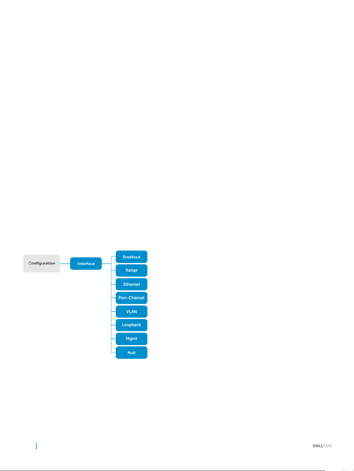
system command, and all commands that display information about the routing table are grouped under the show route-map
command.
CLI command categories
There are several broad groups of CLI commands available:
set Controls the CLI environment and congure the CLI screen.
ssh Connects to other network systems or to open secure shell connections.
copy Copies les from one location on a device to another, from a device to a remote system, or from a remote system
to a device.
congure Enters CONFIGURATION mode to congure routing protocols, interfaces, network management, and user access.
exit Moves up one command mode. Use the end command to go directly to EXEC mode.
quit Leaves or exits the CLI.
CONFIGURATION Mode
When you initially log in to OS10, you are automatically placed in EXEC mode by default. To access CONFIGURATION mode, enter the
configure terminal command. Use CONFIGURATION mode to manage interfaces, protocols, and features.
Interface mode is a sub-mode of CONFIGURATION mode. Interface mode is where you congure Layer 2 and Layer 3 protocols, and IPv4
and IPv6 services specic to an interface:
• Physical interfaces include the Management interface and Ethernet ports
• Logical interfaces include loopback, port-channel, and virtual local area networks (VLANs)
From CONFIGURATION mode, you can also congure L2 and L3 protocols with a specic protocol-conguration mode, such as spanning-
tree protocol (STP) or border gateway protocol (BGP).
Command help
To view a list of valid commands for any CLI mode, enter ? or the help command.
28
Getting Started
Page 29

1 Enter ? to view the commands available in EXEC mode.
OS10# ?
alarm Alarm commands
alias Set alias for a command
batch Batch Mode
boot Tell the system where to access the software image at bootup
clear Clear command
clock Configure the system clock
commit Commit candidate configuration
configure Enter configuration mode
copy Perform a file copy operation
debug Debug command
delete Perform a file delete operation on local file system
dir Show the list of files for the specified system folder
discard Discard candidate configuration
exit Exit from the CLI
generate Command to generate executed functionality
help Display available commands
image Image commands
kill-session Kill a CLISH session
license License and digital fulfillment commands
location-led Set location LED
lock Lock candidate configuration
move Perform a file move/rename operation on local filesystem
no No commands under exec mode
ping ping -h shows help
ping6 ping6 -h shows help
reload Reboot Dell EMC Networking Operating System
show Show running system information
start Activate transaction based configuration
support-assist-activity Support Assist related activity
system System command
terminal Set terminal settings
traceroute traceroute --help shows help
unlock Unlock candidate configuration
validate Validate candidate configuration
write Copy from current system configuration
2 Enter CONFIGURATION mode.
OS10# configure terminal
OS10(config)#
3 Enter ? to show the commands available in CONFIGURATION mode.
OS10(config)# ?
aaa To configure AAA
alias Set alias for a command
class-map Configure class map
clock Configure clock parameters
control-plane Control-plane configuration
crypto Crypto commands
dcbx DCBX commands
dot1x Configure dot1x global information
end Exit to the exec Mode
eula-consent eula-consent configuration
exec-timeout Set timeout (in seconds) for all CLI sessions
exit Exit from current mode
feature Enable feature
hardware Hardware forwarding table mode configurations
hash-algorithm Hash algorithm configurations
help Display available commands
host-description Set the system host description
hostname Set the system hostname
interface Select an interface
ip Global IP configuration subcommands
ipv6 Configure ipv6
iscsi enable iscsi globally
lacp LACP commands
link-bundle-utilization Configure link bundle utilization trigger threshold
lldp Configure LLDP parameters
Getting Started
29
Page 30

load-balancing Load balancing configurations
logging Logging commands
mac MAC Address Table Configuration Subcommands
management management interface commands
monitor Create a session for monitoring traffic
no To delete / disable commands in config mode
ntp Configure NTP
policy-map Configure policy map
qos-map Configure QoS map
radius-server Specify radius server host and configure its communication
pa
rameters
route-map Creates route-map
router Enable a routing process
sflow Configure sflow parameters
snmp-server Configure SNMP server
spanning-tree Spanning Tree Subsystem
support-assist Support Assist feature configuration
system System configuration
track Configure object tracking
trust Configure trust
username Create or modify users
vlt-domain VLT domain configurations
vrrp Configure VRRP global attributes
Check device status
Use show commands to check the status of a device and monitor activities.
• Enter show ? from EXEC mode to view a list of commands to monitor a device.
OS10# show ?
alarms Display all current alarm situation in the system
alias Show list of aliases
boot Show boot information
candidate-configuration Current candidate configuration
class-map Show QoS class-map configuration
cli-session This command is deprecated please use 'show sessions' instead
clock Show the system date and time
command-history shows command history of the current user
control-plane Display control-plane related informations
copy-file Show file copy operation information
diag Show diagnostic information for port adapters/modules
diff Display differences between two configuration set
dot1x Show dot1x information
environment Show the environmental information of the system
eula-consent Shows eula-consent for various modules
exec-timeout Show the timeout value of CLI session (in seconds)
file Display file content in specified location
hardware Show hardware information
hash-algorithm Show hash algorithm information
hosts show information about DNS
image Show image information
interface Interface status and configuration
inventory Show the system inventory information
ip show IP commands
ipv6 Display IPv6 neighbor information
iscsi Show iscsi
lacp Show LACP information
license Show license and digital fulfillment related information
link-bundle-utilization Display the link-bundle utilization for the interfaces in the
bundle
lldp Show lldp
load-balance Show global traffic load-balance configuration
logging Show logging messages
mac MAC forwarding table
monitor Show port monitoring sessions
30
Getting Started
Page 31

network-policy Show network policy
ntp NTP associations
parser-tree Show parser tree
policy-map Show policy-map information
port-channel LAG status and configuration
processes Show processes statistics
qos Show ingress or egress QoS configuration
queuing Show egress QoS counters
route-map Show route map information
running-configuration Current operating configuration
sessions Show active management sessions
sflow Show sflow
spanning-tree Show spanning tree information
startup-configuration Contents of startup configuration
storm-control Show storm control configuration
support-assist Shows information about the support assist module
system Show system status information
tech-support Collection of show commands
terminal Show terminal configurations for this session
trace Show trace messages
track Show object tracking information
uptime Show the system uptime
users Show the current list of users logged into the system , and show
the session id
version Show the software version on the system
vlan Vlan status and configuration
vlt Show VLT domain info
vrrp VRRP group status
• Enter show command-history from EXEC mode to view trace messages for each executed command.
OS10# show command-history
1 Thu Apr 20 19:44:38 UTC 2017 show vlan
2 Thu Apr 20 19:47:01 UTC 2017 admin
3 Thu Apr 20 19:47:01 UTC 2017 monitor hardware-components controllers view 0
4 Thu Apr 20 19:47:03 UTC 2017 system general info system-version view
5 Thu Apr 20 19:47:16 UTC 2017 admin
6 Thu Apr 20 19:47:16 UTC 2017 terminal length 0
7 Thu Apr 20 19:47:18 UTC 2017 terminal datadump
8 Thu Apr 20 19:47:20 UTC 2017 %abc
9 Thu Apr 20 19:47:22 UTC 2017 switchshow
10 Thu Apr 20 19:47:24 UTC 2017 cmsh
11 Thu Apr 20 19:47:26 UTC 2017 show version
12 Thu Apr 20 19:47:28 UTC 2017 cmsh
13 Thu Apr 20 19:47:30 UTC 2017 show version
14 Thu Apr 20 19:47:32 UTC 2017 show system
15 Fri Apr 21 12:35:31 UTC 2017 BIOS 3.20.0.3
• Enter show system from EXEC mode to view the system status information.
OS10# show system
Node Id : 1
MAC : 00:0c:29:db:91:96
Number of MACs : 256
Up Time : 2 days 02:48:18
-- Unit 1 -Status : up
System Identifier : 1
Down Reason : user-triggered
System Location LED : off
Required Type : S6000
Current Type : S6000
Hardware Revision : A01
Software Version : 10.2.9999E
Bios Version : None
Physical Ports : 32x40GbE
BIOS : 3.33.0.2
System CPLD : 0.3
Master CPLD : 0.4
Slave CPLD : 0.2
Getting Started
31
Page 32

-- Power Supplies -PSU-ID Status Type AirFlow Fan Speed(rpm) Status
---------------------------------------------------------------1 up DC REVERSE 1 7200 up
2 up DC REVERSE 1 7200 up
-- Fan Status -FanTray Status AirFlow Fan Speed(rpm) Status
---------------------------------------------------------------1 up REVERSE 1 7000 up
2 7000 up
2 up REVERSE 1 7000 up
2 7000 up
3 up REVERSE 1 7000 up
2 7000 up
Candidate conguration
When you enter OS10 conguration commands in the transaction-based conguration mode, changes do not take eect immediately and
are stored in the candidate conguration. The conguration changes become active on the network device only after you commit the
changes with the commit command. Changes in the candidate conguration are validated and applied to the running conguration.
The candidate conguration allows you to avoid introducing errors during an OS10 conguration session. You can make changes and then
check them before committing them to the active, running conguration on the network device.
Use the show diff command to check dierences between the running conguration and the candidate conguration. After comparing
the two, you can decide if you would like to commit the changes to the running conguration. Use the discard command to delete
uncommitted changes.
• Enter show ? from EXEC mode to view a list of commands to monitor a device.
OS10# show ?
aaa Current candidate aaa configuration
access-list Current candidate access-list configuration
as-path Current candidate as-path configuration
bgp Current candidate bgp configuration
class-map Current candidate class-map configuration
community-list Current candidate community-list configuration
compressed Current candidate configuration in compressed format
control-plane Current candidate control-plane configuration
dot1x Current candidate dot1x configuration
extcommunity-list Current candidate extcommunity-list configuration
interface Current candidate interface configuration
lacp Current candidate lacp configuration
lldp Current candidate lldp configuration
logging Current candidate logging configuration
monitor Current candidate monitor session configuration
ospf Current candidate ospf configuration
ospfv3 Current candidate ospfv3 configuration
policy-map Current candidate policy-map configuration
prefix-list Current candidate prefix-list configuration
qos-map Current candidate qos-map configuration
radius-server Current candidate radius-server configuration
route-map Current candidate route-map configuration
sflow Current candidate sFlow configuration
snmp Current candidate snmp configuration
spanning-tree Current candidate spanning-tree configuration
support-assist Current candidate support-assist configuration
system-qos Current candidate system-qos configuration
trust-map Current candidate trust-map configuration
32
Getting Started
Page 33

users Current candidate users configuration
vlt Current candidate vlt domain configuration
View compressed candidate conguration
OS10# show candidate-configuration compressed
interface breakout 1/1/1 map 40g-1x
interface breakout 1/1/2 map 40g-1x
interface breakout 1/1/3 map 40g-1x
interface breakout 1/1/4 map 40g-1x
interface breakout 1/1/5 map 40g-1x
interface breakout 1/1/6 map 40g-1x
interface breakout 1/1/7 map 40g-1x
interface breakout 1/1/8 map 40g-1x
interface breakout 1/1/9 map 40g-1x
interface breakout 1/1/10 map 40g-1x
interface breakout 1/1/11 map 40g-1x
interface breakout 1/1/12 map 40g-1x
interface breakout 1/1/13 map 40g-1x
interface breakout 1/1/14 map 40g-1x
interface breakout 1/1/15 map 40g-1x
interface breakout 1/1/16 map 40g-1x
interface breakout 1/1/17 map 40g-1x
interface breakout 1/1/18 map 40g-1x
interface breakout 1/1/19 map 40g-1x
interface breakout 1/1/20 map 40g-1x
interface breakout 1/1/21 map 40g-1x
interface breakout 1/1/22 map 40g-1x
interface breakout 1/1/23 map 40g-1x
interface breakout 1/1/24 map 40g-1x
interface breakout 1/1/25 map 40g-1x
interface breakout 1/1/26 map 40g-1x
interface breakout 1/1/27 map 40g-1x
interface breakout 1/1/28 map 40g-1x
interface breakout 1/1/29 map 40g-1x
interface breakout 1/1/30 map 40g-1x
interface breakout 1/1/31 map 40g-1x
interface breakout 1/1/32 map 40g-1x
ipv6 forwarding enable
username admin password $6$q9QBeYjZ$jfxzVqGhkxX3smxJSH9DDz7/3OJc6m5wjF8nnLD7/VKx8SloIhp4NoGZs0I/
UNwh8WVuxwfd9q4pWIgNs5BKH. role sysadmin
aaa authentication local
snmp-server contact http://www.dell.com/support
!
interface range ethernet 1/1/1-1/1/32
switchport access vlan 1
no shutdown
!
interface vlan 1
no shutdown
!
interface mgmt1/1/1
ip address dhcp
no shutdown
ipv6 enable
ipv6 address autoconfig
!
support-assist
!
policy-map type application policy-iscsi
!
class-map type application class-iscsi
!
class-map type qos class-trust
View compressed running conguration
OS10# show running-configuration compressed
interface breakout 1/1/1 map 40g-1x
Getting Started
33
Page 34

interface breakout 1/1/2 map 40g-1x
interface breakout 1/1/3 map 40g-1x
interface breakout 1/1/4 map 40g-1x
interface breakout 1/1/5 map 40g-1x
interface breakout 1/1/6 map 40g-1x
interface breakout 1/1/7 map 40g-1x
interface breakout 1/1/8 map 40g-1x
interface breakout 1/1/9 map 40g-1x
interface breakout 1/1/10 map 40g-1x
interface breakout 1/1/11 map 40g-1x
interface breakout 1/1/12 map 40g-1x
interface breakout 1/1/13 map 40g-1x
interface breakout 1/1/14 map 40g-1x
interface breakout 1/1/15 map 40g-1x
interface breakout 1/1/16 map 40g-1x
interface breakout 1/1/17 map 40g-1x
interface breakout 1/1/18 map 40g-1x
interface breakout 1/1/19 map 40g-1x
interface breakout 1/1/20 map 40g-1x
interface breakout 1/1/21 map 40g-1x
interface breakout 1/1/22 map 40g-1x
interface breakout 1/1/23 map 40g-1x
interface breakout 1/1/24 map 40g-1x
interface breakout 1/1/25 map 40g-1x
interface breakout 1/1/26 map 40g-1x
interface breakout 1/1/27 map 40g-1x
interface breakout 1/1/28 map 40g-1x
interface breakout 1/1/29 map 40g-1x
interface breakout 1/1/30 map 40g-1x
interface breakout 1/1/31 map 40g-1x
interface breakout 1/1/32 map 40g-1x
ipv6 forwarding enable
username admin password $6$q9QBeYjZ$jfxzVqGhkxX3smxJSH9DDz7/3OJc6m5wjF8nnLD7/VKx8SloIhp4NoGZs0I/
UNwh8WVuxwfd9q4pWIgNs5BKH. role sysadmin
aaa authentication local
snmp-server contact http://www.dell.com/support
!
interface range ethernet 1/1/1-1/1/32
switchport access vlan 1
no shutdown
!
interface vlan 1
no shutdown
!
interface mgmt1/1/1
ip address dhcp
no shutdown
ipv6 enable
ipv6 address autoconfig
!
support-assist
!
policy-map type application policy-iscsi
!
class-map type application class-iscsi
!
class-map type qos class-trust
Show dierence between candidate and running congurations
OS10# show diff candidate-configuration running-configuration
OS10#
NOTE
: If the OS10# prompt does not return output, the candidate-configuration and running-configuration les
match.
34 Getting Started
Page 35

Prevent conguration changes
You can prevent conguration changes on sessions other than the current CLI session using the lock command. Use the lock and
unlock commands in EXEC mode to respectively prevent and allow conguration changes on other sessions. When you enter the lock
command on a CLI session, users cannot make conguration changes across any other active CLI sessions. When you close the CLI session
on which you entered the lock command, conguration changes are automatically allowed on all other sessions.
Lock conguration changes
OS10# lock
Unlock conguration changes
OS10# unlock
Change to transaction-based conguration
To change to transaction-based conguration mode for a session, enter the start transaction command
1 Change to transaction-based conguration in EXEC mode.
start transaction
2 Enable, for example, an interface from INTERFACE mode.
interface ethernet 1/1/1/
no shutdown
3 Save the conguration.
do commit
NOTE
: After you enter the do commit command, the current session switches back to the default behavior of
committing all conguration changes automatically.
Save conguration changes manually
OS10# start transaction
OS10# configure terminal
OS10(config)#
OS10(config)# interface ethernet 1/1/1
OS10(config-if-eth1/1/1)# no shutdown
OS10(config-if-eth1/1/1)# do commit
Back up or restore conguration
The running conguration contains the current system conguration which you can copy to and from a server for backup and restore
purposes. You can also copy the running conguration locally to and from the home: and cong: directories on the switch.
The startup conguration le is maintained in the cong system folder and is called system.xml. When you make changes to conguration
les, use the reload command to reboot OS10 with the updated conguration.
Copy the running conguration to the startup conguration
OS10# copy running-configuration startup-configuration
View /cong directory
OS10# dir config
Directory contents for folder: config
Getting Started
35
Page 36

Date (modified) Size (bytes) Name
--------------------- ------------ -----------
2017-04-26T15:23:46Z 26704 startup.xml
Backup startup le
OS10# copy config://startup.xml config://backup-9-28.xml
Backup startup le to server
OS10# copy config://startup.xml scp://userid:password@hostip/backup-9-28.xml
Restore startup le from backup
OS10# copy config://backup-9-28.xml config://startup.xml
OS10# reload
Restore startup le from server
OS10# copy scp://admin:admin@hostip/backup-9-28.xml config://startup.xml
OS10# reload
Reload system image
Reboot the system manually using the reload command in EXEC mode. You are prompted to conrm the operation.
OS10# reload
System configuration has been modified. Save? [yes/no]:yes
Saving system configuration
Proceed to reboot the system? [confirm yes/no]:yes
To congure the OS10 image loaded at the next system boot, enter the boot system command in EXEC mode.
boot system {active | standby}
• Enter active to load the primary OS10 image stored in the A partition.
• Enter standby to load the secondary OS10 image stored in the B partition.
Set next boot image
OS10# boot system standby
OS10# show boot
Current system image information:
===================================
Type Boot Type Active Standby Next-Boot
-------------------------------------------------------------------
Node-id 1 Flash Boot [A] 10.2.9999E [B] 10.2.9999E [B] standby
Filter show commands
You can lter show command output to view specic information, or start the command output at the rst instance of a regular expression
or phrase.
display-xml
except Shows only text that does not match a pattern
nd Searches for the rst occurrence of a pattern and display all the subsequent congurations
grep Shows only text that matches a pattern
36 Getting Started
Displays in XML format.
Page 37

no-more Does not paginate output
save Saves the output to a le
Display all output
OS10# show running-configuration | no-more
Alias command
The alias command allows you to create shortcuts for commonly used or long commands, and execute long commands along with the
parameters.
The alias supports the following modes:
• Persistent mode — The alias is persistent and can be used in other sessions as well. The aliases created in the Conguration mode are
persistent.
• Non-persistent mode — The alias can be used only within the session. Once the session is closed, the alias is removed from the
system. The aliases created in the Exec mode are non-persistent.
NOTE: You cannot use the existing keywords, parameters, and existing short form of keywords as alias names, nor can you create
a shortcut for the aliascommand.
• Create an alias in EXEC or CONFIGURATION mode — EXEC mode for non-persistent and CONFIGURATION mode for persistent
aliases. The alias value is the actual command where you can use $n to enter the input parameters. You can substitute $n with either
numbers ranging from 1 to 9 or with an asterisk (*) and enter the parameters while executing the commands using the alias. When you
are using asterisk (*), you can use multiple input parameters. The maximum number of input parameters is 9.
alias alias-name alias-value
• Execute the commands using the alias in the respective modes.
• View the current aliases.
show alias [brief | detail]
• Use the no form of the command to delete an alias.
no alias alias-name
Create alias
OS10# alias showint "show interface $*"
OS10(config)# alias goint "interface ethernet $1"
View alias output for showint
OS10# showint status
---------------------------------------------------------------------------------
Port Description Status Speed Duplex Mode Vlan Tagged-Vlans
---------------------------------------------------------------------------------
Eth 1/1/1 up 40G A 1 Eth 1/1/2 up 40G A 1 Eth 1/1/3 up 40G A 1 Eth 1/1/4 up 40G A 1 Eth 1/1/5 up 40G A 1 Eth 1/1/6 up 40G A 1 Eth 1/1/7 up 40G A 1 Eth 1/1/8 up 40G A 1 Eth 1/1/9 up 40G A 1 Eth 1/1/10 up 40G A 1 Eth 1/1/11 up 40G A 1 Eth 1/1/12 up 40G A 1 Eth 1/1/13 up 40G A 1 Eth 1/1/14 up 40G A 1 Eth 1/1/15 up 40G A 1 Eth 1/1/16 up 40G A 1 Eth 1/1/17 up 40G A 1 -
Getting Started
37
Page 38

Eth 1/1/18 up 40G A 1 Eth 1/1/19 up 40G A 1 Eth 1/1/20 up 40G A 1 Eth 1/1/21 up 40G A 1 Eth 1/1/22 up 40G A 1 Eth 1/1/23 up 40G A 1 Eth 1/1/24 up 40G A 1 Eth 1/1/25 up 40G A 1 Eth 1/1/26 up 40G A 1 Eth 1/1/27 up 40G A 1 Eth 1/1/28 up 40G A 1 Eth 1/1/29 up 40G A 1 Eth 1/1/30 up 40G A 1 Eth 1/1/31 up 40G A 1 Eth 1/1/32 up 40G A 1 -
--------------------------------------------------------------------------------
View alias output for goint
OS10(config)# goint 1/1/1
OS10(conf-if-eth1/1/1)#
View alias information
OS10# show alias
Name Type
---- ----
govlt Config
goint Config
shconfig Local
showint Local
shver Local
Number of config aliases : 2
Number of local aliases : 3
View alias information brief (displays the rst 10 characters of the alias value)
OS10# show alias brief
Name Type Value
---- ---- -----
govlt Config "vlt-domain..."
goint Config "interface ..."
shconfig Local "show runni..."
showint Local "show inter..."
shver Local "show versi..."
Number of config aliases : 2
Number of local aliases : 3
View alias information in detail (displays the entire alias value)
OS10# show alias detail
Name Type Value
---- ---- -----
govlt Config "vlt-domain $1"
goint Config "interface ethernet $1"
shconfig Local "show running-configuration"
showint Local "show interface $*"
shver Local "show version"
Number of config aliases : 2
Number of local aliases : 3
Delete alias
OS10# no alias showint
OS10(config)# no alias goint
38
Getting Started
Page 39

Batch mode commands
You can create a batch le to simplify routine or repetitive tasks. A batch le is an unformatted text le that contains two or more
commands and has a .cmd le name extension.
You can use vi or any other editor to create the .cmd le, then use the batch command to execute the le. To execute a series of
commands in a le in batch mode (non-interactive processing), use the batch command. OS10 automatically commits all commands in a
batch le — you do not have to enter the commit command.
• Create a batch le (b.cmd) on a remote device by entering a series of commands.
interface ethernet 1/1/4
no switchport
ip address 172.17.4.1/24
no shutdown
• Copy the command le on the remote device to your switch, such as to your home directory.
OS10# copy scp://os10user:os10passwd@10.11.222.1:/home/os10/b.cmd home://b.cmd
OS10# dir home
Directory contents for folder: home
Date (modified) Size (bytes) Name
--------------------- ------------ -----------------------------------------2017-02-15T19:25:35Z 77
b.cmd
...
• Execute the batch le using the batch command in EXEC mode.
OS10# batch b.cmd
OS10# Feb 15 19:26:1: %Dell EMC (OS10) %Node.1-Unit.1:PRI:OS10 %log-notice:IP_ADDRESS_ADD: IP
Address add is successful.:IP 172.17.4.1/24 added successfully
• (Optional) Verify the new commands in the running conguration.
OS10# show running-configuration interface ethernet 1/1/4
!
interface ethernet1/1/4
ip address 172.17.4.1/24
no switchport
no shutdown
Linux shell commands
You can execute a single command, or a series of commands using a batch le from the Linux shell.
• Use the -c option to run a single command.
admin@OS10:/opt/dell/os10/bin$ clish -c "show version"
New user admin logged in at session 10
Dell Networking OS10-Enterprise
Copyright (c) 1999-2017 by Dell Inc. All Rights Reserved.
OS Version: 10.2.9999E
Build Version: 10.2.9999E(3764)
Build Time: 2017-02-09T06:02:58.087-08:00
System Type: S6000-ON
Architecture: x86_64
Up Time: 11:53:11
User admin logged out at session 10
admin@OS10:/opt/dell/os10/bin$
Getting Started
39
Page 40

• Use the -B option along with a batch le to execute a series of commands.
configure terminal
router bgp 100
neighbor 100.1.1.1
remote-as 104
no shutdown
Execute the batch le.
admin@OS10:/opt/dell/os10/bin$ clish -B ~/batch_cfg.txt
New user admin logged in at session 15
Verify the BGP conguration executed by the batch le.
admin@OS10:/opt/dell/os10/bin$ clish -c "show running-configuration bgp"
New user admin logged in at session 16
!
router bgp 100
!
neighbor 100.1.1.1
remote-as 104
no shutdown
admin@OS10:/opt/dell/os10/bin$
User admin logged out at session 16
SSH commands
You can execute commands remotely using an SSH session. This is supported only for show commands.
• Enter the show command along with SSH.
$ ssh admin@ip-address show-command
$ ssh admin@10.11.98.39 "show version"
admin@10.11.98.39's password:
Dell EMC Networking OS10-Enterprise
Copyright (c) 1999-2017 by Dell Inc. All Rights Reserved.
OS Version: 10.3.0000E
Build Version: 10.3.0000E(4181)
Build Time: 2017-04-02T18:00:38.375-07:00
System Type: S6000-ON
Architecture: x86_64
Up Time: 1 week 05:36:38
OS9 environment commands
You can congure commands in an OS9 environment by using the feature config-os9-style command. The current release
supports VLAN tagging and port-channel grouping commands.
• VLAN Interface mode
• tagged
• no tagged
• untagged
• no untagged
• Port-channel Interface mode:
• channel-member
40
Getting Started
Page 41

• no channel-member
• Enable the feature to congure commands in an OS9 environment in CONFIGURATION mode.
OS10(config)# feature config-os9-style
OS10(config)# exit
OS10# show running-configuration compressed
interface breakout 1/1/28 map 10g-4x
feature config-os9-style
• Once this feature is enabled, you cannot use the OS10 format of commands in the new session.
OS10(config)# interface vlan 11
OS10(conf-if-vl-11)# tagged ethernet 1/1/15
OS10(conf-if-vl-11)# show configuration
!
interface vlan11
no shutdown
tagged ethernet 1/1/15
Common commands
alias
Creates a command alias.
Syntax
Parameters
Default Not congured
Command Mode
Usage Information Use this command to create a shortcut to long commands along with arguments. Use the numbers 1 to 9 along with
Example
alias alias-name alias-value
• alias-name — Enter the name of the alias (up to 20 characters).
• alias-value — Enter the command to be executed within double quotes (1 to 9 or *). Enter the $ followed
by either numbers ranging from
commands using the alias. When you are using asterisk (*), you can use multiple input parameters.
EXEC
CONFIGURATION
the $ to provide input parameters. The no version of this command deletes an alias.
OS10# alias showint "show interface $*"
OS10# showint status
---------------------------------------------------------------------------------
Port Description Status Speed Duplex Mode Vlan Tagged-Vlans
---------------------------------------------------------------------------------
Eth 1/1/1 up 40G A 1 Eth 1/1/2 up 40G A 1 Eth 1/1/3 up 40G A 1 Eth 1/1/4 up 40G A 1 Eth 1/1/5 up 40G A 1 Eth 1/1/6 up 40G A 1 Eth 1/1/7 up 40G A 1 Eth 1/1/8 up 40G A 1 Eth 1/1/9 up 40G A 1 Eth 1/1/10 up 40G A 1 Eth 1/1/11 up 40G A 1 Eth 1/1/12 up 40G A 1 -
1 to 9 or with an asterisk (*) and enter the parameters while executing the
Getting Started 41
Page 42

Eth 1/1/13 up 40G A 1 Eth 1/1/14 up 40G A 1 Eth 1/1/15 up 40G A 1 Eth 1/1/16 up 40G A 1 Eth 1/1/17 up 40G A 1 Eth 1/1/18 up 40G A 1 Eth 1/1/19 up 40G A 1 Eth 1/1/20 up 40G A 1 Eth 1/1/21 up 40G A 1 Eth 1/1/22 up 40G A 1 Eth 1/1/23 up 40G A 1 Eth 1/1/24 up 40G A 1 Eth 1/1/25 up 40G A 1 Eth 1/1/26 up 40G A 1 Eth 1/1/27 up 40G A 1 Eth 1/1/28 up 40G A 1 Eth 1/1/29 up 40G A 1 Eth 1/1/30 up 40G A 1 Eth 1/1/31 up 40G A 1 Eth 1/1/32 up 40G A 1 -
--------------------------------------------------------------------------------
OS10# configure terminal
OS10(config)# alias goint "interface ethernet $1"
OS10(config)# goint 1/1/1
OS10(conf-if-eth1/1/1)#
Supported Releases 10.3.0E or later
batch
Executes a series of commands in a le in batch (non-interactive) processing.
Syntax
Parameters filename — Enter the name of a batch command le.
Default Not congured
Command Mode EXEC
Usage Information Use this command to create a batch command le on a remote machine. Copy the command le to your switch
Example
Supported Releases 10.2.0E or later
batch filename
(for example, to your home directory). Enter the batch command to execute commands in the le in batch mode.
OS10 automatically commits all commands in a batch le; you do not have to enter the commit command. To
display the les stored in the home directory, enter
stored in the home directory.
OS10# batch b.cmd
OS10# Feb 15 19:26:1: %Dell EMC (OS10) %Node.1-Unit.1:PRI:OS10 %lognotice:IP_ADDRESS_ADD: IP Address add is successful.:IP 172.17.4.1/24 added
successful
dir home. Use the dir home command to view the les
boot
Congures which OS10 image to use the next time the system boots up.
Syntax
42 Getting Started
boot system [active | standby]
Page 43

Parameters
Default Not congured
Command Mode EXEC
Usage Information Use this command to congure the location of the OS10 image used to reload the software at boot time. Use the
• active — Reset the running partition as the next boot partition.
• standby — Set the standby partition as the next boot partition.
show boot command to view the congured next boot image. This command is applied immediately.
Example
Supported Releases 10.2.0E or later
OS10# boot system standby
commit
Commits changes in the candidate conguration to the running conguration.
Syntax
Parameters None
Default Not congured
Command Mode EXEC
Usage Information Use this command to save changes to the running conguration. Use the do commit command to save changes
Example
Example
(conguration)
Supported Releases 10.2.0E or later
commit
in CONFIGURATION mode.
OS10# commit
OS10(config)# do commit
congure
Enters CONFIGURATION mode from EXEC mode.
Syntax
Parameters terminal — Enters CONFIGURATION mode from EXEC mode.
Default Not congured
Command Mode EXEC
Usage Information Enter conf t for auto-completion.
Example
Supported Releases 10.2.0E or later
configure {terminal}
OS10# configure terminal
OS10(config)#
Getting Started 43
Page 44

copy
Copies the current running conguration to the startup conguration and transfers les between an OS10 switch and a remote device.
Syntax
Parameters
Default Not congured
Command Mode EXEC
Usage Information Use this command to save running conguration to the startup conguration, transfer coredump les to a remote
copy [running-configuration startup-configuration | config://filepath |
coredump://filepath | ftp://filepath | home://filepath | scp://filepath |
sftp://filepath | supportbundle://filepath | tftp://filepath | usb://filepath]
• running-configuration startup-configuration — (Optional) Copy the current running
conguration le to the startup conguration le.
• config://filepath — (Optional) Copy from conguration directory.
• coredump://filepath — (Optional) Copy from the coredump directory.
• ftp://userid:passwd@hostip/filepath — (Optional) Copy from a remote FTP server.
• home://username/filepath — (Optional) Copy from the home directory.
• scp://userid:passwd@hostip/filepath — (Optional) Copy from a remote SCP server.
• sftp://userid:passwd@hostip/filepath — (Optional) Copy from a remote SFTP server.
• supportbundle://filepath — (Optional) Copy from the support-bundle directory.
• tftp://hostip/filepath — (Optional) Copy from a remote TFTP server.
• usb:filepath — (Optional) Copy from an USB le system.
location, back up the startup conguration, retrieve a previously backed-up conguration, replace the startup
conguration le, or transfer support bundles.
Example
Example (copy
startup
conguration)
Example (retrieve
backed-up
conguration)
OS10# dir coredump
Directory contents for folder: coredump
Date (modified) Size (bytes) Name
--------------------- ------------ ------------------------------------------
2017-02-15T19:05:41Z 12402278 core.netconfd-pro.
2017-02-15_19-05-09.gz
OS10# copy coredump://core.netconfd-pro.2017-02-15_19-05-09.gz scp://
os10user:os10passwd@10.11.222.1:/home/os10/core.netconfd-pro.2017-02
-15_19-05-09.gz
OS10# dir config
Directory contents for folder: config
Date (modified) Size (bytes) Name
--------------------- ------------ ------------------------------------------
2017-02-15T20:38:12Z 54525
startup.xml
OS10# copy config://startup.xml scp://os10user:os10passwd@10.11.222.1:/home/
os10/backup.xml
OS10# copy scp://os10user:os10passwd@10.11.222.1:/home/os10/backup.xml home://
config.xml
OS10(conf-if-eth1/1/5)# dir home
Directory contents for folder: home
44 Getting Started
Page 45

Date (modified) Size (bytes) Name
--------------------- ------------ ------------------------------------------
…
2017-02-15T21:19:54Z 54525
config.xml
…
Example (replace
startup
conguration)
Supported Releases 10.2.0E or later
OS10# home://config.xml config://startup.xml
delete
Removes or deletes the startup conguration le.
Syntax
Parameters
Default Not congured
delete [config://filepath | coredump://filepath | home://filepath | image://
filepath | startup-configuration | supportbundle://filepath | usb://filepath]
• config://filepath — (Optional) Delete from conguration directory.
• coredump://filepath — (Optional) Delete from coredump directory.
• home://filepath — (Optional) Delete from home directory.
• image://filepath — (Optional) Delete from image directory.
• startup-configuration — (Optional) Delete startup conguration.
• supportbundle://filepath — (Optional) Delete from support-bundle directory.
• usb://filepath — (Optional) Delete from USB le system.
Command Mode EXEC
Usage Information Use this command to remove a regular le, software image, or startup conguration. Removing the startup
conguration restores the system to factory default. You need to reboot the switch — reload for the operation to
take eect. Use caution when removing the startup conguration.
Example
Supported Releases 10.2.0E or later
OS10# delete startup-configuration
dir
Displays les stored in available directories.
Syntax
Parameters
dir [config | coredump | home | image | supportbundle | usb]
• config — (Optional) Folder containing conguration les.
• coredump — (Optional) Folder containing coredump les.
• home — (Optional) Folder containing les in user's home directory.
• image — (Optional) Folder containing image les.
• supportbundle — (Optional) Folder containing support bundle les.
Getting Started 45
Page 46

• usb — (Optional) Folder containing les on USB drive.
Default Not congured
Command Mode EXEC
Usage Information Use the dir config command to display conguration les.
Example
Example (cong)
Supported Releases 10.2.0E or later
OS10# dir
config Folder containing configuration files
coredump Folder containing coredump files
home Folder containing files in user's home directory
image Folder containing image files
supportbundle Folder containing support bundle files
OS10# dir config
Directory contents for folder: config
Date (modified) Size (bytes) Name
--------------------- ------------ -----------
2017-04-26T15:23:46Z 26704 startup.xml
discard
Discards any changes made to the candidate conguration le.
Syntax
Parameters None
Default Not congured
Command Mode EXEC
discard
Usage Information None
Example
Supported Releases 10.2.0E or later
OS10# discard
do
Executes most commands from all CONFIGURATION modes without returning to EXEC mode.
Syntax
Parameters command — Enter an EXEC-level command.
Default Not congured
Command Mode INTERFACE
Usage Information None
Example
do command
OS10(config)# interface ethernet 1/1/7
OS10(conf-if-eth1/1/7)# no shutdown
OS10(conf-if-eth1/1/7)# do show running-configuration
...
!
interface ethernet1/1/7
46 Getting Started
Page 47

no shutdown
!
...
Supported Releases 10.2.0E or later
feature cong-os9-style
Congure commands in OS9 environment.
Syntax
Parameters None
Default Not congured
Command Mode CONFIGURATION
Usage Information
Example
Supported Releases 10.3.0E or later
feature config-os9-style
Once you enable the feature to congure the commands in OS9 format, log out of the session. In the next session,
you can congure the commands in OS9 format.
The current release supports VLAN tagging and Port channel grouping commands.
This feature does not have any impact on the show commands.
Use the no form of the command to disable the feature.
OS10(config)# feature config-os9-style
OS10# show running-configuration compressed
interface breakout 1/1/28 map 10g-4x
feature config-os9-style
exit
Returns to the next higher command mode.
Syntax
Parameters None
Default Not congured
Command Mode All
Usage Information None
Example
Supported Releases 10.2.0E or later
exit
OS10(conf-if-eth1/1/1)# exit
OS10(config)#
Getting Started 47
Page 48

license
Installs a license le from a local or remote location.
Syntax
Parameters
Default Not congured
Command Mode EXEC
Usage Information Use this command to install the Enterprise Edition license le (see Download OS10 image and license for more
Example
license install [ftp: | http: | localfs: | scp: | sftp: | tftp: | usb:]
filepath
• ftp: — (Optional) Install from remote le system (ftp://userid:passwd@hostip/filepath).
• http[s]: — (Optional) Install from remote le system (http://hostip/filepath).
• http[s]: — (Optional) Request from remote server (http://hostip).
• localfs: — (Optional) Install from local le system (localfs://filepath).
• scp: — (Optional) Request from remote le system (scp://userid:passwd@hostip/filepath).
• sftp: — (Optional) Request from remote le system (sftp://userid:passwd@hostip/filepath).
• tftp: — (Optional) Request from remote le system (tftp://hostip/filepath).
• usb: — (Optional) Request from USB le system (usb://filepath).
information). OS10 requires a perpetual license to run beyond the 120-day trial license period. The license le is
installed in the /mnt/license directory.
OS10# license install scp://user:userpwd/10.1.1.10/CFNNX42-NOSEnterpriseLicense.lic
License installation success.
Supported Releases 10.3.0E or later
lock
Locks the candidate conguration and prevents any conguration changes on any other CLI sessions, either in transaction or non-
transaction-based conguration mode.
Syntax
Parameters None
Default Not congured
Command Mode EXEC
Usage Information The lock command fails if there are uncommitted changes in the candidate conguration.
Example
Supported Releases 10.2.0E or later
lock
OS10# lock
48 Getting Started
Page 49

management route
Congures an IPv4/IPv6 static route used by the Management port. Repeat the command to congure multiple management routes.
Syntax
Parameters
Default Not congured
Command Mode CONFIGURATION
Usage Information Management routes are separate from IP routes and are only used to manage the system through the
Example (IPv4)
Example (IPv6)
management route {ipv4-address/mask | ipv6-address/prefix-length} {forwardingrouter-address | managementethernet}
• ipv4-address/mask — Enter an IPv4 network address in dotted-decimal format (A.B.C.D), then a subnet
mask in /prex-length format (/xx).
• ipv6-address/prefix-length — Enter an IPv6 address in x:x:x:x::x format with the prex length in /x
format (prex range is /0 to /128).
forwarding-router-address — Enter the next-hop IPv4/IPv6 address of a forwarding router
•
(gateway) for network trac from the management port.
• managementethernet — Congure the Management port as the interface for the route; forces the route
to be associated with the management interface.
management port. To display the currently congured IPv4 and IPv6 management routes, enter the show ip
management-route and show ipv6 management-route commands. Warning: Avoid conguring an IPv4
or IPv6 address and a static route for the management interface that conict with an IPv4 or IPv6 address
and static route on a front-end port interface.
OS10(config)# management route 10.10.20.0/24 10.1.1.1
OS10(config)# management route 172.16.0.0/16 managementethernet
OS10(config)# management route 10::/64 10::1
Supported Releases 10.2.2E or later
move
Moves or renames a le on the cong or home system directories.
Syntax
Parameters
Default Not congured
Command Mode EXEC
Usage Information Use the dir config command to view the directory contents.
Example
Example (dir)
move [config: | home: | usb:]
• config: — Move from conguration directory (config://filepath).
• home: — Move from home directory (home://filepath).
• usb: — Move from USB le system (usb://filepath).
OS10# move config://startup.xml config://startup-backup.xml
OS10# dir config
Getting Started 49
Page 50

Directory contents for folder: config
Date (modified) Size (bytes) Name
--------------------- ------------ -----------
2017-04-26T15:23:46Z 26704 startup.xml
Supported Releases 10.2.0E or later
no
Disables or deletes commands in EXEC mode.
Syntax
Parameters
Default Not congured
Command Mode EXEC
Usage Information Use this command in EXEC mode to disable or remove conguration. Use the no ? in CONFIGURATION mode to
Example
Supported Releases 10.2.0E or later
no [alias | debug | support-assist-activity | terminal]
• alias — Remove an alias denition.
• debug — Disable debugging.
• support-assist-activity — SupportAssist-related activity.
• terminal — Reset terminal settings.
view available commands.
OS10# no notifications
reload
Reloads the software and reboots the ONIE-enabled device.
Syntax
reload
Parameters None
Default Not congured
Command Mode EXEC
Usage Information Use caution while using this command, as it reloads the OS10 image and reboots the device.
Example
Supported Releases 10.2.0E or later
OS10# reload
Proceed to reboot the system? [confirm yes/no]:y
show alias
Displays congured alias commands available in both persistent and non-persistent modes.
Syntax
50 Getting Started
show alias [brief | detail]
Page 51

Parameters
Default None
Command Mode EXEC
Usage Information None
• brief — Displays brief information of aliases.
• detail — Displays detailed information of aliases.
Example
Example (brief —
displays the rst 10
characters of the
alias value))
Example (detail —
displays the entire
alias value)
OS10# show alias
Name Type
---- ----
govlt Config
goint Config
shconfig Local
showint Local
shver Local
Number of config aliases : 2
Number of local aliases : 3
OS10# show alias brief
Name Type Value
---- ---- -----
govlt Config "vlt-domain..."
goint Config "interface ..."
shconfig Local "show runni..."
showint Local "show inter..."
shver Local "show versi..."
Number of config aliases : 2
Number of local aliases : 3
OS10# show alias detail
Name Type Value
---- ---- -----
govlt Config "vlt-domain $1"
goint Config "interface ethernet $1"
shconfig Local "show running-configuration"
showint Local "show interface $*"
shver Local "show version"
Number of config aliases : 3
Number of local aliases : 3
Supported Releases 10.3.0E or later
show boot
Displays detailed information about the boot image.
Syntax
Parameters None
Default Not congured
Command Mode EXEC
Usage Information The Next-Boot eld displays where the OS10 image is stored and which partition will be used with the boot
show boot [detail]
system command.
Getting Started 51
Page 52

Example
Supported Releases 10.2.0E or later
OS10# show boot
Current system image information:
===================================
Type Boot Type Active Standby Next-Boot
--------------------------------------------------------------------
Node-id 1 Flash Boot [A] 10.2.9999E [B] 10.2.9999E [A] active
OS10# show boot detail
Current system image information detail:
==========================================
Type: Node-id 1
Boot Type: Flash Boot
Active Partition: A
Active SW Version: 10.2.9999E
Active SW Build Version: 10.2.9999E(3633)
Active Kernel Version: Linux 3.16.36
Active Build Date/Time: 2017-01-25T06:36:22Z
Standby Partition: B
Standby SW Version: 10.2.9999E
Standby SW Build Version: 10.2.9999E(3633)
Standby Build Date/Time: 2017-01-25T06:36:22Z
Next-Boot: active[A]
show candidate-conguration
Displays the current candidate conguration le.
Syntax
Parameters
show candidate-configuration [aaa | access-list | as-path | bgp | class-map |
community-list | compressed | control-plane | dot1x | extcommunity-list |
interface | lacp | line | lldp | logging | monitor | ospf | ospfv3 | policy-map
| prefix-list | qos-map | radius-server | route-map | sflow | snmp | spanningtree | support-assist | system-qos | trust-map | users | vlt]
• aaa — (Optional) Current candidate AAA conguration.
• access-list — (Optional) Current candidate access-list conguration.
• as-path — (Optional) Current candidate as-path conguration.
• bgp — (Optional) Current candidate BGP conguration.
• class-map — (Optional) Current candidate class-map conguration.
• community-list — (Optional) Current candidate community-list conguration.
• compressed — (Optional) Current candidate conguration in compressed format.
• control-plane — (Optional) Current candidate control-plane conguration.
• dot1x — (Optional) Current candidate dot1x conguration.
• extcommunity-list — (Optional) Current candidate extcommunity-list conguration.
• interface — (Optional) Current candidate interface conguration.
• lacp — (Optional) Current candidate LACP conguration.
• lldp — (Optional) Current candidate LLDP conguration.
• logging — (Optional) Current candidate logging conguration.
• monitor — (Optional) Current candidate monitor session conguration.
• ospf — (Optional) Current candidate OSPF conguration.
• ospfv3 — (Optional) Current candidate OSPFv3 conguration.
• policy-map — (Optional) Current candidate policy-map conguration.
52
Getting Started
Page 53

• prefix-list — (Optional) Current candidate prex-list conguration.
• qos-map — (Optional) Current candidate qos-map conguration.
• radius-server — (Optional) Current candidate RADIUS server conguration.
• route-map — (Optional) Current candidate route-map conguration.
• sflow — (Optional) Current candidate sFlow conguration.
• snmp — (Optional) Current candidate SNMP conguration.
• spanning-tree — (Optional) Current candidate spanning-tree conguration.
• support-assist — (Optional) Current candidate support-assist conguration.
• system-qos — (Optional) Current candidate system-qos conguration.
• trust-map — (Optional) Current candidate trust-map conguration.
• users — (Optional) Current candidate users conguration.
• vlt — (Optional) Current candidate VLT domain conguration.
Default Not congured
Command Mode EXEC
Usage Information None
Example
OS10# show candidate-configuration
! Version 10.2.9999E
! Last configuration change at Apr 11 10:36:43 2017
!
username admin password $6$q9QBeYjZ$jfxzVqGhkxX3smxJSH9DDz7/3OJc6m5wjF8nnLD7/
VKx8SloIhp4NoGZs0I/UNwh8WVuxwfd9q4pWIgNs5BKH.
aaa authentication local
snmp-server contact http://www.dell.com/support
snmp-server location "United States"
logging monitor disable
ip route 0.0.0.0/0 10.11.58.1
!
interface ethernet1/1/1
switchport access vlan 1
no shutdown
!
interface ethernet1/1/2
switchport access vlan 1
no shutdown
!
interface ethernet1/1/3
switchport access vlan 1
no shutdown
!
interface ethernet1/1/4
switchport access vlan 1
no shutdown
!
interface ethernet1/1/5
switchport access vlan 1
no shutdown
!
--more--
Example
(compressed)
OS10# show candidate-configuration compressed
username admin password $6$q9QBeYjZ$jfxzVqGhkxX3smxJSH9DDz7/3OJc6m5wjF8nnLD7/
VKx8SloIhp4NoGZs0I/UNwh8WVuxwfd9q4pWIgNs5BKH.
aaa authentication local
snmp-server contact http://www.dell.com/support
snmp-server location "United States"
logging monitor disable
ip route 0.0.0.0/0 10.11.58.1
!
Getting Started 53
Page 54

interface range ethernet 1/1/1-1/1/32
switchport access vlan 1
no shutdown
!
interface vlan 1
no shutdown
!
interface mgmt1/1/1
ip address 10.11.58.145/8
no shutdown
ipv6 enable
ipv6 address autoconfig
!
support-assist
!
policy-map type application policy-iscsi
!
class-map type application class-iscsi
!
class-map type qos class-trust
Supported Releases 10.2.0E or later
show environment
Displays information about environmental system components, such as temperature, fan, and voltage.
Syntax
Parameters None
Default Not congured
Command Mode EXEC
Usage Information None
Example
Supported Releases 10.2.0E or later
show environment
OS10# show environment
Unit State Temperature
-------------------------------------
1 up 43
Thermal sensors
Unit Sensor-Id Sensor-name Temperature
----------------------------------------------------------
1 1 T2 temp sensor 31
1 2 system-NIC temp sensor 21
1 3 Ambient temp sensor 24
1 4 NPU temp sensor 43
show inventory
Displays system inventory information.
Syntax
Parameters None
54 Getting Started
show inventory
Page 55

Default Not congured
Command Mode EXEC
Usage Information None
Example
Supported Releases 10.2.0E or later
OS10# show inventory
Product : S6000-ON
Description : S6000-ON 32x40GbE QSFP+ Interface Module
Software version : 10.2.9999E
Unit Type Part Number Rev Piece Part ID Svc Tag Exprs Svc Code
-------------------------------------------------------------------------------------------
* 1 S6000-ON 07VJDK A02 CN-07VJDK-28298-52R-0032 5XYK0Z1 129 373 368 13
1 S6000-ON-PWR-1-AC 0T9FNW A00 CN-0T9FNW-28298-52R-0263 AEIOU## 226 457 410 55
1 S6000-ON-FANTRAY-1 0MGDH8 A00 CN-0MGDH8-28298-52R-0394 AEIOU## 226 457 410 55
1 S6000-ON-FANTRAY-2 0MGDH8 A00 CN-0MGDH8-28298-52R-0394 AEIOU## 226 457 410 55
1 S6000-ON-FANTRAY-3 0MGDH8 A00 CN-0MGDH8-28298-52R-0392 AEIOU## 226 457 410 55
show ip management-route
Displays the IPv4 routes used to access the management port.
Syntax
Parameters
show ip management-route [all | connected | summary | static]
• all — (Optional) Display the IPv4 routes that the management interface uses.
• connected — (Optional) Display only routes directly connected to a management interface.
• summary — (Optional) Display the number of active and non-active management routes and their remote
destinations.
• static — (Optional) Display non-active management routes.
Default Not congured
Command Mode EXEC
Usage Information Use this command to view the IPv4 static routes congured for the management port. Use the management
route command to congure an IPv4 or IPv6 management route.
Example
Supported Releases 10.2.2E or later
OS10# show ip management-route
Destination Gateway State Source
-----------------------------------------------------------------
192.168.10.0/24 managementethernet Connected Connected
show ipv6 management-route
Displays the IPv6 routes used to access the management port.
Syntax
Parameters
show ipv6 management-route [all | connected | summary | static]
• all — (Optional) Display the IPv6 routes that the management interface uses.
• connected — (Optional) Display only routes directly connected to the management interface.
Getting Started 55
Page 56

• summary — (Optional) Display the number of active and non-active management routes and their remote
destinations.
• static — (Optional) Display non-active management routes.
Default Not congured
Command Mode EXEC
Usage Information Use this command to view the IPv6 static routes congured for the management port. Use the management
route command to congure an IPv4 or IPv6 management route.
Example
Supported Releases 10.2.2E or later
OS10# show ipv6 management-route
Destination Gateway State
----------- ------- -----
2001:34::0/64 ManagementEthernet 1/1 Connected
2001:68::0/64 2001:34::16 Active
show license status
Displays license status information.
Syntax
Parameters None
Default Not congured
Command Mode EXEC
Usage Information Use this command to view the show license status command to verify the current license for running
Example
show license status
OS10, its duration, and the service tag of the switch to which it is assigned.
OS10# show license status
System Information
---------------------------------------------------
Vendor Name : DELL
Product Name : S6000-ON
Hardware Version: A02
Platform Name : x86_64-dell_s6000_s1220-r0
PPID : CN07VJDK2829852R0032
Service Tag : 5XYK0Z1
License Details
----------------
Software : OS10-Enterprise
Version : 10.2.9999E
License Type : EVALUATION
License Duration: 120 days
License Status : 94 day(s) left
License location: /mnt/license/5XYK0Z1.lic
-------------------------------------------------
Supported Releases 10.3.0E or later
56 Getting Started
Page 57

show running-conguration
Displays the conguration currently running on the device.
Syntax
Parameters
show running-configuration [aaa | access-list | as-path | bgp | class-map |
community-list | compressed | control-plane | dot1x | extcommunity-list |
interface | lacp | line | lldp | logging | monitor | ospf | ospfv3 | policy-map
| prefix-list | qos-map | radius-server | route-map | sflow | snmp | spanningtree | support-assist | system-qos | trust-map | users | vlt]
• aaa — (Optional) Current operating AAA conguration.
• access-list — (Optional) Current operating access-list conguration.
• as-path — (Optional) Current operating as-path conguration.
• bgp — (Optional) Current operating BGP conguration.
• class-map — (Optional) Current operating class-map conguration.
• community-list — (Optional) Current operating community-list conguration.
• compressed — (Optional) Current operating conguration in compressed format.
• control-plane — (Optional) Current operating control-plane conguration.
• dot1x — (Optional) Current operating dot1x conguration.
• extcommunity-list — (Optional) Current operating extcommunity-list conguration.
• interface — (Optional) Current operating interface conguration.
• lacp — (Optional) Current operating LACP conguration.
• lldp — (Optional) Current operating LLDP conguration.
• logging — (Optional) Current operating logging conguration.
• monitor — (Optional) Current operating monitor session conguration.
• ospf — (Optional) Current operating OSPF conguration.
• ospfv3 — (Optional) Current operating OSPFv3 conguration.
• policy-map — (Optional) Current operating policy-map conguration.
• prefix-list — (Optional) Current operating prex-list conguration.
• qos-map — (Optional) Current operating qos-map conguration.
• radius-server — (Optional) Current operating radius-server conguration.
• route-map — (Optional) Current operating route-map conguration.
• sflow — (Optional) Current operating sFlow conguration.
• snmp — (Optional) Current operating SNMP conguration.
• spanning-tree — (Optional) Current operating spanning-tree conguration.
• support-assist — (Optional) Current operating support-assist conguration.
• system-qos — (Optional) Current operating system-qos conguration.
• trust-map — (Optional) Current operating trust-map conguration.
• users — (Optional) Current operating users conguration.
• vlt — (Optional) Current operating VLT domain conguration.
Default
Command Mode EXEC
Usage Information None
Not congured
Getting Started 57
Page 58

Example
OS10# show running-configuration
! Version 10.2.9999E
! Last configuration change at Apr 11 01:25:02 2017
!
username admin password $6$q9QBeYjZ$jfxzVqGhkxX3smxJSH9DDz7/3OJc6m5wjF8nnLD7/
VKx8SloIhp4NoGZs0I/UNwh8WVuxwfd9q4pWIgNs5BKH.
aaa authentication local
snmp-server contact http://www.dell.com/support
snmp-server location "United States"
logging monitor disable
ip route 0.0.0.0/0 10.11.58.1
!
interface ethernet1/1/1
switchport access vlan 1
no shutdown
!
interface ethernet1/1/2
switchport access vlan 1
no shutdown
!
interface ethernet1/1/3
switchport access vlan 1
no shutdown
!
interface ethernet1/1/4
switchport access vlan 1
no shutdown
!
interface ethernet1/1/5
switchport access vlan 1
no shutdown
!
interface ethernet1/1/6
switchport access vlan 1
no shutdown
--more--
Example
(compressed)
OS10# show running-configuration compressed
username admin password $6$q9QBeYjZ$jfxzVqGhkxX3smxJSH9DDz7/3OJc6m5wjF8nnLD7/
VKx8SloIhp4NoGZs0I/UNwh8WVuxwfd9q4pWIgNs5BKH.
aaa authentication local
snmp-server contact http://www.dell.com/support
snmp-server location "United States"
logging monitor disable
ip route 0.0.0.0/0 10.11.58.1
!
interface range ethernet 1/1/1-1/1/32
switchport access vlan 1
no shutdown
!
interface vlan 1
no shutdown
!
interface mgmt1/1/1
ip address 10.11.58.145/8
no shutdown
ipv6 enable
ipv6 address autoconfig
!
support-assist
!
policy-map type application policy-iscsi
!
class-map type application class-iscsi
!
class-map type qos class-trust
58
Getting Started
Page 59

Supported Releases 10.2.0E or later
show startup-conguration
Displays the contents of the startup conguration le.
Syntax
Parameters compressed — (Optional) View a compressed version of the startup conguration le.
Default Not congured
Command Mode EXEC
Usage Information None
Example
show startup-configuration [compressed]
OS10# show startup-configuration
username admin password $6$q9QBeYjZ$jfxzVqGhkxX3smxJSH9DDz7/3OJc6m5wjF8nnLD7/
VKx8SloIhp4NoGZs0I/UNwh8WVuxwfd9q4pWIgNs5BKH.
aaa authentication local
snmp-server contact http://www.dell.com/support
snmp-server location "United States"
ip route 0.0.0.0/0 10.11.58.1
!
interface ethernet1/1/1
switchport access vlan 1
no shutdown
!
interface ethernet1/1/2
switchport access vlan 1
no shutdown
!
interface ethernet1/1/3
switchport access vlan 1
no shutdown
!
interface ethernet1/1/4
switchport access vlan 1
no shutdown
!
interface ethernet1/1/5
switchport access vlan 1
no shutdown
!
--more--
Example
(compressed)
OS10# show startup-configuration compressed
username admin password $6$q9QBeYjZ$jfxzVqGhkxX3smxJSH9DDz7/3OJc6m5wjF8nnLD7/
VKx8SloIhp4NoGZs0I/UNwh8WVuxwfd9q4pWIgNs5BKH.
aaa authentication local
snmp-server contact http://www.dell.com/support
snmp-server location "United States"
ip route 0.0.0.0/0 10.11.58.1
!
interface range ethernet 1/1/1-1/1/32
switchport access vlan 1
no shutdown
!
interface vlan 1
no shutdown
!
interface mgmt1/1/1
ip address 10.11.58.145/8
no shutdown
ipv6 enable
Getting Started 59
Page 60

ipv6 address autoconfig
!
support-assist
!
policy-map type application policy-iscsi
!
class-map type application class-iscsi
!
class-map type qos class-trust
Supported Releases 10.2.0E or later
show system
Displays system information.
Syntax
Parameters
Default Not congured
Command Mode EXEC
Usage Information None
Example
show system [brief | node-id]
• brief — View abbreviated list of system information.
• node-id — Node ID number.
OS10# show system
Node Id : 1
MAC : 90:b1:1c:f4:aa:b2
Number of MACs : 129
Up Time : 23:43:10
-- Unit 1 --
Status : up
System Identifier : 1
Down Reason : user-triggered
System Location LED : off
Required Type : S6000
Current Type : S6000
Hardware Revision : A01
Software Version : 10.2.9999E
Physical Ports : 32x40GbE
BIOS : 3.33.0.2
System CPLD : 0.3
Master CPLD : 0.4
Slave CPLD : 0.2
60
-- Power Supplies --
PSU-ID Status Type AirFlow Fan Speed(rpm) Status
----------------------------------------------------------------
1 up AC NORMAL 1 6688 up
2 fail
-- Fan Status --
FanTray Status AirFlow Fan Speed(rpm) Status
----------------------------------------------------------------
1 up NORMAL 1 7201 up
2 6874 up
Getting Started
Page 61

2 up NORMAL 1 6698 up
2 7168 up
3 up NORMAL 1 7149 up
2 7104 up
Example (node-id)
OS10# show system node-id 1 fanout-configured
Interface Breakout capable Breakout state
-----------------------------------------------------
Eth 1/1/1 Yes BREAKOUT_1x1
Eth 1/1/2 Yes BREAKOUT_1x1
Eth 1/1/3 Yes BREAKOUT_1x1
Eth 1/1/4 Yes BREAKOUT_1x1
Eth 1/1/5 Yes BREAKOUT_1x1
Eth 1/1/6 Yes BREAKOUT_1x1
Eth 1/1/7 Yes BREAKOUT_1x1
Eth 1/1/8 Yes BREAKOUT_1x1
Eth 1/1/9 Yes BREAKOUT_1x1
Eth 1/1/10 Yes BREAKOUT_1x1
Eth 1/1/11 Yes BREAKOUT_1x1
Eth 1/1/12 Yes BREAKOUT_1x1
Eth 1/1/13 No BREAKOUT_1x1
Eth 1/1/14 No BREAKOUT_1x1
Eth 1/1/15 No BREAKOUT_1x1
Eth 1/1/16 No BREAKOUT_1x1
Eth 1/1/17 Yes BREAKOUT_1x1
Eth 1/1/18 Yes BREAKOUT_1x1
Eth 1/1/19 Yes BREAKOUT_1x1
Eth 1/1/20 Yes BREAKOUT_1x1
Eth 1/1/21 Yes BREAKOUT_1x1
Eth 1/1/22 Yes BREAKOUT_1x1
Eth 1/1/23 Yes BREAKOUT_1x1
Eth 1/1/24 Yes BREAKOUT_1x1
Eth 1/1/25 Yes BREAKOUT_1x1
Eth 1/1/26 Yes BREAKOUT_1x1
Eth 1/1/27 Yes BREAKOUT_1x1
Eth 1/1/28 Yes BREAKOUT_1x1
Eth 1/1/29 No BREAKOUT_1x1
Eth 1/1/30 No BREAKOUT_1x1
Eth 1/1/31 No BREAKOUT_1x1
Eth 1/1/32 No BREAKOUT_1x1
Example (brief)
OS10# show system brief
Node Id : 1
MAC : ec:f4:bb:fc:66:a3
-- Unit --
Unit Status ReqType CurType Version
----------------------------------------------------------------
1 up S6000 S6000 10.2.9999E
-- Power Supplies --
PSU-ID Status Type AirFlow Fan Speed(rpm) Status
----------------------------------------------------------------
1 up AC NORMAL 1 6568 up
2 fail
-- Fan Status --
FanTray Status AirFlow Fan Speed(rpm) Status
----------------------------------------------------------------
1 up NORMAL 1 6710 up
2 7136 up
2 up NORMAL 1 6767 up
2 7155 up
Getting Started 61
Page 62

3 up NORMAL 1 6785 up
2 7040 up
Supported Releases 10.2.0E or later
show version
Displays software version information.
Syntax
Parameters None
Default Not congured
Command Mode EXEC
Usage Information None
Example
Supported Releases 10.2.0E or later
show version
OS10# show version
Dell EMC Networking OS10-Enterprise
Copyright (c) 1999-2017 by Dell EMC Inc. All Rights Reserved.
OS Version: 10.2.9999E
Build Version: 10.2.9999E(4265)
Build Time: 2017-04-13T06:00:50.738-07:00
System Type: S6000-ON
Architecture: x86_64
Up Time: 2 weeks 1 day 10:27:15
start
Activates the transaction-based conguration mode for the active session.
Syntax
start transaction
Parameters transaction - Enables transaction-based conguration.
Default Not congured
Command Mode EXEC
Usage Information Use this command to save changes to the candidate conguration before applying conguration changes to the
running conguration.
Example
Supported Releases 10.3.1E or later
OS10# start transaction
system
Executes a Linux command from within OS10.
Syntax
Parameters command — Enter the Linux command to execute.
62 Getting Started
system command
Page 63

Default Not congured
Command Mode EXEC
Usage Information None
Example
Supported Releases 10.2.0E or later
OS10# system bash
admin@OS10:~$ pwd
/config/home/admin
admin@OS10:~$ exit
OS10#
system identier
Sets a non-default unit ID in a non-stacking conguration.
Syntax
Parameters system-identifier-ID — Enter the system identier ID (1–9)
Default Not congured
Command Mode CONFIGURATION
Usage Information The system ID is displayed in the stack LED on the front panel.
Example
Supported Releases 10.3.0E or later
system identifier system-identifier-ID
OS10(config)# system identifier 1
terminal
Sets the number of lines to display on the terminal and enables logging.
Syntax
Parameters
Default 24 terminal lines
Command Mode EXEC
Usage Information Enter zero (0) for the terminal to display without pausing.
Example
Supported Releases 10.2.0E or later
terminal {length lines | monitor}
• length lines — Enter the number of lines to display on the terminal (0 to 512, default 24).
• monitor — Enables logging on the terminal.
OS10# terminal monitor
Getting Started 63
Page 64

traceroute
Displays the routes that packets take to travel to an IP address.
Syntax
Parameters
traceroute host [-46dFITnreAUDV] [-f first_ttl] [-g gate,...] [-i device] [-m
max_ttl] [-N squeries] [-p port] [-t tos] [-l flow_label] [-w waittime] [-q
nqueries] [-s src_addr] [-z sendwait] [--fwmark=num] host [packetlen]
• host — Enter the host to trace packets from.
• -i interface — (Optional) Enter the IP address of the interface through which traceroute sends packets.
By default, the interface is selected according to the routing table.
• -m max_ttl — (Optional) Enter the maximum number of hops (maximum time-to-live value) that
traceroute probes (default 30).
-p port — (Optional) Enter a destination port:
•
• For UDP tracing, enter the destination port base that traceroute uses (the destination port number is
incremented by each probe).
• For ICMP tracing, enter the initial ICMP sequence value (incremented by each probe).
• For TCP tracing, enter the (constant) destination port to connect.
• -P protocol — (Optional) Use a raw packet of the specied protocol for traceroute. Default protocol is
253 (RFC 3692).
• -s source_address — (Optional) Enter an alternative source address of one of the interfaces. By
default, the address of the outgoing interface is used.
• -q nqueries — (Optional) Enter the number of probe packets per hop (default 3).
• -N squeries — (Optional) Enter the number of probe packets that are sent out simultaneously to
accelerate traceroute (default 16).
• -t tos — (Optional) For IPv4, enter the Type of Service (TOS) and Precedence values to use. 16 sets a
low delay; 8 sets a high throughput.
• -UL — (Optional) Use UDPLITE for tracerouting (default port is 53).
• -w waittime — (Optional) Enter the time (in seconds) to wait for a response to a probe (default 5
seconds).
• -z sendwait — (Optional) Enter the minimal time interval to wait between probes (default 0). A value
greater than 10 species a number in milliseconds, otherwise it species a number of seconds. This option
is useful when routers rate-limit ICMP messages.
• --mtu — (Optional) Discovers the MTU from the path being traced.
• --back — (Optional) Prints the number of backward hops when it seems dierent with the forward
direction.
• host — (Required) Enter the name or IP address of the destination device.
• packet_len — (Optional) Enter the total size of the probing packet (default 60 bytes for IPv4 and 80
for IPv6).
Default
Command Mode EXEC
Usage Information None
Example
64 Getting Started
Not congured
OS10# traceroute www.dell.com
traceroute to www.dell.com (23.73.112.54), 30 hops max, 60 byte packets
1 10.11.97.254 (10.11.97.254) 4.298 ms 4.417 ms 4.398 ms
2 10.11.3.254 (10.11.3.254) 2.121 ms 2.326 ms 2.550 ms
3 10.11.27.254 (10.11.27.254) 2.233 ms 2.207 ms 2.391 ms
4 Host65.hbms.com (63.80.56.65) 3.583 ms 3.776 ms 3.757 ms
5 host33.30.198.65 (65.198.30.33) 3.758 ms 4.286 ms 4.221 ms
Page 65

6 3.GigabitEthernet3-3.GW3.SCL2.ALTER.NET (152.179.99.173) 4.428 ms 2.593
ms 3.243 ms
7 0.xe-7-0-1.XL3.SJC7.ALTER.NET (152.63.48.254) 3.915 ms 3.603 ms 3.790 ms
8 TenGigE0-4-0-5.GW6.SJC7.ALTER.NET (152.63.49.254) 11.781 ms 10.600 ms
9.402 ms
9 23.73.112.54 (23.73.112.54) 3.606 ms 3.542 ms 3.773 ms
Example (IPv6)
Supported Releases 10.2.0E or later
OS10# traceroute 20::1
traceroute to 20::1 (20::1), 30 hops max, 80 byte packets
1 20::1 (20::1) 2.622 ms 2.649 ms 2.964 ms
unlock
Unlocks a previously locked candidate conguration le.
Syntax
Parameters None
Default Not congured
Command Mode EXEC
Usage Information None
Example
Supported Releases 10.2.0E or later
unlock
OS10# unlock
write
Copies the current running conguration to the startup conguration le.
Syntax
Parameters memory — Copy the current running conguration to the startup conguration.
Default Not congured
Command Mode EXEC
Usage Information This command has the same eect as the copy running-configuration startup-configuration
Example
Supported Releases 10.2.0E or later
write {memory}
command. The running conguration is not saved to a local conguration le other than the startup conguration.
Use the copy command to save running conguration changes to a local le.
OS10# write memory
Getting Started 65
Page 66

Interfaces
You can congure and monitor physical interfaces (Ethernet), port-channels, and VLANs in L2 or L3 modes.
Table 1. Interface types
Interface type Supported / default mode Requires creation / default status
Ethernet (PHY) L2, L3 / unset No / no shutdown (enabled)
Management N/A No / no shutdown (enabled)
Loopback L3 / L3 Yes / no shutdown (enabled)
Port-channel L2, L3 / unset Yes / shutdown (disabled)
VLAN L2, L3 / L3 Yes (except default) / shutdown (disabled)
Ethernet interfaces
2
Ethernet port interfaces are enabled by default. To disable an Ethernet interface, enter the shutdown command.
To re-enable a disabled interface, enter the no shutdown command.
1 Congure an Ethernet port interface from global CONFIGURATION mode.
interface ethernet node/slot/port[:subport]
2 Disable and re-enable the Ethernet port interface in INTERFACE mode.
shutdown
no shutdown
Disable Ethernet port interface
OS10(config)# interface ethernet 1/1/1
OS10(conf-if-eth1/1/1)# shutdown
Enable Ethernet port interface
OS10(config)# interface ethernet 1/1/1
OS10(conf-if-eth1/1/1)# no shutdown
Unied port groups
In an OS10 unied port group, all ports operate in either Ethernet or Fiber Channel mode — you cannot mix modes for ports in the same
unied port group. To activate Ethernet interfaces, congure a port group to operate in Ethernet mode and specify the port speed. To
activate Fibre Channel interfaces, see Fibre Channel interfaces.
On a S4148U-ON, the available Ethernet interfaces depend on the currently congured port prole. For more information, see S4148U-ON
port proles.
66 Interfaces
Page 67

Figure 1. S4148U-ON unied port groups
To enable Ethernet interfaces in a unied port group:
1 Congure a unied port group in CONFIGURATION mode. Enter 1/1 for node/slot. The port-group range is 1–10.
port-group node/slot/port-group
2 Activate the unied port group for Ethernet operation in PORT-GROUP mode.
mode Eth {100g-1x | 50g-2x | 40g-1x | 25g-4x | 10g-4x}
• 10g-4x — Split a QSFP28 or QSFP+ port into four 10G interfaces.
• 25g-4x — Split a QSFP28 port into four 25G interfaces.
• 40g-1x — Set a QSFP28 port to 40G mode (use with a QSFP+ 40GE transceiver).
• 50g-2x — Split a QSFP28 port into two 50G interfaces.
• 100g-1x — Reset a QSFP28 port to 100G mode.
3 Return to CONFIGURATION mode.
exit
4 Enter Ethernet Interface mode to congure other settings. Enter a single interface, a hyphen-separated range, or multiple interfaces
separated by commas.
interface ethernet node/slot/port[:subport]
Congure Ethernet unied port interface
OS10(config)# port-group 1/1/7
OS10(conf-pg-1/1/7)# mode Eth 25g-4x
OS10(conf-pg-1/1/7)# exit
OS10(config)# interface ethernet 1/1/25:1
OS10(conf-if-fc-1/1/25:1)#
View Ethernet unied port interface
OS10(config)# interface ethernet 1/1/25:1
OS10(conf-if-fc-1/1/25:1)# show configuration
!
interface ethernet1/1/25:1
no shutdown
L2 mode conguration
All physical, Ethernet and port-channel interfaces use a single MAC address and, by default, operate in L2 mode. From L2 mode, you can
congure switching and L2 protocols, such as VLANs and spanning-tree protocol (STP) on an interface.
You can enable L2 switching on a port interface in access or trunk mode. By default, an interface is congured in access mode. Access
mode allows L2 switching of untagged trac on a single VLAN (VLAN 1 is the default). Trunk mode enables L2 switching of untagged
trac on the access VLAN, and tagged trac on multiple (two or more) VLANs.
A trunk interface carries VLAN trac that is tagged using 802.1q encapsulation. If an access interface receives a packet with an 802.1q tag
in the header that is dierent from the access VLAN ID, it drops the packet.
Interfaces
67
Page 68

By default, a trunk interface carries only untagged trac on the access VLAN — you must manually congure other VLANs for tagged
trac.
1 Select one of the two available options:
• Congure L2 trunking in INTERFACE mode and the tagged VLAN trac that the port can transmit. By default, a trunk port is not
added to any tagged VLAN. You must create a VLAN before you can assign the interface to it.
switchport mode trunk
switchport trunk allowed vlan vlan-id-list
• Recongure the access VLAN assigned to a L2 access or trunk port in INTERFACE mode.
switchport access vlan vlan-id
2 Enable the interface for L2 trac transmission in INTERFACE mode.
no shutdown
L2 interface conguration
OS10(config)# interface ethernet 1/1/7
OS10(conf-if-eth1/1/7)# switchport mode trunk
OS10(conf-if-eth1/1/7)# switchport trunk allowed vlan 5,10
OS10(conf-if-eth1/1/7)# no shutdown
L3 mode conguration
Ethernet and port-channel interfaces are in L2 access mode by default. When you disbale L2 mode and then assign an IP address to an
Ethernet port interface, you place the port in L3 mode.
Congure one primary IP address in L3 mode. You can congure up to 255 secondary IP addresses on an interface. At least one interface in
the system must be in L3 mode before you congure or enter a L3 protocol mode, such as OSPF.
1 Remove a port from L2 switching in INTERFACE mode.
no switchport
2 Congure L3 routing in INTERFACE mode. Add the keyword secondary to congure backup IP addresses.
ip address address [secondary]
3 Enable the interface for L3 trac transmission in INTERFACE mode.
no shutdown
L3 interface conguration
OS10(config)# interface ethernet 1/1/9
OS10(conf-if-eth1/1/9)# no switchport
OS10(conf-if-eth1/1/9)# ip address 10.10.1.92/24
OS10(conf-if-eth1/1/9)# no shutdown
View L3 conguration error
OS10(config)# interface ethernet 1/1/1
OS10(conf-if-eth1/1/1)# ip address 1.1.1.1/24
% Error: remove Layer 2 configuration before assigning an IP
Fibre Channel interfaces
OS10 unied port groups support Fibre Channel (FC) interfaces. A unied port group operates in Fibre Channel or Ethernet mode. To
activate FC interfaces, congure a port group to operate in Fibre Channel mode and specify the port speed. By default, FC interfaces are
disabled. To enable a FC interface for data transmission, enter no shutdown.
68
Interfaces
Page 69

Figure 2. S4148U-ON port groups
On a S4148U-ON, the activated FC interfaces depend on the currently congured port prole. For more information, see S4148U-ON port
proles.
To enable a bre channel interface:
1 Congure a unied port group in CONFIGURATION mode. Enter 1/1 for node/slot. The port-group range is 1–10.
port-group node/slot/port-group
2 Activate the unied port group for FC operation in PORT-GROUP mode.
mode FC {32g-2x | 32g-1x | 16g-2x |8g-4x}
• 8g-4x — Split a QSFP28 or SFP+ port group into four 8GFC interfaces.
• 16g-2x — Split a QSFP28 or SFP+ port group into two 16GFC interfaces.
• 16g-4x — Split a QSFP28 port group into four 16GFC interfaces.
• 32g-1x — Split a QSFP28 port group into one 32GFC interface.
• 32g-2x — Split a QSFP28 port group into two 32GFC interfaces.
3 Return to CONFIGURATION mode.
exit
4 Enter FC Interface mode to enable data transmission. Enter a single interface, a hyphen-separated range, or multiple interfaces
separated by commas.
interface fibrechannel node/slot/port[:subport]
5 (Optional) Recongure the interface speed for oversubscription in INTERFACE mode. Oversubscription allows a port to operate faster
for bursty storage trac.
speed {8 | 16 | 32 | auto}
6 Enable the FC interface in INTERFACE mode.
no shutdown
Congure FC interface
OS10(config)# port-group 1/1/7
OS10(conf-pg-1/1/7)# mode FC 16g-2x
OS10(conf-pg-1/1/7)# exit
OS10(config)# interface fibrechannel 1/1/25:1
OS10(conf-if-fc-1/1/25:1)# speed 32
OS10(conf-if-fc-1/1/25:1)# no shutdown
View FC interface
OS10(config)# interface fibrechannel 1/1/25:1
OS10(conf-if-fc-1/1/25:1)# show configuration
!
interface fibrechannel1/1/25:1
no shutdown
speed 32
vfabric 100
OS10# show interface fibrechannel 1/1/30:1
Fibrechannel 1/1/30:1 is up, FC link is up
Interfaces
69
Page 70

Address is 14:18:77:20:8d:fc, Current address is 14:18:77:20:8d:fc
Pluggable media present, QSFP-PLUS type is QSFPPLUS_4X16_16GBASE_FC_SW
Wavelength is 850
Receive power reading is 0.0
FC MTU 2188 bytes
LineSpeed 8G
Port type is F, Max BB credit is 1
WWN is 20:78:14:18:77:20:8d:cf
Last clearing of "show interface" counters: 00:02:32
Input statistics:
33 frames, 3508 bytes
0 class 2 good frames, 33 class 3 good frames
0 frame too long, 0 frame truncated, 0 CRC
1 link fail, 0 sync loss
0 primitive seq err, 0 LIP count
0 BB credit 0, 0 BB credit 0 packet drops
Output statistics:
33 frames, 2344 bytes
0 class 2 frames, 33 class 3 frames
0 BB credit 0, 0 oversize frames
6356027325 total errors
Rate Info:
Input 116 bytes/sec, 1 frames/sec, 0% of line rate
Output 78 bytes/sec, 1 frames/sec, 0% of line rate
Time since last interface status change: 00:00:24
Management interface
The Management interface provides management access to the network device. You can congure the Management interface, but the
conguration options on this interface are limited. You cannot congure gateway addresses and IP addresses if it appears in the main
routing table, and proxy ARP is not supported on this interface.
1 Congure the Management interface in CONFIGURATION mode.
interface mgmt 1/1/1
2 Congure an IP address and mask on the Management interface in INTERFACE mode.
ip address A.B.C.D/prefix-length
3 (Optional) Congure DHCP client operations in INTERFACE mode. By default, DHCP client is enabled on the Management interface.
dhcp
4 Enable the Management interface in INTERFACE mode.
no shutdown
Congure management interface
OS10(config)# interface mgmt 1/1/1
OS10(conf-if-ma-1/1/1)# ip address 10.1.1.10/24
OS10(conf-if-ma-1/1/1)# dhcp
OS10(conf-if-ma-1/1/1)# no shutdown
VLAN interfaces
VLANs are logical interfaces and are, by default, in L2 mode. Physical interfaces and port-channels can be members of VLANs.
OS10 supports inter-VLAN routing. You can add IP addresses to VLANs and use them in routing protocols in the same manner that physical
interfaces are used. You cannot assign an IP address to VLAN1 (default).
When using VLANs in a routing protocol, you must congure the no shutdown command to enable the VLAN for routing trac. In
VLANs, the
shutdown command prevents L3 trac from passing through the interface — L2 trac is unaected by this command.
• Congure an IP address in A.B.C.D/x format on the interface in INTERFACE mode. The secondary IP address is the interface’s backup
IP address — you can congure up to eight secondary IP addresses.
ip address ip-address/mask [secondary]
70
Interfaces
Page 71

Congure VLAN
OS10(config)# interface vlan 10
OS10(conf-if-vl-10)# ip address 1.1.1.2/24
You cannot simultaneously use egress rate shaping and ingress rate policing on the same VLAN.
Loopback interfaces
A loopback interface is a virtual interface in which the software emulates an interface. Because a loopback interface is not associated to
physical hardware entities, the loopback interface status is not aected by hardware status changes.
Packets routed to a loopback interface are processed locally to the OS10 device. Because this interface is not a physical interface, you can
congure routing protocols on this interface to provide protocol stability. You can place loopback interfaces in default L3 mode.
• Enter the loopback interface number in CONFIGURATION mode (0 to 16383).
interface loopback number
• Enter the loopback interface number to view the conguration in EXEC mode.
show interface loopback number
• Enter the loopback interface number to delete a loopback interface in CONFIGURATION mode.
no interface loopback number
View loopback interface
OS10# show interface loopback 4
Loopback 4 is up, line protocol is up
Hardware is unknown.
Interface index is 102863300
Internet address is 120.120.120.120/24
Mode of IPv4 Address Assignment : MANUAL
MTU 1532 bytes
Flowcontrol rx false tx false
ARP type: ARPA, ARP Timeout: 240
Last clearing of "show interface" counters : 00:00:11
Queuing strategy : fifo
Input 0 packets, 0 bytes, 0 multicast
Received 0 errors, 0 discarded
Output 0 packets, 0 bytes, 0 multicast
Output 0 errors, Output 0 invalid protocol
Time since last interface status change : 00:00:11
Port-channel interfaces
Port-channels are not congured by default. Link aggregation is a method of grouping multiple physical interfaces into a single logical
interface — a link aggregation group (LAG) or port -channel. A port-channel aggregates the bandwidth of member links, provides
redundancy, and load balances trac. If a member port fails, the OS10 device redirects trac to the remaining ports.
A physical interface can belong to only one port-channel at a time, and a port-channel must contain interfaces of the same interface type
and speed. OS10 supports up to 128 port-channels, with up to 16 10G or 40G ports per channel.
To congure a port-channel, use the same conguration commands as for Ethernet port interfaces. Port-channels are transparent to
network congurations and managed as a single interface. For example, congure one IP address for the group, and use the IP address for
all routed trac on the port-channel.
By conguring port channels, you can create larger capacity interfaces by aggregating a group of lower speed links. For example, you can
build a 50G interface by aggregating ve 10G Ethernet interfaces together — if one of the ve interfaces fails, trac is redistributed across
the four remaining interfaces.
Static
Port-channels are statically congured.
Interfaces 71
Page 72

Dynamic Port-channels are dynamically congured using link aggregation control protocol (LACP).
Member ports of a LAG are added and programmed into the hardware in a predictable order based on the port ID, instead of in the order in
which the ports come up. Load balancing yields predictable results across resets and reloads.
Create port-channel
You can create up to 128 port-channels, with up to 16 port members per group. Congure a port-channel similarly to a physical interface —
you can enable or congure protocols, or assign access control lists (ACLs) to a port channel. After you enable the port-channel, you can
place it in L2 or L3 mode.
To place the port-channel in L2 mode or congure an IP address to place the port-channel in L3 mode, use the switchport command.
1 Create a port-channel in CONFIGURATION mode.
interface port-channel id-number
2 Ensure that the port-channel is active in PORT-CHANNEL mode.
no shutdown
Create port-channel
OS10(config)# interface port-channel 10
OS10(conf-if-po-10)# no shutdown
Add port member
When you add a port interface to a port-channel:
• The port-channel conguration and administrative status are applied to member interfaces.
• A port-channel operates in either L2 (default) or L3 mode. To place a port-channel in L2 mode, use the switchport mode
command. To place a port-channel in L3 mode and remove L2 conguration before you congure an IP address, use the no
switchport
• All interfaces should have the same speed (recommended). Port-channels can contain a mix of 10G and 40G Ethernet interfaces, but
interfaces that are not the same speed as the rst channel member in the port-channel are automatically disabled.
• An interface should not contain any non-default L2/L3 conguration settings — only the description and shutdown or no
shutdown
• You cannot enable ow control on a port-channel interface — ow control is supported on physical interfaces that are port-channel
members.
• Port-channels support LACP (802.3ad). LACP identies similarly congured links and dynamically groups ports into a logical channel.
LACP activates the maximum number of compatible ports that the switch supports in a port-channel.
If you globally disable spanning-tree operation, L2 interfaces that are LACP-enabled port-channel members may ap due to packet
loops.
Add port member — static LAG
A static port-channel (LAG) contains member interfaces that you manually assign using the channel-group command.
OS10(config)# interface port-channel 10
Aug 24 4:5:38: %Node.1-Unit.1:PRI:OS10 %dn_ifm
%log-notice:IFM_ASTATE_UP: Interface admin state up.:port-channel10
Aug 24 4:5:38: %Node.1-Unit.1:PRI:OS10 %dn_ifm
%log-notice:IFM_OSTATE_DN: Interface operational state is down.:port-channel10
OS10(conf-if-po-10)# exit
OS10(config)# interface ethernet 1/1/2
OS10(conf-if-eth1/1/2)# channel-group 10
Aug 24 4:5:56: %Node.1-Unit.1:PRI:OS10 %dn_ifm
%log-notice:IFM_OSTATE_UP: Interface operational state is up.:port-channel10
command.
commands are supported. You cannot add an IP address or a static MAC address to a member interface.
Add port member — dynamic LACP
72
Interfaces
Page 73

LACP enables ports to be dynamically bundled as members of a port-channel. To congure a port for LACP operation, use the channel-
group mode command. Active and passive modes allow LACP to negotiate between ports to determine if they can form a port -channel
based on their conguration settings.
OS10(config)# interface port-channel 100
OS10(conf-if-po-10)# exit
OS10(config)# interface ethernet 1/1/2
OS10(conf-if-eth1/1/2)# channel-group 100 mode active
Minimum links
Congure minimum links in a port-channel (LAG) that must be in oper up status to consider the port-channel to be in oper up status.
• Enter the number of links in a LAG that must be in oper up status in PORT-CHANNEL mode (1 to 32, default 1).
minimum-links number
Congure minimum operationally up links
OS10(config)# interface po 1
OS10(conf-if-po-1)# minimum-links 5
Assign Port Channel IP Address
You can assign an IP address to a port channel and use port channels in L3 routing protocols.
• Congure an IP address and mask on the interface in INTERFACE mode.
ip address ip-address mask [secondary]
• ip-address mask — Specify an IP address in dotted-decimal format (A.B.C.D) and the mask in slash format (/24).
• secondary — Specify the IP address is the interface’s backup IP address. You can congure up to eight secondary IP addresses.
Assign Port Channel IP Address
OS10(config)# interface ethernet 1/1/1
OS10(conf-if-eth1/1/1)# ip address 1.1.1.1/24
OS10(conf-if-eth1/1/1)#
Remove or disable port-channel
You can delete or disable a port-channel.
1 Delete a port-channel in CONFIGURATION mode.
no interface port-channel channel-number
2 Disable a port-channel to place all interfaces within the port-channel operationally down in CONFIGURATION mode.
shutdown
Delete port-channel
OS10(config)# interface port-channel 10
OS10(conf-if-po-10)# no interface port-channel 10
Load balance trac
You can use hashing to load balance trac across the member interfaces of a port-channel. Load balancing uses source and destination
packet information to distribute trac over multiple interfaces when transferring data to a destination.
For packets without an L3 header, OS10 automatically uses the load-balancing mac—selection destination-mac command
for hash algorithms by default.
Interfaces
73
Page 74

When you congure an IP and MAC hashing scheme at the same time, the MAC hashing scheme takes precedence over the IP hashing
scheme.
• Select one or more methods of load balancing and replace the default IP 4-tuple method of balancing trac over a port-channel in
CONFIGURATION mode.
OS10(config)# load-balancing
ingress-port Ingress port configurations
tcp-udp-selection TCP-UDP port for load-balancing configurations
ip-selection IPV4 load-balancing configurations
ipv6-selection IPV6 load-balancing configurations
mac-selection MAC load-balancing configurations
• ingress-port [enable] — Enables the ingress port conguration.
• tcp-upd-selection [l4–destination-port | l4–source-port] — Uses the Layer 4 destination IP address, or
Layer 4 source IP address in the hash calculation.
• ip-selection [destination-ip | source-ip | protocol | vlan-id | l4–destination-port | l4–
source-port] — Uses the destination IP address, source IP address, protocol, VLAN ID, Layer 4 destination IP address, or Layer
4 source IP address in the hash calculation.
• ipv6-selection [destination-ip | source-ip | protocol | vlan-id | l4–destination-port | l4–
source-port] — Uses the destination IPv6 address, source IPv6 address, protocol, VLAN ID, Layer 4 destination IPv6 address,
or Layer 4 source IPv6 address in the hash calculation.
• mac—selection [destination-mac | source-mac | ethertype | vlan-id] — Uses the destination MAC
address, source MAC address, ethertype, or VLAN ID in the hash calculation.
Congure load balancing
OS10(config)# load-balancing ip-selection destination-ip source-ip
Change hash algorithm
The load-balancing command selects the hash criteria applied to load balancing of trac on port-channels. If you do not obtain even
trac distribution, use the
desired trac distribution is achieved.
• Change the default (0) to another algorithm and apply it to LAG hashing in CONFIGURATION mode.
hash-algorithm lag [crc | xor | random]
Change hash algorithm
OS10(config)# hash-algorithm lag xor
hash-algorithm command to select the hash scheme for LAG. Rotate or shift the L2-bit LAG hash until the
Congure interface ranges
Bulk interface conguration allows you apply the same conguration to multiple interfaces - either physical or logical, or to display their
current conguration. You can also create multiple logical interfaces in bulk. An interface range is a set of interfaces to which you can apply
the same command.
You can use interface ranges for:
• Ethernet physical interfaces
• Port channels
• VLAN interfaces
Bulk conguration excludes any non-existing interfaces in an interface range from the conguration. You can congure a default VLAN only
if the interface range being congured consists of only VLAN ports.
The interface range command allows you to create an interface range allowing other commands to be applied to that range of
interfaces.
74
Interfaces
Page 75

Congure range of Ethernet addresses and enable them
OS10(config)# interface range ethernet 1/1/1-1/1/5
OS10(conf-range-eth1/1/1-1/1/5)# no shutdown
View the conguration
OS10(conf-range-eth1/1/1-1/1/5)# show configuration
!
interface ethernet1/1/1
no shutdown
switchport access vlan 1
!
interface ethernet1/1/2
no shutdown
switchport access vlan 1
!
interface ethernet1/1/3
no shutdown
switchport access vlan 1
!
interface ethernet1/1/4
no shutdown
switchport access vlan 1
!
interface ethernet1/1/5
no shutdown
switchport access vlan 1
Congure range of VLANs
OS10(config)# interface range vlan 1-100
OS10(conf-range-vl-1-100)#
Congure range of port channels
OS10(config)# interface range port-channel 1-25
OS10(conf-range-po-1-25)#
Energy-ecient Ethernet
Energy-ecient Ethernet (EEE) reduces power the consumption of physical layer devices (PHYs) during idle periods. EEE allows Dell
Networking devices to conform to green computing standards.
An Ethernet link consumes power when a link is idle. EEE allows for Ethernet links to use the regular power mode only during data
transmission. EEE is enabled on devices that support LOW POWER IDLE (LPI) mode. Such devices can save power by entering LPI mode
during periods when no data is transmitted.
In LPI mode, systems on both ends of the link saves power by shutting down certain services. EEE transitions into and out of LPI mode
transparently to upper-layer protocols and applications.
EEE advertises during the auto-negotiation stage. Auto-negotiation detects abilities supported by the device at the other end of the link,
determines common abilities, and congures joint operation.
Auto-negotiation performs at power-up, on command from the LAN controller, on detection of a PHY error, or following Ethernet cable reconnection. During the link establishment process, both link partners indicate their EEE capabilities. If EEE is supported by both link
partners for the negotiated PHY type, the EEE function is used independently in either direction.
Changing the EEE conguration resets the interface because the device restarts Layer 1 auto-negotiation. You may want to enable link layer
discovery protocol (LLDP) for devices that require longer wake-up times before they are able to accept data on their receive paths. Doing
so enables the device to negotiate for extended system wake-up times from the transmitting link partner.
Interfaces
75
Page 76

Enable energy-ecient Ethernet
To reduce power consumption, enable EEE. EEE is disabled by default.
1 Enter the physical Ethernet interface information in CONFIGURATION mode.
interface ethernet node/slot/port[:subport]
2 Enable EEE in INTERFACE mode.
eee
Enable EEE
OS10(config)# interface ethernet 1/1/1
OS10(conf-if-eth1/1/1)# eee
Disable EEE
OS10(config)# interface ethernet 1/1/1
OS10(conf-if-eth1/1/1)# no eee
Clear interface counters
You can clear EEE counters for physical Ethernet interfaces globally or per interface.
Clear all EEE counters
OS10# clear counters interface eee
Clear all eee counters [confirm yes/no]:yes
Clear counters for specic interface
OS10# clear counters interface 1/1/48 eee
Clear eee counters on ethernet1/1/48 [confirm yes/no]:yes
View EEE status/statistics
You can view the EEE status or statistics for a specied interface, or all interfaces, using show commands.
View EEE status for a specied interface
OS10# show interface ethernet 1/1/48 eee
Port EEE Status Speed Duplex
---------------------------------------------
Eth 1/1/48 on up 1000M
View EEE status on all interfaces
OS10# show interface eee
Port EEE Status Speed Duplex
---------------------------------------------
Eth 1/1/1 off up 1000M
...
Eth 1/1/47 on up 1000M
Eth 1/1/48 on up 1000M
Eth 1/1/49 n/a
Eth 1/1/50 n/a
Eth 1/1/51 n/a
Eth 1/1/52 n/a
76
Interfaces
Page 77

View EEE statistics for a specied interface
OS10# show interface ethernet 1/1/48 eee statistics
Eth 1/1/48
EEE : on
TxIdleTime(us) : 2560
TxWakeTime(us) : 5
Last Clearing : 18:45:53
TxEventCount : 0
TxDuration(us) : 0
RxEventCount : 0
RxDuration(us) : 0
View EEE statistics on all interfaces
OS10# show interface eee statistics
Port EEE TxEventCount TxDuration(us) RxEventCount RxDuration(us)
------------------------------------------------------------------------------
Eth 1/1/1 off 0 0 0 0
...
Eth 1/1/47 on 0 0 0 0
Eth 1/1/48 on 0 0 0 0
Eth 1/1/49 n/a
...
Eth 1/1/52 n/a
EEE commands
clear counters interface eee
Clears all EEE counters.
Syntax
Parameters None
Default Not congured
Command Mode EXEC
Usage Information Use this command to clear all EEE counters.
Example
Supported Releases 10.3.0E or later
clear counters interface eee
OS10# clear counters interface eee
Clear all eee counters [confirm yes/no]:yes
clear counters interface ethernet eee
Clears EEE counters on a specied interface.
Syntax
Parameters node/slot/port[:subport]—Enter the interface information.
Default Not congured
clear counters interface ethernet node/slot/port[:subport] eee
Command Mode EXEC
Usage Information Use this command to clear EEE counters on a specied Ethernet interface.
Interfaces 77
Page 78

Example
Supported Releases 10.3.0E or later
OS10# clear counters interface 1/1/48 eee
Clear eee counters on ethernet1/1/48 [confirm yes/no]:yes
eee
Enables or disables energy-ecient Ethernet (EEE) on physical ports.
Syntax
Parameters None
Default Enabled on Base-T devices and disabled on S3048-ON and S4048T-ON.
Command Mode Interface
Usage Information To disable EEE, use the no version of this command.
Example (Enable
EEE)
Example (Disable
EEE)
Supported Releases 10.3.0E or later
eee
OS10(config)# interface ethernet 1/1/1
OS10(conf-if-eth1/1/1)# eee
OS10(config)# interface ethernet 1/1/2
OS10(conf-if-eth1/1/2)# no eee
show interface eee
Displays the EEE status for all interfaces.
Syntax
Parameters None
Default Not congured
show interface eee
Command Mode EXEC
Example
Supported Releases 10.3.0E or later
78 Interfaces
OS10# show interface eee
Port EEE Status Speed Duplex
--------------------------------------------Eth 1/1/1 off up 1000M
...
Eth 1/1/47 on up 1000M
Eth 1/1/48 on up 1000M
Eth 1/1/49 n/a
Eth 1/1/50 n/a
Eth 1/1/51 n/a
Eth 1/1/52 n/a
Page 79

show interface eee statistics
Displays EEE statistics for all interfaces.
Syntax
Parameters None
Default Not congured
Command Mode EXEC
Example
Supported Releases 10.3.0E or later
show interface eee statistics
OS10# show interface eee statistics
Port EEE TxEventCount TxDuration(us) RxEventCount RxDuration(us)
-----------------------------------------------------------------------------Eth 1/1/1 off 0 0 0 0
...
Eth 1/1/47 on 0 0 0 0
Eth 1/1/48 on 0 0 0 0
Eth 1/1/49 n/a
...
Eth 1/1/52 n/a
show interface ethernet eee
Displays the EEE status for a specied interface.
Syntax
show interface ethernet node/slot/port[:subport] eee
Parameters node/slot/port[:subport]—Enter the interface information.
Default Not congured
Command Mode EXEC
Example
Supported Releases 10.3.0E or later
OS10# show interface ethernet 1/1/48 eee
Port EEE Status Speed Duplex
--------------------------------------------Eth 1/1/48 on up 1000M
show interface ethernet eee statistics
Displays EEE statistics for a specied interface.
Syntax
Parameters node/slot/port[:subport]—Enter the interface information.
Default Not congured
Command Mode EXEC
Example
show interface ethernet node/slot/port[:subport] eee statistics
OS10# show interface ethernet 1/1/48 eee statistics
Eth 1/1/48
Interfaces 79
Page 80

EEE : on
TxIdleTime(us) : 2560
TxWakeTime(us) : 5
Last Clearing : 18:45:53
TxEventCount : 0
TxDuration(us) : 0
RxEventCount : 0
RxDuration(us) : 0
Supported Releases 10.3.0E or later
Forward error correction
Forward error correction (FEC) is a digital signal processing technique used to enhance data reliability. It does this by introducing redundant
data, called error correcting code, prior to data transmission or storage. FEC provides the receiver with the ability to correct errors without
a reverse channel to request the retransmission of data.
FEC adds redundancy to transmitted information using a predetermined algorithm. The redundant bits are complex functions of the original
information bits. Bits are sent multiple times, because an error may appear in any of the samples transmitted. FEC codes generally detect
the last set of bits to determine the decoding of a small handful of bits.
Each character is sent two or three times, and the receiver checks instances of each character. It is accepted only if conformity occurs in
both instances. If conformity is satised for an instance, the character conforming to the protocol is accepted. If no characters conform to
the protocol, the character is rejected and an underscore or blank is displayed in its place.
• CL74-FC — Supports 25G and 50G
• CL91-RS — Supports 100G
• CL108-RS — Supports 25G and 50G
• o — Disables FEC
Congure FEC
OS10(config)# interface ethernet 1/1/1
OS10(conf-if-eth1/1/1)# fec CL74-FC
View FEC conguration
OS10(conf-if-eth1/1/1)# do show interface ethernet 1/1/1
Ethernet 1/1/1 is up, line protocol is up
Hardware is Dell EMC Eth, address is 00:0c:29:91:1d:ae
Current address is 00:0c:29:91:1d:ae
Pluggable media present, QSFP-PLUS type is QSFP_40GBASE_CR4_1M
Wavelength is 64
SFP receive power reading is 0.0
Interface index is 17305068
Internet address is not set
Mode of IPv4 Address Assignment: not set
Mode of IPv6 Address Assignment: not set
MTU 1532 bytes, IP MTU 1500 bytes
LineSpeed 40G, Auto-Negotiation on
FEC is , Current FEC is off
--more--
Switch-port proles
A port prole determines the enabled front-panel ports and supported breakout modes on Ethernet and unied ports. Change the port
prole on a switch to customize uplink and unied port operation, and the availability of front-panel data ports.
To change the port prole at the next reboot, enter the switch-port-profile command with the desired prole, save it to the startup
conguration, and reload the switch.
80
Interfaces
Page 81

1 Congure a platform-specic port prole in CONFIGURATION mode. For a standalone switch, enter 1/1 for node/unit.
switch-port-profile node/unit profile
2 Save the port prole change to the startup conguration in EXEC mode.
write memory
3 Reload the switch in EXEC mode.
reload
The switch reboots with the new port conguration and resets the system defaults, except for the switch-port prole and these congured
settings:
• Management interface 1/1/1 conguration
• Management IPv4/IPv6 static routes
• System hostname
• Unied Forwarding Table (UFT) mode
• ECMP maximum paths
You must manually recongure other settings on a switch after you apply a new port prole and reload the switch.
Congure port prole
OS10(config)# switch-port-profile 1/1 profile-6
OS10(config)# exit
OS10# write memory
OS10# reload
Verify port prole
OS10(config)# show switch-port-profile 1/1
| Node/Unit | Current | Next-boot | Default |
|-------------+-------------------+-------------------|
| 1/1 | profile-2 | profile-2 | profile-1 |
Supported Profiles:
profile-1
profile-2
profile-3
profile-4
profile-5
profile-6
S4148-ON series port proles
On the S4148-ON series, port proles determine the available front-panel Ethernet ports and supported breakout interfaces on uplink ports.
In the port prole illustration, blue boxes indicate the supported ports and breakout interfaces. Blank spaces indicate ports and speeds that
are not available.
• 10GE mode is an SFP+ 10GE port or a 4x10G breakout of a QSFP+ or QSFP28 port.
• 25GE is a 4x25G breakout of a QSFP28 port.
• 40GE mode is a QSFP+ port or a QSFP28 port that supports QSFP+ 40GE transceivers.
• 50GE is a 2x50G breakout of a QSFP28 port.
• 100GE mode is a QSFP28 port.
NOTE
: For S4148U-ON port proles with both unied and Ethernet ports, see S4148U-ON port proles. An S4148U-ON unied
port supports Fibre Channel and Ethernet modes.
For example, profile-1 enables 10G speed on forty-eight ports (1-24 and 31-54), and 4x10G breakouts on QSFP28 ports 25-26 and
29-30; QSFP+ ports 27 and 28 are deactivated.
profile-3 enables 10G speed on forty ports, and 4x10G breakouts on all QSFP28 and
Interfaces
81
Page 82

QSFP+ ports. Similarly, profile-1 disables 40G speed on ports 25-30; profile-3 enables 40G on these ports. See switch-port-prole
for a detailed description.
1GE mode
Breakout interfaces: Use the interface breakout command in Conguration mode to congure 4x10G, 4x25G, and 2x50G breakout
interfaces.
: 1GE is supported only on SFP+ ports; 1GE is not supported on QSFP+ and QSFP28 ports 25-26.
S4148U-ON port proles
S4148U-ON port proles determine the available front-panel unied and Ethernet ports and supported breakout interfaces. In the port
prole illustration, blue boxes indicate the supported Ethernet port modes and breakout interfaces. Brown boxes indicate the supported
Fibre Channel port modes and breakout interfaces. Blank spaces indicate ports and speeds that are not available. Unied port groups are
numbered 1–10.
S4148U-ON unied port modes—SFP+ ports 1-24 and QSFP28 ports 25-26 and 29-30:
• 10GE is an SFP+ port in Ethernet mode or a 4x10G breakout of a QSFP+ or QSFP28 port in Ethernet mode.
• 25GE is a 4x25G breakout of a QSFP28 Ethernet port.
• 40GE is a QSFP+ or QSFP28 Ethernet port that uses QSFP+ 40GE transceivers.
• 50GE is a 2x50G breakout of a QSFP28 Ethernet port.
• 100GE is a QSFP28 Ethernet port.
• 4x8GFC are breakout interfaces in an SFP+ or QSFP28 FC port group.
• 2x16GFC are breakout interfaces (subports 1 and 3) in an SFP+ or QSFP28 FC port group,
• 4x16GFC are breakout interfaces in a QSFP28 FC port group.
• 1x32GFC (subport 1) are breakout interfaces in a QSFP28 FC port group.
S4148U-ON Ethernet modes—QSFP+ ports 27-28 and SFP+ ports 31-54:
• 10GE mode is an SFP+ 10GE port or a 4x10G breakout of a QSFP+ port.
• 40GE mode is a QSFP+ port.
For example, all S4148U-ON activate support 10G speed on unied ports 1-24 and Ethernet ports 31-54, but only profile-1 and
profile-2 activate QSFP+ ports 27-28 in 40GE mode with 4x10G breakouts. Similarly, all S4148U-ON proles activate 8GFC speed on
unied ports 1-24, but only
profile-1 and profile-2 support 1x32GFC; profile-3 and profile-4 support 4x16GFC.
82
Interfaces
profile-1, profile-2, and profile-3 activate 2x16GFC in port groups 1-6. In QSFP28 port groups,
Page 83

*profile-1 and profile-2 activate the same port mode capability on unied and Ethernet ports. The dierence is that in
profile-1, by default SFP+ unied ports 1-24 come up in Fibre Channel mode with 2x16GFC breakouts per port group. In profile-2,
by default SFP+ unied ports 1-24 come up in Ethernet 10GE mode. profile-1 allows you to connect FC devices for plug-and-play;
profile-2 is designed for a standard Ethernet-based data network.
**Oversubscription: Congure oversubscription to support bursty storage trac on a Fibre Channel interface. Oversubscription allows a
port to operate faster, but may result in trac loss. To support oversubscription, use the speed command in Interface conguration mode.
This command is not supported on an Ethernet interface. In S4148U-ON port proles:
• SFP+ and QSFP28 port groups in 4x8GFC mode support 16GFC oversubscription on member interfaces.
• QSFP28 ports in 2x16GFC mode support 32GFC oversubscription. SFP+ port groups in 2x16GFC mode do not support 32GFC
oversubscription. 2x16GFC mode activates subports 1 and 3.
• QSFP28 ports in 4x16GFC mode support 32GFC oversubscription.
Breakout interfaces:
• To congure breakout interfaces on a unied port, use the mode {FC | Eth} command in Port-Group conguration mode. The
mode {FC | Eth} command congures a unied port to operate at line rate and guarantees no trac loss.
• To congure breakout interfaces on a QSFP+ Ethernet port, use the interface breakout command in global Conguration mode.
1GE mode: Only SFP+ ports support 1GE; QSFP+ and QSFP28 ports 25-30 do not support 1GE.
View interface conguration
To view basic interface information, use the show interface, show running-configuration, and show interface status
commands. You can stop scrolling output from a show command by entering CTRL+C. Display information about a physical or virtual
interface in EXEC mode (including up/down status, MAC and IP addresses, and input/output trac counters).
show interface [type]
• phy-eth node/slot/port[:subport] — Display information about physical media connected to the interface.
• status — Display interface status.
• ethernet node/slot/port[:subport] — Display Ethernet interface information.
• loopback id — Display loopback interface information (0 to 16383).
• mgmt node/slot/port — Display Management interface information.
• port-channel id-number — Display port-channel interface information (1 to 128).
Interfaces
83
Page 84

• vlan vlan-id — Display the VLAN interface information (1 to 4094).
View interface information
OS10# show interface
Ethernet 1/1/1 is up, line protocol is up
Hardware is Dell EMC Eth, address is 00:0c:29:98:1b:79
Current address is 00:0c:29:98:1b:79
Pluggable media present, QSFP-PLUS type is QSFP_40GBASE_CR4_1M
Wavelength is 64
SFP receive power reading is 0.0
Interface index is 16866084
Internet address is not set
Mode of IPv4 Address Assignment: not set
MTU 1532 bytes
LineSpeed 40G, Auto-Negotiation on
Flowcontrol rx off tx off
ARP type: ARPA, ARP Timeout: 60
Last clearing of "show interface" counters: 3 weeks 1 day 22:48:51
Queuing strategy: fifo
Input statistics:
0 packets, 0 octets
0 64-byte pkts, 0 over 64-byte pkts, 0 over 127-byte pkts
0 over 255-byte pkts, 0 over 511-byte pkts, 0 over 1023-byte pkts
0 Multicasts, 0 Broadcasts, 0 Unicasts
0 runts, 0 giants, 0 throttles
0 CRC, 0 overrun, 0 discarded
Output statistics:
0 packets, 0 octets
0 64-byte pkts, 0 over 64-byte pkts, 0 over 127-byte pkts
0 over 255-byte pkts, 0 over 511-byte pkts, 0 over 1023-byte pkts
0 Multicasts, 0 Broadcasts, 0 Unicasts
0 throttles, 0 discarded, 0 Collisions, 0 wreddrops
Rate Info(interval 299 seconds):
Input 0 Mbits/sec, 0 packets/sec, 0% of line rate
Output 0 Mbits/sec, 0 packets/sec, 0% of line rate
Time since last interface status change: 3 weeks 1 day 20:30:38
--more--
View specic interface information
OS10(config)# interface ethernet 1/1/1
OS10(conf-if-eth1/1/1)# show configuration
!
interface ethernet1/1/1
ip address 1.1.1.1/24
no switchport
no shutdown
View candidate conguration
OS10(conf-if-eth1/1/1)# show configuration candidate
!
interface ethernet1/1/1
ip address 1.1.1.1/24
no switchport
no shutdown
View running conguration
OS10# show running-configuration
Current Configuration ...
!
interface Ethernet 2/6
no ip address
shutdown
!
interface Ethernet 2/7
no ip address
shutdown
84
Interfaces
Page 85

!
interface Ethernet 2/8
no ip address
shutdown
!
interface Ethernet 2/9
no ip address
shutdown
...
View L3 interfaces
OS10# show ip interface brief
Interface IP-Address OK? Method Status Protocol
TenGigabitEthernet 1/1/1 unassigned NO Manual administratively down down
TenGigabitEthernet 1/2/1 unassigned NO Manual administratively down down
TenGigabitEthernet 1/3/1 unassigned YES Manual up up
TenGigabitEthernet 1/4/1 unassigned YES Manual up up
TenGigabitEthernet 1/5/1 unassigned YES Manual up up
TenGigabitEthernet 1/6/1 10.10.10.1 YES Manual up up
TenGigabitEthernet 1/7/1 unassigned NO Manual administratively down down
TenGigabitEthernet 1/8/1 unassigned NO Manual administratively down down
TenGigabitEthernet 1/9/1 unassigned NO Manual administratively down down
View VLAN conguration
OS10(config)# do show vlan
Codes: * - Default VLAN, M - Management VLAN, R - Remote Port Mirroring VLANs
Q: A - Access (Untagged), T - Tagged
NUM Status Description Q Ports
* 1 up A
Eth1/1/5-1/1/8,1/1/27-1/1/28,1/1/31-1/1/54
1002 down
Interface commands
channel-group
Assigns an interface to a port-channel group.
Syntax
Parameters
Default Not congured
Command Mode INTERFACE
Usage Information The no version of this command resets the value to the default, and unassigns the interface from the port-channel
Example
channel-group channel-number mode {active | on | passive}
• channel-number — Enter a port-channel number (1 to 128).
• mode — Sets the LACP actor mode.
• active — Sets channeling mode to active.
• on — Sets channeling mode to static.
• passive — Sets channeling mode to passive.
group.
OS10(config)# interface ethernet 1/1/2:1
OS10(conf-if-eth1/1/2:1)# channel-group 20 mode active
Supported Releases 10.3.0E or later
Interfaces 85
Page 86

description (Interface)
Congures a textual description of an interface.
Syntax
Parameters string — Enter a text string for the interface description (up to 240 characters).
Default Not congured
Command Mode INTERFACE
Usage Information
Example
Supported Releases 10.2.0E or later
description string
• To use special characters as a part of the description string, enclose the string in double quotes.
• Spaces between characters are not preserved after entering this command unless you enclose the entire
description in quotation marks (“text description”).
• Enter a text string after the description command to overwrite any previous text string that you previously
congured as the description.
The shutdown and description commands are the only commands that you can congure on an interface
•
that are a member of a port-channel.
• Use the show running-configuration interface command to view descriptions congured for
each interface.
• The no version of this command deletes the description.
OS10(conf-if-eth1/1/7)# description eth1/1/7
duplex
Congures duplex mode on the Management port.
Syntax
Parameters
Defaults Not congured
Command Mode CONFIGURATION
Usage Information This command can only be used on the Management port. The no version of this command resets the value to the
Example
Supported Releases 10.3.0E or later
duplex {full | half | auto}
• full — Specify to set the physical interface to transmit in both directions.
• half — Specify to set the physical interface to transmit in only one direction.
• auto — Specify to set the physical interface to transmit automatically.
default.
OS10(conf-if-ma-1/1/1)# duplex auto
86 Interfaces
Page 87

fec
Congures Forward Error Correction on 25G, 50G, and 100G interfaces.
Syntax
Parameters
Defaults
Command Mode CONFIGURATION
Usage Information
Example
Supported Releases 10.3.0E or later
fec {CL74-FC | CL91-RS | CL108-RS | off}
• CL74-FC — Supports 25G and 50G
• CL91-RS — Supports 100G
• CL108-RS — Supports 25G and 50G
• off — Disables FEC
• For 25G and 50G interfaces: o
• For 100G interfaces: CL91-RS
The no version of this command resets the value to the default.
OS10(config)# interface ethernet 1/1/1
OS10(conf-if-eth1/1/1)# fec CL74-FC
interface breakout
Splits a front-panel Ethernet port into multiple breakout interfaces.
Syntax
Parameters
Default Not congured
Command Mode CONFIGURATION
Usage Information
Example
interface breakout node/slot/port map {10g-4x | 25g-4x | 40g-1x | 50g-2x |
100g-1x}
• node/slot/port — Enter the physical port information.
• 10g-4x — Split a QSFP28 or QSFP+ port into four 10G interfaces
• 25g-4x — Split a QSFP28 port into four 25G interfaces.
• 40g-1x — Set a QSFP28 port for use with a QSFP+ 40GE transceiver.
• 50g-2x — Split a QSFP28 port into two 50G interfaces.
• 100g-1x — Reset a QSFP28 port to 100G speed.
• Each breakout interface operates at the congured speed; for example, 10G, 25G, or 50G.
• The no version of the command resets a port to its default speed—40G or 100G.
• To congure breakout interfaces on a unied port, use the mode {Eth | FC} command in the Port-Group
Conguration mode.
OS10(config)# interface breakout 1/1/7 map 10g-4x
Interfaces 87
Page 88

Supported Releases 10.2.2E or later
interface ethernet
Congures a physical Ethernet interface.
Syntax
Parameters node/slot/port:subport — Enter the Ethernet interface information.
Default Not congured
Command Mode CONFIGURATION
Usage Information The no version of this command deletes the interface.
Example
Supported Releases 10.2.0E or later
interface ethernet node/slot/port:subport
OS10(config)# interface ethernet 1/1/10:1
OS10(conf-if-eth1/1/10:1)#
interface loopback
Congures a loopback interface.
Syntax
Parameters id — Enter the loopback interface ID number (0 to 16383).
Default Not congured
Command Mode CONFIGURATION
Usage Information The no version of this command deletes the loopback interface.
interface loopback id
Example
Supported Releases 10.2.0E or later
OS10(config)# interface loopback 100
OS10(conf-if-lo-100)#
interface mgmt
Congures the Management port.
Syntax
Parameters node/slot/port — Enter the physical port interface information for the Management interface.
Default Enabled
Command Mode CONFIGURATION
Usage Information You cannot delete a Management port. To assign an IP address to the Management port, use the ip address
Example
interface mgmt node/slot/port
command.
OS10(config)# interface mgmt 1/1/1
OS10(conf-if-ma-1/1/1)#
88 Interfaces
Page 89

Supported Releases 10.2.0E or later
interface null
Congures a null interface on the switch.
Syntax
Parameters number — Enter the interface number to set as null (0).
Default 0
Command Mode CONFIGURATION
Usage Information You cannot delete the Null interface. The only conguration command possible in a Null interface is ip
Example
Supported Releases 10.3.0E or later
interface null number
unreachables.
OS10(config)# interface null 0
OS10(conf-if-nu-0)#
interface port-channel
Creates a port-channel interface.
Syntax
Parameters channel-id — Enter the port-channel ID number (1 to 128).
Default Not congured
Command Mode CONFIGURATION
interface port-channel channel-id
Usage Information The no version of this command deletes the interface.
Example
Supported Releases 10.2.0E or later
OS10(config)# interface port-channel 10
OS10(conf-if-po-10)#
interface range
Congures a range of Ethernet, port-channel, or VLAN interfaces for bulk conguration.
Syntax
Parameters
Default Not congured
interface range {ethernet node/slot/port[:subport]-node/slot/port[:subport],
[...]} | {port-channel IDnumber-IDnumber,[ ...]} | vlan vlanID-vlanID,[...]}
• node/slot/port[:subport]-node/slot/port[:subport] — Enter a range of Ethernet interfaces.
• IDnumber-IDnumber — Enter a range of port-channel numbers (1 to 128).
• vlanID-vlanID — Enter a range VLAN ID numbers (1 to 4094).
Interfaces 89
Page 90

Command Mode CONFIGURATION
Usage Information
Example
Supported Releases 10.2.0E or later
Enter up to six comma-separated interface ranges without spaces between commas. When creating an interface
range, interfaces are not sorted and appear in the order entered. You cannot mix interface conguration such as
Ethernet ports with VLANs.
• Bulk conguration is created if at least one interface is valid.
• Non-existing interfaces are excluded from the bulk conguration with a warning message.
• This command has multiple port ranges, the smaller port range is excluded from the prompt.
• If you enter overlapping port ranges, the port range is extended to the smallest port and the largest end port.
• You can only use VLAN and port-channel interfaces created using the interface vlan and interface
port-channel commands.
• You cannot create virtual interfaces (VLAN, port-channel) using the interface range command.
• The no version of this command deletes the interface range.
OS10(config)# interface range ethernet 1/1/7-1/1/24
OS10(conf-range-eth1/1/7-1/1/24)#
interface vlan
Creates a VLAN interface.
Syntax
Parameters vlan-id — Enter the VLAN ID number (1 to 4094).
Default VLAN 1
Command Mode CONFIGURATION
Usage Information FTP, TFTP, MAC ACLs, and SNMP operations are not supported — IP ACLs are supported on VLANs only. The no
Example
Supported Releases 10.2.0E or later
interface vlan vlan-id
version of this command deletes the interface.
OS10(config)# interface vlan 10
OS10(conf-if-vl-10)#
link-bundle-utilization
Congures link-bundle utilization.
Syntax
Parameters value — Enter the percentage of port-channel bandwidth that triggers trac monitoring on port-channel
Default Disabled
link-bundle-utilization trigger-threshold value
members (0 to 100).
Command Mode CONFIGURATION
Usage Information None
90 Interfaces
Page 91

Example
Supported Releases 10.2.0E or later
OS10(config)# link-bundle-utilization trigger-threshold 10
mgmt
Congures the specied VLAN as the management VLAN.
Syntax
Parameters None
Default Not congured
Command Mode VLAN INTERFACE
Usage Information Use the no version of this command to remove the conguration.
Example
Supported Releases 10.3.0E or later
mgmt
OS10(config)# interface vlan 11
OS10(conf-if-vl-11)# mgmt
mode
Congures a front-panel unied port group to operate in Fibre Channel or Ethernet mode with the specied speed on activated interfaces.
Syntax
Parameters
mode {Eth {100g-1x | 50g-2x | 40g-1x | 25g-4x | 10g-4x} | FC {32g-2x | 32g-1x |
16g-2x |8g-4x}}
• mode Eth — Congure a unied port group in Ethernet mode and set the speed to:
• 10g-4x — Split a QSFP28 or QSFP+ port into four 10G interfaces.
• 25g-4x — Split a QSFP28 port into four 25G interfaces.
• 40g-1x — Set a QSFP28 port to 40G mode to use with a QSFP+ 40GE transceiver.
• 50g-2x — Split a QSFP28 port into two 50G interfaces.
• 100g-1x — Reset a QSFP28 port to 100G mode.
• mode FC — Congure a unied port group in Fibre Channel mode and set the speed to:
• 8g-4x — Split a QSFP28 or SFP+ port group into four 8GFC interfaces.
• 16g-2x — Split a QSFP28 or SFP+ port group into two 16GFC interfaces using ports 1 and 3.
• 16g-4x — Split a QSFP28 port group into four 16GFC interfaces.
• 32g-1x — Split a QSFP28 port group into one 32GFC interface, subport 1.
• 32g-2x — Split a QSFP28 port group into two 32GFC interfaces, subports 1 and 3.
Default Depends on the port prole activated.
Command Mode PORT-GROUP
Usage Information
• The mode {FC | Eth} command congures a unied port to operate at line rate and guarantees no trac
loss.
• The no version of the command resets port-group interfaces to the default Ethernet port mode/speed. Use
no mode command before you reset the mode on an interface.
the
Interfaces 91
Page 92

• To congure oversubscription on a FC interface, use the speed command.
• To congure breakout interfaces on an Ethernet port, use the interface breakout command.
• To view the currently active ports and subports, use the show interfaces status command.
Example
Example: Reset
mode
Supported Releases 10.3.1E or later
OS10(conf-pg-1/1/2)# mode FC 16g-2x
OS10(conf-pg-1/1/8)# mode Eth 10g-4x
OS10(conf-pg-1/1/2)# mode FC 16g-2x
OS10(conf-pg-1/1/2)# no mode
OS10(conf-pg-1/1/2)# mode Eth 10g-4x
mtu
Sets the link maximum transmission unit (MTU) frame size for an Ethernet L2 or L3 interface.
Syntax
Parameters value — Enter the maximum frame size in bytes (1280 to 65535). Maximum frame size for an S3000-ON is
Default 1532 bytes
Command Mode INTERFACE
Usage Information
mtu value
12000, and S4000-ON/S6000-ON is 9216.
To return to the default MTU value, use the no mtu command. If an IP packet includes a Layer 2 header, the IP
MTU must be at least 32 bytes smaller than the L2 MTU.
• Port-channels
• All members must have the same link MTU value and the same IP MTU value.
• The port channel link MTU and IP MTU must be less than or equal to the link MTU and IP MTU values
congured on the channel members. For example, if the members have a link MTU of 2100 and an IP MTU
2000, the port channel’s MTU values cannot be higher than 2100 for link MTU or 2000 bytes for IP MTU.
• VLANS
• All members of a VLAN must have same IP MTU value.
• Members can have dierent link MTU values. Tagged members must have a link MTU 4 bytes higher than
untagged members to account for the packet tag.
• The VLAN link MTU and IP MTU must be less than or equal to the link MTU and IP MTU values congured
on the VLAN members. For example, the VLAN contains tagged members with a link MTU of 1522 and IP
MTU of 1500 and untagged members with link MTU of 1518 and IP MTU of 1500. The VLAN’s link MTU
cannot be higher than 1518 bytes and its IP MTU cannot be higher than 1500 bytes.
Example
Supported Releases 10.2.0E or later
OS10(conf-if-eth1/1/7)# mtu 3000
port-group
Congures a group of front-panel unied ports.
Syntax
port-group node/slot/port-group
92 Interfaces
Page 93

Parameters
Default Not congured
Command mode CONFIGURATION
Usage information Enter PORT-GROUP mode to congure unied ports in Fibre Channel or Ethernet mode. To view the ports that
• node/slot — Enter 1/1 for node/slot when you congure a port group.
• port-group — Enter the port-group number (1 to 10).
belong to a port group, enter the show port-group command.
Example
Supported releases 10.3.1E or later
OS10(config)# port-group 1/1/8
OS10(conf-pg-1/1/8)#
show interface
Displays interface information.
Syntax
Parameters interface type — Enter the interface type:
show interface [type]
• phy-eth node/slot/port[:subport] — Display information about physical ports connected to the
interface.
• status — Display interface status.
• ethernet node/slot/port[:subport] — Display Ethernet interface information.
• loopback id — Display loopback IDs (0 to 16383).
• mgmt node/slot/port — Display Management interface information.
• null — Display null interface information.
• port-channel id-number — Display port channel interface IDs (1 to 128).
• vlan vlan-id — Display the VLAN interface number (1 to 4094).
Default Not congured
Command Mode EXEC
Usage Information Use the do show interface command to view interface information from other command modes.
Example
OS10# show interface
Ethernet 1/1/2 is up, line protocol is up
Hardware is Dell EMC Eth, address is 00:0c:29:54:c8:57
Current address is 00:0c:29:54:c8:57
Pluggable media present, QSFP-PLUS type is QSFP_40GBASE_CR4_1M
Wavelength is 64
Receive power reading is 0.0
Interface index is 17305094
Internet address is not set
Mode of IPv4 Address Assignment: not set
Interface IPv6 oper status: Enabled
Link local IPv6 address: fe80::20c:29ff:fe54:c857/64
Global IPv6 address: 2::1/64
MTU 1532 bytes, IP MTU 1500 bytes
LineSpeed 40G, Auto-Negotiation on
FEC is auto, Current FEC is off
Flowcontrol rx off tx off
ARP type: ARPA, ARP Timeout: 60
Last clearing of "show interface" counters: 00:40:14
Interfaces 93
Page 94

Queuing strategy: fifo
Input statistics:
0 packets, 0 octets
0 64-byte pkts, 0 over 64-byte pkts, 0 over 127-byte pkts
0 over 255-byte pkts, 0 over 511-byte pkts, 0 over 1023-byte pkts
0 Multicasts, 0 Broadcasts, 0 Unicasts
0 runts, 0 giants, 0 throttles
0 CRC, 0 overrun, 0 discarded
Output statistics:
0 packets, 0 octets
0 64-byte pkts, 0 over 64-byte pkts, 0 over 127-byte pkts
0 over 255-byte pkts, 0 over 511-byte pkts, 0 over 1023-byte pkts
0 Multicasts, 0 Broadcasts, 0 Unicasts
0 throttles, 0 discarded, 0 Collisions, 0 wreddrops
Rate Info(interval 299 seconds):
Input 0 Mbits/sec, 0 packets/sec, 0% of line rate
Output 0 Mbits/sec, 0 packets/sec, 0% of line rate
Time since last interface status change: 3 weeks 1 day 20:30:38
--more--
Example (port
channel)
Supported Releases 10.2.0E or later
OS10# show interface port-channel 1
Port-channel 1 is up, line protocol is down
Address is 90:b1:1c:f4:a5:8c, Current address is 90:b1:1c:f4:a5:8c
Interface index is 85886081
Internet address is not set
Mode of IPv4 Address Assignment: not set
MTU 1532 bytes
LineSpeed 0
Minimum number of links to bring Port-channel up is 1
Maximum active members that are allowed in the portchannel is 5
Members in this channel:
ARP type: ARPA, ARP Timeout: 60
OS10# show interface port-channel summary
LAG Mode Status Uptime Ports
22 L2 up 20:38:08 Eth 1/1/10 (Up)
Eth 1/1/11 (Down)
Eth 1/1/12 (Inact)
23 L2 up 20:34:32 Eth 1/1/20 (Up)
Eth 1/1/21 (Up)
Eth 1/1/22 (Up)
show link-bundle-utilization
Displays information about the link-bundle utilization.
Syntax
Parameters None
Default Not congured
Command Mode EXEC
Usage Information None
Example
Supported Releases 10.2.0E or later
94 Interfaces
show link-bundle-utilization
OS10# show link-bundle-utilization
Link-bundle trigger threshold - 60
Page 95

show port-channel summary
Displays port-channel summary information.
Syntax
Parameters None
Default Not congured
Command Mode EXEC
Usage Information None
Example
Example (Interface)
show port-channel summary
OS10(conf-if-eth1/1/4)# do show port-channel summary
Flags: D - Down I - member up but inactive P - member up and active
U - Up (port-channel)
Group Port-Channel Type Protocol Member Ports
22 port-channel22 (U) Eth STATIC 1/1/2(D) 1/1/3(P)
23 port-channel23 (D) Eth DYNAMIC 1/1/4(I)
OS10(conf-range-eth1/1/10-1/1/11,1/1/13,1/1/14)# do show port-channel summary
Flags: D - Down U - member up but inactive P - member up and active
U - Up (port-channel)
Group Port-Channel Type Protocol Member Ports
22 port-channel22 (U) Eth STATIC 1/1/10(P) 1/1/11(P) 1/1/12(P) 1/1/13(P)
1/1/14(P) 1/1/15(P) 1/1/16(P) 1/1/17(P) 1/1/18(P) 1/1/19(P)
23 port-channel23 (D) Eth STATIC
OS10(config)# interface range e1/1/12-1/1/13,1/1/15,1/1/17-1/1/18
OS10(conf-range-eth1/1/12-1/1/13,1/1/15,1/1/17-1/1/18)# no channel-group
OS10(conf-range-eth1/1/12-1/1/13,1/1/15,1/1/17-1/1/18)# do show port-channel
summary
Flags: D - Down U - member up but inactive P - member up and active
U - Up (port-channel)
Group Port-Channel Type Protocol Member Ports
22 port-channel22 (U) Eth STATIC 1/1/10(P) 1/1/11(P) 1/1/14(P) 1/1/16(P)
1/1/19(P)
23 port-channel23 (D) Eth STATIC
Supported Releases 10.2.0E or later
show port-group
Displays the current port-group conguration on a switch.
Syntax
Parameters None
Default None
Command Mode EXEC
Usage Information To view the ports that belong to each port group, use the show port-group command. To congure a port
show port-group
group, enter the port-group command.
Interfaces 95
Page 96

Example
Supported Releases 10.3.1E or later
OS10(config)# show port-group
port-group mode ports
1/1/1 Eth 10g-4x 1 2 3 4
1/1/2 FC 16g-2x 5 6 7 8
1/1/3 FC 16g-2x 9 10 11 12
1/1/4 FC 16g-2x 13 14 15 16
1/1/5 FC 16g-2x 17 18 19 20
1/1/6 FC 16g-2x 21 22 23 24
1/1/7 Eth 100g-1x 25
1/1/8 Eth 40g-1x 26
1/1/9 Eth 100g-1x 29
1/1/10 Eth 40g-1x 30
show switch-port-prole
Displays the current and default port prole on a switch.
Syntax
Parameters
Default
Command Mode EXEC
Usage Information A switch-port prole determines the available front-panel ports and breakout modes on Ethernet and unied ports.
Example
Supported Releases 10.3.1E or later
show switch-port-profile node/slot
• node/slot — Enter the switch information. For a standalone switch, enter 1/1.
profile-1
To display the current port prole, enter the show switch-port-profile command. To reset the switch to
the default port prole, enter the no switch-port-profile node/slot command.
OS10(config)# show switch-port-profile 1/1
| Node/Unit | Current | Next-boot | Default |
|-------------+-------------------+-------------------|
| 1/1 | profile-2 | profile-2 | profile-1 |
Supported Profiles:
profile-1
profile-2
profile-3
profile-4
profile-5
profile-6
show vlan
Displays the current VLAN conguration.
Syntax
Parameters vlan-id — (Optional) Enter a VLAN ID (1 to 4094).
Default Not congured
Command Mode EXEC
96 Interfaces
show vlan [vlan-id]
Page 97

Usage Information None
Example
Supported Releases 10.2.0E or later
OS10# show vlan
Codes: * - Default VLAN, M - Management VLAN, R - Remote Port Mirroring VLANs
Q: A - Access (Untagged), T - Tagged
NUM Status Description Q Ports
1 down
M 4020 down A Mgmt1/1/1
shutdown
Disables an interface.
Syntax
Parameters None
Default Disabled
Command Mode INTERFACE
Usage Information
shutdown
This command marks a physical interface as unavailable for trac. Disabling a VLAN or a port-channel causes
dierent behavior. When you disable a VLAN, the L3 functions within that VLAN are disabled, and L2 trac
continues to ow. Use the shutdown command on a port-channel to disable all trac on the port-channel, and
the individual interfaces. Use the no shutdown command to enable a port-channel on the interface. The
shutdown and description commands are the only commands that you can congure on an interface that is
a member of a port-channel.
Example
Supported Releases 10.2.0E or later
OS10(config)# interface ethernet 1/1/7
OS10(conf-if-eth1/1/7)# no shutdown
speed (Fibre Channel)
Congures the transmission speed of a Fibre Channel interface.
Syntax
Parameters Set the speed of a Fibre Channel interface to:
Defaults Auto
Command Mode INTERFACE
speed {8 | 16 | 32 | auto}
• 8 — 8GFC
• 16 — 16GFC
• 32 — 32GFC
• auto — Set the port speed to the speed of the installed media.
Interfaces 97
Page 98

Usage Information
The speed command is supported only on the Management and Fibre Channel interfaces. This command is not
supported on Ethernet interfaces.
• To congure oversubscription for bursty storage trac on a FC interface, use the speed command.
Oversubscription allows a port to operate faster, but may result in trac loss. For example, QSFP28 port
groups in 4x8GFC mode support 16GFC oversubscription on member interfaces. QSFP28 breakout interfaces
in 4x16GFC mode support 32GFC oversubscription.
The no version of this command resets the port speed to the default value auto.
•
Example
Supported Releases 10.3.1E or later
OS10(conf-if-fc-1/1/2)# speed 16
speed (Management)
Congures the transmission speed of the Management interface.
Syntax
Parameters Set the management port speed to:
Defaults Auto
Command Mode INTERFACE
Usage Information
speed {10 | 100 | 1000 | auto}
• 10 — 10M
• 100 — 100M
• 1000 — 1000M
• auto — Set the port to auto-negotiate speed with a connected device.
The speed command is supported only on the Management and Fibre Channel interfaces. This command is not
supported on Ethernet interfaces.
• When you manually congure the management port speed, match the speed of the remote device. Dell EMC
highly recommends using auto-negotiation for the management port.
The no version of this command resets the port speed to the default value auto.
•
Example
Supported Releases 10.3.0E or later
OS10(conf-if-ma-1/1/1)# speed auto
switch-port-prole
Congures a port prole on the switch. The port prole determines the available front-panel ports and breakout modes.
Syntax
Parameters
Default
98 Interfaces
switch-port-profile node/unit profile
• node/unit — Enter switch information. For a standalone switch, enter 1/1.
• profile — Enter the name of a platform-specic prole.
profile-1
Page 99

Command Mode CONFIGURATION
Usage Information
• S4148-ON series port proles:
• profile-1 — SFP+ 10G ports (1-24 and 31-54) and QSFP28 100G ports (25-26 and 29-30) are enabled.
QSFP28 ports support 100GE and 4x10G, 4x25G, and 2x50G breakouts.
• profile-2 — SFP+ 10G ports (1-24 and 31-50), QSFP+ 40G ports (27-28), and QSFP28 ports in 40G
mode (25-26 and 29-30) are enabled.
QSFP+ and QSFP28 ports support 40GE and 4x10G breakouts.
profile-3 — SFP+ 10G ports (5-24 and 31-50), QSFP+ 40G ports (27-28), and QSFP28 ports with
•
40G and 100G capability (25-26 and 29-30) are enabled.
QSFP+ ports support 40GE and 4x10G breakouts. QSFP28 ports support 100GE and 4x25G breakouts
with QSFP28 transceivers, and 40GE and 4x10G breakouts with QSFP+ transceivers.
• profile-4 — SFP+ 10G ports (5-24 and 31-50), QSFP+ 40G ports (27-28), and QSFP28 ports with
40G and 100G capability (25-26 and 29-30) are enabled.
QSFP+ ports support 40GE and 4x10G breakouts. QSFP28 ports support 100GE and 2x50G breakouts
with QSFP28 transceivers, and 40GE and 4x10G breakouts with QSFP+ transceivers.
• profile-5 — SFP+ 10G ports (1-24 and 31-54), QSFP+ 40G ports (27-28), QSFP28 ports with 40G
capability (26 and 30), and QSFP28 ports with 40G and 100G capability (25 and 29) are enabled.
QSFP+ ports support 40GE and 4x10G breakouts. QSFP28 ports 26 and 30 support 40GE and 4x10G
breakouts with QSFP+ transceivers. QSFP28 ports 25 and 29 support 100GE and 4x25G breakouts with
QSFP28 transceivers, and 40GE and 4x10G breakouts with QSFP+ transceivers.
• profile-6 — SFP+ 10G ports (1-24 and 31-54), QSFP+ 40G ports (27-28), QSFP28 ports with 40G
capability (26 and 30), and QSFP28 ports with 40G and 100G capability (25 and 29) are enabled.
QSFP+ ports support 40GE and 4x10G breakouts. QSFP28 ports 26 and 30 support 40GE and 4x10G
breakouts with QSFP+ transceivers. QSFP28 ports 25 and 29 support 100GE and 2x50G breakouts with
QSFP28 transceivers, and 40GE and 4x10G breakouts with QSFP+ transceivers.
• S4148U-ON port proles:
• profile-1 — SFP+ unied ports (1-24), QSFP28 unied ports (25-26 and 29-30), QSFP+ Ethernet
ports (27-28), and SFP+ Ethernet ports (31-54) are enabled.
• SFP+ unied port groups operate in FC mode with 2x16GFC breakouts (ports 1 and 3) by default and
support 4x8GFC. SFP+ unied ports support Ethernet 10GE mode.
• QSFP28 unied ports 25 and 29 operate in Ethernet 100GE mode by default, and support 40GE with
QSFP+ transceivers and 4x10G breakouts. QSFP28 ports 25 and 29 support 1x32GFC, 2x16GFC, and
4x8GFC in FC mode.
• QSFP28 unied ports 26 and 30 operate in Ethernet 40GE mode by default and support 4x10G
breakouts. QSFP28 ports 26 and 30 support 1x32GFC, 2x16GFC, and 4x8GFC in FC mode.
• QSFP+ Ethernet ports operate at 40GE by default and support 4x10G breakouts.
• SFP+ Ethernet ports operate at 10GE.
• profile-2 — SFP+ unied ports (1-24), QSFP28 unied ports (25-26 and 29-30), QSFP+ Ethernet
ports (27-28), and SFP+ Ethernet ports (31-54) are enabled.
• SFP+ unied ports operate in Ethernet 10GE mode by default. SFP+ unied port groups support
4x8GFC and 2x16GFC breakouts (ports 1 and 3) in FC mode.
• QSFP28 unied ports 25 and 29 operate in Ethernet 100GE mode by default, and support 40GE with
QSFP+ transceivers and 4x10G breakouts. QSFP28 ports 25 and 29 support 1x32GFC, 2x16GFC, and
4x8GFC in FC mode.
• QSFP28 unied ports 26 and 30 operate in Ethernet 40GE mode by default and support 4x10G
breakouts. QSFP28 ports 26 and 30 support 1x32GFC, 2x16GFC, and 4x8GFC in FC mode.
• QSFP+ Ethernet ports operate at 40GE by default and support 4x10G breakouts.
• SFP+ Ethernet ports operate at 10GE.
• profile-3 — SFP+ unied ports (1-24), QSFP28 unied ports (25-26 and 29-30), and SFP+ Ethernet
ports (31-54) are enabled. QSFP+ Ethernet ports (27-28) are not available.
Interfaces
99
Page 100

• SFP+ unied ports operate in Ethernet 10GE mode by default. SFP+ unied port groups support
4x8GFC and 2x16GFC breakouts (ports 1 and 3) in FC mode.
• QSFP28 unied ports operate in Ethernet 100GE mode by default and support 4x25G and 4x10G
breakouts. QSFP28 ports support 2x16GFC and 4x16GFC breakouts in FC mode.
• SFP+ Ethernet ports operate at 10GE.
• profile-4 — SFP+ unied ports (1-24), QSFP28 unied ports (25-26 and 29-30), and SFP+ Ethernet
ports (31-54) are enabled. QSFP+ Ethernet ports (27-28) are not available.
• SFP+ unied ports operate in Ethernet 10GE mode by default. SFP+ unied ports support 4x8FC in FC
mode.
• QSFP28 unied ports operate in Ethernet 100GE mode by default, and support 2x50G, 4x25G, and
4x10G breakouts. QSFP28 ports support 4x16GFC breakouts in FC mode.
• SFP+ Ethernet ports operate at 10GE.
Usage Information
Example
• Setting a port group in 2x16GFC mode activates odd-numbered interfaces 1 and 3. A port group in 1x32GFC
mode activates only interface 1.
• To display the current port prole on a switch, enter the show switch-port-profile command.
• To change the port prole on a switch, enter the switch-port-profile command with the desired prole,
save it to the startup conguration, and reload the switch. The switch reboots with new port conguration. The
no version of the command resets to the default prole. When a switch reloads with a new port prole, the
startup conguration resets to system defaults, except for the switch-port prole and these congured
settings:
• Management interface 1/1/1 conguration
• Management IPv4/IPv6 static routes
• System hostname
• Unied Forwarding Table (UFT) mode
• ECMP maximum paths
You must manually recongure other settings on a switch after you apply a new port prole and reload the
switch.
OS10(config)# switch-port-profile 1/1 profile-1
Warning: Switch port profile will be applied only after a save and reload. All
management port
configurations will be retained but all other configurations will be wiped out
after the reload.
OS10(config)# do write memory
OS10(config)# do reload
Supported Releases 10.3.0E or later
switchport access vlan
Assigns access VLAN membership to a port in L2 access or trunk mode.
Syntax
Parameters vlan vlan-id — Enter the VLAN ID number (1 to 4094).
Default VLAN 1
Command Mode INTERFACE
Usage Information This command enables L2 switching for untagged trac and assigns a port interface to default VLAN 1. Use this
100 Interfaces
switchport access vlan vlan-id
command to change the assignment of the access VLAN that carries untagged trac. You must create the VLAN
 Loading...