

Dell PowerSwitch N1100-ON User Manual [ar]

Dell Networking
N1108T-ON/N1108P-ON/
N1108EP-ON/N1124T-ON/
N1124P-ON/N1148T-ON/
N1148P-ON Switches
Getting Started Guide
ﻞﻴﻐﺸﺘﻟا ءﺪﺑ ﻞﻴﻟد
Regulatory Model: E17W and E18W
Regulatory Type: E17W001/E18W001/E18W002

Dell Networking
N1108T-ON/N1108P-ON/
N1108EP-ON/N1124T-ON/
N1124P-ON/N1148T-ON/
N1148P-ON Switches
Getting Started Guide
Regulatory Models: E17W and E18W

Notes, Cautions, and Warnings
NOTE: A NOTE indicates important information that helps you make better use of
your switch.
CAUTION: A CAUTION indicates either potential damage to hardware or loss of
data and tells you how to avoid the problem.
WARNING: A WARNING indicates a potential for property damage, personal
injury, or death.
Lithium battery caution:
• There is a danger of explosion if a battery is incorrectly replaced. Replace
only with the same or equivalent type. Dispose batteries of according to
the manufacturer's instructions.
• Disposing a battery into fire, a hot oven, mechanically crushing, or cutting
it can result in an explosion.
• Leaving a battery in an extremely hot environment can result in leakage of
flammable liquid, gas, or an explosion.
• If a battery is subjected to extremely low air pressure, it may result in
leakage of flammable liquid, gas, or an explosion.
• The device can only be used in a fixed location such as a lab or a machine
room. When you install the device, ensure that the protective earthing
connection of the socket-outlet is verified by a skilled person.
___________________
© 2019 Dell Inc. or its subsidiaries. All rights reserved. This product is protected by U.S. and
international copyright and intellectual property laws. Dell and the Dell logo are trademarks of Dell
Inc. in the United States and/or other jurisdictions. All other marks and names mentioned herein may
be trademarks of their respective companies.
Regulatory Models: E17W and E18W
May 2019 P/N 7443W Rev. A01

Contents
1 Introduction . . . . . . . . . . . . . . . . . . . . . . . . 5
N1100-ON Series Hardware Overview . . . . . . . . . . 5
Power Consumption for N1100-ON Series
PoE Switches
Ventilation System
. . . . . . . . . . . . . . . . . . . . . 5
. . . . . . . . . . . . . . . . . . 6
N1100-ON Series Model Summary
. . . . . . . . . . . . 7
2 N1108T-ON/N1108P-ON/N1108EP-ON
Installation . . . . . . . . . . . . . . . . . . . . . . . . 8
Mounting an N1108T-ON/N1108P-ON Switch Using
Dell Tandem Tray . . . . . . . . . . . . . . . . . . . . . 8
Mounting an N1108T-ON/N1108P-ON/N1108EP-ON
on a Two-Post Rack Using Large L-brackets
Mounting all N11xx-ON Switches on a Wall
. . . . . . . 9
. . . . . . 10
3 N1124T-ON/N1124P-ON/N1148T-ON/
N1148P-ON Installation . . . . . . . . . . . . . . 13
Rack Mounting an N1124T-ON/N1124P-ON/
N1148T-ON/ N1148P-ON Switch
Installing in a Rack
Installing as a Free-standing Switch . . . . . . . . 14
Stacking Multiple N1124T-ON/N1124P-ON/
N1148T-ON/ N1148P-ON Switches
. . . . . . . . . . . . . 13
. . . . . . . . . . . . . . . . . 13
. . . . . . . . . . . 14
Contents 3

4 Starting and Configuring the
N1100-ON Series Switch . . . . . . . . . . . . . 15
Connecting an N1100-ON Series Switch to
a Terminal . . . . . . . . . . . . . . . . . . . . . . . . 16
Connecting an N1100-ON Series Switch to
a Power Source
AC and DC Power Connection
. . . . . . . . . . . . . . . . . . . . . 17
. . . . . . . . . . . 17
Booting the N1100-ON Series Switch
. . . . . . . . . . 18
Performing the N1100-ON Series
Initial Configuration
Enabling Remote Management
Initial Configuration Procedure
. . . . . . . . . . . . . . . . . . . 19
. . . . . . . . . . . 19
. . . . . . . . . . . 20
Example Session . . . . . . . . . . . . . . . . . . 21
Dell Easy Setup Wizard Console Example
Next Steps
. . . . . . . . . . . . . . . . . . . . . 26
. . . . . 22
5 Agency compliance . . . . . . . . . . . . . . . . 28
4 Contents

Introduction
This document provides basic information about the Dell Networking
N1100-ON Series switches, including how to install a switch and perform the
initial configuration. For information about how to configure and monitor
switch features, refer to the User Configuration Guide, which is available on
the Dell Support website at dell.com/support. See the Support website for
the latest updates on documentation and firmware.
NOTE: Switch administrators are strongly advised to maintain Dell Networking
switches on the latest version of the Dell Networking Operating System (DNOS).
Dell Networking continually improves the features and functions of DNOS based on
feedback from you, the customer. For critical infrastructure, pre-staging of the new
release into a non-critical portion of the network is recommended to verify network
configuration and operation with the new DNOS version.
N1100-ON Series Hardware Overview
This section contains information about device characteristics and modular
hardware configurations for the Dell Networking N1100-ON Series switch.
The N1108EP-ON switch uses an external power adaptor. There is no mounting kit
NOTE:
available for the N1108EP-ON external power adaptor. When installing the
N1108EP-ON, place the external power adaptor away from the switch.
Power Consumption for N1100-ON Series PoE Switches
Table 1-1 describes the power consumption for N1100-ON Series PoE
switches. The PoE power budget is 60W for the N1108P-ON, 123W for the
N1108EP-ON, 185W for the N1124P-ON, and 370W for the N1148P-ON.
Table 1-1. Power Consumption for N1100-ON Series PoE Switches
Model Input Voltage Power Supply
Configuration
N1108P-ON 100V/60Hz Main PSU 0.95A 88.64W
110V/60Hz Main PSU 0.87A 88.43W
120V/60Hz Main PSU 0.80A 88.22W
220V/50Hz Main PSU 0.49A 89.28W
240V/50Hz Main PSU 0.45A 89.70W
Maximum Steady
Current
Consumption (A)
Getting Started Guide 5
Maximum
Steady
Power (W)

Model Input Voltage Power Supply
Configuration
N1108EP-ON 100V/60Hz 54VDC External
power adaptor
110V/60Hz 54VDC External
power adaptor
120V/60Hz 54VDC External
power adaptor
220V/50Hz 54VDC External
power adaptor
240V/50Hz 54VDC External
power adaptor
N1124P-ON 100V/60Hz Main PSU 2.66A 260.66W
110V/60Hz Main PSU 2.38A 257.95W
120V/60Hz Main PSU 2.16A 256.27W
220V/50Hz Main PSU 1.18A 250.52W
240V/50Hz Main PSU 1.10A 251.25W
N1148P-ON 100V/60Hz Main PSU 4.78A 476.03W
110V/60Hz Main PSU 4.32A 472.64W
120V/60Hz Main PSU 3.95A 470.58W
220V/50Hz Main PSU 2.14A 459.37W
240V/50Hz Main PSU 1.97A 459.06W
Maximum Steady
Current
Consumption (A)
1.62A 157W
1.47A 157W
1.35A 157W
0.74A 157W
0.67A 157W
Maximum
Steady
Power (W)
Ventilation System
One fan cools the N1108T-ON/N1108P-ON switches, and two fans cool the
N1024T-ON/N1024P-ON/N1048T-ON/N1048P-ON switches. The fans are
not field replaceable. The N1108EP-ON is a fanless switch.
6 Getting Started Guide

N1100-ON Series Model Summary
Table 1-2. N1100-ON Series Switch Regulatory Numbers
Marketing
Model Name
(MMN)
N1108T-ON 10x1G/2x1G SFP Ports DPS-24GP E17W E17W001
N1108P-ON 10x1G/2x1G SFP/2xPoE+ Ports DPS-80AP/
N1108EP-ON8x1G PoE+/2x1G PD/2x1G SFP
N1124T-ON 24x1G/4x10G SFP+ Ports DPS-40AP E18W E18W001
N1124P-ON 24x1G/4x10G SFP+/6xPoE+ Ports EDPS-250BF E18W E18W001
N1148T-ON 48x1G/4x10G SFP+ Ports DPS-60AP E18W E18W002
N1148P-ON 48x1G/4x10G SFP+/12xPoE+ Port YM-2501D E18W E18W002
Description Power Supply
Unit (PSU)
DPS-24GP
ADP-280BR E48W E48W001
Ports
Regulatory
Model Number
(RMN)
E17W E17W001
Regulatory
Type Number
(RTN)
Getting Started Guide 7
N1108T-ON/N1108P-ON/N1108EPON Installation
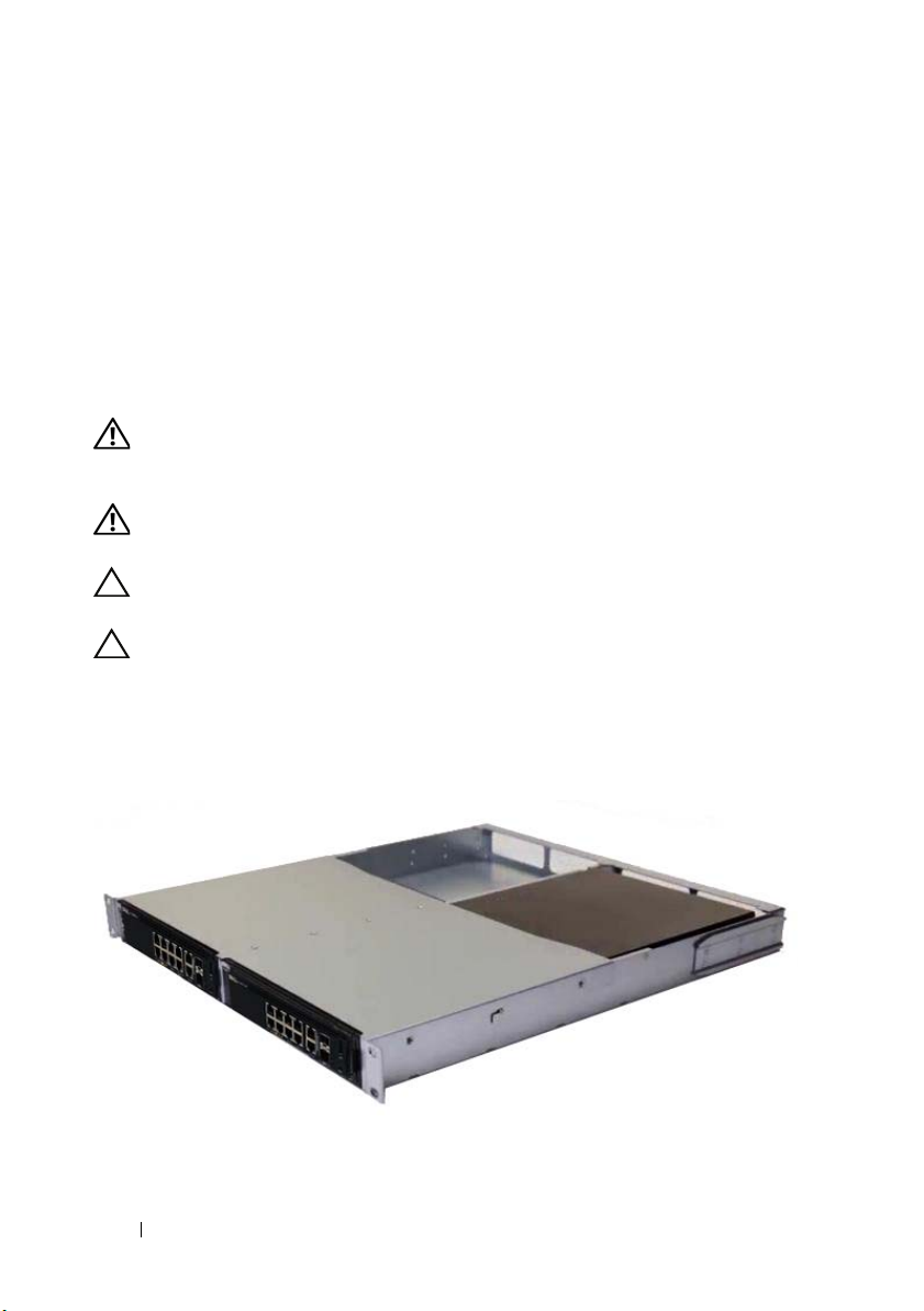
Mounting an N1108T-ON/N1108P-ON Switch
Using Dell Tandem Tray
The AC power connector is on the rear panel.
WARNING: Read the safety information in the
as well as the safety information for other switches that connect to or support the
switch.
WARNING: Do not use rack mounting kits to suspend the switch from under a
table or desk, or attach it to a wall.
CAUTION: Disconnect all cables from the switch before continuing. Remove all
self-adhesive pads from the underside of the switch, if they have been attached.
CAUTION: When mounting multiple switches into a rack, mount the switches
from the bottom up.
1
Secure the N1108T-ON/N1108P-ON switch in the Dell Tandem Tray Kit
as shown in Figure 1-1.
Figure 1-1. Dell Tandem Tray Kit
Safety and Regulatory Information
2
Insert the switch into the 48.26 cm (19 inch) rack, ensuring that the rack
mounting holes on the kit line up to the mounting holes in the rack.
8 Getting Started Guide
3
Secure the kit to the rack with either the rack bolts or cage nuts and cagenut bolts with washers (depending on the kind of rack you have). Fasten
the bolts on the bottom before fastening the bolts on the top.
Mounting an N1108T-ON/N1108P-ON/N1108EPON on a Two-Post Rack Using Large L-brackets
NOTE: The AC power connector is on the rear panel of the N1108T-ON/N1108P-ON
switches. The DC power connector for the N1108EP-ON is at the center of the rear
panel.
NOTE: The N1108EP-ON switch uses an external power adaptor. There is no mounting kit
available for the N1108EP-ON external power adaptor. When installing the
N1108EP-ON, place the external power adaptor away from the switch.
CAUTION: As the N1108EP-ON is a fanless switch, do not place the external power
adaptor on top of the switch to avoid overheating.
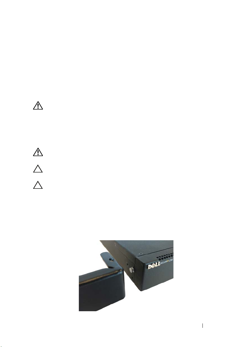
1
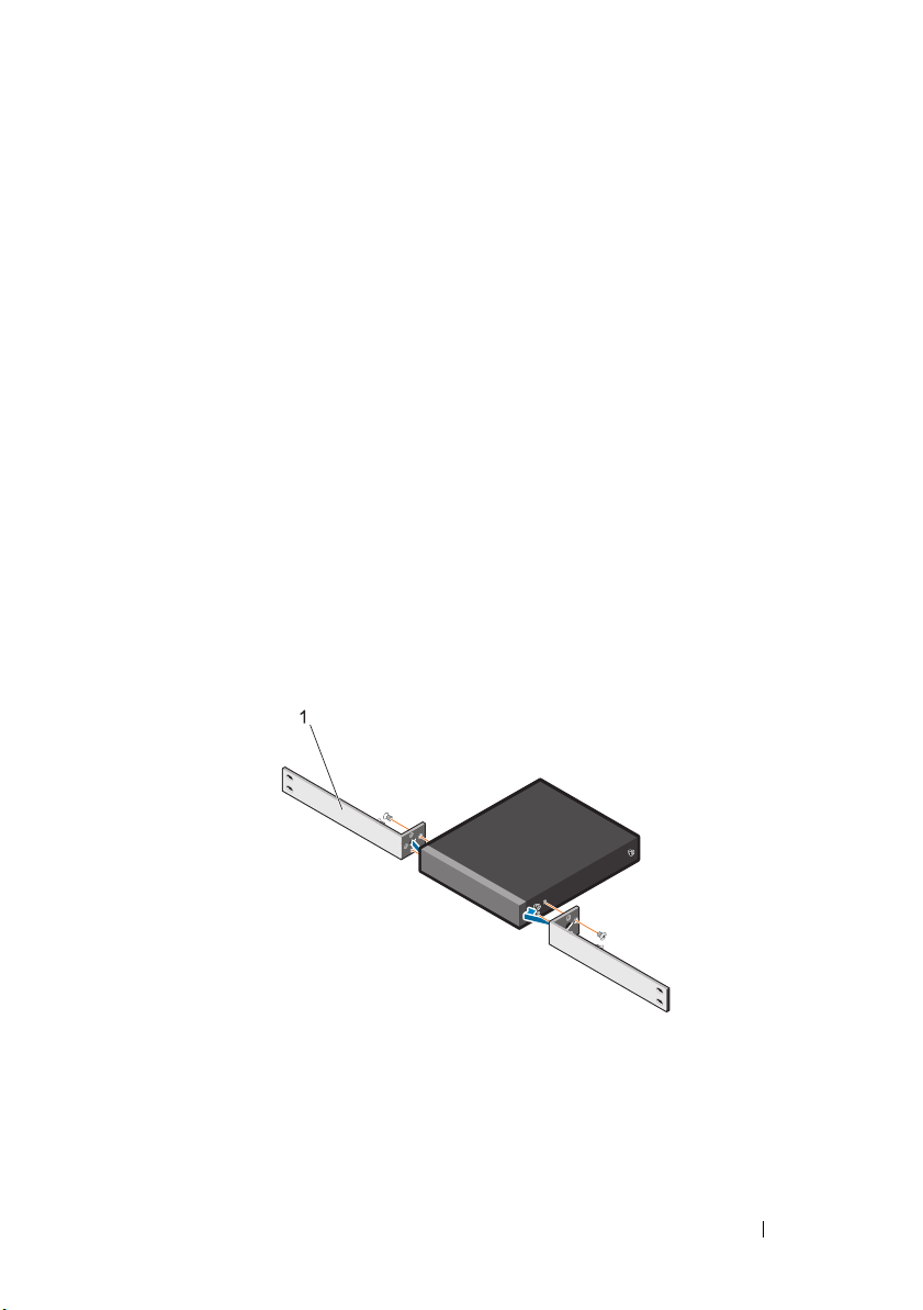
Place the supplied rack-mounting bracket on one side of the switch
making sure that the mounting holes on the switch line up to the
mounting holes on the rack mounting bracket. See item 1 in Figure 1-2.
Figure 1-2. Installing Using Large L-bracket Kit
2
Insert the supplied screws into the rack mounting holes and tighten with a
screwdriver.
3
Repeat the process on the other side of the switch.
Getting Started Guide 9
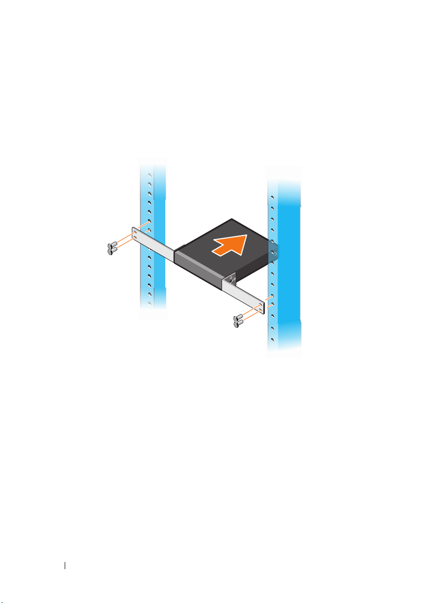
4
Insert the switch and rail assembly into the rack from the front of the rack.
Make sure that the rack-mounting holes on the switch line up to the
mounting holes on the rack.
5
Secure the switch to the rack with the rack screws. Fasten the lower pair of
screws before the upper pair of screws. See Figure 1-3.
Figure 1-3. Install on a Two-post Rack with L-Bracket
Mounting all N11xx-ON Switches on a Wall
1
Make sure that the mounting location meets the following requirements:
• The surface of the wall can support the switch.
• The location is ventilated to prevent heat buildup.
2
Place the supplied wall-mounting bracket on one side of the switch,
verifying that the mounting holes on the switch line up to the mounting
holes on the wall-mounting bracket.
3
Insert the supplied screws into the wall-mounting bracket holes and
tighten with a screwdriver. See Figure 1-4.
10 Getting Started Guide
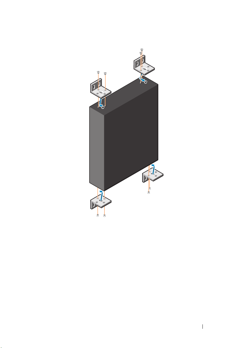
Figure 1-4. Inserting Mounting Brackets
4
Repeat the process for the wall-mounting bracket on the other side of the
switch.
5
Place the switch on the wall in the location where the switch is being
installed.
6
Mark the locations on the wall where the screws to hold the switch must be
prepared.
7
On the marked locations, drill the holes and place all the eight supplied
anchors in the holes.
8
Insert the supplied screws into the wall-mounting bracket holes and
tighten them with a screwdriver. See Figure 1-5.
Getting Started Guide 11
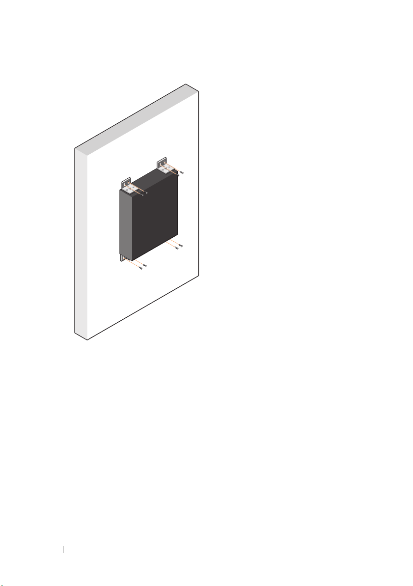
Figure 1-5. Mounting on a Wall
12 Getting Started Guide
N1124T-ON/N1124P-ON/N1148T-ON/
N1148P-ON Installation
Rack Mounting an N1124T-ON/N1124P-ON/
N1148T-ON/ N1148P-ON Switch
WARNING: Read the safety information in the
as well as the safety information for other switches that connect to or support the
switch.
The AC power connector is on the rear panel of the switch.
Safety and Regulatory Information
Installing in a Rack
WARNING: Do not use rack mounting kits to suspend the switch from under a
table or desk, or attach it to a wall.
CAUTION: Disconnect all cables from the switch before continuing. Remove all
self-adhesive pads from the underside of the switch, if they have been attached.
CAUTION: When mounting multiple switches into a rack, mount the switches
from the bottom up.
1
Place the supplied rack-mounting bracket on one side of the switch,
ensuring that the mounting holes on the switch line up to the mounting
holes in the rack-mounting bracket. Figure 1-6 illustrates where to mount
the brackets.
Figure 1-6. Attaching the Brackets
Getting Started Guide 13

2
Insert the supplied bolts into the rack-mounting holes and tighten with a
screwdriver.
3
Repeat the process for the rack-mounting bracket on the other side of the
switch.
4
Insert the switch into the 48.26 cm (19 inch) rack, ensuring that the rackmounting holes on the bracket line up with the mounting holes in the
rack.
5
Secure the bracket to the rack with either the rack bolts or cage nuts and
cage-nut bolts with washers (depending on the kind of rack you have).
Fasten the bolts on the bottom before fastening the bolts on the top.
CAUTION: Make sure that the supplied rack bolts fit the pre-threaded holes in the
rack.
NOTE: Make sure that the ventilation holes are not obstructed.
Installing as a Free-standing Switch
NOTE: Dell strongly recommends mounting the switch in a rack.
Install the switch on a flat surface if you are not installing it in a rack. The
surface must be able to support the weight of the switch and the switch
cables. The switch is supplied with four self-adhesive rubber pads.
1
Attach the self-adhesive rubber pads on each location marked on the
bottom of the switch.
2
Set the switch on a flat surface, and make sure that it has proper
ventilation by leaving 5 cm (2 inches) on each side and 13 cm (5 inches) at
the back.
Stacking Multiple N1124T-ON/N1124P-ON/
N1148T-ON/ N1148P-ON Switches
You can stack N1124T-ON/N1124P-ON/N1148T-ON/ N1148P-ON switches
up to four switches high using 10G SFP+ ports on the front of the switch.
The ports must be configured to support stacking. When multiple switches
are connected together through the stack ports, they operate as a single unit
with up to 208 front-panel ports. The stack operates and is managed as a
single entity. Refer to the User Configuration Guide and the CLI Reference
Guide for more information.
14 Getting Started Guide
Starting and Configuring the
N1100-ON Series Switch
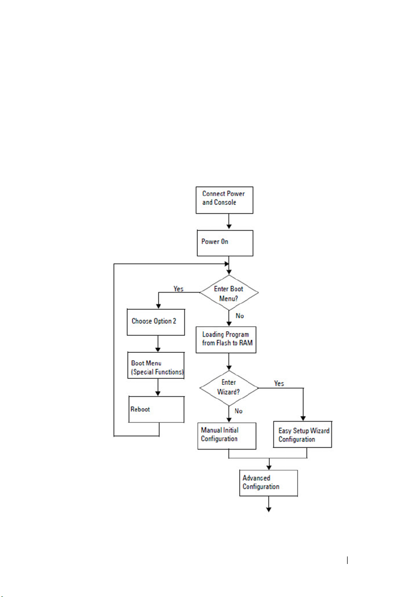
The following flow chart provides an overview of the steps you use to perform
the initial configuration after the switch is unpacked and mounted.
Figure 1-7. Installation and Configuration Flow Chart
Getting Started Guide 15

Connecting an N1100-ON Series Switch to a
Terminal
After completing all external connections, configure the switch by connecting
it to a terminal.
NOTE: Read the Release Notes for this product before proceeding. You can
download the Release Notes from the Dell Support website at dell.com/support.
NOTE: Dell recommends that you obtain the most recent version of the user
documentation from the Dell Support website at dell.com/support.
To monitor and configure the switch via the USB console, use the console
port on the front panel of the switch to connect it to a computer running
VT100 terminal emulation software using the supplied USB cable. It may be
necessary to download and install a driver on first use of the USB cable.
The following equipment is required to use the console port:
• VT100-compatible computer with a USB port running VT100 terminal
emulation software,
• The supplied USB cable with a type B USB connector for the console port
and USB connector for the host PC.
Perform the following tasks to connect a terminal to the switch console port:
1
Connect the USB type B connector on the supplied switch and connect
the other end to a computer running VT100 terminal emulation software.
2
Configure the terminal emulation software as follows:
a
Select the appropriate serial port (for example, COM 1) to connect to
the console.
b
Set the data rate to 115,200 baud.
c
Set the data format to 8 data bits, 1 stop bit, and no parity.
d
Set the flow control to none.
e
Set the terminal emulation mode to
f
Select Terminal keys for Function, Arrow, and Ctrl keys. Make sure
that the setting is for Terminal keys (not Microsoft Windows keys).
3
Connect the USB type B connector on the cable directly to the switch
console port. The Dell Networking console port is located on the right side
of the front panel and is labeled with a
such as HyperTerminal® and a USB driver.
VT100
.
|O|O|
symbol.
16 Getting Started Guide

NOTE: Console access to the stack manager is available from any console
port via the local CLI. Only one USB console session at a time is supported.
Connecting an N1100-ON Series Switch to a
Power Source
CAUTION: Read the safety information in the
manual as well as the safety information for other switches that connect to or
support the switch.
The N1108T-ON and N1108P-ON models have one internal power supply.
The
power receptacle is on the rear panel. N1108EP-ON uses an external DC
power adaptor. The external DC power adaptor
Safety and Regulatory Information
AC and DC Power Connection
1
Make sure that the switch console port is connected to a PC running a
VT100 terminal emulator via the USB to USB Type B cable.
2
Using a 5-foot (1.5 m) standard power cable with safety ground connected,
connect the power cable to the AC main receptacle located on the rear
panel.
The PoE model switches have a heavy-duty power cable with a notched
connector for the switch power receptacle. Use of this type of cable is
mandatory for PoE-capable switches.
3
Connect the power cable to a grounded AC outlet.
Getting Started Guide 17

Booting the N1100-ON Series Switch
When the power is turned on with the local terminal already connected, the
switch goes through a power-on self-test (POST). POST runs every time the
switch is initialized and checks hardware components to determine if the
switch is fully operational before completely booting. If POST detects a
critical problem, the program flow stops. If POST passes successfully, valid
firmware is loaded into RAM. POST messages are displayed on the terminal
and indicate test success or failure. The boot process runs for approximately
60 seconds.
You can invoke the Boot menu after the first part of the POST is completed.
From the Boot menu, you can perform configuration tasks such as resetting
the system to factory defaults, activating the backup image, or recovering a
password. For more information about the Boot menu functions, refer to the
CLI Reference Guide.
18 Getting Started Guide
 Loading...