

Dell PowerEdge C6320p User Manual

Dell PowerEdge C6320p
Owner's Manual
Reg ula tor y M ode l: B08 S S eries
Reg ula tor y T ype : B 08S 004
Oct obe r 2 020
Rev . A 03

Notes, cautions, and warnings
NOTE: A NOTE indicates important information that helps you make better use of your product.
CAUTION: A CAUTION indicates either potential damage to hardware or loss of data and tells you how to avoid
the problem.
WARNING: A WARNING indicates a potential for property damage, personal injury, or death.
© 2017 - 2018 Dell Inc. or its subsidiaries. All rights reserved . D ell , E MC, and other trademarks are trademarks of Dell Inc. or its subsidi ari es.
Other trademarks may be trademarks of their respective owners.

Contents
Chapter 1: Dell PowerEdge C6320p overview.................................................................................8
Supported configurations for PowerEdge C6300 enclosure and C6320p sled....................................................8
Front panel...........................................................................................................................................................................12
Front panel features of the PowerEdge 6300 enclosure with PowerEdge C6320p sleds.........................12
Back panel............................................................................................................................................................................15
Back panel features of the PowerEdge 6300 enclosure with PowerEdge C6320p sleds..........................15
Diagnostic indicators......................................................................................................................................................... 17
Hard drive indicator patterns.....................................................................................................................................17
Network ports indicator codes................................................................................................................................. 18
Power Supply Unit indicator codes.......................................................................................................................... 19
Power and system board indicator codes............................................................................................................. 22
iDRAC heart beat LED................................................................................................................................................ 22
Configuration restrictions of the Intel Xeon Phi 72XX or Phi 72XXF processor................................................23
Sled to hard drive connection layout............................................................................................................................23
Locating your system Service Tag................................................................................................................................ 23
Chapter 2: Documentation resources...........................................................................................26
Chapter 3: Technical specifications............................................................................................. 29
Chassis dimensions........................................................................................................................................................... 29
Chassis weight................................................................................................................................................................... 30
Processor specifications..................................................................................................................................................30
PSU specifications............................................................................................................................................................ 30
System battery specifications ................................................................................................................................. 31
Memory specifications .....................................................................................................................................................31
Hard drives and storage specifications.........................................................................................................................31
Internal SD card slot..........................................................................................................................................................31
Ports and connectors specifications............................................................................................................................. 31
USB ports.......................................................................................................................................................................31
NIC ports....................................................................................................................................................................... 32
VGA ports......................................................................................................................................................................32
Video specifications.......................................................................................................................................................... 32
Environmental specifications..........................................................................................................................................32
Chapter 4: Initial system setup and configuration........................................................................34
Accessing system features during startup..................................................................................................................34
Setting up your system.................................................................................................................................................... 34
iDRAC configuration......................................................................................................................................................... 34
Options to set up iDRAC IP address....................................................................................................................... 34
Options to install the operating system.......................................................................................................................35
Methods to download firmware and drivers.........................................................................................................35
Chapter 5: Pre-operating system management applications........................................................ 37
Options to manage the pre-operating system applications.................................................................................... 37
Contents 3

System Setup..................................................................................................................................................................... 37
Viewing System Setup............................................................................................................................................... 38
System Setup details.................................................................................................................................................. 38
System BIOS.................................................................................................................................................................38
iDRAC Settings utility.................................................................................................................................................60
Device Settings.............................................................................................................................................................61
Dell Lifecycle Controller...................................................................................................................................................62
Embedded systems management............................................................................................................................62
Boot Manager.....................................................................................................................................................................62
Viewing Boot Manager............................................................................................................................................... 62
Boot Manager main menu......................................................................................................................................... 63
PXE boot............................................................................................................................................................................. 63
Chapter 6: Updating the Fan Control Board firmware.................................................................. 64
Fan control board firmware............................................................................................................................................ 64
Updating the fan control board firmware using Racadm...................................................................................64
Checking the FCB firmware version.......................................................................................................................65
Chassis type sticky bits................................................................................................................................................... 66
Setting chassis type sticky bits for the PowerEdge C6320p sleds................................................................ 66
Checking the chassis type sticky bits for the PowerEdge C6320p sled....................................................... 66
Chapter 7: Prerequisites for installing and removing components................................................67
Safety instructions............................................................................................................................................................ 67
Before working inside your system............................................................................................................................... 67
After working inside your system.................................................................................................................................. 68
Recommended tools......................................................................................................................................................... 68
Chapter 8: Installing and removing sled components................................................................... 69
Inside the system.............................................................................................................................................................. 69
PowerEdge C6320p sled..................................................................................................................................................71
Removing a sled ...........................................................................................................................................................71
Installing a sled ............................................................................................................................................................72
Air shroud............................................................................................................................................................................ 73
Removing the air shroud ........................................................................................................................................... 73
Installing the air shroud ............................................................................................................................................. 74
System memory................................................................................................................................................................. 75
Memory slot features ................................................................................................................................................ 75
Supported memory module configuration ............................................................................................................ 75
Removing the memory modules ..............................................................................................................................76
Installing the memory modules................................................................................................................................. 77
1.8-inch Solid State Drive................................................................................................................................................ 78
Removing the 1.8-inch solid state drive................................................................................................................. 79
Installing the 1.8-inch solid state drive................................................................................................................... 80
Removing the 1.8-inch solid state drive carrier.................................................................................................... 81
Installing the 1.8-inch solid state drive carrier......................................................................................................83
SATA cable removal and installation for the sled...................................................................................................... 84
Removing the SATA cable from the sled...............................................................................................................84
Removing the SSD SATA cable from the sled..................................................................................................... 85
Installing the SSD SATA cable into the sled..........................................................................................................87
4
Contents

Installing the SATA cable into the sled...................................................................................................................88
Processor and heat sink module.................................................................................................................................... 89
Removing the fabric cable from the processor................................................................................................... 90
Connecting the fabric cable to the processor...................................................................................................... 91
Removing the processor and heat sink module................................................................................................... 92
Installing the processor and heat sink module......................................................................................................94
Removing the fabric processor from the processor heat sink module.......................................................... 96
Installing the fabric processor into the processor heat sink module...............................................................97
Removing the non fabric processor from the processor heat sink module.................................................100
Installing the non fabric processor into the processor and heat sink module.............................................102
Expansion card assembly and expansion card .........................................................................................................105
PCIe slot priority ....................................................................................................................................................... 105
Removing the expansion card riser assembly..................................................................................................... 106
Installing the expansion card riser assembly........................................................................................................107
Removing an expansion card.................................................................................................................................. 109
Installing an expansion card..................................................................................................................................... 112
Removing the riser card............................................................................................................................................115
Installing the riser card.............................................................................................................................................. 116
Removing the cables from the fabric carrier card.............................................................................................. 117
Connecting the cables to the fabric carrier card................................................................................................ 118
Mezzanine cards and mezzanine bridge card...........................................................................................................120
Removing a mezzanine card................................................................................................................................... 120
Installing a mezzanine card......................................................................................................................................122
Removing the mezzanine card bridge board ......................................................................................................124
Installing the mezzanine card bridge board......................................................................................................... 125
Removing a mezzanine card filler bracket........................................................................................................... 126
Installing a mezzanine card filler bracket............................................................................................................. 128
System battery ................................................................................................................................................................129
Removing the system battery - option A............................................................................................................. 129
Installing the system battery - option A............................................................................................................... 130
Removing the system battery - option B..............................................................................................................131
Installing the system battery- option B................................................................................................................ 132
Trusted Platform Module...............................................................................................................................................132
Installing the Trusted Platform Module................................................................................................................ 133
Initializing the Trusted Platform Module.............................................................................................................. 134
System board....................................................................................................................................................................134
Removing a system board ...................................................................................................................................... 134
Installing a system board .........................................................................................................................................136
SAS connector protector............................................................................................................................................... 137
Removing the SAS connector protector.............................................................................................................. 137
Installing the SAS connector protector................................................................................................................ 138
Chapter 9: Installing and removing enclosure components......................................................... 140
2.5-inch hard drive or solid state drive...................................................................................................................... 140
Removing a hard drive carrier.................................................................................................................................140
Installing a hard drive carrier....................................................................................................................................141
Removing a hard drive from a hard drive carrier............................................................................................... 142
Installing a hard drive into a hard drive carrier................................................................................................... 143
Power supply units.......................................................................................................................................................... 144
Removing a power supply unit................................................................................................................................145
Contents
5

Installing a power supply unit..................................................................................................................................146
System cover....................................................................................................................................................................148
Removing the system cover....................................................................................................................................148
Installing the system cover...................................................................................................................................... 149
Cooling fans...................................................................................................................................................................... 150
Removing a cooling fan............................................................................................................................................ 150
Installing a cooling fan............................................................................................................................................... 151
Removing a cooling fan cage.................................................................................................................................. 152
Installing a cooling fan cage.................................................................................................................................... 153
Power distribution boards..............................................................................................................................................154
Removing the power distribution boards ............................................................................................................ 154
Installing the power distribution boards............................................................................................................... 157
Cable routing and connectors of the power distribution boards ................................................................... 161
Midplanes...........................................................................................................................................................................163
Removing the midplanes.......................................................................................................................................... 163
Installing the midplanes.............................................................................................................................................167
Cable routing–midplane to the hard drive backplane ...................................................................................... 168
Hard drive backplanes.................................................................................................................................................... 170
Removing the hard drive backplane...................................................................................................................... 170
Installing the hard drive backplane........................................................................................................................ 172
Control panel.....................................................................................................................................................................175
Removing the control panel.....................................................................................................................................175
Installing the control panel....................................................................................................................................... 177
Thermal sensor board..................................................................................................................................................... 179
Removing the sensor board cover......................................................................................................................... 179
Installing the sensor board cover........................................................................................................................... 180
Removing the sensor board .................................................................................................................................... 181
Installing the sensor board....................................................................................................................................... 182
Cable routing for sensor board and control panel for 2.5-inch hard drive system....................................183
Chapter 10: Using system diagnostics........................................................................................ 185
Dell Embedded System Diagnostics............................................................................................................................ 185
When to use the Embedded System Diagnostics.............................................................................................. 185
Running the Embedded System Diagnostics from Boot Manager.................................................................185
Running the Embedded System Diagnostics from the Dell Lifecycle Controller........................................185
System diagnostic controls..................................................................................................................................... 186
Chapter 11: Jumpers and connectors ......................................................................................... 187
PowerEdge C6320p system board connectors........................................................................................................187
Jumper settings on the PowerEdge C6320p system board................................................................................. 188
Chapter 12: Troubleshooting your system.................................................................................. 189
Troubleshooting system startup failure......................................................................................................................189
Troubleshooting external connections....................................................................................................................... 189
Troubleshooting the video subsystem........................................................................................................................190
Troubleshooting a USB device..................................................................................................................................... 190
Troubleshooting a serial input and output device.....................................................................................................191
Troubleshooting a NIC.....................................................................................................................................................191
Troubleshooting a wet system..................................................................................................................................... 192
6
Contents

Troubleshooting a damaged system............................................................................................................................192
Troubleshooting the system battery...........................................................................................................................193
Troubleshooting power supply units........................................................................................................................... 194
Troubleshooting power source problems.............................................................................................................194
Power supply unit problems.................................................................................................................................... 194
Troubleshooting cooling problems...............................................................................................................................195
Troubleshooting cooling fans........................................................................................................................................195
Troubleshooting system memory.................................................................................................................................196
Troubleshooting a micro SD card.................................................................................................................................197
Troubleshooting a drive or SSD....................................................................................................................................197
Troubleshooting expansion cards................................................................................................................................ 198
Troubleshooting processors.......................................................................................................................................... 199
System messages............................................................................................................................................................ 199
Warning messages.....................................................................................................................................................199
Diagnostic messages.................................................................................................................................................199
Alert messages........................................................................................................................................................... 199
Chapter 13: Getting help........................................................................................................... 200
Contacting Dell EMC......................................................................................................................................................200
Documentation feedback..............................................................................................................................................200
Accessing system information by using QRL........................................................................................................... 200
Quick Resource Locator for the PowerEdge C6320p system........................................................................201
Contents
7

Dell PowerEdge C6320p overview
The Dell PowerEdge C6300 is an ultra-dense 2U enclosure that can support up to four independent single-socket (1S) sleds
connected to a direct backplane that supports twenty four 2.5-inch hard drives and two hot plug power supply units. Each
PowerEdge C6320p sled has the following features:
● Each sled features an Intel Xeon Phi 72XX or 72XXF processor with 64, 68, or 72 cores
● Each processor features a 16 GB MCDIMM
● Support for up to six DDR4 LRDIMM or RDIMM memory modules
● Each sled supports six 2.5-inch hard drives or Solid State Drives.
● Intel C612 chipset for I/O connectivity
● Each sled has the integrated iDRAC8 express systems management with a dedicated RJ45 management port
● Each sled has an embedded 1 Gigabit Ethernet controller (RJ45)
● Optional integrated Mellanox ConnectX-4 VPI EDR / 100 GbE Port
WARNING: Sleds using the Intel Xeon Phi 72XX and Phi 72XXF processors must not be installed in the same
enclosure.
NOTE: Mixing the PowerEdge C6320 and PowerEdge C6320p sleds in the same PowerEdge C6300 enclosure is not
supported.
Topics:
1
• Supported configurations for PowerEdge C6300 enclosure and C6320p sled
• Front panel
• Back panel
• Diagnostic indicators
• Configuration restrictions of the Intel Xeon Phi 72XX or Phi 72XXF processor
• Sled to hard drive connection layout
• Locating your system Service Tag
Supported configurations for PowerEdge C6300 enclosure and C6320p sled
The Dell PowerEdge C6300 enclosure supports the following configurations:
8 Dell PowerEdge C6320p overview
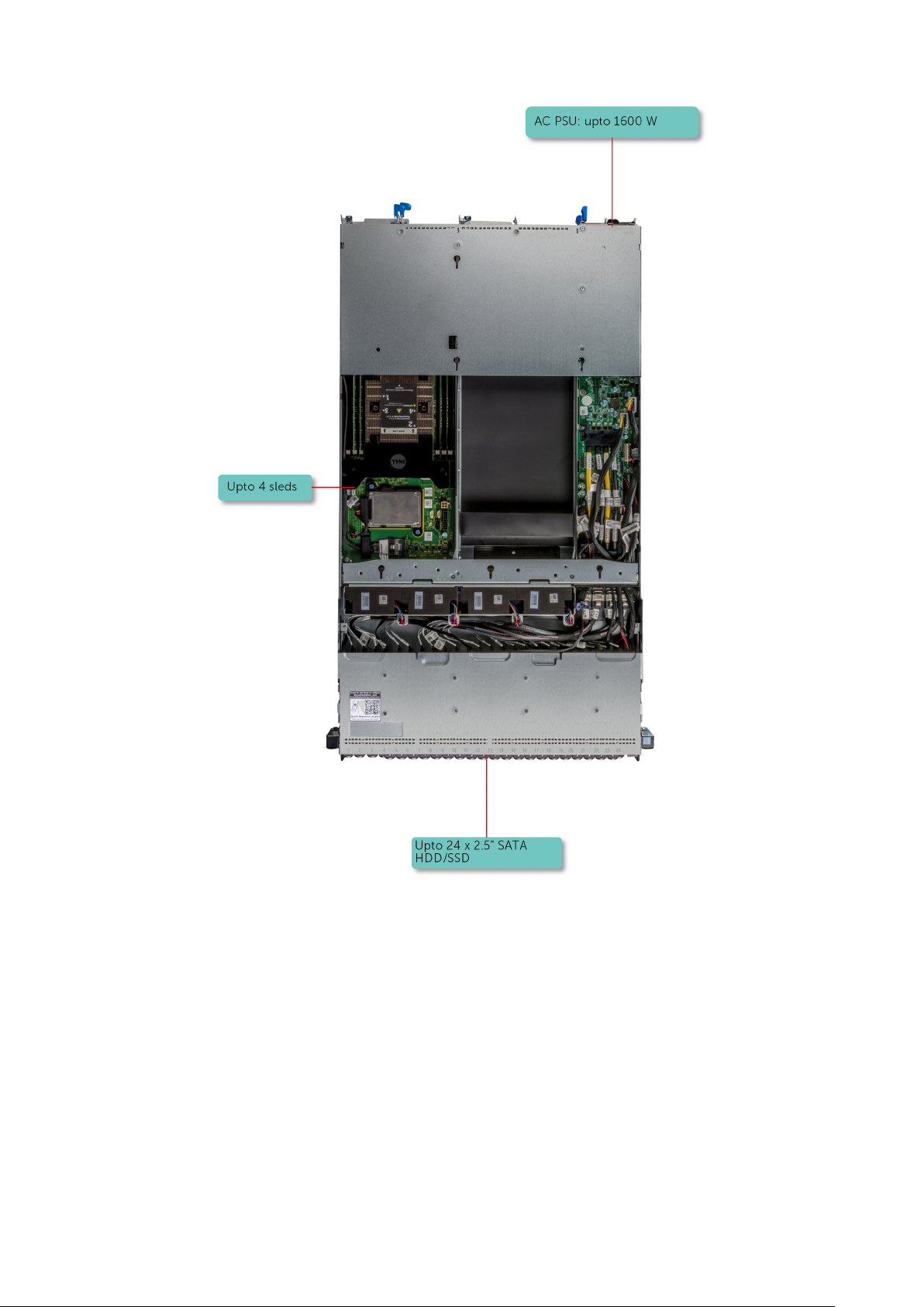
Figure 1. Supported configurations for C6300
The Dell PowerEdge C6320p sled supports the following configurations:
Dell PowerEdge C6320p overview
9
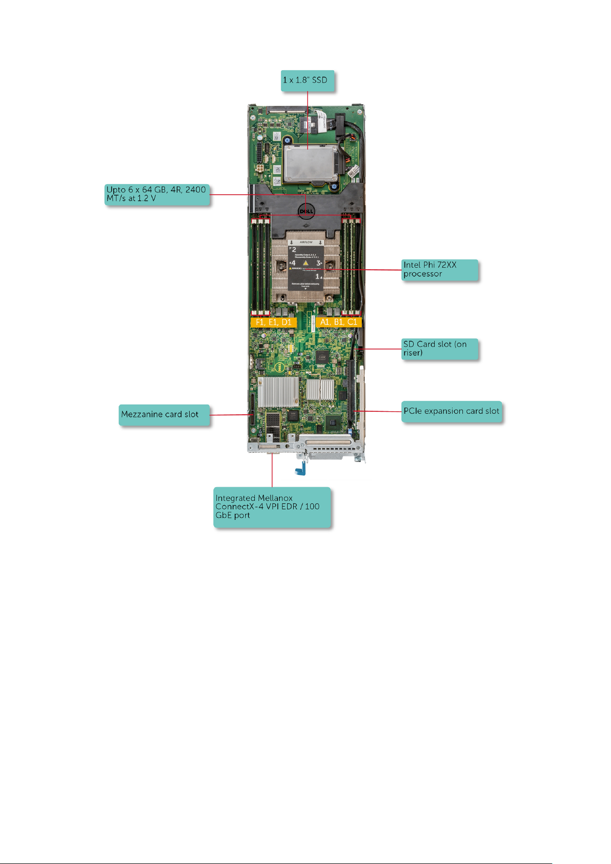
Figure 2. Supported configuration for the C6320p sled with an Intel Phi 72xx processor
10
Dell PowerEdge C6320p overview
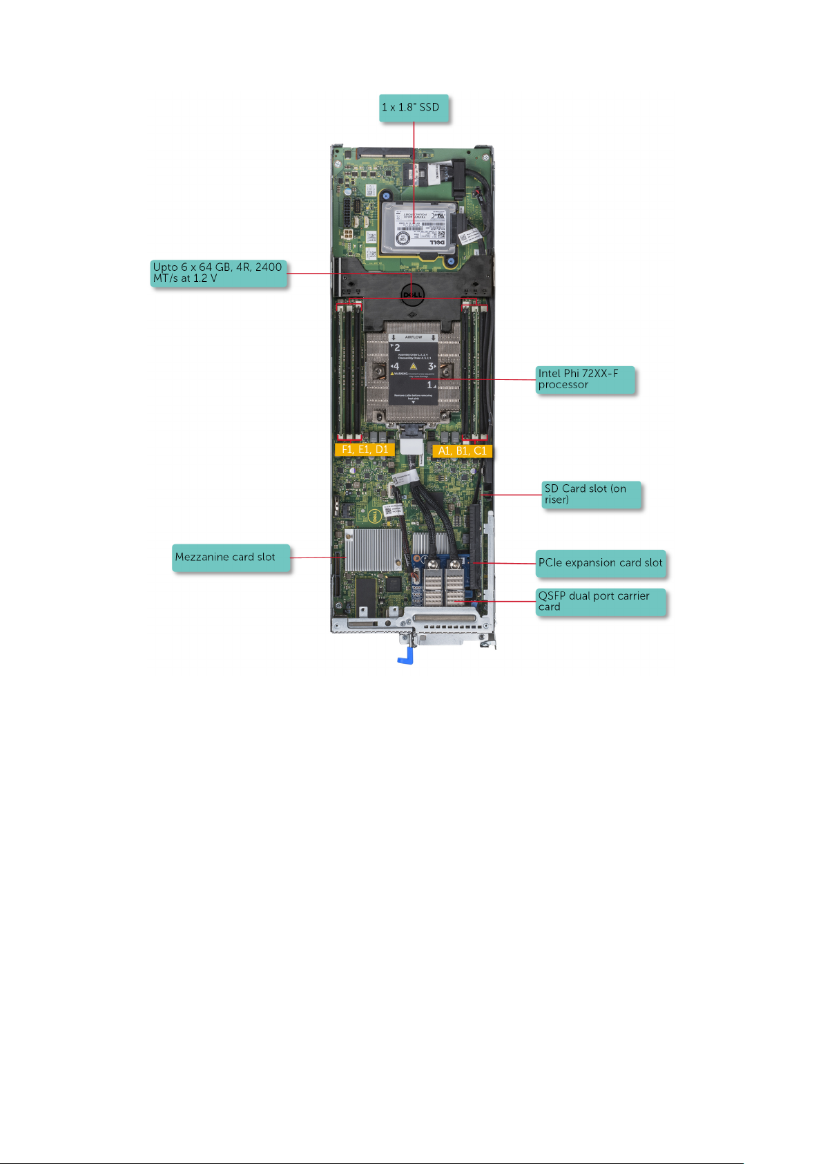
Figure 3. Supported configuration for the C6320p sled with an Intel Phi 72xx-F processor
Dell PowerEdge C6320p overview
11
Front panel
The front panel provides access to the features available on the front of the server, such as the power button, and the system
identification button. The hot swappable hard drives are accessible from the front panel.
Front panel features of the PowerEdge 6300 enclosure with PowerEdge C6320p sleds
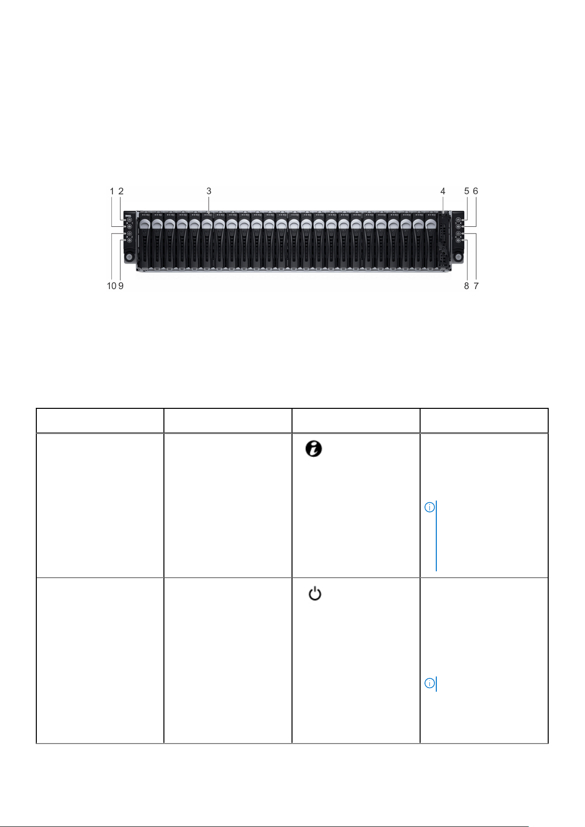
Figure 4. Front panel features and indicators
1. system identification indicator for sled 1 2. power button for sled 1
3. hard drives (24) 4. ambient temperature sensor cover
5. power button for sled 3 6. system identification indicator for sled 3
7. power button for sled 4 8. system identification indicator for sled 4
9. system identification indicator for sled 2 10. power button for sled 2
Table 1. Front panel features and indicators
Item Indicator, Button, or
Connector
1 System identification indicator
or button for sled 1
2 Power-on indicator or system
state indicator or power
button for sled 1
Icon Description
Press the system ID button:
● To locate a particular sled
within the enclosure.
● To turn the system ID on
or off.
NOTE: If the sled stops
responding during POST,
press and hold the sled ID
button (for more than five
seconds) to enter the
BIOS progress mode.
Press the power button to
turn the sled on or off. The
indicator on the button
indicates if the sled is on or
off.
The power-on indicator turns
Amber when a critical system
event occurs.
12 Dell PowerEdge C6320p overview
NOTE:
To gracefully shut down an
ACPI-compliant operating
system, press the power
button.
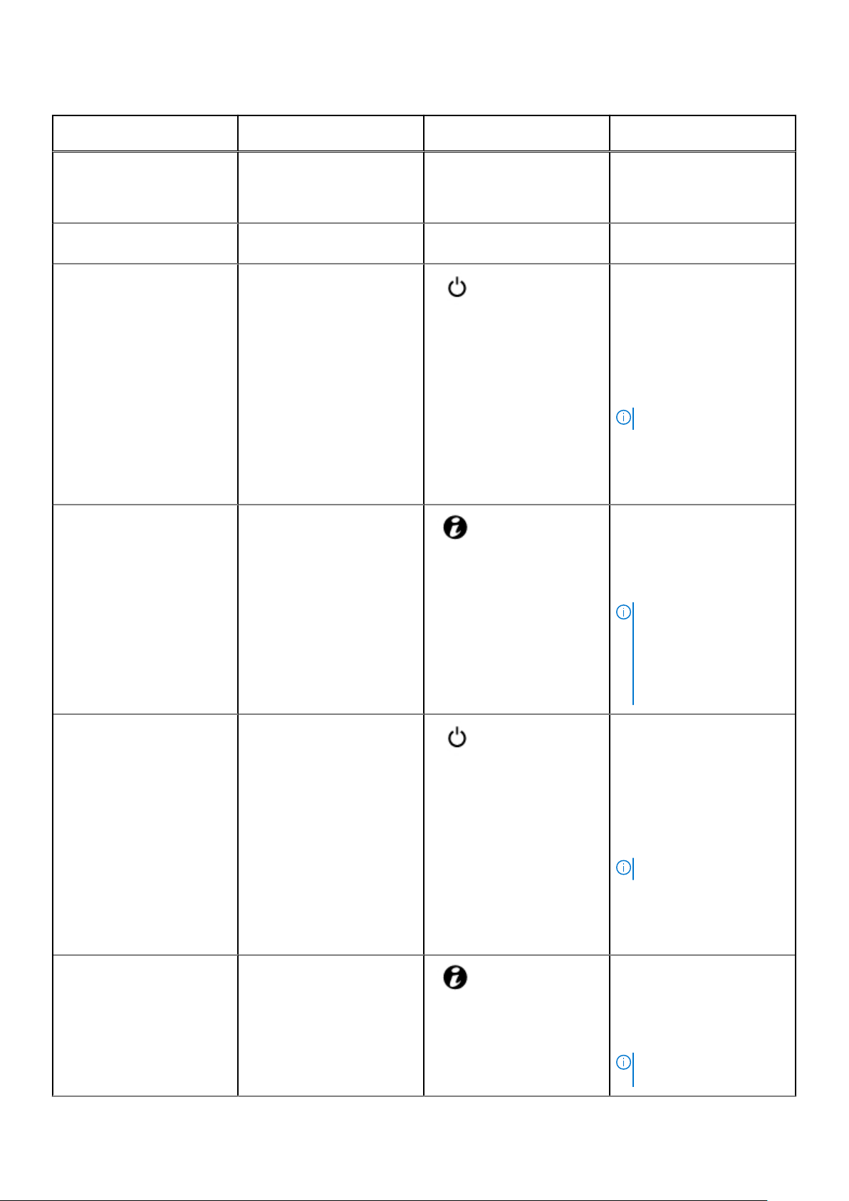
Table 1. Front panel features and indicators (continued)
Item Indicator, Button, or
Connector
3 Hard drives Up to 24, hot-swappable, 2.5-
4 Ambient temperature sensor
cover
5 Power-on indicator or system
state indicator or power
button for sled 3
6 System identification indicator
or button for sled 3
Icon Description
inch hard drives. Six hard
drives are allocated to each
sled in the enclosure.
Ambient temperature sensor
is located behind this cover.
Press the power button to
turn the sled on or off. The
indicator on the button
indicates if the sled is on or
off.
The power-on indicator turns
Amber when a critical system
event occurs.
NOTE:
To gracefully shut down an
ACPI-compliant operating
system, press the power
button.
Press the system ID button:
● To locate a particular sled
within the enclosure.
● To turn the system ID on
or off.
NOTE: If the sled stops
responding during POST,
press and hold the system
ID button (for more than
five seconds) to enter the
BIOS progress mode.
7 Power-on indicator or system
state indicator or power
button for sled 4
8 System identification indicator
or button for sled 4
Press the power button to
turn the sled on or off. The
indicator on the button
indicates if the sled is on or
off.
The power-on indicator turns
Amber when a critical system
event occurs.
NOTE:
To gracefully shut down an
ACPI-compliant operating
system, press the power
button.
Press the system ID button:
● To locate a particular sled
within the enclosure.
● To turn the system ID on
or off.
NOTE: If the sled stops
responding during POST,
Dell PowerEdge C6320p overview 13
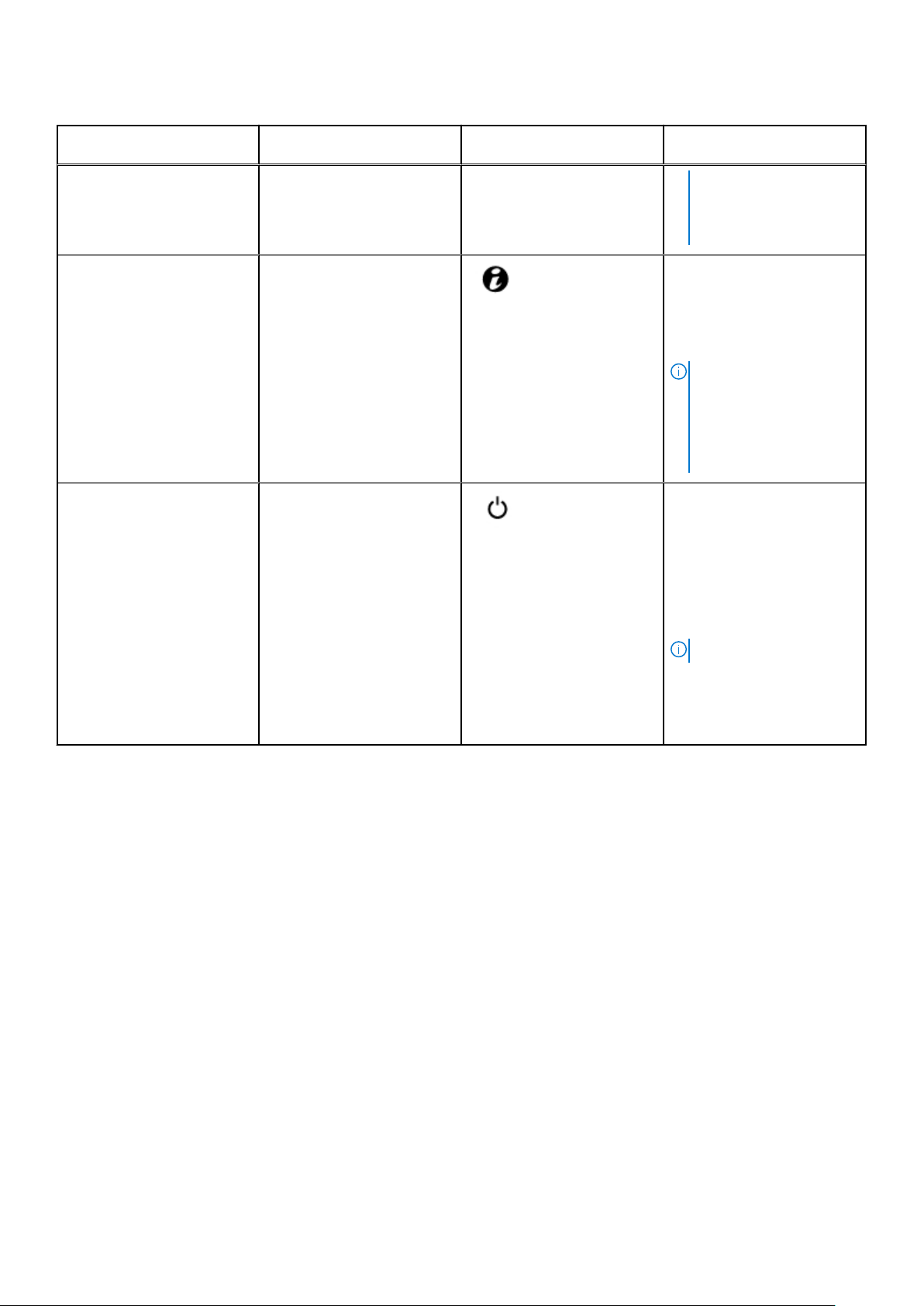
Table 1. Front panel features and indicators (continued)
Item Indicator, Button, or
Connector
9 System identification indicator
or button for sled 2
10 Power-on indicator or system
state indicator or power
button for sled 2
Icon Description
press and hold the system
ID button (for more than
five seconds) to enter the
BIOS progress mode.
Press the system ID button:
● To locate a particular sled
within the enclosure.
● To turn the system ID on
or off.
NOTE: If the sled stops
responding during POST,
press and hold the system
ID button (for more than
five seconds) to enter the
BIOS progress mode.
Press the power button to
turn the sled on or off. The
indicator on the button
indicates if the sled is on or
off.
The power-on indicator turns
Amber when a critical system
event occurs.
NOTE:
To gracefully shut down an
ACPI-compliant operating
system, press the power
button.
14 Dell PowerEdge C6320p overview
Back panel
The back panel provides access to the features available on the back of the server, such as the system identification button,
power supply sockets, iDRAC connectivity port, NIC ports, and USB and the VGA port. Most of the expansion card ports can be
accessed from the back panel.
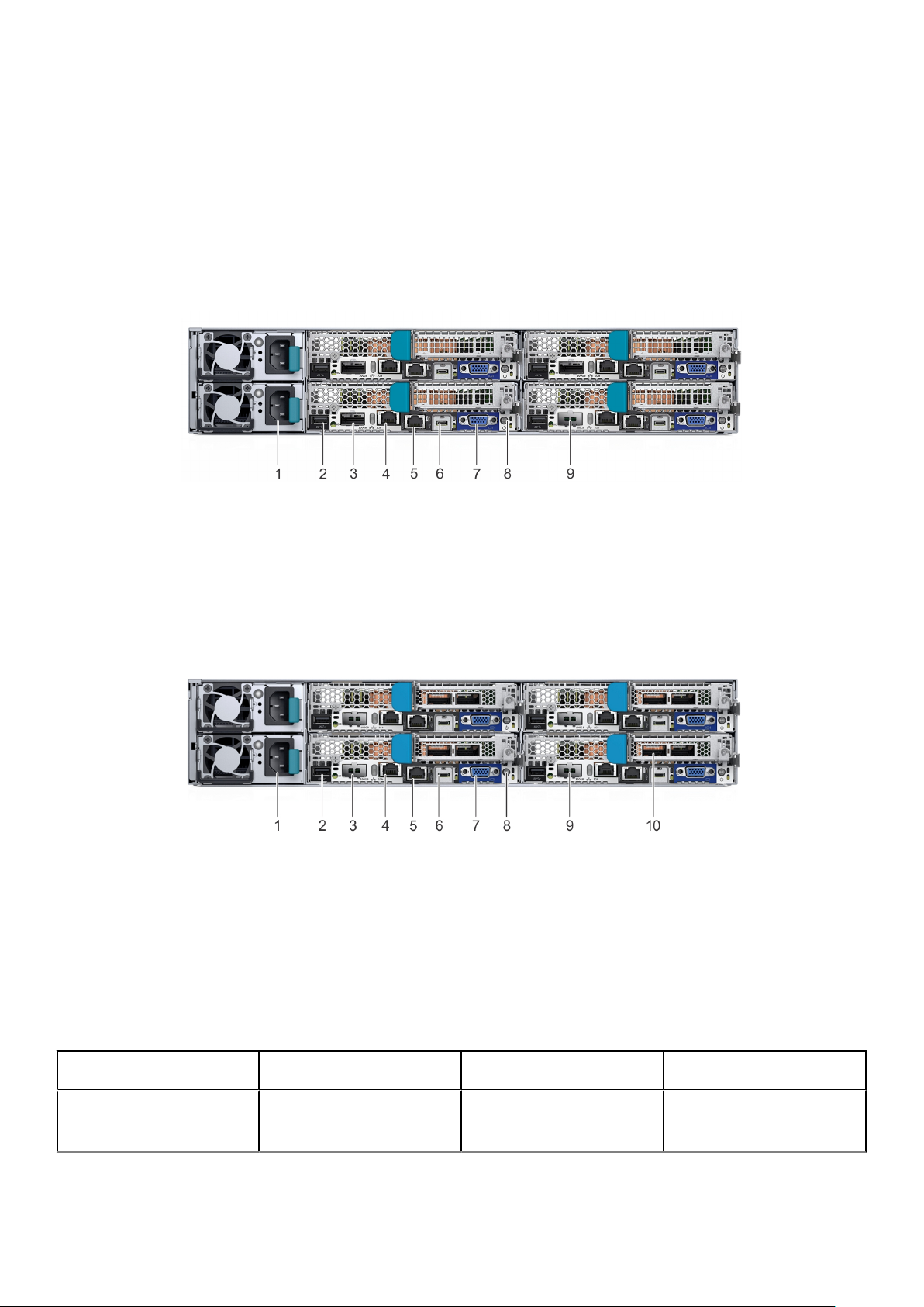
Back panel features of the PowerEdge 6300 enclosure with PowerEdge C6320p sleds
Figure 5. Back panel features and indicators Intel Phi 72xx processor based sleds
1. Power supply unit (2) 2. Universal Serial Bus port
3. Integrated Quad Small Form-factor Pluggable port 4. Ethernet port
5. iDRAC Enterprise management port 6. Micro Universal Serial Bus port
7. VGA port 8. Power button/power-on indicator
9. Sled without the integrated Quad Small Form-factor
Pluggable port
Figure 6. Back panel features and indicators Intel Phi 72xx-F processor based sleds
Power supply unit (2) 2. Universal Serial Bus port
1.
3. Sled without the integrated Quad Small Form-factor
Pluggable port
5. iDRAC Enterprise management port 6. Micro Universal Serial Bus port
7. VGA port 8. Power button/power-on indicator
9. Sled without the integrated Quad Small Form-factor
Pluggable port
4. Ethernet port
10. Sled with the Quad Small Form-factor Pluggable carrier card
Table 2. Back panel features and indicators
Item Indicator, Button, or
Connector
1 Power supply unit (2)
Icon Description
Up to two hot swappable
1400 W or 1600 W AC Power
supply unit (PSU).
Dell PowerEdge C6320p overview 15
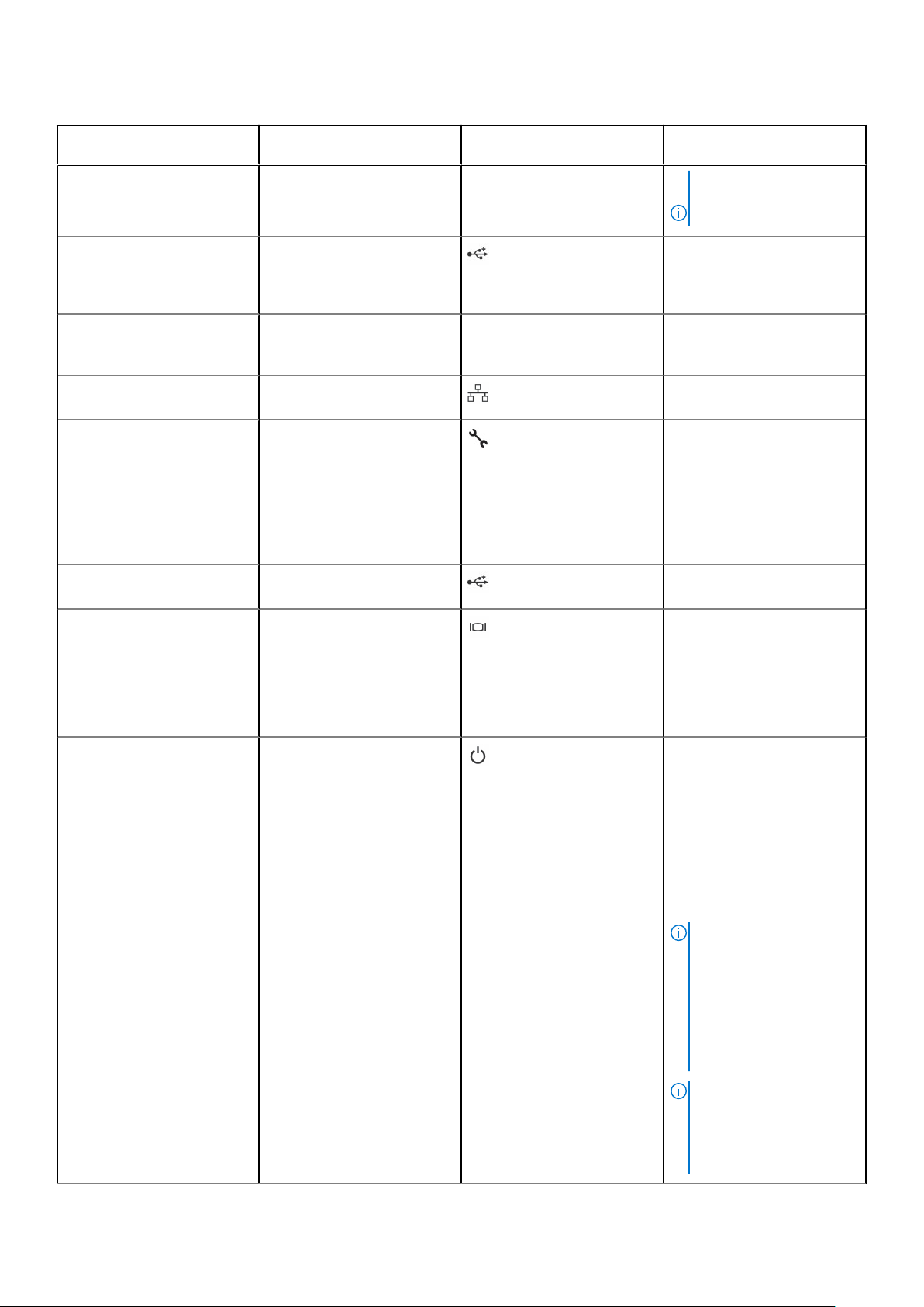
Table 2. Back panel features and indicators (continued)
Item Indicator, Button, or
Connector
2 Universal Serial Bus (USB
port)
3 Quad Small Form-factor
Pluggable (QSFP port)
4 Ethernet port Single Port 1Gb LOM Ethernet
5 iDRAC Enterprise
management port
6 Micro Universal Serial Bus
(USB port)
Icon Description
NOTE: PSU’s with
different wattages cannot
be mixed.
Use the USB 3.0 port to
connect USB devices to the
system. This port is a 9-pin,
USB 3.0 compliant port.
Mellanox ConnectX-4 VPI
EDR / 100 GbE Embedded
Port (optional)
port
Use the iDRAC8 Enterprise
management port to remotely
access iDRAC. For more
information, see the
Integrated Dell Remote
Access Controller User’s
Guide at Dell.com/
idracmanuals.
Use the port to connect the
system to a host.
7 VGA port Use the video/VGA port to
connect a display to the
system. For more information
about the supported
video/VGA port, see the
Technical specifications
section.
8 Power button/power-on
indicator
The power-on indicator glows
green when the system power
is on.
The power-on indicator turns
amber when there a critical
system event occurs.
The power button controls
the PSU output to the system
board.
NOTE: When turning on
the system, the video
monitor can take from
several seconds to over
two minutes to display an
image, on the basis of the
disk space available in the
system.
16 Dell PowerEdge C6320p overview
NOTE: On ACPI-
compliant operating
systems, turning off the
system by using the
power button causes the
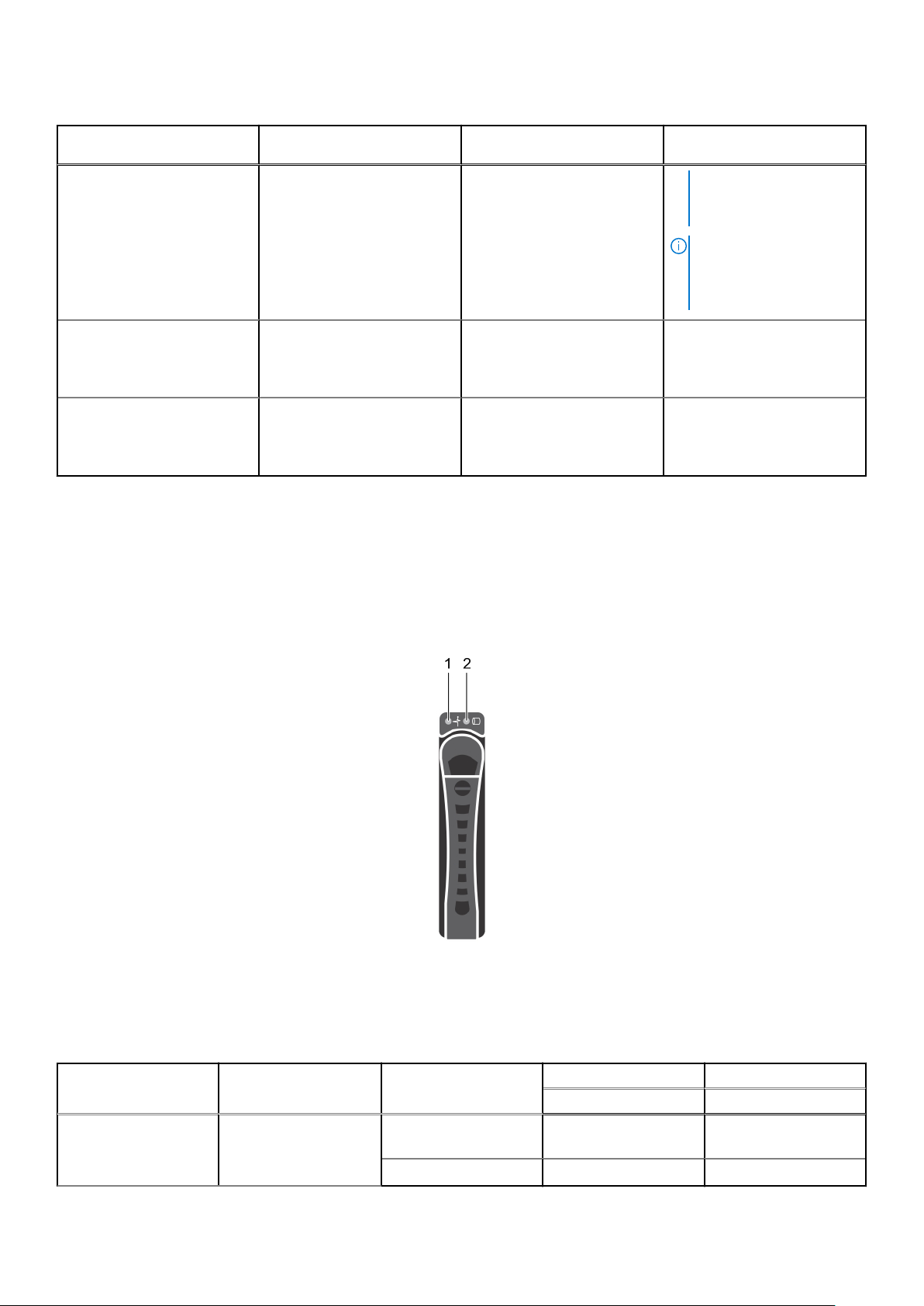
Table 2. Back panel features and indicators (continued)
Item Indicator, Button, or
Connector
9 Sled without the integrated
Quad Small Form-factor
Pluggable port
10 Sled with the Quad Small
Form-factor Pluggable carrier
card
Icon Description
Diagnostic indicators
The diagnostic indicators on the system indicate operation and error status.
system to perform a
graceful shutdown before
the system is turned off.
NOTE: To force an
ungraceful shutdown,
press and hold the power
button for five seconds.
Sled without the (optional)
Mellanox ConnectX-4 VPI
EDR / 100 GbE Embedded
Port.
Sled with the Quad Small
Form-factor Pluggable carrier
card and the fabric based
processor.
Hard drive indicator patterns
Figure 7. Hard drive front view
1. hard drive status indicator (green and amber)
2. hard drive activity indicator (green)
Table 3. Hard drive indicator patterns
Controller Hard drive type Function Activity LED Status LED
Green Green
Onboard Controller SATA3 Drive on-line Off/Blinking when
active
Fail Off On
Dell PowerEdge C6320p overview 17
On
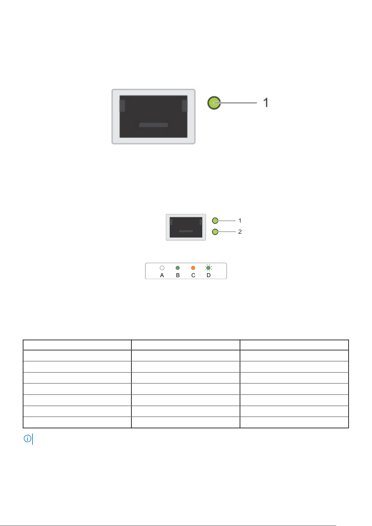
Network ports indicator codes
Figure 8. LAN indicators on the QSFP carrier card
Figure 9. LAN indicators
1. Link indicator
2. Activity indicator
Table 4. QSFP port indicator codes
Connection State QSFP Upper green LED QSFP Lower green LED
No link / Not Connected Off Off
InfiniBand Physical Link - No Logical Link Green Off
InfiniBand Logical Link – No Traffic Green Green
InfiniBand Logical Link - Traffic Green Blink
InfiniBand Physical Link Issue Blink Green
Ethernet Link – No Traffic Green Green
Ethernet - Traffic Green Blink
NOTE: The LED blink speed varies according to the traffic bandwidth.
18 Dell PowerEdge C6320p overview
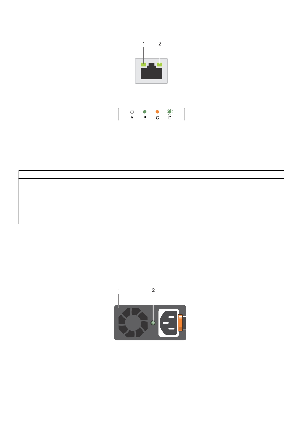
Figure 10. Ethernet port indicator codes
1. speed indicator
2. link and activity indicator
Table 5. Ethernet port indicator codes
Convention Status Condition
A Link and activity indicators are off The NIC is not connected to the network.
B Link indicator is green The NIC is connected to a valid network at its
maximum port speed (1 Gbps).
C Link indicator is amber The NIC is connected to a valid network at less
than its maximum port speed.
D Activity indicator is flashing green Network data is being sent or received.
Power Supply Unit indicator codes
Each AC power supply unit (PSU) has an illuminated translucent handle that indicates whether power is present or whether a
power fault has occurred.
1400 W AC or HVDC Power supply units
Figure 11. Power supply unit (PSU) status indicators
1. PSU
2. PSU status indicator LED
Dell PowerEdge C6320p overview
19
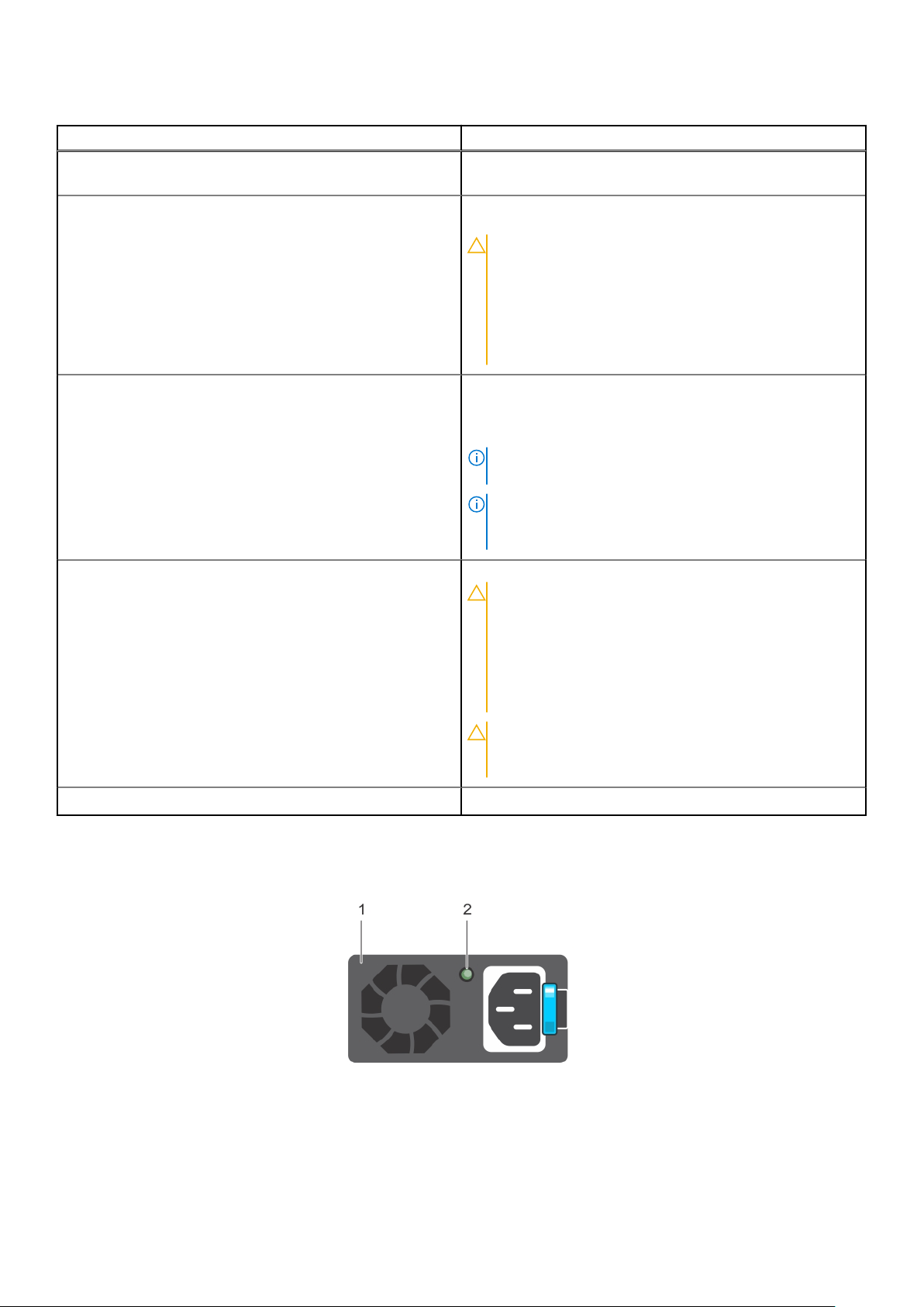
Table 6. 1400 W AC or HVDC PSU indicators
Power Indicator Pattern Condition
Green A valid power source is connected to the PSU and the PSU is
operational.
Flashing green When the PSU firmware is being updated, the PSU LED
flashes green.
CAUTION: Do not disconnect the power cord or
unplug the PSU when updating firmware. If firmware
update is interrupted, the PSUs will not function.
You must roll back the PSU firmware by using Dell
Lifecycle Controller. For more information, see Dell
Lifecycle Controller User’s Guide at Dell.com/
idracmanuals.
Flashing green and turns off When hot-adding a PSU, the PSU LED flashes green five
times at 4 Hz rate and turns off. This indicates that there is a
PSU mismatch with respect to efficiency, feature set, health
status, and supported voltage.
NOTE: Ensure that both the PSUs are of the same
capacity.
NOTE: Mixing PSUs from previous generations of Dell
PowerEdge servers can result in a PSU mismatch
condition and failure to turn the system on.
Flashing amber Indicates a problem with the PSU.
CAUTION: When correcting a PSU mismatch, replace
only the PSU with the flashing indicator. Swapping
the other PSU to make a matched pair can result in
an error condition and unexpected system shutdown.
To change from a High Output configuration to a
Low Output configuration or vice versa, you must
turn off the system.
CAUTION: If two PSUs are used, they must be of the
same type and have the same maximum output
power.
Not lit Power is not connected.
1600 W AC or HVDC Power supply unit
Figure 12. Power supply unit (PSU) status indicator
1. PSU
2. Power indicator
20
Dell PowerEdge C6320p overview

Table 7. 1600 W AC or HVDC PSU indicators
Convention Power Indicator Pattern Description
Green A valid power source is connected to the
A
B Flashing green When the firmware of the PSU is being
PSU and the PSU is operational.
updated, the PSU LED flashes green.
CAUTION: Do not disconnect the
power cord or unplug the PSU
when updating firmware. If
firmware update is interrupted,
the PSUs will not function. You
must roll back the PSU firmware
by using Dell Lifecycle Controller.
See
Dell Lifecycle Controller
User’s Guide
idracmanuals.
CAUTION: Do not disconnect the
power cord or unplug the PSU
when updating firmware. If
firmware update is interrupted,
the PSUs will not function.
NOTE: Ensure that both the PSUs
are of the same capacity.
at Dell.com/
NOTE: Mixing PSUs from previous
generations of Dell PowerEdge
servers will result in a PSU mismatch
condition or failure to turn the
system on.
C Flashes green and turns off When hot-adding a PSU, the PSU LED
flashes green five times at 4 Hz rate and
turns off. This indicates that there is a
PSU mismatch with respect to
efficiency, feature set, health status, and
supported voltage.
D Flashing amber Indicates a problem with the PSU.
CAUTION: When correcting a
PSU mismatch, replace only the
PSU with the flashing indicator.
Swapping the other PSU to make
a matched pair can result in an
error condition and unexpected
system shutdown. To change
from a High Output configuration
to a Low Output configuration or
vice versa, you must turn off the
system.
NOTE: AC PSUs support both 220 V
and 110 V input voltages. When two
identical PSUs receive different input
voltages, they can output different
wattages, and trigger a mismatch.
CAUTION: If two PSUs are used,
they must be of the same type
Dell PowerEdge C6320p overview 21
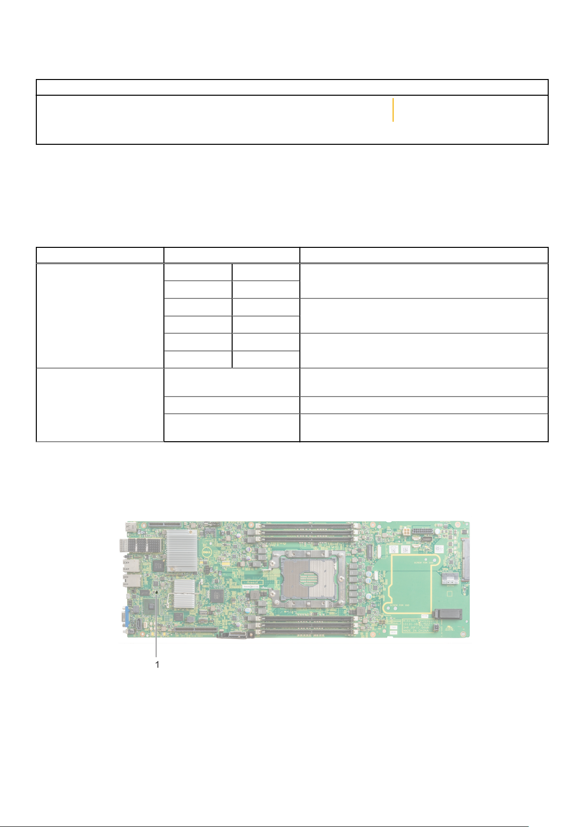
Table 7. 1600 W AC or HVDC PSU indicators (continued)
Convention Power Indicator Pattern Description
and have the same maximum
output power.
E Not lit Power is not connected.
Power and system board indicator codes
The LEDs on the enclosure front panel and back panel display status codes during system startup and operation. For location of
the LEDs on the front panel, see the Front panel features and indicators section. For location of the LEDs on the back panel, see
the Back panel features and indicators section.
Table 8. Status indicator codes
Component Indicator Condition
Power-on indicator (A bi-color
LED on power button)
System identification indicator Steady blue IPMI using Chassis Identify Command On or ID Button Press
Green Solid Power On (S0)
Amber Off
Green Off iDRAC critical condition event in Power Off mode (S4/S5)
Amber Blinking
Green Off iDRAC critical condition event in Power On mode (S0)
Amber On
ID On
Blinking blue Only IPMI using Chassis Identify Command Blink On
Off IPMI using Chassis Identify Command Off or ID Button
Press ID Off
iDRAC heart beat LED
The system board provides iDRAC heart beat LED (CR17) for iDRAC debugging. The iDRAC heart beat LED is green. When the
power is connected, the LED is on. When iDRAC firmware is ready, the iDRAC heart beat LED blinks.
Figure 13. iDRAC heart beat LED
1. iDRAC heart beat LED
22
Dell PowerEdge C6320p overview
Configuration restrictions of the Intel Xeon Phi 72XX or Phi 72XXF processor
WARNING: Sleds using the Intel Xeon Phi 72XX and Phi 72XXF processors must not be installed in the same
enclosure.
CAUTION: Certain system hardware configurations may require reductions in the upper temperature limits.
NOTE: System performance may be impacted when operating above 35°C (95°F) or with a faulty fan.
Table 9. Configuration restrictions of the Intel Xeon Phi 72XX or Phi 72XXF processor
Processor wattage Processor model Applicable restrictions
Phi 7210
215 W
230 Phi 7210F
245 Phi 7290
260 Phi 7290F
Phi 7230
Phi 7250
Phi 7230F
Phi 7250F
10°C (50°F) to 35°C (95°F) with a
maximum temperature gradation of 10
degree C per hour
Ambient temperature limited to 23°C
(73.4°F)
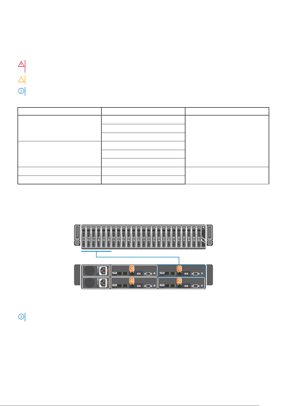
Sled to hard drive connection layout
The connection of the twenty four 2.5–inch hot swappable hard drives to the four sleds is shown as follows:
Figure 14. Sled to hard drive connection layout
NOTE: The warranty of the hard drives are linked to the Service Tag of the corresponding sled.
Locating your system Service Tag
Your system is identified by a unique Express Service Code and Service Tag number. The Express Service Code is found on the
front of the system and Service Tag is found on the front of the system. Alternatively, the information may be on a sticker on
the chassis of the system. This information is used by Dell to route support calls to the appropriate personnel. The Service Tag
locations on the chassis are as follows:
Dell PowerEdge C6320p overview
23
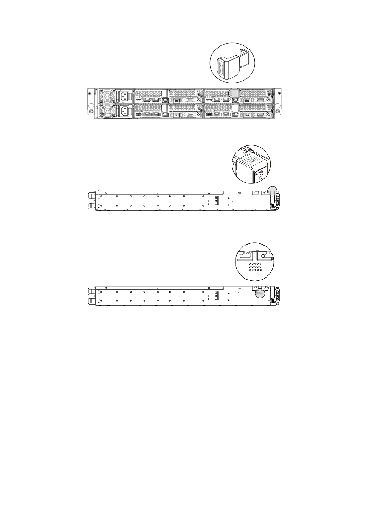
Figure 15. Service Tag location
Figure 16. Service Tag location on the left front panel
Figure 17. Service Tag location on the chassis
24
Dell PowerEdge C6320p overview
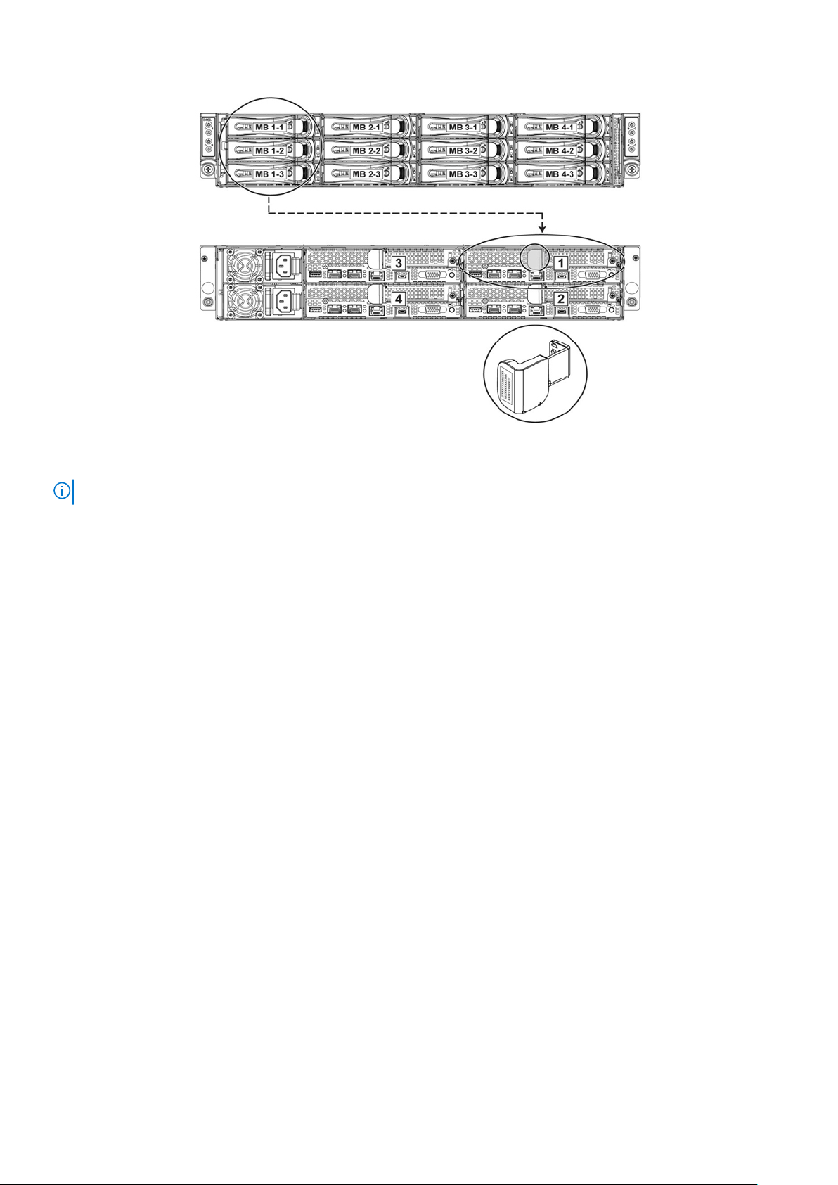
Figure 18. Service Tag linkage
NOTE: Hard drives that are under warranty are linked to the appropriate Service Tag of the node.
Dell PowerEdge C6320p overview 25
Documentation resources
This section provides information about the documentation resources for your system.
To view the document that is listed in the documentation resources table:
● From the Dell EMC support site:
1. Click the documentation link that is provided in the Location column in the table.
2. Click the required product or product version.
NOTE: To locate the product name and model, see the front of your system.
3. On the Product Support page, click Manuals & documents.
● Using search engines:
○ Type the name and version of the document in the search box.
Table 10. Additional documentation resources for your system
Task Document Location
2
Setting up your
system
Configuring your
system
For information about installing the
system into a rack, see the Rack
documentation included with the
Getting Started With Your System
document that is shipped with
your system.
For information about the iDRAC
features, configuring and logging
in to iDRAC, and managing your
system remotely, see the
Integrated Dell Remote Access
Controller User's Guide.
For information about
understanding Remote Access
Controller Admin (RACADM)
subcommands and supported
RACADM interfaces, see the
RACADM CLI Guide for iDRAC.
For information about Redfish and
its protocol, supported schema,
and Redfish Eventing are
implemented in iDRAC, see the
Redfish API Guide.
For information about iDRAC
property database group and
object descriptions, see the
Attribute Registry Guide.
www.dell.com/poweredgemanuals
www.dell.com/poweredgemanuals
For information about earlier
versions of the iDRAC documents,
see the iDRAC documentation.
To identify the version of iDRAC
available on your system, on the
iDRAC web interface, click ? >
About.
26 Documentation resources
www.dell.com/idracmanuals

Table 10. Additional documentation resources for your system (continued)
Task Document Location
Managing your
system
For information about installing the
operating system, see the
operating system documentation.
For information about updating
drivers and firmware, see the
Methods to download firmware
and drivers section in this
document.
For information about systems
management software offered by
Dell, see the Dell OpenManage
Systems Management Overview
Guide.
For information about setting up,
using, and troubleshooting
OpenManage, see the Dell
OpenManage Server Administrator
User’s Guide.
For information about installing,
using, and troubleshooting Dell
OpenManage Essentials, see the
Dell OpenManage Essentials User’s
Guide.
For information about installing,
using, and troubleshooting Dell
OpenManage Enterprise, see the
Dell OpenManage Enterprise
User’s Guide.
www.dell.com/
operatingsystemmanuals
www.dell.com/support/drivers
www.dell.com/poweredgemanuals
www.dell.com/
openmanagemanuals >
OpenManage Server Administrator
www.dell.com/
openmanagemanuals >
OpenManage Essentials
www.dell.com/
openmanagemanuals >
OpenManage Enterprise
Understanding event
and error messages
Fan Control Board
firmware update and
For information about installing
and using Dell SupportAssist, see
the Dell EMC SupportAssist
Enterprise User’s Guide.
For information about partner
programs enterprise systems
management, see the
OpenManage Connections
Enterprise Systems Management
documents.
Working with the Dell PowerEdge
RAID controllers
For information about the event
and error messages that are
generated by the system firmware
and agents that monitor system
components, see the Error Code
Lookup.
For information about updating the
Fan Control Board firmware and
setting the chassis type to
https://www.dell.com/
serviceabilitytools
www.dell.com/
openmanagemanuals
For information about
understanding the features of the
Dell PowerEdge RAID controllers
(PERC), Software RAID
controllers, or BOSS card and
deploying the cards, see the
Storage controller documentation.
www.dell.com/qrl
www.dell.com/poweredgemanuals
www.dell.com/
storagecontrollermanuals
Documentation resources 27

Table 10. Additional documentation resources for your system (continued)
Task Document Location
Set Chassis Type
procedure
Troubleshooting your
system
accommodate either PowerEdge
C6320 or PowerEdge C6320p
sleds in the PowerEdge C6300
enclosure, see the Fan Control
Board firmware update and Set
Chassis Type procedure section in
this document.
For information about identifying
and troubleshooting the
PowerEdge server issues, see the
Server Troubleshooting Guide.
www.dell.com/poweredgemanuals
28 Documentation resources
Technical specifications
The technical and environmental specifications of your system are outlined in this section.
Topics:
• Chassis dimensions
• Chassis weight
• Processor specifications
• PSU specifications
• System battery specifications
• Memory specifications
• Hard drives and storage specifications
• Internal SD card slot
• Ports and connectors specifications
• Video specifications
• Environmental specifications
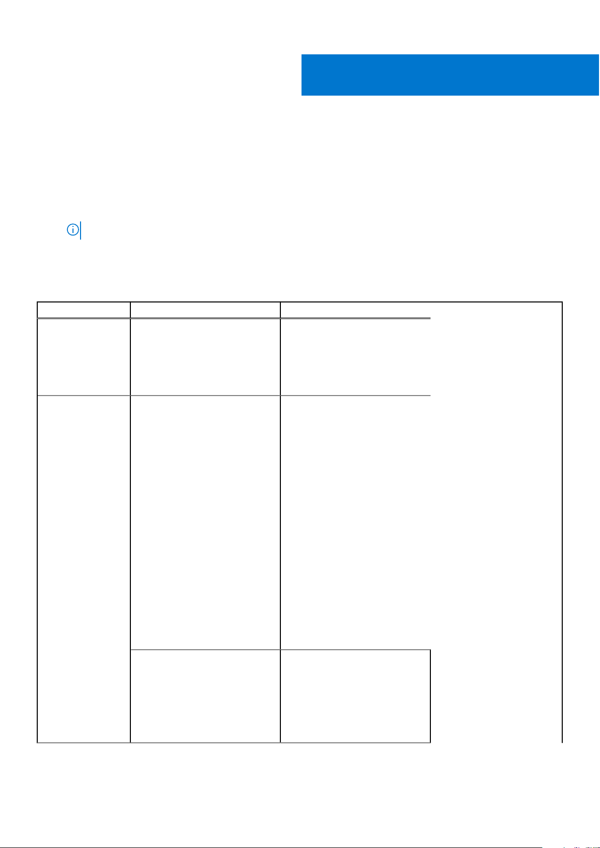
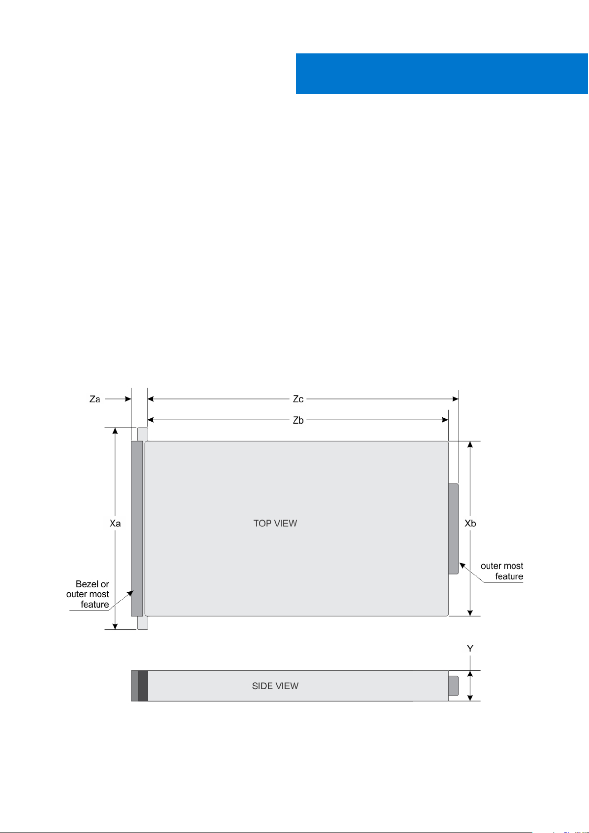
Chassis dimensions
3
Figure 19. Chassis dimensions of PowerEdge C6300 enclosure
Technical specifications 29

Table 11. Dimensions of the Dell PowerEdge C6300 enclosure
Xa Xb Y Za (with
bezel)
482.3 mm 448.0 mm 86.8 mm N/A 41.4 mm 762.1 mm 795.9 mm
Za (without
bezel)
Zb Zc
Chassis weight
Table 12. Chassis weight
System Maximum weight (with all sleds and hard drives/SSDs)
PowerEdge C6300 enclosure and
the PowerEdge C6320p sleds
36.5 Kg (80.4 lb)
Processor specifications
The Dell PowerEdge C6320p supports an Intel Xeon Phi 72XXF or 72XX product family processor in four independent sleds.
PSU specifications
Dell PowerEdge C6300 enclosure supports up to two AC or HVDC power supply units (PSUs). Dell PowerEdge C6320p does not
support a mixed installation of 1400 W and 1600 W PSUs. The 1400 W and 1600 W PSUs are hot swappable and support hot
swap in any condition if the system has the power throttling feature enabled.
Table 13. PSU specifications
PSU Heat dissipation
1400 W AC
1400 W HVDC
(China only)
1600 W AC
1600 W HVDC – 240 V DC 10 A
(maximum)
5220.763 BTU/hr
5966.586 BTU/hr
Frequency Voltage Maximum input
50/60 Hz 200-240 V AC 9 A Initial inrush current
– 240 V DC 9 A
50/60 Hz 100-120 V AC
200-240 V AC
current
12 A
10 A
Maximum inrush
current (peak)
cannot exceed 55 A
(peak).
Secondary inrush
current cannot
exceed 25 A (peak).
Initial inrush current
and secondary
inrush current
cannot exceed 35 A
(peak).
30 Technical specifications
 Loading...