

Dell PowerEdge 4200 Series User Manual

'HOO3RZHU(GJH6\VWHPV
86(5·6*8,'(
®

Information in this document is subject to change without notice.
1997 Dell Computer Corpor ation. All rights reserved.
Reproduction in any manner whatsoever without the written perm i ssion of Dell Computer Corporation is strictly forbidden.
Trademarks used in this text: Dell, the DELL logo, and PowerEdge are registered trademarks and DellWar e is a registered service mark of Dell
Computer Corporation; Intel, Pentium, and LANDesk are registered tr ad emarks and MMX, Intel386, Intel486, IntelDX2, and IntelDX4 are
trademarks of Intel Corporation; Microsoft, MS-DOS, Windows, and Windows NT are registered trademarks of Microsoft Corporation; Novell
and NetWare are registered trademarks of Novell, Inc.; Adobe is a trademark of Adobe Systems Incorporated which may be registered in certain
jurisdictions; IBM and OS/2 are registered trademarks of International Business Machines Corporation; ASPI is a registered tra demark of Adapte c,
Inc.; UNIX is a registered trademark of UNIX System Laboratories, Inc., a wholly owned subsidiary of Novell, Inc.; VESA is a registered trademark
and VL-Bus is a trademark of Video Electronics Standards Association.
Other trademark s and t rade names may be used in this document to refe r to e it her the entities claim ing the marks and names or their pro ducts.
Dell Computer Co rporation disclaims an y proprietary interest in tra de marks and trade name s othe r than its own.
June 1997 P/N 54311

Safety Instructions
U
se the following safety guidelines to help protect
your computer system from potential damage and to
ensure your own personal safety.
WARNING: The power supplies in this computer
system produce high voltages and energy hazards,
which can cause bodily harm. Only trained service
technicians are authorized to remove the computer
covers and access any of the components inside the
computer.
W
hen Using Your Computer
System
As you use your computer system, observe th e fo llowing
safety guidelines:
•
If your computer has a voltage selection switch on
the power supply, be sure the switch is set to match
the alternating current (AC) power available at your
location:
— 115 volt s (V)/60 hertz (Hz) in most of North and
South America and some Far Eastern countries
such as Japan, South Korea, and Taiwan
— 230 V/50 Hz in most of Europe, the Middle
East, and the Far East
from a cable. If you must use an ex tension cable, use
a 3-wire cable with properly grounded plugs.
•
To help protect your computer system from sudden,
transient increases and decreases in electrical power,
use a surge suppressor, line conditioner, or uninterruptible power supply (UPS).
•
Be sure nothin g rests on your computer system ’s
cables and that the cables are not located where they
can be stepped on or tripped over.
•
Do not spill food or liquids on your computer.
•
Do not push any objects into the openings of your
computer. Doing so can cause fire or electric shock
by shorting out interior compo nen ts.
•
Keep your computer away from radiators and heat
sources. Also, do not block cooling vents. Avoid
placing loose papers underneath your computer, and
do not place your computer in a closed-in wall unit
or on a rug.
E
rgonomic Computing Habits
WARNING: Improper or pr o longed keyboard use
may result in injury.
•
Be sure your monitor and attached peripherals are
electrically rated to operate with the AC power available in your location.
•
To help prevent electric shock, plug the computer
and peripheral power cables into properly grounded
power sources. These cables are equipped with
3-prong plugs to ensure proper grounding. Do not
use adapter plugs or remove the grounding prong
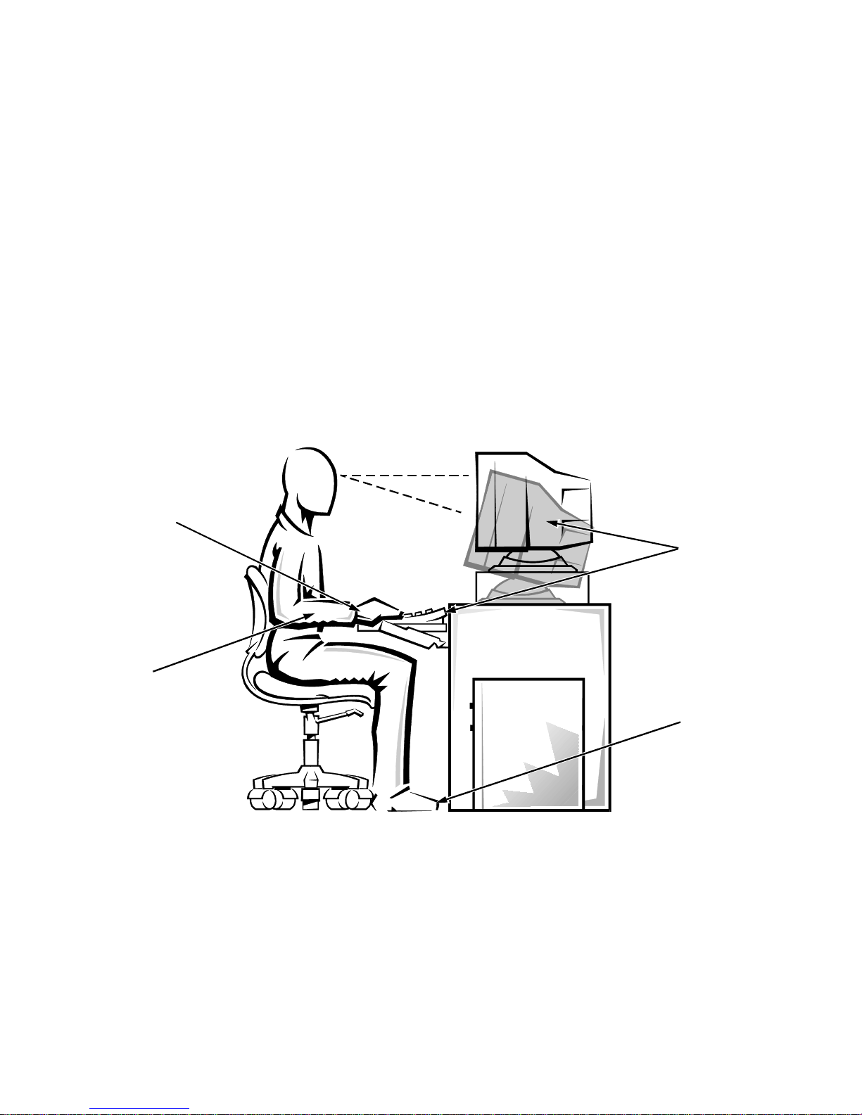
For comfort and efficiency, observe the following ergonomic guidelines when settin g up and using your
computer system:
•
Position your system so that the monitor and keyboard are directly in front of you as you work.
Special shelves are available (from Dell and other
sources) to help you correc tly position your
keyboard.
v
•
Set the monitor at a comfortable viewing distance
(usually 510 to 610 millimeters [20 to 24 inches]
from your eyes).
•
Make sure the monitor screen is at eye level or
slightly lower when you are sitting in front of the
monitor.
•
Adjust the tilt of the monitor, its contrast and brightness settings, and the lighting around you (such as
overhead lights, desk lamps, and the curtains or
blinds on nearby windows) to minimize reflections
and glare on the monitor screen.
•
Use a chair that provides good lower back support.
•
Keep your forearms horizontal with your wrists in a
neutral, comfortable position while using the keyboard or mouse.
monitor screen at or below eye level
wrists relaxed and flat
•
Always leave space to rest your hands while using
the keyboard or mouse.
•
Let your upper arms hang naturally at your sides.
•
Sit erect, with your feet resting on the floor and your
thighs level.
•
When sitting, make sure the weight of your legs is on
your feet and not on the front of your chair seat.
Adjust your chair’s height or use a footrest, if necessary, to maintain proper posture.
•
Var y your work act ivit ies. T r y to or gan ize your work
so that you do not have to type for extended periods
of time without stopping. When you stop typing, try
to do things that use both hands.
arms at desk level
monitor and keyboard
positioned directly
in front of user
feet flat on the floor
vi

W
hen Working With Your
Computer
Take note of these safety guidelines when appropriate:
•
To help avoid possible damage to the system board,
wait five seconds after turning off the system before
disconnecting a peripheral device from the
computer.
•
When you disconnect a cable, pull on its connector
or on its strain-relief loop, not on the cable itself.
Some cables have a connector with locking tabs; if
you are disconnecting this type of cable, press in on
the locking tabs before disconnecting the cable. As
you pull connectors apart, keep them evenly aligned
to avoid bending any connector pins. Also, before
you connect a cable, make sure both connectors are
correctly oriented and aligned.
vii

viii

Preface
A
bout This Guide
This guide is intended for anyone who uses a Dell PowerEdge 4200 computer system. The guide can be used by
both first-time and experienced computer users who want
to learn about the features and operation of their systems
or who want to upgrade their systems. The chapters and
appendices are summarized as follows:
•
Everyone should read Chapter 1, “Introduction,” for
an overview of the system features, a description of
the controls and indicators on the front panel, and
general information on connecting external devices
to the back panel of the computer and using the system security features.
•
If you want to instal l video driv ers for your op erating
system, you should read Chapter 2, “Using the Dell
Server Assistant CD.”
•
Everyone should read the first few sections of Chapter 3, “Installing and Configuring SCSI Drivers,” to
find out which small computer system interface
(SCSI) device drivers (if any) are required for a particular system configuration. If you need to install
and configure particular SCSI device drivers, you
should read the appropriate section for your operating system.
removed, or have additional memory installed, you
must run this utility.
•
Chapter 6, “Installing SCSI Hard-Disk Drives,”
describes how to install SCSI hard-disk drives in the
computer’s six internal drive bays.
•
Appendix A, “Technical Specifications,” and Appendix B, “I/O Ports and Co nnecto rs,” are in tended
primarily as reference material for users interested in
learning more about the details o f th e s ystem.
•
Appendix C, “Maintaining the System,” describes
preventive maintenance procedures that you should
perform regularly to keep your computer system in
top operating condition.
•
Appendix D, “Regulatory Notices,” is for users who
are interested in which regulatory agencies have
tested and approved the Dell PowerEdge 4200
systems.
•
Appendix E, “Warranties and Return Policy,”
describes the warranties for the Dell PowerEdge
4200 systems and the “Total Satisfaction” Return
Policy.
•
The Glossary provides definitions of terms, acronyms, and abbreviations used in this guide.
•
Everyone should read the first several sections of
Chapter 4, “Using the System Setup Program,” to
familiarize themselves with this important progr am.
If you want to make configuration changes to your
system or use the password features, y ou should read
the rest of Chapter 4.
•
Everyone should read Chapter 5, “Using the EISA
Configuration Ut ility .” If you change sett ings for one
of the built-in devices, have an Extended IndustryStandard Architecture (EISA) or Industry-Standard
Architecture (ISA) expansion card added or
W
arranty and Return Policy
Information
Dell Computer Corporation (“Dell”) manufactures its
hardware products from parts and components that are
new or equivalent to new in accordance with industrystandard practices. For information about the Dell
warranty for your system, see Appendix E, “Warranties
and Return Policy.”
ix

O
ther Documents You May Need
In addition to this User’s Guide, the following documenta-
tion is included with your system:
•
The Installation and Troubleshooting Guide, which
includes troubleshooting procedures and instructions
for using the CD-based diagnostics to test your com puter system. System upgrade instructions are
provided for trained service technicians.
•
The Intel® LANDesk® Server Manager suite, which
includes a CD-ROM containing the server manager
software, plus the following documents: LANDesk
Server Manager Setup Guide, LANDesk Server
Manager User’s Guide, LANDesk Server Control
Installation and User’s Guide, LANDesk Server
Monitor Module Inst allation and User’s Guide.
You may also have one or more of the following
documents.
NOTE: Documentation updates are sometimes included
with your system to describe changes to your system or
software. Always r ea d these upda tes
other documentatio n beca use the updat es o ften contai n th e
latest information.
•
The Dell Hardware Instrumentation Package for
Intel LANDesk Server Manager User’s Guide
describes t his server management application software’s extensive capabilities.
before
consulting any
reference material intended for experienced users or
technicians.
N
otational Conventions
The follow ing subsections describe notational conventions used in this docume nt.
Warnings, Cautions, and Notes
Throughout this guide, there may be blocks of text
printed in bold type within boxes or in italic type. These
blocks are warnings, cautions, and notes, and they are
used as follows:
WARNING: A WARNING indicates the potential
for bodily harm and tells you how to avoid the
problem.
CAUTION: A CAUTION indicates either potential damage to hardware or loss of data a nd tells
you how to avoid the problem.
NOTE: A NOTE indicates important information that
helps you make better use of your computer system.
•
The Dell PowerEdge rack kit installation documentation provides detailed instructions for service
technicians.
•
Operating system documentation is included if you
ordered your operating system software from Dell.
This documentation describes how to install (if necessary), configure, and use your operating system
software.
•
Documentation is included with any options you
purchase separately from your system, such as the
Dell PowerEdge Expandable RAID Controller host
adapter. This documentation includes information
that you need to configure and install these options
in your system.
•
Technical information files—sometimes called
“readme” files—may be installed on your hard-disk
drive to provide last-minute updates about technical
changes to your system or advanced technical
x
Typographical Conventions
The following list defines (where appropriate) specific
elements of text and illustrates the typographical co nventions used throughout this document as visual cues for
those elements:
•
Keycaps, the labeling that appears on the keys on a
keyboard, are enclosed in angle brackets.
Example: <Enter>
•
Key combinations are series of keys to be pressed
simultaneously (unless otherwise indicated) to perform a single function.
Example: <Ctrl><Alt><Enter>
•
Commands presented in lowercase bold are for reference purposes only and are not intended to be typed
when referenced.
Example: “Use the format command to . . . .”

In contrast, commands presented in the Cour ier New
font are part of an instruction and intended to be
typed.
Example: “Type
in drive A.”
•
Filenames and directory names are presented in
lowercase bold.
Examples: autoexec.bat and c:\windows
•
Syntax lines consist of a command and all its
possible parameters. Commands are displayed in
lowercase bold; variable parameters (those for which
you substitute a value) are displayed in lowercase
italics; constant parameters are displayed in lowercase bold. The brackets indicate items that are
optional.
Example: del [drive:] [path] filename [/p]
•
Command lines consist of a command and may
include one or more of the command’s possible
format a:
to format the diskette
parameters. Command lines are presented in the
Courier New font.
Example:
•
Screen text is text that appears on the screen of your
monitor or display. It can be a system message, for
example, or it can be text that you are instructed to
type as part of a command (referr ed to as a command
line). Screen text is presented in the Courier New
font.
Example: The following message appears on your
screen:
No boot device available
Example: “Type
•
Variables are placeholders for which you s ubstitute a
value. They are presented in italics.
Example: DIMM_x (where x represents the DIMM
socket designation)
del c:\myfile.doc
md c:\dos
and press <Enter>.”
xi

xii

Contents
Chapter 1
Introduction . . . . . . . . . . . . . . . . . . . . . . . . . . . . . . . . . . . . . . . . . . . 1-1
System Features. . . . . . . . . . . . . . . . . . . . . . . . . . . . . . . . . . . . . . . . . . . . . . . . . . . . . . 1-1
Supported Operating Systems . . . . . . . . . . . . . . . . . . . . . . . . . . . . . . . . . . . . . . . 1-3
Front Panel . . . . . . . . . . . . . . . . . . . . . . . . . . . . . . . . . . . . . . . . . . . . . . . . . . . . . . . . . 1-3
Connecting External Devices . . . . . . . . . . . . . . . . . . . . . . . . . . . . . . . . . . . . . . . . . . . 1-3
Preventing Unauthorized Access Inside the Computer. . . . . . . . . . . . . . . . . . . . . . . . 1-4
Physically Securing the Computer . . . . . . . . . . . . . . . . . . . . . . . . . . . . . . . . . . . . . . . 1-4
Getting Help . . . . . . . . . . . . . . . . . . . . . . . . . . . . . . . . . . . . . . . . . . . . . . . . . . . . . . . . 1-4
Chapter 2
Using the Dell Server Assistant CD . . . . . . . . . . . . . . . . . . . . . . . . 2-1
Booting the CD . . . . . . . . . . . . . . . . . . . . . . . . . . . . . . . . . . . . . . . . . . . . . . . . . . . . . . 2-1
CD Main Menu . . . . . . . . . . . . . . . . . . . . . . . . . . . . . . . . . . . . . . . . . . . . . . . . . . . . . . 2-1
Choose Language. . . . . . . . . . . . . . . . . . . . . . . . . . . . . . . . . . . . . . . . . . . . . . . . . 2-1
Configure the System . . . . . . . . . . . . . . . . . . . . . . . . . . . . . . . . . . . . . . . . . . . . . . 2-1
Run System Utilities . . . . . . . . . . . . . . . . . . . . . . . . . . . . . . . . . . . . . . . . . . . . . . 2-1
Use Online Manuals. . . . . . . . . . . . . . . . . . . . . . . . . . . . . . . . . . . . . . . . . . . . . . . 2-1
Create Diskettes . . . . . . . . . . . . . . . . . . . . . . . . . . . . . . . . . . . . . . . . . . . . . . . . . . 2-1
Utility Partition . . . . . . . . . . . . . . . . . . . . . . . . . . . . . . . . . . . . . . . . . . . . . . . . . . . . . . 2-2
Video Drivers . . . . . . . . . . . . . . . . . . . . . . . . . . . . . . . . . . . . . . . . . . . . . . . . . . . . . . . 2-2
Installing Video Drivers for Windows NT 3.51. . . . . . . . . . . . . . . . . . . . . . . . . . 2-2
Asset Tag Utility . . . . . . . . . . . . . . . . . . . . . . . . . . . . . . . . . . . . . . . . . . . . . . . . . . . . . 2-2
Using the Asset Tag Utility . . . . . . . . . . . . . . . . . . . . . . . . . . . . . . . . . . . . . . . . . 2-2
Assigning and Deleting an Asset Tag Number. . . . . . . . . . . . . . . . . . . . . . . 2-3
xiii

Chapter 3
Installing and Configuring SCSI Drivers. . . . . . . . . . . . . . . . . . . . 3-1
Installing SCSI Drivers for a Dell PowerEdge Expandable
RAID Controller in Windows NT 4.0 . . . . . . . . . . . . . . . . . . . . . . . . . . . . . . . . . . . . 3-1
The readme.txt File. . . . . . . . . . . . . . . . . . . . . . . . . . . . . . . . . . . . . . . . . . . . . . . . . . 3-2
The SCSISelect Utility . . . . . . . . . . . . . . . . . . . . . . . . . . . . . . . . . . . . . . . . . . . . . . . . 3-2
SCSISelect Default Settings . . . . . . . . . . . . . . . . . . . . . . . . . . . . . . . . . . . . . . . . 3-2
SCSI Bus Interface Definitions . . . . . . . . . . . . . . . . . . . . . . . . . . . . . . . . . . 3-3
Boot Device Options. . . . . . . . . . . . . . . . . . . . . . . . . . . . . . . . . . . . . . . . . . . . . . 3-3
SCSI Device/Configuration Settings. . . . . . . . . . . . . . . . . . . . . . . . . . . . . . . . . . 3-3
Advanced Host Adapter Settings. . . . . . . . . . . . . . . . . . . . . . . . . . . . . . . . . 3-4
Starting the SCSISelect Utility . . . . . . . . . . . . . . . . . . . . . . . . . . . . . . . . . . . . . . 3-5
Using SCSISelect Menus . . . . . . . . . . . . . . . . . . . . . . . . . . . . . . . . . . . . . . . . . . 3-5
Using the SCSI Disk Utilities . . . . . . . . . . . . . . . . . . . . . . . . . . . . . . . . . . . . . . . 3-5
Exiting SCSISelect . . . . . . . . . . . . . . . . . . . . . . . . . . . . . . . . . . . . . . . . . . . . . . . 3-6
Installation for the Microsoft Windows NT Operating System . . . . . . . . . . . . . . . . . 3-6
Installation Overview . . . . . . . . . . . . . . . . . . . . . . . . . . . . . . . . . . . . . . . . . . . . . 3-6
Installing Windows NT and the Driver. . . . . . . . . . . . . . . . . . . . . . . . . . . . . . . . 3-6
Performing a Windows NT 3.51 Installation. . . . . . . . . . . . . . . . . . . . . . . . 3-6
Using Windows NT to Install or Update the Driver . . . . . . . . . . . . . . . . . . . . . . 3-7
Installing or Updating the Driver With Windows NT 4.0 . . . . . . . . . . . . . . 3-7
Installing or Updating the Driver With Windows NT 3.51 . . . . . . . . . . . . . 3-8
Removing a Host Adapter . . . . . . . . . . . . . . . . . . . . . . . . . . . . . . . . . . . . . . 3-9
Swapping a Host Adapter . . . . . . . . . . . . . . . . . . . . . . . . . . . . . . . . . . . . . . 3-9
Troubleshooting for Windows NT. . . . . . . . . . . . . . . . . . . . . . . . . . . . . . . 3-10
Installation for Novell NetWare. . . . . . . . . . . . . . . . . . . . . . . . . . . . . . . . . . . . . . . . 3-10
Installation Overview . . . . . . . . . . . . . . . . . . . . . . . . . . . . . . . . . . . . . . . . . . . . 3-10
Installing EZ-SCSI . . . . . . . . . . . . . . . . . . . . . . . . . . . . . . . . . . . . . . . . . . . . . . 3-11
Calculating the Slot Number. . . . . . . . . . . . . . . . . . . . . . . . . . . . . . . . . . . . . . . 3-12
Installing NetWare and the Driver . . . . . . . . . . . . . . . . . . . . . . . . . . . . . . . . . . 3-12
Performing a NetWare 4.11 SMP Installation. . . . . . . . . . . . . . . . . . . . . . 3-12
Performing a NetWare 3.12 Installation . . . . . . . . . . . . . . . . . . . . . . . . . . 3-13
Using NetWare to Install or Update the Driver. . . . . . . . . . . . . . . . . . . . . . . . . 3-14
Using the load Command Line Options . . . . . . . . . . . . . . . . . . . . . . . . . . . . . . 3-15
Bit Mask Options. . . . . . . . . . . . . . . . . . . . . . . . . . . . . . . . . . . . . . . . . . . . 3-16
Sample load Command . . . . . . . . . . . . . . . . . . . . . . . . . . . . . . . . . . . . . . . 3-16
Using startup.ncf and autoexec.ncf. . . . . . . . . . . . . . . . . . . . . . . . . . . . . . . . . 3-16
Using SCSI Devices . . . . . . . . . . . . . . . . . . . . . . . . . . . . . . . . . . . . . . . . . . . . . 3-16
Booting From a SCSI Device. . . . . . . . . . . . . . . . . . . . . . . . . . . . . . . . . . . 3-17
xiv

Formatting Media . . . . . . . . . . . . . . . . . . . . . . . . . . . . . . . . . . . . . . . . . . . . 3-17
Using Removable Media. . . . . . . . . . . . . . . . . . . . . . . . . . . . . . . . . . . . . . . 3-17
Using Drives Tested and Approved for NetWare. . . . . . . . . . . . . . . . . . . . 3-18
Using the NetWare Tape Backup Utility . . . . . . . . . . . . . . . . . . . . . . . . . . 3-19
Setting Up a CD-ROM Drive With NetWare 3.12 or 4.11 SMP . . . . . . . . 3 -19
Optimizing Performance . . . . . . . . . . . . . . . . . . . . . . . . . . . . . . . . . . . . . . . . . . 3-19
Troubleshooting for NetWare . . . . . . . . . . . . . . . . . . . . . . . . . . . . . . . . . . . . . . 3 -19
Non–Host-Adapter Specific . . . . . . . . . . . . . . . . . . . . . . . . . . . . . . . . . . . . 3-20
Host-Adapter Specific. . . . . . . . . . . . . . . . . . . . . . . . . . . . . . . . . . . . . . . . . 3-20
Chapter 4
Using the System Setup Program . . . . . . . . . . . . . . . . . . . . . . . . . 4-1
System Setup Screens . . . . . . . . . . . . . . . . . . . . . . . . . . . . . . . . . . . . . . . . . . . . . . . . . 4-1
Entering the System Setup Program . . . . . . . . . . . . . . . . . . . . . . . . . . . . . . . . . . . . . . 4-2
Main Menu Categories . . . . . . . . . . . . . . . . . . . . . . . . . . . . . . . . . . . . . . . . . . . . . . . . 4-3
Time . . . . . . . . . . . . . . . . . . . . . . . . . . . . . . . . . . . . . . . . . . . . . . . . . . . . . . . . . . . 4-4
Date . . . . . . . . . . . . . . . . . . . . . . . . . . . . . . . . . . . . . . . . . . . . . . . . . . . . . . . . . . . 4-4
Diskette Drive A and Diskette Drive B . . . . . . . . . . . . . . . . . . . . . . . . . . . . . . . . 4-4
Fast Video BIOS . . . . . . . . . . . . . . . . . . . . . . . . . . . . . . . . . . . . . . . . . . . . . . . . . 4-4
Memory Cache. . . . . . . . . . . . . . . . . . . . . . . . . . . . . . . . . . . . . . . . . . . . . . . . . . . 4-4
Boot Sequence . . . . . . . . . . . . . . . . . . . . . . . . . . . . . . . . . . . . . . . . . . . . . . . . . . . 4-4
Boot Options Submenu Categories. . . . . . . . . . . . . . . . . . . . . . . . . . . . . . . . 4-5
Num Lock. . . . . . . . . . . . . . . . . . . . . . . . . . . . . . . . . . . . . . . . . . . . . . . . . . . . . . . 4-6
Speaker. . . . . . . . . . . . . . . . . . . . . . . . . . . . . . . . . . . . . . . . . . . . . . . . . . . . . . . . . 4-6
Processor 1. . . . . . . . . . . . . . . . . . . . . . . . . . . . . . . . . . . . . . . . . . . . . . . . . . . . . . 4-6
Processor 2. . . . . . . . . . . . . . . . . . . . . . . . . . . . . . . . . . . . . . . . . . . . . . . . . . . . . . 4-6
Level 2 Cache. . . . . . . . . . . . . . . . . . . . . . . . . . . . . . . . . . . . . . . . . . . . . . . . . . . . 4-6
Base Memory. . . . . . . . . . . . . . . . . . . . . . . . . . . . . . . . . . . . . . . . . . . . . . . . . . . . 4-6
Extended Memory . . . . . . . . . . . . . . . . . . . . . . . . . . . . . . . . . . . . . . . . . . . . . . . . 4-6
Video Memory. . . . . . . . . . . . . . . . . . . . . . . . . . . . . . . . . . . . . . . . . . . . . . . . . . . 4-6
Service Tag. . . . . . . . . . . . . . . . . . . . . . . . . . . . . . . . . . . . . . . . . . . . . . . . . . . . . . 4-7
Asset Tag . . . . . . . . . . . . . . . . . . . . . . . . . . . . . . . . . . . . . . . . . . . . . . . . . . . . . . . 4-7
Advanced Menu Categories . . . . . . . . . . . . . . . . . . . . . . . . . . . . . . . . . . . . . . . . . . . . 4-7
Serial Port 1 . . . . . . . . . . . . . . . . . . . . . . . . . . . . . . . . . . . . . . . . . . . . . . . . . . . . . 4-8
Serial Port 2 . . . . . . . . . . . . . . . . . . . . . . . . . . . . . . . . . . . . . . . . . . . . . . . . . . . . . 4-8
Parallel Port . . . . . . . . . . . . . . . . . . . . . . . . . . . . . . . . . . . . . . . . . . . . . . . . . . . . . 4-8
Parallel Mode. . . . . . . . . . . . . . . . . . . . . . . . . . . . . . . . . . . . . . . . . . . . . . . . . . . . 4-8
Diskette Controller. . . . . . . . . . . . . . . . . . . . . . . . . . . . . . . . . . . . . . . . . . . . . . . . 4-8
On-Board SCSI-A . . . . . . . . . . . . . . . . . . . . . . . . . . . . . . . . . . . . . . . . . . . . . . . . 4-8
xv

On-Board SCSI-B . . . . . . . . . . . . . . . . . . . . . . . . . . . . . . . . . . . . . . . . . . . . . . . . 4-8
PCI Scan Sequence . . . . . . . . . . . . . . . . . . . . . . . . . . . . . . . . . . . . . . . . . . . . . . . 4-8
Use MP Specification . . . . . . . . . . . . . . . . . . . . . . . . . . . . . . . . . . . . . . . . . . . . . 4-8
PS/2 Mouse . . . . . . . . . . . . . . . . . . . . . . . . . . . . . . . . . . . . . . . . . . . . . . . . . . . . . 4-8
Security Menu Categories . . . . . . . . . . . . . . . . . . . . . . . . . . . . . . . . . . . . . . . . . . . . . 4-9
Supervisor Password Is. . . . . . . . . . . . . . . . . . . . . . . . . . . . . . . . . . . . . . . . . . . . 4-9
User Password Is. . . . . . . . . . . . . . . . . . . . . . . . . . . . . . . . . . . . . . . . . . . . . . . . . 4-9
Set Supervisor Password. . . . . . . . . . . . . . . . . . . . . . . . . . . . . . . . . . . . . . . . . . 4-10
Set User Password. . . . . . . . . . . . . . . . . . . . . . . . . . . . . . . . . . . . . . . . . . . . . . . 4-10
Password on Boot . . . . . . . . . . . . . . . . . . . . . . . . . . . . . . . . . . . . . . . . . . . . . . . 4-10
Diskette Access. . . . . . . . . . . . . . . . . . . . . . . . . . . . . . . . . . . . . . . . . . . . . . . . . 4-10
System Backup Reminder. . . . . . . . . . . . . . . . . . . . . . . . . . . . . . . . . . . . . . . . . 4-10
Virus Check Reminder . . . . . . . . . . . . . . . . . . . . . . . . . . . . . . . . . . . . . . . . . . . 4-10
Exit Menu Categories. . . . . . . . . . . . . . . . . . . . . . . . . . . . . . . . . . . . . . . . . . . . . . . . 4-11
Save Changes & Exit. . . . . . . . . . . . . . . . . . . . . . . . . . . . . . . . . . . . . . . . . . . . . 4-11
Exit Without Saving Changes. . . . . . . . . . . . . . . . . . . . . . . . . . . . . . . . . . . . . . 4-11
Get Default Values . . . . . . . . . . . . . . . . . . . . . . . . . . . . . . . . . . . . . . . . . . . . . . 4-11
Load Previous Values. . . . . . . . . . . . . . . . . . . . . . . . . . . . . . . . . . . . . . . . . . . . 4-11
Save Changes . . . . . . . . . . . . . . . . . . . . . . . . . . . . . . . . . . . . . . . . . . . . . . . . . . 4-11
Using the Password Features . . . . . . . . . . . . . . . . . . . . . . . . . . . . . . . . . . . . . . . . . . 4-12
Using the Supervisor Password Feature . . . . . . . . . . . . . . . . . . . . . . . . . . . . . . 4-12
Assigning a Supervisor Password. . . . . . . . . . . . . . . . . . . . . . . . . . . . . . . . . . . 4-12
Using Your Supervisor Password to Secure Your System . . . . . . . . . . . . . . . . 4-12
Operating With a Supervisor Password Enabled . . . . . . . . . . . . . . . . . . . . . . . 4-13
Deleting or Changing an Existing Supervisor Password . . . . . . . . . . . . . . . . . 4-13
Using the User Password Feature . . . . . . . . . . . . . . . . . . . . . . . . . . . . . . . . . . . 4-13
Assigning a User Password. . . . . . . . . . . . . . . . . . . . . . . . . . . . . . . . . . . . . . . . 4-14
Using Your User Password to Secure Your System . . . . . . . . . . . . . . . . . . . . . 4-14
Deleting or Changing an Existing User Password . . . . . . . . . . . . . . . . . . . . . . 4-14
Disabling a Forgotten Password . . . . . . . . . . . . . . . . . . . . . . . . . . . . . . . . . . . . 4-14
Password Options . . . . . . . . . . . . . . . . . . . . . . . . . . . . . . . . . . . . . . . . . . . . . . . 4-15
Responding to Error Messages. . . . . . . . . . . . . . . . . . . . . . . . . . . . . . . . . . . . . . . . . 4-15
Chapter 5
Using the EISA Configuration Utility . . . . . . . . . . . . . . . . . . . . . . . 5-1
Configuring EISA, ISA, and PCI Expansion Cards. . . . . . . . . . . . . . . . . . . . . . . . . . 5-1
System Board Options . . . . . . . . . . . . . . . . . . . . . . . . . . . . . . . . . . . . . . . . . . . . . . . . 5-1
When to Run the EISA Configuration Utility . . . . . . . . . . . . . . . . . . . . . . . . . . . . . . 5-2
xvi

How to Run the EISA Configuration Utility. . . . . . . . . . . . . . . . . . . . . . . . . . . . . . . . 5-2
Making Selections in the EISA Configuration Utility . . . . . . . . . . . . . . . . . . . . . 5-3
Using Online Instructions . . . . . . . . . . . . . . . . . . . . . . . . . . . . . . . . . . . . . . . . . . 5-3
Starting the EISA Configuration Utility . . . . . . . . . . . . . . . . . . . . . . . . . . . . . . . . . . . 5-3
Main Menu . . . . . . . . . . . . . . . . . . . . . . . . . . . . . . . . . . . . . . . . . . . . . . . . . . . . . . . . . 5-4
Learn About Configuring Your Computer. . . . . . . . . . . . . . . . . . . . . . . . . . . . . . 5-4
Configure Computer. . . . . . . . . . . . . . . . . . . . . . . . . . . . . . . . . . . . . . . . . . . . . . . 5-4
Step 1: Important EISA Configuration Information. . . . . . . . . . . . . . . . . . . 5-4
Step 2: Add or Remove Boards . . . . . . . . . . . . . . . . . . . . . . . . . . . . . . . . . . 5-5
Step 3: View or Edit Details . . . . . . . . . . . . . . . . . . . . . . . . . . . . . . . . . . . . . 5-6
Step 4: Examine Switches or Print Report . . . . . . . . . . . . . . . . . . . . . . . . . 5-10
Step 5: Save and Exit . . . . . . . . . . . . . . . . . . . . . . . . . . . . . . . . . . . . . . . . . 5-10
Set Date and Set Time . . . . . . . . . . . . . . . . . . . . . . . . . . . . . . . . . . . . . . . . . . . . 5-10
Maintain System Configuration Diskette. . . . . . . . . . . . . . . . . . . . . . . . . . . . . . 5-10
Exit From This Utility . . . . . . . . . . . . . . . . . . . . . . . . . . . . . . . . . . . . . . . . . . . . 5-10
Advanced Menu . . . . . . . . . . . . . . . . . . . . . . . . . . . . . . . . . . . . . . . . . . . . . . . . . . . . 5-10
Lock/Unlock Boards . . . . . . . . . . . . . . . . . . . . . . . . . . . . . . . . . . . . . . . . . . . . . 5-10
View Additional System Information Menu . . . . . . . . . . . . . . . . . . . . . . . . . . . 5-11
Set Verification Mode Menu . . . . . . . . . . . . . . . . . . . . . . . . . . . . . . . . . . . . . . . 5-11
Maintain SCI Files Menu. . . . . . . . . . . . . . . . . . . . . . . . . . . . . . . . . . . . . . . . . . 5-11
Resolving Resource Conflicts. . . . . . . . . . . . . . . . . . . . . . . . . . . . . . . . . . . . . . . . . . 5-11
Removing a Card That Conflicts With the Card You Just Installed . . . . . . . . . 5-12
Modeling Mode. . . . . . . . . . . . . . . . . . . . . . . . . . . . . . . . . . . . . . . . . . . . . . . . . . . . . 5-12
Using the Password Features. . . . . . . . . . . . . . . . . . . . . . . . . . . . . . . . . . . . . . . . . . . 5-12
How Password Security Works . . . . . . . . . . . . . . . . . . . . . . . . . . . . . . . . . . . . . 5-13
Assigning or Changing a Supervisor Password . . . . . . . . . . . . . . . . . . . . . . . . . 5-13
Deleting an Existing Supervisor Password . . . . . . . . . . . . . . . . . . . . . . . . . . . . 5-14
Assigning or Changing a User Password. . . . . . . . . . . . . . . . . . . . . . . . . . . . . . 5-14
Deleting an Existing User Password . . . . . . . . . . . . . . . . . . . . . . . . . . . . . . . . . 5-15
Disabling a Forgotten Password. . . . . . . . . . . . . . . . . . . . . . . . . . . . . . . . . . . . . 5-15
Chapter 6
Installing SCSI Hard-Disk Drives . . . . . . . . . . . . . . . . . . . . . . . . . . 6-1
Installing SCSI Hard-Disk Drives in the Internal Drive Bays . . . . . . . . . . . . . . . . . . 6-2
SCSI Hard-Disk Drive Configuration . . . . . . . . . . . . . . . . . . . . . . . . . . . . . . . . . 6-2
Removing and Installing a SCSI Hard-Disk Drive . . . . . . . . . . . . . . . . . . . . . . . 6-3
Removing a SCSI Hard-Disk Drive . . . . . . . . . . . . . . . . . . . . . . . . . . . . . . . 6-3
Installing a SCSI Hard-Disk Drive . . . . . . . . . . . . . . . . . . . . . . . . . . . . . . . . 6-3
xvii

Removing and Installing a SC SI Hard-Disk Drive
With the System Running . . . . . . . . . . . . . . . . . . . . . . . . . . . . . . . . . . . . . . . . . . 6-3
SCSI Hard-Disk Drive Indicator Patterns . . . . . . . . . . . . . . . . . . . . . . . . . . 6-3
Removing a SCSI Hard-Disk Drive With the System Running . . . . . . . . . 6-4
Installing a SCSI Hard-Disk Drive With the System Running . . . . . . . . . . 6-4
Configuring the Boot Device . . . . . . . . . . . . . . . . . . . . . . . . . . . . . . . . . . . . . . . . . . . 6-4
Partitioning and Formatting SCSI Hard-Disk Drives . . . . . . . . . . . . . . . . . . . . . 6-4
Appendix A
Technical Specifications. . . . . . . . . . . . . . . . . . . . . . . . . . . . . . . . . A-1
Appendix B
I/O Ports and Connectors . . . . . . . . . . . . . . . . . . . . . . . . . . . . . . . . B-1
I/O Ports and Connectors . . . . . . . . . . . . . . . . . . . . . . . . . . . . . . . . . . . . . . . . . . . . . . B-1
Serial and Parallel Ports . . . . . . . . . . . . . . . . . . . . . . . . . . . . . . . . . . . . . . . . . . . B-1
Adding an Expansion Card Containing Serial or Parallel Ports . . . . . . . . . B-2
Serial Port Connectors . . . . . . . . . . . . . . . . . . . . . . . . . . . . . . . . . . . . . . . . . B-3
Parallel Port Connector . . . . . . . . . . . . . . . . . . . . . . . . . . . . . . . . . . . . . . . . B-3
Keyboard and Mouse Connectors. . . . . . . . . . . . . . . . . . . . . . . . . . . . . . . . . . . . B-4
Keyboard Connector . . . . . . . . . . . . . . . . . . . . . . . . . . . . . . . . . . . . . . . . . . B-4
Mouse Connector. . . . . . . . . . . . . . . . . . . . . . . . . . . . . . . . . . . . . . . . . . . . . B-4
Video Connector . . . . . . . . . . . . . . . . . . . . . . . . . . . . . . . . . . . . . . . . . . . . . . . . . B-5
Server-Management Serial Port Connector. . . . . . . . . . . . . . . . . . . . . . . . . . . . . B-6
Appendix C
Maintaining the System. . . . . . . . . . . . . . . . . . . . . . . . . . . . . . . . . . C-1
Data Preservation . . . . . . . . . . . . . . . . . . . . . . . . . . . . . . . . . . . . . . . . . . . . . . . . . . . . C-1
Scheduling Backups . . . . . . . . . . . . . . . . . . . . . . . . . . . . . . . . . . . . . . . . . . . . . . C-1
Backup Devices. . . . . . . . . . . . . . . . . . . . . . . . . . . . . . . . . . . . . . . . . . . . . . . . . . C-1
Recovering Data . . . . . . . . . . . . . . . . . . . . . . . . . . . . . . . . . . . . . . . . . . . . . . . . . C-1
Cleaning System Components . . . . . . . . . . . . . . . . . . . . . . . . . . . . . . . . . . . . . . . . . . C-2
Recommended Tools and Accessories . . . . . . . . . . . . . . . . . . . . . . . . . . . . . . . . C-2
Cleaning the Computer, Monitor, and Keyboard Exteriors . . . . . . . . . . . . . . . . C-2
Cleaning Drives. . . . . . . . . . . . . . . . . . . . . . . . . . . . . . . . . . . . . . . . . . . . . . . . . . C-3
xviii
Environmental Factors . . . . . . . . . . . . . . . . . . . . . . . . . . . . . . . . . . . . . . . . . . . . . . . .C-3
Temperature . . . . . . . . . . . . . . . . . . . . . . . . . . . . . . . . . . . . . . . . . . . . . . . . . . . . .C-3
Humidity . . . . . . . . . . . . . . . . . . . . . . . . . . . . . . . . . . . . . . . . . . . . . . . . . . . . . . .C-3
Altitude. . . . . . . . . . . . . . . . . . . . . . . . . . . . . . . . . . . . . . . . . . . . . . . . . . . . . . . . .C-4
Dust and Particles. . . . . . . . . . . . . . . . . . . . . . . . . . . . . . . . . . . . . . . . . . . . . . . . .C-4
Corrosion . . . . . . . . . . . . . . . . . . . . . . . . . . . . . . . . . . . . . . . . . . . . . . . . . . . . . . .C-4
Electromagnetic and Radio Frequency Interference . . . . . . . . . . . . . . . . . . . . . .C-4
Magnetism . . . . . . . . . . . . . . . . . . . . . . . . . . . . . . . . . . . . . . . . . . . . . . . . . . . . . .C-5
Shock and Vibration. . . . . . . . . . . . . . . . . . . . . . . . . . . . . . . . . . . . . . . . . . . . . . .C-5
Power Source Interruptions . . . . . . . . . . . . . . . . . . . . . . . . . . . . . . . . . . . . . . . . . C-5
Power Protection Devices . . . . . . . . . . . . . . . . . . . . . . . . . . . . . . . . . . . . . . . . . . . . . .C-5
Surge Protectors. . . . . . . . . . . . . . . . . . . . . . . . . . . . . . . . . . . . . . . . . . . . . . . . . .C-6
Line Conditioners. . . . . . . . . . . . . . . . . . . . . . . . . . . . . . . . . . . . . . . . . . . . . . . . .C-6
Uninterruptible Power Supply . . . . . . . . . . . . . . . . . . . . . . . . . . . . . . . . . . . . . . .C-6
Appendix D
Regulatory Notices . . . . . . . . . . . . . . . . . . . . . . . . . . . . . . . . . . . . . D-1
FCC Notices (U.S. Only) . . . . . . . . . . . . . . . . . . . . . . . . . . . . . . . . . . . . . . . . . . . . . .D-1
Class A. . . . . . . . . . . . . . . . . . . . . . . . . . . . . . . . . . . . . . . . . . . . . . . . . . . . . . . . .D-1
Class B . . . . . . . . . . . . . . . . . . . . . . . . . . . . . . . . . . . . . . . . . . . . . . . . . . . . . . . . .D-1
IC Notice (Canada Only). . . . . . . . . . . . . . . . . . . . . . . . . . . . . . . . . . . . . . . . . . . . . . .D-2
EN 55022 Compliance (Czech Republic Only) . . . . . . . . . . . . . . . . . . . . . . . . . . . . .D-2
CE Notice . . . . . . . . . . . . . . . . . . . . . . . . . . . . . . . . . . . . . . . . . . . . . . . . . . . . . . . . . .D-3
VCCI Notices (Japan Only) . . . . . . . . . . . . . . . . . . . . . . . . . . . . . . . . . . . . . . . . . . . .D-3
Class 1 Notice . . . . . . . . . . . . . . . . . . . . . . . . . . . . . . . . . . . . . . . . . . . . . . . . . . .D-3
Class 2 Notice . . . . . . . . . . . . . . . . . . . . . . . . . . . . . . . . . . . . . . . . . . . . . . . . . . .D-3
Korean Regulatory Notice. . . . . . . . . . . . . . . . . . . . . . . . . . . . . . . . . . . . . . . . . . . . . .D-4
Class A Device. . . . . . . . . . . . . . . . . . . . . . . . . . . . . . . . . . . . . . . . . . . . . . . . . . .D-4
Class B Device. . . . . . . . . . . . . . . . . . . . . . . . . . . . . . . . . . . . . . . . . . . . . . . . . . .D-4
Polish Center for Testing and Certification Notice . . . . . . . . . . . . . . . . . . . . . . . . . . .D-4
8ZNBHBOJB1PMTLJFHP$FOUSVN#BEBËJ$FSUZGJLBDKJ
1P[PTUBFJOTUSVLDKFCF[QJFD[FËTUXB
. . . . . . . . . . . . . . . . . . . . . . . . . . . . . . . . . . . . . .D-4
NOM 024 Information (Mexico Only) . . . . . . . . . . . . . . . . . . . . . . . . . . . . . . . . . . . .D-5
Información para NOM 024 (únicamente para México). . . . . . . . . . . . . . . . . . . . . . .D-5
. . . . . . . . . . . . . . . . . . . . . . . .D-4
xix

Appendix E
Warranties and Return Policy. . . . . . . . . . . . . . . . . . . . . . . . . . . . . E-1
Limited Three-Year Warranty (U.S. and Canada Only) . . . . . . . . . . . . . . . . . . . . . . E-1
Coverage During Year One. . . . . . . . . . . . . . . . . . . . . . . . . . . . . . . . . . . . . . . . . E-1
Coverage During Years Two and Three . . . . . . . . . . . . . . . . . . . . . . . . . . . . . . . E-2
General . . . . . . . . . . . . . . . . . . . . . . . . . . . . . . . . . . . . . . . . . . . . . . . . . . . . . . . . E-2
“Total Satisfaction” Return Policy (U.S. and Canada Only) . . . . . . . . . . . . . . . . . . . E-3
Glossary
Index
Figures
Figure 1-1. Front Panel. . . . . . . . . . . . . . . . . . . . . . . . . . . . . . . . . . . . . . . . . . . . . 1-3
Figure 1-2. Keylock . . . . . . . . . . . . . . . . . . . . . . . . . . . . . . . . . . . . . . . . . . . . . . . 1-4
Figure 3-1. Bit Position. . . . . . . . . . . . . . . . . . . . . . . . . . . . . . . . . . . . . . . . . . . . 3-16
Figure 4-1. Main Menu of the System Setup Program. . . . . . . . . . . . . . . . . . . . . 4-3
Figure 4-2. Boot Options Submenu . . . . . . . . . . . . . . . . . . . . . . . . . . . . . . . . . . . 4-5
Figure 4-3. Advanced Menu of the System Setup Program. . . . . . . . . . . . . . . . . 4-7
Figure 4-4. Security Menu of the System Setup Program . . . . . . . . . . . . . . . . . . 4-9
Figure 4-5. Exit Menu of the System Setup Program. . . . . . . . . . . . . . . . . . . . . 4-11
Figure 5-1. EISA System Board Options Screen (Example) . . . . . . . . . . . . . . . . 5-9
Figure 6-1. Internal Drive Hardware . . . . . . . . . . . . . . . . . . . . . . . . . . . . . . . . . . 6-2
Figure 6-2. Installing a SCSI Hard-Disk Drive . . . . . . . . . . . . . . . . . . . . . . . . . . 6-3
Figure B-1. I/O Ports and Connectors. . . . . . . . . . . . . . . . . . . . . . . . . . . . . . . . . . B-2
Figure B-2. Pin Numbers for the Serial Port Connectors . . . . . . . . . . . . . . . . . . . B-3
Figure B-3. Pin Numbers for the Parallel Port Connector . . . . . . . . . . . . . . . . . . B-3
Figure B-4. Pin Numbers for the Keyboard Connector. . . . . . . . . . . . . . . . . . . . . B-4
Figure B-5. Pin Numbers for the Mouse Connector . . . . . . . . . . . . . . . . . . . . . . . B-5
Figure B-6. Pin Numbers for the Video Connector. . . . . . . . . . . . . . . . . . . . . . . . B-5
Figure B-7. Pin Numbers for the Server-Management Serial Port Connector . . . B-6
Tables
Table 2-1. Asset Tag Command-Line Options . . . . . . . . . . . . . . . . . . . . . . . . . . 2-3
Table 3-1. Default SCSI Controller Settings. . . . . . . . . . . . . . . . . . . . . . . . . . . . 3-2
Table 3-2. Expansion Slot Bus Numbers and Device Numbers . . . . . . . . . . . . 3-12
Table 3-3. load Command Line Options. . . . . . . . . . . . . . . . . . . . . . . . . . . . . . 3-15
Table 3-4. Files Necessary to Set Up Booting From a SCSI Device . . . . . . . . 3-17
Table 3-5. Drive Status Items . . . . . . . . . . . . . . . . . . . . . . . . . . . . . . . . . . . . . . 3-18
xx

Table 3-6. Read After Write Verify Options . . . . . . . . . . . . . . . . . . . . . . . . . . . 3-18
Table 4-1. System Setup Keys . . . . . . . . . . . . . . . . . . . . . . . . . . . . . . . . . . . . . . . 4-2
Table 4-2. Password Options . . . . . . . . . . . . . . . . . . . . . . . . . . . . . . . . . . . . . . . 4 -15
Table 6-1. SCSI Hard-Disk Drive Indicator Patterns. . . . . . . . . . . . . . . . . . . . . . 6-4
Table A-1. Technical Specifications. . . . . . . . . . . . . . . . . . . . . . . . . . . . . . . . . . .A-1
Table B-1. Pin Assignments for the Serial Port Connectors. . . . . . . . . . . . . . . . .B-3
Table B-2. Pin Assignments for the Parallel Port Connector . . . . . . . . . . . . . . . . B-4
Table B-3. Pin Assignments for the Keyboard Connector . . . . . . . . . . . . . . . . . .B-4
Table B-4. Pin Assignments for the Mouse Connector . . . . . . . . . . . . . . . . . . . .B-5
Table B-5. Pin Assignments for the Video Connector . . . . . . . . . . . . . . . . . . . . .B-5
Table B-6. Pin Assignments for the Server-Management
Serial Port Connector . . . . . . . . . . . . . . . . . . . . . . . . . . . . . . . . . . . . .B-6
xxi

xxii

Chapter 1
Introduction
D
ell® PowerEdge® 4200 systems are high-speed,
upgradable PC servers designed around the Intel
®
tium
II family of microprocessors. The PowerEdge
4200 systems provide both Extended Industry-Standard
Architecture (EISA) and high-performance Peripheral
Component Interconnect (PCI) expansion slots to allow
for future expansion of your system.
This chapter describes the major hardware and software
features of your system, provides information about the
indicators and controls on the computer’s front panel,
discusses connecting external devices to the computer,
and describes the system’s security features.
S
ystem Features
Your system offers the following major features:
•
One or two Pentium II micro processors that run at an
internal speed of 233, 266, or 300 megahertz (MHz)
and an external speed of 66 MHz.
The Intel microprocessor in your computer includes
™
MMX
multimedia and communications software. This
microprocessor incorporates new instructions and
data types as well as a technique called Single
Instruction, Multiple Data (SIMD) that allows the
microprocessor to process multiple data elements in
parallel, thereby improving overall system
performance.
•
A secondary cache of 512 kilobytes (KB) of stat ic
random-access memory (SRAM) is included within
the single-edge contact (SEC) cartridge, which also
contains the microprocessor. Math coprocessor functionality is internal to the microprocessor.
technology designed to handle complex
®
Pen-
•
Support for symmetric multiprocess i ng when a second microprocessor is installed. Symmetric
multiprocessing greatly improves overal l system performance by dividing microprocessor operations
between the two independent microprocessors . To
take advantage of this feature, you must us e an operating system that supports mul tiprocessi ng, s uch as
Microsoft
NetW are
NOTE: If you decide to upgrade your system by
installing a sec ond micr op r ocessor, you must order a
microprocessor upgrade kit from Dell. Not all versions of the Pentium II microprocessor will work
properly as a second microprocessor. The upgrade
kit from Dell contains the correct revision of the
microprocessor chip for use as a second microprocessor, as well as instruct ions for performing the
upgrade. (A trained ser vice te chnician must perf orm
the upgrade.) The second microprocessor must have
the same internal operating frequency as the first.
•
A minimum of 64 megabytes (MB) of system memory, upgradable to a maximum of 512 MB by
installing combinations of 32- and 128-MB dual inline memory modules (DIMMs) in the eight DIMM
sockets on the system board. Fast-page mode and
extended-data out (EDO) DIMMs are supported.
The buffered, 72-bit-wide DIMMs installed in
PowerEdge 4200 systems support error correction
code (ECC) to check for and correct memory errors.
ECC is performed by the memory controller in the
system chip set.
•
An optional redundant, hot-pl ug gab le power su ppl y
and power sup ply paralleling board.
•
Three redundant system cooling fans.
®
Windows NT® 3.51 or 4.0, or Novell®
®
4.11 SMP.
Introduction 1-1

•
A basic input/output system (BIOS) that resid e s in
flash memory and can be upgraded by diskette if
required.
•
System security features, including an intrusiondetection switch and keylocks for the hard-d is k dri ve
carriers and the system covers.
The system board includes the following built-in
features:
•
Five PCI and three EISA expansion-card connectors.
(A separate expansion-card slot is available for each
EISA and PCI expansion-card connector; there are
no shared expansion sl ot s.) The three PCI expansion
slots on the primary PCI bus support PCI video
cards.
•
An integrated video graphics array (VGA)compatible video subsystem with an ATI mach64
(264VT) PCI video controller connected to the PCI
local bus. The standard video subsyst em includes
1 MB of video memory. Maximum resolutions
(noninterlaced) are 640 x 480 pixels (16.7 million colors), 800 x 600 pixels (65,536 colors), and
1024 x 768 pixels (256 colors).
•
An integrated National Semiconductor PC87336
super input/output (I/O) controller that controls th e
bidirectional parallel port, two serial ports, and the
diskette drive in the externally accessible front bay.
The super I/O controller resides on the EISA bus.
The parallel port can be set to operate in the following
modes via the Parallel Mode
Setup program: output-only (AT-compatible), bidirectional (Personal S ystem/2 [P S/2]- compatible), o r
extended capabilities port (ECP).
•
An integrated Adaptec AIC-7880 Ultra/Wide small
computer system interface (SCSI) host adapter that
supports up to six internal SCSI hard-disk drives via
a standard SCSI backplane board and special SCSI
hard-disk drive carriers. The SCSI backplane automatically configures SCSI identification (ID)
numbers and S CSI termination on individual harddisk drives, greatly simplifying drive installation.
•
An integrated Adaptec AIC-7860 Ultra/Narrow
SCSI-II host adapter that supports up to four externally accessible SCSI devices in the external drive
bays. A SCSI CD-ROM drive is standard on PowerEdge 4200 systems.
category in the System
•
Up to two optional PowerEdge Expandable RAID
Controller host adapters that allow you to install and
remove SCSI hard-disk drives while the system is
running. For more information, see Chapter 6,
“Installing SCSI Hard-Disk Drives.”
•
Integrated server management circuitry that monitors
operation of the system fans as well as critical system
voltages and temperatures. The integrated server
management circuitry works in conjuncti on wi th the
Intel LANDesk
Hardware Instrumentation Package (HIP) server management application program. (See the Preface in this
guide for a list of document s t hat descri be inst al latio n
and use of the LANDesk Server Manager suite and
Dell HIP software.) You can also remotely monitor
server management functions by connecting an ext ernal Hayes-compatible Smart Modem to the remote
port connector on the computer’s back panel.
•
Built-in support for a diskette drive. A 1.44-MB diskette drive is included with your system.
•
A PS/2-style keyboard port and a PS/2-compatible
mouse port.
The following software is included with your Dell com puter system:
•
Video drivers for displaying many popular application programs in high-resolutio n modes. For more
information on these drivers, see “Video Drivers”
in Chapter 2, “Using the Dell Server Assistant CD.”
•
SCSI device drivers that allow your operating system to communicate with devices attached to the
built-in SCSI subsystem . For more in formation on
these drivers, see Chapter 3, “Installing and Configuring SCSI Drivers.”
•
The System Setup program for viewing and changing the system configuration information and for
setting or changing user-selectable options such as
passwords. For more information on this program,
see Chapter 4, “Using the System Setup Program.”
•
The EISA Configuration Utility, which allows you to
configure installed EISA expansion cards through
software rather than by hand. (You must also run the
EISA Configuration Utility when installing or
removing Industry-Standard Architecture [ISA]
cards or when changing the amount of system memory.) You can also use the EISA Configuration
®
Server Manager suite and the Dell
1-2 Dell PowerEdge 4200 Systems User’s Guide
Utility to set or change the user and supervisor passwords. For more information, see Chapter 5, “Using
the EISA Configuration Utility.”
Three indicator lights adjacent to each of the six SCSI
hard-disk drive bays provide the followin g information
on the drive in that bay:
•
The Intel LANDesk Server Manager suite and the
Dell HIP server management application program.
•
Dell system diagnostics for evaluating your computer’s components and devices. For information on
using the diagnostics, see Chapter 5, “Running the
System Diagnostics,” in the Installation and Trouble-
shooting Guide.
Supported Operating Systems
Dell supports the following network operating systems
for use on PowerEdge 4200 systems with one or two
microprocessors:
•
Microsoft Windows NT Server 3.51 and 4. 0
•
Novell NetWare 3. 1 2 a n d 4 . 11 SM P
Operating system software is not included with PowerEdge 4200 systems. If you p urchase the op erating system
software from Dell, installation instructions are inclu ded
on the CD-ROM with the operating system software.
NOTE: Installation services and support for other operating systems are available through Dell Plus. Contact
Dell for more information.
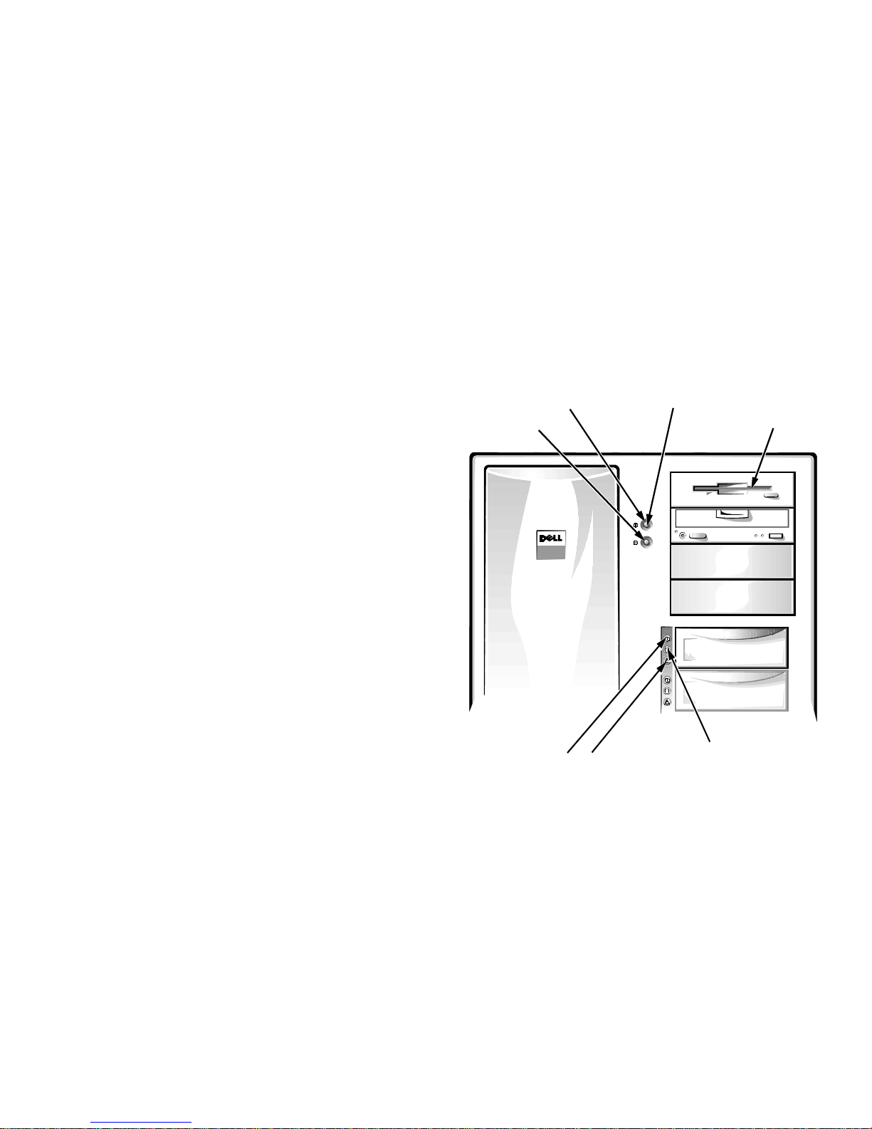
•
The green drive online indica tor (identified by a round
icon) lights up when the hard-disk drive is receiving
power.
•
The green drive activity indicator (identified by a
cylinder-shaped icon) lights up when data is bei ng
transferred to or from the hard-disk drive.
•
If an optional Dell PowerEdge Expandable RAID
Controller host adapter card is installed in the system, the amber drive failure indicator (identified by
a triangular icon) blinks if a disk failure is detected.
power button
reset button
power indicator
diskette-drive access
indicator (typical)
F
ront Panel
The following controls and indicators are easily accessible on the computer’s front panel (see Figure 1-1):
•
The power button contro ls th e PS_ ON si gn al, which
enables and disables the main power supply output
voltages. Th e g re e n power indi cator in the center of the
power button lights up when the computer is turned on.
You can also remotely shut down the PowerEdge
4200 system using software such as the Dell HIP
server management program.
•
The rese t button saves wear and tear on syst em components by allowing you to reboot (rest art) your
computer without turning the power off and then on
again.
•
The diskette-drive access indicator lights up when
data is being transferred to or from the diskette drive.
hard-disk drive
online indicator
Figure 1-1. Front Panel
C
onnecting External Devices
You can connect various external devices, such as a
mouse and printer, to the I/O ports and connector s on the
computer’s back panel. The system BIOS detects the
presence of external devices when you boot or reboot
hard-disk drive
failure indicator
hard-disk drive
activity indicator
Introduction 1-3
your system. When connecting external devices to your
computer, follow these guidelines:
•
Check the documentation that accompanied the
device for specific installation and configuration
instructions.
For example, most devices must be connected to a
particular I/O port or connector to operate properly.
Also, external devices such as a mouse or printer
usually requ ire you to load software files ca l led
device drivers into memory before they will work.
These software drivers help the computer recognize
and direct the operation of an external device.
•
Always attach external devices while your computer
is turned off. Then turn on the computer before
turning on any external devices, unless the documentation for the device specifies otherwise. (If the
computer does not seem to recognize the device, try
turning on the device before turni ng on the computer
to see if this resolves the problem.)
For information abou t enabling , disabli ng, or conf igurin g
I/O ports and connectors, see Chapter 4, “Using the System Setup Program,” or Chapter 5, “Using the EISA
Configuration Utility.” For detailed descriptions and
illustrations of each port and connector on the I/O panel,
see Appendix B, “I/O Ports and Connectors.”
If you are running the Dell HIP server management software, you can also monitor the intrusion detection alarm.
When enabled, this alarm notifies the software when the
left side panel is removed from the system. For more
information on the intrusion detection alarm, see your
Dell HIP server management documentation.
P
hysically Securing the
Computer
The security cable slot lets you attach a commercially
available antitheft device to the computer. Antitheft
devices for personal computers usually include a segment
of metal-stranded cable with an attached locking device
and associated key. To prevent unauthorized removal of
your computer, loop the cable around an immovable
object, insert the locking device into the security cable
slot on the back of the computer , and lock the device with
its associated key. (See Figure 2- 1 in the Installation and
Troubleshooting Guide for the location of the security
cable slot). Complete instructions for installing this kind
of antitheft device are usually included with the device.
NOTE: Antitheft devices are of differing designs. Before
purchasing such a d evice, make sure it will work with the
security cable slot on your computer.
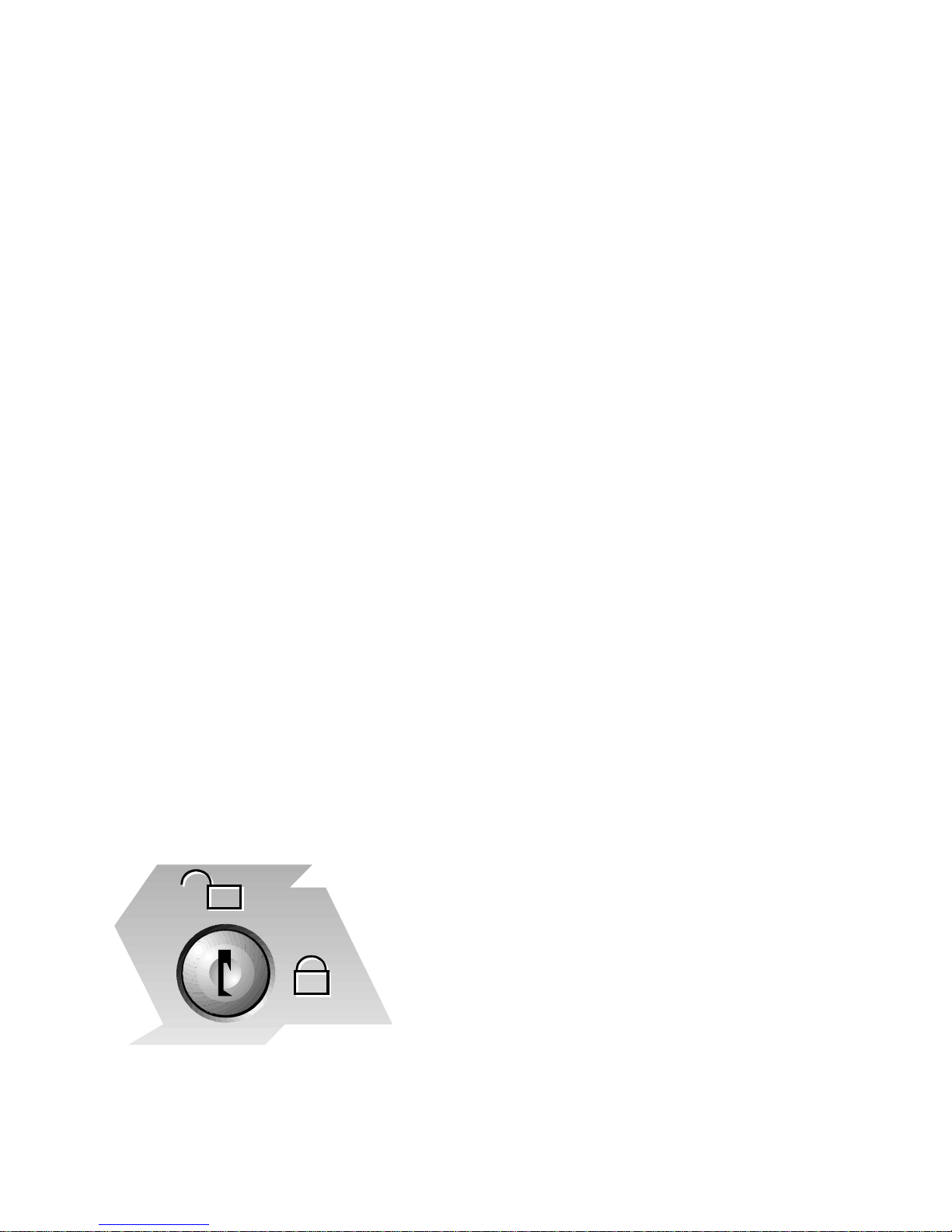
P
reventing Unauthorized Access
Inside the Computer
To prevent unauthorized access to the inside of the computer, yo u can lock the left and right computer cover s and
hard-disk drives using the keylocks (see Figure 1-2) and
the key provided with the system.
Figure 1-2. Keylock
1-4 Dell PowerEdge 4200 Systems User’s Guide
G
etting Help
If at any time you don’t unders tand a procedure descri bed
in this guide, or if your system does not perform as
expected, Dell provides a number of tools to help you.
For more information on these help tools, see Chapter 1 1,
“Getting Help,” in the Installation and Troubleshooting
Guide.

Chapter 2
Using the Dell Server Assistant CD
T
his chapter describes the bootable Dell Server Assis-
tant CD and tells you how to use the utilities, diagnostics,
documentation, driver s, and other it ems inclu ded on the
CD. This chapter also describes how to install the vide o
drivers for supported operating systems and how to use
the asset tag utility provided on the CD.
Choose Language
When the system boots, you are given the option of
choosing a language for the menus, help screens, messages, and online documentation. After you choose a
language, the main menu appears in the chosen language.
Configure the System
B
ooting the CD
The system must be running to insert the CD. To boot
the CD, insert it into the PowerEdge 4200 system’s
CD-ROM drive and press the reset button. When the system boots, the CD main menu appears.
If the CD does not boot, check the following:
•
In the System Setup program, the On-Boa r d SCSI B
category must be set to Enabled, the Diskette Controller category must be set to Enabled, the Diskette
Drive A category should be set to any setting except
Not Installed, and the Boot Sequence category must
be set to A: Then C: (see Chapter 4, “Using the System Setup Program”).
•
In the SCSISelect Utility, the BIOS Support for
Bootable CD-ROM category must be set to Enabled
(see Chapter 3, “Installing and Configuring SCSI
Drivers”).
CD
The main menu of the CD can include various options,
depending on your system configuration. The following
subsections describe some of the possible categories; the
main menu on your CD may contain add itional options.
Main Menu
You can use the options within the Configure the System
category for such tasks as running the EISA Configuration Utility from the CD or a diskette, or for configuring
a redundant array of inexpensive disks (RAID) subsystem (if applicable).
Run System Utilities
The options within the Run S ys tem Utilities category
allow you to run the system diagnostics and any other
utilities available on your CD.
Use Online Manuals
The Use Online Manuals category includes all available
online manuals. Selecting one of the online manuals
launches the Adobe
CD) and allows you to view or prin t th e online manual in
the language that you selected earlier.
NOTE: You can also copy the
(PDF) files from the CD and use them under your native
operating system.
Acrobat viewer (included on the
portable document format
Create Diskettes
The Create Diskettes category allows you to create diskettes of system utilities and operating system -specific
drivers as well as blank formatted diskettes.
Using the Dell Server Assistant CD 2-1

U
tility Partition
Dell PowerEdge 4200 systems may ha ve a utility partition installed on the hard-disk d rive. The Dell Server
Assistant CD contains more information on the utility
partition.
V
ideo Drivers
7. Select the A TI Graphics Accelerators
click Install.
Confirm your choice when prompted to do so, and
all appropriate files will be copied to the hard-disk
drive.
8. Restart Windows NT.
The system will start up using the ATI mach64 drivers in 640 x 480 mode an d display an appli cation that
allows you to choose a resolution.
option; then
You will need to install the video drivers for the operating
system you install on your PowerEdge 4200 system,
unless you purchased your system with the operating
system already installed by Dell. Use the following procedure to install the video drivers for the Windows NT
3.51 operating system. Windows NT 4.0 has the correct drivers already installed. NetWare provides a textual interface
and does not require video drivers.
Installing Video Drivers for
Windows NT 3.51
Select the Create Diskettes category from the Dell Server
Assistant CD main menu and create a diskette of software
drivers for Windows NT 3.51. After you make the diskette of drivers, use the following procedure to install the
video drivers:
1. Launch Windows NT.
2. Run the Windows NT Display program located in
the Control Panel in the Main group.
3. Select Change Display Type.
4. Select Change from the display options; then
select Other.
5. Insert the diskette of drivers into the diskette
drive on your system.
6. When prompted for the correct path, type
a:\ati
If the diskette is not in drive A, change the drive letter designation as appropriat e.
After the system reads the diskette, it displays the
ATI Graphics Accelerators
and press <Enter>.
option.
The maximum resolutions supported by the built-in
ATI mach64 video controller with 1 megabyt e ( MB)
of video memory are 640 x 480 pixels (16.7 million
colors) and 800 x 600 pixels (65,536 colors) (noninterlaced), and 1024 x 768 pixels (256 colors)
(interlaced).
NOTE: If you select a resolution that is not supported by the ATI mach64 (264VT) video controller
with 1 MB of memory, the operating system will substitute 640 x 480 in 256 colors.
A
sset Tag Utility
The Asset Tag utility allows you to enter an asset tag
number for your computer. The default System Setup
screens (see Figure 4-1, for example) do not show the
asset tag number unless you enter one using this utility.
NOTE: The Asset Tag utility works only on systems ru nning MS-D OS
®
.
Using the Asset Tag Utility
Use the following procedure to access the Asset Tag
utility:
1. If you have not alr e ady don e so, cr eate a boot able
system utility diskette from the CD.
2. Insert the diskette in drive A, and reboot the
system.
After you boot the system with the system utility diskette, you can use the Asset Tag utility to enter an
asset tag number that you or your organization
assign to the computer. You can also use the Asset
T ag utility to reenter the computer’s service tag number if that becomes necessary.
2-2 Dell PowerEdge 4200 Systems User’s Guide

You can view the asset tag number using the System
Setup program as described in Chapter 4, “Us ing the
System Setup Program.”
Assigning and Deleting an Asset Ta g
Number
An asset tag number can have up to ten characters; any
combination of characters, excluding spaces, is valid. To
assign or change an asset tag number, type
space followed by the new number; then press <Enter>.
For example, type the following command line and p ress
<Enter>:
asset 1234567890
When prompted to verify the asset tag number, type y
and press <Enter>. The system then displays the new or
modified asset tag number and the service tag number.
asset
and a
To delete the asset tag number without assigning a new
one, type
asset /d
and press <Enter>.
Table 2-1 lists the command line options you can use
with the Asset Tag utility. To use one of these options,
asset
type
.
and a space followed by the option.
Table 2-1. Asset Tag Command-Line Options
Asset Tag Option Description
/d Deletes the asset tag number
/? Displays the Ass e t Tag
utility help screen
Using the Dell Server Assistant CD 2-3

2-4 Dell PowerEdge 4200 Systems User’s Guide

Chapter 3
Installing and Configuring SCSI Drivers
T
his chapter describes how t o in st all and conf igure the
Dell small computer system interface (SCSI) device drivers included with your Dell PowerEdge 4200 computer
system. These device drivers are designed to work with the
Adaptec AIC-7880 Ultra/Wid e SCS I control ler chip and
AIC-7860 Ultra/Narrow SCSI controller chip o n th e sys tem bo ard. The AIC-7880 supports up to six internal
SCSI hard-disk drives via a standard SCSI backplane
board, while the AIC-7860 supports up to four externally
accessible SCSI devices in the system’s external drive
bays.
The AIC-7880, AIC-7860, and the optional AHA-2940
SCSI controller card are all part of the Adaptec 78xx series
of SCSI controllers, and all use the 78xx series of SCSI
drivers provided by Dell. The Adaptec SCSI basic input/
output system (BIOS), which is stored i n your comput er
system’ s flash memory or on the optional AHA-2940 SC SI
controller card, links these SCSI device drivers to the
AIC-7880 and AIC-7860 SCSI controller chips or t he
optional AHA-2940 SCSI controller card.
If you are using one or two optional Dell PowerEdge
Expandable RAID Controllers, refer to “Installing SCSI
Drivers for a Dell PowerEdge Expandable RAID Controller in Windows NT 4.0” later in this chapter or your
Dell PowerEdge Expandable RAID Controller documentation for information on installing your SCSI device
drivers.
For instructions on installing SCSI hardware devices such
as hard-disk drives, tape drives, or CD-ROM drives,
trained service technicians should see Chapter 9 , “Inst all ing Drives in the External Bays,” and Chapter 10,
“Installing Drives in the Internal Bays,” in the In st allat i on
and T roubleshooting Guide. After the SCSI devices you
plan to use are installed, you may need to install and configure one or more SCSI device drivers so that your S CSI
devices can communicate with your operating sys tem.
SCSI device drivers are provided for the following operating systems:
•
Microsoft Windows NT Server 3.51 and 4.0
•
Novell NetWare 3.12 and 4.11 SMP
See Chapter 2, “Using the Dell Server Assistant CD,” for
instructions on creating a diskett e of dri vers for your operating system. For instructions on configuri ng the S CSI
device drivers, see the appropriate sections in this chapter.
I
nstalling SCSI Drivers for a Dell
PowerEdge Expandable RAID
Controller in Windows NT 4.0
To install SCSI drivers for a PowerEdge Expandable
RAID Controller in Windows NT 4.0, follow these steps:
1. Boot from the
and press <F6> when the first Windows NT Setup
screen appears.
This disables automatic detection of SCSI devices.
2. Load the PowerEdge RAID II NT driver.
Press <s> for the Specify Additional Device option.
Insert the PowerEdge Expandable RAID Controller
driver diskette into drive A, and select PowerEdge
RAID II NT DRIVER from the list.
3. Press <Enter> and continue with the setup.
The screen should list the following SCSI dev ice
drivers:
Adaptec AHA-294X/AHA-394X/AIC-87XX SCSI
Controller
PowerEdge RAID II NT DRIVER
Microsoft Windows NT Server
CD,
Installing and Configuring SCSI Drivers 3-1

T
readme.txt
he
File
Table 3-1. Default SCSI Controller Settings
The readme.txt files that are included with your SCSI
device drivers (in the device driver subdirectories in the
\pe4200\scsi subdir ectory on th e CD) pr ovides u pdates t o
the information in this chapter.
Use the editor included wi th your operating syst em to view
or print the readme.txt file or any other readme file.
T
he SCSI
The BIOS for the built-in Adaptec AIC-7880 and AIC7860 SCSI controllers includes the menu-driven
SCSISelect configuration utility, which allows you to
change SCSI controller settings without opening the
computer. SCSISelect also contains SCSI disk utilities
that let you low-level format or verify the disk media of
your SCSI hard-disk drives.
SCSI
Default settings for the optional Adaptec AHA-2940
SCSI controller and the built-in AIC-7880 and AIC-7860
SCSI controllers are shown in Table 3-1. These default
settings are appropriate for most Peripheral Component
Interconnect (PCI) systems. Run SCSISelect only if you
need to change any of the default settings.
NOTES: The SCSISelect Utility must be run for both the
AIC-7880 and AIC-7860 SCSI controllers if you need to
change the configuration set tings.
Select
Select
Utility
Default Settings
Setting Default
SCSI Bus Interface Definitions:
Host Adapter SCSI ID 7
SCSI Parity Checking Enabled
Host Adapter SCSI Termination Auto
Boot Device Options:
Boot Target ID 0
Boot LUN Number 0
SCSI Device/Configuration:
Initiate Sync Negotiation Yes (Enabled)
Maximum Sync Transfer Rate 40 MB/sec
Enable Disconnection Yes (Enabled)
Initiate Wide Negotiation Yes (Enabled)
Send Start Unit Command Yes (Enabled)
Advanced Host Adapter:
Host Adapter BIOS Enabled
Support Removable Disks Under
BIOS As Fixed Disks
Extended BIOS T ranslation For DOS
Drivers > 1 GB
Boot Only
Enabled
The term host adapter is used throughout this chapter to
refer to the built-in AIC-7880 and AIC-7860 SCSI controllers or the optional AHA-2940 SCSI controller card.
For situations in which you might want or need to change
the settings, see the descriptions of each setting in the
following subsections. To change any of the default
settings or to format or verify a disk, see “Starting the
SCSISelect Utility” found later in this chapter.
3-2 Dell PowerEdge 4200 Systems User’s Guide
Display <Ctrl><a> Message
During BIOS Initialization
Multiple LUN Support Disabled
BIOS Support For Bootable
CD-ROM
BIOS Support For Int 13 Extensions Enabled
Support For Ultra SCSI Speed Enabled
NOTE: For the full name of an abbreviation or acronym
used in this table, see the Glossary.
Enabled
Enabled
 Loading...