

Dell PowerEdge 4200 Installation And Troubleshooting Manual

'HOO
3RZHU(GJH
6\VWHPV
,167$//$7,21$1'7528%/(6+227,1**8,'(
®

Information in this document is subject to change without notice.
1997 Dell Computer Corpor ati on. All rights reserve d .
Reproduction in any manner whatsoever without the written perm i ssion of Dell Computer Corporation is strictly forbidden.
Trademarks used in this text: Dell, Dell Dimension, the DELL logo, and PowerEdge are registered trade marks and DellWar e is a reg istered se rvice
mark of Dell Compu te r Corporation; Intel and Pentium are registered trademarks of Intel Corporation; Microsoft, Windows, Windows NT, and
MS-DOS are registered trademarks of Microsoft Corporation; CompuServe is a registered trademark of CompuServe, Inc.
Other trademark s and t rade names may be used in this document to refe r to e it her the entities claim ing the marks and names or their pro ducts.
Dell Computer Co rporation disclaims an y proprietary interest in tra de marks and trade name s othe r than its own.
June 1997 P/N 54312
Safety Instructions
U
se the following safety guidelines to help protect
your computer system from potential damage and to
ensure your own personal safety.
B
efore You Begin
Observe the following warnings while servicing this
system:
WARNING: The power supplies in this computer
system produce high voltages and energy hazards,
which can cause bodily harm. Only trained service
technicians are authorized to remove the computer
covers and access any of the components inside the
computer.
VAROITUS: Tässä järjestelmässä voi olla useam pi
kuin yksi virtajohto. Sähköiskuvaaran pienentämiseksi ammattitaitoisen huoltohenkilön on
irrotettava kaikki virtajohdot ennen järjestelmän
huoltamista.
WARNING: This system may have more than one
power supply cable. To reduce the risk of electrical
shock, a trained service technician must disconnect
all power supply cables before servicing the system.
ADVARSEL: Dette system kan have mere end et
strømforsyningskabel. For at reducere risikoen for
elektrisk stød, bør en professionel servicetekniker
frakoble alle strømforsyningskabler, før systemet
serviceres.
ADVARSEL! Det er mulig at dette systemet har
mer enn én strømledning. Unngå fare for støt: En
erfaren servicetekniker må koble fra alle strømledninger før det utføres service på systemet.
VARNING: Detta system kan ha flera nätkablar.
En behörig servicetekniker måste koppla loss alla
nätkablar innan service utförs för att minska
risken för elektriska stötar.
v

W
hen Working Inside the
Computer
Before taking the covers of f of the comp uter, perform the
following steps in the sequence indicated:
1. Turn off the computer and any peripherals.
2. Disconnect the computer and peripherals from
their power sources. Also, disconnect any telephone or telecommunications lines from the
computer.
Doing so reduces the potential for personal injury or
shock.
3. Touch an unpainted metal surface on the com-
puter chassis, such as the power supply, before
touching anything inside the co mputer.
While you work, periodically touch an unpainted
metal surface on the computer chassis to dissipate
any static electricity that might harm internal
components.
In addition, take note of these safety guidelines when
appropriate:
To help avoid possible damage to the system board,
•
wait five seconds after turning off the system before
removing a component from the system bo ard or disconnecting a peripheral device from the computer.
When you disconnect a cable, pull on its connector
•
or on its strain-relief loop, not on the cable itself.
Some cables have a connector with locking tab s; if
you are disconnecting this type of cable, press in on
the locking tabs before disconnecting th e cable. As
you pull connectors apart, keep them evenly aligned
to avoid bending any connector pins. Also, before
you connect a cable, make sure both connectors are
correctly oriented and aligned.
Protecting Against Electrostatic
Discharge
Static electricity can harm delicate components inside the
computer . To prevent static damage, di scharge static electricity from your body before you touch any of the
computer’s electronic components, such as the microprocessor. You can do so by t ou chi ng an un pai nte d m etal
surface on the computer chassis.
As you continue to work inside the computer, periodically touch an unpainted metal surface to remove any
static charge your body may have accumulated.
You can also take the following steps to prevent damage
from electrostatic discharge (ESD):
When unpacking a static-sensitive component from
•
its shipping carton, do not remove the component ’s
antistatic packing material until you are ready to
install the component in the computer. Just before
unwrapping the antistatic packaging, be sure to discharge static electricity from your body.
When transporting a sensitive component, first place
•
it in an antistatic container or packaging.
Handle all sensitive components in a static-safe area.
•
If possible, use antistatic floor pads and workbench
pads.
The following caution appears throughout this do cument
to remind you of these precautions:
CAUTION: See “Protecting Against Electrostatic
Discharge” in the safety instructions at the front of
this guide.
Handle components and cards with care. Don’ t touch
•
the components or contacts on a card. Hold a card by
its edges or by its metal mounting bracket. Hold a
component such as a microprocessor chip by its
edges, not by its pins.
vi

W
hen Using the Computer
System
As you use the computer system, observe the following
safety guidelines:
•
If your computer has a voltage selection switch on
the power supply, be sure the switch is set to match
the alternating current (AC) power available at your
location:
— 115 volt s (V)/60 hertz (Hz) in most of North and
South America and some Far Eastern countries
such as Japan, South Korea, and Taiwan
— 230 V/50 Hz in most of Europe, the Middle
East, and the Far East
•
Be sure the monitor and attached peripherals are
electrically rated to operate with the AC power available in your location.
•
To help prevent electric shock, plug the computer
and peripheral power cables into properly grounded
power sources. These cables are equipped with
three-prong plugs to ensure proper grounding. Do
not use adapter plu gs or remove t he ground ing pron g
from a cable. If you must use an extension cab le, use
a three-wire cable with properly grounded plugs.
•
To help protect the computer system from sudden,
transient increases and decreases in electrical power,
use a surge suppressor, line conditioner, or uninterruptible power su pply (UPS).
•
Be sure nothing rests on the computer system’s
cables and that the cables are not located where they
can be stepped on or tripped over.
•
Do not spill food or liquids on the computer. If the
computer gets wet, see Chapter 7, “Checking Inside
the Computer .”
•
Do not push any objects into the openings of the
computer. Doing so can cause fire or electric shock
by shorting out interior compo nen ts.
•
Keep the computer away from radiators and heat
sources. Also, do not block cooling vents. Avoid
placing loose papers underneath the computer, and
do not place the computer in a closed-in wall unit or
on a rug.
vii

viii

Preface
A
bout This Guide
This guide provides directions for trained service technicians who are installing system upgrade options in a Dell
PowerEdge 4200 computer system or troubleshooting
problems that have temporarily disabled a system. Before
calling for technical assistance, follow the recommended
procedure(s) in this guide to solve most hardware and
software problems yourself.
•
Chapter 1, “Introduction,” pro vides a brief ov erview
of system service features.
•
Everyone should read Chapter 2, “Checking the
Basics,” for some initial checks and procedures that
can be used to solve basic computer problems. It also
directs you to the appropriate chapter in this guide
for more detailed troubleshooting information and
procedures to solve more complex problems.
•
Whenever you receive an erro r message or code, yo u
should read Chapter 3, “Messages and Codes.” This
chapter discusses system messages, system beep
codes, warning messages, and diagnostics messages.
•
If you suspect that the problems are software-related,
or you are still having problems after testing the
computer’s hardware, read Chapter 4, “Finding Software Solutions. ” It prov ides som e general gui delin es
for analyzing software problems.
•
For hardware-related problems, read Chapter 5,
“Running the System Diagnostics.” Chapter 6,
“Checking the Equipment,” and Chapter 7, “Checking Inside the Computer,” provide troubleshooting
procedures for equipment connected to the input/
output (I/O) pa nel of the computer and compo nents
inside the computer , respectively. Chapter 7 also pr ovides information on removing the computer covers.
•
Chapter 8, “Installing System Board Options,”
Chapter 9, “Installing Drives in the External Bays ,”
and Chapter 10, “Installing Drives in the Internal
Bays,” are intended for technicians who want to
install or remove options insi de the computer, such
as dual in-line memory modules (DIMMs), expansion cards, or SCSI devices.
•
Chapter 11, “Getting Help,” describes the help tools
Dell provides to assist you should you have a problem with the computer. It also explains how and
when to call Dell for technical assistance.
•
Make a copy of the checklist in Appendix A, “Diagnostics Checklist,” and fill it out as you perform the
troubleshooting procedures. If you need to call Dell
for technical assistance, use the completed checklist
to tell the support technician what procedures you
performed to better help the Dell technician give you
assistance. If you must return a piece of hardware to
Dell, include a filled-out checklist.
•
Appendix B, “Diagnost ic V ideo Test s,” discusses the
tests for the Video Test Group in t he s ys tem di ag nos tics to help you test the monitor.
•
Appendix C, “Jumpers and Switches,” is intended
for technicians who are troubleshooting the system
or adding internal options and need to change jumper
or switch settings.
•
A table of the abbreviations and acronyms used
throughout this guide and in other Dell documentation for the system precedes the index.
ix

O
ther Documentation You May
N
otational Conventions
Need
You may need to reference the following documentation
when performing the procedures in this guide:
•
The Dell PowerEdge 4200 Systems User’s Guide,
which describes system features and technical specifications, video and small computer system interface
(SCSI) device drivers, the System Setup program,
software support utilities, and the EISA Configuration Utility.
•
The Dell PowerEdge rack installation documentation, which provides detailed instructions for
installing the system in a rack.
•
The Dell Hardware Instrumentation Package for
Intel LANDesk Server Manager User’s Guide, which
describes the alert messages issued by the server
management software.
You may also have one or more of the following
documents:
•
Operating system documentation is included with
the system if you ordered the operating system software from Dell. This documentation describes how
to install (if necessary), configure, and use the operating system software.
•
Documentation is included with any options you
purchase separately from the system, such as the
Dell PowerEdge Expandable RAID Controller host
adapter. This documentation includes information
that you need to configure and install these options
in your Dell computer.
•
Technical information files—sometim es called
“readme” files—may be installed on the hard-disk
drive to provide last-minute updates about technical
changes to the system or advanced technical reference material intended for experienced users or
technicians.
NOTE: Documentation updates are sometimes included
with the system to describe changes to the system or software. Always read these updates
other documentation beca use the updates often contain i nformation that supe rsedes the in formati on in the ot her
documents.
before
consulting any
The follow ing subsections describe notational conventions used in this docume nt.
Warnings, Cautions, and Notes
Throughout this guide, there may be blocks of text
printed in bold type within boxes or in italic type. These
blocks are warnings, cautions, and notes, and they are
used as follows:
WARNING: A WARNING indicates the potential
for bodily harm and tells you how to avoid the
problem.
CAUTION: A CAUTION indicates either potential damage to hardware or loss of data a nd tells
you how to avoid the problem.
NOTE: A NOTE indicates important information that
helps you make better use of your computer system.
Typographical Conventions
The following list defines (where appropriate) specific
elements of text and illustrates the typographical co nventions used throughout this document as visual cues for
those elements:
•
Keycaps, the labeling that appears on the keys on a
keyboard, are enclosed in angle brackets.
Example: <Enter>
•
Key combinations are series of keys to be pressed
simultaneously (unless otherwise indicated) to perform a single function.
Example: <Ctrl><Alt><Enter>
•
Commands presented in lowercase bold are for reference purposes only and are not intended to be typed
when referenced.
Example: “Use the format command to . . . .”
x

In contrast, commands presented in the Cour ier New
font are part of an instruction and intended to be
typed.
Example: “Type
in drive A.”
•
Filenames and directory names are presented in
lowercase bold.
Examples: autoexec.bat and c:\windows
•
Syntax lines consist of a command and all its
possible parameters. Commands are displayed in
lowercase bold; variable parameters (those for which
you substitute a value) are displayed in lowercase
italics; constant parameters are displayed in lowercase bold. The brackets indicate items that are
optional.
Example: del [drive:] [path] filename [/p]
•
Command lines consist of a command and may
include one or more of the command’s possible
parameters. Command lines are presented in the
Courier New font.
format a:
to format the diskette
•
Screen text is text that appears on the screen of your
monitor or display. It can be a system message, for
example, or it can be text that you are instructed to
type as part of a command (referr ed to as a command
line). Screen text is presented in the Courier New
font.
Example: The following message appears on your
screen:
No boot device available
Example: “Type
•
Variables are placeholde rs for which you subs titute a
value. They are presented in italics.
Example: DIMM_x (where x represents the DIMM
socket designation)
md c:\dos
and press <Enter>.”
Example:
del c:\myfile.doc
xi

xii

Contents
Chapter 1
Introduction . . . . . . . . . . . . . . . . . . . . . . . . . . . . . . . . . . . . . . . . . . . 1-1
Chapter 2
Checking the Basics . . . . . . . . . . . . . . . . . . . . . . . . . . . . . . . . . . . . 2-1
Backing Up Files. . . . . . . . . . . . . . . . . . . . . . . . . . . . . . . . . . . . . . . . . . . . . . . . . . . . . 2-1
Basic Checks . . . . . . . . . . . . . . . . . . . . . . . . . . . . . . . . . . . . . . . . . . . . . . . . . . . . . . . . 2-1
Checking Connections and Switches . . . . . . . . . . . . . . . . . . . . . . . . . . . . . . . . . . . . . 2-2
Look and Listen. . . . . . . . . . . . . . . . . . . . . . . . . . . . . . . . . . . . . . . . . . . . . . . . . . . . . . 2-5
The System Setup Program. . . . . . . . . . . . . . . . . . . . . . . . . . . . . . . . . . . . . . . . . . . . . 2-6
The EISA Configuration Utility . . . . . . . . . . . . . . . . . . . . . . . . . . . . . . . . . . . . . . . . . 2-6
Chapter 3
Messages and Codes . . . . . . . . . . . . . . . . . . . . . . . . . . . . . . . . . . . 3-1
System Messages. . . . . . . . . . . . . . . . . . . . . . . . . . . . . . . . . . . . . . . . . . . . . . . . . . . . . 3-1
System Beep Codes. . . . . . . . . . . . . . . . . . . . . . . . . . . . . . . . . . . . . . . . . . . . . . . . . . . 3-5
Warning Messages . . . . . . . . . . . . . . . . . . . . . . . . . . . . . . . . . . . . . . . . . . . . . . . . . . . 3-7
Diagnostics Messages . . . . . . . . . . . . . . . . . . . . . . . . . . . . . . . . . . . . . . . . . . . . . . . . . 3-7
Alert Log Messages From the Dell HIP Program. . . . . . . . . . . . . . . . . . . . . . . . . . . . 3-7
SCSI Hard-Disk Drive Indicator Codes . . . . . . . . . . . . . . . . . . . . . . . . . . . . . . . . . . . 3-7
Chapter 4
Finding Software Solutions. . . . . . . . . . . . . . . . . . . . . . . . . . . . . . . 4-1
Installing and Configuring Software. . . . . . . . . . . . . . . . . . . . . . . . . . . . . . . . . . . . . . 4-1
Using Software . . . . . . . . . . . . . . . . . . . . . . . . . . . . . . . . . . . . . . . . . . . . . . . . . . . . . . 4-1
Error Messages. . . . . . . . . . . . . . . . . . . . . . . . . . . . . . . . . . . . . . . . . . . . . . . . . . . 4-1
Input Errors . . . . . . . . . . . . . . . . . . . . . . . . . . . . . . . . . . . . . . . . . . . . . . . . . . . . . 4-2
Program Conflicts . . . . . . . . . . . . . . . . . . . . . . . . . . . . . . . . . . . . . . . . . . . . . . . . 4-2
Avoiding Interrupt Assignment Conflicts . . . . . . . . . . . . . . . . . . . . . . . . . . . . . . 4-2
xiii

Chapter 5
Running the System Diagnostics. . . . . . . . . . . . . . . . . . . . . . . . . . 5-1
Features of the System Diagnostics . . . . . . . . . . . . . . . . . . . . . . . . . . . . . . . . . . . . . . 5-1
When to Use the System Diagnostics. . . . . . . . . . . . . . . . . . . . . . . . . . . . . . . . . . . . . 5-1
Starting the System Diagnostics. . . . . . . . . . . . . . . . . . . . . . . . . . . . . . . . . . . . . . . . . 5-1
How to Use the System Diagnostics . . . . . . . . . . . . . . . . . . . . . . . . . . . . . . . . . . . . . 5-3
Confirming the System Configuration Information . . . . . . . . . . . . . . . . . . . . . . . . . . 5-4
How to Use the Main Menu. . . . . . . . . . . . . . . . . . . . . . . . . . . . . . . . . . . . . . . . . . . . 5-4
Main Menu Categories. . . . . . . . . . . . . . . . . . . . . . . . . . . . . . . . . . . . . . . . . . . . . . . . 5-4
Run . . . . . . . . . . . . . . . . . . . . . . . . . . . . . . . . . . . . . . . . . . . . . . . . . . . . . . . . . . . 5-4
Select. . . . . . . . . . . . . . . . . . . . . . . . . . . . . . . . . . . . . . . . . . . . . . . . . . . . . . . . . . 5-4
Subtest. . . . . . . . . . . . . . . . . . . . . . . . . . . . . . . . . . . . . . . . . . . . . . . . . . . . . . . . . 5-5
Run Under Subtest. . . . . . . . . . . . . . . . . . . . . . . . . . . . . . . . . . . . . . . . . . . . 5-5
Select Under Subtest . . . . . . . . . . . . . . . . . . . . . . . . . . . . . . . . . . . . . . . . . . 5-5
Options Under Subtest. . . . . . . . . . . . . . . . . . . . . . . . . . . . . . . . . . . . . . . . . 5-5
Test Limits Under Subtest . . . . . . . . . . . . . . . . . . . . . . . . . . . . . . . . . . . . . . 5-5
About Under Subtest . . . . . . . . . . . . . . . . . . . . . . . . . . . . . . . . . . . . . . . . . . 5-5
Key-Help Under Subtest . . . . . . . . . . . . . . . . . . . . . . . . . . . . . . . . . . . . . . . 5-5
Quit Menu Under Subtest . . . . . . . . . . . . . . . . . . . . . . . . . . . . . . . . . . . . . . 5-5
Options . . . . . . . . . . . . . . . . . . . . . . . . . . . . . . . . . . . . . . . . . . . . . . . . . . . . . . . . 5-6
Number of Times to Repeat Test(s). . . . . . . . . . . . . . . . . . . . . . . . . . . . . . . 5-7
Maximum Errors Allowed. . . . . . . . . . . . . . . . . . . . . . . . . . . . . . . . . . . . . . 5-7
Pause for User Response . . . . . . . . . . . . . . . . . . . . . . . . . . . . . . . . . . . . . . . 5-7
Output Device for Status Messages. . . . . . . . . . . . . . . . . . . . . . . . . . . . . . . 5-7
Output Device for Error Messages. . . . . . . . . . . . . . . . . . . . . . . . . . . . . . . . 5-7
Test Limits. . . . . . . . . . . . . . . . . . . . . . . . . . . . . . . . . . . . . . . . . . . . . . . . . . . . . . 5-7
About. . . . . . . . . . . . . . . . . . . . . . . . . . . . . . . . . . . . . . . . . . . . . . . . . . . . . . . . . . 5-8
Key-Help. . . . . . . . . . . . . . . . . . . . . . . . . . . . . . . . . . . . . . . . . . . . . . . . . . . . . . . 5-8
Quit . . . . . . . . . . . . . . . . . . . . . . . . . . . . . . . . . . . . . . . . . . . . . . . . . . . . . . . . . . . 5-8
Tests in the System Diagnostics. . . . . . . . . . . . . . . . . . . . . . . . . . . . . . . . . . . . . . . . . 5-8
Error Messages. . . . . . . . . . . . . . . . . . . . . . . . . . . . . . . . . . . . . . . . . . . . . . . . . . . . . 5-10
RAM Test Group . . . . . . . . . . . . . . . . . . . . . . . . . . . . . . . . . . . . . . . . . . . . . . . . . . . 5-10
Subtests . . . . . . . . . . . . . . . . . . . . . . . . . . . . . . . . . . . . . . . . . . . . . . . . . . . . . . . 5-10
Why Run a RAM Test? . . . . . . . . . . . . . . . . . . . . . . . . . . . . . . . . . . . . . . . . . . . 5-11
System Set Test Group. . . . . . . . . . . . . . . . . . . . . . . . . . . . . . . . . . . . . . . . . . . . . . . 5-11
Subtests . . . . . . . . . . . . . . . . . . . . . . . . . . . . . . . . . . . . . . . . . . . . . . . . . . . . . . . 5-11
Why Run a System Set Test? . . . . . . . . . . . . . . . . . . . . . . . . . . . . . . . . . . . . . . 5-12
xiv

Video Test Group . . . . . . . . . . . . . . . . . . . . . . . . . . . . . . . . . . . . . . . . . . . . . . . . . . . 5-12
Subtests . . . . . . . . . . . . . . . . . . . . . . . . . . . . . . . . . . . . . . . . . . . . . . . . . . . . . . . 5-13
Why Run a Video Test?. . . . . . . . . . . . . . . . . . . . . . . . . . . . . . . . . . . . . . . . . . . 5-13
Keyboard Test Group . . . . . . . . . . . . . . . . . . . . . . . . . . . . . . . . . . . . . . . . . . . . . . . . 5-13
Subtests . . . . . . . . . . . . . . . . . . . . . . . . . . . . . . . . . . . . . . . . . . . . . . . . . . . . . . . 5-13
Why Run a Keyboard Test?. . . . . . . . . . . . . . . . . . . . . . . . . . . . . . . . . . . . . . . . 5-14
Mouse Test . . . . . . . . . . . . . . . . . . . . . . . . . . . . . . . . . . . . . . . . . . . . . . . . . . . . . . . . 5-14
Subtests . . . . . . . . . . . . . . . . . . . . . . . . . . . . . . . . . . . . . . . . . . . . . . . . . . . . . . . 5-14
Why Run the Mouse Test?. . . . . . . . . . . . . . . . . . . . . . . . . . . . . . . . . . . . . . . . . 5-14
Diskette Drives Test Group. . . . . . . . . . . . . . . . . . . . . . . . . . . . . . . . . . . . . . . . . . . . 5-14
Subtests . . . . . . . . . . . . . . . . . . . . . . . . . . . . . . . . . . . . . . . . . . . . . . . . . . . . . . . 5-15
Why Run a Diskette Drives Test? . . . . . . . . . . . . . . . . . . . . . . . . . . . . . . . . . . . 5-15
Serial/Infrared Ports Test Group. . . . . . . . . . . . . . . . . . . . . . . . . . . . . . . . . . . . . . . . 5-15
Subtests . . . . . . . . . . . . . . . . . . . . . . . . . . . . . . . . . . . . . . . . . . . . . . . . . . . . . . . 5-15
Why Run a Serial/Infrared Ports Test? . . . . . . . . . . . . . . . . . . . . . . . . . . . . . . . 5-16
Parallel Ports Test Group . . . . . . . . . . . . . . . . . . . . . . . . . . . . . . . . . . . . . . . . . . . . . 5-16
Subtests . . . . . . . . . . . . . . . . . . . . . . . . . . . . . . . . . . . . . . . . . . . . . . . . . . . . . . . 5-16
Why Run a Parallel Ports Test? . . . . . . . . . . . . . . . . . . . . . . . . . . . . . . . . . . . . . 5-16
SCSI Devices Test Group . . . . . . . . . . . . . . . . . . . . . . . . . . . . . . . . . . . . . . . . . . . . . 5-17
Subtests . . . . . . . . . . . . . . . . . . . . . . . . . . . . . . . . . . . . . . . . . . . . . . . . . . . . . . . 5-17
Why Run a SCSI Devices Test?. . . . . . . . . . . . . . . . . . . . . . . . . . . . . . . . . . . . . 5-18
Other Test Group. . . . . . . . . . . . . . . . . . . . . . . . . . . . . . . . . . . . . . . . . . . . . . . . . . . . 5-18
Subtests . . . . . . . . . . . . . . . . . . . . . . . . . . . . . . . . . . . . . . . . . . . . . . . . . . . . . . . 5-18
Why Run an Other Test? . . . . . . . . . . . . . . . . . . . . . . . . . . . . . . . . . . . . . . . . . . 5-18
Chapter 6
Checking the Equipment. . . . . . . . . . . . . . . . . . . . . . . . . . . . . . . . . 6-1
Troubleshooting the Monitor. . . . . . . . . . . . . . . . . . . . . . . . . . . . . . . . . . . . . . . . . . . . 6-1
Troubleshooting the Keyboard . . . . . . . . . . . . . . . . . . . . . . . . . . . . . . . . . . . . . . . . . . 6-2
Troubleshooting I/O Ports. . . . . . . . . . . . . . . . . . . . . . . . . . . . . . . . . . . . . . . . . . . . . . 6-2
Troubleshooting the Basic I/O Functions . . . . . . . . . . . . . . . . . . . . . . . . . . . . . . 6-3
Troubleshooting a Parallel Printer . . . . . . . . . . . . . . . . . . . . . . . . . . . . . . . . . . . . 6-4
Troubleshooting a Serial I/O Device . . . . . . . . . . . . . . . . . . . . . . . . . . . . . . . . . . 6-4
xv

Chapter 7
Checking Inside the Computer. . . . . . . . . . . . . . . . . . . . . . . . . . . . 7-1
Safety First—For You and the Computer . . . . . . . . . . . . . . . . . . . . . . . . . . . . . . . . . 7-1
Removing and Replacing the Computer Covers . . . . . . . . . . . . . . . . . . . . . . . . . . . . 7-2
Removing the Computer Covers. . . . . . . . . . . . . . . . . . . . . . . . . . . . . . . . . . . . . 7-2
Replacing the Computer Covers . . . . . . . . . . . . . . . . . . . . . . . . . . . . . . . . . . . . . 7-3
Removing the Front Bezel . . . . . . . . . . . . . . . . . . . . . . . . . . . . . . . . . . . . . . . . . . . . . 7-3
Inside the Chassis. . . . . . . . . . . . . . . . . . . . . . . . . . . . . . . . . . . . . . . . . . . . . . . . . . . . 7-4
Responding to a Dell HIP Alert Message. . . . . . . . . . . . . . . . . . . . . . . . . . . . . . . . . . 7-6
Troubleshooting a Wet Computer . . . . . . . . . . . . . . . . . . . . . . . . . . . . . . . . . . . . . . . 7-6
Troubleshooting a Damaged Computer . . . . . . . . . . . . . . . . . . . . . . . . . . . . . . . . . . . 7-7
Troubleshooting the Battery. . . . . . . . . . . . . . . . . . . . . . . . . . . . . . . . . . . . . . . . . . . . 7-8
Troubleshooting Power Supply Problems . . . . . . . . . . . . . . . . . . . . . . . . . . . . . . . . . 7-8
Replacing a Power Supply . . . . . . . . . . . . . . . . . . . . . . . . . . . . . . . . . . . . . . . . . 7-8
Troubleshooting Power Cable Connections . . . . . . . . . . . . . . . . . . . . . . . . . . . . 7-9
Troubleshooting a Cooling Fan . . . . . . . . . . . . . . . . . . . . . . . . . . . . . . . . . . . . . . . . . 7-9
Replacing a Redundant Cooling Fan. . . . . . . . . . . . . . . . . . . . . . . . . . . . . . . . . 7-10
Replacing a Cooling Fan in the Upper Power Supply Bay. . . . . . . . . . . . . . . . 7-11
Troubleshooting Expansion Cards. . . . . . . . . . . . . . . . . . . . . . . . . . . . . . . . . . . . . . 7-11
Troubleshooting System Memory . . . . . . . . . . . . . . . . . . . . . . . . . . . . . . . . . . . . . . 7-13
Troubleshooting the Video Subsystem. . . . . . . . . . . . . . . . . . . . . . . . . . . . . . . . . . . 7-14
Troubleshooting the System Board . . . . . . . . . . . . . . . . . . . . . . . . . . . . . . . . . . . . . 7-15
Troubleshooting the Diskette Drive Subsystem. . . . . . . . . . . . . . . . . . . . . . . . . . . . 7-16
Checking the Diskette Drive Subsystem. . . . . . . . . . . . . . . . . . . . . . . . . . . . . . 7-16
Troubleshooting the Diskette Drive Subsystem . . . . . . . . . . . . . . . . . . . . . . . . 7-17
Troubleshooting a SCSI Tape Drive . . . . . . . . . . . . . . . . . . . . . . . . . . . . . . . . . . . . 7-18
Troubleshooting SCSI Hard-Disk Drives. . . . . . . . . . . . . . . . . . . . . . . . . . . . . . . . . 7-19
Chapter 8
Installing System Board Options. . . . . . . . . . . . . . . . . . . . . . . . . . 8-1
Expansion Cards . . . . . . . . . . . . . . . . . . . . . . . . . . . . . . . . . . . . . . . . . . . . . . . . . . . . . 8-2
Installing an Expansion Card . . . . . . . . . . . . . . . . . . . . . . . . . . . . . . . . . . . . . . . 8-3
Removing an Expansion Card. . . . . . . . . . . . . . . . . . . . . . . . . . . . . . . . . . . . . . . 8-4
Adding Memory. . . . . . . . . . . . . . . . . . . . . . . . . . . . . . . . . . . . . . . . . . . . . . . . . . . . . 8-5
Memory Upgrade Kits. . . . . . . . . . . . . . . . . . . . . . . . . . . . . . . . . . . . . . . . . . . . . 8-5
DIMM Installation Guidelines . . . . . . . . . . . . . . . . . . . . . . . . . . . . . . . . . . . . . . 8-5
xvi

Performing a Memory Upgrade. . . . . . . . . . . . . . . . . . . . . . . . . . . . . . . . . . . . . . 8-6
Installing DIMMs . . . . . . . . . . . . . . . . . . . . . . . . . . . . . . . . . . . . . . . . . . . . . 8-6
Removing DIMMs . . . . . . . . . . . . . . . . . . . . . . . . . . . . . . . . . . . . . . . . . . . . 8-7
Upgrading the Microprocessor or Installing a Secondary Microprocessor. . . . . . . . . 8-7
Removing a Terminator Card. . . . . . . . . . . . . . . . . . . . . . . . . . . . . . . . . . . . . . . . 8-8
Installing a Terminator Card . . . . . . . . . . . . . . . . . . . . . . . . . . . . . . . . . . . . . . . . 8-8
Removing the SEC Cartridge and Heat Sink Assembly . . . . . . . . . . . . . . . . . . . 8-8
Replacing the SEC Cartridge and Heat Sink Assembly. . . . . . . . . . . . . . . . . . . . 8-9
Replacing the Battery . . . . . . . . . . . . . . . . . . . . . . . . . . . . . . . . . . . . . . . . . . . . . . . . 8-10
Chapter 9
Installing Drives in the External Bays . . . . . . . . . . . . . . . . . . . . . . 9-1
Before You Begin . . . . . . . . . . . . . . . . . . . . . . . . . . . . . . . . . . . . . . . . . . . . . . . . . . . . 9-2
Removing and Replacing Front-Panel Inserts . . . . . . . . . . . . . . . . . . . . . . . . . . . 9-2
Connecting the Drive. . . . . . . . . . . . . . . . . . . . . . . . . . . . . . . . . . . . . . . . . . . . . . . . . . 9-3
DC Power Cables . . . . . . . . . . . . . . . . . . . . . . . . . . . . . . . . . . . . . . . . . . . . . 9-4
Installing SCSI Devices in the External Bays. . . . . . . . . . . . . . . . . . . . . . . . . . . . . . . 9-4
SCSI Configuration Information . . . . . . . . . . . . . . . . . . . . . . . . . . . . . . . . . . . . . 9-4
SCSI ID Numbers. . . . . . . . . . . . . . . . . . . . . . . . . . . . . . . . . . . . . . . . . . . . . 9-4
Device Termination . . . . . . . . . . . . . . . . . . . . . . . . . . . . . . . . . . . . . . . . . . . 9-4
SCSI Cable . . . . . . . . . . . . . . . . . . . . . . . . . . . . . . . . . . . . . . . . . . . . . . . . . . 9-5
Installing a SCSI Device . . . . . . . . . . . . . . . . . . . . . . . . . . . . . . . . . . . . . . . . . . . 9-5
Installing an Internal Tape Drive That Uses a Controller Card . . . . . . . . . . . . . . 9-7
Installing an External Tape Drive That Uses a Controller Card . . . . . . . . . . . . . 9-8
Chapter 10
Installing Drives in the Inter nal Bays. . . . . . . . . . . . . . . . . . . . . . 10-1
Installing SCSI Hard-Disk Drives in the Internal Drive Bays . . . . . . . . . . . . . . . . . 10-2
SCSI Hard-Disk Drive Configuration . . . . . . . . . . . . . . . . . . . . . . . . . . . . . . . . 10-2
Removing and Installing a SCSI Hard-Disk Drive . . . . . . . . . . . . . . . . . . . . . . 10-2
Removing a SCSI Hard-Disk Drive . . . . . . . . . . . . . . . . . . . . . . . . . . . . . . 10-3
Installing a SCSI Hard-Disk Drive . . . . . . . . . . . . . . . . . . . . . . . . . . . . . . . 10-3
Removing and Inserting a SCSI Hard-Disk Drive With the
System Running. . . . . . . . . . . . . . . . . . . . . . . . . . . . . . . . . . . . . . . . . . . . . . . . . 1 0-3
SCSI Hard-Disk Drive Indicator Patterns. . . . . . . . . . . . . . . . . . . . . . . . . . 10-4
Removing a SCSI Hard-Disk Drive With the System Running. . . . . . . . . 10-4
Inserting a SCSI Hard-Disk Drive With the System Running . . . . . . . . . . 10-4
xvii

Installing a PowerEdge Expandable RAID Controller Host Adapter Card . . . . . . . 10-4
Configuring the Boot Device . . . . . . . . . . . . . . . . . . . . . . . . . . . . . . . . . . . . . . . . . . 10-6
Partitioning and Formatting SCSI Hard-Disk Drives . . . . . . . . . . . . . . . . . . . . 10-6
Chapter 11
Getting Help . . . . . . . . . . . . . . . . . . . . . . . . . . . . . . . . . . . . . . . . . . 11-1
Technical Assistance . . . . . . . . . . . . . . . . . . . . . . . . . . . . . . . . . . . . . . . . . . . . . . . . 11-1
Help Tools . . . . . . . . . . . . . . . . . . . . . . . . . . . . . . . . . . . . . . . . . . . . . . . . . . . . . . . . 11-2
User’s Guide . . . . . . . . . . . . . . . . . . . . . . . . . . . . . . . . . . . . . . . . . . . . . . . . . . . 11-3
Installation and Troubleshooting Guide . . . . . . . . . . . . . . . . . . . . . . . . . . . . . . 11-3
World Wide Web on the Internet . . . . . . . . . . . . . . . . . . . . . . . . . . . . . . . . . . . 11-3
Commercial Online Services. . . . . . . . . . . . . . . . . . . . . . . . . . . . . . . . . . . . . . . 11-3
Dell Diagnostics Program . . . . . . . . . . . . . . . . . . . . . . . . . . . . . . . . . . . . . . . . . 11-3
AutoTech Service . . . . . . . . . . . . . . . . . . . . . . . . . . . . . . . . . . . . . . . . . . . . . . . 11-3
TechFax Service . . . . . . . . . . . . . . . . . . . . . . . . . . . . . . . . . . . . . . . . . . . . . . . . 11-4
TechConnect BBS. . . . . . . . . . . . . . . . . . . . . . . . . . . . . . . . . . . . . . . . . . . . . . . 11-4
Automated Order-Status System. . . . . . . . . . . . . . . . . . . . . . . . . . . . . . . . . . . . 11-4
Technical Support Service . . . . . . . . . . . . . . . . . . . . . . . . . . . . . . . . . . . . . . . . 11-4
Problems With an Order. . . . . . . . . . . . . . . . . . . . . . . . . . . . . . . . . . . . . . . . . . . . . . 11-5
Product Information . . . . . . . . . . . . . . . . . . . . . . . . . . . . . . . . . . . . . . . . . . . . . . . . . 11-5
Returning Items for Warranty Repair or Credit . . . . . . . . . . . . . . . . . . . . . . . . . . . . 11-5
Before You Call . . . . . . . . . . . . . . . . . . . . . . . . . . . . . . . . . . . . . . . . . . . . . . . . . . . . 11-5
Dell Contact Numbers . . . . . . . . . . . . . . . . . . . . . . . . . . . . . . . . . . . . . . . . . . . . . . . 11-6
Appendix A
Diagnostics Checklist. . . . . . . . . . . . . . . . . . . . . . . . . . . . . . . . . . . A-1
Before You Call.... . . . . . . . . . . . . . . . . . . . . . . . . . . . . . . . . . . . . . . . . . . . . . . . . . . .A-1
Appendix B
Diagnostic Video Tests. . . . . . . . . . . . . . . . . . . . . . . . . . . . . . . . . . B-1
Video Memory Test . . . . . . . . . . . . . . . . . . . . . . . . . . . . . . . . . . . . . . . . . . . . . . . . . . B-1
Video Hardware Test . . . . . . . . . . . . . . . . . . . . . . . . . . . . . . . . . . . . . . . . . . . . . . . . . B-1
Text Mode Character Test . . . . . . . . . . . . . . . . . . . . . . . . . . . . . . . . . . . . . . . . . . . . . B-1
Character Attributes Subtest (80 x 25) . . . . . . . . . . . . . . . . . . . . . . . . . . . . . . . . B-2
Character Set Subtest (80 x 25). . . . . . . . . . . . . . . . . . . . . . . . . . . . . . . . . . . . . . B-2
Character Attributes Subtest (40 x 25) . . . . . . . . . . . . . . . . . . . . . . . . . . . . . . . . B-2
Character Set Subtest (40 x 25). . . . . . . . . . . . . . . . . . . . . . . . . . . . . . . . . . . . . . B-2
xviii

Text Mode Color Test. . . . . . . . . . . . . . . . . . . . . . . . . . . . . . . . . . . . . . . . . . . . . . . . .B-2
Color Attributes Subtest (80 x 25). . . . . . . . . . . . . . . . . . . . . . . . . . . . . . . . . . . .B-2
Color Attributes Subtest (40 x 25). . . . . . . . . . . . . . . . . . . . . . . . . . . . . . . . . . . .B-2
Color Bars Subtest . . . . . . . . . . . . . . . . . . . . . . . . . . . . . . . . . . . . . . . . . . . . . . . .B-3
Text Mode Pages Test. . . . . . . . . . . . . . . . . . . . . . . . . . . . . . . . . . . . . . . . . . . . . . . . .B-3
Graphics Mode Test . . . . . . . . . . . . . . . . . . . . . . . . . . . . . . . . . . . . . . . . . . . . . . . . . .B-3
320 x 200 Graphics Mode Screens. . . . . . . . . . . . . . . . . . . . . . . . . . . . . . . . . . . .B-3
640 x 200 Black/White Graphics Mode Screen. . . . . . . . . . . . . . . . . . . . . . . . . .B-3
640 x 480 Monochrome Graphics Mode Screen . . . . . . . . . . . . . . . . . . . . . . . . .B-3
320 x 200 16-Color Graphics Mode Screen. . . . . . . . . . . . . . . . . . . . . . . . . . . . .B-3
640 x 200 16-Color Graphics Mode Screen. . . . . . . . . . . . . . . . . . . . . . . . . . . . .B-3
640 x 350 16-Color Graphics Mode Screen. . . . . . . . . . . . . . . . . . . . . . . . . . . . .B-3
640 x 480 2-Color Graphics Mode Screen. . . . . . . . . . . . . . . . . . . . . . . . . . . . . .B-3
640 x 480 16-Color Graphics Mode Screen. . . . . . . . . . . . . . . . . . . . . . . . . . . . .B-4
320 x 200 256-Color Graphics Mode Screen. . . . . . . . . . . . . . . . . . . . . . . . . . . .B-4
640 x 480 256-Color Graphics Mode Screen. . . . . . . . . . . . . . . . . . . . . . . . . . . .B-4
800 x 600 16-Color Graphics Mode Screen. . . . . . . . . . . . . . . . . . . . . . . . . . . . .B-4
800 x 600 256-Color Graphics Mode Screen. . . . . . . . . . . . . . . . . . . . . . . . . . . .B-4
1024 x 768 16-Color Graphics Mode Screen. . . . . . . . . . . . . . . . . . . . . . . . . . . .B-4
1024 x 768 256-Color Graphics Mode Screen. . . . . . . . . . . . . . . . . . . . . . . . . . .B-4
1280 x 1024 16-Color Graphics Mode Screen. . . . . . . . . . . . . . . . . . . . . . . . . . .B-4
Color Palettes Test. . . . . . . . . . . . . . . . . . . . . . . . . . . . . . . . . . . . . . . . . . . . . . . . . . . .B-4
Solid Colors Test. . . . . . . . . . . . . . . . . . . . . . . . . . . . . . . . . . . . . . . . . . . . . . . . . . . . .B-5
Appendix C
Jumpers and Switches . . . . . . . . . . . . . . . . . . . . . . . . . . . . . . . . . . C-1
Jumpers and Switches—A General Explanation. . . . . . . . . . . . . . . . . . . . . . . . . . . . .C-1
Jumpers . . . . . . . . . . . . . . . . . . . . . . . . . . . . . . . . . . . . . . . . . . . . . . . . . . . . . . . .C-1
Switches . . . . . . . . . . . . . . . . . . . . . . . . . . . . . . . . . . . . . . . . . . . . . . . . . . . . . . . . C-1
System Board Labels. . . . . . . . . . . . . . . . . . . . . . . . . . . . . . . . . . . . . . . . . . . . . . . . . . C-5
SCSI Backplane Board . . . . . . . . . . . . . . . . . . . . . . . . . . . . . . . . . . . . . . . . . . . . . . . .C-6
Power Supply Paralleling Board. . . . . . . . . . . . . . . . . . . . . . . . . . . . . . . . . . . . . . . . .C-8
Disabling a Forgotten Password . . . . . . . . . . . . . . . . . . . . . . . . . . . . . . . . . . . . . . . . .C-9
Abbreviations and Acronyms
Index
xix

Figures
Figure 2-1. Back Panel Features. . . . . . . . . . . . . . . . . . . . . . . . . . . . . . . . . . . . . . 2-3
Figure 2-2. Switches and Controls . . . . . . . . . . . . . . . . . . . . . . . . . . . . . . . . . . . . 2-4
Figure 5-1. Diagnostics Menu . . . . . . . . . . . . . . . . . . . . . . . . . . . . . . . . . . . . . . . 5-2
Figure 5-2. System Diagnostics Screen . . . . . . . . . . . . . . . . . . . . . . . . . . . . . . . . 5-3
Figure 7-1. Keylocks on the Computer’s Back Panel. . . . . . . . . . . . . . . . . . . . . . 7-2
Figure 7-2. Removing the Computer Covers . . . . . . . . . . . . . . . . . . . . . . . . . . . . 7-3
Figure 7-3. Removing the Front Bezel. . . . . . . . . . . . . . . . . . . . . . . . . . . . . . . . . 7-4
Figure 7-4. Inside the Chassis—Front/Left Side View . . . . . . . . . . . . . . . . . . . . 7-5
Figure 7-5. Inside the Chassis—Back/Right Side View. . . . . . . . . . . . . . . . . . . . 7-6
Figure 7-6. Power Supply Features . . . . . . . . . . . . . . . . . . . . . . . . . . . . . . . . . . . 7-8
Figure 7-7. Removing the Power Supply . . . . . . . . . . . . . . . . . . . . . . . . . . . . . . . 7-9
Figure 7-8. Replacing a Cooling Fan . . . . . . . . . . . . . . . . . . . . . . . . . . . . . . . . . 7-10
Figure 8-1. System Board Features . . . . . . . . . . . . . . . . . . . . . . . . . . . . . . . . . . . 8-2
Figure 8-2. Expansion Cards . . . . . . . . . . . . . . . . . . . . . . . . . . . . . . . . . . . . . . . . 8-3
Figure 8-3. Expansion-Card Connectors on the System Board . . . . . . . . . . . . . . 8-3
Figure 8-4. Installing a DIMM . . . . . . . . . . . . . . . . . . . . . . . . . . . . . . . . . . . . . . . 8-7
Figure 8-5. Removing a DIMM . . . . . . . . . . . . . . . . . . . . . . . . . . . . . . . . . . . . . . 8-7
Figure 8-6. Removing a Terminator Card . . . . . . . . . . . . . . . . . . . . . . . . . . . . . . 8-8
Figure 8-7. SEC Cartridge Release Latches. . . . . . . . . . . . . . . . . . . . . . . . . . . . . 8-8
Figure 8-8. SEC Cartridge and Heat Sink Removal. . . . . . . . . . . . . . . . . . . . . . . 8-9
Figure 8-9. Inserting an SEC Cartridge and Heat Sink Assembly . . . . . . . . . . . 8-10
Figure 8-10. Battery Installation. . . . . . . . . . . . . . . . . . . . . . . . . . . . . . . . . . . . . . 8-11
Figure 9-1. External Drive Bay Hardware . . . . . . . . . . . . . . . . . . . . . . . . . . . . . . 9-2
Figure 9-2. Removing a Front-Panel Insert . . . . . . . . . . . . . . . . . . . . . . . . . . . . . 9-3
Figure 9-3. Power Connector . . . . . . . . . . . . . . . . . . . . . . . . . . . . . . . . . . . . . . . . 9-3
Figure 9-4. Header Connector . . . . . . . . . . . . . . . . . . . . . . . . . . . . . . . . . . . . . . . 9-3
Figure 9-5. DC Power Cable Connectors. . . . . . . . . . . . . . . . . . . . . . . . . . . . . . . 9-4
Figure 9-6. Attaching Drive Rails . . . . . . . . . . . . . . . . . . . . . . . . . . . . . . . . . . . . 9-5
Figure 9-7. Cable Connections for a SCSI Device in an External
Drive Bay. . . . . . . . . . . . . . . . . . . . . . . . . . . . . . . . . . . . . . . . . . . . . . 9-6
Figure 10-1. Internal Drive Hardware . . . . . . . . . . . . . . . . . . . . . . . . . . . . . . . . . 10-2
Figure 10-2. Installing a SCSI Hard-Disk Drive Carrier . . . . . . . . . . . . . . . . . . . 10-3
Figure 10-3. Cable Configuration for a PowerEdge Expandable RAID
Controller Host Adapter Card . . . . . . . . . . . . . . . . . . . . . . . . . . . . . 10-5
Figure 10-4. Daisy-Chaining External SCSI Devices . . . . . . . . . . . . . . . . . . . . . 10-6
Figure C-1. System Board Jumpers. . . . . . . . . . . . . . . . . . . . . . . . . . . . . . . . . . . . C-2
Figure C-2. SCSI Backplane Board . . . . . . . . . . . . . . . . . . . . . . . . . . . . . . . . . . . C-6
Figure C-3. Power Supply Paralleling Board . . . . . . . . . . . . . . . . . . . . . . . . . . . . C-8
xx

Tables
Table 2-1. Boot Routine Indications . . . . . . . . . . . . . . . . . . . . . . . . . . . . . . . . . . 2-5
Table 3-1. System Messages . . . . . . . . . . . . . . . . . . . . . . . . . . . . . . . . . . . . . . . . 3-2
Table 3-2. System Beep Codes . . . . . . . . . . . . . . . . . . . . . . . . . . . . . . . . . . . . . . 3-6
Table 3-3. SCSI Hard-Disk Drive Indicator Patterns. . . . . . . . . . . . . . . . . . . . . . 3-8
Table 4-1. Default IRQ Line Assignments. . . . . . . . . . . . . . . . . . . . . . . . . . . . . . 4-2
Table 5-1. Option Parameters. . . . . . . . . . . . . . . . . . . . . . . . . . . . . . . . . . . . . . . . 5-6
Table 5-2. System Diagnostics Tests . . . . . . . . . . . . . . . . . . . . . . . . . . . . . . . . . . 5-9
Table 7-1. Power Cable Connectors on the Optional Power Supply
Paralleling Board . . . . . . . . . . . . . . . . . . . . . . . . . . . . . . . . . . . . . . . . 7-9
Table 8-1. Sample DIMM Configurations. . . . . . . . . . . . . . . . . . . . . . . . . . . . . . 8-5
Table 11-1. Help Tools. . . . . . . . . . . . . . . . . . . . . . . . . . . . . . . . . . . . . . . . . . . . . 11-2
Table 11-2. International Dialing Codes . . . . . . . . . . . . . . . . . . . . . . . . . . . . . . . 11-7
Table 11-3. Dell Contact Numbers . . . . . . . . . . . . . . . . . . . . . . . . . . . . . . . . . . . 11-9
Table B-1. Color Attributes . . . . . . . . . . . . . . . . . . . . . . . . . . . . . . . . . . . . . . . . .B-2
Table C-1. System-Board Jumper Settings . . . . . . . . . . . . . . . . . . . . . . . . . . . . . .C-3
Table C-2. System Board Connectors and Sockets . . . . . . . . . . . . . . . . . . . . . . .C-5
Table C-3. SCSI Backplane Board Connectors . . . . . . . . . . . . . . . . . . . . . . . . . .C-7
Table C-4. Power Supply Paralleling Board Connectors . . . . . . . . . . . . . . . . . . .C-9
xxi

xxii

Chapter 1
Introduction
ell® PowerEdge® 4200 systems are high-speed,
D
upgradable servers that offers a number of significant service and upgrade features.
The Dell PowerEdge 4200 systems’ service features
make troubleshooting easy and effective. Every system
includes CD-based Dell diagnostics software for diagnosing system problems if the system can boot. The
embedded server management hardware monitors temperatures and voltages thr oughout the syst em and notifies
you if the system overheats or if one of the system cooling fans malfunctions. If the system has an optional
power supply paralleling board and redundant power
supplies, the server management hardware also monitors
the status of the power supplies.
The Dell PowerEdge 4200 systems’ chassis simplifies
removing and repl acing computer components. Processor
and memory upgrades can be performed without removing the system board. The Dell-designed small computer
system interface (SCSI) backplane board and hard-disk
drive carriers eliminate the extensive cabling and drive
configuration usua lly required for a SC SI subsystem . The
plastic drive rails attached to devices mounted in the
external drive bays allow you to remove devices without
removing a single screw.
Among the many upgrade options offered for the Dell
PowerEdge 4200 systems are a secondary microprocessor, additional main memory, a variety of
expansion-card options (including the Dell PowerEdge
Expandable RAID Controller host adapter), and additional SCSI CD-ROM, tape, and hard-disk drives.
Introduction 1-1

1-2 Dell PowerEdge 4200 Sy stems Installation and Troubleshooting Guide

Chapter 2
Checking the Basics
I
f a Dell PowerEdge 4200 computer system is not working as expected, start your troubleshooting with the
procedures in this chapter. This chapter guides you
through some initial checks and procedures that can solve
basic computer problems. It can also direct you to the
appropriate chapter in this guide for detailed troubleshooting information and procedures to solve more
complex problems.
NOTE: When you see the question, “Is the problem
resolved?” in a troubleshooting procedure, perform the
operation that caused the problem.
B
acking Up Files
If the system is behaving erratically, back up the files
immediately. See the documentation that came with the
operating system for instructions on how to back up the
files.
B
asic Checks
The following procedure leads you through the checks
necessary to solve some basic computer problems:
1. Was an alert message issued by the Dell Hard-
ware Instrumentation Package (HIP) server
management program ?
select any enterprise under the SNMP trap log icon.
(More information about the Alert Log window and
options is provided in the D e ll HIP online help.)
Yes. Go to “Alert Log Messages From the Dell HIP
Program” in Chapter 3.
No. Go to step 2.
2. Is the computer wet or damage d?
Yes. Go to Chapter 7, “Checking Inside the
Computer.”
No. Go to step 3.
3. Perform the steps in “Checking Connections and
Switches” found next in t h is ch a pt e r.
Is the problem resolved?
Yes. The power to the computer system was faulty , or
the connections to the computer system were loose.
You have fixed the problem.
No. Go to step 4.
4. Follow the procedures described in “Look and
Listen” found later in this chapter.
Did the computer system complete the boot routine?
Yes. Go to step 5.
No. A ser ious malfunct ion may have o ccurred. Go to
Chapter 11, “Getting Help.”
5. Did you receive a system message or beep code?
The Dell HIP server management application program generates warning and failure messages for
drive, temperature, fan, and power conditions. These
messages appear in t he si mp l e net wor k management
protocol (SNMP) trap log file. To see the trap log,
Yes. Go to Chapter 3, “Messages and Codes.”
No. Go to step 6.
Checking the Basics 2-1

6. Verify the settings in the System Setup program
as explained in “The System Setup Program”
found later in this chapter.
C
hecking Connections and
Switches
Is the problem resolved?
Yes. The system configuration information was
incorrect. You have fixed the problem.
No. Go to step 7.
7. Run the system diagnostics as described in
Chapter 5.
Improperly set switches and controls and loose or
improperly connected cables are the most likely source of
problems for the computer, monitor, or other peripherals
(such as a printer, keyboard, mouse, or other external
equipment). A quick check of all the switches, controls,
and cable connections can easily solve these problems.
Figure 2-1 shows the b ack pan e l conn ect io ns on t he co mputer. Figure 2-2 shows the switches and controls on the
computer.
2-2 Dell PowerEdge 4200 Sy stems Installation and Troubleshooting Guide
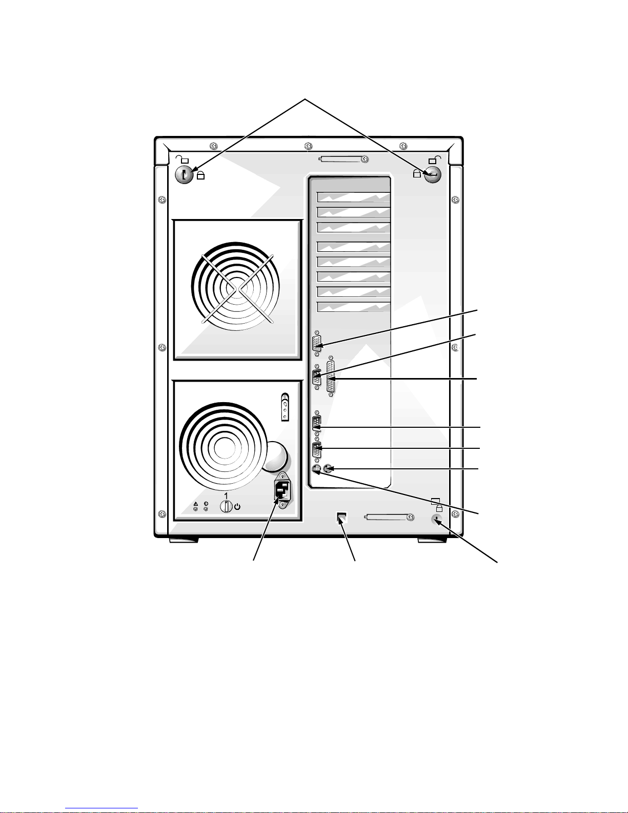
keylocks
video connector
server-management
serial port connector
parallel port connector
AC power receptacle
Figure 2-1. Back Panel Features
SMB connector
serial port 2 connector
serial port 1 connector
mouse connector
keyboard connector
security cable slot
Checking the Basics 2-3
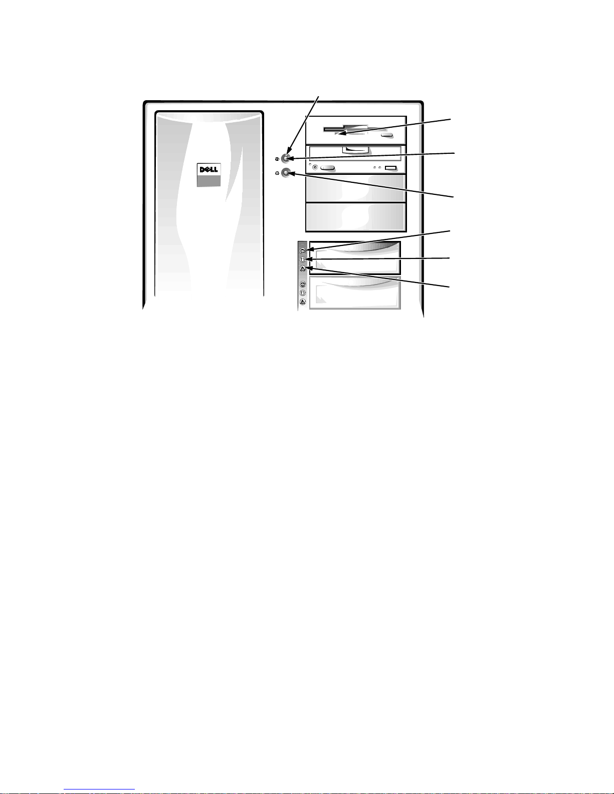
Figure 2-2. Switches and Controls
power indicator
diskette-drive
access indicator
power switch
reset button
hard-disk drive
online indicators (6)
hard-disk drive
activity indicators (6)
hard-disk drive
failure indicators (6)
Complete the following procedure to check all the connections and switches:
1. Turn off the system, includin g any attached
peripherals (such as the monitor, keyboard,
printer, external drives, scanners, and p lotters).
Disconnect all the alternating current (AC) power
cables from their power sources.
2. If the computer is connected to a power strip,
turn the power strip off and then on again.
Is the power strip getting power?
Yes. Go to step 5.
No. Go to step 3.
3. Plug the power strip into another electrical outlet.
Is the power strip getting power?
Yes. The original electrical outlet probably does not
function. Use a different electrical outlet.
No. Go to step 4.
4. Plug a lamp that you know works into the
electrical outlet.
Does the lamp get power?
Yes. The power strip is probably not functioning
properly. Get another power strip.
No. Go to step 5.
5. Reconnect the system to AC power.
Make sure that all connections fit tightly togeth er.
6. Turn on the system.
Is the problem resolved?
Yes. The connections were loose. Y ou have fi xed the
problem.
No. Go to step 7.
7. Is the monitor operating properly?
Yes. Go to step 8.
No. Go to “Troubleshooting the Monitor” in Chapter 6.
8. Is the keyboard operating properly?
2-4 Dell PowerEdge 4200 Sy stems Installation and Troubleshooting Guide
Yes. Go to step 9.
No. Go to “Troubleshooting the Keyboard” in Chap-
ter 6.

9. Is the mouse or printer operating properly?
Yes. Continue with “Look and Listen” found next in
this chapter.
No. Go to “Troubleshooting I/O Ports” in Chapter 6.
L
ook and Listen
Looking at and listening to the system is important in
determining the source of a problem. Look and listen for
the indications described in Table 2-1.
Table 2-1. Boot Routine Indications
Look/Listen for: Action
An error message See Chapter 3, “Messages and Codes.”
Alert messages from the Dell HIP software The server management software has detected a problem inside
the computer. See “Alert Log Messages From the Dell HIP Program” in Chapter 3.
The monitor’s power indicator Most monitors have a power indicator (usually on the front
bezel). If the monitor’s power indicator does not come on, see
“Troubleshooting the Monitor” in Chapter 6.
The keyboard indicators Most keyboards have one or more indicators (usually in the
upper-right corner). Press the <Num Lock> key, the
<Caps Lock> key, or the <Scroll Lock> key to toggle their
respective keyboard indicators on and off. If the indicators do
not light up, see “Troubleshooting the Keyboard” in Chapter 6.
The diskette-drive access indicator The diskette-drive access indicator should quickly flash on and
off when you access data on the diskette drive. If the diskettedrive access indicator does not light up, see “Troubleshooting
the Diskette Drive Subsystem” in Chapter 7.
The hard-disk drive activity indicators The hard-disk drive activity indi cators sho ul d qui ckly flas h on
and off when you access data on the hard-disk drives. On a
system running th e Microsoft
you can test the drive by opening Windows Explorer (in Windows NT 4.0) or the Program Manager (in Windows NT 3.51)
and clicking the icon for drive C. If the hard-disk drive access
indicator does not come on, see “Troubleshooting SCSI Hard-
Disk Drives” in Chapter 7.
A series of beeps See Chapter 3, “Messages and Codes.”
An unfamiliar constant scraping or grinding sound
when you access a drive
Make sure the sound is not caused by the application program
you are running. The s oun d co ul d be cau sed by a hardware mal-
function. See Chapter 11, “Getting Help,” for instructions on
getting technical assistance from Dell.
®
Windows NT® operating system,
Checking the Basics 2-5

Table 2-1. Boot Routine Indications
Look/Listen for: Action
The absence of a familiar sound When you turn on the system, you should hear the hard-d isk
drives spin up, and the system tries to access the boot files from
the hard-disk drive, the diskette drive, or CD-ROM drive. See
Chapter 5, “Running the System Diagnostics.” If the system
does not boot, see Chapter 11, “Getting Help.”
(continued)
If you have not res olved the problem after look ing at and
listening to the computer, continue with the instructions
in “The System Setup Program” found next in this
chapter.
T
he System Setup Program
You can easily correct certain system problems by verifying the correct settings in the System Setup program.
When you boot the system, the system checks the system
configuration information and compares it with the current hardware configuration. If the system hardware
configuration doesn’t match the information recorded by
the System Setup program, an error message may appear
on the screen.
This problem can happen if you changed the system’s
hardware configuration and forgot to run the System
Setup program. To correct this problem, enter the System
Setup program, correct the corresponding System Setup
category, and reboot the system. See Chapter 4, “Using
the System Setup Program,” in the User’s Guide for
detailed instructions on us ing the System Setup program.
T
he EISA Configuration Utility
If you are experiencing problems with the system, you
may have a conflict between the information s tored by
the System Setup program and the Extended IndustryStandard Architecture (EISA) Configuration Utility.
Although the EISA Configuration Utility can read
changes from the System Setup program, changes are not
recorded into EISA configuration memory until you run
the EISA Configuration Utility and save the new information. See Chapter 5, “Using the EISA Configuration
Utility,” in the User’s Guide for detailed instructions on
using the EISA Configu ration Utility and saving new
information.
If after using the EISA Configuration Utility you have
not resolved the problem, see Chapter 5, “Running the
System Diagnostics,” in this guide.
2-6 Dell PowerEdge 4200 Sy stems Installation and Troubleshooting Guide

Chapter 3
Messages and Codes
A
pplication programs, operating systems, and the
computer itself are capable of identifying problems and
alerting you to them. When a problem occurs, a message
may appear on the monitor screen or a beep code may
sound.
Several different types of messages can indicate when the
system is not functioning properly:
•
System messages
•
System beep codes
•
Warning messages
•
Diagnostics messages
S
ystem Messages
System messages alert you to a possible operating problem or to a conflict between the software and hardware. If
you receive a system message, see Table 3-1 for suggestions on resolving any problems indicated by the
message.
NOTE: If you receive a system message that is not listed
in T a ble 3-1, check the documentation for the application
program that is running when the message appears and/
or the operating system documentation for an explanation of the message and recommended action.
•
Alert messages
This chapter describes each type of message and lists the
possible causes and actions you can take to resolve any
problems indicated by a message. To determine what
type of message you have received, read the following
sections.
Messages and Codes 3-1

Table 3-1. System Messages
Message Cause Action
512 MByte memory limit
exceeded - Memory above 512
MBytes disabled.
EISA configuration error
EISA configuration NVRAM bad
Embedded server
management error
Embedded server
management firmware download
failed
The system supports a
maximum of 512 MB o f
memory. Excess memory is not used.
The EISA data in
NVRAM does not
match the installed
EISA expansion cards.
The EISA jumper may
have been accidentally
installed.
The embedded server
management memory
may be temporarily
corrupted.
The embedded server
management memory
may be temporarily
corrupted.
Remove extra DIMMs. See “Removing DIMMs” in Chapter 8.
Verify that any installed EISA expansion cards are properly
seated, and then run the EISA Configuration Utility to verify
that the configuration parameters are correct. See Chapter 5,
“Using the EISA Configuration Utility,” in the User’s Guide.
Remove the EISA jumper, reboot the system, and restore the
EISA configuration parameters. See Chapter 5, “Using the
EISA Configuration Utility,” in the User’s Guide.
Turn off the system to clear the memory, and then restart the
system.
Turn off the system to clear the memory, and then restart the
system.
Incorrect drive
A type - Run
Setup
Incorrect drive
The installed diskette
drive type does not
match the diskette drive
type in CMOS.
Run the System Setup program to correct the diskette drive
type.
B type - Run
Setup
Invalid CPU
speed detected check jumpers
The microprocessorspeed jumper plug may
be absent or installed on
Check the microprocessor speed jumpers. See Table C-1.
the wrong pins.
Invalid CPU speed
detected - Che ck
speed jumpers.
The microprocessor
speed detected is not
valid.
Check the microprocessor speed jumpers. See Table C-1.
System halted.
NOTE: For the full name of an abbreviation or acronym used in this table, see the abbreviation and acronym list.
3-2 Dell PowerEdge 4200 Sy stems Installation and Troubleshooting Guide
 Loading...