

Page 1

Rack Installation Guide
Guide d'installation du rack
Rack-Installationsanleitung
ラック取り付けガイド
Guía de instalación del rack
www.dell.com | support.dell.com
Page 2

Page 3

Rack Installation Guide
Page 4

Notes, Notices, and Cautions
NOTE: A NOTE indicates important information that helps you make better use of your computer.
NOTICE: A NOTICE indicates either potential damage to hardware or loss of data and tells you how to avoid
the problem.
CAUTION: A CAUTION indicates a potential for property damage, personal injury, or death.
____________________
Information in this document is subject to change without notice.
© 2007 Dell Inc. All rights reserved.
Reproduction in any manner whatsoever without the written permission of Dell Inc. is strictly forbidden.
Trademarks used in this text: Dell, the DELL logo, RapidRails, and VersaRails are trademarks of Dell Inc.
Other trademarks and trade names may be used in this document to refer to either the entities claiming the marks and names or their products.
Dell Inc. disclaims any proprietary interest in trademarks and trade names other than its own.
March 2007 P/N TP579 Rev. A00
Page 5

Contents
Safety Instructions . . . . . . . . . . . . . . . . . . . . . . . . . . . . . . . . . 5
SAFETY: Rack Mounting of Systems
. . . . . . . . . . . . . . . . . . . . . 5
General Installation Instructions
Before You Begin
. . . . . . . . . . . . . . . . . . . . . . . . . . . . . . . 6
Important Safety Information
Rack Requirements for VersaRails
Rack Stabilizer Feet
Recommended Tools and Supplies
Rack Kit Contents
Installation Tasks
. . . . . . . . . . . . . . . . . . . . . . . . . . . . . . . 7
. . . . . . . . . . . . . . . . . . . . . . . . . . . . . . . 8
Removing the Rack Doors
Marking the Rack
. . . . . . . . . . . . . . . . . . . . . . . . . . . . . . . . . 9
Configuring the Sliding Rail Assemblies
Installing the Mounting Rails in the Rack
Installing RapidRails Mounting Rails
Installing the VersaRails Mounting Rails
Installing the System in the Rack
Removing the System From the Rack
Installing the Cable-Management Arm
Routing Cables
. . . . . . . . . . . . . . . . . . . . . . . . . . . . . . . . . . 18
. . . . . . . . . . . . . . . . . . . . . . . . . 6
. . . . . . . . . . . . . . . . . . . . . . . . . 6
. . . . . . . . . . . . . . . . . . . . . . 6
. . . . . . . . . . . . . . . . . . . . . . . . . . . . . . 7
. . . . . . . . . . . . . . . . . . . . . . 7
. . . . . . . . . . . . . . . . . . . . . . . . . . . . . 9
. . . . . . . . . . . . . . . . . . . . 11
. . . . . . . . . . . . . . . . . . . . 12
. . . . . . . . . . . . . . . . . . . . 12
. . . . . . . . . . . . . . . . . . 13
. . . . . . . . . . . . . . . . . . . . . . . . 15
. . . . . . . . . . . . . . . . . . . . 16
. . . . . . . . . . . . . . . . . . . . . 17
Attaching the Cable-Management Arm Ramp Assembly
. . . . . . . . . . . . 19
Replacing the Rack Doors
. . . . . . . . . . . . . . . . . . . . . . . . . . . . 21
Contents 3
Page 6

4 Contents
Page 7
Safety Instructions
Use the following safety guidelines to ensure your own personal safety and to help protect your system
and working environment from potential damage. For complete safety and regulatory information, see
the Product Information Guide that shipped with your system. Warranty information might be included
in this document or as a separate document.
SAFETY: Rack Mounting of Systems
Observe the following precautions for rack stability and safety. Also refer to the rack installation
documentation accompanying the system and the rack for specific caution statements and procedures.
Systems are considered to be components in a rack. Thus, "component" refers to any system as well as
to various peripherals or supporting hardware.
CAUTION: Before installing systems in a rack, install front and side stabilizers on stand-alone racks or the front
stabilizer on racks joined to other racks. Failure to install stabilizers accordingly before installing systems in
a rack could cause the rack to tip over, potentially resulting in bodily injury under certain circumstances.
Therefore, always install the stabilizer(s) before installing components in the rack.
After installing system/components in a rack, never pull more than one component out of the rack on its slide
assemblies at one time. The weight of more than one extended component could cause the rack to tip over and
may result in serious injury.
NOTE: Your system is safety-certified as a free-standing unit and as a component for use in a Dell rack cabinet
using the customer rack kit. The installation of your system and rack kit in any other rack cabinet has not been
approved by any safety agencies. It is your responsibility to ensure that the final combination of system and rack
complies with all applicable safety standards and local electric code requirements. Dell disclaims all liability and
warranties in connection with such combinations.
• System rack kits are intended to be installed in a rack by trained service technicians. If you install
the kit in any other rack, be sure that the rack meets the specifications of a Dell rack.
CAUTION: Do not move racks by yourself. Due to the height and weight of the rack, a minimum of two people
should accomplish this task.
• Before working on the rack, make sure that the stabilizers are secured to the rack, extended to the floor,
and that the full weight of the rack rests on the floor. Install front and side stabilizers on a single rack
or front stabilizers for joined multiple racks before working on the rack.
• Always load the rack from the bottom up, and load the heaviest item in the rack first.
• Make sure that the rack is level and stable before extending a component from the rack.
• Use caution when pressing the component rail release latches and sliding a component into or out of
a rack; the slide rails can pinch your fingers.
• Do not overload the AC supply branch circuit that provides power to the rack. The total rack load
should not exceed 80 percent of the branch circuit rating.
• Ensure that proper airflow is provided to components in the rack.
• Do not step on or stand on any component when servicing other components in a rack.
Rack Installation Guide 5
Page 8
General Installation Instructions
This installation guide provides instructions for trained service technicians installing one or more systems in
a rack cabinet. The RapidRails™ configuration can be installed without tools in manufacturer's rack cabinets
that have square holes; the VersaRails™ configuration can be installed in most industry-standard rack
cabinets that have square or round holes. One rack kit is required for each system to be installed in the rack
cabinet.
Before You Begin
Before you begin installing your system in the rack, carefully read "Safety Instructions" on page 5, as well
as the safety instructions found in your Product Information Guide for additional information.
CAUTION: When installing multiple systems in a rack, complete all of the procedures for the current system
before attempting to install the next system.
CAUTION: Rack cabinets can be extremely heavy and move easily on their casters. They do not have brakes. Use
extreme caution while moving the rack cabinet. Retract the leveling feet when relocating the rack cabinet. Avoid
long or steep inclines or ramps where loss of cabinet control may occur. Extend the leveling feet for support and
to prevent the cabinet from rolling.
NOTE: For instructions on installing the system itself, see "Installing the System in the Rack" on page 15.
Important Safety Information
Observe the safety precautions in the following subsections when installing your system in the rack.
CAUTION: You must strictly follow the procedures in this document to protect yourself as well as others who
may be involved. Your system may be very large and heavy and proper preparation and planning are important to
prevent injury to yourself and to others. This precaution becomes increasingly important when systems are
installed high up in the rack.
CAUTION: Do not install rack kit components designed for another system. Use only the rack kit for your system.
Using the rack kit for another system may result in damage to the system and personal injury to yourself and to
others.
Rack Requirements for VersaRails
NOTICE: The VersaRails rack kit is intended to be installed by trained service technicians in a rack that meets the
specifications of American National Standards Institute (ANSI)/Electronic Industries Association (EIA) standard
ANSI/EIA-310-D-92, International Electrotechnical Commission (IEC) 297, and Deutsche Industrie Norm (DIN) 41494.
One rack kit is required for each system that is installed in a rack.
6 Rack Installation Guide
Page 9

Rack Stabilizer Feet
CAUTION: Before installing systems in a rack, install front and side stabilizers on stand-alone racks or the front
stabilizer on racks joined to other racks. Failure to install stabilizers accordingly before installing systems in a
rack could cause the rack to tip over, potentially resulting in bodily injury under certain circumstances.
Therefore, always install the stabilizer(s) before installing components in the rack.
The stabilizer feet help prevent the rack from tipping over. See the documentation provided with the rack
cabinet for instructions on installing and anchoring the stabilizer feet.
Recommended Tools and Supplies
You may need the following items to install the system in a four-post rack cabinet:
• #2 Phillips screwdriver
• Masking tape or a felt-tip pen, for use in marking the mounting holes to be used
Rack Kit Contents
• One pair of slide assemblies
• One cable-management arm
• One left cable-management arm ramp assembly
• One right cable-management arm ramp assembly
• One status indicator cable (if applicable)
• Eight 10-32 x 0.5-inch flange-head Phillips screws
NOTE: The nonmetric screws described in illustrations and in procedural steps are identified by size and number
of threads per inch. For example, a #10 Phillips-head screw with 32 threads per inch is identified as a 10-32 screw.
NOTE: Both the right and left cable-management arm ramp assemblies are illustrated in Figure 1-1. Depending on
the orientation of the cable-management arm (CMA), you will only use one ramp assembly to secure the CMA to
the back of the rack. For more information, see "Attaching the Cable-Management Arm Ramp Assembly"
on page 19.
Rack Installation Guide 7
Page 10

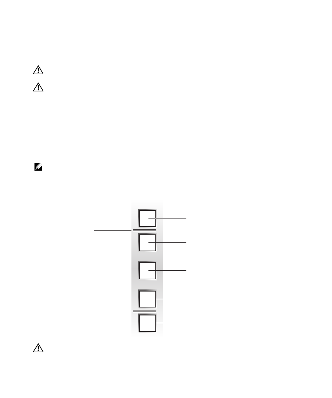
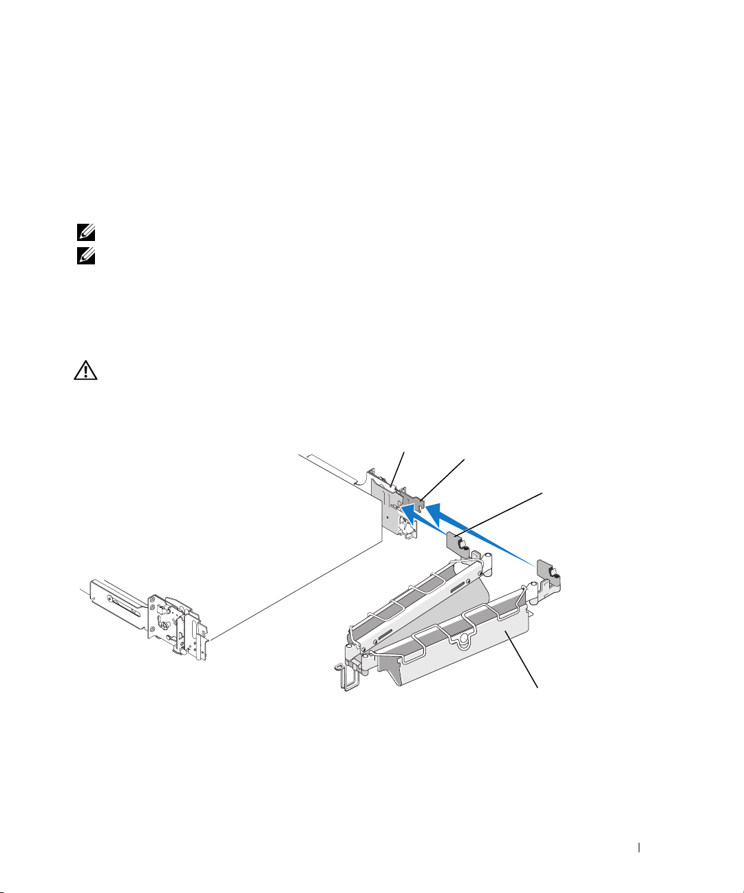
Figure 1-1. Rack Kit Contents
1
6
1 cable-management arm 2 left cable-management arm
ramp assembly
4 slide assemblies 5 10-32 x 0.5-inch flange-head
Phillips screws (8)
2
3
4
5
3 right cable-management arm
ramp assembly
6 status indicator cable
(if applicable)
Installation Tasks
Installing a rack kit involves performing the following tasks (described in detail in subsequent sections)
in their numbered order:
1
Removing the rack doors
2
Marking the rack
3
Configuring the sliding rail assemblies
4
Installing the mounting rails in the rack
• RapidRails installation
• VersaRails installation
5
Installing the system in the rack
6
Installing the cable-management arm
7
Routing cables
8
Attaching the cable-management arm ramp assembly
9
Replacing the rack doors
8 Rack Installation Guide
Page 11
Removing the Rack Doors
See the procedures for removing doors in the documentation provided with your rack cabinet.
CAUTION: Because of the size and weight of the rack cabinet doors, never attempt to remove or install them
by yourself.
CAUTION: Store the doors where they will not injure someone if the doors accidently fall over.
Marking the Rack
For a 2-U system, you must allow 2 U (88 mm, or 3.5 inches) of vertical space for each system you install
in the rack.
Rack cabinets that meet EIA-310 standards have an alternating pattern of three holes per rack unit with
center-to-center hole spacing (beginning at the top hole of a 1-U space) of 15.9 mm, 15.9 mm, and 12.7 mm
(0.625 inch, 0.625 inch, and 0.5 inch) for the front and back vertical rails (see Figure 1-2). Rack cabinets may
have round or square holes.
NOTE: The vertical rails may be marked by horizontal lines and numbers in 1-U increments. If you want, you can
make a note of the number marking on the rack’s vertical rail. It is not necessary to mark or place tape on the rack.
Figure 1-2. One Rack Unit
12.7 mm (0.5 inch)
15.9 mm (0.625 inch)
1 U (44 mm [1.75 inches])
15.9 mm (0.625 inch)
12.7 mm (0.5 inch)
CAUTION: If you are installing more than one system, install the mounting rails so that the first system
is installed in the lowest available position in the rack.
Rack Installation Guide 9
Page 12
To mark the rack, perform the following steps:
1
Place a mark (or tape) on the rack's front vertical rails where you want to locate the bottom of the
system you are installing in the rack. The bottom of each 1-U space is at the middle of the narrowest
metal area between holes (marked with a horizontal line on some rack cabinets—see Figure 1-3).
2
Place a mark 88 mm (3.5 inches) above the original mark you made (or count up three holes in a rack
that meets EIA-310 standards) and mark the rack's front vertical rails with a felt-tipped pen or masking
tape (if you counted holes, place a mark just above the top hole). This mark or piece of tape indicates
where the system's upper edge will be located on the vertical rails (see Figure 1-3).
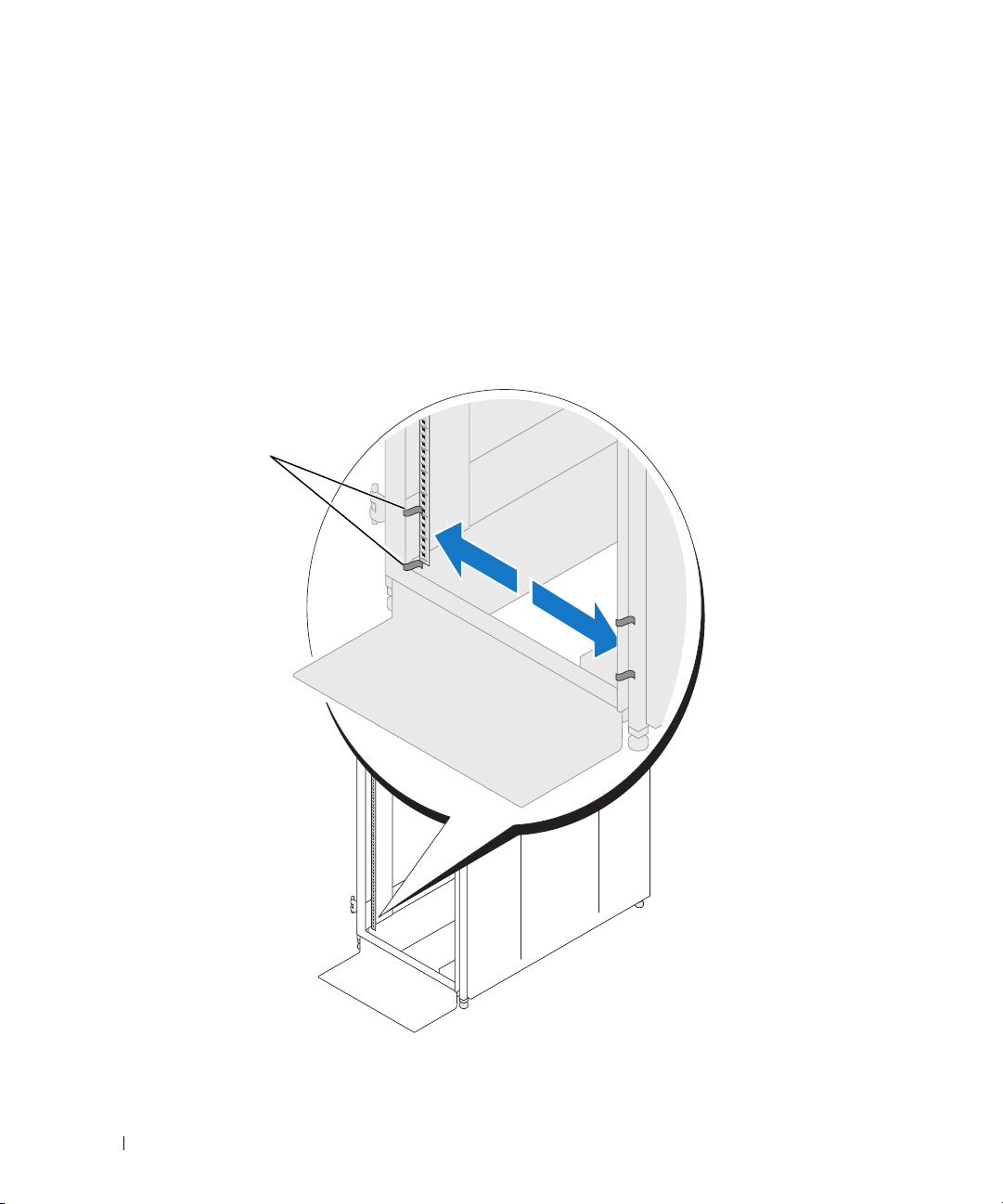
Figure 1-3. Marking the Vertical Rails
1
10 Rack Installation Guide
1 marks on vertical rail (2)
Page 13
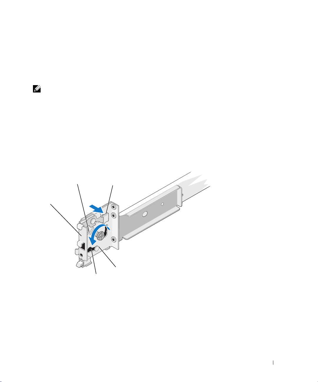
Configuring the Sliding Rail Assemblies
The sliding rail assembly has a rotating mounting bracket at each end of the rail. The position of the
bracket determines whether the rail assembly is used as a RapidRail or a VersaRail. The RapidRail side of
the bracket has a hook and a latch that secure it to the vertical rail. The VersaRail side of the bracket has
three holes and uses screws to attach it to the vertical rail.
NOTE: The rack kit ships with the slide assemblies in the RapidRails configuration.
To change from one type of rail assembly to the other type of rail assembly:
Lift the blue lever on the rotating mounting bracket (see Figure 1-4).
1
2
Rotate the bracket and slide it up off of the two shoulder standoffs.
3
Continue to rotate the bracket 180 degrees until you can set the notches back over the shoulder
standoffs.
4
Rotate the bracket in the opposite direction until the bracket clicks into place.
Figure 1-4. Changing the Position of the Rotating Mounting Bracket
1
5
1 mounting-bracket flange
(RapidRails version shown)
4 shoulder standoffs (2) 5 notches (2)
2
3
4
2 rotating bracket 3 release lever
Rack Installation Guide 11
Page 14
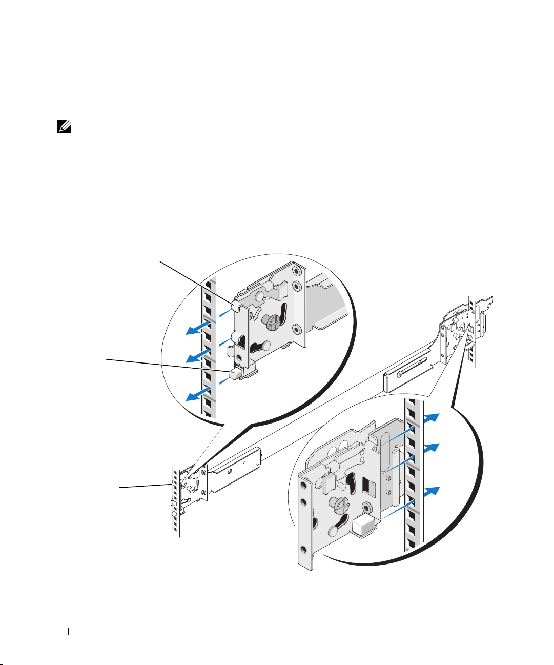
Installing the Mounting Rails in the Rack
Installing RapidRails Mounting Rails
NOTE: Ensure that the rotating mounting brackets on the slide assemblies are in the RapidRail configuration.
See Figure 1-5.
1
At the front of the rack cabinet, position one of the mounting rails so that its mounting-bracket flange
fits between the marks or tape you placed (or numbered locations) on the vertical rails in "Marking the
Rack" on page 9 (see Figure 1-5).
The top mounting hook on the front mounting-bracket flange should enter the top hole between
the marks you made on the vertical rails.
Figure 1-5. Installing RapidRails Mounting Rails
1
2
3
front of rack
1 mounting hooks (4) 2 push buttons (2) 3 mounting rails (2)
12 Rack Installation Guide
Page 15

2
Push the mounting rail forward until the mounting hooks enter their square holes, and then push
down on the mounting-bracket flange until the mounting hooks seat and the push button pops out
and clicks (see Figure 1-5).
3
At the back of the cabinet, pull back on the mounting-bracket flange until the mounting hooks enter
their square holes, and then push down on the flange until the mounting hooks seat and the push
button pops out and clicks.
4
Repeat step 1 through step 3 for the mounting rail on the other side of the rack.
NOTE: Ensure that the mounting rails are mounted at the same vertical position on both sides of the rack.
Installing the VersaRails Mounting Rails
NOTE: Ensure that the rotating mounting brackets on the slide assemblies are in the VersaRail configuration.
See Figure 1-6.
1
At the front of the rack cabinet, position one of the mounting rails so that its mounting-bracket flange
fits between the marks you placed (or numbered locations) on the vertical rails in "Marking the Rack"
on page 9 (see Figure 1-6).
The three holes on the front of the mounting-bracket flange should align with the holes between the
marks you made on the front vertical rail.
2
Install two 10-32 x 0.5-inch flange-head Phillips screws in the upper and lower holes in the mountingbracket flange to secure the mounting rail to the front vertical rail.
3
At the back of the cabinet, pull back on the mounting-bracket flange until the mounting holes align
with their respective holes on the back vertical rail.
4
Install two 10-32 x 0.5-inch flange-head Phillips screws in the upper and lower holes in the mountingbracket flange to secure the mounting rail to the back vertical rail.
5
Repeat step 1 through step 4 for the mounting rail on the other side of the rack.
NOTE: Ensure that the mounting rails are mounted at the same position on the vertical rails on each side
of the rack.
Rack Installation Guide 13
Page 16
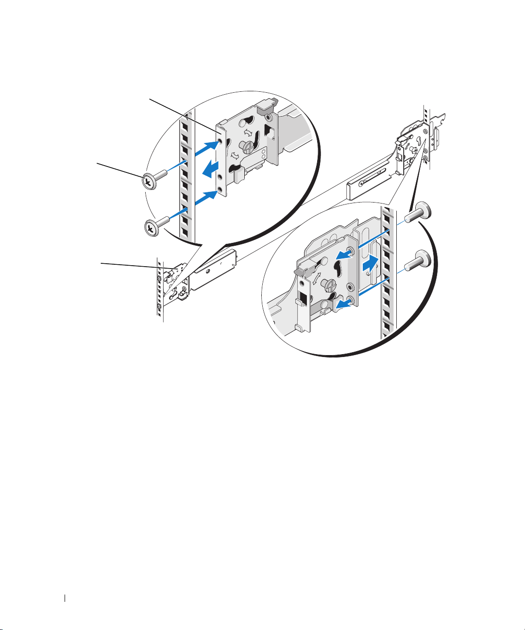
Figure 1-6. Installing VersaRails Mounting Rails
1
2
3
front of rack
1 mounting-bracket flange 2 10-32 x 0.5-inch flange-head Phillips
14 Rack Installation Guide
3 mounting rails (2)
screws (4 per mounting rail)
Page 17

Installing the System in the Rack
CAUTION: If you are installing more than one system, install the first system in the lowest available position
in the rack.
CAUTION: Because of the size and weight of the system, never attempt to install the system in the mounting rails
by yourself.
1
Pull the two inner slide rails out of the rack until they lock in the fully extended position.
2
Lift the system into position above the extended slides.
The three shoulder screws on the sides of the system fit into the corresponding J-slots (see detail
on Figure 1-7) on the inner slide assemblies.
3
Lower the back of the system while aligning the back shoulder screws on the sides of the system
with the back J-slots on the slide assemblies.
4
Engage the back shoulder screws into their respective J-slots.
5
Lower the front of the system and fit the middle and front shoulder screws into the J-slots in the slide
assemblies.
The system release latch at the front of the inner slide rail will snap back as the shoulder screw passes
into the front slot. Use this system release latch when you wish to remove the system from the slide
assemblies.
6
Press the slide-release latch on the outside of each inner slide, then push the system into the rack.
7
Install the cable-management arm. See "Installing the Cable-Management Arm" on page 17.
8
Tighten the thumbscrews on the rack front panel to secure the slide assemblies to the rack.
Rack Installation Guide 15
Page 18
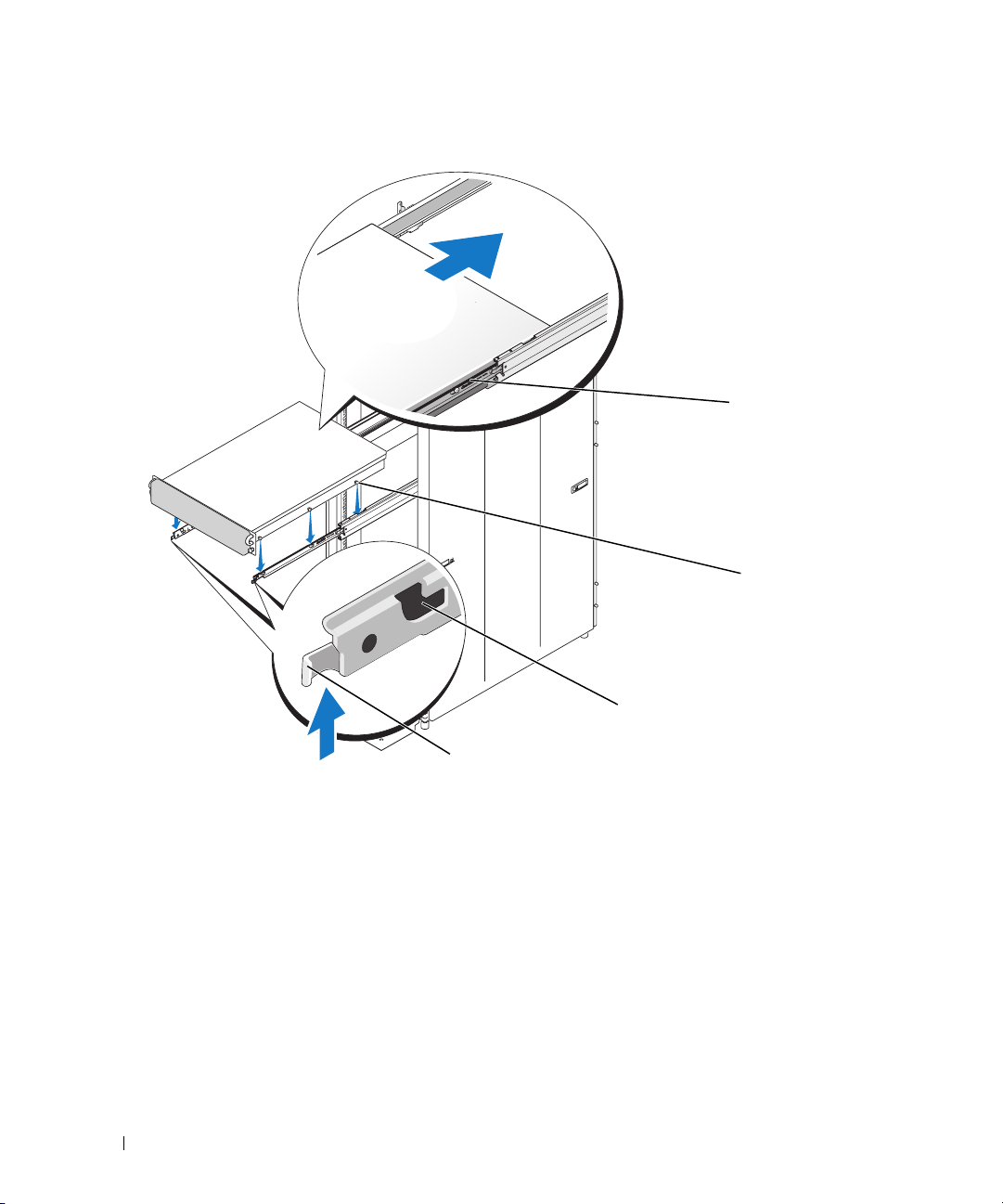
Figure 1-7. Installing the System in the Rack
1
2
4
1 slide-release latch 2 shoulder screws (6) 3 J slots (6)
4 front release latch
Removing the System From the Rack
To remove the system from the rack, perform the following procedure:
1
Turn off the system and attached peripherals, and disconnect the system from the electrical outlet.
2
Remove the I/O cable connectors and power cable connectors from their respective connectors
on the system back panel.
3
Loosen the thumbscrews on each side of the front chassis panel that secures the system to the rack.
16 Rack Installation Guide
3
Page 19
4
Pull the system out of the rack until it stops because of the safety catch.
5
Pull up on the front release latch on each rail to disengage the safety catch (see Figure 1-7) and slide
the system forward.
6
Pull the system completely out of the rack.
Installing the Cable-Management Arm
NOTE: You can attach the
NOTE: Attach the
management arm.
1
Fit the latch on the front end of the cable-management arm onto the bracket on the end of the
cable-management arm to either side of the rack cabinet.
cable-management arm ramp assembly to the side opposite of where you attach the cable-
mounting rail until the latch clicks (see Figure 1-8).
2
Fit the latch on the unattached end of the cable-management arm onto the bracket on the end of the
slide assembly until the latch clicks (see Figure 1-8).
CAUTION: Both ends of the cable-management arm must be connected before you begin routing the system
.
cables
Figure 1-8. Installing the Cable-Management Arm
1
back of system
2
3
1 mounting rails (2) 2 brackets (2)
3 latches (2) 4 cable-management arm
4
Rack Installation Guide 17
Page 20
Routing Cables
1
Open the wire cable basket on the top of the cable-management arm
within the arms (see Figure 1-9).
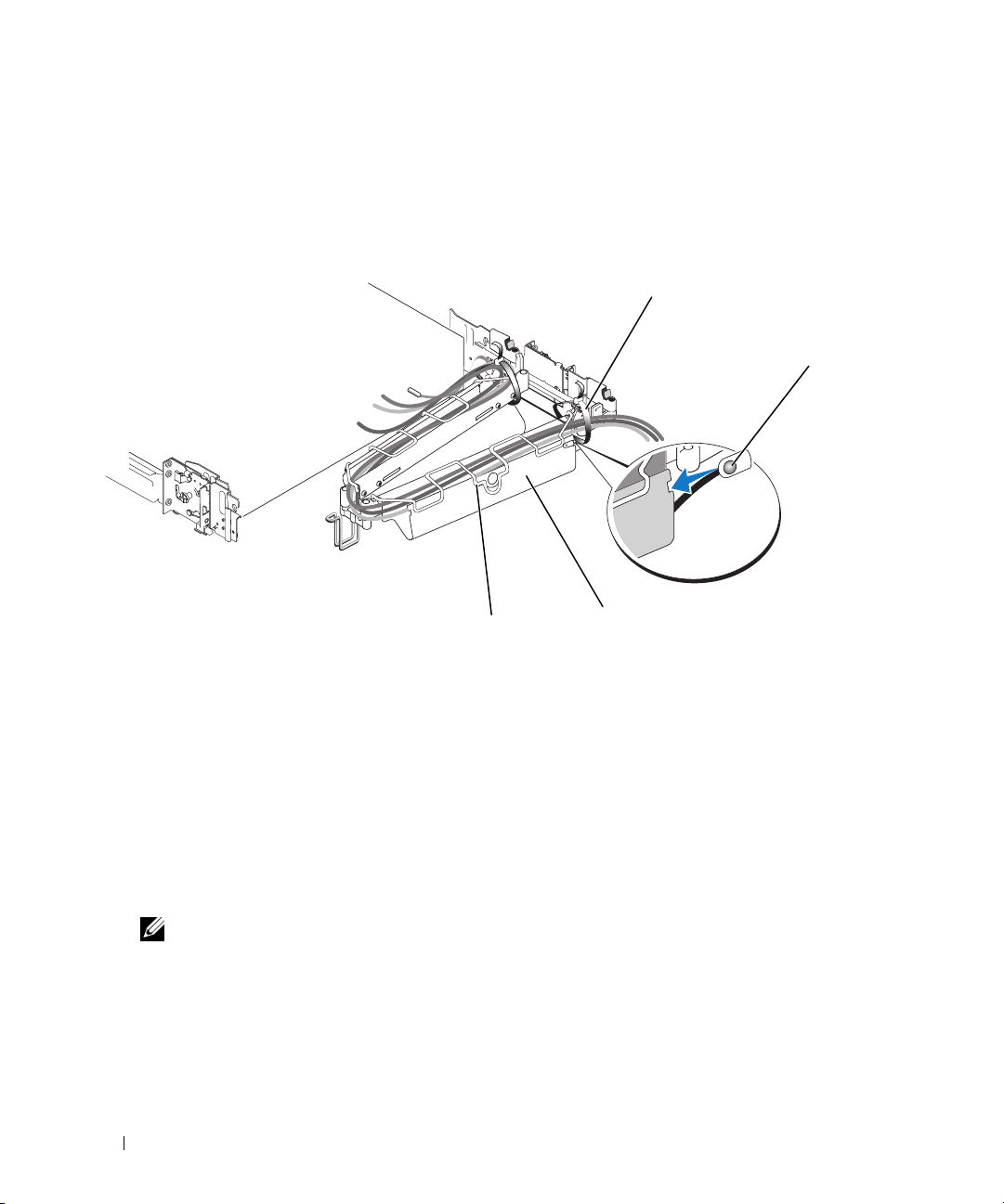
Figure 1-9. Routing Cables on the Cable-Management Arm
, to
enable cables to be routed
1
2
4
1 tie wraps (2) 2 system status-indicator cable connector
3 cable-management arm 4 wire cable basket
2
If applicable, connect the system status-indicator cable to its connector on the system back panel.
Route the system status-indicator cable through the cable-management arm, and press the LED end
into the slot on the end of the cable-management arm until it snaps into place.
3
Attach the I/O cable connectors and power cable connectors to their respective connectors on the
system back panel.
For details on cable connections, see your system’s Getting Started Guide or Hardware Owner’s
Manual.
NOTE: Use the retainer brackets on the back of the power supplies to provide strain relief for the power
cables.
4 Route the cables along the bend in the cable-management arm.
Adjust the cable slack as needed at the hinge position and secure the cables with the tie wraps
5
(see Figure 1-9).
6
Close the cable basket.
18 Rack Installation Guide
3
Page 21
7 Slide the system in and out of the rack to verify that the cables are routed correctly and do not bind,
stretch, or interfere with the movement of the cable-management arm. Adjust the cable positioning
inside the cable-management arm as needed.
NOTE: If you pull the system out to its furthest extension, the slide assemblies will lock in the extended
position. To release the lock, press the slide release latch on the side of each slide and then slide the system
into the rack.
8
When you are satisfied that the cables are routed correctly, push the system fully into the rack.
Attaching the Cable-Management Arm Ramp Assembly
The cable-management arm ramp assembly guides the cable-management arm into a stable,
level position. To attach the cable-management arm ramp assembly:
1
Select only one ramp assembly, depending on the orientation of the cable-management arm.
a
If the cable-management arm is attached on the right side of the rack (as shown in Figure 1-11),
attach the left cable-management arm ramp assembly to the rack (see Figure 1-10).
b
If the cable-management arm is attached on the left side of the rack, attach the right cablemanagement arm ramp assembly to the rack (see Figure 1-10).
CAUTION: The cable-management arm ramp assembly must be installed to prevent long-term sagging
of the cable-management arm.
NOTE: Ensure that you use the
the center of the rack (see Figure 1-10).
cable-management arm ramp assembly with the metal ramp facing toward
NOTE: The orientation shown in
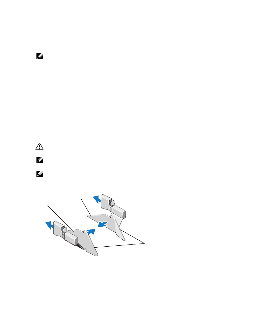
Figure 1-10. Orientation for the Left or Right Cable-Management Arm Ramp Assembly
2
1
1 left cable-management arm
ramp assembly
Figure 1-10 presumes you are facing the back of the system
3
2 right cable-management arm
ramp assembly
.
3 metal ramp
Rack Installation Guide 19
Page 22
2
1
Fit the latch of the ramp assembly on the ramp assembly bracket, located on the opposite side of
the rack from where you attached the cable-management arm (see Figure 1-11).
3 To slide the cable-management arm into place:
a
Locate the ramp assembly wireform guide at the bend of the cable-management arm.
b
Lift and slide the ramp assembly wireform guide up the ramp, stopping at the ramp assembly
seating catch.
c
If you have selected the correct ramp assembly, the wireform guide will seat correctly in the catch
at the top of the ramp assembly each time the system is cycled in the rack. Figure 1-11 shows
the left ramp assembly installed with the cable-management arm attached on the right.
To disengage the cable-management arm ramp assembly, press the ramp assembly release button on
the ramp assembly latch and pull the ramp assembly off the bracket (see
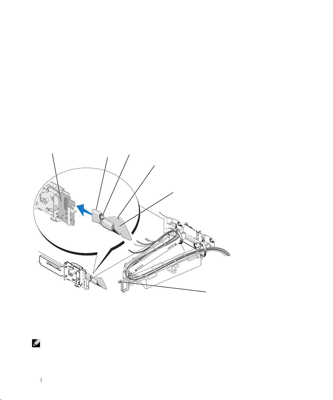
Figure 1-11. Installing the Cable-Management Arm Ramp Assembly
2
3
4
5
Figure 1-11).
1 ramp assembly bracket 2 cable-management arm ramp
assembly latch
4 ramp assembly seating catch 5 left cable-management arm
ramp assembly
NOTE: In Figure 1-11, the cable-management arm is attached on the right side of the rack and the left cable-
management arm ramp assembly is attached to the left side of the rack. Conversely, if you attach the cablemanagement arm on the left side of the rack, attach the right cable-management arm ramp assembly to the right
side of the rack.
20 Rack Installation Guide
6
3 ramp assembly release button
6 ramp assembly wireform
guide
Page 23

Replacing the Rack Doors
See the procedures for replacing doors in the documentation provided with your rack.
CAUTION: Because of the size and weight of the rack cabinet doors, never attempt to remove or install them
by yourself.
Rack Installation Guide 21
Page 24

22 Rack Installation Guide
Page 25

Guide d'installation du rack
Page 26

Remarques, avis et précautions
REMARQUE : une REMARQUE indique des informations importantes qui peuvent vous aider à mieux utiliser
votre ordinateur.
AVIS : un AVIS vous avertit d'un risque de dommage matériel ou de perte de données et vous indique comment éviter
le problème.
PRÉCAUTION : une PRÉCAUTION indique un risque potentiel d'endommagement du matériel, de blessure corporelle
ou de mort.
____________________
Les informations contenues dans ce document peuvent être modifiées sans préavis.
© 2007 Dell Inc. Tous droits réservés.
La reproduction de ce document de quelque manière que ce soit sans l'autorisation écrite de Dell Inc. est strictement interdite.
Marques utilisées dans ce document : Dell, le logo DELL, RapidRails et VersaRails sont des marques de Dell Inc.
Tous les autres noms de marques et marques commerciales utilisés dans ce document se rapportent aux sociétés propriétaires de ces marques et de
ces noms ou à leurs produits. Dell Inc. décline tout intérêt dans l'utilisation des marques déposées et des noms de marques ne lui appartenant pas.
Mars 2007 P/N TP579 Rev. A00
Page 27

Sommaire
Consignes de sécurité . . . . . . . . . . . . . . . . . . . . . . . . . . . . . . 27
SÉCURITÉ : montage en rack des systèmes
. . . . . . . . . . . . . . . . 27
Consignes générales d'installation
Avant de commencer
. . . . . . . . . . . . . . . . . . . . . . . . . . . . 28
Informations importantes concernant la sécurité
Spécifications de rack requises pour les rails VersaRails
Pieds stabilisateurs du rack
Outils et fournitures recommandés
Contenu du kit de rack
Tâches d'installation
Retrait des portes du rack
Marquage du rack
. . . . . . . . . . . . . . . . . . . . . . . . . . . . 30
. . . . . . . . . . . . . . . . . . . . . . . . . . . . 31
. . . . . . . . . . . . . . . . . . . . . . . . . . . . . . . . 31
Configuration des assemblages à glissière
Installation des rails de montage dans le rack
Installation des rails de montage RapidRails
Installation des rails de montage VersaRails
Installation du système dans le rack
Retrait d'un système installé dans le rack
Installation du bras de gestion des câbles
Acheminement des câbles
. . . . . . . . . . . . . . . . . . . . . . . . . . . . 41
. . . . . . . . . . . . . . . . . . . . . . . 28
. . . . . . . . . . . . . 28
. . . . . . . . . 29
. . . . . . . . . . . . . . . . . . . . . . . . 29
. . . . . . . . . . . . . . . . . . . . . 29
. . . . . . . . . . . . . . . . . . . . . . . . . . . 29
. . . . . . . . . . . . . . . . . . . 33
. . . . . . . . . . . . . . . . . 34
. . . . . . . . . . . . . . . . 34
. . . . . . . . . . . . . . . . 35
. . . . . . . . . . . . . . . . . . . . . . 37
. . . . . . . . . . . . . . . . . 39
. . . . . . . . . . . . . . . . . . . 39
Installation de l'assemblage de fixation du bras de gestion des câbles
. . . . 42
Remise en place des portes du rack
. . . . . . . . . . . . . . . . . . . . . . 44
Sommaire 25
Page 28

26 Sommaire
Page 29

Consignes de sécurité
Respectez les consignes de sécurité de ce guide pour assurer votre sécurité personnelle et pour contribuer
à protéger votre système et votre environnement de travail de dommages potentiels. Pour obtenir
toutes les informations concernant la sécurité et les réglementations, consultez le document Product
Information Guide (Guide d'informations sur le produit) fourni avec le système. Les informations sur
la garantie se trouvent soit dans ce document, soit à part.
SÉCURITÉ : montage en rack des systèmes
Pour garantir la stabilité du rack, ainsi que votre sécurité, respectez les précautions suivantes.
Reportez-vous également à la documentation accompagnant le système et le rack pour connaître
les mises en garde et les procédures spécifiques.
Les systèmes sont considérés comme étant les composants d'un rack. Le terme “composant” fait donc
référence à un système mais aussi aux différents périphériques ou matériels associés.
PRÉCAUTION : avant d'installer des systèmes dans un rack autonome, installez d'abord les pieds stabilisateurs
avant et latéraux. Pour plusieurs racks associés, installez d'abord les pieds stabilisateurs avant. L'installation
de systèmes dans un rack non équipé de pieds stabilisateurs peut provoquer son basculement et entraîner des
blessures. Installez toujours les pieds stabilisateurs du rack avant d'ajouter des composants dans celui-ci.
Après avoir installé un système ou des composants dans un rack, ne faites jamais coulisser hors du rack plus
d'un composant à la fois. Le poids de plusieurs composants sortis du rack risquerait de le faire basculer et de
blesser quelqu'un gravement.
REMARQUE : le système est certifié sur le plan de la sécurité en tant qu'unité autonome et en tant que composant
destiné à être utilisé dans un rack Dell, à l'aide du kit de rack client. L'installation du système et du kit d'installation
en rack dans une autre armoire n'a reçu aucune homologation des organismes de certification de la sécurité.
Il vous incombe de veiller à ce que la combinaison finale système et rack soit conforme à toutes les normes de
sécurité en vigueur, ainsi qu'aux normes électriques locales. Dell décline toute responsabilité et toutes garanties
liées à ce type de combinaisons.
• Les kits de rack doivent être installés par des techniciens de maintenance qualifiés. Si vous installez ce
kit dans un autre rack, assurez-vous que ce dernier possède les mêmes spécifications qu'un rack Dell.
PRÉCAUTION : ne déplacez pas de rack sans aide. En raison de la hauteur et du poids du rack, cette tâche doit
être réalisée par deux personnes au minimum.
• Avant de travailler sur le rack, vérifiez que les pieds stabilisateurs sont fixés au rack, qu'ils touchent le
sol et que tout le poids du rack repose sur le sol. Avant d'intervenir sur un rack isolé, installez d'abord
les pieds stabilisateurs avant et latéraux. Pour plusieurs racks associés, installez d'abord les pieds
stabilisateurs avant.
• Chargez le rack du bas vers le haut, en plaçant toujours l'élément le plus lourd en premier.
• Assurez-vous que le rack est d'aplomb et stable avant de tirer un composant hors de son compartiment.
• Agissez avec précaution lorsque vous appuyez sur les loquets d'éjection des rails pour insérer ou retirer
un composant. Veillez notamment à ne pas coincer vos doigts dans les rails coulissants.
Guide d'installation du rack 27
Page 30
• Ne surchargez pas le circuit d'alimentation secteur du rack. La consommation totale du rack ne doit
pas dépasser 80 % de la capacité du circuit.
• Assurez-vous que les éléments installés dans le rack sont suffisamment ventilés.
• Ne montez pas sur un composant lorsque vous intervenez sur d'autres composants du rack.
Consignes générales d'installation
Ce guide d'installation s'adresse à des techniciens de maintenance qualifiés. Il contient les instructions
relatives à l'installation d'un ou de plusieurs systèmes dans un rack. La configuration RapidRails™ peut être
installée sans outils dans tous les racks du fabricant dotés de trous carrés ; la configuration VersaRails™ peut
être installée dans la plupart des racks standard équipés de trous carrés ou ronds. Un kit d'installation est
nécessaire pour chaque système.
Avant de commencer
Avant de commencer à installer le système dans le rack, lisez attentivement la section “Consignes de
sécurité” à la page 27, ainsi que les consignes de sécurité figurant dans le document Product Information
Guide (Guide d'informations sur le produit) pour plus d'informations.
PRÉCAUTION : si vous installez plusieurs systèmes dans un rack, terminez toutes les opérations requises
sur le système en cours d'installation avant de passer au suivant.
PRÉCAUTION : les racks peuvent être extrêmement lourds, mais se déplacent assez facilement sur leurs
roulettes. Cependant, les roulettes ne possèdent pas de système de freinage. Procédez avec la plus grande
prudence pour déplacer un rack. Rentrez ses pieds réglables lorsque vous le changez d'emplacement. Évitez de
déplacer le rack le long de rampes ou de plans inclinés trop longs ou trop abrupts, sur lesquels l'armoire pourrait
vous échapper. Ressortez les pieds réglables lorsque l'armoire doit être soutenue ou pour lui éviter de glisser sur
ses roulettes.
REMARQUE : pour plus d'informations sur l'installation du système proprement dit, voir “Installation du système
dans le rack” à la page 37.
Informations importantes concernant la sécurité
Respectez les précautions décrites dans les sous-sections suivantes lors de l'installation du système
dans le rack.
PRÉCAUTION : vous devez respecter à la lettre les procédures de ce document afin de garantir votre propre
protection ainsi que celle d'autrui. Le système peut être très lourd et volumineux. Une préparation et une
planification adéquates sont donc importantes afin d'éviter tout risque de blessure pour vous-même ou autrui.
Ces précautions sont d'autant plus importantes lorsque les systèmes sont installés en hauteur.
PRÉCAUTION : n'installez pas de kits prévus pour un autre système. Sinon, vous risquez d'endommager
le système et de vous blesser ou de blesser une autre personne.
28 Guide d'installation du rack
Page 31

Spécifications de rack requises pour les rails VersaRails
AVIS : le kit VersaRails est prévu pour être installé par des techniciens de maintenance qualifiés dans un rack
conforme aux spécifications des organismes suivants : American National Standards Institute (ANSI)/Electronic
Industries Association (EIA) standard ANSI/EIA-310-D-92, International Electrotechnical Commission (IEC) 297
et Deutsche Industrie Norm (DIN) 41494. Un kit est nécessaire pour chaque système installé dans un rack.
Pieds stabilisateurs du rack
PRÉCAUTION : avant d'installer des systèmes dans un rack autonome, installez d'abord les pieds stabilisateurs
avant et latéraux. Pour plusieurs racks associés, installez d'abord les pieds stabilisateurs avant. L'installation
de systèmes dans un rack non équipé de pieds stabilisateurs peut provoquer son basculement et entraîner des
blessures. Installez toujours les pieds stabilisateurs du rack avant d'ajouter des composants dans celui-ci.
Les pieds stabilisateurs évitent au rack de basculer. Consultez la documentation fournie avec le rack
pour savoir comment installer et fixer les pieds stabilisateurs.
Outils et fournitures recommandés
Les outils et fournitures suivants peuvent être nécessaires pour installer le système dans un rack
à quatre montants :
• Tournevis cruciforme n° 2
• Bande adhésive ou stylo feutre, pour marquer les trous de montage à utiliser
Contenu du kit de rack
• Une paire d'assemblages à glissière
• Un bras de gestion des câbles
• Un assemblage de fixation pour le bras de gestion des câbles (gauche)
• Un assemblage de fixation pour le bras de gestion des câbles (droit)
• Un câble de voyant d'état (le cas échéant)
• Huit vis à tête cruciforme 10-32 x 0,5 pouce
REMARQUE : les vis au pas non métrique décrites dans les illustrations et dans les procédures sont identifiées
par la taille et le nombre de filets par pouce. Par exemple, une vis à tête cruciforme n° 10 avec 32 filets par pouce
est désignée par l'appellation “vis 10-32”.
REMARQUE : les deux assemblages de fixation du bras de gestion des câbles (gauche et droit) sont représentés
à la figure 1-1. Pour attacher le bras de gestion des câbles à l'arrière du rack, vous n'avez besoin que d'un seul
assemblage de fixation. L'assemblage à utiliser dépend du sens dans lequel le bras de gestion des câbles est
installé. Pour plus d'informations, voir “Installation de l'assemblage de fixation du bras de gestion des câbles”
àlapage42.
Guide d'installation du rack 29
Page 32

Figure 1-1. Contenu du kit de rack
1
6
1 Bras de gestion des câbles 2 Assemblage de fixation du
4 Assemblages à glissière 5 Vis cruciformes à tête plate
2
bras de gestion des câbles
(gauche)
10-32 x 0,5 pouce (8)
3
4
5
3 Assemblage de fixation du
bras de gestion des câbles
(droit)
6 Câble de voyant d'état
(le cas échéant)
Tâches d'installation
Pour installer un kit, vous devez effectuer dans l'ordre indiqué les tâches suivantes, qui sont décrites
plus loin dans ce guide :
1
Retrait des portes du rack
2
Marquage du rack
3
Configuration des assemblages à glissière
4
Installation des rails de montage dans le rack
• Installation du kit RapidRails
• Installation du kit VersaRails
5
Installation du système dans le rack
6
Installation du bras de gestion des câbles
7
Acheminement des câbles
8
Installation de l'assemblage de fixation du bras de gestion des câbles
9
Remise en place des portes du rack
30 Guide d'installation du rack
Page 33

Retrait des portes du rack
Pour savoir comment retirer les portes du rack, reportez-vous à la documentation fournie avec ce dernier.
PRÉCAUTION : compte tenu de leur poids et de leur taille, ne retirez ou n'installez jamais les portes sans
l'assistance d'une autre personne.
PRÉCAUTION : placez les portes dans un endroit sûr où elles ne risquent pas de tomber accidentellement
et de blesser quelqu'un.
Marquage du rack
Pour un système de 2 U, vous devez compter un espace vertical de 88 mm ou 3,5 pouces pour
chaque système installé dans le rack.
Les racks conformes aux normes EIA-310 comportent des séries alternées de trois trous par unité.
L'espacement entre les trous, mesuré de centre à centre (en commençant par le trou supérieur) est
respectivement de 15,9 mm, 15,9 mm et 12,7 mm (0,625 pouce, 0,625 pouce et 0,5 pouce) pour les rails
verticaux avant et arrière (voir la figure 1-2). Les racks peuvent comporter des trous ronds ou carrés.
REMARQUE : les rails verticaux peuvent être marqués par des lignes horizontales et des chiffres progressant
par incréments de 1 U. Si vous le souhaitez, vous pouvez noter le numéro figurant sur le rail vertical du rack.
Dans ce cas, il n'est pas nécessaire de marquer le rack ni d'y apposer un morceau de bande adhésive.
Figure 1-2. Unité de rack
12,7 mm
15,9 mm
1U (44 mm)
15,9 mm
12,7 mm
PRÉCAUTION : si vous installez plusieurs systèmes, placez les rails de montage de façon que le premier
système soit disposé le plus bas possible dans le rack.
Guide d'installation du rack 31
Page 34

Pour marquer le rack, procédez comme suit :
1
Placez une marque (ou de la bande adhésive) sur les rails verticaux avant du rack, à l'endroit
correspondant au bas du système à installer. Le bas de chaque espace de 1 U se trouve au milieu de
la zone métallique la plus étroite entre les trous (repérée par une ligne horizontale sur certains racks ;
voir la figure 1-3).
2
Placez une marque à environ 88 mm (3,5 pouces) au-dessus de la marque que vous avez faite au départ
(ou remontez de 3 trous dans les racks conformes à la norme EIA-310), puis marquez les rails verticaux
du rack avec un stylo feutre ou de la bande adhésive (si vous avez compté les trous, placez une marque
juste au-dessus du trou supérieur). Cette marque ou ce morceau de bande adhésive indique
l'emplacement du rebord supérieur du système sur les rails verticaux (voir la figure 1-3).
Figure 1-3. Marquage des rails verticaux
1
32 Guide d'installation du rack
1 Marques sur le rail vertical (2)
Page 35

Configuration des assemblages à glissière
Les assemblages à glissière disposent d'un support de montage rotatif situé à chacune de leurs
extrémités. La position de ce support détermine si l'assemblage est utilisé en mode RapidRails ou
VersaRails. Le côté RapidRails du support est équipé d'un crochet et d'un loquet qui le fixe au rail
vertical. Le côté VersaRails du support comporte trois trous. Le support est alors fixé au rail vertical
par des vis.
REMARQUE : les assemblages à glissière fournis avec le kit sont montés selon la configuration RapidRails.
Pour passer d'une configuration à l'autre, procédez comme suit :
1
Relevez le levier bleu du support de montage rotatif (voir la figure 1-4).
2
Faites pivoter le support puis faites-le glisser vers le haut pour le dégager des deux dispositifs
à épaulement.
3
Continuez de faire pivoter le support à 180 degrés jusqu'à ce que vous puissiez de nouveau placer
les encoches sur les dispositifs à épaulement.
4
Faites pivoter le support dans la direction opposée jusqu'à ce qu'il s'enclenche.
Figure 1-4. Changement de la position du support de montage rotatif
1
5
1 Collerette du support de
montage (configuration
RapidRails)
4 Dispositifs à épaulement (2) 5 Encoches (2)
2
3
4
2 Support rotatif 3 Levier d'éjection
Guide d'installation du rack 33
Page 36

Installation des rails de montage dans le rack
Installation des rails de montage RapidRails
REMARQUE : vérifiez que les supports de montage rotatifs des assemblages à glissière sont montés selon
la configuration RapidRails. Voir la figure 1-5.
1
À l'avant du rack, positionnez l'un des rails de façon que la collerette du support de montage s'insère
entre les marques que vous avez faites (section “Marquage du rack” à la page 31), les morceaux
de bande adhésive ou les emplacements numérotés sur les rails verticaux. Voir la figure 1-5.
Le crochet de fixation supérieur situé sur la collerette avant du support de montage doit pénétrer
dans le trou supérieur qui se trouve entre les marques faites sur les rails verticaux.
Figure 1-5. Installation des rails de montage RapidRails
1
2
3
Avant du rack
1 Crochets de fixation (4) 2 Boutons-poussoirs (2) 3 Rails de montage (2)
34 Guide d'installation du rack
Page 37

2
Poussez le rail vers l'avant jusqu'à ce que les crochets de fixation soient positionnés dans les trous
carrés, puis appuyez sur la collerette de montage jusqu'à ce que les crochets se mettent en place et
que le bouton-poussoir ressorte avec un déclic (voir la figure 1-5).
3
À l'arrière de l'armoire, tirez la collerette de montage vers l'arrière jusqu'à ce que les crochets soient
positionnés dans les trous carrés, puis appuyez sur la collerette jusqu'à ce que les crochets se mettent
en place et que le bouton-poussoir ressorte avec un déclic.
4
Recommencez la procédure de l'étape 1 à l'étape 3, pour le rail de montage situé de l'autre côté
du rack.
REMARQUE : vérifiez que les rails de montage sont montés à la même position verticale de chaque côté
du rack.
Installation des rails de montage VersaRails
REMARQUE : vérifiez que les supports de montage rotatifs des assemblages à glissière sont montés selon
la configuration VersaRails. Voir la figure 1-6.
1
À l'avant du rack, positionnez l'un des rails de façon que la collerette du support de montage s'insère
entre les marques que vous avez faites (section “Marquage du rack” à la page 31), les morceaux de
bande adhésive ou les emplacements numérotés sur les rails verticaux. Voir la figure 1-6.
Les trois trous situés à l'avant de la collerette du support de montage doivent s'aligner avec ceux
qui se trouvent entre les marques que vous avez faites sur le rail vertical avant.
2
Insérez deux vis cruciformes 10-32 x 0,5 pouce dans les trous supérieur et inférieur de la collerette
du support de montage pour fixer le rail de montage sur le rail vertical avant.
3
À l'arrière de l'armoire, tirez sur la collerette du support de montage jusqu'à ce que les trous de
montage s'alignent avec les trous correspondants du rail vertical arrière.
4
Insérez deux vis cruciformes 10-32 x 0,5 pouce dans les trous supérieur et inférieur de la collerette
du support de montage pour fixer le rail de montage sur le rail vertical arrière.
5
Recommencez la procédure de l'étape 1 à l'étape 4, pour le rail de montage situé de l'autre côté
du rack.
REMARQUE :
vérifiez que les rails sont montés à la même hauteur sur les rails verticaux de chaque côté du rack.
Guide d'installation du rack 35
Page 38

Figure 1-6. Installation des rails de montage VersaRails
1
2
3
Avant du rack
1 Collerette du support de montage 2 Vis cruciformes à tête plate
36 Guide d'installation du rack
3 Rails de montage (2)
10-32 x 0,5 pouce (4 par rail
de montage)
Page 39

Installation du système dans le rack
PRÉCAUTION : si vous installez plusieurs systèmes, installez le premier le plus bas possible dans le rack.
PRÉCAUTION : en raison de la taille et du poids du système, ne tentez jamais de l'installer seul dans les rails
de montage.
1
Tirez les deux rails coulissants intérieurs hors du rack jusqu'à ce qu'ils bloquent sur la butée.
2
Soulevez le système pour le placer au dessus des rails coulissants.
Les trois vis à épaulement situées de chaque côté du système s'emboîtent dans les fentes en forme de J
qui se trouvent sur les assemblages à glissière intérieurs (voir la figure 1-7).
3
Inclinez le système vers l'arrière tout en alignant les vis à épaulement arrière situées sur les côtés
du système avec les fentes en J situées à l'arrière des assemblages à glissière.
4
Emboîtez les vis à épaulement arrière dans les fentes correspondantes.
5
Abaissez l'avant du système jusqu'à ce que les vis à épaulement avant et centrale s'emboîtent dans
les fentes en J.
Le loquet d'éjection du système situé à l'avant du rail coulissant intérieur s'enclenche lorsque la vis
à épaulement s'insère dans la fente avant. Utilisez ce loquet pour retirer le système des assemblages
à glissière.
6
Appuyez sur le loquet d'éjection situé à l'extérieur de chaque rail coulissant intérieur, puis poussez
le système dans le rack.
7
Installez le bras de gestion des câbles. Voir “Installation du bras de gestion des câbles” à la page 39.
8
Serrez les vis moletées sur le panneau avant du rack pour fixer les assemblages à glissière sur le rack.
Guide d'installation du rack 37
Page 40

Figure 1-7. Installation du système dans le rack
1
2
1 Loquet d'éjection de
l'assemblage à glissière
4 Loquet d'éjection frontal
38 Guide d'installation du rack
3
4
2 Vis à épaulement (6) 3 Fentes en forme de J (6)
Page 41

Retrait d'un système installé dans le rack
Pour retirer le système du rack, procédez comme suit :
1
Éteignez le système et les périphériques connectés, puis débranchez-le de la prise secteur.
2
Débranchez les câbles d'E-S et les câbles d'alimentation des connecteurs correspondants, à l'arrière
du système.
3
Desserrez les vis moletées situées de chaque côté du panneau avant du châssis (qui fixe le système
au rack).
4
Tirez le système hors du rack jusqu’à ce qu'il soit arrêté par la butée de sécurité.
5
Soulevez le loquet d'éjection avant de chaque rail pour dégager la butée de sécurité (voir la figure 1-7),
puis faites glisser le système vers l'avant.
6
Retirez complètement le système du rack.
Installation du bras de gestion des câbles
REMARQUE : le
REMARQUE :
avez fixé le bras.
1
Emboîtez le loquet situé à l'extrémité avant du bras de gestion des câbles sur le support situé au bout
bras de gestion des câbles peut être installé sur le côté droit ou gauche du rack.
l'assemblage de fixation du bras de gestion des câbles doit être installé du côté opposé à celui où vous
du rail de montage, jusqu'à ce que vous entendiez un déclic (voir la figure 1-8).
2
Emboîtez le loquet situé à l'extrémité non fixée du bras de gestion des câbles sur le support situé
au bout de l'assemblage à glissière, jusqu'à ce que vous entendiez un déclic (voir la figure 1-8).
PRÉCAUTION : vous devez fixer les deux extrémités du bras de gestion des câbles avant de l'utiliser
pour disposer les câbles du système
.
Guide d'installation du rack 39
Page 42

Figure 1-8. Installation du bras de gestion des câbles
1
Arrière du système
1 Rails de montage (2) 2 Supports (2)
3 Loquets (2) 4 Bras de gestion des câbles
2
3
4
40 Guide d'installation du rack
Page 43

Acheminement des câbles
1
Ouvrez le conduit situé sur la partie supérieure du bras de gestion des câbles
des câbles (voir la figure 1-9).
Figure 1-9. Acheminement des câbles dans le bras de gestion des câbles
pour
permettre le passage
1
2
4
1 Fixe-câbles (2) 2 Connecteur du câble du voyant d'état
du système
3 Bras de gestion des câbles 4 Conduit du bras de gestion des câbles
2
Le cas échéant, connectez le câble du voyant d'état dans le connecteur approprié, sur le panneau
3
arrière du système.
Faites passer ce câble dans le bras de gestion des câbles et emboîtez l'extrémité dotée du voyant
dans l'emplacement situé à l'extrémité du bras de gestion des câbles.
3
Branchez les câbles d'E/S et les câbles d'alimentation sur les connecteurs correspondants, à l'arrière
du système.
Pour plus de détails sur le branchement des câbles, consultez les documents Getting Started Guide
(Guide de mise en route) ou Hardware Owner's Manual (Manuel du propriétaire).
REMARQUE : pour éviter une tension excessive des câbles d'alimentation, faites-les passer dans
les boucles situées à l'arrière des blocs d'alimentation.
4 Faites passer les câbles tout au long du bras de gestion des câbles.
Réglez la tension des câbles autour de la charnière, puis utilisez les fixe-câbles pour maintenir
5
les câbles en position (voir la figure 1-9).
Guide d'installation du rack 41
Page 44

6
Refermez le conduit de câbles.
7 Poussez le système dans le rack puis ressortez-le, pour vérifier que les câbles sont installés
correctement et ne se bloquent pas, ne se tendent pas et ne se coincent pas lors du déplacement
du passe-câbles. Si nécessaire, repositionnez les câbles dans le bras de gestion des câbles.
REMARQUE : si vous tirez le système au maximum, les assemblages à glissière se verrouillent dans cette
position. Pour les déverrouiller, appuyez sur le loquet d'éjection situé sur le côté de chaque assemblage
à glissière, puis faites coulisser le système dans le rack.
8
Une fois les câbles correctement positionnés, enfoncez le système dans le rack.
Installation de l'assemblage de fixation du bras de gestion des câbles
L'assemblage de fixation du bras de gestion des câbles permet de maintenir ce dernier en position stable.
Pour installer cet assemblage :
Choisissez l'assemblage gauche ou droit, selon le sens dans lequel le bras de gestion des câbles est
1
installé.
a
Si le bras de gestion des câbles est attaché sur le côté droit du rack (comme dans la figure 1-11),
vous devez installer l'assemblage de fixation de gauche (voir la figure 1-10).
b
Si le bras de gestion des câbles est attaché sur le côté gauche du rack, vous devez installer
l'assemblage de fixation de droite (voir la figure 1-10).
PRÉCAUTION : l'assemblage de fixation doit impérativement être installé ; il permet d'éviter
l'affaissement du bras de gestion des câbles, qui risque de se produire au bout d'un certain temps.
REMARQUE :
du bon côté (vers l'intérieur du rack). Voir la figure 1-10).
REMARQUE : dans la
en vous plaçant face à l'arrière du système
lorsque vous utilisez l'assemblage de fixation, assurez-vous que la rampe métallique se trouve
42 Guide d'installation du rack
figure 1-10
, les assemblages de fixation sont représentés tels que vous les verriez
.
Page 45

Figure 1-10. Orientation de l'assemblage de fixation du bras de gestion des câbles (côté gauche ou droit)
2
1
3
1 Assemblage de fixation du
bras de gestion des câbles
(côté gauche)
2
Emboîtez le loquet de l'assemblage de fixation sur le support approprié. Ce support est situé sur le côté
2 Assemblage de fixation du
bras de gestion des câbles
(côté droit)
3 Rampe métallique
du rack opposé à celui où vous avez fixé le bras de gestion des câbles (voir la figure 1-11).
3 Pour mettre le bras de gestion des câbles en place :
a
Repérez le dispositif de guidage situé à la charnière du bras de gestion des câbles.
b
Soulevez ce dispositif et faites-le remonter jusqu'au cran situé sur la rampe de l'assemblage
de fixation.
c
Si vous avez choisi le bon assemblage, le dispositif de guidage s'emboîte correctement sur ce cran
chaque fois que le système est inséré dans le rack. La figure 1-11 montre l'assemblage de fixation
de gauche installé et le bras de gestion des câbles attaché sur le côté droit du rack.
Pour désenclencher l'assemblage de fixation, appuyez sur le bouton d'éjection situé sur le loquet
et retirez l'assemblage du support (voir la
figure 1-11).
Guide d'installation du rack 43
Page 46

Figure 1-11. Installation de l'assemblage de fixation du bras de gestion des câbles
1
1 Support de l'assemblage
de fixation
4 Cran 5 Assemblage de fixation du bras de
2
2 Loquet de l'assemblage de fixation 3 Bouton d'éjection
3
4
5
gestion des câbles (côté gauche)
6
6 Dispositif de guidage
REMARQUE : dans la figure 1-11, le bras de gestion des câbles est attaché sur le côté droit du rack. L'assemblage
de fixation de gauche est donc installé sur le côté gauche. Inversement, si le bras de gestion des câbles est
attaché sur le côté gauche du rack, vous devez installer l'assemblage de fixation de droite sur le côté droit du rack.
Remise en place des portes du rack
Pour savoir comment remettre en place les portes du rack, reportez-vous à la documentation fournie
aveccedernier.
PRÉCAUTION : compte tenu de leur poids et de leur taille, ne retirez ou n'installez jamais les portes
sans l'assistance d'une autre personne.
44 Guide d'installation du rack
Page 47

Rack-Installationsanleitung
Page 48

Anmerkungen, Hinweise und Warnungen
ANMERKUNG: Eine ANMERKUNG macht auf wichtige Informationen aufmerksam, die die Arbeit mit dem Computer
erleichtern.
HINWEIS: Ein HINWEIS warnt vor möglichen Beschädigungen der Hardware oder vor Datenverlust und zeigt auf,
wie derartige Probleme vermieden werden können.
VORSICHT: Hiermit werden Sie auf eine potentiell gefährliche Situation hingewiesen, die zu Sachschäden,
Verletzungen oder zum Tod führen könnte.
____________________
Irrtümer und technische Änderungen vorbehalten.
© 2007 Dell Inc. Alle Rechte vorbehalten.
Die Reproduktion dieses Dokuments in jeglicher Form ist ohne schriftliche Genehmigung von Dell Inc. streng untersagt.
In diesem Text verwendete Marken: Dell, das DELL Logo, RapidRails und VersaRails sind Marken von Dell Inc.
Alle anderen in dieser Dokumentation genannten Marken und Handelsbezeichnungen sind Eigentum der jeweiligen Hersteller und Firmen.
Dell Inc. erhebt keinen Anspruch auf Marken und Handelsbezeichnungen mit Ausnahme der eigenen.
März 2007 P/N TP579 Rev. A00
Page 49

Inhalt
Sicherheitshinweise. . . . . . . . . . . . . . . . . . . . . . . . . . . . . . . 49
SICHERHEIT: Montieren von Systemen im Rack
. . . . . . . . . . . . . . 49
Allgemeine Installationsanleitung
Bevor Sie beginnen
. . . . . . . . . . . . . . . . . . . . . . . . . . . . . 50
Wichtige Sicherheitshinweise
Rack-Anforderungen für VersaRails
Rack-Stabilisatoren
. . . . . . . . . . . . . . . . . . . . . . . . . . . . . 51
Empfohlene Werkzeuge und Zubehör
Inhalt des Rack-Kits
. . . . . . . . . . . . . . . . . . . . . . . . . . . . . 52
Ablauf der Installation
Abnehmen der Rack-Türen
Markieren des Racks
. . . . . . . . . . . . . . . . . . . . . . . . . . . . . . 53
Konfiguration der Gleitschienensätze
Installation der Montageschienen im Rack
Installation der RapidRails-Montageschienen
Installation der RapidRails-Montageschienen
Installation des Systems im Rack
Entfernen des Systems aus dem Rack
Installation des Kabelführungsarms
Verlegen der Kabel
. . . . . . . . . . . . . . . . . . . . . . . . . . . . . . . . 63
. . . . . . . . . . . . . . . . . . . . . . . 50
. . . . . . . . . . . . . . . . . . . . . . . 51
. . . . . . . . . . . . . . . . . . . . 51
. . . . . . . . . . . . . . . . . . . 51
. . . . . . . . . . . . . . . . . . . . . . . . . . . 53
. . . . . . . . . . . . . . . . . . . . . . . . . . . 53
. . . . . . . . . . . . . . . . . . . . . . 56
. . . . . . . . . . . . . . . . . . . 57
. . . . . . . . . . . . . . . 57
. . . . . . . . . . . . . . . 58
. . . . . . . . . . . . . . . . . . . . . . . . 60
. . . . . . . . . . . . . . . . . . . 61
. . . . . . . . . . . . . . . . . . . . . . . 62
Anbringen der Halterampe für den Kabelführungsarm
. . . . . . . . . . . . . 64
Wiederanbringen der Rack-Türen
. . . . . . . . . . . . . . . . . . . . . . . . 66
Inhalt 47
Page 50

48 Inhalt
Page 51

Sicherheitshinweise
Beachten Sie die nachfolgenden Sicherheitshinweise, um Ihre eigene Sicherheit zu gewährleisten und
eine Beschädigung des Systems und der Arbeitsumgebung zu vermeiden. Vollständige Informationen
über die Sicherheitsanforderungen und Betriebsvorschriften finden Sie im
(Produktinformationshandbuch) zum System. Die Garantieinformationen befinden sich entweder dort
oder in einem gesonderten Dokument.
SICHERHEIT: Montieren von Systemen im Rack
Beachten Sie die folgenden Vorsichtsmaßnahmen für die Stabilität und Sicherheit des Racks. Spezielle
Warnungen und/oder Sicherheitshinweise und Prozeduren finden Sie auch in der zum System gehörenden
Dokumentation zur Rack-Installation.
Systeme gelten als Komponenten in einem Rack. Der Begriff „Komponente“ bezieht sich also auf ein
beliebiges System oder auch Peripheriegeräte und Zusatzhardware.
VORSICHT: Bevor Sie Systeme in einem Rack einbauen, installieren Sie bei frei stehenden Racks die vorderen
und seitlichen Stabilisatoren und bei Racks, die mit anderen Racks verbunden sind, die vorderen Stabilisatoren.
Wenn vor dem Einsetzen von Systemen in einem Rack keine Stabilisatoren angebracht werden, kann das Rack
unter Umständen umkippen und Verletzungen verursachen. Befestigen Sie daher immer zuerst die Stabilisatoren,
bevor Sie Komponenten im Rack installieren.
Ziehen Sie nach dem Einbau von Systemen/Komponenten in einem Rack niemals mehr als eine Komponente
gleichzeitig auf den Gleitschienen aus dem Rack. Durch das Gewicht von mehr als einer Komponente kann
das Rack umkippen und Verletzungen verursachen.
ANMERKUNG: Das System ist als frei stehende Einheit und für die Verwendung als Komponente in einem Dell-
Rack unter Verwendung des kundenseitigen Rack-Kits sicherheitszertifiziert. Die Installation des Systems und
des Rack-Kits in anderen Gestellschränken ist von keiner Prüfbehörde abgenommen. Sie sind selbst dafür
verantwortlich, dass die endgültige Kombination von System und Rack alle geltenden Sicherheitsstandards
und die lokalen elektrischen Richtlinien erfüllt. Dell übernimmt keinerlei Haftung und Gewährleistung für derartige
Kombinationen.
• System-Rack-Kits sollten von geschulten Servicetechnikern in einem Rack installiert werden. Wenn
Sie das Kit in einem anderen Rack installieren, vergewissern Sie sich, dass das Rack die Spezifikationen
eines Dell-Racks erfüllt.
Product Information Guide
VORSICHT: Große Racks dürfen nicht von einer Person allein bewegt werden. Wegen der Höhe und
des Gewichts des Racks sollte diese Arbeit mit mindestens zwei Personen durchgeführt werden.
• Bevor Sie an einem Rack arbeiten, vergewissern Sie sich, dass die Stabilisatoren sicher am Rack
befestigt sind, fest auf dem Boden aufliegen und dass das gesamte Gewicht des Racks auf dem Boden
lastet. Montieren Sie an einem einzelnen Rack die vorderen und seitliche Stabilisatoren, an mehreren
miteinander verbundenen Racks die vordere Stabilisatoren, bevor Sie Arbeiten am Rack durchführen.
• Bestücken Sie das Rack immer von unten nach oben, und setzen Sie die schwerste Komponente
zuerst ein.
Rack-Installationsanleitung 49
Page 52

• Vergewissern Sie sich, dass das Rack gerade und stabil steht, bevor Sie eine Komponente aus dem Rack
ziehen.
• Es besteht Quetschgefahr für die Finger, wenn Sie auf die Schienenverriegelung der Komponente
drücken und eine Komponente in das Rack schieben oder herausziehen.
• Überlasten Sie nicht den Wechselstromkreis, über den das Rack mit Strom versorgt wird. Die
Gesamtlast des Racks sollte 80 Prozent der Nennbelastbarkeit des Stromkreises nicht überschreiten.
• Überprüfen Sie, ob eine ausreichende Luftzufuhr zu den Komponenten im Rack gewährleistet ist.
• Treten Sie nicht auf Komponenten und stellen Sie sich nicht darauf, wenn Sie an anderen
Komponenten in einem Rack Arbeiten durchführen.
Allgemeine Installationsanleitung
Diese Installationsanleitung enthält Anweisungen zur Installation eines oder mehrerer Systeme in einem
Rack durch geschulte Servicetechniker. Die RapidRails™-Konfiguration lässt sich ohne Werkzeuge in
allen Herstellergestellschränken mit Rechtecklöchern installieren, und die VersaRails™-Konfiguration
in den meisten Standardgestellschränken mit Rechteck- oder Rundlöchern. Für jedes im Rack installierte
System wird ein Rack-Kit benötigt.
Bevor Sie beginnen
Bevor Sie mit der Installation des Systems im Rack beginnen, lesen Sie aufmerksam den Abschnitt
„Sicherheitshinweise“ auf Seite 49 sowie die Sicherheitshinweise im
(Produktinformationshandbuch) zum System.
Product Information Guide
VORSICHT: Wenn Sie mehrere Systeme in einem Rack installieren, schließen Sie alle Maßnahmen
für ein System ab, bevor Sie das nächste System installieren.
VORSICHT: Racks können sehr schwer sein und leicht wegrollen. Sie sind nicht mit Bremsen ausgestattet.
Bewegen Sie ein Rack nur mit größter Vorsicht. Fahren Sie die höhenverstellbaren Füße ein, bevor Sie ein Rack
bewegen. Vermeiden Sie lange bzw. steile Neigungen oder Rampen, auf denen Sie die Kontrolle über das Rack
verlieren könnten. Fahren Sie die höhenverstellbaren Füße aus, damit das Rack abgestützt wird und nicht
wegrollen kann.
ANMERKUNG: Wie das System selbst installiert wird, erfahren Sie unter „Installation des Systems im Rack“
auf Seite 60.
50 Rack-Installationsanleitung
Page 53

Wichtige Sicherheitshinweise
Beachten Sie beim Einbau des Systems im Rack die Sicherheitsmaßnahmen in den folgenden
Unterabschnitten.
VORSICHT: Befolgen Sie die in diesem Dokument angegebenen Vorgehensweisen genau, um sich selbst
und andere Personen nicht zu gefährden. Das System ist möglicherweise sehr groß und schwer. Sie sollten
die Installation sorgfältig vorbereiten und planen, um Verletzungen vorzubeugen. Diese Vorkehrungen gelten
umso mehr, wenn Systeme oben im Rack installiert werden.
VORSICHT: Installieren Sie keine Rack-Kit-Komponenten, die für andere Systeme vorgesehen sind. Verwenden
Sie ausschließlich das für das System vorgesehene Rack-Kit. Wenn Sie das Rack-Kit für ein anderes System
verwenden, könnte das System beschädigt und Sie selbst oder andere Personen verletzt werden.
Rack-Anforderungen für VersaRails
HINWEIS: Das VersaRails-Rack-Kit ist zur Installation durch geschulte Servicetechniker in einem Rack
vorgesehen, das den Spezifikationen ANSI/EIA-310-D-92 (American National Standards Institute bzw. Electronic
Industries Association), IEC 297 (International Electrotechnical Commission) und der DIN 41494 (Deutsches Institut
für Normung) entspricht. Für jedes in einem Rack montierte System wird ein Rack-Kit benötigt.
Rack-Stabilisatoren
VORSICHT: Bevor Sie Systeme in einem Rack einbauen, installieren Sie bei frei stehenden Racks die vorderen
und seitlichen Stabilisatoren und bei Racks, die mit anderen Racks verbunden sind, die vorderen Stabilisatoren.
Wenn vor dem Einsetzen von Systemen in einem Rack keine Stabilisatoren angebracht werden, kann das Rack
unter Umständen umkippen und Verletzungen verursachen. Befestigen Sie daher immer zuerst die Stabilisatoren,
bevor Sie Komponenten im Rack installieren.
Die Stabilisatoren verhindern das Umkippen des Racks. Anleitungen zur Installation und Befestigung
der Stabilisatoren finden Sie in der mit dem Gestellschrank gelieferten Dokumentation.
Empfohlene Werkzeuge und Zubehör
Sie benötigen eventuell folgende Hilfsmittel zur Installation des Systems in einem Rack mit vier Stützen:
• Kreuzschlitzschraubenzieher Größe 2
• Kreppband oder einen Filzstift zur Markierung der verwendeten Montagelöcher
Rack-Installationsanleitung 51
Page 54

Inhalt des Rack-Kits
• Ein Paar Gleitschienen
• Kabelführungsarm
• Linke Halterampe für Kabelführungsarm
• Rechte Halterampe für Kabelführungsarm
• Statusanzeigekabel (falls zutreffend)
• Acht 10-32 x 0,5-Zoll Kreuzschlitzbundschrauben
ANMERKUNG: Die in den Abbildungen und Anweisungen genannten nichtmetrischen Schrauben werden nach
ihrer Größe und der Anzahl der Windungen pro Zoll bezeichnet. So wird z. B. eine Kreuzschlitzschraube Nr. 10
mit 32 Windungen pro Zoll als 10-32-Schraube bezeichnet.
ANMERKUNG: Die linke und rechte Halterampe für den Kabelführungsarm sind in Abbildung 1-1 dargestellt.
Je nach Orientierung des Kabelführungsarms wird eine der Halterampen verwendet, um den Kabelführungsarm
auf der Rückseite des Racks zu befestigen. Weitere Informationen erhalten Sie unter „Anbringen der Halterampe
für den Kabelführungsarm“ auf Seite 64.
Abbildung 1-1. Inhalt des Rack-Kits
1
6
1 Kabelführungsarm 2 Linke Halterampe für
Kabelführungsarm
4 Schiebeeinheiten 5 10-32 x 0,5-Zoll
Kreuzschlitzbundschrauben (8)
2
3
4
5
3 Rechte Halterampe
für Kabelführungsarm
6 Statusanzeigekabel
(falls zutreffend)
52 Rack-Installationsanleitung
Page 55

Ablauf der Installation
Bei der Montage eines Rack-Kits sind die folgenden Arbeitsschritte (ausführlich in den nächsten
Abschnitten beschrieben) nacheinander auszuführen:
1
Abnehmen der Rack-Türen
2
Markieren des Racks
3
Konfiguration der Gleitschienensätze
4
Installation der Montageschienen im Rack
• Installation von RapidRails
• Installation von VersaRails
5
Installation des Systems im Rack
6
Kabelführungsarm installieren
7
Kabel verlegen
8
Befestigen der Halterampe für den Kabelführungsarm
9
Anbringen der Rack-Türen
Abnehmen der Rack-Türen
Siehe Vorgehensweise zum Entfernen der Türen in der Dokumentation des Racks.
VORSICHT: Da die Rack-Türen sehr groß und schwer sind, versuchen Sie niemals, die Türen ohne fremde Hilfe
abzunehmen oder einzubauen.
VORSICHT: Stellen Sie die Türen so ab, dass niemand verletzt wird, wenn diese versehentlich umfallen.
Markieren des Racks
Bei einem 2-U-System benötigen Sie für jedes System, das Sie im Rack installieren, einen vertikalen
Abstand von 2 U (88 mm bzw. 3,5 Zoll).
Gestellschränke, die den EIA-310-Standards entsprechen, weisen ein sich wiederholendes Muster aus drei
Löchern pro Rack-Einheit auf, deren Mittenabstand zueinander (beginnend mit dem oberen Loch einer
1-U-Einheit) 15,9 mm, 15,9 mm und 12,7 mm (0,625, 0,625 und 0,5 Zoll) an den vorderen und hinteren
vertikalen Schienen beträgt (siehe Abbildung 1-2). Die Racks haben meist runde oder rechteckige Löcher.
ANMERKUNG: Die vertikalen Schienen sind eventuell in Abständen von 1 U mit horizontalen Linien und Zahlen
markiert. Notieren Sie sich die Nummer der Markierung auf der vertikalen Schiene. So brauchen Sie keine
zusätzlichen Markierungen oder Klebeband am Rack anzubringen.
Rack-Installationsanleitung 53
Page 56

Abbildung 1-2. Eine Rack-Einheit
12,7 mm
15,9 mm
1 U (44 mm)
15,9 mm
12,7 mm
VORSICHT: Wenn Sie mehr als ein System einsetzen wollen, installieren Sie die Montageschienen so,
dass sich das erste System möglichst weit unten im Rack befindet.
Gehen Sie zum Markieren des Racks wie folgt vor:
1
Bringen Sie auf den vorderen vertikalen Schienen des Racks eine Markierung (mit Stift oder
Klebeband) an der Stelle an, an der sich die Unterseite des Systems befinden soll, das Sie in den
Rack einbauen möchten. Die Unterkante jeder 1-U-Einheit befindet sich in der Mitte des schmalsten
Metallstücks zwischen den Löchern (bei einigen Racks mit einer horizontalen Linie gekennzeichnet,
siehe Abbildung 1-3).
2
Bringen Sie eine Markierung 88 mm (3,5 Zoll) über der ursprünglichen Markierung an (oder zählen
Sie in einem EIA-310-Rack drei Löcher nach oben). Markieren Sie die vorderen vertikalen Schienen
mit einem Filzstift oder einem Stück Kreppband (falls Sie die Löcher gezählt haben, bringen Sie direkt
über dem oberen Loch eine Markierung an). Die Markierung bzw. das Kreppband zeigt die spätere
Position der Oberkante des Systems an den vertikalen Schienen (siehe Abbildung 1-3).
54 Rack-Installationsanleitung
Page 57

Abbildung 1-3. Markieren der vertikalen Schienen
1
1 Markierungen auf vertikalen Schienen (2)
Rack-Installationsanleitung 55
Page 58

Konfiguration der Gleitschienensätze
Der Gleitschienensatz verfügt an den Enden jeweils über eine drehbare Montagehalterung. Die Position
der Halterung bestimmt, ob der Schienensatz als RapidRails oder VersaRails eingesetzt wird. Auf der
RapidRails-Seite der Halterung befinden sich ein Haken und eine Verriegelung zur Befestigung an der
vertikalen Schiene. Auf der VersaRails-Seite der Halterung befinden sich drei Löcher, und zur Befestigung
an der vertikalen Schiene kommen Schrauben zum Einsatz .
ANMERKUNG: Bei Auslieferung befinden sich die Gleitschienensätze des Rack-Kits in der RapidRails-
Konfiguration.
So ändern Sie wechselseitig den Montagetyp des Schienensatzes:
1
Heben Sie den blauen Hebel an der drehbaren Montagehalterung an (Abbildung 1-4).
2
Drehen Sie die Halterung und schieben Sie sie von den zwei Abstandshaltern nach oben weg.
3
Drehen Sie die Halterung weiter bis auf 180 Grad, bis die Abstandshalter wieder in die Aussparungen
eingreifen.
4
Drehen Sie die Halterung bis zum Einrasten in die Gegenrichtung.
Abbildung 1-4. Position der drehbaren Montagehalterung ändern
1
5
4
1 Montagehalterungsflansch
(RapidRails-Version dargestellt)
4 Abstandshalter (2) 5 Kerben (2)
56 Rack-Installationsanleitung
2
3
2 Drehbare Halterung 3 Freigabehebel
Page 59

Installation der Montageschienen im Rack
Installation der RapidRails-Montageschienen
ANMERKUNG: Stellen Sie sicher, dass sich die drehbaren Montagehalterungen an den Schienensätzen
in der RapidRails-Konfiguration befinden. SieheAbbildung 1-5.
1
Setzen Sie eine der Montageschienen so an der Vorderseite des Gestellschranks an, dass sich der
zugehörige Montagehalterungsflansch zwischen den Markierungen (oder an der Markierung mit
der richtigen Zahl) aus dem Schritt „Markieren des Racks“ auf Seite 53 an den vertikalen Schienen
befindet (siehe Abbildung 1-5).
Der obere Montagehaken am vorderen Montagehalterungsflansch sollte in das obere Loch zwischen
den Markierungen auf den vertikalen Schienen eingreifen.
Abbildung 1-5. RapidRails-Montageschienen installieren
1
2
3
Rack-Vorderseite
1 Montagehaken (4) 2 Drucktasten (2) 3 Montageschienen (2)
Rack-Installationsanleitung 57
Page 60

2
Schieben Sie die Montageschiene nach vorn, bis die Montagehaken in die Rechtecklöcher eingreifen,
und drücken Sie dann den Montagehalterungsflansch nach unten, bis die Montagehaken sitzen und
der Verriegelungsknopf herausspringt und einrastet (siehe Abbildung 1-5).
3
Ziehen Sie an der Rückseite des Gestellschranks den Flansch der Montagehalterung nach hinten,
bis die Montagehaken in die Rechtecklöcher eingreifen. Drücken Sie dann den Flansch nach unten,
bis die Montagehaken sitzen und der Verriegelungsknopf herausspringt und einrastet.
4
Wiederholen Sie Schritt 1 bis Schritt 3 für die Montageschiene auf der anderen Seite des Racks.
ANMERKUNG: Achten Sie darauf, dass die Montageschienen auf beiden Rack-Seiten in der gleichen Höhe
an den vertikalen Schienen befestigt werden.
Installation der RapidRails-Montageschienen
ANMERKUNG: Stellen Sie sicher, dass sich die drehbaren Montagehalterungen an den Schienensätzen
in der VersaRails-Konfiguration befinden. SieheAbbildung 1-6.
1
Setzen Sie eine der Montageschienen so an der Vorderseite des Gestellschranks an, dass sich der
zugehörige Montagehalterungsflansch zwischen den Markierungen (oder an der Markierung mit
der richtigen Zahl) aus dem Schritt „Markieren des Racks“ auf Seite 53 an den vertikalen Schienen
befindet (siehe Abbildung 1-6).
Die drei Löcher an der Vorderseite des Montagehalterungsflansches sollten mit den Löchern zwischen
Ihren Markierungen an der vorderen vertikalen Schiene übereinstimmen.
2
Befestigen Sie die Montageschiene durch je eine 10-32 x 0,5 Zoll-Kreuzschlitzbundschraube im
oberen und unteren Loch des Montageflanschs an der vorderen vertikalen Schiene.
3
Ziehen Sie den Montagehalterungsflansch auf der Rack-Rückseite nach hinten, bis seine
Montagelöcher mit den rechteckigen Löchern auf der hinteren vertikalen Schiene übereinstimmen.
4
Befestigen Sie die Montageschiene durch je eine 10-32 x 0,5 Zoll-Kreuzschlitzbundschraube
im oberen und unteren Loch des Montageflanschs an der hinteren vertikalen Schiene.
5
Wiederholen Sie Schritt 1 bis Schritt 4 für die Montageschiene auf der anderen Seite des Racks.
ANMERKUNG: Achten Sie darauf, dass die Montageschienen auf jeder Rack-Seite jeweils an der gleichen
Stelle an den vertikalen Schienen montiert werden.
58 Rack-Installationsanleitung
Page 61

Abbildung 1-6. Installation der VersaRails-Montageschienen
1
2
3
Rack-Vorderseite
1 Flansch der
Montagehalterung
2 10-32 x 0,5-Zoll Kreuzschlitzbundschrauben
(4 pro Montageschiene)
3 Montageschienen (2)
Rack-Installationsanleitung 59
Page 62

Installation des Systems im Rack
VORSICHT: Wenn Sie mehr als ein System installieren, installieren Sie das erste System in der untersten
möglichen Position im Rack.
VORSICHT: Wegen der Größe und des Gewichts des Systems sollten Sie niemals versuchen, das System
ohne fremde Hilfe in den Montageschienen zu installieren.
1
Ziehen Sie die beiden inneren Gleitschienen aus dem Rack, bis sie in der vollständig ausgezogenen
Position einrasten.
2
Heben Sie das System über die herausgezogenen Gleitschienen in Position.
Die jeweils drei Ansatzschrauben an den Seiten des Systems greifen in die entsprechenden J-förmigen
Aussparungen in den inneren Schienensätzen (siehe Detaildarstellung in Abbildung 1-7).
3
Senken Sie die Rückseite des Systems ab, und richten Sie dabei die hinteren Ansatzschrauben
auf den Seiten des Systems mit den J-förmigen Aussparungen in den Schienensätzen aus.
4
Lassen Sie die hinteren Ansatzschrauben in die jeweiligen J-förmigen Aussparungen eingreifen.
5
Senken Sie die Systemvorderseite ab, und führen Sie die mittleren und vorderen Ansatzschrauben
in die jeweiligen J-förmigen Aussparungen in den Schienensätzen ein.
Die Systemsperrklinke auf der Vorderseite der inneren Gleitschiene schnappt zurück, wenn die
Ansatzschraube in die vordere Aussparung gelangt. Mithilfe dieser Sperrklinke können Sie das System
aus den Gleitschienen entfernen.
6
Drücken Sie auf die Sperrklinken an den Außenseiten der inneren Gleitschienen und schieben Sie
das System vollständig in das Rack.
7
Installieren Sie den Kabelführungsarm. Siehe „Installation des Kabelführungsarms“ auf Seite 62.
8
Ziehen Sie die Rändelschrauben auf der Rack-Vorderseite fest, um die Schienensätze am Rack
zu sichern.
60 Rack-Installationsanleitung
Page 63

Abbildung 1-7. System im Rack installieren
1
2
3
4
1 Sperrklinke der Laufschiene 2 Ansatzschrauben (6) 3 J-förmige Aussparungen (6)
4 Verriegelung auf der Vorderseite
Entfernen des Systems aus dem Rack
Gehen Sie wie folgt vor, um das System aus dem Rack zu entfernen:
1
Schalten Sie das System und die angeschlossenen Peripheriegeräte aus, und trennen Sie das System
vom Netzstrom.
2
Entfernen Sie die Daten- und Netzstromkabel von den entsprechenden Anschlüssen auf der Rückseite
des Systems.
3
Lösen Sie die Flügelschrauben auf beiden Seiten der Gehäusefrontplatte, die das System am Rack
sichern.
Rack-Installationsanleitung 61
Page 64

4
Ziehen Sie das System bis zur Sicherungsraste aus dem Rack.
5
Ziehen Sie an beiden Schienen die vordere Sperrklinke nach oben, um die Sicherungsraste zu entsperren
(siehe Abbildung 1-7), und schieben Sie das System nach vorn.
6
Ziehen Sie das System vollständig aus dem Rack.
Installation des Kabelführungsarms
ANMERKUNG: Sie können den Kabelführungsarm an beiden Seiten des Racks befestigen.
ANMERKUNG: Befestigen Sie die Halterampe für den Kabelführungsarm auf der Seite, die dem
Befestigungspunkt des Kabelführungsarms gegenüber liegt.
1
Befestigen Sie die Sperrklinke am vorderen Ende des Kabelführungsarms am äußeren Halter
der Montageschiene, bis die Verbindung einrastet (siehe Abbildung 1-8).
2
Befestigen Sie die Sperrklinke am losen Ende des Kabelführungsarms am äußeren Halter
des Schienensatzes, bis die Verbindung einrastet (siehe Abbildung 1-8).
VORSICHT: Beide Enden des Kabelführungsarms müssen befestigt sein, bevor Sie mit dem Verlegen der Kabel
beginnen.
Abbildung 1-8. Kabelführungsarm installieren
1
Systemrückseite
2
3
1 Montageschienen (2) 2 Halter (2)
3 Halteklemmen (2) 4 Kabelführungsarm
62 Rack-Installationsanleitung
4
Page 65

Verlegen der Kabel
1
Öffnen Sie den Kabeltunnel auf der Oberseite des Kabelführungsarms, um die Kabel im Arm verlegen
zu können (siehe Abbildung 1-9).
Abbildung 1-9. Kabel am Kabelführungsarm verlegen
1
2
4
1 Kabelbinder (2) 2 Steckplatz für Systemstatusanzeige
3 Kabelführungsarm 4 Kabeltunnel
2
Verbinden Sie gegebenenfalls den Stecker des Statusanzeigekabels mit dem zugehörigen Anschluss
3
auf der Systemrückseite.
Verlegen Sie das Kabel der Systemstatusanzeige im Kabelführungsarm, und drücken Sie das LED-
Ende in den Steckplatz am Ende des Kabelführungsarms, bis es einrastet.
3
Verbinden Sie die Daten- und Netzstromkabel mit den entsprechenden Anschlüssen auf der Rückseite
des Systems.
Ausführliche Informationen zu Kabelverbindungen finden Sie in der Getting Started Guide
(Anleitung „Erste Schritte“) oder im Hardware Owner’s Manual (Hardware-Benutzerhandbuch)
zum System.
ANMERKUNG: Verwenden Sie die Halteklammern auf der Rückseite der Netzteile, um die Netzstromkabel
zu entlasten.
4 Verlegen Sie die Kabel entlang des Knicks im Kabelführungsarm.
Sorgen Sie gegebenenfalls für Kabelzuschlag im Scharnierbereich, und sichern Sie die Kabel mit
5
den Kabelbindern (siehe Abbildung 1-9).
Rack-Installationsanleitung 63
Page 66

6
Schließen Sie den Kabeltunnel.
7 Bewegen Sie das System im Rack vor und zurück, um zu überprüfen, ob die Kabel korrekt verlegt
sind und nicht eingeklemmt oder gedehnt werden bzw. die Bewegung des Kabelführungsarms
beeinträchtigen. Passen Sie gegebenenfalls die Lage der Kabel im Kabelführungsarm an.
ANMERKUNG: Wenn Sie das System vollständig herausziehen, werden die Schiebeeinheiten in der
ausgezogenen Position verriegelt. Um die Sperre zu entriegeln, drücken Sie die Sperrklinken auf den Seiten
der Gleitschienen, und schieben Sie dann das System in das Rack.
8
Wenn Sie mit der Kabelführung zufrieden sind, schieben Sie das System vollständig in das Rack.
Anbringen der Halterampe für den Kabelführungsarm
Die Halterampe dient dazu, den Kabelführungsarm in eine stabile, ebene Position zu bringen. Befestigen
Sie die Halterampe für den Kabelführungsarm wie folgt:
1
Wählen Sie eine der Halterampen entsprechend der Orientierung des Kabelführungsarms aus.
a
Wenn der Kabelführungsarm auf der rechten Seite des Racks befestigt ist (wie dargestellt in
Abbildung 1-11), montieren Sie die linke Halterampe am Rack (siehe Abbildung 1-10).
b
Wenn der Kabelführungsarm auf der linken Seite des Racks befestigt ist, montieren Sie die rechte
Halterampe am Rack (siehe Abbildung 1-10).
VORSICHT: Die Halterampe muss installiert werden, um langfristig ein Durchhängen des
Kabelführungsarms zu verhindern.
ANMERKUNG: Achten Sie darauf, dass Sie die Halterampe so ansetzen, dass die Metallschräge zur Mitte
des Racks weist (siehe Abbildung 1-10
).
ANMERKUNG: Bei der in
auf der Rückseite des System stehen
64 Rack-Installationsanleitung
Abbildung 1-10 dargestellten Orientierung wird davon ausgegangen, dass Sie
.
Page 67

Abbildung 1-10. Orientierung für linke oder rechte Halterampe für Kabelführungsarm
2
1
3
1 Linke Halterampe für
Kabelführungsarm
2
Befestigen Sie den Riegel der Halterampe am entsprechenden Montagehalter, der sich gegenüber
2 Rechte Halterampe für
Kabelführungsarm
3 Metallschräge
dem Befestigungspunkt des Kabelführungsarms befindet (siehe Abbildung 1-11).
3 So schieben Sie den Kabelführungsarm in Position:
a
Am Scharnier des Kabelführungsarms befindet sich eine Drahtführung für die
Rampenvorrichtung.
b
Heben Sie die Drahtführung an und schieben Sie sie auf die Halterampe, bis die Sperre eingreift.
c
Wenn Sie die richtige Halterampe ausgewählt haben, ruht die Drahtführung danach bei jedem
Einschieben korrekt in der Sperre auf der Oberseite der Halterampe. Abbildung 1-11 zeigt die
linke Halterampe mit dem Kabelführungsarm auf der rechten Seite.
Um die Halterampe zu entfernen, drücken Sie die Sperrtaste, und ziehen Sie die Halterampe aus
dem Montagehalter (siehe Abbildung 1-11).
Rack-Installationsanleitung 65
Page 68

Abbildung 1-11. Halterampe für Kabelführungsarm installieren
1
2
1 Montagehalter für Halterampe 2 Riegel der Halterampe 3 Sperrtaste der Halterampe
4 Aufsitzsperre der Halterampe 5 Linke Halterampe für
3
4
5
6
6 Drahführung für Halterampe
Kabelführungsarm
ANMERKUNG: In Abbildung 1-11 ist der Kabelführungsarm auf der rechten Seite des Racks montiert, und die
linke Halterampe für den Kabelführungsarm ist auf der linken Seite des Racks angebracht. Wenn Sie umgekehrt
den Kabelführungsarm auf der linken Seite des Racks montieren, müssen Sie die rechte Halterampe auf der
rechten Seite des Racks anbringen.
Wiederanbringen der Rack-Türen
Siehe Vorgehensweise zum Anbringen der Türen in der Dokumentation des Racks.
VORSICHT: Da die Rack-Türen sehr groß und schwer sind, versuchen Sie niemals, die Türen ohne fremde Hilfe
abzunehmen oder einzubauen.
66 Rack-Installationsanleitung
Page 69

ラック取り付けガイド
Page 70

メモ、注意、警告
メモ: コンピュータを使いやすくするための重要な情報を説明しています。
注意: ハードウェアの損傷やデータの損失の可能性を示し、その危険を回避するための
方法を説明しています。
警告: 物的損害、けが、または死亡の原因となる可能性があることを示しています。
____________________
本書の内容は予告なく変更されることがあります。
© 2007 すべての著作権は Dell Inc. にあります。
Dell Inc. の書面による許可のない複製は、いかなる形態においても厳重に禁じられています。
本書に使用されている商標:Dell、DELL ロゴ、RapidRails、および VersaRails は Dell Inc. の商標です。
本書では、必要に応じて上記以外の商標や会社名が使用されている場合がありますが、それらの商標や会社名は、
一切 Dell Inc. に帰属するものではありません。
2007 年 3 月 P/N TP579 Rev. A00
Page 71

目次
安全にお使いいただくための注意. . . . . . . . . . . . . . . . . . . . 71
安全について:システムのラックへの取り付け
. . . . . . . . . . 71
取り付けに関する一般的なガイド
作業を開始する前に
. . . . . . . . . . . . . . . . . . . . . . . . 72
安全に関する重要な注意
VersaRails のラック要件
ラックスタビライザ
. . . . . . . . . . . . . . . . . . . . . . . . 73
推奨する工具および備品
ラックキットの内容
取り付け手順
. . . . . . . . . . . . . . . . . . . . . . . . . . . . 74
ラック扉の取り外し
ラックへの印付け
. . . . . . . . . . . . . . . . . . . . . . . . . . . . 75
. . . . . . . . . . . . . . . . . . . . . . . . 73
. . . . . . . . . . . . . . . . . . . . . . . . . . . 75
スライドレールアセンブリの構成
ラックへのマウントレールの取り付け
RapidRails マウントレールの取り付け
VersaRails マウントレールの取り付け
ラックへのシステムの取り付け
ラックからのシステムの取り外し
ケーブルマネージメントアームの取り付け
ケーブルの配線
. . . . . . . . . . . . . . . . . . . . . . . . . . . . . 84
. . . . . . . . . . . . . . . . . . . . 72
. . . . . . . . . . . . . . . . . . . . . . 72
. . . . . . . . . . . . . . . . . . . . . . . 73
. . . . . . . . . . . . . . . . . . . . . . 73
. . . . . . . . . . . . . . . . . . . . 77
. . . . . . . . . . . . . . . . . 78
. . . . . . . . . . . . . . . 78
. . . . . . . . . . . . . . . 79
. . . . . . . . . . . . . . . . . . . . . 81
. . . . . . . . . . . . . . . . . 82
. . . . . . . . . . . . . . . 83
ケーブルマネージメントアームランプアセンブリの取り付け
. . . . . 85
ラック扉の取り付け
. . . . . . . . . . . . . . . . . . . . . . . . . . . 87
目次 69
Page 72

70 目次
Page 73

安全にお使いいただくための注意
ご自身の身体の安全を守り、システムおよび作業環境を保護するために、以下の安全に関するガイド
ラインに従ってください。安全および規制の詳細については、システムに付属の『製品情報ガイド』
を参照してください。保証に関する情報は、『サービス&サポートのご案内』を参照してください。
安全について:システムのラックへの取り付け
ラックの安定性や安全性に関して、以下の点にご注意ください。また、特定の注意文および手順に
ついては、システムおよびラック付属のラック取り付けマニュアルを参照してください。
システムはラックの一部とみなします。したがって、「コンポーネント」には、さまざまな周辺機器
やサポートハードウェアと同様に、システムも含まれます。
警告: 単体ラックでは正面と側面のスタビライザ、連結ラックでは正面のスタビライザを取り付けて
からラックにシステムを取り付けてください。スタビライザを正しく取り付けずにシステムをラック
に取り付けると、ラックが転倒し、けがをするおそれがあります。必ずスタビライザを取り付け
てから、ラックにコンポーネントを取り付けてください。
ラックにシステム / コンポーネントを取り付けた後は、一度に複数のコンポーネントをラックのスラ
イドアセンブリを使って引き出さないでください。重みでラックが転倒し、大けがをするおそれがあ
ります。
メモ: お使いのシステムは、独立型のユニットとして、また、カスタマーラックキットで構成される
Dell ラックキャビネットに取り付けるコンポーネントとして、その安全性が保証されています。それ
以外のラックキャビネットにシステムおよびラックキットを取り付ける場合は、安全性が保証されま
せん。最終的に組み合わせたシステムおよびラックについては、ユーザーの責任において、適用され
る安全基準および地域の電気規約の要件に適合することを確認してください。デルでは、このような
組み合わせに関連するいかなる保証責任も負いません。
•
システムラックキットは、トレーニングを受けたサービス技術者がラックに取り付けます。
キットを別のラックに取り付ける場合は、そのラックがデルのラック仕様に適合していること
を確認してください。
警告: 大型ラックを 1 人で移動しないでください。ラックの高さと重さを考慮して、少なくとも 2 人
以上でラックを移動することをお勧めします。
•
ラックで作業をする前に、スタビライザがラックに固定されて床面に伸び、ラックの全重量が
床面にかかっていることを確認してください。ラックで作業をする前に、ラックが
は正面と側面のスタビライザ、複数のラックを連結する場合は正面のスタビライザを取り付け
ます。
•
ラックには必ず下から上へと、最も重いものから順に設置してください。
•
コンポーネントをラックから引き出す前に、ラックが水平で安定していることを確認してくだ
さい。
1
つの場合
ラック取り付けガイド 71
Page 74

•
レールリリースラッチを押してコンポーネントをラックから出し入れするときは、
スライドレールに指をはさまれないように注意してください。
•
ラックに電力を送る
路定格の
•
ラック内のコンポーネントが十分に通気されることを確認してください。
•
ラックに取り付けたコンポーネントの作業中に、他のコンポーネントの上に乗ったり、
80%
AC
分岐回路に過重電流を流さないでください。ラックの総負荷が分岐回
を超えないようにしてください。
足をかけたりしないでください。
取り付けに関する一般的なガイド
本書は、ラックキャビネットに
を受けたサービス技術者向けの手順書です。
ラックキャビネットに、工具を使わずに取り付けることができます。
1
台または複数のシステムを取り付ける作業を行う、トレーニング
RapidRails
構成は、角型の穴を使用するメーカーの
VersaRails
構成は、角型また
は丸型の穴を使用する、業界規格に適合しているほとんどのキャビネットに取り付けることができ
ます。ラックキットは、ラックキャビネットに取り付けるシステム
1
台ごとに
1
セットずつ必
要です。
作業を開始する前に
システムをラックに取り付ける作業を始める前に、71ページの「安全にお使いいただくための
注意」と、『製品情報ガイド』に記載された安全に関する注意をよく読んでください。
警告: 複数のシステムをラックに取り付ける場合は、1 台のシステムの取り付け手順を完了してから、
次のシステムの取り付けに進んでください。
警告: ラックキャビネットはサイズが非常に大きく重量もありますが、キャスターで簡単に移動でき
るようになっています。このキャスターにはブレーキがないため、ラックキャビネットを移動すると
きは十分な注意が必要です。ラックキャビネットを別の場所に移動するときは、水平調節用の脚を収
納してください。長い傾斜面、急勾配のある場所、スロープなど、バランスが取りにくい場所には
キャビネットを設置しないでください。水平調節用の脚を伸ばしてキャビネットを支え、キャビネッ
トが動かないようにしてください。
メモ: システム自体の設置方法については、81 ページの「ラックへのシステムの取り付け」を参照し
てください。
安全に関する重要な注意
システムをラックに取り付けるときは、次の各項の安全に関する注意を遵守してください。
警告: 作業者は、自分自身と周囲の人々を保護するために、本書の手順に必ず従ってください。本シ
ステムは非常に重量があり大きいため、ご自身や周囲の人々のけがを防ぐために準備と計画を適切に
行うことが重要です。これは、特にシステムをラックの高い位置に取り付ける場合に重要になります。
警告: 別のシステム用に設計されたラックキットのコンポーネントは取り付けないでください。
お使いのシステム用のラックキットのみをお使いください。別のシステム用のラックキットを使用す
ると、システムが損傷し、ご自身や周囲の人々がけがをするおそれがあります。
72 ラック取り付けガイド
Page 75

VersaRails のラック要件
注意: VersaRails ラックキットは、米国規格協会(ANSI)/ 米国電子工業会(EIA)規格 ANSI/EIA-310-
D-92、国際電気標準会議(IEC)297、ドイツ工業規格(DIN)41494 の仕様を満たすラックについてト
レーニングを受けたサービス技術者が取り付けるように設計されています。ラックキットは、ラック
に取り付けるシステム 1 台につき 1 セット必要です。
ラックスタビライザ
警告: 単体ラックでは正面と側面のスタビライザ、連結ラックでは正面のスタビライザを取り付けて
からラックにシステムを取り付けてください。スタビライザを正しく取り付けずにシステムをラック
に取り付けると、ラックが転倒し、けがをするおそれがあります。必ずスタビライザを取り付け
てから、ラックにコンポーネントを取り付けてください。
スタビライザはラックの転倒を防ぎます。スタビライザを取り付けて床に固定する手順については、
ラックキャビネットに付属のマニュアルを参照してください。
推奨する工具および備品
システムを
ます。
•
•
4
柱型ラックキャビネットに取り付ける際、以下の工具および備品が必要な場合があり
#2
プラスドライバ
マスキングテープまたはフェルトペン(取り付け穴に印を付けるときに使用)
ラックキットの内容
•
スライドアセンブリ
•
ケーブルマネージメントアーム
•
左ケーブルマネージメントアームランプアセンブリ
•
右ケーブルマネージメントアームランプアセンブリ
•
ステータスインジケータケーブル
•
10-32 x 0.5
メモ: 図と手順の説明に示すメートル法規格以外のネジは、サイズとインチ当たりのネジ山数で表記
されています。たとえば 1 インチに 32 本のネジ山がある #10 プラスネジは、10-32 ネジと表記します。
メモ: 左右両方のケーブルマネージメントアームランプアセンブリは、図 1-1 にイラストがあります。
CMA をラック背面に固定するには、ケーブルマネージメントアーム(CMA)の向きに応じて片方のラ
ンプアセンブリだけを使用します。詳細については、85 ページの「ケーブルマネージメントアームラ
ンプアセンブリの取り付け」を参照してください。
インチフランジヘッドプラスネジ
1
組
1
本
1
本(必要な場合)
8
本
1
1
個
個
ラック取り付けガイド 73
Page 76

図 1-1 ラックキットの内容
1
6
1
ケーブルマネージメントアーム
4
スライドアセンブリ
2
2
左ケーブルマネージメント
アームランプアセンブリ
5
10-32 x 0.5 インチフランジヘ
ッドプラスネジ(8)
3
4
5
3
右ケーブルマネージメント
アームランプアセンブリ
6
ステータスインジケータケー
ブル(必要な場合)
取り付け手順
ラックキットを取り付けるには、次の手順(以降の各項で詳細を説明)を番号順に実行します。
1
ラック扉の取り外し
2
ラックへの印付け
3
スライドレールアセンブリの構成
4
ラックへのマウントレールの取り付け
•
RapidRails
•
VersaRails
5
ラックへのシステムの取り付け
6
ケーブルマネージメントアームの取り付け
7
ケーブルの配線
8
ケーブルマネージメントアームランプアセンブリの取り付け
9
ラック扉の取り付け
の取り付け
の取り付け
74 ラック取り付けガイド
Page 77

ラック扉の取り外し
ラックキャビネットに付属のマニュアルに記載されている扉の取り外し手順を参照してください。
警告: ラックキャビネットの扉の大きさと重さを考慮して、取り付けおよび取り外しは 1 人では行わ
ないでください。
警告: 取り外した扉は、不意に倒れてけがをしないような場所に保管してください。
ラックへの印付け
2
ラックユニット(
の空間を空ける必要があります。
EIA-310
規格を満たすラックキャビネットには、1 ラックユニット(
並んでいます。穴の中心から中心までの距離は、前面および背面垂直レールの
上の穴から計測して
ビネットの穴には丸型または角型があります。
メモ: 垂直レールには、1 U 間隔の水平の線と数字で印が付いていることがあります。ラックの垂直
レールについている印の番号を控える方法もあるので、ラックに印を付けたりテープを貼る作業は必
須ではありません。
図 1-2 1 ラックユニット(1 U)
2 U
)システムでは、ラックに取り付ける各システムの上下に、
1 U
)ごとに
15.9 mm、15.9 mm、12.7 mm
となっています( 図
1-2
2 U(88 mm
3
つの穴が交互に
1 U
スペースの一番
)
を参照)。ラックキャ
12.7 mm
15.9 mm
44 mm(1 U)
15.9 mm
12.7 mm
警告: 2 台以上のシステムを取り付ける場合は、ラックの使用可能な最下段に 1 台目のシステムを取
り付けられるようにマウントレールをセットしてください。
ラック取り付けガイド 75
Page 78

ラックに印を付けるには、次の手順を実行します。
1
ラック前面の垂直レール上で、ラックキャビネットに取り付けるシステムの底部の位置
を決め、フェルトペンまたはテープを使って印を付けます。底部にあたる各
1 U
スペースの位
置は、穴と穴の間が狭い方の金属部分の中央です(横線で印が付いているラックキャビネット
1-3
もあります。図
2
最初に印を付けた場所から
ラックの穴を上に
を参照)。
88 mm
3
つ数えた場所)を決め、フェルトペンまたはマスキングテープを使って
上(あるいは
EIA-310
規格に適合したラックであれば、
ラック前面の垂直レールに印を付けます(穴を数えた場合は一番上の穴の真上に印を付ける)。
このマークまたはテープが、垂直レール上でシステムの上端が来る位置になります
(図
1-3
を参照)。
図 1-3 垂直レールの印付け
1
76 ラック取り付けガイド
1
垂直レールの印(2)
Page 79

スライドレールアセンブリの構成
スライドレールアセンブリには、レールの両端に回転取り付けブラケットがあります。レールアセ
ンブリが
まります。ブラケットの
あります。ブラケットの
ようになっています。
レールアセンブリのタイプを切り替えるには、以下の手順を実行します。
1
2
3
4
図 1-4 回転取り付けブラケットの位置の変更
RapidRail
メモ: ラックキットは、RapidRails 構成のスライドアセンブリに付属しています。
回転取り付けブラケットの青色のレバーを押し上げます(図
ブラケットを回転させ、スライドさせて
肩付き突起が切り込みに再び入るまで、ブラケットをさらに
または
RapidRail
VersaRail
VersaRail
側には、ブラケットを垂直レールに固定するフックとラッチが
側には
のどちらとして使われるかは、ブラケットの位置によって決
3
つの穴があり、ネジを使って垂直レールに取り付ける
1-4
を参照)。
2
つの肩付き突起から取り外します。
180
度回転させます。
所定の位置にカチッとはまるまで、ブラケットを反対方向に回転させます。
1
5
1
取り付けブラケットフランジ
(図は RapidRails バージョン)
4
肩付き突起(2)
2
3
4
2
回転ブラケット
5
切り込み(2)
3
リリースレバー
ラック取り付けガイド 77
Page 80

ラックへのマウントレールの取り付け
RapidRails マウントレールの取り付け
メモ: スライドアセンブリ上の回転取り付けブラケットが RapidRail 構成になっていることを確認
します。図 1-5 を参照してください。
ラックキャビネットの前面で、取り付けブラケットのフランジが、75ページの「ラックへの
1
印付け」の垂直レールに付けた印やテープの間のスペースに収まるように(または穴の数を数
1
えて)、
つ目のマウントレールの位置を合わせます(図
マウントレールの前面取り付けブラケットフランジの上部取り付けフックを、垂直レールに付
けた印の間にある一番上の穴に差し込みます。
図 1-5 RapidRails マウントレールの取り付け
1
2
1-5
を参照)。
3
ラック正面
1
取り付けフック(4)
78 ラック取り付けガイド
2
押しボタン(2)
3
マウントレール(2)
Page 81

2
マウントレールを正面に向かって押して、上部取り付けフックを垂直レールの対応する角型の
穴に差し込み、取り付けブラケットのフランジを下に押して取り付けフックを穴に固定
1-5
します。完全に固定されるとプッシュボタンがカチッと飛び出します(図
3
キャビネットの背面で、取り付けブラケットのフランジを後ろに引いて、上部取り付けフック
を参照)。
を対応する角型の穴に差し込み、フランジを下に押して取り付けフックを穴に固定します。
完全に固定されるとプッシュボタンがカチッと飛び出します。
4
ラックの反対側のマウントレールで、手順1~手順3 を繰り返します。
メモ:
左右の垂直レールで、マウントレールが同じ高さに取り付けられていることを確認します。
VersaRails マウントレールの取り付け
メモ: スライドアセンブリ上の回転取り付けブラケットが VersaRail 構成になっていることを確認
します。図 1-6 を参照してください。
ラックキャビネットの前面で、取り付けブラケットのフランジが、75ページの「ラックへの
1
印付け」の垂直レールに付けた印の間のスペースに収まるように(または穴の数を数えて)、
1
つ目のマウントレールの位置を合わせます(図
取り付けブラケットフランジの前面にある
3
合わせます。
2
2 本の 10-32 x 0.5
インチフランジヘッドプラスネジを取り付けブラケットフランジの上下の穴
に差し込んで、マウントレールを前面垂直レールに固定します。
3
キャビネットの背面から、取り付けブラケットフランジを後ろに引いて、取り付け穴を背面垂
直レールのそれぞれ対応する穴に合わせます。
4
2 本の 10-32 x 0.5
インチフランジヘッドプラスネジを取り付けブラケットフランジの上下の穴
に差し込んで、マウントレールを背面垂直レールに固定します。
5
ラックの反対側のマウントレールで、手順1 ~ 手順4 を繰り返します。
メモ:
左右の垂直レールで、マウントレールが同じ高さに取り付けられていることを確認します。
1-6
を参照)。
個の穴を、前面垂直レールに付けた印の間の穴に
ラック取り付けガイド 79
Page 82

図 1-6 VersaRails マウントレールの取り付け
1
2
3
ラック正面
1
取り付けブラケットフランジ
80 ラック取り付けガイド
2
10-32 x 0.5 インチフランジヘ
ッドプラスネジ(マウント
レール 1 本につき 4 本)
3
マウントレール(2)
Page 83

ラックへのシステムの取り付け
警告: 複数のシステムを取り付ける場合は、1 台目のシステムをラックの使用可能な最下段に取り付
けてください。
警告: システムの大きさと重さを考慮して、マウントレールへのシステムの取り付けは 1 人では行わ
ないでください。
2
つの内部スライドレールをラックから引き出し、一番外側の位置でロックします。
1
2
スライドアセンブリに載せられる高さまでシステムを持ち上げます。
3
システムの両側に
1-7
(図
3
システムの側面にある後部肩付きネジを、スライドアセンブリの背面
を参照)に差し込みます。
本ずつある肩付きネジを内部スライドアセンブリの対応する
J
スロットに合わせなが
ら、システム背面を下げます。
4
後部肩付きネジをそれぞれの
5
システム前面を下げて、中央と前部の肩付きネジをスライドアセンブリの
J
スロットにはめ込みます。
みます。
肩付きネジを前面スロットに差し込むと、内部スライドレールの前面にあるシステムリリース
ラッチが元の位置に戻ってカチッと固定されます。システムをスライドアセンブリから取り外
すときは、このシステムリリースラッチを使用します。
6
各内部スライドの外側にあるスライドリリースラッチを押し、システムをラックに押し込
みます。
7
ケーブルマネージメントアームの取り付け83ページの「ケーブルマネージメントアームの取
り付け」を参照してください。
8
ラックの正面パネルにある蝶ネジを締めてスライドアセンブリをラックに固定します。
J
スロット
J
スロットに差し込
ラック取り付けガイド 81
Page 84

図 1-7 ラックへのシステムの取り付け
1
2
4
1
スライドリリースラッチ
4
フロントリリースラッチ
2
肩付きネジ(6)
ラックからのシステムの取り外し
システムをラックから取り外すには、次の手順を実行します。
1
システムの電源を切り、システムに接続されている周辺機器の電源を切って、電源コンセント
から抜きます。
2
I/O
ケーブルコネクタと電源ケーブルコネクタを、システム背面パネルの各コネクタから取り
外します。
3
正面シャーシパネルの両側でシステムのシャーシをラックに固定している蝶ネジを緩めます。
82 ラック取り付けガイド
3
3
J スロット(6)
Page 85

4
セーフティキャッチが掛かって止まるところまで、システムをラックから引き出します。
5
各レールのフロントリリースラッチを引き上げてセーフティキャッチを解除し
(図
1-7
を参照)、システムを前に引き出します。
6
システムをラックから完全に引き出します。
ケーブルマネージメントアームの取り付け
メモ:
できます。
メモ:
に取り付けます。
1
ケーブルマネージメントアーム前端部のラッチをマウントレールの端のブラケットにはめ
込み、カチッと音がするまで押し込みます(図
2
ケーブルマネージメントアームのまだ取り付けていない一端のラッチをスライドアセンブリの
端のブラケットにはめ込み、カチッと音がするまで押し込みます(図
警告: システムケーブルの配線は、ケーブルマネージメントアームの両端を接続してから行ってくだ
さい。
図 1-8 ケーブルマネージメントアームの取り付け
ケーブルマネージメントアームは、ラックキャビネットの左右どちら側にでも取り付けることが
ケーブルマネージメントアームランプアセンブリは、ケーブルマネージメントアームとは反対側
1-8
を参照)。
1
システム背面
1-8
を参照)。
2
3
1
マウントレール(2)
3
ラッチ(2)
2
ブラケット (2)
4
ケーブルマネージメントアーム
4
ラック取り付けガイド 83
Page 86

ケーブルの配線
1
アーム内にケーブルを配線できるようにするために、ケーブルマネージメントアーム上部のワ
イヤーケーブルバスケットを開きます(図
図 1-9 ケーブルマネージメントアームでのケーブルの配線
1-9
を参照)。
1
2
1
タイラップ(2)
3
ケーブルマネージメントアーム
2
必要に応じて、システムステータスインジケータケーブルをシステム背面パネルのコネクタに
接続します。
システムステータスインジケータケーブルをケーブルマネージメントアームに通し、
いた端をケーブルマネージメントアームの端のスロットに差し込み、所定の位置にカチッと収
まるまで押し込みます。
3
I/O
ケーブルコネクタと電源ケーブルコネクタを、システム背面パネルの各コネクタに接続し
ます。
ケーブル接続の詳細については、お使いのシステムの『はじめに』、または『ハードウェア
オーナーズマニュアル』を参照してください。
メモ: リテーナブラケットを電源の背面に取り付けて、電源ケーブルのストレインリリーフに役
立てます。
ケーブルをケーブルマネージメントアームのベンドに沿って配線します。
4
84 ラック取り付けガイド
4
2
4
3
システムステータスインジ
ケータケーブルのコネクタ
ワイヤーケーブルバスケット
LED
が付
Page 87

5
ヒンジの動きを妨げないように、必要に応じてケーブルのたるみを調節し、タイラップでケー
1-9
ブルを固定します(図
6
ケーブルバスケットを閉じます。
7 システムをラックから引き出したりラックに押し戻したりして、ケーブルが正しく取り付け
を参照)。
られているか、ケーブルマネージメントアームの動きでケーブルが絡まったり、引きつった
りしないか、またはアームの動きが妨げられていないか確認します。必要に応じて、
ケーブルマネージメントアームのバスケット内のケーブルの位置を調整します。
メモ: システムを引き出せる限度まで引き出すと、伸びきった位置でスライドアセンブリにロッ
クがかかります。ロックを解除するには、各スライドの側面にあるスライドリリースラッチを押
しながら、システムをラックに押し込みます。
ケーブルが正しく配線できたら、システムをラックに完全に押し込みます。
8
ケーブルマネージメントアームランプアセンブリの取り付け
ケーブルマネージメントアームランプアセンブリによって、ケーブルマネージメントアームが安定
した水平な位置に誘導されます。ケーブルマネージメントアームランプアセンブリの取り付けは、
次の手順で行います。
1
ケーブルマネージメントアームの向きに応じて、片方だけのランプアセンブリを選びます。
a
図
1-11
のようにケーブルマネージメントアームをラックの右側に取り付ける場合は、
左ケーブルマネージメントアームランプアセンブリをラックに取り付けます
(図
1-10
を参照)。
b
ケーブルマネージメントアームをラックの左側に取り付ける場合は、右ケーブルマネージ
メントアームランプアセンブリをラックに取り付けます(図
警告: ケーブルマネージメントアームが時間の経過とともに弛むことを防ぐために、ケーブルマ
ネージメントアームランプアセンブリを取り付ける必要があります。
メモ: ケーブルマネージメントアームランプアセンブリは、
を向くように取り付けてください(図 1-10 を参照)。
メモ:
図 1-10 は、システムの背面方向から見た図です。
1-10
を参照)。
金属製のランプが必ずラックの内側
ラック取り付けガイド 85
Page 88

図 1-10 左 / 右ケーブルマネージメントアームランプアセンブリの向き
2
1
3
1
左ケーブルマネージメント
アームランプアセンブリ
2
ラックの(ケーブルマネージメントアームを取り付けた箇所とは)反対側にあるランプアセン
ブリブラケットにランプアセンブリのラッチをはめ込みます(図
3 次の手順でケーブルマネージメントアームを所定の位置に挿入します。
a
ケーブルマネージメントアームの屈曲部にあるランプアセンブリワイヤフォームガイドの
2
右ケーブルマネージメント
アームランプアセンブリ
3
金属製のランプ
1-11
を参照)。
位置を確認します。
b
ランプアセンブリワイヤフォームガイドを持ち上げ、ランプの上にスライドさせ、ランプ
アセンブリの取付留め具のところで止めます。
c
正しいランプアセンブリを選んでいれば、ラックにシステムを差し替える度に、ワイヤ
フォームガイドは毎回ランプアセンブリ上部の留め具に正しく固定されます。図
1-11
は、
ケーブルマネージメントアームを右側に取り付け、左のランプアセンブリを取り付けた状
態を示しています。
ケーブルマネージメントアームランプアセンブリを外すには、ランプアセンブリラッチのランプア
センブリリリースボタンを押し、ランプアセンブリをブラケットから引き抜きます
1-11
(図
を参照)。
86 ラック取り付けガイド
Page 89

図 1-11 ケーブルマネージメントアームランプアセンブリの取り付け
1
1
ランプアセンブリブラケット
4
ランプアセンブリの取付留め具
2
3
4
2
ケーブルマネージメントア
ームランプアセンブリラッチ
5
左ケーブルマネージメント
アームランプアセンブリ
5
6
3
ランプアセンブリリリ
ースボタン
6
ランプアセンブリワイヤ
フォームガイド
メモ: 図 1-11 では、ケーブルマネージメントアームがラックの右側に取り付けられ、左ケーブルマ
ネージメントアームランプアセンブリがラックの左側に取り付けられています。逆に、ケーブルマ
ネージメントアームをラックの左側に取り付ける場合は、右ケーブルマネージメントアームランプア
センブリをラックの右側に取り付けます。
ラック扉の取り付け
ラックに付属のマニュアルに記載されている扉の取り付け手順を参照してください。
警告: ラックキャビネットの扉の大きさと重さを考慮して、取り付けおよび取り外しは 1 人では行わ
ないでください。
ラック取り付けガイド 87
Page 90

88 ラック取り付けガイド
Page 91

Guía de instalación del rack
Page 92

Notas, avisos y precauciones
NOTA: una NOTA proporciona información importante que le ayudará a utilizar mejor el ordenador.
AVISO: un AVISO indica la posibilidad de daños en el hardware o la pérdida de datos, e informa de cómo evitar
el problema.
PRECAUCIÓN: un mensaje de PRECAUCIÓN indica el riesgo de daños materiales, lesiones o incluso la muerte.
____________________
La información contenida en este documento puede modificarse sin previo aviso.
© 2007 Dell Inc. Reservados todos los derechos.
Queda estrictamente prohibida la reproducción de este documento en cualquier forma sin la autorización por escrito de Dell Inc.
Marcas comerciales utilizadas en este texto: Dell, el logotipo de DELL, RapidRails y VersaRails son marcas comerciales de Dell Inc.
Otras marcas y otros nombres comerciales pueden utilizarse en este documento para hacer referencia a las entidades que los poseen
o a sus productos. Dell Inc. renuncia a cualquier interés sobre la propiedad de marcas y nombres comerciales que no sean los suyos.
Marzo de 2007 P/N TP579 Rev. A00
Page 93

Contenido
Instrucciones de seguridad . . . . . . . . . . . . . . . . . . . . . . . . . . . 93
SEGURIDAD: Montaje de sistemas en rack
. . . . . . . . . . . . . . . . 93
Instrucciones generales de instalación
Antes de comenzar
. . . . . . . . . . . . . . . . . . . . . . . . . . . . . 94
Información de seguridad importante
Requisitos del rack para VersaRails
Pies estabilizadores del rack
Herramientas y material recomendados
Contenido del kit de rack
Tareas de instalación
. . . . . . . . . . . . . . . . . . . . . . . . . . 96
. . . . . . . . . . . . . . . . . . . . . . . . . . . . 97
Extracción de las puertas del rack
Marcado del rack
. . . . . . . . . . . . . . . . . . . . . . . . . . . . . . . . 97
Configuración de los ensamblajes de rieles deslizantes
Instalación de los rieles de montaje en el rack
Instalación de los rieles de montaje RapidRails
Instalación de los rieles de montaje VersaRails
Instalación del sistema en el rack
Extracción del sistema del rack
Instalación del brazo para tendido de cables
Cableado
. . . . . . . . . . . . . . . . . . . . . . . . . . . . . . . . . . . . 107
. . . . . . . . . . . . . . . . . . . . . 94
. . . . . . . . . . . . . . . . . . . 95
. . . . . . . . . . . . . . . . . . . . 95
. . . . . . . . . . . . . . . . . . . . . . . . 95
. . . . . . . . . . . . . . . . . . 95
. . . . . . . . . . . . . . . . . . . . . . . 97
. . . . . . . . . . . 100
. . . . . . . . . . . . . . . . 101
. . . . . . . . . . . . . 101
. . . . . . . . . . . . . 102
. . . . . . . . . . . . . . . . . . . . . . 104
. . . . . . . . . . . . . . . . . . . . . 105
. . . . . . . . . . . . . . . . . 106
Fijación del conjunto de rampa del brazo para tendido de cables
. . . . . . 108
Colocación de las puertas del rack
. . . . . . . . . . . . . . . . . . . . . . 110
Contenido 91
Page 94

92 Contenido
Page 95

Instrucciones de seguridad
Siga estas pautas de seguridad para garantizar su propia seguridad y proteger el sistema y el entorno
de trabajo frente a posibles daños. Para obtener información completa sobre seguridad y normativas,
consulte la
puede estar incluida en este documento o constar en un documento aparte.
SEGURIDAD: Montaje de sistemas en rack
Tenga en cuenta las precauciones siguientes para garantizar la estabilidad y la seguridad del rack.
Consulte también la documentación de instalación del rack incluida con el sistema y el rack para
ver los procedimientos y la información de precaución.
Los sistemas se consideran componentes de un rack. Por lo tanto, “componente” se refiere a cualquier
sistema, así como a los distintos periféricos o al hardware de soporte.
• Los kits de rack están concebidos para ser montados en un rack por técnicos de servicio cualificados.
Guía de información del producto
PRECAUCIÓN: antes de instalar sistemas en un rack, instale los estabilizadores frontales y laterales para racks
individuales, o bien los estabilizadores frontales para varios racks unidos. Si no se instalan estabilizadores antes
de realizar el montaje de los sistemas, el rack puede volcarse, y ello puede producir lesiones personales.
Por lo tanto, instale siempre los estabilizadores antes de instalar los componentes en el rack.
Una vez que haya instalado el sistema o los componentes en el rack, no extraiga nunca del rack más de un
componente a la vez por sus ensamblajes deslizantes. El peso de más de un componente extendido puede hacer
que vuelque el rack y producir lesiones graves.
NOTA: este sistema está homologado en cuanto a seguridad como unidad independiente y como componente
para uso en un armario rack Dell utilizando el kit de rack del cliente. La instalación del sistema y el kit de rack
en cualquier otro armario rack no ha sido aprobada por ninguna agencia de seguridad. Es su responsabilidad
asegurarse de que la combinación final de sistema y rack cumpla los estándares de seguridad correspondientes
y los requisitos de códigos de electricidad locales. Dell declina toda responsabilidad y garantía relacionadas con
tales combinaciones.
que se entrega con el sistema. La información sobre la garantía
Si instala el kit en cualquier otro rack, asegúrese de que éste cumpla las especificaciones de un rack
Dell.
PRECAUCIÓN: no mueva los racks sin la ayuda de otra persona. Debido a la altura y al peso del rack,
se recomienda un mínimo de dos personas para realizar dicha tarea.
• Antes de realizar cualquier operación en el rack, asegúrese de que los estabilizadores estén fijados
al rack, que lleguen hasta el suelo y que todo el peso del rack descanse sobre el suelo. Instale los
estabilizadores frontales y laterales para un único rack, o los estabilizadores frontales para varios racks
unidos.
• Cargue siempre el rack desde la parte inferior hacia arriba, colocando en primer lugar el elemento
más pesado.
• El rack debe estar nivelado y estabilizado antes de extraer un componente.
Guía de instalación del rack 93
Page 96

• Tenga cuidado al presionar los pestillos de liberación de los rieles de componentes y al extraer o
introducir un componente del rack, puesto que sus dedos pueden quedar aprisionados en los rieles
deslizantes.
• No sobrecargue el circuito de alimentación de CA que suministra energía al rack. La carga total
del rack no debe ser superior al 80 por ciento de la corriente nominal del circuito.
• Los componentes del rack deben disponer de una ventilación suficiente.
• No suba sobre ningún componente ni lo utilice como escalón para realizar operaciones
en los componentes de un rack.
Instrucciones generales de instalación
En esta guía de instalación se proporcionan instrucciones para técnicos de servicio especializados que
instalen uno o más sistemas en un armario rack. La configuración RapidRails™ se puede instalar sin
herramientas en todos los armarios rack del fabricante que tengan orificios cuadrados, y la configuración
VersaRails™ se puede instalar en la mayoría de los armarios rack estándar que tengan orificios cuadrados
o redondos. Para cada sistema que se montará en el armario rack se precisa un kit de rack.
Antes de comenzar
Antes de montar el sistema en el rack, lea detenidamente la sección “Instrucciones de seguridad”
en la página 93 y las instrucciones de seguridad que se incluyen en la
para obtener información adicional.
PRECAUCIÓN: cuando instale varios sistemas en un rack, realice todos los procedimientos para el sistema
actual antes de instalar el sistema siguiente.
Guía de información del producto
PRECAUCIÓN: los armarios rack pueden ser muy pesados, pero se mueven con facilidad gracias a las ruedas.
Dichos armarios no tienen frenos. Tenga el máximo cuidado cuando mueva el armario rack. Cuando traslade el
armario rack, pliegue primero los pies niveladores. Evite rampas o inclinaciones largas o pronunciadas para
evitar perder el control del armario. Extienda los pies niveladores como apoyo y para evitar que el armario se
desplace.
NOTA: para obtener instrucciones sobre la instalación del sistema, consulte “Instalación del sistema en el rack”
en la página 104.
94 Guía de instalación del rack
Page 97

Información de seguridad importante
Cuando instale el sistema en el rack, tenga en cuenta las precauciones de seguridad que se indican en
las subsecciones siguientes.
PRECAUCIÓN: debe seguir estrictamente los procedimientos que se explican en este documento para
protegerse a sí mismo y a otras personas que puedan verse involucradas. El sistema puede tener un tamaño y un
peso considerables, por lo que la preparación y la planificación adecuadas son importantes para evitar lesiones
personales a uno mismo y a terceros. Esto es incluso más importante cuando los sistemas se instalan en la parte
superior del rack.
PRECAUCIÓN: no instale componentes del kit de rack diseñados para otro sistema. Utilice únicamente el kit
de rack para su sistema. Si utiliza un kit de rack para otro sistema, pueden producirse daños en el sistema
y lesiones personales.
Requisitos del rack para VersaRails
AVISO: el kit de rack VersaRails lo deben montar únicamente técnicos de servicio cualificados en un rack
que cumpla las especificaciones siguientes: ANSI/EIA-310-D-92, IEC 297 y DIN 41494. Se precisa un kit de rack
para cada sistema que se instale en el rack.
Pies estabilizadores del rack
PRECAUCIÓN: antes de instalar sistemas en un rack, instale los estabilizadores frontales y laterales para racks
individuales, o bien los estabilizadores frontales para varios racks unidos. Si no se instalan estabilizadores antes
de realizar el montaje de los sistemas, el rack puede volcarse, y ello puede producir lesiones personales.
Por lo tanto, instale siempre los estabilizadores antes de instalar los componentes en el rack.
Los pies estabilizadores ayudan a evitar que vuelque el rack. Consulte la documentación que se facilita
con el armario rack para obtener instrucciones sobre la instalación y la fijación de los pies estabilizadores.
Herramientas y material recomendados
Para instalar el sistema en un armario rack de cuatro postes, necesita los elementos siguientes:
• Destornillador Phillips del nº 2
• Cinta adhesiva o rotulador de punta de fieltro para marcar los orificios de montaje que se utilizarán
Guía de instalación del rack 95
Page 98

Contenido del kit de rack
• Un par de ensamblajes deslizantes
• Un brazo para tendido de cables
• Un conjunto de rampa del brazo para tendido de cables izquierdo
• Un conjunto de rampa del brazo para tendido de cables derecho
• Un cable de indicador de estado (si procede)
• Ocho tornillos Phillips con arandela 10-32 x 0,5 pulgadas
NOTA: los tornillos no métricos que se describen en las ilustraciones y en los procedimientos se identifican por
el tamaño y el número de roscas por pulgada. Por ejemplo, un tornillo Phillips del nº 10 con 32 roscas por pulgada
se identifica como un tornillo 10-32.
NOTA: en la figura 1-1 se ilustran los conjuntos de rampa del brazo para tendido de cables izquierdo y derecho.
Según la orientación del brazo para tendido de cables (CMA), sólo utilizará un conjunto de rampa para asegurar
el CMA a la parte posterior del rack. Para obtener más información, consulte “Fijación del conjunto de rampa
del brazo para tendido de cables” en la página 108.
Figura 1-1. Contenido del kit de rack
1
6
1 Brazo para tendido de cables 2 Conjunto de rampa del brazo
4 Ensamblajes deslizantes 5 8 tornillos Phillips con arandela
2
para tendido de cables
izquierdo
10-32 x 0,5 pulgadas
3
4
5
3 Conjunto de rampa del brazo
para tendido de cables
derecho
6 Cable de indicador de estado
(si procede)
96 Guía de instalación del rack
Page 99

Tareas de instalación
La instalación del kit de rack implica realizar las tareas siguientes (que se describen en detalle
en las secciones siguientes) en el orden indicado:
1
Extracción de las puertas del rack
2
Marcado del rack
3
Configuración de los ensamblajes de rieles deslizantes
4
Instalación de los rieles de montaje en el rack
• Instalación de RapidRails
• Instalación de VersaRails
5
Instalación del sistema en el rack
6
Instalación del brazo para tendido de cables
7
Cableado
8
Fijación del conjunto de rampa del brazo para tendido de cables
9
Colocación de las puertas del rack
Extracción de las puertas del rack
Para extraer las puertas, consulte los procedimientos correspondientes en la documentación suministrada
con el armario rack.
PRECAUCIÓN: debido al tamaño y el peso de las puertas del armario rack, nunca debe intentar montarlas
ni desmontarlas una sola persona.
PRECAUCIÓN: guarde las puertas en un lugar en el que no puedan lesionar a nadie en caso de caer
accidentalmente.
Marcado del rack
Para un sistema 2-U, debe asignar 2 U (88 mm) de espacio vertical para cada sistema que instale en el rack.
Los armarios rack que cumplen los estándares EIA-310 tienen un patrón alterno de tres orificios por unidad
de rack con un espacio entre orificios de centro a centro (empezando por el orificio superior de un espacio
1-U) de 15,9 mm, 15,9 mm y 12,7 mm para los rieles verticales frontal y posterior (vea la figura 1-2).
Los armarios rack pueden tener orificios redondos o cuadrados.
NOTA: los rieles verticales se pueden marcar con líneas horizontales y números a incrementos de 1-U.
Si lo desea, puede señalar el número realizando una marca en el riel vertical del rack. No es necesario marcar
ni colocar cinta en el rack.
Guía de instalación del rack 97
Page 100

Figura 1-2. Una unidad de rack
12,7 mm
15,9 mm
1 U (44 mm)
15,9 mm
12,7 mm
PRECAUCIÓN: si va a instalar más de un sistema, instale los rieles de montaje de modo que el primer sistema
quede instalado en la posición más baja disponible en el rack.
Para marcar el rack, realice los pasos siguientes:
1
Coloque una marca (o una cinta) en los rieles verticales frontales del rack en los que desee colocar
la parte inferior del sistema que está instalando en el rack. La parte inferior de cada espacio 1-U
se encuentra en el centro de la zona metálica más estrecha entre orificios (marcados con una línea
horizontal en algunos armarios rack; vea la figura 1-3).
2
Coloque una marca unos 88 mm por encima de la marca original que ha realizado (o cuente
tres orificios en un rack que cumpla los estándares EIA-310) y marque los rieles verticales frontales
del rack con un rotulador de punta de fieltro o con cinta adhesiva (si ha contado los orificios, coloque
una marca justo encima del orificio superior). Esta marca o trozo de cinta indica dónde se va a situar
el borde superior del sistema en los rieles verticales (vea la figura 1-3).
98 Guía de instalación del rack
 Loading...