

Dell PowerEdge 1500SC User Manual

Dell™PowerEdge™1500SCSystemsUser'sGuide
System Overview
Using the Dell OpenManage Server Assistant CD
Using the System Setup Program
Technical Specifications
I/O Ports and Connectors
Installing and Configuring SCSI Drivers
Glossary
Notes, Notices, Cautions, and Warnings
Information in this document is subject to change without notice.
©2001 Dell Computer Corporation. All rights reserved.
Reproduction in any manner whatsoever without the written permission of Dell Computer Corporation is strictly forbidden.
Trademarks used in this text: Dell, PowerEdge, the DELL logo, and Dell OpenManage are trademarks of Dell Computer Corporation; Intel and Pentium are registered trademarks of
Intel Corporation; Microsoft, MS-DOS, Windows, and Windows NT are registered trademarks of Microsoft Corporation; Novell and NetWare are registered trademarks of Novell, Inc.
Other trademarks and trade names may be used in this document to refer to either the entities claiming the marks and names or their products. Dell Computer Corporation
disclaims any proprietary interest in trademarks and trade names other than its own.
August 2001
NOTE: A NOTE indicates important information that helps you make better use of your computer.
NOTICE: A NOTICE indicates either potential damage to hardware or loss of data and tells you how to avoid the problem.
CAUTION: A CAUTION indicates a potentially hazardous situation which, if not avoided, may result in minor or moderate injury.
WARNING: A WARNING indicates a potentially hazardous situation which, if not avoided, may result in severe injury.
Back to Contents Page
Technical Specifications
Dell™PowerEdge™1500SCSystemsUser'sGuide
Microprocessor
Expansion Bus
Memory
Drives
Ports and Connectors
Video
Power
Physical
Environmental
Microprocessor
Microprocessor type
single or dual Intel®Pentium®III microprocessors
with a minimum internal operating frequency of at
least1.13GHzandanexternaloperatingfrequency
of 133 MHz
Front side bus speed
133 MHz
Internal cache
512 KB Level 2 cache
Expansion Bus
Bus type
PCI
Expansion slots
four 64-bit, 66-MHz slots
two 32-bit, 33-MHz slots
Memory
Architecture
72-bit ECC PC-133 SDRAM, 2-to-1 interleaved
Memory module sockets
four
Memory module capacities
64-, 128-, 256-, 512 MB, or 1 GB
Minimum RAM
128 MB (with one pair of 64-MB modules)
Maximum RAM
4 GB
Drives
Diskette drive
3.5-inch, 1.44-MB diskette drive
SCSI hard drives
six 1-inch, internal, hot-pluggable Ultra3 SCSI hard
drive bays
CD drive
IDE CD drive
DVD drive
optional IDE DVD drive
Tape drive
optional internal SCSI tape drive
Ports and Connectors
Externally accessible:
Serial (DTE)
one 9-pin connector; 16550-compatible
Parallel
one 25-pin connector (bidirectional)
Video
one 15-pin connector
PS/2-style keyboard
one 6-pin mini-DIN connector
PS/2-compatible mouse
one 6-pin mini-DIN connector
USB
two USB-compliant 4-pin connectors
NIC
one RJ45 connector for integrated NIC
Internally accessible:
SCSI channels
two 68-pin Ultra3 SCSI connectors
EIDE channels
two 40-pin EIDE connectors

Back to Contents Page
Video
Video type
ATI Rage XL video controller; VGA connector
Video memory
4 MB
Power
DC power supply:
Wattage
one 350-W power supply, or up to two 350-W power
supplies in a redundant configuration
(350usablewatts)
Voltage
90-240V, 47/63 Hz
Heat dissipation
1540 BTU/hr maximum per power supply
Maximum inrush current
under typical line conditions and over the entire
system ambient operating range, the inrush current
may reach 50 A per power supply
System battery
CR2032 3.0-V lithium coin cell
Physical
Height
43.9 cm (17.3 inches)
Width
26.1 cm (10.3 inches)
Depth
59.2 cm (23.3 inches)
Weight
15.8 kg (35 lb), maximum configuration
Environmental
Temperature:
Operating
10°to35°C(50°to95°F)
Storage
–40°to65°C(–40°to149°F)
Relative humidity:
Operating
20% to 80% (noncondensing)
Storage
5% to 95% (noncondensing)
Maximum vibration:
Operating
0.25 G (half-sinewave)atasweepof3to200MHz
for 15 minutes
Storage
0.5 G at 3 to 200 Hz for 15 minutes
Maximum shock:
Operating
six consecutively executed shock pulses in the
positive and negative x, y, and z axes (one pulse on
each side of the system) of 50 G for up to 2 ms
Storage
six consecutively executed shock pulses in the
positive and negative x, y, and z axes (one pulse on
each side of the system) of 71 G for up to 2 ms
Altitude:
Operating
-16 to 3,048 m (-50 to 10,000 ft)
Storage
-16 to 10,600 m (-50 to 35,000 ft)
NOTE: For the full name of an abbreviation or acronym used in this table, see the Glossary.
Back to Contents Page
I/O Ports and Connectors
Dell™PowerEdge™1500SCSystemsUser'sGuide
I/O Ports and Connectors
Serial and Parallel Connectors
Keyboard and Mouse Connectors
Video Connector
USB Connectors
Integrated Network Interface Controller Connector
I/O Ports and Connectors
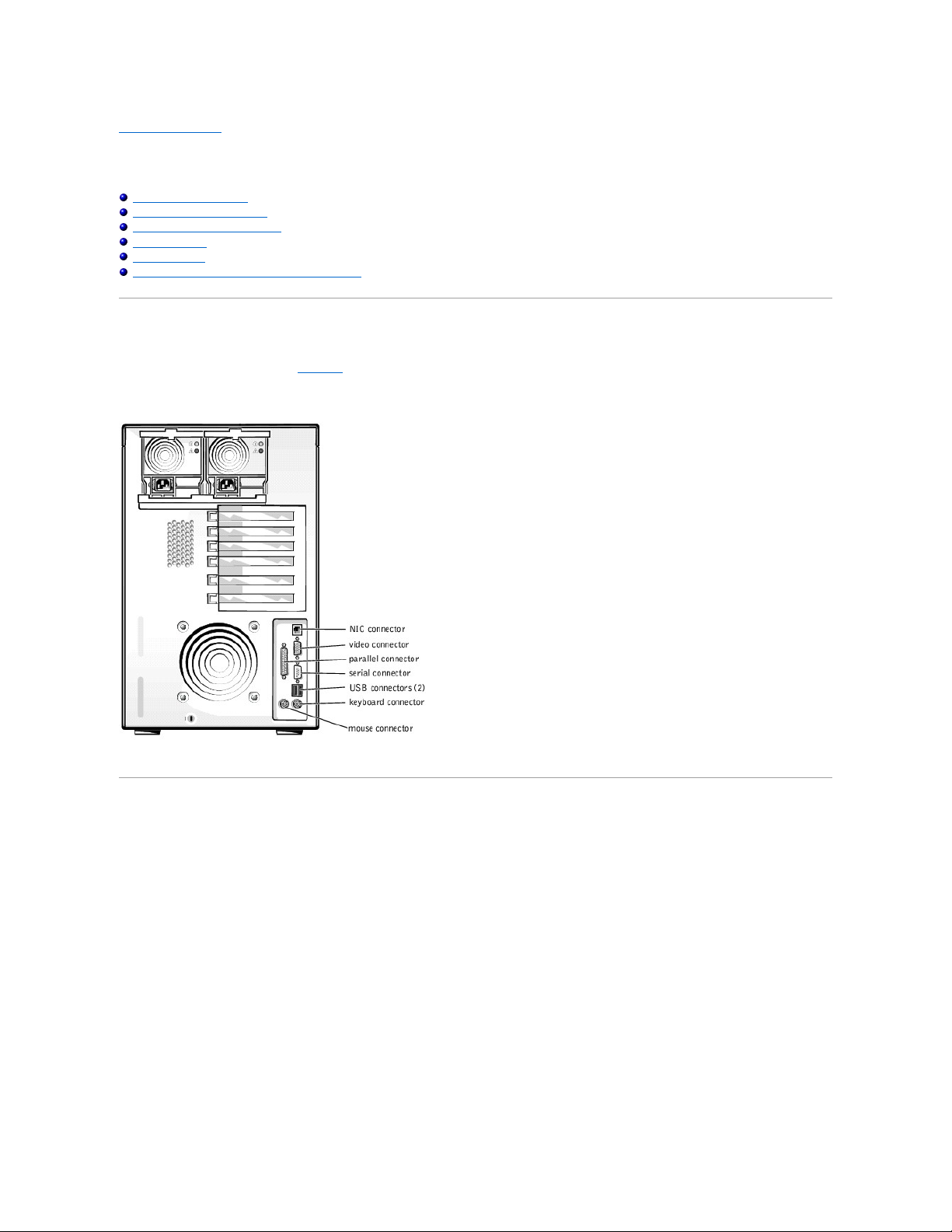
The I/O ports and connectors on the back panel of the system are the gateways through which the system communicates with external devices, such as a
keyboard, mouse, printer, and monitor. FigureB-1 identifies the I/O ports and connectors for your system.
Figure B-1. I/O Ports and Connectors
Serial and Parallel Connectors
The integrated serial connector uses a 9-pin D-subminiature connector on the back panel. This connector supports devices such as external modems, printers,
plotters, and mice that require serial data transmission (the transmission of data one bit at a time over one line).
Most software uses the term COM (for communications) plus a number to designate a serial connector (for example, COM1 or COM2). The default designation
of your system's integrated serial connector is COM1.
The integrated parallel connector uses a 25-pin D-subminiature connector on the system's back panel. This I/O port sends data in parallel format (where eight
data bits, or one byte, are sent simultaneously over eight separate lines in a single cable). The parallel connector is used primarily for printers.
Most software uses the term LPT (for line printer) plus a number to designate a parallel connector (for example, LPT1). The default designation of the system's
integrated parallel connector is LPT1.
Port designations are used, for example, in software installation procedures that include a step in which you identify the connector to which a printer is
attached, thus telling the software where to send its output. (An incorrect designation prevents the printer from printing or causes scrambled print.)
Expansion Cards Having a Serial or Parallel Connector
The system has an autoconfiguration capability for the serial connectors. This feature lets you add an expansion card containing a serial connector that has
the same designation as one of the integrated connectors, without having to reconfigure the card. When the system detects the duplicate serial connector on
the expansion card, it remaps (reassigns) the integrated connector to the next available designation.
Both the new and the remapped COM connectors share the same interrupt request (IRQ) setting, as follows:
l COM1, COM3: IRQ4 (shared setting)
l COM2, COM4: IRQ3 (shared setting)
These COM ports have the following I/O address settings:
l COM1: 3F8h
l COM2: 2F8h
l COM3: 3E8h
l COM4: 2E8h
For example, if you add an internal modem card with a port configured as COM1, the system then sees logical COM1 as the address on the modem card. It
automatically remaps the integrated serial connector that was designated as COM1 to COM3, which shares the COM1 IRQ setting. (Note that when you have
two COM ports sharing an IRQ setting, you can use either port as necessary but you may not be able to use them both at the same time.) If you install one or
more expansion cards with serial connectors designated as COM1 and COM3, the corresponding integrated serial connector is disabled.
Before adding a card that remaps the COM ports, check the documentation that accompanied your software to make sure that the software can be mapped to
the new COM port designation.
To avoid autoconfiguration, you may be able to reset jumpers on the expansion card so that the card's port designation changes to the next available COM
number, leaving the designation for the integrated connector as is. Alternatively, you can disable the integrated connectors through the System Setup
program. The documentation for your expansion card should provide the card's default I/O address and allowable IRQ settings. It should also provide
instructions for readdressing the connector and changing the IRQ setting, if necessary.
If you add an expansion card containing, for example a parallel connector configured as LPT1 (IRQ7, I/O address 378h), you must go into the System Setup
program to remap the integrated parallel connector.
For general information on how your operating system handles serial and parallel ports, and for more detailed command procedures, see your operating
system documentation.
Serial Connector
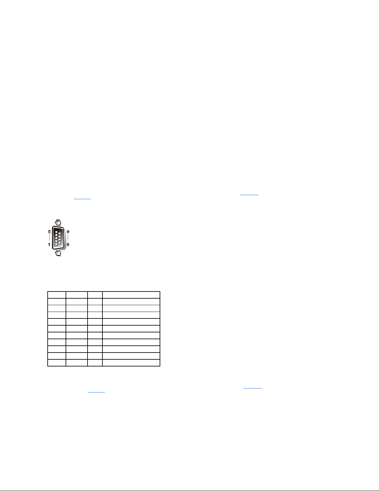
If you reconfigure your hardware, you may need pin number and signal information for the serial connector. FigureB-2 illustrates the pin numbers for the serial
connector and TableB-1 defines the pin assignments and interface signals for the serial connector.
Figure B-2. Serial Connector Pin Numbers
Parallel Connector
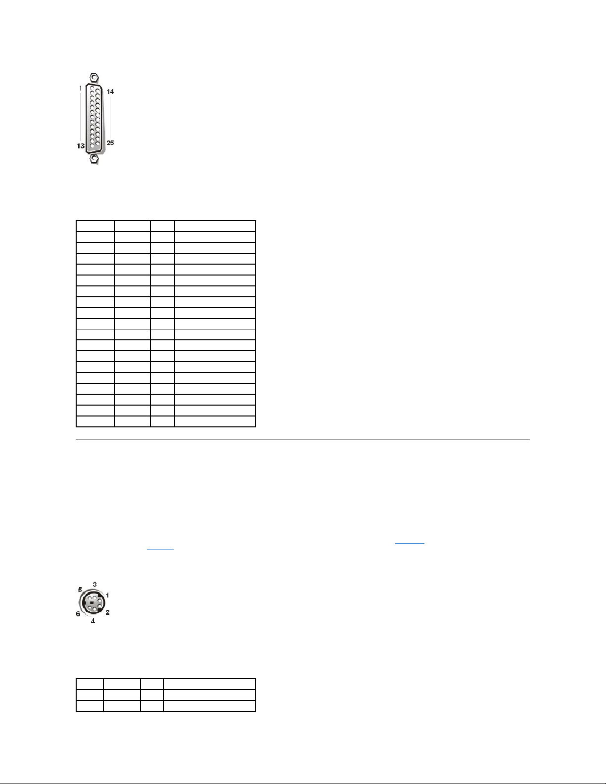
If you reconfigure your hardware, you may need pin number and signal information for the parallel connector. FigureB-3 illustrates the pin numbers for the
parallel connector and TableB-2 defines the pin assignments and interface signals for the parallel connector.
Figure B-3. Parallel Connector Pin Numbers
Table B-1. Serial Connector Pin Assignments
Pin
Signal
I/O
Definition
1
DCD I Data carrier detect
2
SIN I Serial input
3
SOUT O Serial output
4
DTR O Data terminal ready
5
GND
N/A
Signal ground
6
DSR I Data set ready
7
RTS O Request to send
8
CTS I Clear to send
9
RI I Ring indicator
Shell
N/A
N/A
Chassis ground
Keyboard and Mouse Connectors
The system uses a Personal System/2 (PS/2)-style keyboard and supports a PS/2-compatible mouse. Cables from both devices attach to 6-pin, miniature
Deutsche Industrie Norm (DIN) connectors on the back panel of your system.
Mouse driver software can give the mouse priority with the microprocessor by issuing IRQ12 whenever a new mouse movement is detected. The driver
software also passes along the mouse data to the application program that is in control.
Keyboard Connector
If you reconfigure your hardware, you may need pin number and signal information for the keyboard connector. FigureB-4 illustrates the pin numbers for the
keyboard connector and TableB-3 defines the pin assignments and interface signals for the keyboard connector.
Figure B-4. Keyboard Connector Pin Numbers
Table B-2. Parallel Connector Pin Assignments
Pin
Signal
I/O
Definition
1
STB#
I/O
Strobe
2
PD0
I/O
Printer data bit 0
3
PD1
I/O
Printer data bit 1
4
PD2
I/O
Printer data bit 2
5
PD3
I/O
Printer data bit 3
6
PD4
I/O
Printer data bit 4
7
PD5
I/O
Printer data bit 5
8
PD6
I/O
Printer data bit 6
9
PD7
I/O
Printer data bit 7
10
ACK# I Acknowledge
11
BUSY I Busy
12
PE I Paper end
13
SLCT I Select
14
AFD# O Automatic feed
15
ERR# I Error
16
INIT# O Initialize printer
17
SLIN# O Select in
18–25
GND
N/A
Signal ground
Table B-3. Keyboard Connector Pin Assignments
Pin
Signal
I/O
Definition
1
KBDATA
I/O
Keyboard data
2
NC
N/A
No connection
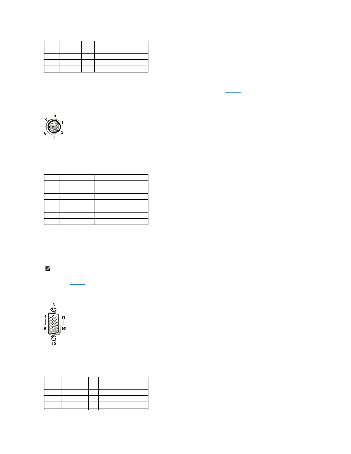
Mouse Connector
If you reconfigure your hardware, you may need pin number and signal information for the mouse connector. FigureB-5 illustrates the pin numbers for the
mouse connector, and TableB-4 defines the pin assignments and interface signals for the mouse connector.
Figure B-5. Mouse Connector Pin Numbers
Video Connector
The system uses a 15-pin high-density D-subminiature connector on the back panel for attaching a video graphics array (VGA)-compatible monitor to your
system. The video circuitry on the system board synchronizes the signals that drive the red, green, and blue electron guns in the monitor.
If you reconfigure your hardware, you may need pin number and signal information for the video connector. FigureB-6 illustrates the pin numbers for the video
connector, and TableB-5 defines the pin assignments and interface signals for the video connector.
Figure B-6. Video Connector Pin Numbers
3
GND
N/A
Signal ground
4
FVcc
N/A
Fused supply voltage
5
KBCLK
I/O
Keyboard clock
6
NC
N/A
No connection
Shell
N/A
N/A
Chassis ground
Table B-4. Mouse Connector Pin Assignments
Pin
Signal
I/O
Definition
1
MFDATA
I/O
Mouse data
2
NC
N/A
No connection
3
GND
N/A
Signal ground
4
FVcc
N/A
Fused supply voltage
5
MFCLK
I/O
Mouse clock
6
NC
N/A
No connection
Shell
N/A
N/A
Chassis ground
NOTE: Installing a video card automatically disables the system's integrated video subsystem.
Table B-5. Video Connector Pin Assignments
Pin
Signal
I/O
Definition
1
RED O Red video
2
GREEN
O
Green video
3
BLUE O Blue video
4
NC
N/A
No connection
USB Connectors
Your system contains two USB connectors for attaching USB-compliant devices. USB devices are typically peripherals such as mice, printers, keyboards, and
system speakers.
If you reconfigure your hardware, you may need pin number and signal information for the USB connectors. FigureB-7 illustrates the USB connector and
TableB-6 defines the pin assignments and interface signals for the USB connector.
Figure B-7. USB Connector Pin Numbers
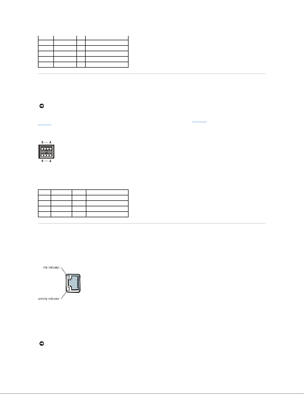
Integrated Network Interface Controller Connector
Your system has an integrated 10/100/1000-megabit-per-second (Mbps) network interface controller (NIC). The NIC provides all the functions of a separate
network expansion card while providing fast communication between servers and workstations and efficient utilization of host resources, freeing more of the
system resources for other applications. It supports 10 Base-T, 100 Base-TX, and 1000 Base-T Ethernet standards.
Figure B-8. NIC Connector
Network Cable Requirements
Your system's RJ45 NIC connector is designed for attaching an unshielded twisted pair (UTP) Ethernet cable equipped with a standard RJ45-compatible plug.
Press one end of the UTP cable into the NIC connector until the plug snaps securely into place. Connect the other end of the cable to an RJ45 jack wall plate or
to an RJ45 port on a UTP concentrator or hub, depending on your network configuration. Observe the following cabling restrictions for 10 Base-T, 100 Base-TX,
and 1000 Base-T networks.
l Use Category 5 or greater wiring and connectors.
5–8, 10
GND
N/A
Signal ground
9
VCC
N/A
Vcc
11
NC
N/A
No connection
12
DDC data out
O
Monitor detect data
13
HSYNC
O
Horizontal synchronization
14
VSYNC
O
Vertical synchronization
NOTICE: Do not attach a USB device or a combination of USB devices that draw a maximum current over 500 milliamperes (mA) per channel or +5 volts
(V). Attaching devices that exceed this threshold may cause the USB ports to shut down. See the documentation that accompanied the USB devices for
their maximum current ratings.
Table B-6. USB Connector Pin Assignments
Pin
Signal
I/O
Definition
1
Vcc
N/A
Supply voltage
2
DATA I Data in
3
+DATA
O
Data out
4
GND
N/A
Signal ground
NOTICE: To avoid line interference, voice and data lines must be in separate sheaths.

l The maximum cable run length (from a workstation to a hub) is 328 ft (100 m).
l Guidelines for operation of a network can be found in "Systems Considerations of Multi-Segment Networks" in the IEEE 802.3 standard.
Back to Contents Page

Back to Contents Page
Installing and Configuring SCSI Drivers
Dell™PowerEdge™1500SCSystemsUser'sGuide
The SCSISelect Utility
Troubleshooting for Windows NT
Troubleshooting for NetWare
This section describes how to install and configure the Dell SCSI device drivers included with your system. These device drivers are designed to work with the
Adaptec AIC-7899 Ultra 160/m SCSI-3 controller on the system board. Each channel of the AIC-7899 supports up to eight internal SCSI hard drives via SCSI
backplane boards.
If you are using an optional RAID Controller, see your RAID controller documentation for information on installing your SCSI device drivers.
For instructions on installing SCSI hardware devices such as hard drives, tape drives, or CD drives, see "Installing a Drive in the Peripheral Bay" in the
Installation and Troubleshooting Guide. After the SCSI devices are installed, install and configure any SCSI device drivers to enable them to communicate with
your operating system.
See "Using the Dell OpenManage Server Assistant CD" for instructions on creating a diskette of drivers for your operating system. For instructions on
configuring the SCSI device drivers, see the documentation that came with your operating system. You may also need to use the SCSISelect utility, discussed
in this section.
The SCSISelect Utility
The BIOS for the integrated Adaptec AIC-7899 SCSI controller includes the menu-driven SCSISelect configuration utility, which allows you to change SCSI
controller settings without opening the system. SCSISelect also contains SCSI disk utilities that let you low-level format or verify the disk media of your SCSI
hard drives.
Starting the SCSISelect Utility
You can start the SCSISelect utility by pressing <Ctrl><a> when the following prompt appears briefly during start-up:
Press<CTRL><A>forSCSISelect™Utility!
The first menu displays the Configure/View Host Adapter Settings and SCSI Disk Utilities options.
Using SCSISelect Menus
SCSISelect uses menus to list options that you can select. To select an option, press the up- and down-arrow keys to move the cursor to the option; then
press <Enter>.
In some cases, selecting an option displays another menu. You can return to the previous menu at any time by pressing <Esc>. To restore the original
SCSISelect default values, press <F6>.
SCSISelect Default Settings
Default settings for the integrated AIC-7899 SCSI controller are shown in TableC-1. These default settings are appropriate for most PCI systems. Run
SCSISelect only if you need to change any of the default settings.
For situations in which you might want or need to change the settings, see the description of each setting in the following subsections. To change any of the
default settings or to format or verify a disk, see "Using the SCSI Disk Utilities."
NOTE: To change the configuration settings, you must run the SCSISelect utility.
NOTE: Ifthehostadapterdoesnotcontrolthebootableharddrive,youmaywanttodisableitsBIOS.
Table C-1. AIC-7899 SCSI Controller Settings
Setting
Default
SCSI Bus Interface Definitions:
Host Adapter SCSI ID
7
SCSI Parity Checking
Enabled
Host Adapter SCSI Termination
Enabled or Automatic
Boot Device Options:
Boot Channel
A First
Boot SCSI ID
0
Boot LUN Number
0
SCSI Device/Configuration:
Sync Transfer Rate MB/Sec
160
Initiate Wide Negotiation
Yes (Enabled)

SCSI Bus Interface Definitions
The basic host adapter settings are the SCSISelect settings most likely to require modification:
l Host Adapter SCSI ID — Sets the host adapter's SCSI ID. The default setting is SCSI ID 7, which allows the host adapter to support narrow SCSI
devices in addition to wide SCSI devices. Dell recommends that you leave the host adapter set to SCSI ID 7.
l SCSI Parity Checking — Determines whether the host adapter verifies the accuracy of data transfer on the SCSI bus. The default setting is Enabled.
You should disable SCSI Parity Checking if any SCSI device connected to the host adapter does not support SCSI parity; otherwise, leave it enabled.
Most SCSI devices support SCSI parity. If you are unsure whether a device supports SCSI parity, consult the documentation for the device.
l Host Adapter SCSI Termination — Sets termination on the host adapter. The default setting for the AIC-7899 host adapter is Enabled or Automatic.
Dell recommends that you leave this option set to the default.
Boot Device Options
The boot device options allow you to specify the device from which to boot your system:
l Boot SCSI ID — Specifies the boot channel (A or B) for the dual-channel Adaptec 7899 host adapter. The default is A First.
l Boot LUN Number — Allows you to specify a particular logical unit number (LUN) from which to boot your boot device if your boot device has multiple
LUNs and BIOS Multiple LUN Support is enabled (see "SCSI Device/Configuration Settings"). The default setting is LUN 0.
SCSI Device/Configuration Settings
The SCSI device/configuration settings allow you to configure certain parameters for each device on the SCSI bus. To configure a specific device, you must
know the SCSI ID assigned to that device. If you are not sure of the SCSI ID, see "Using the SCSI Disk Utilities."
l Sync Transfer Rate MB/sec — Sets the maximum synchronous data transfer rate that the host adapter supports.
The AIC-7899 host adapter supports rates up to 160 megabytes per second (MB/sec). The default for the AIC-7899 host adapter is 160 MB/sec.
If the host adapter is set to not negotiate for synchronous data transfer, the maximum synchronous transfer rate is the maximum rate that the host
adapter accepts from the device during negotiation. (This setting is standard SCSI protocol.)
l Initiate Wide Negotiation — Determines whether the host adapter attempts 16-bit data transfer instead of 8-bit data transfer. The default is Yes.
When this option is set to Yes, the host adapter attempts 16-bit data transfer. When this option is set to No, 8-bit data transfer is used unless the SCSI
device itself requests wide negotiation. The effective transfer rate is doubled when 16-bit data transfer is used because the data path for wide SCSI is
twice the size of normal 8-bit SCSI.
l Enable Disconnection (sometimes called disconnect/reconnect) — Determines whether the host adapter allows the SCSI device to disconnect from the
SCSI bus. Enabling disconnection allows the host adapter to perform other operations on the SCSI bus while the SCSI device is temporarily
disconnected. The default setting is Yes.
Leave Enable Disconnection set to Yes if two or more SCSI devices are connected to the host adapter. This optimizes SCSI bus performance. If only
one SCSI device is connected to the host adapter, set Enable Disconnection to No to achieve slightly better performance.
l Send Start Unit Command — Determines whether the start unit command is sent to the SCSI device during the boot routine. The default is Yes.
Setting this option to Yes reduces the load on your system's power supply by allowing the host adapter to start SCSI devices one at a time when you
boot your system. When this option is set to No, the devices are allowed to start at the same time. Most devices require you to set a jumper before they
can respond to this command.
Enable Disconnection
Yes (Enabled)
Send Start Unit Command
Yes (Enabled)
Enable Write Back Cache
Yes or N/C
BIOS Multiple LUN Support
No (Enabled)
Include in BIOS Scan
Yes(Enabled)
Advanced Configuration:
Reset SCSI Bus at IC Initialization
Enabled
Display <Ctrl><a> Message During BIOS Initialization
Enabled
Extended BIOS Translation For DOS Drivers > 1 GB
Enabled
Silent/Verbose Mode
Verbose
Host Adapter BIOS
Enabled
Domain Validation
Enabled
Support Removable Disks Under BIOS As Fixed Disks
Boot Only
BIOS Support For Bootable CD
Enabled
BIOS Support For Int 13 Extensions
Enabled
Support For Ultra SCSI Speed
Enabled
NOTE: For the full name of an abbreviation or acronym used in this table, see the Glossary.
NOTE: Some 8-bit SCSI devices may have trouble handling wide negotiation, which may result in erratic behavior or a hang condition. For these
devices, set Initiate Wide Negotiation to No.
NOTE: For many devices, if Send Start Unit Command is set to Yes, the boot routine time will vary depending on how long it takes each drive to
start.

l Enable Write Back Cache — Signals the completion of a write request as soon as the data is in cache. Actual writing to the disk occurs at a later time.
The default setting is N/C or Yes.
l BIOS Multiple LUN Support — Provides support for peripherals that contain multiple SCSI devices, such as autoloading tape drives and CD changers.
l Include in BIOS Scan — Enables you to set whether the system BIOS scans this device during system start-up. The default is Yes.
Advanced Configuration Settings
The advanced host adapter settings should not be changed unless absolutely necessary. These values are set by Dell, and changing them may cause conflicts
with the SCSI devices.
l Reset SCSI Bus at IC Initialization — Enables the SCSI bus to be reset when the controller is initialized. The default is Enabled.
l Display <Ctrl><a> Message During BIOS Initialization — Determines whether the Press<CTRL><A>forSCSISelect™Utility! message appears on
your screen during system start-up. The default setting is Enabled. If this setting is disabled, you can still run the SCSISelect utility by pressing
<Ctrl><a> after the host adapter BIOS banner appears.
l Extended BIOS Translation For DOS Drives > 1 GB — Determines whether extended translation is available for SCSI hard drives with capacities
greaterthan1GB.ThedefaultsettingisEnabled.
The standard translation scheme for SCSI host adapters provides a maximum accessible capacity of 1 GB. To support hard drives larger than 1 GB, the
78xx series host adapters include an extended translation scheme that supports hard drives as large as 8 GB, with a maximum partition size of 2 GB
under the DOS operating system.
It is not necessary to enable the Extended BIOS Translation setting if you are using another operating system.
When you partition a hard drive larger than 1 GB, use the MS-DOS®fdisk utility as you normally would. Because the cylinder size increases to 8 MB
under extended translation, the partition size you choose must be a multiple of 8 MB. If you request a size that is not a multiple of 8 MB, fdisk rounds up
tothenearestwholemultipleof8MB.
l Silent/Verbose Mode — Displays the host adapter information during system start-up. The default is Verbose.
l Host Adapter BIOS — Enables or disables the host adapter BIOS. The default setting is Enabled.
If you are booting from a SCSI hard drive connected to the host adapter, the BIOS must be enabled. You should disable the host adapter BIOS if the
peripherals on the SCSI bus (for example, CD drives) are all controlled by device drivers and do not need the BIOS.
l Domain Validation — Instructs the host adapter not to accept a negotiated speed until a validation test is successfully performed. After determining the
speed that a target device is capable of, the host adapter sends a Write Buffer command to the target device. The data transfer occurs at the full
speedinitially.Theinitiatorreadsandteststhedataandidentifiesanyparityorcyclicredundancycheck(CRC)errors.Ifthetestfails,theinitiator
lowers its speed and repeats the test. In this manner, a compatible speed will be found and locked in before user data transfers begin. The default is
Enabled.
l Support Removable Disks Under BIOS As Fixed Disks — Controls which removable-media drives are supported by the host adapter BIOS. The default
setting is Boot Only. The following choices are available.
¡ Boot Only — Only the removable-media drive designated as the boot device is treated as a hard drive.
¡ All Disks — All removable-media drives supported by the BIOS are treated as hard drives.
¡ Disabled — No removable-media drives are treated as hard drives. In this situation, software drivers are needed because the drives are not
controlled by the BIOS.
l BIOS Support For Bootable CD-ROM — Determines whether the host adapter BIOS provides support for booting from a CD drive. The default setting is
Enabled.
l BIOS Support For Int 13 Extensions — Determines whether the host adapter BIOS supports disks with more than 1024 cylinders. The default setting is
Enabled.
l Support For Ultra SCSI Speed — Determines whether the host adapter supports the fast transfer rates (20–40 MB/sec). The default setting is Enabled.
Using the SCSI Disk Utilities
To access the SCSI disk utilities, select SCSI Disk Utilities from the menu that appears when you start SCSISelect. When the option is selected, SCSISelect
immediately scans the SCSI bus (to determine the devices installed) and displays a list of all SCSI IDs and the device assigned to each ID.
When you select a specific ID and device, a menu appears, displaying the Format Disk and Verify Disk Media options.
l Format Disk — Runs a utility that allows you to perform a low-level format on a hard drive. Most SCSI disk drives are formatted at the factory and do
not need to be formatted again. The Adaptec Format Disk utility is compatible with the majority of SCSI disk drives.
l Verify Disk Media — Runs a utility that allows you to scan the media of a hard drive for defects. If the utility finds bad blocks on the media, it prompts
you to reassign them; if you select Yes, those blocks are no longer used. You can press <Esc> at any time to exit the utility.
NOTE: The setting for BIOS Multiple LUN Support must be No or Enabled (default) if a tape autoloader is connected.
NOTICE: Back up your hard drive before you change the translation scheme. All data is erased when you change from one translation scheme to
another.
NOTE: Several SCSISelect options are not valid unless the host adapter BIOS is enabled.
NOTICE: If a removable-media SCSI device is controlled by the host adapter BIOS, do not remove the media while the drive is on or you might lose
data. If you want to be able to remove media while the drive is on, install your removable-media device driver and set this option to Disabled.
NOTICE: The Format Disk option destroys all data on the hard drive.

Exiting SCSISelect
To exit SCSISelect, press <Esc> until a message prompts you to exit. (If you changed any 78xx series host adapter settings, you are prompted to save the
changes before you exit.) At the prompt, select Yes to exit, and then press any key to reboot the system. Any changes that you made in SCSISelect take effect
after the system boots. (You can select No at the prompt if you are not ready to exit SCSISelect.)
Troubleshooting for Windows NT
The boot manager for Windows NT®contains recovery logic to allow you to return to the last known good configuration. If you have changed your host
adapter configuration and Windows NT no longer boots, perform the following steps to recover it:
1. Undo any hardware changes that you have made to the system since it was last operational.
2. Reboot the system. Watch the display carefully during start-up. If the following message appears, press the spacebar, type l at the next screen, and
then follow the instructions on the screen to continue booting with the last known good configuration:
Press spacebar NOW to invoke the Last Known Good menu
3. When your system is operational again, check all of the hardware and software configuration changes that you want to make. Look specifically for
conflicts with parts of the existing system configuration that are not being changed.
If you cannot determine the source of the error, see, "Getting Help" in the Installation and Troubleshooting Guide for instructions on contacting Dell for
technical assistance.
Troubleshooting for NetWare
Any error that occurs while the driver is initializing prevents it from loading. If an error does occur, the driver causes the system to beep and then display the
following numbered error message:
xxx message
The xxx indicates the error code and message is a line of text describing the error. The error codes are divided into three categories:
l 000-099 — Non-host-adapter specific
l 100-299 — Host-adapter specific
l 300-999 — Reserved
Specific error codes, such as those in the following subsections, appear only if you have installed the host adapters and drivers that generate them.
Non-Host-Adapter Specific Error Codes
The following error codes alert you to error conditions caused by factors not related to the host adapter:
000 Failed ParseDriverParameters call
A call to the NetWare®ParseDriverParameters routine has failed for some unknown reason. The command line contains errors, or you pressed <Esc> at the
port or slot prompt.
001 Unable to reserve hardware, possible conflict
The driver failed in its attempt to reserve the host adapter's hardware settings (that is, direct memory access [DMA] and interrupt request [IRQ] settings).
Another card in your system may be causing a conflict with the host adapter.
002 NetWare rejected card Failed AddDiskSystem call
The driver failed in its attempt to register the host adapter with NetWare. The file server may not have enough memory.
003 Invalid command line option entered > option
An invalid option was entered on the command line. The invalid option that was entered is also displayed.
004 Invalid command line, please enter correctly
The driver was unable to understand the command line options that you entered. Be sure that you have entered these options correctly.
Host-Adapter Specific Error Codes
The following error codes alert you to error conditions caused by factors related to the host adapter:
200 No host adapter found for this driver to register
No Adaptec 78xx host adapter was found in your system for the driver to register. Be sure that the host adapter is properly configured and properly seated in
the slot.
203 Invalid 'device' setting
 Loading...