

Page 1
53-1001995-01
August 31, 2010
PowerConnect™ B-MLXe
Series
Getting Started Guide
入门指南
使用說明指南
Guide de mise en route
Handbuch zum Einstieg
Panduan Pengaktifan
Guida introduttiva
はじめに
시작 안내서
Guia de Noções Básicas
Guía de introducción
53-1001995-01
*53-1001995-01*
Page 2

Page 3

53-1001995-01
August 31, 2010
PowerConnect™ B-MLXe
Series
Getting Started Guide
53-1001995-01
*53-1001995-01*
Page 4
Notes, Cautions, and Warnings
NOTE
CAUTION
DANGER
A NOTE indicates important information that helps you make better use of your computer.
A CAUTION indicates potential damage to hardware or loss of data if instructions are not followed.
A DANGER indicates a potential for property damage, personal injury, or death.
____________________
Information in this document is subject to change without notice.
© 2010 Dell Inc. All rights reserved.
Reproduction of these materials in any manner whatsoever without the written permission of Dell Inc. is strictly forbidden.
Trademarks used in this text: Dell, the DELL logo, Inspiron, Dell Precision, Dimension, OptiPlex, Latitude, PowerEdge, PowerVault, PowerApp,
PowerConnect, and Dell OpenManage are trademarks of Dell Inc.; Intel, Pentium, and Celeron are registered trademarks of Intel Corporation in
the U.S. and other countries; Microsoft, Windows, Windows Server, MS-DOS and Windows Vista are either trademarks or registered trademarks of
Microsoft Corporation in the United States and/or other countries.
Other trademarks and trade names may be used in this document to refer to either the entities claiming the marks and names or their products.
Dell Inc. disclaims any proprietary interest in trademarks and trade names other than its own.
Regulatory Model Codes: MLXe-4, MLXe-8, MLXe-16
2 PowerConnect B-MLXe Getting Started Guide
53-1001995-01
Page 5

In this guide
•
Introduction. . . . . . . . . . . . . . . . . . . . . . . . . . . . . . . . . . . . . . . . . . . . . . . . . . . . 3
•
Items required for installation. . . . . . . . . . . . . . . . . . . . . . . . . . . . . . . . . . . . . 7
•
Site planning and safety guidelines . . . . . . . . . . . . . . . . . . . . . . . . . . . . . . . . 8
•
Unpacking the PowerConnect B-MLXe Series . . . . . . . . . . . . . . . . . . . . . . . 11
•
Lifting guidelines for the 8-slot and 16-slot chassis . . . . . . . . . . . . . . . . . . 12
•
Mounting a chassis in a rack. . . . . . . . . . . . . . . . . . . . . . . . . . . . . . . . . . . . . 13
•
Installing modules . . . . . . . . . . . . . . . . . . . . . . . . . . . . . . . . . . . . . . . . . . . . . 14
•
Installing power supplies . . . . . . . . . . . . . . . . . . . . . . . . . . . . . . . . . . . . . . . . 18
•
Connecting AC power . . . . . . . . . . . . . . . . . . . . . . . . . . . . . . . . . . . . . . . . . . . 21
•
Connecting DC Power. . . . . . . . . . . . . . . . . . . . . . . . . . . . . . . . . . . . . . . . . . . 22
•
Managing cables . . . . . . . . . . . . . . . . . . . . . . . . . . . . . . . . . . . . . . . . . . . . . . 24
•
Attaching a management station . . . . . . . . . . . . . . . . . . . . . . . . . . . . . . . . . 24
•
Activating the power source. . . . . . . . . . . . . . . . . . . . . . . . . . . . . . . . . . . . . . 25
•
Verifying proper operation . . . . . . . . . . . . . . . . . . . . . . . . . . . . . . . . . . . . . . . 26
•
Assigning passwords . . . . . . . . . . . . . . . . . . . . . . . . . . . . . . . . . . . . . . . . . . . 27
•
Configuring IP addresses. . . . . . . . . . . . . . . . . . . . . . . . . . . . . . . . . . . . . . . . 28
•
Connecting the PowerConnect B-MLXe Series to a network device . . . . . . 30
Introduction
This guide provides instructions for unpacking, installing, and setting up a PowerConnect B-MLXe Series 4-slot,
8-slot, and 16-slot chassis as a standalone unit. Note the following additional documentation:
•
For detailed installation and configuration instructions, refer to the appropriate hardware installation guide for
this product.
•
For rack-specific installation instructions, refer to the appropriate rack mount installation procedures.
The PowerConnect B-MLXe Series 4-slot chassis (Figure 1 on page 4) and 8-slot chassis (Figure 2 on page 5) can be
installed in the following ways:
•
As standalone units on a flat surface.
•
In a 19-in. Electronic Industries Association cabinet (EIA310-D). The B-MLXe Series units have built-in mounting
brackets for installing in racks.
•
In a mid-mount telecommunications (Telco) rack. A mid-mount kit can be ordered separately from your
PowerConnect supplier to center mount the PowerConnect unit in the rack. It contains two L-shaped mounting
brackets and instructions for installing the brackets and mounting the unit.
The PowerConnect B-MLXe Series 16-slot chassis (Figure 3 on page 6) can be installed in the following ways:
•
In a 19-in. Electronic Industries Association cabinet (EIA310-D). The B-MLXe Series units have built-in mounting
brackets for installing in racks.
•
In a mid-mount telecommunications (Telco) rack. A mid-mount kit can be ordered separately from your
PowerConnect supplier to center mount the PowerConnect unit in the rack. It contains two L-shaped mounting
brackets and instructions for installing the brackets and mounting the unit.
PowerConnect B-MLXe Getting Started Guide 3
53-1001995-01
Page 6
The basic configuration steps required to set up the PowerConnect B-MLXe Series are listed in this guide. Additional
7
6
5
1324
8910
configuration information is provided in the hardware installation guide.
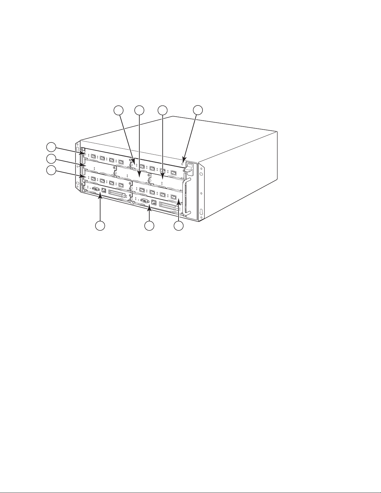
Figure 1 illustrates the PowerConnect B-MLXe Series 4-slot chassis and components location.
FIGURE 1
1 Interface slot 2 4 ESD connector 7 Interface slot 3 10 Interface slot 4
2 Switch fabric slot 2 5 Interface slot 1 8 Management slot 1
3 Switch fabric slot 3 6 Switch fabric slot 1 9 Management slot 2
PowerConnect B-MLXe 4-slot chassis
4 PowerConnect B-MLXe Getting Started Guide
53-1001995-01
Page 7
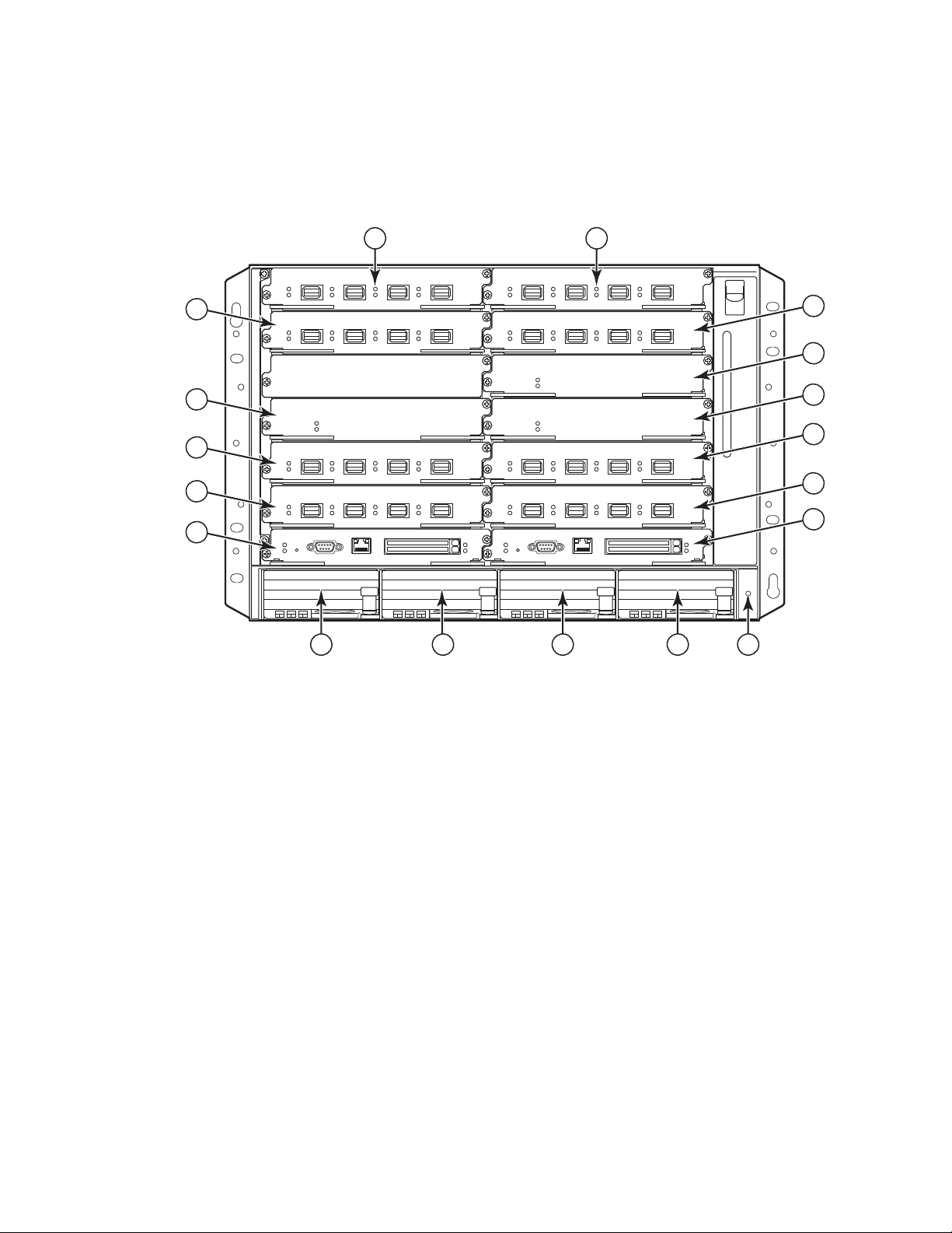
Figure 2 illustrates the PowerConnect B-MLXe Series 8-slot chassis and components location.
8
10
12
6
9
7
5
4
3
14 15
11
16 17
1 2
13
18
FIGURE 2
PowerConnect B-MLXe 8-slot chassis
1 Interface slot 1 6 Switch fabric slot 2 11 Interface slot 8 16 Power supply slot 3
2 interface slot 2 7 Switch fabric slot 3 12 Management slot 1 17 Power supply slot 4
3 Interface slot 3 8 Interface slot 5 13 Management slot 2 18 ESD connector
4 Interface slot 4 9 Interface slot 6 14 Power Supply slot 1
5 Switch Fabric slot 1 10 Interface slot 7 15 Power Supply slot 2
PowerConnect B-MLXe Getting Started Guide 5
53-1001995-01
Page 8

Figure 3 illustrates the PowerConnect B-MLXe Series 16-slot chassis and components location.and components
12
13
14
15
16
17
18
19
20
21
22
23
1
2
3
4
5
6
7
8
91011
location.
FIGURE 3
PowerConnect B-MLXe 16-slot chassis
1-16 Interface slots 1-16 20 Switch fabric slot 4
17 Switch fabric slot 1 21 Management slot 1
18 Switch fabric slot 2 22 Management slot 2
19 Switch fabric slot 3 23 ESD connector
6 PowerConnect B-MLXe Getting Started Guide
53-1001995-01
Page 9

Items required for installation
NOTE
This document describes how to set up the PowerConnect B-MLXe Series 4-slot, 8-slot, and 16-slot chassis and
mount them into 19-inch equipment racks using the brackets built onto each chassis. To center-mount the chassis
in a rack, order the mid-mount rack kit from your PowerConnect supplier. Installation instructions are provided with
the rack kit. This section describes items shipped with the PowerConnect B-MLXe Series and items you will need for
installation.
Items shipped with units
The following items are shipped:
•
The 4-slot chassis ships with the following components installed:
-
Two high-speed switch fabric modules.
-
A slot blank in each empty module slot. The slot blank covers a slot that does not currently have a module
installed in it, ensuring proper airflow.
-
A fan tray assembly, which is located in the front right side of the router. For more information about fans,
refer to your hardware installation guide.
-
One power supply (AC or DC).
•
The 8-slot chassis ships with the following components installed:
-
Two high-speed switch fabric modules.
-
A slot blank in each empty module slot. The slot blank covers a slot that does not currently have a module
installed in it, ensuring proper airflow.
-
A fan tray assembly, which is located in the front right side of the router. For more information about fans,
refer to your hardware installation guide.
-
Two power supplies (AC or DC).
•
The 16-slot chassis ships with the following components installed:
-
Three high-speed switch fabric modules.
-
A slot blank in each empty module slot. The slot blank covers a slot that does not currently have a module
installed in it, ensuring proper airflow.
-
A fan tray assembly, located in the front right side of the chassis, and two fan assemblies located at the rear
of the chassis. For more information about fans, refer to your hardware installation guide.
-
Four power supplies (AC or DC).
•
Warranty card.
•
A 115V AC power cable for each AC power supply that you purchase from Dell.
•
Web pointer card containing software images and user documentation (including this guide).
If any items are missing, contact the place of purchase.
Items that you must provide
•
Assembled 19-inch Electronic Industries Association cabinet (EIA310-D) equipment rack.
•
Standard #12-24 pan-head screws for mounting the chassis to equipment racks.
PowerConnect B-MLXe Getting Started Guide 7
53-1001995-01
Page 10
•
NOTE
DANGER
DANGER
#2 Phillips-head screwdriver.
•
A large flat-blade screwdriver.
•
Mid-mount rack kit (optional). Order from your PowerConnect supplier.
•
An ESD wrist strap with a plug for connection to the ESD connector on the chassis.
Site planning and safety guidelines
The following steps and safety precautions are required to ensure correct installation and operation.
Site planning
Follow these steps to ensure your site is ready for installation.
Cabling infrastructure
Ensure that the proper cabling is installed in the site. For information on cabling, see your hardware installation
guide.
Installation location
Before installing the chassis, plan its location and orientation relative to other devices and equipment. For cooling
purposes, allow a minimum of 15.24 cm (6 in.) of space between the sides, front, and the back of the chassis and
walls or other obstructions. If a chassis is installed within a perforated enclosure, the perforations must have
openings of at least 60 percent of the surface.
The PowerConnect B-MLXe series chassis is suitable for installation in a Network Telecommunication facility and
where NEC requirements apply. Additionally it may be installed in either a Common Bonding Network (CBN) or Isolated
Bonding Network (IBN). It is not intended for Outside Plant installations (OSP).
Safety guidelines
Before proceeding with installation, read the cautions and warnings that apply to the PowerConnect B-MLXe Series.
General precautions
The procedures in this manual are for qualified service personnel.
All fiber-optic interfaces use Class 1 Lasers.
8 PowerConnect B-MLXe Getting Started Guide
53-1001995-01
Page 11
CAUTION
Do not install the chassis in an environment where the operating ambient temperature might
CAUTION
CAUTION
CAUTION
CAUTION
DANGER
DANGER
DANGER
exceed 40οC (104οF).
Make sure the air flow around the front, sides, and back of the chassis is not restricted.
If you do not install a module in a slot, you must keep the slot blank in place. If you operate
the chassis with an uncovered slot, the system may overheat.
Never leave tools inside the chassis.
Power precautions
Use a separate branch circuit for each AC power cord for redundancy in case one of the
circuits fails.
Make sure to choose the appropriate circuit device, depending on the number of AC power
supplies installed in the chassis.
Disconnect the power cord from all power sources to completely remove power from the
chassis.
Make sure that the power source circuits are properly grounded, then use the power cord
supplied with the chassis to connect it to the power source.
PowerConnect B-MLXe Getting Started Guide 9
53-1001995-01
Page 12

DANGER
If the installation requires a different power cord than the one supplied with the chassis,
DANGER
DANGER
CAUTION
CAUTION
CAUTION
make sure you use a power cord displaying the mark of the safety agency that defines the
regulations for power cords in your country. The mark is your assurance that the power cord
can be used safely with the chassis.
Make sure the rack or cabinet housing the chassis is adequately secured to prevent it from
becoming unstable or falling over.
Mount the chassis in a rack or cabinet as low as possible. Place the heaviest chassis at the
bottom and progressively place lighter units above.
Ensure that the chassis does not overload the power circuits, wiring, and over-current
protection. To determine the possibility of overloading the supply circuits, add the ampere
(amp) ratings of all devices installed on the same circuit as the chassis. Compare this total
with the rating limit for the circuit. The maximum ampere ratings are usually printed on the
chassis near the input power connectors.
B-MLXe series products with DC power sources are intended for installation in restricted
access areas only. A restricted access area is where access can be gained only by service
personnel through the use of a special tool, lock and key, or other means of security, and is
controlled by the authority responsible for the location.
B-MLXe series products with AC power sources are intended for installation in restricted
access areas only. A restricted access area is a location where access can be gained only by
service personnel through the use of a special tool, lock and key, or other means of security.
10 PowerConnect B-MLXe Getting Started Guide
53-1001995-01
Page 13
CAUTION
For the DC input circuit to the system of a 16-slot chassis (1800W supply), make sure there
CAUTION
is a UL-Listed 60 amp circuit breaker, minimum -48VDC, double pole, on the input lugs to the
power supply. The input wiring for connection to the product should be copper wire, 6 AWG,
marked VW-1, and rated minimum 90οC.
For the NEBS-compliant installation of 16-slot chassis with AC and DC systems, use a ground
wire of at least 6 American Wire Gauge (AWG). The ground wire should have an
agency-approved crimped connector (provided with the device) attached to one end, with the
other end attached to building ground. The connector must be crimped with the proper tool,
allowing it to be connected to both ground screws on the enclosure. Before crimping the
ground wire into the provided ground lug, ensure the bare copper wire has been cleaned and
antioxidant is applied to the bare wire.
Unpacking the PowerConnect B-MLXe Series
The PowerConnect B-MLXe Series ships with several items. Review the items listed under “Items shipped with units”
on page 7, and verify the contents. If any items are missing, contact the place of purchase.
Remove your B-MLXe chassis from the shipping carton. Save the shipping carton and packing materials in case you
need to move or ship the chassis at a later time.
Installing a PowerConnect B-MLXe Series chassis in a rack
This section describes the following tasks:
•
“Preparing to mount a chassis in a rack”
•
“Removing shipping screws from the 4-slot and 8-slot chassis”
•
“Lifting guidelines for the 8-slot and 16-slot chassis”
•
“Mounting a chassis in a rack”
Preparing to mount a chassis in a rack
Because of the weight of a fully loaded PowerConnect B-MLXe Series chassis, Dell recommends mounting a chassis
in a rack before installing modules and AC power supplies if necessary.
In a standard 19-inch (EIA310-D) rack, you can install
•
Up to ten PowerConnect B-MLXe Series 4-slot chassis.
•
Up to six PowerConnect B-MLXe Series 8-slot chassis.
•
Up to three PowerConnect B-MLXe Series 16-slot chassis.
PowerConnect B-MLXe Getting Started Guide 11
53-1001995-01
Page 14
For each PowerConnect B-MLXe Series chassis that you install in a rack, you must provide four standard #12-24
NOTE
DANGER
3
1
2
pan-head screws with which to mount and secure the chassis. Before performing this task, you should have an
assembled rack and a #2 Phillips-head screwdriver.
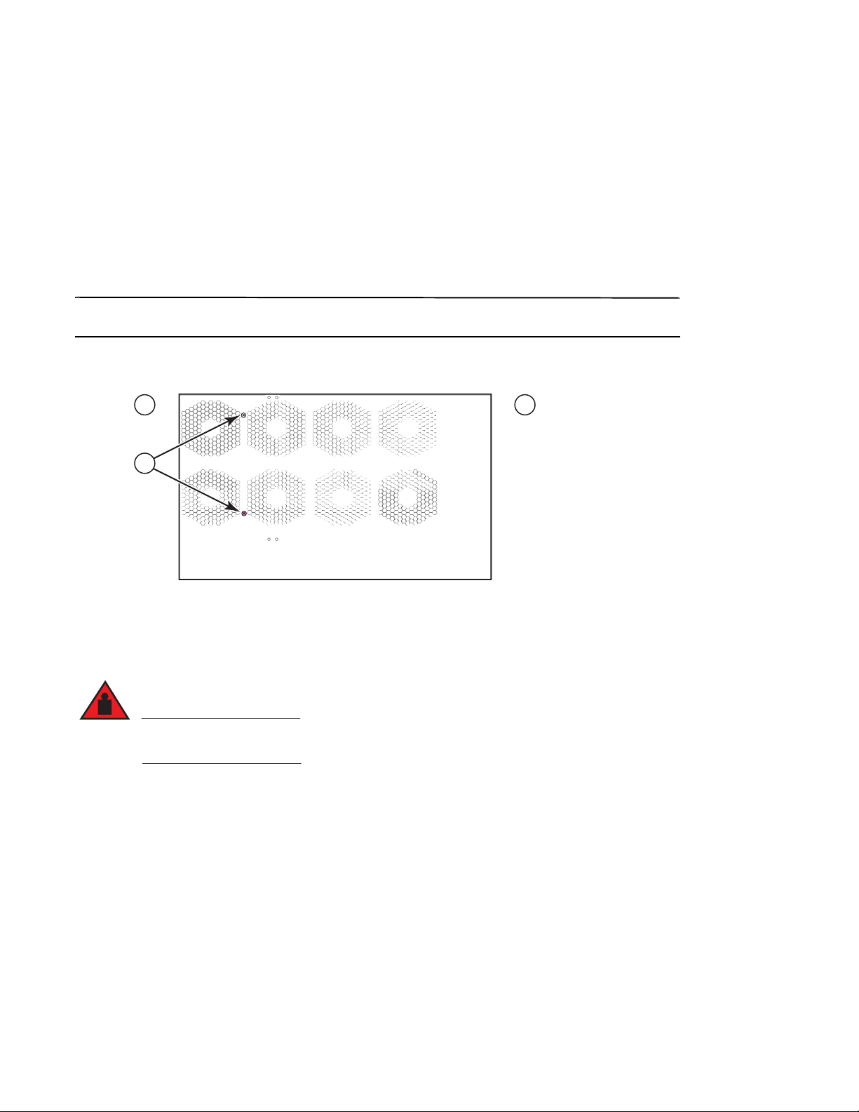
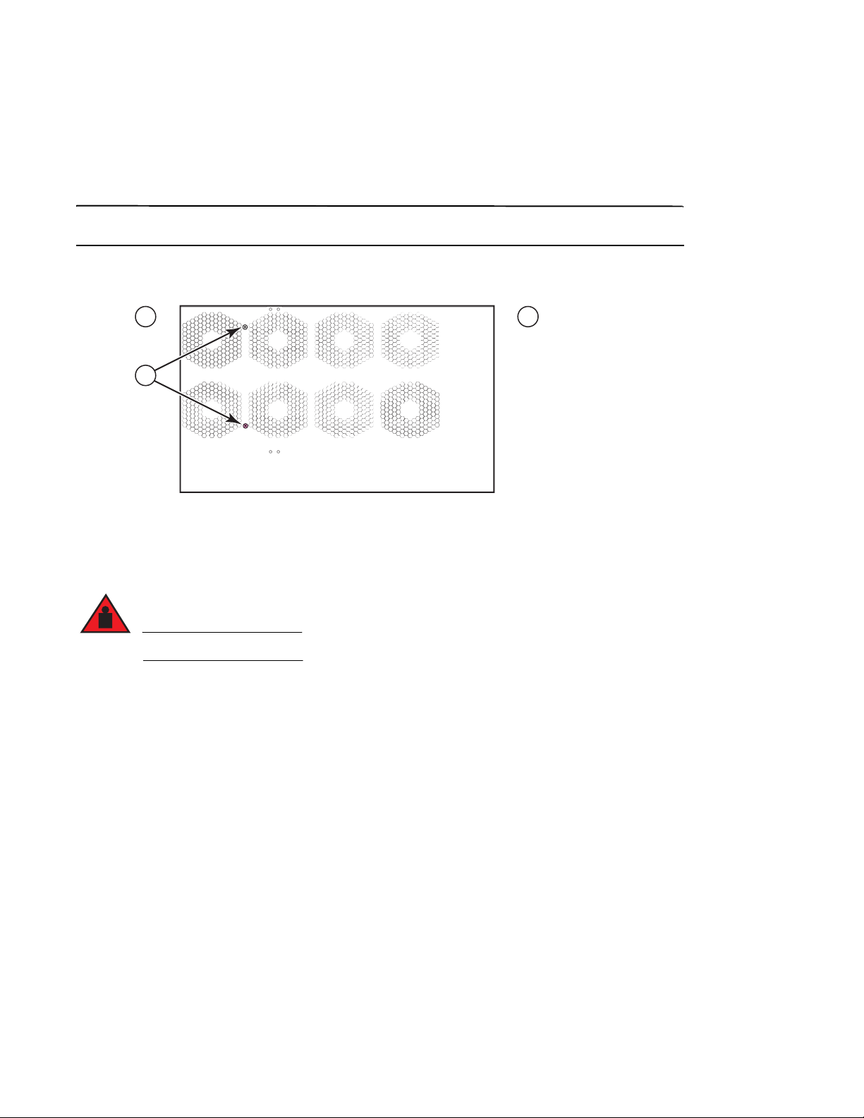
Removing shipping screws from the 4-slot and 8-slot chassis
The PowerConnect B-MLXe Series 4-slot and 8-slot units ship with two screws installed in the right side of the
chassis. These screws secure the fan tray and protect it from damage during shipment. You must remove these
screws before installing the router. Figure 4 on page 12 shows the location of these screws.
You will need a #2 Phillips screwdriver to remove these screws.
FIGURE 4
1 Front 2 Rear 3 Shipping screws
Removing the shipping screws from 4-slot and 8-slot chassis
Lifting guidelines for the 8-slot and 16-slot chassis
A fully-populated B-MLXe 16-slot chassis is heavy. TWO PEOPLE ARE REQUIRED WHEN LIFTING,
HANDLING, OR MOUNTING THESE DEVICES.
Follow these guidelines for lifting and moving the 8-slot or 16-slot chassis:
•
Before lifting or moving the chassis, disconnect all external cables.
•
Do not attempt to lift a fully configured chassis by yourself. Use two people to lift the chassis.
•
It is recommended that you remove chassis components before installing the chassis in a rack.
12 PowerConnect B-MLXe Getting Started Guide
53-1001995-01
Page 15
Mounting a chassis in a rack
NOTE
5"
3"
1 2
Follow these steps to mount a PowerConnect B-MLXe Series chassis in a rack.
You must provide standard #12-24 pan-head screws to mount each chassis in a rack. You will need a Phillips
screwdriver to perform this task.
1. Determine the position of each chassis in the rack. For example, place units with the fewest modules near the
top of the rack, units with more modules near the middle of the rack, and fully populated units near the bottom
of the rack.
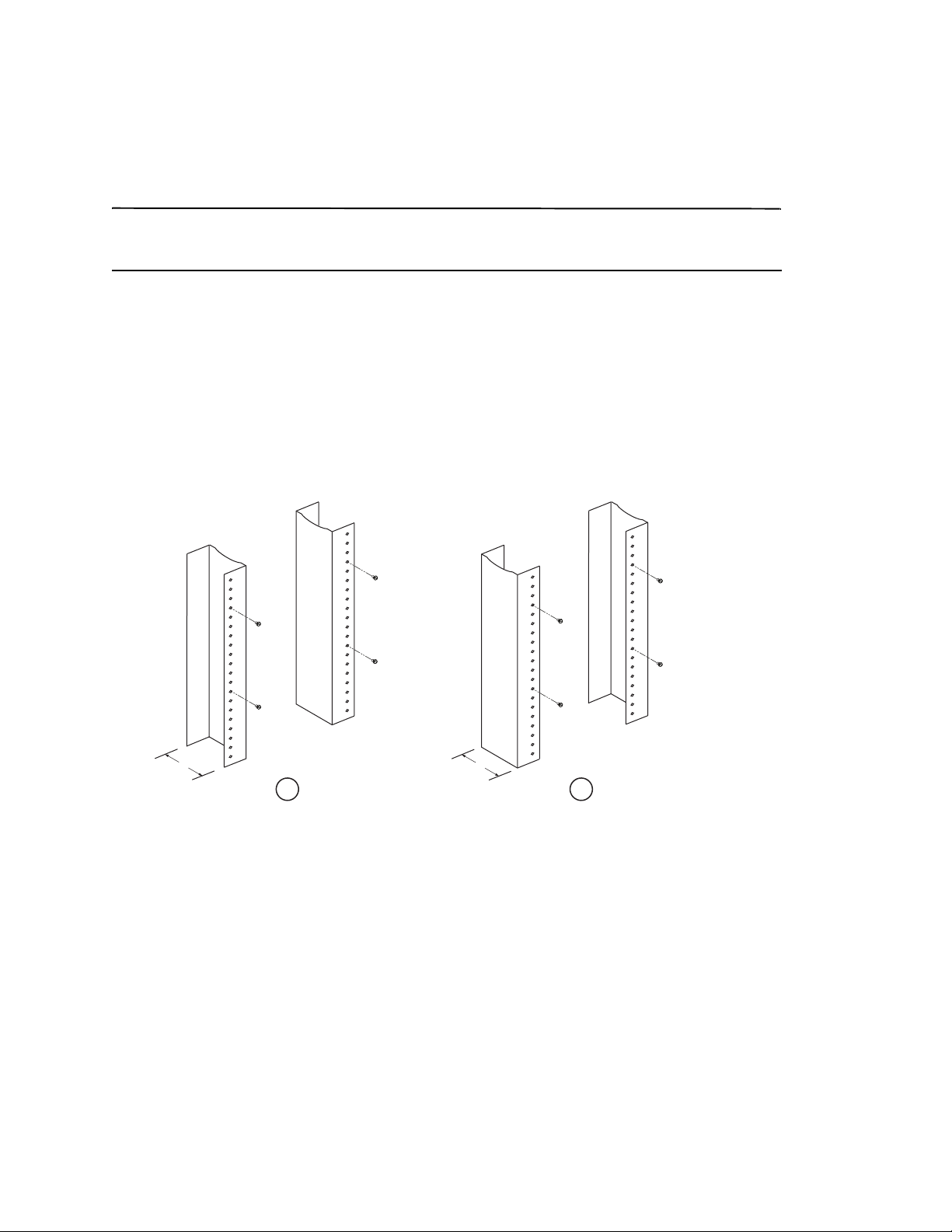
2. Using the keyhole slots in the chassis mounting brackets as a guide, align one screw per rack post, as shown in
Figure 5 on page 13. On one side of the rack, the screw should align with the top hole in the mounting bracket.
On the other side of the rack, the screw should align with the bottom hole of the mounting bracket. When
tightening these screws, leave approximately 1/4-inch of clearance between the back of the screw head and the
rack post.
FIGURE 5
1 Unequal flange equipment rack 2 Network equipment rack
Positioning the mounting screws in the rack posts
3. Starting with the chassis that will be in the lowest position in the rack, mount the chassis in the rack as shown in
the example of the 8-slot chassis in Figure 6. With two or more people lifting the chassis, slip the wide portion of
each keyhole slot over the corresponding mounting screw in the rack post.
PowerConnect B-MLXe Getting Started Guide 13
53-1001995-01
Page 16
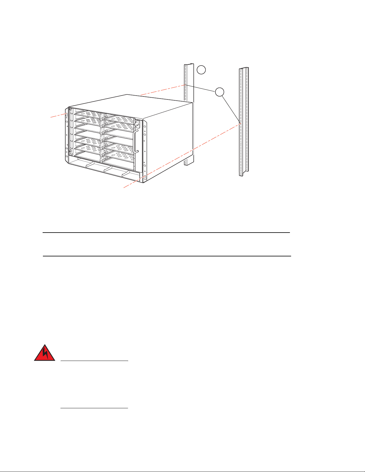
FIGURE 6
NOTE
DANGER
1
2
1 Equipment rack 2 Mounting holes
4. Slide the chassis down so that the mounting screw heads are in the narrow portion of the keyhole slots.
5. Tighten the screws to secure the chassis in place. For extra support, use additional screws.
Mounting the B-MLXe 8-slot chassis in a rack
For better grounding of the chassis to the rack, attach the chassis using star washers. You should also use star
washers with any single-hole grounding lugs to keep the lugs from rotating.
6. Repeat step 2 through step 5 to mount each chassis in the rack.
Installing modules
Use these procedures to install modules into empty slots. The same procedure applies to all modules.
The following sequence for installing multiple modules is important to ensure proper fit:
•
For the 4-slot and 8-slot chassis, install modules right-to-left, beginning with the lowest row and moving up.
•
For the 16-slot chassis, begin by filling the slots from the left side of the router, and work towards the right side.
The intra-building ports of the equipment or subassembly is suitable for connection to intra-building or
unexposed wiring or cabling only. The intra-building ports of the equipment or subassembly MUST NOT
be metallically connected to interfaces that connect to the outside plant (OSP) or its wiring. These
interfaces are designed for use as intra-building interfaces only (Type 2 or Type 4 ports as described in
GR-1089-CORE, Issue 4) and require isolation from the exposed OSP cabling. The addition of Primary
Protectors is not sufficient protection in order to connect these interfaces metallically to OSP wiring.
14 PowerConnect B-MLXe Getting Started Guide
53-1001995-01
Page 17
NOTE
The PowerConnect B-MLXe Series modules are dedicated, which means that you must install them in the
CAUTION
CAUTION
CAUTION
PowerConnect B-MLXe Series chassis only. For example, if you attempt to install the PowerConnect B-MLXe Series
management module in another Dell chassis or a management module intended for another Dell chassis in the
PowerConnect B-MLXe Series chassis, the chassis and module will not function properly.
Tab le 1 provides the chassis slot numbers into which you must install the modules. Markings for the chassis slots
appear at the base of the slots.
Each PowerConnect B-MLXe Series chassis ships with the required switch fabric modules installed.
TAB LE 1
PowerConnect B-MLXe Series module Chassis slot number
Management modules for 4-slot and 8-slot chassis
Management modules for 16-slot chassis
Interface modules for 4-slot chassis
Interface modules for 8-slot chassis
Interface modules for 16-slot chassis
Switch fabric modules for 4-slot and 8-slot chassis
Switch fabric modules for 16-slot chassis
PowerConnect B-MLXe module installation
Active module – M1 (left)
Redundant module – M2 (right)
Active module – M1 (upper)
Redundant module – M2 (lower)
1 – 4
1 – 8
1 – 16
SF1 – SF3
SF1 – SF4
Use of a power screwdriver may twist the heads from the screws and is not recommended.
If you do not install a module in a slot, you must keep the slot blank in place. If you operate
the chassis with an uncovered slot, the system may overheat. Tighten the screws that secure
the slot blanks so that they remain in place when removing adjacent panels or modules.
If you are hot-swapping a module, allow a minimum of two seconds after a module (or power
supply or fan tray) has been removed before inserting a module in the same slot.
If you are installing a redundant management module, refer to the appropriate configuration guide for your product
for information about how the redundant module works, optional software configurations that you can perform, and
how to manage the redundancy feature.
PowerConnect B-MLXe Getting Started Guide 15
53-1001995-01
Page 18
Before installing a module in the PowerConnect B-MLXe Series chassis, have the following on hand:
DANGER
NOTE
•
An ESD wrist strap with a plug for connection to the ESD connector on the PowerConnect B-MLXe Series chassis.
For safety reasons, the ESD wrist strap should contain a 1 megohm series resistor.
•
A large flat-head screwdriver.
Follow the steps given below to install a module in the PowerConnect B-MLXe Series chassis:
1. If you are installing a module in an empty slot that was not previously configured for a different module, go on to
step 2. If you are installing a module in a slot which may have been previously configured for a different module
type, remove the old configuration information using this procedure.
a. Use the show running-config command in config mode to determine the current configuration of the slot.
PowerConnect(config)# show running-config
Current configuration:
!
ver V5.0.0T163
module 1 ni-mlx-24-port-1g-copper
!
This example shows that slot 1 is currently configured for a 20-port 1 Gbps copper interface module.
b. With the module designation from show running-config command output, use the no module
<slot-number> <module-type> command to remove the configuration from slot 1.
PowerConnect(config)# no module 1 ni-mlx-20-port-1g-copper
This command removes the configuration from slot 1, leaving it ready for a new module.
2. Put on the ESD wrist strap and ground yourself by inserting the plug into the ESD connector on the chassis.
3. Remove the module from the packaging.
4. Insert the module into the slot, and slide the module along the card guide until the ejectors on either side of the
module rotate towards the module front panel.
When inserting a module in the chassis, make sure that the module faceplate does not overlap the faceplate of
an adjacent module.
5. Rotate the ejectors flush with the module faceplate. This action will fully seat the module in the backplane.
6. Tighten the two screws on the module faceplate by pushing them in and turning them clockwise. Complete the
tightening process using the flat-blade screwdriver.
7. E nt e r t he write memory command to ensure that the slot will be correctly configured for the new module after a
reboot.
PowerConnect(config)# write memory
Write startup-config done.
16 PowerConnect B-MLXe Getting Started Guide
53-1001995-01
Page 19
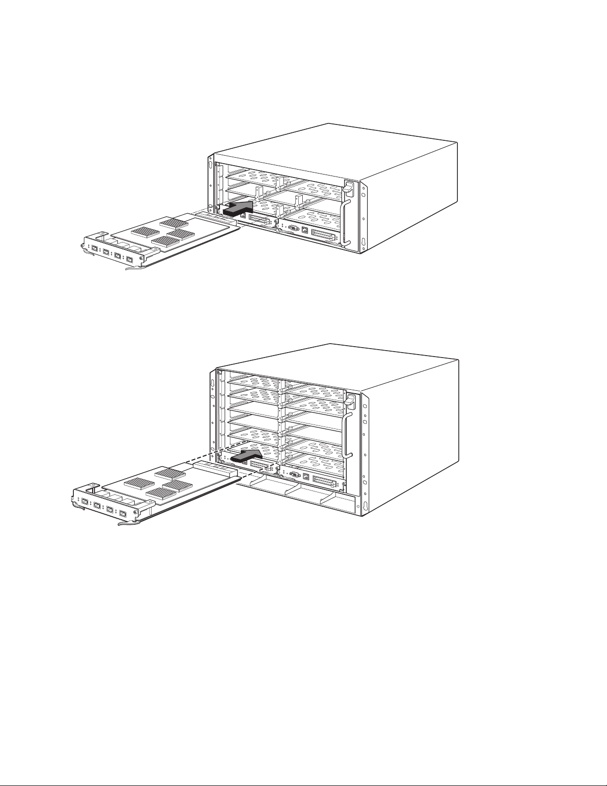
FIGURE 7
s
Installing a module in 4-slot chassis
FIGURE 8
Installing a module in an 8-slot chassis
PowerConnect B-MLXe Getting Started Guide 17
53-1001995-01
Page 20
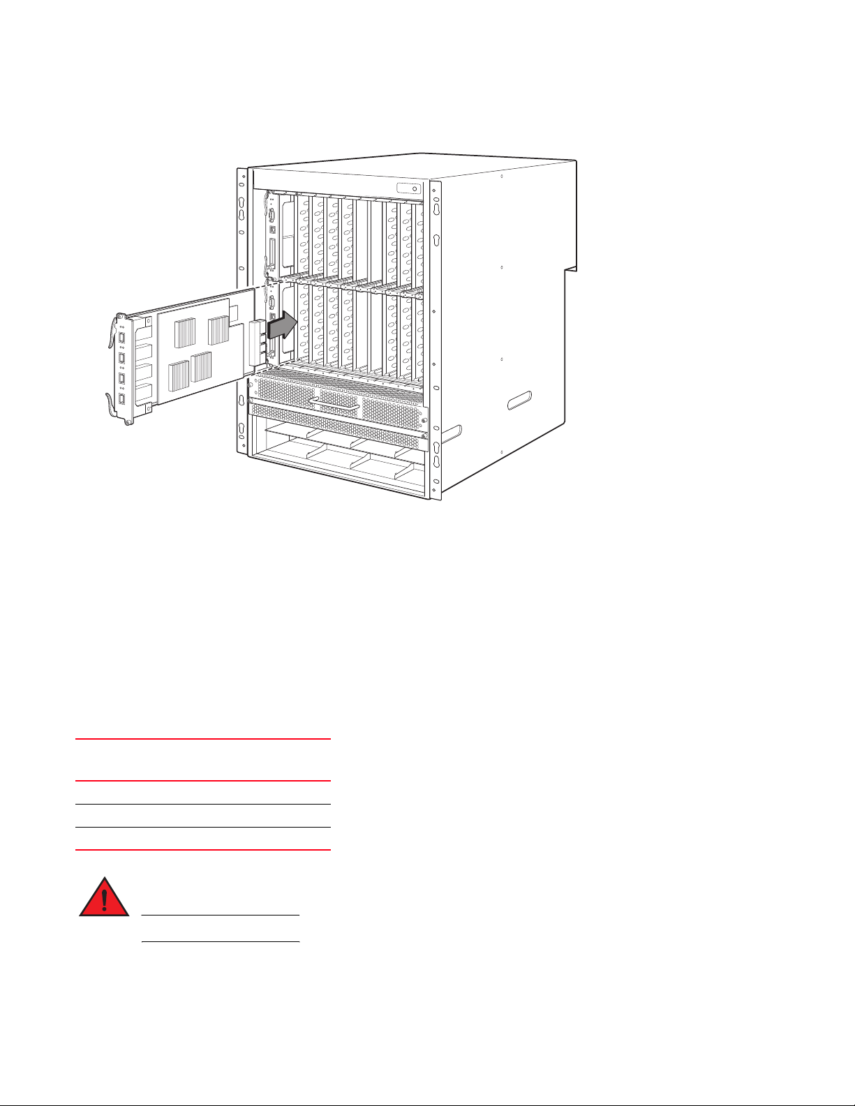
FIGURE 9
DANGER
Installing a module in a B-MLXe-16 chassis
Power supply, switch fabric, and fan requirements
For details on power supply, switch fabric, and fan requirements for modules installed in PowerConnect B-MLXe
Series units, refer to your hardware installation guide.
Installing power supplies
Tabl e 2 lists the number of power supplies (AC or DC) installed in the PowerConnect B-MLXe Series at the factory and
the maximum that you can install in each unit to add redundancy.
TABLE 2
Chassis Type Installed Power
4-slot 1 3
8-slot 2 4
16-slot 4 8
Power supplies for B-MLXe Series
Maximum
Supplies
High Touch Current. Earth connection is essential before connecting supply.
Power Supplies
Power supply installation steps
Follow these steps to install a power supply. You need a small Phillips or flat-head screwdriver to perform this task.
18 PowerConnect B-MLXe Getting Started Guide
53-1001995-01
Page 21
1. Remove the power supply slot blank.
CAUTION
CAUTION
Empty power supply slots must be covered with slot blanks.
2. Remove the power supply from the packaging.
3. Insert the power supply into the slot, using the guides on each side of the slot. Refer to Figure .
Carefully follow the mechanical guides on each side of the power supply slot and make sure the power
supply is properly inserted in the guides. Never insert the power supply upside down.
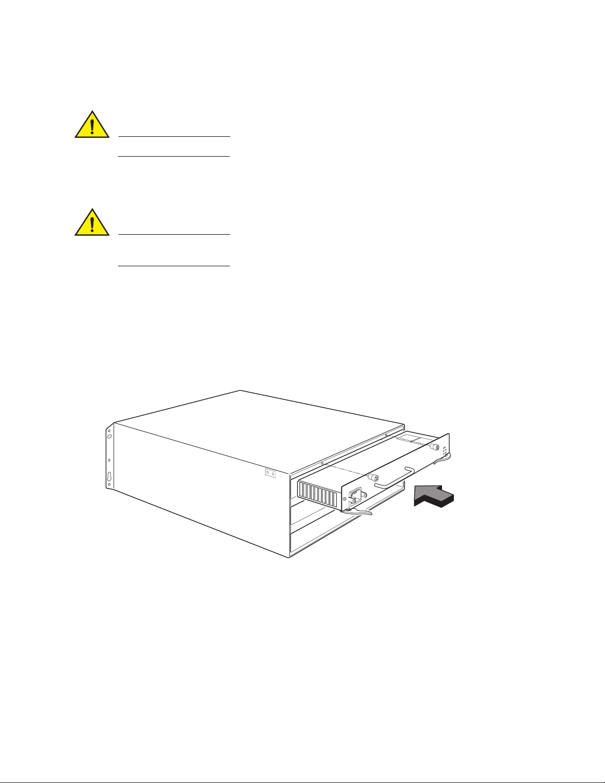
4. For the 4-slot chassis, follow these steps, then continue with step 6.
a. Push the power supply front panel into the router until it engages the backplane connector.
b. Rotate the ejector levers towards the front of the power supply to secure it in place.
c. Tighten the two screws on the power supply front panel by pushing them in and turning them clockwise.
Finish tightening the screws using the flat-blade screwdriver.
FIGURE 10
Installing a power supply in a 4-slot chassis
5. For the 8-slot and 16-slot chassis, follow these steps, then continue with step 6.
d. Slide the card along the card guide until fully inserted, then push the power supply front panel toward the
back of the chassis. This action causes the power supply connector to latch into the backplane connector.
e. Gently pull the handle on the power supply front panel upward and toward the top of the power supply front
panel. This action locks the power supply in place.
PowerConnect B-MLXe Getting Started Guide 19
53-1001995-01
Page 22
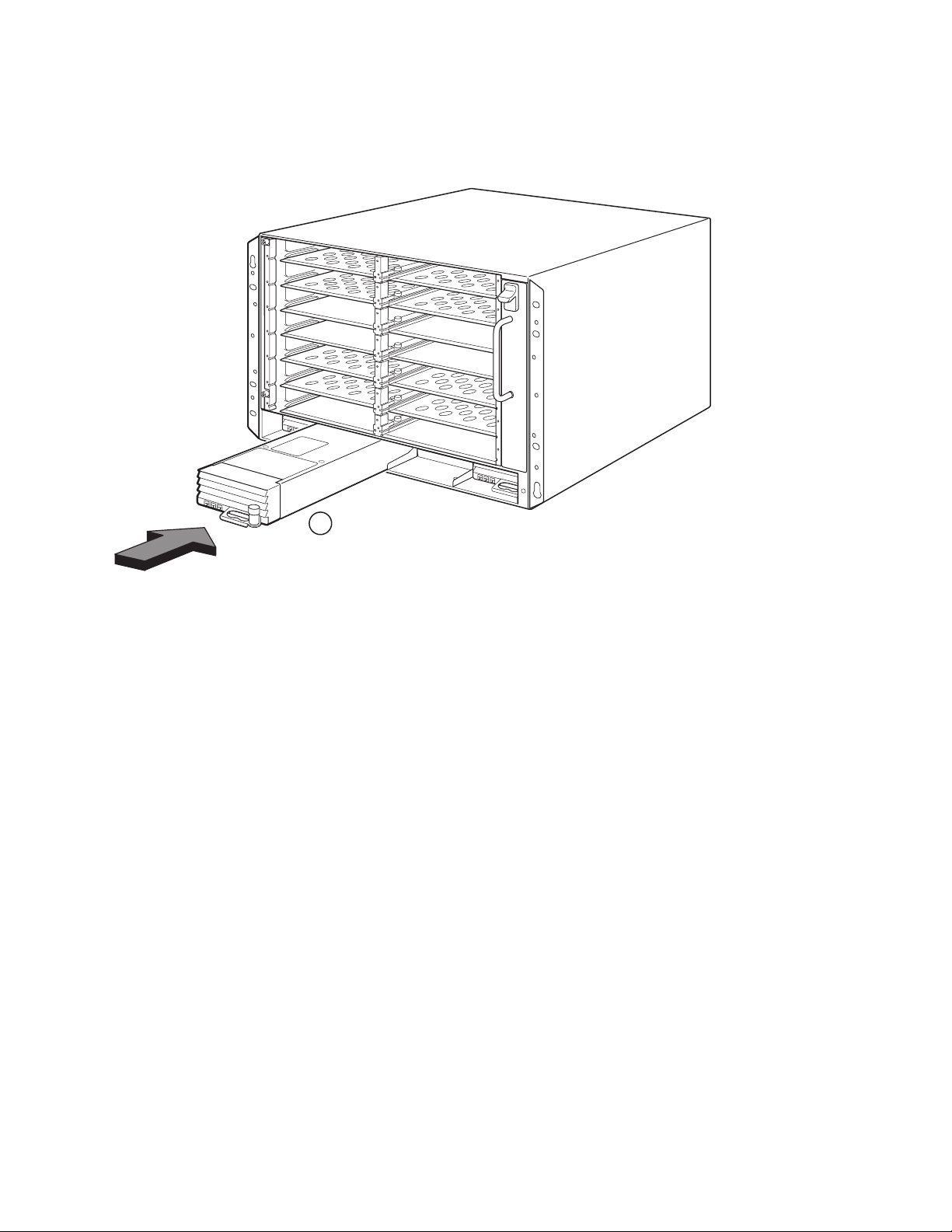
FIGURE 11
1
1 Power supply
Installing a power supply in an 8-slot chassis
20 PowerConnect B-MLXe Getting Started Guide
53-1001995-01
Page 23

FIGURE 12
1
2
Installing a power supply in a 16-slot chassis
1 Power supply 2 Release latch
6. For information about connecting power to the router, refer to “Connecting AC power” on page 21 or “Connecting
DC Power” on page 22.
7. For information about powering on the system, refer to “Activating the power source” on page 25.
Connecting AC power
AC power connection steps
1. Locate the power receptacles on the power supplies in the back panel of the B-MLXe chassis.
2. Lift the cord retainer and connect an AC power cord to the receptacle.
3. Snap the cord retainer over the power plug to hold it in place.
PowerConnect B-MLXe Getting Started Guide 21
53-1001995-01
Page 24
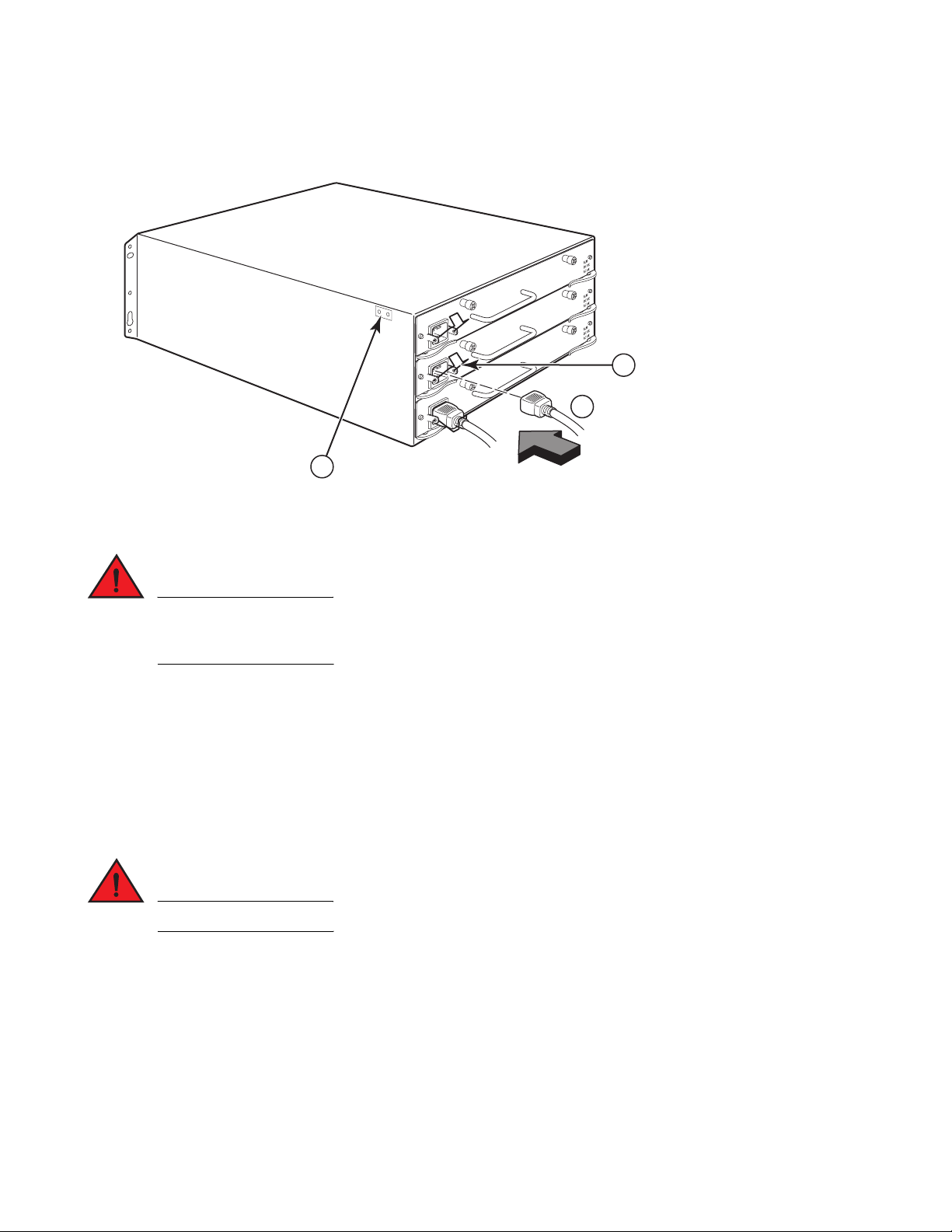
FIGURE 13
DANGER
DANGER
1
2
3
1 Ground point 2 Power Cord 3 Cord retainer
Example of connecting a power cord to an AC power supply installed in B-MLXe 4-slot chassis
If the installation requires a different power cord than the one supplied with the chassis, make sure you
use a power cord displaying the mark of the safety agency that defines the regulations for power cords in
your country. The mark is your assurance that the power cord can be used safely with the chassis.
4. For information about powering on the system, see “Activating the power source” on page 25.
Connecting DC Power
You can use a DC power source for the PowerConnect B-MLXe Series chassis. This is supported through use of a
DC-to-DC power supply. DC power must be supplied at 48 V and 30 A. The DC-to-DC supply provides the DC power to
the chassis at 12 V and 100 A.
The procedure in this section is for qualified service personnel.
Follow the steps given below to connect a DC power source.
1. Use a flat-blade screwdriver to remove the two screws holding the plastic cover over the power supply lugs.
22 PowerConnect B-MLXe Getting Started Guide
53-1001995-01
Page 25
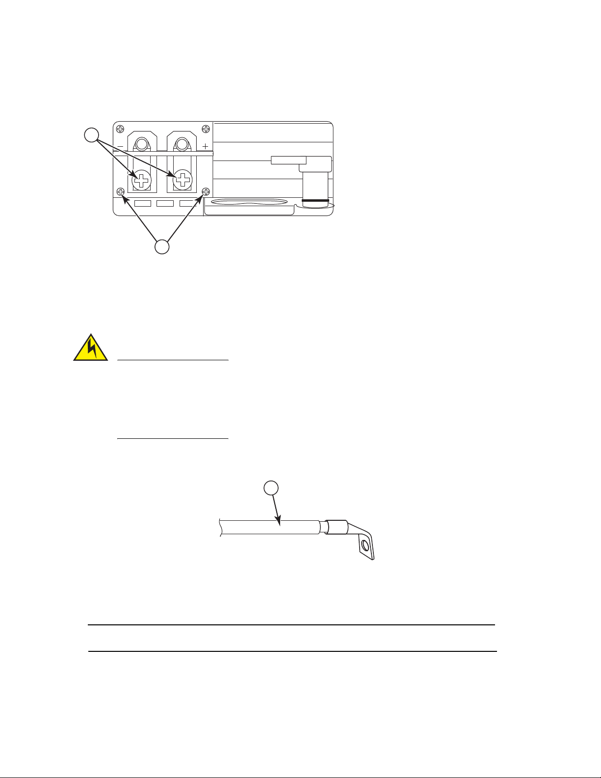
FIGURE 14
CAUTION
NOTE
1
DC power supply for the 8-slot and 16-slot chassis
2
DC IN
DC OUT
ALM
1
1 Screws holding plastic cover 2 Screws holding power lugs
2. Use a Phillips head screwdriver to remove each of the power lugs.
3. Crimp #8 AWG power supply wire into the power lugs and reconnect the power lugs to the power supply unit.
Refer to Figure 15.
For the NEBS compliant installation of a PowerConnect B-MLXe Series with AC and DC system use a
ground wire of at least 6 American Wire Gauge (AWG). The ground wire should have an agency-approved
crimped connector (provided with the chassis) attached to one end, with the other end attached to
building ground. The connector must be crimped with the proper tool, allowing it to be connected to both
ground screws on the enclosure. Before crimping the ground wire into the provided ground lug, ensure
the bare copper wire has been cleaned and antioxidant is applied to the bare wire.
FIGURE 15
1 #8 AWG power supply wire
Crimping the power supply wire in the lug
4. Re-attach the cover over the power supply lugs that was removed in step 1.
5. Connect the -48V cable to the negative terminal and the 0V cable to the positive terminal on the power supply.
DC return must be isolated from the router ground (DC-I) when connecting to the power supply.
This equipment installation must meet NEC/CEC code requirements. Consult local authorities for regulations.
PowerConnect B-MLXe Getting Started Guide 23
53-1001995-01
Page 26

Managing cables
NOTE
For information on managing cables attached to the PowerConnect B-MLXe Series, refer to your hardware
installation guide.
Attaching a management station
You can manage the PowerConnect B-MLXe Series system in the following ways:
•
You can connect a PC or terminal to the management module’s serial (Console) port for a direct connection.
From this interface, you can configure the 10BaseT/100BaseTX/1000BaseTX Ethernet (management) port with
an IP address and either Telnet or SSH. This enables you to manage the device through the
10BaseT/100BaseTX/1000BaseTX Ethernet (management) port using either Telnet or SSH.
•
You can connect the PowerConnect B-MLXe Series chassis to your existing management network and manage
the chassis, along with other network devices, from a management station. To do this, you can connect a
chassis to the management module’s 10BaseT/100BaseTX/1000BaseTX Ethernet (management) port.
The existing management network into which you can connect the 10/100 Ethernet port must be separate and
isolated from the network over which user packets are switched and routed.
For information about connecting a PC or terminal to the management module’s Console port or management port,
see “Attaching a PC or terminal to the Console port or Ethernet port,” next. For information about connecting a
management port to a network, see “Attaching the management module’s Ethernet Port to a network” on page 25.
Attaching a PC or terminal to the Console port or Ethernet port
The management module’s Console port (which has a male DB-9 serial connector), and 10BaseT/100Base TX
Ethernet port (which has an RJ-45 UTP connector) allow you to attach a PC or terminal. From the Console port, you
can access the PowerConnect B-MLXe Series chassis CLI directly from the PC or terminal or via a Telnet connection
to the PC or terminal. From the Ethernet port, you can access the PowerConnect B-MLXe Series CLI or Web
management interface directly from the PC or terminal or via a Telnet connection to the PC or terminal.
Before performing this task, you need the following items:
•
PC running a terminal emulation application or a terminal.
•
If connecting the PC or terminal to the Console port, a straight-through EIA/TIA DB-9 serial cable with one end
terminated in a female DB-9 connector and the other end terminated in a male or female DB-9 or DB-25
connector, depending on the specifications of your PC or terminal. You can order the serial cable separately from
Dell or build your own cable. If you prefer to build your own, see the pinout information in your hardware
installation guide.
•
If connecting the PC or terminal to the Ethernet port, a Category 5 UTP crossover cable, which you must supply.
For information about the management port pin assignments, refer to your hardware installation guide.
Follow the steps given below to attach a PC or terminal to the Console port or Ethernet port.
1. Connect a PC or terminal to the Console port or Ethernet port using the appropriate cable.
24 PowerConnect B-MLXe Getting Started Guide
53-1001995-01
Page 27
2. Open the terminal emulation program, and set the session parameters as follows:
CAUTION
DANGER
NOTE
NOTE
•
Baud: 9600 bps
•
Data bits: 8
•
Parity: None
•
Stop bits: 1
•
Flow control: None
Attaching the management module’s Ethernet Port to a network
The management module’s 10BaseT/100BaseTX/1000BaseTX Ethernet (management) port (RJ-45 UTP connector)
allows you to connect the management port to a network. A management station in your existing management
network can then access a PowerConnect B-MLXe Series chassis using the management application.
To attach the management module’s Ethernet port to a network, you need a Category 5 UTP straight-through cable
(not supplied by Dell). Connect one end of the straight-through cable to the management port and the other end to
the network.
Activating the power source
After you complete the hardware installation, you can power-on your power source.
1. Verify that all modules and power supplies are fully and properly installed and no module slots are uncovered.
If you do not install a module in a slot, you must keep the slot blank in place. If you run the chassis with
an uncovered slot, the system may overheat.
2. If your power source is AC, attach one end of a Dell-supplied AC power cord to the AC power supply as described
in “Connecting AC power” on page 21.
Insert the other end into a 115V or 120V wall outlet. Repeat this step for each installed AC power supply.
If the installation requires a different power cord than the one supplied with the device, make sure you
use a power cord displaying the mark of the safety agency that defines the regulations for power cords in
your country. The mark is your assurance that the power cord can be used safely with the device.
The PowerConnect B-MLXe Series chassis is designed to provide uninterrupted service even when you insert or
remove the management modules and the interface modules. Therefore, the system does not have a separate
on/off power switch. To turn the system off, simply unplug the power cords.
The wall outlet should be installed near the equipment and should be easily accessible.
PowerConnect B-MLXe Getting Started Guide 25
53-1001995-01
Page 28

3. If you are supplying a DC power source to a PowerConnect B-MLXe Series chassis, attach the power cables to
PowerConnect# show module
Module Status Ports Starting MAC
M1 (upper): NI-MLX-MR Mgmt Module Active
M2 (lower):
F0: NI-MLX-MR Switch Fabric Module Active
S1:
S2:
S3:
S4: NetIron 4-Port 10Gig Module CARD_STATE_UP 4 000c.db80.0000
S5: NetIron 4-Port 10Gig Module CARD_STATE_UP 4 000c.db80.0000
S6: NetIron 4-Port 10Gig Module CARD_STATE_UP 4 000c.db80.0000
S7:
the DC power supply as described in “Connecting DC Power” on page 22.
Connect the other end of the cables to the DC power source. Repeat this step for each installed DC power
supply. Then switch on the power source.
4. Verify that the PowerConnect B-MLXe Series chassis has initialized successfully. For information, see “Verifying
proper operation,” below.
Verifying proper operation
To verify the proper operation of the PowerConnect B-MLXe Series chassis after power on, you can do the following:
•
Observe the LEDs.
•
Display the status of the modules using the CLI.
Observing the LEDs
After a PowerConnect B-MLXe Series chassis powers on, you can observe its LEDs to verify that it initialized
successfully. Refer to your hardware installation guide for a complete description of LED operation and status
messages displayed through the CLI show module command.
If a problem persists, contact technical support.
Displaying the module status
After you have attached a PC or terminal to the management module’s Console or Ethernet port and the
PowerConnect B-MLXe Series chassis has initialized successfully, press Enter to display the following CLI prompt in
the terminal emulation window:
PowerConnect>
If you do not see this prompt, do the following:
1. Make sure the cable is securely connected to your PC or terminal and the Console port or Ethernet port.
2. Check the settings in your terminal emulation program. In addition to the session settings listed in “Attaching a
PC or terminal to the Console port or Ethernet port” on page 24, make sure the terminal emulation session is
running on the same serial port you attached to the Console port.
If you see this prompt (PowerConnect>), you are now connected to the system and can display the status of the
modules using the CLI. Enter the following command at any CLI level:
26 PowerConnect B-MLXe Getting Started Guide
53-1001995-01
Page 29

Assigning passwords
NOTE
NOTE
NOTE
By default, the PowerConnect B-MLXe Series CLI is not protected by passwords. To secure CLI access, Dell strongly
recommends assigning passwords.
The CLI contains the following access levels:
•
Privileged EXEC – This level is also called the Enable level and can be secured by a password. From this level you
can manage files on the management module flash memory or a PCMCIA flash card in the management module
slots 1 or 2, save the system configuration to flash memory, and clear caches.
•
CONFIG – The configuration level. This level lets you configure the system’s IP address and configure routing
features. To access the CONFIG mode, you must already be logged into the Privileged level of the EXEC mode.
You can set the following levels of Enable passwords:
•
Super User – Allows complete read-and-write access to the system. This is generally for system administrators
and is the only password level that allows you to configure passwords.
You must set a super user password before you can set other types of passwords.
•
Port Configuration – Allows read-and-write access for specific ports but not for global (system-wide) parameters.
•
Read Only – Allows access to the Privileged EXEC mode and CONFIG mode but only with read access.
To set passwords:
1. At the opening CLI prompt, enter the following command to change to the Privileged level of the EXEC mode:
PowerConnect> enable
PowerConnect#
2. Access the CONFIG level of the CLI by entering the following command:
PowerConnect# configure terminal
PowerConnect(config)#
3. Enter the following command to set the super-user password:
PowerConnect(config)# enable super-user-password <text>
You must set the super-user password before you can set other types of passwords.
4. Enter the following commands to set the port configuration and read-only passwords:
PowerConnect(config)# enable port-config-password <text>
PowerConnect(config)# enable read-only-password <text>
If you forget your super-user password, see the Release Notes.
The read-only--password and the port-config password should be difference from the super-user password.
Passwords can be up to 48 characters long.
PowerConnect B-MLXe Getting Started Guide 27
53-1001995-01
Page 30

Configuring IP addresses
The PowerConnect B-MLXe Series implement separate data and control planes. This architecture affects how you
assign IP addresses. Tabl e 3 outlines the interfaces to which you can assign IP addresses.
In this table, “in band” refers to an interface over which user packets are routed, while “out of band” refers to an
interface over which control packets related to system management are forwarded.
TABLE 3
Interface Associated physical port Out of band or in band
Assigning IP addresses
Management interface Ethernet 10/100/1000 port on active
or redundant management module
Any interface over which user packets are routed Any interface module port In band
Any virtual interface over which user packets are routed Any interface port In band
Loopback interface – In band
This section describes the following:
•
PowerConnect B-MLXe Series support of sub-net masks
•
How to assign an IP address to a management interface
•
How to assign an IP address to an interface or virtual interface over which user packets are routed
Out of band
Support of subnet masks
The PowerConnect B-MLXe Series supports both classical IP network masks (Class A, B, and C subnet masks, and so
on) and Classless Interdomain Routing (CIDR) network prefix masks.
•
To enter a classical network mask, enter the mask in IP address format. For example, enter
“209.157.22.99 255.255.255.0” for an IP address with a Class-C subnet mask.
•
To enter a prefix number for a network mask, enter a forward slash (/) and the number of bits in the mask
immediately after the IP address. For example, enter “209.157.22.99/24” for an IP address that has a network
mask with 24 significant (“mask”) bits.
Assigning an IP address to a management interface
Instead of assigning a global IP address to the B-MLXe for system management purposes, you must assign an IP
address to the active management module. If the active management module becomes unavailable and the
redundant module becomes the active module, the IP address is automatically assigned to the new active
management module.
For example, to assign the IP address 10.0.1.1 to the management interface, do the following:
1. At the opening CLI prompt, enter enable:
PowerConnect> enable
2. Enter the following command at the Privileged EXEC level prompt (for example, PowerConnect#), then press
Enter. This command erases the factory test configuration if still present:
PowerConnect# erase startup-config
28 PowerConnect B-MLXe Getting Started Guide
53-1001995-01
Page 31

CAUTION
Use the erase startup-config command only for new systems. If you enter this command on a system you
CAUTION
have already configured, the command erases the configuration. If you accidentally erase the
configuration on a configured system, enter the write memory command to save the running
configuration to the startup-config file.
3. Access the configuration level of the CLI by entering the following command:
PowerConnect# configure terminal Privileged EXEC Level
PowerConnect(config)# Global CONFIG Level
4. Configure the IP address and mask for the management interface by entering the following commands:
PowerConnect(config)# interface management 1
PowerConnect(config-if-mgmt-1)# ip address 10.0.1.1 255.255.255.0
Assigning an IP address to an interface, virtual interface, or loopback
You must assign an IP address to each interface and virtual interface over which user packets are routed. You can
also assign an IP address to a loopback interface, which is generally used for testing and diagnostic purposes. You
must use the serial connection to assign the first IP address. For subsequent addresses, you also can use the CLI
through Telnet or the Web management interface. By default, you can configure up to 24 IP interfaces on each
interface, virtual interface, and loopback interface.
For example, to assign IP address 192.22.3.44 and subnet mask 255.255.255.0 to Ethernet interface 1/1, do the
following.
1. At the opening CLI prompt, enter enable.
PowerConnect> enable
2. Enter the following command at the Privileged EXEC level prompt, then press Enter. This command erases the
factory test configuration if still present:
PowerConnect# erase startup-config
After you enter this command, you will need to restart the system.
Use the erase startup-config command only for new systems. If you enter this command on a system you
have already configured, the command erases the configuration. If you accidentally erase the
configuration on a configured system, enter the write memory command to save the running
configuration to the startup-config file.
3. Access the configuration level of the CLI by entering the following command:
PowerConnect# configure terminal
PowerConnect(config)#
PowerConnect B-MLXe Getting Started Guide 29
53-1001995-01
Page 32

4. Configure the IP address and sub-net mask for Ethernet interface 1/1 by entering the following commands:
PowerConnect(config)# interface ethernet 1/1
PowerConnect(config-if-e10000-1/1)# ip address 192.22.3.44 255.255.255.0
Use the secondary parameter if you have already configured an IP address within the same subnet on the interface.
Enabling and disabling the interfaces
By default, all B-MLXe interfaces are disabled. To enable an interface, enter the enable command at the appropriate
interface configuration level of the CLI. For example, to enable the management interface, enter the enable
command at the management interface configuration level of the CLI.
PowerConnect(config-if-mgmt-1)# enable
You can disable each of these interfaces using the disable command at the appropriate interface configuration level
of the CLI. For example, to disable the management port, enter the disable command at the management interface
configuration level of the CLI.
PowerConnect(config-if-mgmt-1)# disable
Connecting the PowerConnect B-MLXe Series to a network device
You can connect a PowerConnect B-MLXe Series chassis to another Ethernet network device. The PowerConnect
B-MLXe Series chassis supports connections to other vendors’ as well as Dell network devices.
Refer to your hardware installation guide for a description of the Ethernet interface modules available with the
PowerConnect B-MLXe Series. These include interface modules with XFP fiber, SFP and SFP+ fiber, and RJ-45
copper interfaces. Details regarding the SFP. SFP+, and XFP fiber-optic modules that are supported on these
interface modules are described in the hardware installation guide as well.
To connect a PowerConnect B-MLXe Series chassis to another network device, you must do the following:
•
Install the fiber-optic modules if required
•
Cable the modules with either copper cable or fiber optic cable as required
Refer to your hardware installation guide for information about performing these tasks, as well as cleaning the fiber
optic connectors and troubleshooting network connections.
30 PowerConnect B-MLXe Getting Started Guide
53-1001995-01
Page 33

Regulatory Notices
For additional regulatory information, see the Regulatory Compliance Homepage on www.dell.com at the following location:
www.dell.com/regulatory_compliance.
Información de la NOM (sólo para México)
La información que se proporciona a continuación aparece en el dispositivo descrito en este documento, en cumplimiento de los requisitos de la
Norma Oficial Mexican (NOM):
Importador: Dell Inc. de Mexico, S.A. de C.V.
Paseo de la Reforma 2620-11
Col. Lomas Altas
11950 Mexico, D.F.
Equipos portatiles
Modelo Voltaje de alimentación Frecuencia Consumo electrice
BI-RX-4 100-240 CA 50/60Hz 16A
BI-RX-8 100-240CA 50/60Hz 16A
BI-RX-16 100-240CA 50/60Hz 16A
MLXe-4 100-240CA 50/60Hz 16A
MLXe-8 100-240CA 50/60Hz 16A
MLXe-16 100-240CA 50/60Hz 16A
Brocade DCX-4S 100-240CA 50-60Hz 15A
Brocade 8000 100-240CA 47-63Hz 5-2.5A
Informação sobre Órgão Regulador
A marca de certificação se aplica a este Equipamento de Rede de Dados
Para maiores consultas sobre ANATEL visite o site: www.anatel.gov.br
o
Piso
PowerConnect B-MLXe Getting Started Guide 31
53-1001995-01
Page 34

32 PowerConnect B-MLXe Getting Started Guide
53-1001995-01
Page 35

53-1001995-01
53-1001995-01
2010 年 8 月 31 日
PowerConnect™ B-MLXe
系列
入门指南
53-1001995-01
*53-1001995-01*
Page 36

注、小心和警告
注
小心
警告
“注”表示有助于用户更好地使用计算机的重要信息。
“小心”表示不遵循说明可能导致硬件损坏或数据丢失。
“警告”表示可能导致财产损失、人身伤害或死亡。
____________________
本说明文件中的信息如有更改,恕不另行通知。
©2010DellInc. 版权所有,翻印必究。美国印制。
未经 Dell Inc. 书面许可,严禁以任何方式复制这些材料。
本文件中使用的商标: Dell、DELL 徽标、Inspiron、 Dell Precision、 Dimension、 OptiPlex、 Latitude、 PowerEdge、 PowerVault、PowerApp、
PowerConnect 以及 Dell OpenManage 是 Dell Inc. 的商标; Intel、 Pentium 和 Celeron 是 Intel Corporation 在美国和其他国家和地区的注册商
标; Microsoft、Windows、Windows Server、MS-DOS 和 Windows Vista 是 Microsoft Corporation 在美国和 / 或其他国家和地区的商标或注册
商标。
本说明文件中可能使用其他商标和商品名称来指拥有相应商标和商品名称的公司或其产品。 Dell Inc. 对不属于自己的商标和商品名称不拥有
任何所有权。
管制型号代码:MLXe-4, MLXe-8, MLXe-16
34 PowerConnect B-MLXe
入门指南
53-1001995-01
Page 37

本指南内容
• 简介 . . . . . . . . . . . . . . . . . . . . . . . . . . . . 35
• 安装所需的部件 . . . . . . . . . . . . . . . . . . . . . . . 39
• 场地规划及安全原则 . . . . . . . . . . . . . . . . . . . . . 40
• PowerConnect B-MLXe 系列的拆封 . . . . . . . . . . . . . . . 43
• 8 插槽和 16 插槽机箱的搬运指导 . . . . . . . . . . . . . . . 44
• 将机箱安装到机架上 . . . . . . . . . . . . . . . . . . . . . 45
• 安装模块 . . . . . . . . . . . . . . . . . . . . . . . . . . 46
• 安装电源设备 . . . . . . . . . . . . . . . . . . . . . . . . 50
• 连接交流电源 . . . . . . . . . . . . . . . . . . . . . . . . 53
• 连接直流电源 . . . . . . . . . . . . . . . . . . . . . . . . 54
• 管理线缆 . . . . . . . . . . . . . . . . . . . . . . . . . . 56
• 连接管理工作站 . . . . . . . . . . . . . . . . . . . . . . . 56
• 激活电源 . . . . . . . . . . . . . . . . . . . . . . . . . . 57
• 正常运行检验 . . . . . . . . . . . . . . . . . . . . . . . . 58
• 指定密码 . . . . . . . . . . . . . . . . . . . . . . . . . . 59
• 配置 IP 地址 . . . . . . . . . . . . . . . . . . . . . . . . 60
• 将 PowerConnect B-MLXe 系列连接到网络设备. . . . . . . . . . 62
简介
本指南提供如何对 PowerConnectB-MLXe 系列 4 插槽、 8 插槽和 16 插槽机箱作为独立单元进行拆封、安装和设
置的说明。请注意以下附加说明文件:
• 有关安装和配置详细说明,请参考适合该产品的硬件安装指南。
• 有关机架方面的安装说明,请参考合适的机架固定安装步骤。
PowerConnect B-MLXe 系列 4 插槽机箱(第 36 頁的图 1)和 8 插槽机箱 (第 37 頁的图 2)可通过下述方法来
安装:
• 作为平坦表面上的独立单元安装。
• 在 19 英寸电子工业协会标准机柜 (EIA310-D) 中安装。 B-MLXe 系列单元带有用于在机架上安装的内置固定
支架。
• 在中置安装电信 (Telco) 机架上安装。中置安装套件可以单独从 PowerConnect 供应商处订购,它可以将
PowerConnect 单元固定在机架中央。它包含两个 L 型的固定支架和支架及单元的安装指南。
PowerConnect B-MLXe 系列 16 插槽机箱 (第 38 頁的图 3)可用下述方法来安装:
• 在 19 英寸电子工业协会标准机柜 (EIA310-D) 中安装。 B-MLXe 系列单元带有用于在机架上安装的内置固定
支架。
• 在中置安装电信 (Telco) 机架上安装。中置安装套件可以单独从 PowerConnect 供应商处订购,它可以将
PowerConnect 单元固定在机架中央。它包含两个 L 型的固定支架和支架及单元的安装指南。
安装 PowerConnect B-MLXe 系列必需的基本配置步骤列于本指南中。硬件安装指南中会提供额外的配置信息。
PowerConnect B-MLXe
53-1001995-01
入门指南
35
Page 38

图 1 为 PowerConnect B-MLXe 系列 4 插槽机箱和组件位置的示意图。
图 1 PowerConnect B-MLXe 4 插槽机箱
1324
5
6
7
8910
1
接口插槽 2
2
交换结构插槽 2
3
交换结构插槽 3
4
ESD 接口
5
接口插槽 1
6
交换结构插槽 1
7
接口插槽 3
8
管理插槽 1
9
管理插槽 2
10
接口插槽 4
36 PowerConnect B-MLXe
53-1001995-01
入门指南
Page 39

图 2 为 PowerConnect B-MLXe 系列 8 插槽机箱和组件位置的示意图。
8
10
12
6
9
7
5
4
3
14 15
11
16 17
1 2
13
18
图 2 PowerConnect B-MLXe 8 插槽机箱
1
接口插槽 1
2
接口插槽 2
3
接口插槽 3
4
接口插槽 4
5
交换结构插槽 1
6
交换结构插槽 2
7
交换结构插槽 3
8
接口插槽 5
9
接口插槽 6
10
接口插槽 7
11
接口插槽 8
12
管理插槽 1
13
管理插槽 2
14
电源设备插槽 1
15
电源设备插槽 2
16
电源设备插槽 3
17
电源设备插槽 4
18
ESD 接口
PowerConnect B-MLXe
53-1001995-01
入门指南
37
Page 40

图 3 为 PowerConnect B-MLXe 系列 16 插槽机箱和组件位置的示意图。
图 3 PowerConnect B-MLXe 16 插槽机箱
3
1
5
7
17
19
91011
13
23
15
21
22
1-16
接口插槽 1-16
17
交换结构插槽 1
18
交换结构插槽 2
19
交换结构插槽 3
2
4
6
8
18
20
21
22
23
20
交换结构插槽 4
管理插槽 1
管理插槽 2
ESD 接口
12
14
16
38 PowerConnect B-MLXe
53-1001995-01
入门指南
Page 41

安装所需的部件
注
此文档说明如何设置 PowerConnect B-MLXe 系列 4 插槽、 8 插槽和 16 插槽机箱,以及如何用自带的支架将
其安装到 19 英寸设备机架上。如果要将机箱安装在机架中央,请从您的 PowerConnect 供应商处订购中置安装
套件。安装指南将随机架套件一同提供。本节将介绍 PowerConnect B-MLXe 系列随附的物品,以及安装所需的
物品。
产品随附的物品
产品随附下列物品:
• 4 插槽机箱出厂时已安装的组件:
- 两个高速交换结构模块。
- 每个闲置模块插槽上均装有空白插槽盖。空白插槽盖将没有安装模块的插槽覆盖起来,以确保
通风正常。
- 一个风扇托盘组件,位于路由器的右前方。有关风扇的详细信息,请参考您的硬件安装指南。
- 一个电源设备 (交流或直流)。
• 8 插槽机箱出厂时已安装的组件有:
- 两个高速交换结构模块。
- 每个闲置模块插槽上均装有空白插槽盖。空白插槽盖将没有安装模块的插槽覆盖起来,以确保
通风正常。
- 一个风扇托盘组件,位于路由器的右前方。有关风扇的详细信息,请参考您的硬件安装指南。
- 两个电源设备 (交流或直流)。
• 16 插槽机箱出厂时已安装的组件有:
- 三个高速交换结模块。
- 每个闲置模块插槽上均装有空白插槽盖。空白插槽盖将没有安装模块的插槽覆盖起来,以确保
通风正常。
- 一个风扇托盘组件,位于机箱右前方,而两个风扇组件位于机箱后方。有关风扇的详细信息,请参考您
的硬件安装指南。
- 四个电源设备 (交流或直流)。
• 质保卡。
• 每个购买自 Dell 的交流电源设备各配有一根 115V 交流电源线。
• Web 指示卡包含了软件映像和用户文档 (包括本指南在内)。
如有任何物品缺失,请与购买地点联系。
您必须自备的物品
• 组装好的 19 英寸电子工业协会标准机柜 (EIA310-D) 设备机架。
• 标准 12 - 24 号皿形头螺钉,用于将机箱安装到设备机架上。
• 2 号梅花槽螺丝刀。
• 大型平口螺丝刀。
• 中置安装机架套件 (可选)。请从您的 PowerConnect 供应商处订购。
• ESD 腕带,带插头以连接机箱上的 ESD 接口。
PowerConnect B-MLXe
53-1001995-01
入门指南
39
Page 42

场地规划及安全原则
注
警告
警告
小心
小心
请务必遵守下列步骤及安全预防措施,以确保正确地进行安装和操作。
场地规划
请遵循下列步骤以确保您的场地作好安装前准备。
布线结构
确保安装场地已完成了正确的布线。有关布线的信息,请参见您的硬件安装指南。
安装地点
安装机箱前,根据其他机器和设备相对于它的位置和朝向进行规划。为保证散热效果,应在两侧、前方以及后
方与墙面或其他障碍物间留出至少 15.24 厘米 (6 英寸)的空隙。如果要将机箱安装在表面开孔的机柜中,孔
的开口面积应至少为表面积的 60%。
PowerConnect B-MLXe 系列适用于安装在网络电信设施中,以及 NEC 要求适用的地方。此外它也可安装于公共
连接网 (CBN) 或隔离连接网 (IBN) 中。它不可用于外部线路设备 (OSP) 的安装。
安全原则
继续安装之前,请阅读适用于 PowerConnect B-MLXe 系列的 “小心”和 “警告”部分。
常规预防措施
本手册中的步骤适用于合格的维修人员。
所有光纤接口均使用了 1 类激光。
请不要将机箱安装在工作环境温度可能超过 40oC (104oF) 的环境中。
确定前方、侧面以及后方的通风均良好。
40 PowerConnect B-MLXe
53-1001995-01
入门指南
Page 43

小心
小心
电源预防措施
小心
警告
警告
警告
警告
警告
如果插槽中未安装模块,务必将空白插槽盖安装到位。如果工作中的机箱有未盖上的插
槽,系统可能会过热。
切勿将工具遗留在机箱中。
为每条交流电源线使用单独的分支线路形成冗余,预防某条线路发生故障。
根据机箱上安装的交流电源设备数量,确保选择了合适的线路设备。
将所有的电源线与电源断开以使机箱彻底断电。
确认电源线路接地良好,然后用随机箱提供的电源线将机箱连接到电源上。
如果安装要求使用非机箱自带的电源线,请确认您使用的电源线上印有您所在国家或地
区制定电源线规范的安全机构的标志。该标记是您的电源线可以安全地与机箱一同使用
的保证。
确认安装机箱的机架或机柜足够牢固,以免机箱松动或翻倒。
PowerConnect B-MLXe
53-1001995-01
入门指南
41
Page 44

警告
将机箱安装在机架或机柜中尽量低的位置。将最重的机箱安置于底层,再按轻重顺序逐
小心
小心
小心
小心
小心
个将较轻的单元安置于上层。
确保机箱不会使电源线路、配线及过流保护电路过载。要确定供电电路过载的可能性,
请将机箱所连接的线路上所有设备的额定电流 (安培数)相加。将这个总值与电路的限
额相比较。最大额定电流通常印在机箱上靠近电源输入接口的地方。
带直流电源的 B-MLXe 系列产品仅适用于安装在进出受限区域。进出受限区域是指只有维
护人员能够通过使用特殊工具、锁与钥匙或其他安全手段来进入的区域,由负责该区域
安全的管理机构来控制。
带交流电源的 B-MLXe 系列产品仅适用于安装在进出受限区域。进出受限区域是指只有维
护人员能够通过使用特殊工具、锁与钥匙或其他安全手段来进入的区域,由负责该区域
安全的管理机构来控制。
用于 16 插槽机箱的直流输入线路 (1800 瓦电源),确认在电源设备的输入接线片上有
通过 UL 认证最低 -48VDC 的 60 安培双极断路器。连接产品的输入线缆应为铜线 (6
AWG,带 VW-1 标记,最低额定温度 90οC)。
对于带交流或直流系统的 16 插槽机箱的兼容 NEBS 的安装,要使用至少 6 美国线规
(AWG) 的地线。地线应一端连接带有机构认证的压接连接器 (随设备提供),另一端连接
到建筑物地面上。连接器应当使用适合的工具进行压接,使其能够同时连接到机柜的两
个接地螺钉上。将地线压接到接地接线片上之前,请确保已清理了裸露的铜线,并在裸
线上涂覆了抗氧化剂。
42 PowerConnect B-MLXe
53-1001995-01
入门指南
Page 45

PowerConnect B-MLXe 系列的拆封
PowerConnect B-MLXe 系列是分为几个部分运输的。请仔细审核列于第 39 页上 “产品随附的物品”下的物品,
并对照装箱内容进行检验。如有任何物品缺失,请与购买地点联系。
从运输包装箱中取出您的 B-MLXe 机箱。将运输包装箱和包装材料保留,以待以后需要移动或运输机箱时使用。
将 PowerConnect B-MLXe 系列机箱安装到机架中
本节将介绍下列操作:
• “ 准备将机箱安装到机架上 ”
• “ 移除 4 插槽和 8 插槽机箱的运输螺钉 ”
• “8 插槽和 16 插槽机箱的搬运指导 ”
• “ 将机箱安装到机架上 ”
准备将机箱安装到机架上
由于一台满载的 PowerConnect B-MLXe 系列机箱非常沉重,如有必要, Dell 建议先将机箱安装到机架上,再安
装模块和交流电源设备。
在一个标准的 19 英寸 (EIA310-D) 机架上,您可以安装
• 最多十个 PowerConnect B-MLXe 系列 4 插槽机箱。
• 最多六个 PowerConnect B-MLXe 系列 8 插槽机箱。
• 最多三个 PowerConnect B-MLXe 系列 16 插槽机箱。
每一个安装在机架上的 PowerConnect B-MLXe 系列机箱都必须用四颗标准 12-24 号皿形头螺钉来安装和固定。
进行这项工作之前,应准备一个已装配好的机架和一把 2 号梅花槽螺丝刀。
PowerConnect B-MLXe
53-1001995-01
入门指南
43
Page 46
移除 4 插槽和 8 插槽机箱的运输螺钉
注
警告
3
1
2
PowerConnectB-MLXe 系列 4 插槽和 8 插槽单元运输时在机箱的右侧安装了两颗螺钉。这些螺钉固定着风扇托
盘,防止它在运输过程中损坏。在安装路由器前必须移除这些螺钉。图 4 第 44 頁的 为螺钉位置示意图。
需要用 2 号 梅花槽螺丝刀来移除这些螺钉。
图 4 移除 4 插槽和 8 插槽机箱的运输螺钉
1
前方
2
后方
3
运输螺钉
8 插槽和 16 插槽机箱的搬运指导
一台满配的 B-MLXe 16 插槽机箱是非常沉重的。必须两个人抬起、移动或安装这些设备。
请遵循下列原则来搬移 8 插槽或 16 插槽机箱:
• 在抬起或移动机箱前,断开所有的外部线缆。
• 请不要尝试一个人抬起满配的机箱。应有两个人来抬起机箱。
• 建议在将机箱安装到机架上之前先移除所有的机箱组件。
44 PowerConnect B-MLXe
入门指南
53-1001995-01
Page 47

将机箱安装到机架上
注
请遵循下列步骤将 PowerConnect B-MLXe 系列机箱安装到机架上。
您必须准备标准 12-24 号皿形螺钉将机箱安装到机架上。您需要一把梅花槽螺丝刀来进行这项工作。
1. 确定每个机箱在机架上的位置。例如,将模块最少的单元放置在机架的顶部,模块多一些的放置在中部,
满配的单元则放置在机架底部。
2. U 用机箱固定支架上的键孔槽作为参照,将每根机架杆上的螺钉一一对齐,如第 45 頁的图 5 中所示。在机
架的一侧,螺钉应当与固定支架的顶部孔对齐。在机架的另一侧,螺钉应当与固定支架的底部孔对齐。在
拧紧螺钉时,在螺钉头的背面与机架杆之间留出大约 1/4 英寸的空隙。
图 5 在机架杆上定位固定螺钉
1
非对称凸缘设备机架
5"
3"
1 2
2
网络设备机架
PowerConnect B-MLXe
53-1001995-01
入门指南
45
Page 48

3. 从将位于机架最低位置的机箱开始,按照图 6 中所示的 8 插槽机箱的例子将机箱安装到机架上。由两人或
注
警告
1
2
更多人抬起机箱,将每个键孔槽较宽的部分滑动到机架杆相应固定螺钉的上方。
图 6 在机架上安装 B-MLXe 8 插槽机箱
1
设备机架
4. 将机箱向下滑动,使固定螺钉头卡入键孔槽较窄的部分。
5. 拧紧螺钉,将机箱固定到位。如需更好的支撑,请安装额外的螺钉。
如需让机箱与机架有更佳的接地连接,在连接机箱时可使用星形垫圈。您还应当在任何单孔接地接线片上
使用星形垫圈以免接线片旋转。
6. 重复步骤 2 至步骤 5,将各机箱分别安装到机架上。
2
固定孔
安装模块
按此操作程序将模块安装至闲置的插槽。所有模块均采用相同的程序。
安装多个模块时务必采用以下顺序以确保安装到位:
• 对于 4 插槽和 8 插槽机箱,请以从右至左、从下往上的顺序安装模块。
• 对于 16 插槽机箱,顺序为从路由器的左侧开始,向右侧填充插槽。
设备或组件的内建端口仅适用于连接内建的隐蔽的配线或布线。设备或组件的内建端口不得与连接
外部线路设备 (OSP) 或其配线的接口有金属连接。这些接口只能做为内建接口使用 (如
GR-1089-CORE Issue 4 中描述的类型 2 或类型 4 端口)并需要与外露 OSP 布线隔离。增加的主保护
器并不足以防止这些接口与 OSP 线路发生金属连接。
46 PowerConnect B-MLXe
53-1001995-01
入门指南
Page 49

注
PowerConnectB-MLXe 系列为专用模块,因此其只能安装于 PowerConnect B-MLXe 系列机箱中。例如,如果您试
小心
小心
小心
警告
图将 PowerConnect B-MLXe 系列管理模块安装到另一款 Dell 机箱上,或将用于其他 Dell 机箱的管理模块安装到
PowerConnect B-MLXe 系列机箱中,则机箱和模块将不能正常运行。
表 1 提供了必须安装模块的机箱插槽号码。机箱插槽的标记将出现在插槽的底部。
每个 PowerConnect B-MLXe 系列机箱均附带安装了所需的交换结构模块。
表 1 PowerConnect B-MLXe 模块安装
PowerConnect B-MLXe 系列模块 机箱插槽号
适用于 4 插槽和 8 插槽机箱的管理模块
适用于 16 插槽机箱的管理模块
适用于 4 插槽机箱的接口模块
适用于 8 插槽机箱的接口模块
适用于 16 插槽机箱的接口模块
适用于 4 插槽和 8 插槽机箱的交换结构模块
适用于 16 插槽机箱的交换结构模块
不推荐使用电动螺丝刀,可能会使螺钉头变形。
如果插槽中未安装模块,务必将空白插槽盖安装到位。如果工作中的机箱有未盖上的插
槽,系统可能会过热。拧紧螺钉以固定空白插槽盖,以确保移动相邻的面板或模块时,
空白插槽盖不会受到影响。
活动模块 – M1 (左)
冗余模块 – M2 (右)
活动模块 – M1 (上)
冗余模块 – M2 (下)
1 – 4
1 – 8
1 – 16
SF1 – SF3
SF1 – SF4
热插拔模块时,移除模块 (或电源设备、风扇托盘)后至少等待 2 秒,才能将模块插入
插槽中。
如要安装冗余管理模块,请参阅产品相应的配置指南以获取相关信息,了解冗余模块的工作原理、可执行的软
件配置,以及如何管理冗余功能。
在将模块安装到 PowerConnect B-MLXe 系列机箱前,请准备以下物品:
• ESD 腕带,带插头以连接 PowerConnect B-MLXe 机箱上的 ESD 接口。
为了确保安全, ESD 腕带应含有 1 百万欧姆的串联电阻器。
• 大型平头螺丝刀。
PowerConnect B-MLXe
53-1001995-01
入门指南
47
Page 50

按照下面给出的步骤,将模块安装到 PowerConnect B-MLXe 系列机箱:
注
1. 如要将模块安装至此前未针对其他模块进行配置的闲置插槽,请转至步骤 2。如果要安装模块的插槽此前
已针对其他不同的模块类型进行过配置,按照以下步骤将已有的配置信息删除。
a. 在配置模式中,使用 show running-config 命令来确定插槽的当前配置。
PowerConnect(config)# show running-config
Current configuration:
!
ver V5.0.0T163
module 1 ni-mlx-24-port-1g-copper
!
上面的例子表示插槽 1 当前已针对 20 端口 的 1 Gbps 铜接口模块进行了配置。
b. 通过利用 show running-config 命令输出所提供的模块指定值,利用 no module <slot-number>
<module-type> 命令将配置从插槽 1 删除。
PowerConnect(config)# no module 1 ni-mlx-20-port-1g-copper
此命令将配置从插槽 1 删除,以供新的模块使用。
2. 戴上 ESD 腕带并将插头插入机箱上的 ESD 接口,以导去身上的静电。
3. 将模块从包装中取出。
4. 将模块插入插槽,并沿着插卡导向器滑动模块,直至模块两边的弹出器旋转至模块的前面板。
将模块插入到机箱时,确保模块的面板不会与相邻模块的面板重叠。
5. 旋转弹出器使其与模块面板齐平。此操作可使模块完全地与背板贴合。
6. 将模块面板上的两个螺钉推入并按顺时针方向拧紧。再使用平口螺丝刀完全拧紧螺钉。
7. 重新引导设备,输入 write memory 命令以确保插槽已针对新的模块进行了正确的配置。
PowerConnect(config)# write memory
Write startup-config done.
48 PowerConnect B-MLXe
53-1001995-01
入门指南
Page 51

图 7 在 4 插槽机箱中安装模块
图 8 在 8 插槽机箱中安装模块
PowerConnect B-MLXe
53-1001995-01
入门指南
49
Page 52

图 9 在 B-MLXe-16 机箱中安装模块
警告
电源设备、交换结构以及风扇要求
对于安装在 PowerConnect B-MLXe 系列设备上的模块,其电源设备、交换结构以及风扇要求的相关详细信息,
请参阅您的硬件安装指南。
安装电源设备
表 2 列出了出厂时 PowerConnect B-MLXe 系列中所安装电源设备 (AC 或 DC)的数量,以及为增加冗余单个设
备所能安装的最大数量。
表 2 B-MLXe 系列的电源设备
机箱类型 已安装电源设备最大电源设
备数
4 插槽
8 插槽
16 插槽
13
24
48
高接触电流。连接电源前必须先接地。
50 PowerConnect B-MLXe
53-1001995-01
入门指南
Page 53

电源设备安装步骤
小心
小心
按照以下步骤安装电源。要进行此操作,需要小型梅花槽或平头螺丝刀。
1. 移除电源设备的空白插槽盖。
闲置的电源设备插槽必须使用空白插槽盖进行保护。
2. 移除电源设备包装。
3. 利用插槽两边的导轨,将电源设备插入插槽。请参阅图 10。
小心的沿电源设备插槽两边的机械导轨进行操作,同时确保电源设备正确插入导轨。切勿将电源设
备倒着插入。
4. 对于 4 插槽机箱,执行以下步骤,然后再执行步骤 6。
a. 将电源设备前面板推入路由器中,直至其与背板连接器啮合。
b. 向电源设备的前方旋转弹出器拉杆,将其固定到位。
c. 将电源设备模块前面板上的两个螺钉推入并按顺时针方向拧紧。再使用平口螺丝刀完全拧紧螺钉。
图 10 在 4 插槽机箱中安装电源设备
5. 对于 8 插槽和 16 插槽机箱,执行以下步骤,然后再执行步骤 6。
a. 沿插卡导向器滑动插卡直至完全插入,然后向机箱后方推动电源设备的前面板。此操作将使电源设备连
接器锁定至背板接连器上。
b. 向上并向电源设备前面板的顶部轻拉电源设备前面板上的手柄。此操作将使电源设备锁定到位。
PowerConnect B-MLXe
53-1001995-01
入门指南
51
Page 54

图 11 为 8 插槽机箱安装电源设备
1
1
电源设备
52 PowerConnect B-MLXe
53-1001995-01
入门指南
Page 55

图 12 在 16 插槽机箱中安装电源设备
1
2
1
电源设备
2
释放闩锁
6. 有关将电源连接到路由的信息,请参阅第 53 页上 “连接交流电源”或第 54 页上 “连接直流电源”。
7. 有关系统供电的信息,请参阅第 57 页上 “激活电源”。
连接交流电源
交流电源连接步骤
1. 找到 B-MLXe 机箱背板上电源设备的电源插座。
2. 提起线缆定位器,并将交流电源线连接到插座。
3. 用线缆定位器将电源插头卡住,使其固定到位。
PowerConnect B-MLXe
53-1001995-01
入门指南
53
Page 56

图 13 示例:将电源线连接至安装于 B-MLXe 4 插槽机箱上的交流电源设备
警告
警告
2
1
3
1
接地点
2
电源线
3
线缆定位器
如果安装中需要使用到与机箱随附的电源线所不同的线缆,请确保您所使用的电源线标有安全认证
机构 (即规定了您所在国电源线管理规程的机构)的标记。此标记意味着您可以安全地将此电源线
用于您的机箱。
4. 有关系统供电的相关信息,请参阅第 57 页上 “激活电源”。
连接直流电源
您可以对 PowerConnect B-MLXe 系列机箱使用直流电源。使用 DC-DC 电源设备可支持该功能。所提供的直流电
源必须为 48 伏 /30 安。 DC-DC 电源为机箱提供的直流电源为 12 伏 /100 安。
本节中的流程和步骤只适用于合格的维修人员。
按照下列步骤连接直流电源。
1. 使用平口螺丝刀将两颗用于将塑料盖板固定在电源设备接线片上的螺钉卸下。
54 PowerConnect B-MLXe
53-1001995-01
入门指南
Page 57

图 14 适用于 8 插槽和 16 插槽机箱的直流电源设备
小心
注
1
2
DC IN
DC OUT
ALM
1
1 用于固定塑料盖板的螺钉 2 用于固定电源接线片的螺钉
2. 使用梅花槽螺丝刀将电源接头分别卸下。
3. 将 #8 AWG 电源设备线压接至电源接线片上,然后将电源接线片重新连接至电源设备单元。请参阅图 15。
为使带交流和直流系统的 PowerConnect B-MLXe 系列的安装能够符合 NEBS 规定,请使用至少为 6 美
国线规 (AWG)的接地线。此接地线一端应连接至有关机构认可的压接接口 (机箱已附带),另一
端则应接地。必须使用适当的工具来压接接头,使其能够连接至机柜上的任一螺钉。在将接地线压
接至所提供的接地接线片上前,请确保已对裸露的铜线进行清洁并使用了抗氧化剂。
图 15 将电源设备线压接在接线片上
1 #8 AWG 电源设备线
4. 将 步骤 1 中卸下的盖板重新连接在电源设备接线片上。
5. 将 -48V 线缆连接至电源设备的负极, 0V 线缆连接至正极。
当连接至电源设备时,直流回路必须与路由器地线 (DC-I) 断开。
设备的安装必须符合 NEC/CEC 条例的要求。请咨询当地的权威机构获取相关规定。
PowerConnect B-MLXe
53-1001995-01
入门指南
55
Page 58

管理线缆
注
有关管理连接到 PowerConnect B-MLXe 系列设备线缆的信息,请参阅硬件安装指南。
连接管理工作站
可采用以下方式管理 PowerConnect B-MLXe 系列的系统:
• 采用直接连接的方式,将 PC 或终端连接到管理模块串行(控制台)端口。通过此接口,您可以为
10BaseT/100BaseTX/1000BaseTX 以太网 (管理)端口配置 IP 地址,以及远程登录或 SSH。这使您能够通
过 10BaseT/100BaseTX/1000BaseTX 以太网 (管理)端口,利用远程登录或 SSH 来管理设备。
• 您还可将 PowerConnect B-MLXe 系列机箱连接到现有的管理网络,并通过管理工作站,管理机箱以及其他
网络设备。要进行此操作,您可以将机箱连接到管理模块的 10BaseT/100BaseTX/1000BaseTX 以太网
(管理)端口。
连接 10/100 以太网端口的现有管理网络必须与用户信息包进行交换和路由的网络分开并隔离。
有关将 PC 或终端连接到管理模块控制台端口或管理端口的信息,请接着参阅 “将 PC 或终端连接到控制台端口
或以太网端口”。有关将管理端口连接到网络的信息,请参阅第 57 页上 “将管理模块以太网端口连接到网
络”。
将 PC 或终端连接到控制台端口或以太网端口
管理模块控制台端口(含 DB-9 串行插头连接器),以及 10BaseT/100Base TX 以太网端口(含 RJ-45 UTP 连接
器)可支持对 PC 或终端的连接。通过控制台端口,您可以通过 PC 或终端直接访问 PowerConnect B-MLXe 系列
机箱命令行界面,或通过远程登录连接 PC 或终端。通过以太网端口,您可以通过 PC 或终端直接访问
PowerConnect B-MLXe 系列命令行界面 或 Web 管理接口,或通过远程登录连接 PC 或终端。
进行此操作前,您需要以下设备:
• 运行有终端模拟应用程序的 PC 或终端。
• 要将 PC 或终端连接到控制台端口,需要直通 EIA/TIA DB-9 串行电缆,其一端为 DB-9 内孔连接器,另一端
为 DB-9 或 DB-25 内孔或插头式连接器,取决于您 PC 或终端的规格。您可以自行制作,也可从 Dell 另行订
购此串行电缆。如果您选择自行制作,请参阅硬件安装指南上提供的插针输出信息。
• 如欲将 PC 或终端连接到以太网端口,须准备五类 UTP 交叉电缆。有关管理端口插针分配的信息,请参考您
的硬件安装指南。
按照以下给出的步骤将 PC 或终端连接到控制台端口或以太网端口。
1. 使用适用的电缆将 PC 或终端连接到控制台端口或以太网端口。
2. 打开终端模拟程序,并按以下方式设置会话参数:
• Baud: 9600 bps
• Data bits: 8
• Parity: None
• Stop bits: 1
• Flow control: None
56 PowerConnect B-MLXe
53-1001995-01
入门指南
Page 59

将管理模块以太网端口连接到网络
小心
警告
注
注
管理模块的 10BaseT/100BaseTX/1000BaseTX 以及网管理端口(RJ-45 UTP 连接器)支持将管理端口连接到网
络。此时在现有管理网络中的管理工作站可以利用管理应用程序访问 PowerConnect B-MLXe 系列机箱。
要将管理模块以太网端口连接到网络中,您需要五类 UTP 直通电缆 (Dell 未提供)。将直通电缆的一端连接到
管理端口,另一端连接到网络。
激活电源
在完成硬件安装后,您可以打开电源。
1. 确认所有模块和电源设备均安装到位,且所有模块插槽均已遮盖。
如有插槽未安装模块,则必须为插槽安装空白插槽盖。如果机箱运行时有插槽未遮盖,系统可能会
过热。
2. 如采用交流电源,请按照第 53 页上 “连接交流电源”中所述步骤将 Dell 所提供的交流电源线的一端连接
到交流电源设备。
将另一端插入 115V 或 120V 的壁式电源插座。重复此步骤,连接所有已安装的交流电源设备。
如果安装中需要使用到与设备随附的电源线所不同的线缆,请确保您所使用的电源线标有安全认证
机构 (即规定了您所在国电源线管理规程的机构)的标记。该标记是您的电源线可以安全地与设备
一同使用的保证。
PowerConnect B-MLXe 系列机箱专为不间断的服务所设计 (设置包括您插入或移除管理模块和接口模块
时)。因此,该系统没有单独的电源开关。要关闭系统,只需直接拔出电源线。
壁式电源插座应安装在设备附近且易于使用。
3. 如 PowerConnect B-MLXe 系列机箱采用直流电源,请按照第 54 页上 “连接直流电源”中所述步骤将电源线
缆连接到直流电源设备。
将电缆另一端连接至直流电源。重复此步骤,连接所有已安装的直流电源设备。开关位于电源上。
4. 确认 PowerConnect B-MLXe 系列机箱已成功完成初始化。相关信息,请参阅下面的 “正常运行检验” 。
PowerConnect B-MLXe
53-1001995-01
入门指南
57
Page 60

正常运行检验
PowerConnect# show module
Module Status Ports Starting MAC
M1 (upper): NI-MLX-MR Mgmt Module Active
M2 (lower):
F0: NI-MLX-MR Switch Fabric Module Active
S1:
S2:
S3:
S4: NetIron 4-Port 10Gig Module CARD_STATE_UP 4 000c.db80.0000
S5: NetIron 4-Port 10Gig Module CARD_STATE_UP 4 000c.db80.0000
S6: NetIron 4-Port 10Gig Module CARD_STATE_UP 4 000c.db80.0000
S7:
要验证 PowerConnect B-MLXe 系列机箱开机后是否正常运行,可进行如下操作:
• 观察 LED 指示灯。
• 使用命令行界面显示模块的状态。
观察 LED 指示灯
在 PowerConnect B-MLXe 系列机箱开机后,可通过观察其 LED 指示灯来确认其初始化是否成功。请参考您的硬
件安装指南,获取有关 LED 指示灯运行以及状态信息 (通过 CLI show module 命令显示)的完整说明。
如果问题仍然存在,请联系技术支持部门。
显示模块状态
当您将 PC 或终端连接到管理模块控制台或以太网端口,且 PowerConnect B-MLXe 系列机箱完成初始化后,按下
Enter,将在终端模拟窗口中显示以下命令行界面提示符:
PowerConnect>
如未看到此提示符,请执行以下操作:
1. 确认已将电缆牢固地连接到您的 PC 或终端,以及控制台端口或以太网端口。
2. 检查终端模拟程序的设置。除 第 56 页上 “将 PC 或终端连接到控制台端口或以太网端口” 中列出的会话设
置外,请确保终端模拟会话运行于已连接至控制台端口的同一串行端口上。
如看到提示符 (PowerConnect>),表示您目前已连接到系统,并可使用命令行界面显示模块状态。在任一命令行
界面层级下输入以下命令:
58 PowerConnect B-MLXe
入门指南
53-1001995-01
Page 61

指定密码
注
注
注
默认情况下, PowerConnect B-MLXe 系列 CLI 未使用密码保护。要保护 CLI 访问的安全, Dell 强烈建议指定密
码。
CLI 包含以下访问级别:
• Privileged EXEC – 该级别亦称为“启用”级别,并可使用密码进行保护。在此级别中,您可以对管理模块
插槽 1 或 2 中的管理模块快擦写存储器或 PCMCIA 闪存卡上的文件进行管理,将系统配置保存到快擦写存
储器,以及清空高速缓存。
• CONFIG – 配置级别。该级别可配置系统 IP 地址以及路由功能。要使用 CONFIG 模式,您必 须已登录到 EXEC
模式的 Privileged 级别。
您可以设置以下 “启用”密码级别:
• Super User (超级用户) – 可对系统进行完全的读写访问。此级别通常用于系统管理员,并且是唯一允许对
密码进行配置的密码等级。
在您设置其他类型的密码前,您必须先设置一个超级用户密码。
• Port Configuration (端口配置) – 允许指定端口的读写访问,但不支持全局 (系统范围内)参数。
• Read Only (只读) – 仅允许只读访问 Privileged EXEC 模式以及 CONFIG 模式。
要设置密码:
1. 在打开的 CLI 提示符中,输入以下命令以更改为 EXEC 模式的 Privileged 级别:
PowerConnect> enable
PowerConnect#
2. 输入以下命令访问 CLI 的 CONFIG 级别
PowerConnect# configure terminal
PowerConnect(config)#
3. 输入以下命令设置超级用户密码:
PowerConnect(config)# enable super-user-password <text>
在您设置其他密码类型前,您必须先设置超级用户密码。
4. 输入以下命令设置端口配置以及只读密码:
PowerConnect(config)# enable port-config-password <text>
PowerConnect(config)# enable read-only-password <text>
如果您忘记了您的超级用户密码,请参阅 《重新启动发行说明》。
read-only--password (只读密码) 和 port-config password (端口配置密码)应不同于 super-user
(超级用户)密码。密码最长可设置为 48 个字符。
PowerConnect B-MLXe
53-1001995-01
入门指南
59
Page 62

配置 IP 地址
PowerConnect B-MLXe 系列实施了分离的数据面和控制面。该体系结构将影响您的 IP 地址分配。表 3 概述了可
以为其分配 IP 地址的接口。
在此表格中,“带内 (in band)”指的是用户信息包所通过的接口,而 “带外 (out of band)”指的是与系统管理相
关的控制信息包传输所通过的接口。
表 3 IP 地址分配
接口 相关物理端口 带外或带内
管理接口 已激活或冗余管理模块上的以太网
10/100/1000 端口
用户信息包所路由通过的任一接口 任一接口模块端口 带内
用户信息包所路由通过的任一虚拟接口 任一接口端口 带内
回送接口
本节就以下内容进行说明:
–
带外
带内
• PowerConnect B-MLXe 系列支持的子网掩码
• 如何为管理接口分配 IP 地址
• 如何为用户信息包所路由通过的接口或虚拟接口分配 IP 地址
支持的子网掩码
PowerConnect B-MLXe 系列同时支持标准的 IP 网络掩码(A、 B、 C 类子网掩码等)以及无类别域间路由 (CIDR)
网络前缀掩码。
• 要输入传统网络掩码,则以 IP 地址的格式输入掩码。例如,输入 “209.157.22.99 255.255.255.0”, 代表
一个含 C 类子网掩码的 IP 地址。
• 要为网络掩码输入前缀号码,紧随 IP 地址后输入正斜线 (/) 以及掩码的位数。例如,输入
“209.157.22.99/24”代表一个含 24 位有效 (“ 掩码”)位数网络掩码的 IP 地址。
为管理接口分配 IP 地址
与为进行系统管理而将全局 IP 地址分配到 B-MLXe 不同,您必须为激活的管理模块分配 IP 地址。当原有的激活
管理模块变为不可用,而冗余模块转而成为激活模块时, IP 地址将自动分配给新的激活管理模块。
例如,要将 IP 地址 10.0.1.1 分配给管理接口,请执行以下操作:
1. 在 CLI 提示符中,输入 enable:
PowerConnect> enable
2. 在 Privileged EXEC 级别提示符中输入以下命令 (例如, PowerConnect#), 然后按下 Enter。此命令将擦除
残留的工出厂测试配置:
PowerConnect# erase startup-config
60 PowerConnect B-MLXe
入门指南
53-1001995-01
Page 63

小心
只可在新系统上使用 erase startup-config 命令。如果在您已配置的系统中输入此命令,您的配置将
小心
被擦除。如果意外地擦除了系统中的已配置信息,输入写入存储器命令,将运行中的配置保存至启
动配置文件。
3. 输入以下命令访问 CLI 的配置级别:
PowerConnect# configure terminal Privileged EXEC Level
PowerConnect(config)# Global CONFIG Level
4. 输入以下命令为管理接口配置 IP 地址和掩码:
PowerConnect(config)# interface management 1
PowerConnect(config-if-mgmt-1)# ip address 10.0.1.1 255.255.255.0
为接口、虚拟接口或回路分配 IP 地址
必须为用户信息包所路由通过的各个接口和虚拟接口分配 IP 地址。也可为回送接口分配 IP 地址,此举通常用于
测试或诊断目的。您必须使用串行连接来分配首个 IP 地址。对于后续的地址,可以通过远程登录或 Web 管理接
口,使用 CLI 来进行分配。默认情况下,您最多可为每个接口、虚拟接口和回送接口配置 24 个 IP 接口。
例如,要将 IP 地址 192.22.3.44 和子网掩码 255.255.255.0 分配至以及网接口 1/1,请执行以下操作。
1. 在打开的 CLI 提示符中,输入 enable。
PowerConnect> enable
2. 在 Privileged EXEC 级别提示符中输入如下命令,然后按下 Enter。此命令将擦除残留的工出厂测试配置:
PowerConnect# erase startup-config
输入此命令后,您需要重新启动系统。
只可在新系统上使用 erase startup-config 命令。如果在您已配置的系统中输入此命令,您的配置将
被擦除。如果意外地擦除了系统中的已配置信息,输入写入存储器命令,将运行中的配置保存至启
动配置文件。
3. 输入以下命令访问 CLI 的配置级别:
PowerConnect# configure terminal
PowerConnect(config)#
4. 输入以下命令为以太网接口 1/1 配置 IP 地址和子网掩码:
PowerConnect(config)# interface ethernet 1/1
PowerConnect(config-if-e10000-1/1)# ip address 192.22.3.44 255.255.255.0
如果您已经在接口上的同一子网中配置了 IP 地址,请使用辅助参数。
PowerConnect B-MLXe
53-1001995-01
入门指南
61
Page 64

启用或禁用接口
默认情况下, B-MLXe 所有的接口均为禁用。要启用接口,在 CLI 相应的接口配置级中输入 enable 命令。例如,
要启用管理接口,在 CLI 管理接口配置级别中输入 enable 命令。
PowerConnect(config-if-mgmt-1)# enable
您可在相应的 CLI 接口配置级别中使用 disable 命令来禁用接口。例如,要禁用管理接口,在 CLI 管理接口配置
级别中输入 disable 命令。
PowerConnect(config-if-mgmt-1)# disable
将 PowerConnect B-MLXe 系列连接到网络设备
可以将 PowerConnect B-MLXe 系列机箱连接到另一以太网网络设备。PowerConnect B-MLXe 系列机箱支持与 Dell
以及其他供应商网络设备的连接。
参阅您的硬件安装指南,获取有关 PowerConnect B-MLXe 系列上可用的以太网接口模块的说明。包括含 XFP、
SFP 和 SFP+ 光纤以及 RJ-45 铜接口的接口模块。有关这些接口模块所支持的 SFP、 SFP+ 以及 XFP 光纤模块的
详细信息,也已在硬件安装指南中进行了说明。
要将 PowerConnect B-MLXe 系列机箱连接到另一网络设备,必须进行以下操作:
• 根据需要,安装光纤模块
• 按照要求,用铜电缆或光纤电缆将模块连接
请参阅您的硬件安装指南,获取此操作的相关信息,同时清洁光纤接头并排除网络连接中可能的故障。
管制通告
有关其他管制信息,请访问 www.dell.com 上的 “规章符合性”主页,网址为: www.dell.com/regulatory_compliance。
Información de la NOM (sólo para México)
La información que se proporciona a continuación aparece en el dispositivo descrito en este documento, en cumplimiento de los requisitos de la
Norma Oficial Mexican (NOM):
Importador: Dell Inc. de México, S.A. de C.V.
Paseo de la Reforma 2620-11
Col. Lomas Altas
11950 México, D.F.
Equipos portátiles
Modelo Voltaje de alimentación Frecuencia Consumo eléctrico
BI-RX-4 100-240CA 50/60Hz 16A
BI-RX-8 100-240CA 50/60Hz 16A
BI-RX-16 100-240CA 50/60Hz 16A
MLXe-4 100-240CA 50/60Hz 16A
MLXe-8 100-240CA 50/60Hz 16A
MLXe-16 100-240CA 50/60Hz 16A
Brocade DCX-4S 100-240CA 50-60Hz 15A
Brocade 8000 100-240CA 47-63Hz 5-2.5A
o
Piso
Informação sobre Órgão Regulador
A marca de certificação se aplica a este Equipamento de Rede de Dados
Para maiores consultas sobre ANATEL visite o site: www.anatel.gov.br
62 PowerConnect B-MLXe
53-1001995-01
入门指南
Page 65

53-1001995-01
2010 年 8 月 31 日
PowerConnect™ B-MLXe
系列
使用說明指南
53-1001995-01
*53-1001995-01*
Page 66

註、警示與警告
註
警示
危險
「註」是表示能幫助您更好使用電腦的資訊。
「警示」表示在未遵照指示時,有可能會損壞硬體或導致資料遺失。
「危險」表示有可能會導致財產損失、造成人員傷害或死亡。
____________________
本文件中的資訊如有變更,恕不另行通知。
©2010DellInc.版權所有,翻印必究。 美國印製。
未經 Dell Inc. 的書面許可,不得以任何形式進行複製。
本文件中使用的商標: Dell、DELL 徽標、Inspiron、Dell Precision、Dimension、OptiPlex、Latitude、PowerEdge、PowerVault、PowerApp、
PowerConnect 與 Dell OpenManage 是 Dell Inc. 的商標;Intel、Pentium 和 Celeron 是 Intel Corporation 在美國和其他國家的的註冊商標;
Microsoft、Windows、 Windows Server、 MS-DOS 與 Windows Vista 是 Microsoft Corporation 在美國和╱或其他國家的商標或註冊商標。
本文件中使用的其它商標與商品名稱是指擁有這些標誌及名稱的公司或其產品。 Dell Inc. 對於不屬於其本身的商品與名稱將不擁有任何專有
權益。
管制機型代碼:MLXe-4、MLXe-8、MLXe-16
64 PowerConnect B-MLXe
使用說明指南
53-1001995-01
Page 67

本指南中
• 本指南中 . . . . . . . . . . . . . . . . . . . . . . . . . . 65
• 簡介 . . . . . . . . . . . . . . . . . . . . . . . . . . . . 65
• 安裝所需項目 . . . . . . . . . . . . . . . . . . . . . . . . 69
• 場地規劃和安全指南 . . . . . . . . . . . . . . . . . . . . . 70
• 打開 PowerConnect B-MLXe 系列的包裝. . . . . . . . . . . . . 72
• 將 PowerConnect B-MLXe 系列機箱安裝在機架上. . . . . . . . . 73
• 安裝模組 . . . . . . . . . . . . . . . . . . . . . . . . . . 75
• 安裝電源供應器 . . . . . . . . . . . . . . . . . . . . . . . 79
• 連接交流電源 . . . . . . . . . . . . . . . . . . . . . . . . 81
• 連接直流電源 . . . . . . . . . . . . . . . . . . . . . . . . 82
• 管理纜線 . . . . . . . . . . . . . . . . . . . . . . . . . . 84
• 安裝管理工作站 . . . . . . . . . . . . . . . . . . . . . . . 84
• 啟動電源 . . . . . . . . . . . . . . . . . . . . . . . . . . 85
• 確認運作是否正常 . . . . . . . . . . . . . . . . . . . . . . 86
• 指定密碼 . . . . . . . . . . . . . . . . . . . . . . . . . . 86
• 設定 IP 位址 . . . . . . . . . . . . . . . . . . . . . . . . 87
• 連接 PowerConnect B-MLXe 系列和網路裝置. . . . . . . . . . . 90
簡介
本指南說明拆封、安裝及設定 PowerConnect B-MLXe 系列 4 插槽、8 插槽 及 16 插槽機箱 ( 作為獨立裝置 ) 的相
關程序。另請留意下列其他說明文件:
• 如需詳細安裝與設定說明,請參閱本產品相應的硬體安裝指南。
• 若是特定機架安裝說明,請參閱相應的機架安裝程序。
PowerConnect B-MLXe 系列 4 插槽機箱 ( 第 66 頁的圖 1) 和 8 插槽機箱 ( 第 67 頁的圖 2) 可依下列方式安裝:
• 安裝在平坦表面上作為獨立裝置。
• 安裝在 19 吋的電子工業協會機櫃中 (EIA310-D)。本 B-MLXe 系列裝置內建安裝在機架上的專用裝設托架。
• 安裝在中置式電信 (Telco) 機架上。中置式套件可另外向 PowerConnect 供應商訂購,並將 PowerConnect 裝
置置中裝設在機架上。此套件包含兩個 L 型裝設托架,以及安裝托架和裝設本裝置的說明。
PowerConnect B-MLXe 系列 16 插槽機箱 ( 第 68 頁的圖 3) 可依下列方式安裝:
• 安裝在 19 吋的電子工業協會機櫃中 (EIA310-D)。本 B-MLXe 系列裝置內建安裝在機架上的專用裝設托架。
• 安裝在中置式電信 (Telco) 機架上。中置式套件可另外向 PowerConnect 供應商訂購,並將 PowerConnect 裝
置置中裝設在機架上。此套件包含兩個 L 型裝設托架,以及安裝托架和裝設本裝置的說明。
PowerConnect B-MLXe
53-1001995-01
使用說明指南
65
Page 68

本指南列出設定 PowerConnect B-MLXe 系列時所需的基本設定步驟。其他設定資訊請參閱硬體安裝指南。
圖 1 說明 PowerConnect B-MLXe 系列 4 插槽機箱與元件位置。
圖 1 PowerConnect B-MLXe 4 插槽機箱
1324
5
6
7
8910
1
介面插槽 2
2
交換核心插槽 2
3
交換核心插槽 3
4
ESD 連接器
5
介面插槽 1
6
交換核心插槽 1
7
介面插槽 3
8
管理插槽 1
9
管理插槽 2
10
介面插槽 4
66 PowerConnect B-MLXe
53-1001995-01
使用說明指南
Page 69

圖 2 說明 PowerConnect B-MLXe 系列 8 插槽機箱和元件位置。
8
10
12
6
9
7
5
4
3
14 15
11
16 17
1 2
13
18
圖 2 PowerConnect B-MLXe 8 插槽機箱
1
介面卡插槽 1
2
介面插槽 2
3
介面插槽 3
4
介面插槽 4
5
交換核心插槽 1
6
交換核心插槽 2
7
交換核心插槽 3
8
介面插槽 5
9
介面插槽 6
10
介面插槽 7
11
介面插槽 8
12
管理插槽 1
13
管理插槽 2
14
電源供應器插槽 1
15
電源供應器插槽 2
16
電流供應器插槽 3
17
電源供應器插槽 4
18
ESD 連接器
PowerConnect B-MLXe
53-1001995-01
使用說明指南
67
Page 70
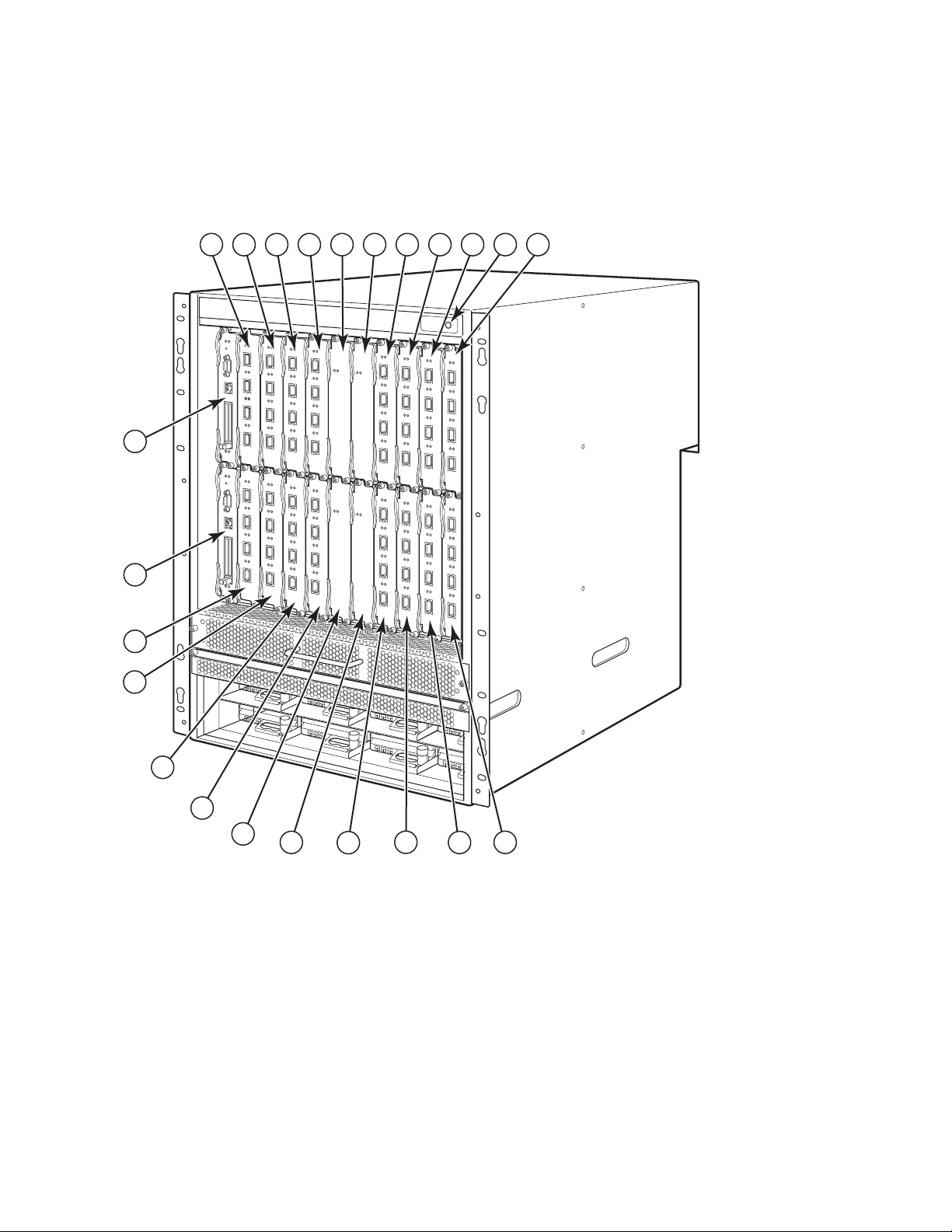
圖 3 說明 PowerConnectB-MLXe 系列 16 插槽機箱和元件的位置。
圖 3 PowerConnect B-MLXe 16 插槽機箱
3
1
5
7
17
19
91011
13
23
21
22
15
1-16
介面插槽 1-16
17
交換核心插槽 1
18
交換核心插槽 2
19
交換核心插槽 3
2
4
6
8
18
20
21
22
23
20
交換核心插槽 4
管理插槽 1
管理插槽 2
ESD 連接器
12
14
16
68 PowerConnect B-MLXe
53-1001995-01
使用說明指南
Page 71

安裝所需項目
註
本文件說明如何安裝 PowerConnect B-MLXe 系列 4 插槽、8 插槽及 16 插槽機箱,並使用各機箱內建的托架裝設
在 19 吋的設備機架上。若要將機箱置中裝設在機架上,請向 PowerConnect 供應商訂購中置式機架套件。機架
套件中會隨附安裝說明。本節說明 PowerConnect B-MLXe 系列的隨附項目以及安裝時的所需項目。
裝置隨附項目
以下為裝置隨附項目:
• 4 插槽機箱會隨附下列安裝用元件:
- 兩個高速交換核心模組。
- 各空白模組插槽上的插槽蓋 (slot blank)。插槽蓋會裝設在目前未安裝模組的插槽上,確保通風良好。
- 風扇組,位於路由器右前方。如需有關風扇的詳細資訊,請參閱硬體安裝指南。
- 電源供應器 ( 交流電或直流電 )。
• 8 插槽機箱會隨附下列安裝用元件:
- 兩個高速交換核心模組。
- 各空白模組插槽上的插槽蓋。插槽蓋會裝設在目前未安裝模組的插槽上,確保通風良好。
- 風扇組,位於路由器右前方。如需有關風扇的詳細資訊,請參閱硬體安裝指南。
- 兩個電源供應器 ( 交流電或直流電 )。
• 16 插槽機箱會隨附下列安裝用元件:
- 三個高速交換核心模組。
- 各空白模組插槽上的插槽蓋。插槽蓋會裝設在目前未安裝模組的插槽上,確保通風良好。
- 風扇組,位於路由器右前方;另有兩個風扇組位於機箱後方。如需有關風扇的詳細資訊,請參閱硬體安
裝指南。
- 四個電源供應器 ( 交流電或直流電 )。
• 保固卡。
• 適用交流電電源供應器的 115V 交流電電源線 ( 可向 Dell 購買 )。
• Web Pointer Card,含軟體影像與使用者說明文件 ( 包括本指南 )。
若缺少任何一項,請與原購買商店聯絡。
必須提供的項目
• 組合式 19 吋電子工業協會機櫃 (EIA310-D) 設備機架。
• 標準 #12-24 錐形頭螺絲,將機箱裝在設備機架上時使用。
• #2 十字螺絲起子。
• 大型一字螺絲起子。
• 中置式機架套件 ( 選購 )。請向 PowerConnect 供應商訂購。
• ESD 靜電環,附有可連接到機箱 ESD 連接器的插頭。
PowerConnect B-MLXe
53-1001995-01
使用說明指南
69
Page 72

場地規劃和安全指南
註
危險
危險
警示
警示
請務必遵守下列步驟與安全預防措施,確保安裝與操作正確。
場地規劃
請遵照下列步驟,確保場地已為安裝做好準備。
佈線架構
請確保場地已妥善佈線完畢。如需佈線詳細資訊,請參閱硬體安裝指南。
安裝地點
安裝機箱前,請先規劃出機箱位置及其他裝置或設備的相關方向。為達到散熱效果,機箱前後及側面請和牆壁
或其他屏蔽保留 15.24 公分 (6 吋 ) 以上的距離。若機箱裝設在有孔的密閉設施中,該設施表面至少必須有 60%
以上的孔洞。
PowerConnect B-MLXe 系列機箱適合安裝在網路電信設施以及符合 NEC 規定的地點。亦可安裝在公共接合網路
(Common Bonding Network,CBN) 或隔離接合網路 (Isolated Bonding Network,IBN) 上。但不適用外部設備安裝
(Outside Plant installations,OSP)。
安全方針
開始安裝前,請先閱讀 PowerConnect B-MLXe 系列的適用警示和警告。
一般預防措施
本手冊程序必須由合格維修人員執行。
所有光纖介面均使用第 1 級雷射。
請勿將本機箱安裝在周遭操作溫度超過 40°C (104°F) 以上的環境。
請務必保持機箱前後及側面的對流良好。
70 PowerConnect B-MLXe
使用說明指南
53-1001995-01
Page 73

警示
警示
電源預防措施
警示
危險
危險
危險
危險
危險
若插槽上未安裝任何模組,請勿取下插槽蓋。若插槽未加以覆蓋即操作機箱,可能會導
致系統過熱。
請勿將工具留在機箱內。
各交流電電源線請務必使用獨立的分支電路,以免短路時造成負載過重。
請務必依據機箱安裝的交流電電源供應器數量,選擇適合的電路裝置。
拔下所有電源線才能完成切斷機箱電源。
請確認電源電路是否妥善接地,再使用機箱隨附的電源線連接電源。
若安裝所需的電源線與機箱隨附的電源線不同,請務必使用標有安全機構 ( 符合當地國家
電源線規範 ) 標誌的電源線。有了此標誌,您就可安心在機箱上使用此電源線。
請務必妥善固定裝設機箱的機架或機櫃,以免搖晃不穩或倒塌。
PowerConnect B-MLXe
53-1001995-01
使用說明指南
71
Page 74

危險
盡量將機箱裝設在機架或機櫃的底部。請將最重的機箱裝設在底部,再陸續向上放置較
警示
警示
警示
警示
警示
輕的裝置。
請確認機箱的電路、線路及過電流防護不會過載。若要判定供電電路是否過載,可在和
機箱相同電路上安裝的所有裝置增設額定安培 (amp)。然後比較總數與該電路的額定限
制。額定安培上限通常會印在機箱靠近輸入電源接頭的地方。
使用直流電電源的 B-MLXe 系列產品通常只會安裝在特定區域。特定區域係指僅能由維修
人員使用特殊工具、鎖定與金鑰或其他安全措施才能使用的區域,並且由該區的負責授
權單位管理。
使用交流電電源的 B-MLXe 系列產品通常只會安裝在特定區域。特定區域係指僅能由維修
人員使用特殊工具、鎖定與金鑰或其他安全措施才能使用的區域。
若 16 插槽機箱系統採直流電輸入電路 ( 供電 1800W),請務必在電源供應器的輸入突耳
(input lug) 上裝設 UL-Listed 60 amp 斷路器、最低 -48VDC 及雙極。連線至產品的輸入線路
必須使用 6 AWG、標有 VW-1 且最低額定值為 90°C 的銅線。
若安裝與 NEBS 相容的 16 插槽機箱使用交流電和直流電系統,請使用美國線規 (AWG) 在
6 以上的接地線。接地線的一端必須附有合格廠商的壓接式接頭 ( 裝置隨附 ),而另一端
則是接地端。此接頭必須使用適當工具壓接,才能妥善連接箱內的接地螺絲。將接地線
壓接到隨附的接地突耳前,請務必清潔露出的銅線,並在露出的電線塗上抗氧化劑。
打開 PowerConnect B-MLXe 系列的包裝
PowerConnect B-MLXe 系列會隨附數件物品。請查看是否有第 69 頁的 「裝置隨附項目」 下所列的物品,並確認
內容物。若缺少任何一項,請與原購買商店聯絡。
從運送紙箱內取出 B-MLXe 機箱。請妥善收藏運送紙箱和包裝材料,供日後搬運或寄送機箱時使用。
72 PowerConnect B-MLXe
使用說明指南
53-1001995-01
Page 75
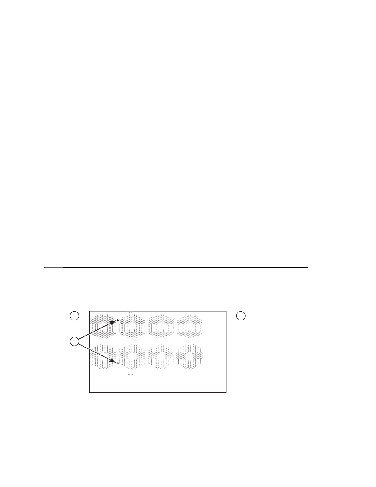
將 PowerConnect B-MLXe 系列機箱安裝在機架上
註
3
1
2
本節說明下列作業:
• 「準備將機箱裝設在機架上」
• 「取下 4 插槽和 8 插槽機箱的運輸螺絲」
• 「8 插槽和 16 插槽機箱搬運指南」
• 「將機箱裝設在機架上」
準備將機箱裝設在機架上
由於 PowerConnect B-MLXe 系列機箱整體重量較重,因此 Dell 建議先將機箱裝在機架上後,再安裝其他模組和
交流電耗材 ( 必要時 )。
在標準 19 吋 (EIA310-D) 機架上可安裝
• 最多十台 PowerConnect B-MLXe 系列的 4 插槽機箱。
• 最多六台 PowerConnect B-MLXe 系列的 8 插槽機箱。
• 最多三台 PowerConnect B-MLXe 系列的 16 插槽機箱。
每台安裝在機架上的 PowerConnect B-MLXe 系列機箱都必須使用四顆 #12-24 的錐形頭螺絲裝設並固定機箱。進
行此作業前,應先將機架組合完畢,並留一把 #2 十字螺絲起子。
取下 4 插槽和 8 插槽機箱的運輸螺絲
PowerConnect B-MLXe 系列 4 插槽和 8 插槽裝置會隨附原本安裝在機箱右側的兩顆螺絲。這兩顆螺絲是用來固
定風扇組,避免再運送途中受損。安裝路由器前必須先取下這兩顆螺絲。第 73 頁的圖 4 顯示螺絲位置。
您必須使用 #2 十字螺絲起子取下螺絲。
圖 4 取下 4 插槽和 8 插槽機箱上的運輸螺絲
1
正面
2
背面
3
運輸螺絲
PowerConnect B-MLXe
53-1001995-01
使用說明指南
73
Page 76
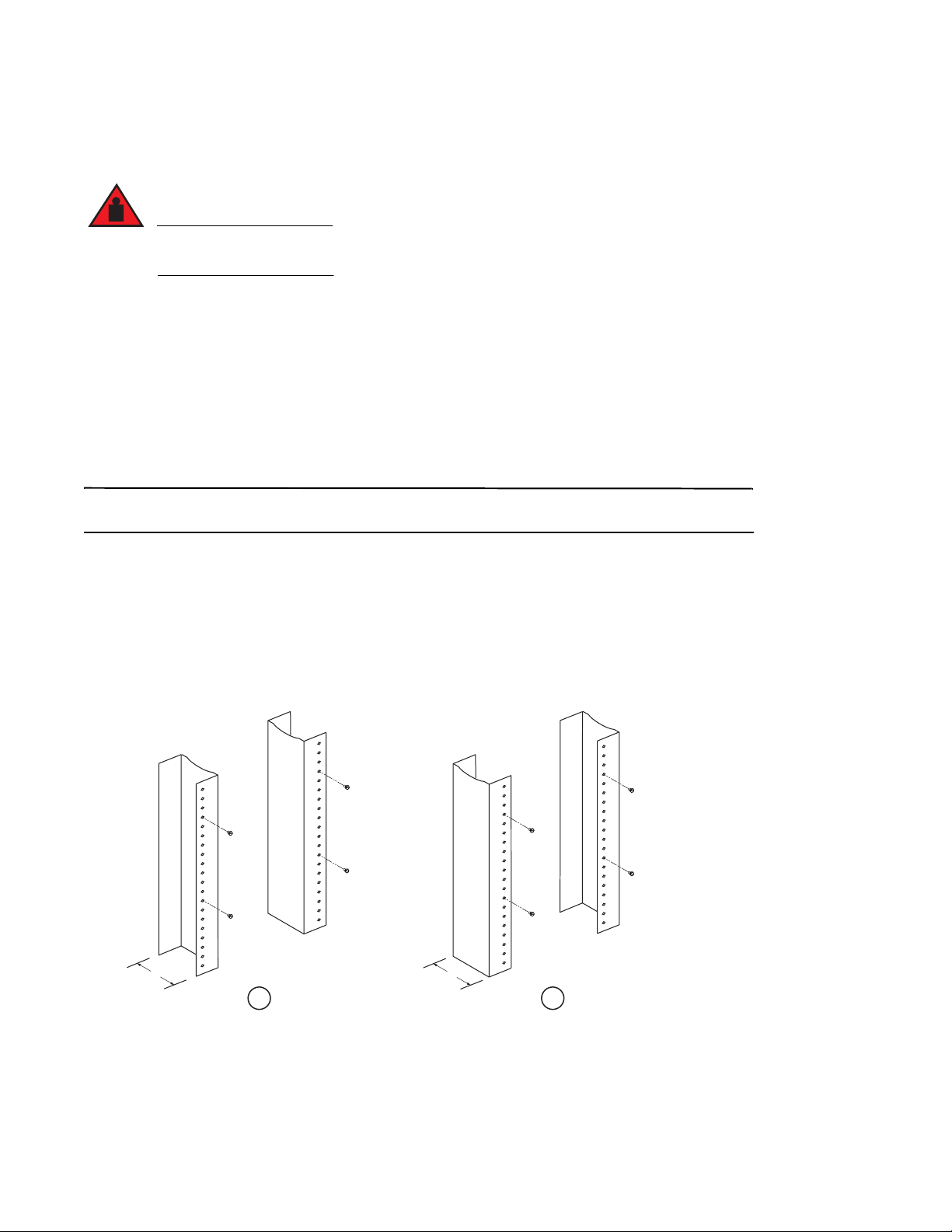
8 插槽和 16 插槽機箱搬運指南
危險
註
完全設置好的 B-MLXe 16 插槽機箱非常重。如需搬運、使用或裝設這些裝置時,請務必兩人同時進
行。
請依照下列指南搬運或移動 8 插槽或 16 插槽機箱:
• 搬運或移動機箱前,請先拔下所有外接連接線。
• 請勿嘗試自行完全設置好的機箱;請務必兩人同時進行。
• 將機箱安裝至機架前,建議先取下機箱元件。
將機箱裝設在機架上
請遵照下列步驟將 PowerConnect B-MLXe 系列機箱裝設在機架上。
您必須使用標準 #12-24 錐形頭螺絲將每個機箱裝設在機架上。請使用十字螺絲起子執行作業。
1. 確定各機箱在機架上的位置。舉例來說,將模組數較少的裝置放在機架上方,模組數較多的裝置至於機架
中央,而模組數完整的裝置則放在機架底部。
2. U 使用機箱裝設托架上的安裝孔槽作為基準,對齊各機架架桿的螺絲,如第 74 頁的圖 5 所示。機架其中一
側螺絲應對齊裝設托架的上方孔洞;而機架另一側的螺絲則需對齊裝設托架的底部孔洞。拴上螺絲後,螺
絲頭背面與機架架桿之間請保留約 1/4 吋的空間。
圖 5 確定機架架桿的螺絲裝設位置
5"
1 2
1
不等邊法蘭設備機架
(Unequal flange equipment rack)
2
3"
網路設備機架
74 PowerConnect B-MLXe
使用說明指南
53-1001995-01
Page 77

3. 首先先從要裝設在機架底部的機箱開始,如圖 6 中的 8 插槽機箱範例所示,將機箱裝到機架上。請至少由
註
危險
1
2
兩個人搬起機箱、將各安裝孔槽較寬的一側滑入機架架桿上的對應裝設螺絲。
圖 6 將 B-MLXe 8 插槽機箱裝到機架上
1
設備機架
4. 將機箱向下滑動,讓螺絲頭位於安裝孔槽較狹窄的一側。
5. 鎖緊螺絲,將機箱固定至定位。若想更加牢固,可額外使用其他螺絲。
若要達到機箱對機架的良好接地效果,可在機箱上裝設星形墊圈。也可在任何單孔接地突耳上使用星形墊
圈,避免接地突耳旋轉。
6. 請重複步驟 2 到步驟 5,將每台機箱裝設至機架上。
2
裝設孔
安裝模組
請依下列步驟將模組安裝到空插槽上。請依照相同程序安裝所有模組。
下列安裝多重模組的順序對於確保妥善安裝十分重要:
• 若是 4 插槽和 8 插槽機箱,請由右至左安裝模組,並從最下排開始逐漸向上安裝。
• 若是 16 插槽機箱,請從路由器左側向右開始插入插槽。
本設備或子組件的內建連接埠僅適合連接內建或未暴露的線路或佈線。本設備或子組件的內建連接
埠不得以金屬方式連接到與外部設備 (OSP) 或其線路連接的介面。這些介面僅作為內建介面使用
( 如 GR-1089-CORE,Issue 4 說明的類型 2 或類型 4 連接埠 ) 且必須獨立於暴露的 OSP 佈線。若要透
過金屬方式將這些介面連接到 OSP 線路,主要防護 (Primary Protector) 效力仍然不足。
PowerConnect B-MLXe
53-1001995-01
使用說明指南
75
Page 78

註
PowerConnect B-MLXe 系列模組屬專用模組,即表示這些模組僅能安裝在 PowerConnect B-MLXe 系列機箱上。舉
警示
警示
警示
危險
例來說,如果您嘗試將 PowerConnect B-MLXe 系列管理模組安裝在其他 Dell 機箱,或者將其他 Dell 機箱專用的
管理模組安裝在 PowerConnect B-MLXe 系列機箱,則該機箱和模組皆無法正常運作。
表 1 提供安裝模組適用的機箱插槽編號。機箱插槽標誌會顯示在插槽底座上。
各 PowerConnect B-MLXe 系列機箱會隨附已安裝的交換核心模組。
表 1 PowerConnect B-MLXe 模組安裝
PowerConnect B-MLXe 系列模組 機箱插槽編號
4 插槽和 8 插槽機箱的管理模組
16 插槽機箱的管理模組
4 插槽機箱的介面模組
8 插槽機箱的介面模組
16 插槽機箱的介面模組
4 插槽和 8 插槽機箱的交換核心模組
16 插槽機箱的交換核心模組
使用電動螺絲起子可能會扭斷螺絲頭,因此不建議使用。
若插槽上未安裝任何模組,請勿取下插槽蓋。若使用未覆蓋的插槽操作機箱,可能會導
致系統過熱。請鎖緊固定插槽蓋的螺絲;如此一來,即便取下鄰近的面板或模組時也不
會掉落。
使用中模組 – M1 ( 左 )
備援模組 – M2 ( 右 )
使用中模組 – M1 ( 上 )
備援模組 – M2 ( 下 )
1 – 4
1 – 8
1 – 16
SF1 – SF3
SF1 – SF4
若您進行模組熱交換,請在拆下模組 ( 或是電源供應器或風扇組 ) 至少兩秒後再將模組插
入同一個插槽。
若打算安裝備援管理模組,請參閱該產品的相關配置指南,了解備援模式運作方式、選用可執行的軟體設定,
以及如何管理備援功能等相關資訊。
將模組安裝至 B-MLXe 系列機箱前,請先備妥下列工具:
• ESD 靜電環,附有可連接到 PowerConnect B-MLXe 系列機箱上 ESD 連接器的插頭。
為了安全起見,ESD 靜電環應附上 1 百萬歐姆的串聯電阻。
• 大型一字螺絲起子。
76 PowerConnect B-MLXe
使用說明指南
53-1001995-01
Page 79

請依照下列步驟將模組安裝至 PowerConnect B-MLXe 系列機箱:
註
1. 若您要安裝模組的空插槽先前未設定過其他模組,請前往步驟 2。若您要安裝模組的插槽先前已設定過其
他模組,請利用本步驟移除舊的設定資訊。
a. 請在配置模式下使用 show running-config 指令,決定插槽的目前配置情形。
PowerConnect(config)# show running-config
目前配置:
!
版本 V5.0.0T163
模組 1 ni-mlx-24-port-1g-copper
!
本範例顯示,插槽 1 目前的配置為 20-port 1 Gbps 銅介面 (copper interface) 模組。
b. 若使用 show running-config 指令輸出來指定模組,請以 no module <slot-number> <module-type> 指令移
除插槽 1 的配置。
PowerConnect(config)# no module 1 ni-mlx-20-port-1g-copper
此指令可移除插槽 1 的配置,讓此插槽準備安裝新的模組。
2. 戴上 ESD 靜電環並將插頭接到機箱上的 ESD 連接器,完成接地。
3. 取出包裝內的模組。
4. 將模組插入插槽內,並沿著卡片導軌推入模組,直到模組兩側的退出鈕旋入模組前端面板。
將模組插入機箱時,請確認該模組的面板和鄰近模組面板不會重疊。
5. 旋轉模組面板的退出開關。此動作可將模組完全置入底板。
6. 放入兩顆螺絲並順時針旋轉,將螺絲固定在模組前端面板上。請使用一字螺絲起子將螺絲拴緊。
7. 輸入 write memory 指令,並確認重新開機後插槽與新模組能否正常運作。
PowerConnect(config)# write memory
寫入 startup-config 已完成。
圖 7 將模組安裝到 4 插槽機箱
PowerConnect B-MLXe
53-1001995-01
使用說明指南
77
Page 80

圖 8 將模組安裝到 8 插槽機箱
圖 9 將模組安裝到 B-MLXe-16 插槽機箱
電源供應器、交換核心及風扇需求
如需有關 PowerConnect B-MLXe 系列裝置上安裝模組的電源供應器、交換核心及風扇需求的詳細資訊,請參閱
硬體安裝指南。
78 PowerConnect B-MLXe
使用說明指南
53-1001995-01
Page 81

安裝電源供應器
危險
警示
警示
表 2 列出 PowerConnect B-MLXe 系列出廠前安裝的電源供應器 ( 交流電或直流電 ) 號碼,以及各裝置可安裝並作
為備援的最大數量。
表 2 B-MLXe 系列的電源供應器
機箱類型 已安裝的電
源供應器
電源供應器
上限
4 插槽
8 插槽
16 插槽
13
24
48
高接觸電流。連接供電器前請先妥善接地。
電源供應器安裝步驟
請遵照下列步驟安裝電源供應器。請使用小型十字或一字螺絲起子執行此作業。
1. 取下電源供應器插槽蓋。
空的電源供應器插槽必須蓋上插槽蓋。
2. 取出包裝內的電源供應器。
3. 利用插槽各邊的導軌將電源供應器插入插槽。請參閱圖 10。
請仔細依循電源供應器插槽各邊的機械導軌,並務必將電源供應器妥善插入導軌內。插入電源供應
器時請留意方向是否正確。
4. 若是 4 插槽機箱,請遵照下列步驟,然後繼續執行步驟 6。
a. 將電源供應器前端面板推入路由器,與底板連接器接合。
b. 將退出調整桿旋轉至電源供應器前端,並固定至定位。
c. 放入兩顆螺絲並順時針旋轉,將螺絲固定在電源供應器前端面板上。請利用一字螺絲起子拴緊螺絲。
PowerConnect B-MLXe
53-1001995-01
使用說明指南
79
Page 82

圖 10 將電源供應器安裝在 4 插槽機箱
1
5. 若是 8 插槽和 16 插槽機箱,請遵照下列步驟,然後繼續執行步驟 6。
a. 沿著卡片導軌將卡片推至定位,然後朝著機箱後方推入電源供應器前端面板。此動作可讓電源供應器連
接器與底板連接器接合。
b. 輕輕將電源供應器前端面板的把手往上提,並朝向電源供應器前端面板推入。此動作可將電源供應器鎖
入定位。
圖 11 將電源供應器安裝在 8 插槽機箱
1
電源供應器
80 PowerConnect B-MLXe
53-1001995-01
使用說明指南
Page 83

圖 12 將電源供應器安裝在 16 插槽機箱
1
2
1
電源供應器
2
釋放閂
6. 如需有關連接電源與路由器的資訊,請參閱第 81 頁的 「連接交流電源」 或第 82 頁的 「連接直流電源」。
7. 如需有關啟動系統的資訊,請參閱第 85 頁的 「啟動電源」。
連接交流電源
交流電源連接步驟
1. 找出 B-MLXe 機箱後置面板上的電源供應器插座。
2. 拉起托線器 (cord retainer) 並將交流電源線接到插座上。
3. 將托線器固定在電源插頭並維持在定位。
PowerConnect B-MLXe
53-1001995-01
使用說明指南
81
Page 84

圖 13 電源線與 B-MLXe 4 插槽機箱交流電源供應器的連接範例
危險
危險
1
3
2
1
接地點
若安裝所需的電源線與機箱隨附的電源線不同,請務必使用標有安全機構 ( 符合當地國家電源
線規範 ) 標誌的電源線。有了此標誌,您就可安心在機箱上使用此電源線。
4. 如需有關啟動系統的資訊,請參閱第 85 頁的 「啟動電源」。
2
電源線
3
托線器
連接直流電源
PowerConnect B-MLXe 系列機箱能以直流電源供電。只要使用直流電對直流電的供電器即可。必須使用 48 V 和
30 A 的直流電;而直流電對直流電的供電器可提供 12 V 和 100 A 的直流電源給機箱使用。
本節說明之程序必須由合格維修人員執行。
請依照下列步驟連接直流電源。
82 PowerConnect B-MLXe
使用說明指南
53-1001995-01
Page 85

1. 使用一字螺絲起子取下鎖住電源供應器突耳上塑膠蓋的兩顆螺絲。
警示
註
1
圖 14 8 插槽與 16 插槽機箱的直流電電源供應器
2
DC IN
DC OUT
ALM
1
1 固定塑膠蓋的螺絲 2 固定電源供應器突耳的螺絲
2. 請使用十字螺絲起子取下各電源供應器突耳。
3. 將 #8 AWG 電源供應器的電線壓接到突耳上,再將突耳接回電源供應器裝置。請請參閱圖 15。
若是安裝與 NEBS 相容的 PowerConnect B-MLXe 系列以及交流電和直流電系統,請使用美國線規
(AWG) 在 6 以上的接地線。接地線的一端必須附有合格廠商的壓接式接頭 ( 機箱隨附 ),而另一端則
是接地端。此接頭必須使用適當工具壓接,才能妥善連接箱內的接地螺絲。將接地線壓接到隨附的
接地突耳前,請務必清潔露出的銅線,並在露出的電線塗上抗氧化劑。
圖 15 將電源供應器的電線壓接到突耳
1
#8 AWG 的電源供應器電線
4. 重新接上在步驟 1 取下的電源供應器突耳塑膠蓋。
5. 將 -48V 纜線接到電源供應器的負極,而 0V 纜線則接到正極。
連接電源供應器時,必須隔絕直流返回 (DC return) 與路由器接地 (DC-I)。
本設備之安裝必須符合 NEC/CEC 法規規範。詳細規範請諮詢地方當局。
PowerConnect B-MLXe
53-1001995-01
使用說明指南
83
Page 86

管理纜線
註
如需 PowerConnect B-MLXe 系列連接的纜線管理相關資訊,請參閱硬體安裝指南。
安裝管理工作站
您可依照下列方式管理 PowerConnect B-MLXe 系列系統:
• 您可以直接將電腦或終端機連接到管理模組的序列 ( 主控台 ) 連接埠。在此介面中可設定附 IP 位址及 Telnet
或 SSH 的 10BaseT/100BaseTX/1000BaseTX 乙太網路 ( 管理 ) 連接埠。此方式可協助您使用 Tel n e t 或 SSH
並經由 10BaseT/100BaseTX/1000BaseTX 乙太網路 ( 管理 ) 連接埠管理裝置。
• 您可以將 PowerConnect B-MLXe 系列機箱連接到現有的管理網路,並透過管理工作站管理機箱和網路裝置。
如需採用此方式,請將機箱連接到管理模組的 10BaseT/100BaseTX/1000BaseTX 乙太網路 ( 管理 ) 連接埠。
現有可連接 10/100 乙太網路連接埠的管理網路必須和使用者封包轉移與路由所使用的網路加以區隔並隔離。
如需有關連接電腦或終端機至管理模組的主控台連接埠或管理連接埠之資訊,請參閱下一節的 「將電腦或終端
機連接到主控台連接埠或乙太網路連接埠」。如需有關連接管理連接埠和網路的資訊,請參閱第 85 頁的 「將
管理模組的乙太網路連接埠連接到網路」。
將電腦或終端機連接到主控台連接埠或乙太網路連接埠
您可利用管理模組的主控台連接埠 ( 配備一個 DB-9 公序列接頭 ) 和 10BaseT/100Base TX 乙太網路連接埠 ( 配備
RJ-45 UTP 接頭 ) 連接電腦和終端機。連接主控台連接埠後,可直接從電腦或終端機存取 PowerConnect B-MLXe
系列機箱 CLI ,或透過 Tel n e t 連線使用電腦或終端機。連接乙太網路連接埠後,可直接從電腦或終端機存取
PowerConnect B-MLXe 系列 CLI 或 Web 管理介面,或透過 Tel n et 連線使用電腦或終端機。
執行本作業前,必須備妥下列項目:
• 執行終端機模擬應用程式或終端機的電腦。
• 若電腦或終端機連接到主控台連接埠時,需準備直通式 EIA/TIA DB-9 序列纜線,其中一端為 DB-9 母接頭,
另一端則是 DB-9 或 DB-25 公╱母接頭,需視電腦或終端機規格而定。您可以向 Dell 訂購序列纜線或自行製
作。若您偏好自行製作,請參閱硬體安裝指南中的針腳配置資訊。
• 若電腦或終端機連接到乙太網路連接埠時,必須採用 5 類 UTP 跳接纜線。如需有關管理連接埠針腳配置的
資訊,請參閱硬體安裝指南。
請依照下列步驟將電腦或終端機連接到主控台連接埠或乙太網路連接埠。
1. 使用合適纜線將電腦或終端機連接到主控台連接埠或乙太網路連接埠。
2. 啟動終端機模擬程式,並將工作階段參數設定為以下內容:
• 傳輸速率:9600 bps
• 資料位元: 8
• 同位元: 無
• 停止位元: 1
• 流量控制:無
84 PowerConnect B-MLXe
53-1001995-01
使用說明指南
Page 87

將管理模組的乙太網路連接埠連接到網路
警示
危險
註
註
管理模組的 10BaseT/100BaseTX/1000BaseTX 乙太網路 ( 管理 ) 連接埠 (RJ-45 UTP 接頭 ) 可讓您將管理連接埠
連接到網路。現有管理網路中的管理工作站便可透過管理應用程式存取 PowerConnect B-MLXe 系列機箱。
若要將管理模組的乙太網路連接埠連接到網路,必須使用 5 類 UTP 直通式纜線 (Dell 不提供 )。將直通式纜線的
一端連接到管理連接埠,另一端則接到網路。
啟動電源
硬體安裝完畢後,即可啟動電源。
1. 請確認所有模組與電源供應器均妥善安裝,且每個模組插槽均附有外蓋。
若插槽上未安裝任何模組,請勿取下插槽蓋。若插槽未加以覆蓋即操作機箱,可能會導致系統過熱。
2. 若使用交流電電源,請將 Dell 隨附的交流電源線其中一端接到交流電源供應器,如第 81 頁的 「連接交流
電源」所示。
將另一端插入 115V 或 120V 的牆壁插座。請重複此步驟連接各個安裝的交流電電源供應器。
若安裝所需的電源線與裝置隨附的電源線不同,請務必使用標有安全機構 ( 符合當地國家電源
線規範 ) 標誌的電源線。有了此標誌,您就可安心在裝置上使用此電源線。
無論插入或取出管理模組和介面模組,PowerConnect B-MLXe 系列機箱的專屬設計均能提供持續不斷電的服
務。因此,系統不會有獨立的開啟╱關閉的電源開關。若要關閉系統,只要拔下電源線即可。
牆壁插座應盡量設置在設備附近,而且必須方便使用。
3. 若提供直流電源供 PowerConnect B-MLXe 系列機箱使用,請依第 82 頁的 「連接直流電源」所述,將電源線
連接到直流電電源供應器。
將纜線另一端連接到直流電源。請重複此步驟連接各個安裝的直流電電源供應器。完成後開啟電源。
4. 確認 PowerConnect B-MLXe 系列機箱是否初始化成功。如需相關資訊,請參閱以下的 「確認運作是否正
常」。
PowerConnect B-MLXe
53-1001995-01
使用說明指南
85
Page 88

確認運作是否正常
PowerConnect# show module
模組 狀態 連接埠啟動 MAC
M1 ( 上 ):NI-MLX-MR Mgmt 模組 使用中
M2 ( 下 ):
F0: NI-MLX-MR 交換核心模組 使用中
S1:
S2:
S3:
S4: NetIron 4 連接埠 10Gig 模組 CARD_STATE_UP 4 000c.db80.0000
S5: NetIron 4 連接埠 10Gig 模組 CARD_STATE_UP 4 000c.db80.0000
S6: NetIron 4 連接埠 10Gig 模組 CARD_STATE_UP 4 000c.db80.0000
S7:
如需確認啟動後 PowerConnect B-MLXe 系列機箱是否運作正常,可執行下列操作:
• 觀察 LED 燈。
• 利用 CLI 顯示模組狀態。
觀察 LED 燈
開啟 PowerConnect B-MLXe 系列機箱電源後可觀察 LED 燈,確認是否初始化成功。有關 LED 燈操作完整說明以
及 CLI show module 指令顯示的狀態訊息等資訊,請參閱硬體安裝指南。
若問題仍未解決,請聯絡技術支援中心。
顯示模組狀態
將電腦或終端機連接到管理模組的主控台或乙太網路連接埠且 PowerConnect B-MLXe 系列機箱初始化成功後,
按下 Enter 即可在終端機模擬視窗中顯示下列 CLI 提示:
PowerConnect>
若看不到此提示,請執行下列動作:
1. 請確認電腦或終端機以及主控台連接埠或乙太網路連接埠的纜線是否接妥。
2. 檢查終端機模擬程式的設定。除了第 84 頁的 「將電腦或終端機連接到主控台連接埠或乙太網路連接埠」
所列的工作階段設定,也請確認終端機模擬工作階段是否在連接主控台連接埠相同的序列連接埠上執行。
若看見此提示 (PowerConnect>) 即表示已連線到系統,並可利用 CLI 顯示模組狀態。請在任一 CLI 層輸入下列指
令:
指定密碼
在預設情況下,PowerConnect B-MLXe 系列 CLI 不受密碼保護。為維護 CLI 存取安全,Dell 強烈建議指定密碼。
CLI 包含下列存取層級:
• 權限 EXEC – 在此層級亦稱為啟用層級,而且可受密碼保護。在此層級中,您可以掌握管理模組快閃記憶體
的檔案,或是管理模組插槽 1 或 2 的 PCMCIA 快閃記憶卡、將系統設定儲存至快閃記憶體,以及清除快取。
• CONFIG – 設定層級。此層級可供您設定系統 IP 位址以及路由功能。若要進入 CONFIG 模式,必須先登入
EXEC 模式的權限層級。
86 PowerConnect B-MLXe
使用說明指南
53-1001995-01
Page 89

您可以設定下列啟用層級的密碼:
註
註
註
• 進階使用者 – 擁有系統讀寫權限。這通常適用於系統管理員,而且是唯一能讓您設定密碼的密碼層級。
設定其他類型的密碼前必須先設定進階使用者密碼。
• 連接埠設定 – 可讀寫特定的連接埠,但無法讀寫通用 ( 全系統 ) 參數。
• 唯讀 – 可存取權限 EXEC 模式和 CONFIG 模式,但僅具備讀取功能。
設定密碼:
1. 在開啟的 CLI 提示下輸入下列指令,即可變更為 EXEC 模式的權限層級:
PowerConnect> enable
PowerConnect#
2. 輸入下列指令存取 CLI 的 CONFIG 層級:
PowerConnect# configure terminal
PowerConnect(config)#
3. 輸入下列指令設定進階使用者密碼:
PowerConnect(config)# enable super-user-password <text>
設定其他類型的密碼前必須先設定進階使用者密碼。
4. 輸入下列指令設定連接埠設定和唯讀密碼:
PowerConnect(config)# enable port-config-password <text>
PowerConnect(config)# enable read-only-password <text>
若忘記進階使用者密碼,請參閱 〈版本資訊〉。
唯讀密碼和連接埠設定密碼必須和進階使用者密碼不同。密碼最多可輸入 48 個字元。
設定 IP 位址
PowerConnect B-MLXe 系列可執行不同資料與控制面板。此架構會影響指定 IP 位址的方式。表 3 說明指定 IP 位
址的介面。
本表中的 「頻內」表示使用者封包進行路由的介面,而 「頻外」則表示傳送系統管理相關控制封包的介面。
表 3 指定 IP 位址
介面 相關實體連接埠 頻外或頻內
管理介面 使用中或備援管理模組中的乙太網路
10/100/1000 連接埠
任何使用者封包進行路由的介面 任何介面模組連接埠 頻內
任何使用者封包進行路由的虛擬介面 任何介面連接埠 頻內
回送介面
–
本節說明下列內容:
頻外
頻內
PowerConnect B-MLXe
53-1001995-01
使用說明指南
87
Page 90

• PowerConnect B-MLXe 系列支援的子網路遮罩
警示
• 如何指定 IP 位址至管理介面
• 如何指定 IP 位址至使用者封包進行路由的介面或虛擬介面
支援子網路遮罩
PowerConnect B-MLXe 系列支援傳統 IP 網路遮罩 (A、B、C 類子網路遮罩等 ) 以及無類別網域間路由選擇 (CIDR)
網路首碼遮罩。
• 若要輸入傳統網路遮罩,請依 IP 位址格式輸入遮罩。例如輸入 「209.157.22.99 255.255.255.0」
作為 C 類子網路遮罩的 IP 位址。
• 若要輸入網路遮罩首碼,請立即在 IP 位址後的遮罩輸入正斜線 (/) 和位元數。例如輸入
「209.157.22.99/24」作為已擁有 24 個明顯 ( 「遮罩」 ) 位元網路遮罩的 IP 位址。
指定 IP 位址至管理介面
為了系統管理方便,您必須指定 IP 位址給使用中的管理模組,而不是指定通用 IP 位址給 B-MLXe。若使用中的
管理模組無法使用且備援模組變成使用中模組,則系統會自動將 IP 位址指定給新的使用中管理模組。
舉例來說,若要指定 IP 位址 10.0.1.1 給管理介面,請執行下列步驟:
1. 在開啟的 CLI 提示下輸入 「enable」:
PowerConnect> enable
2. 在權限 EXEC 層級提示下輸入下列指令 ( 例如 PowerConnect#),然後按下 Enter。此指令會消除原廠測試設
定 ( 若有 ):
PowerConnect# erase startup-config
僅限新系統使用 「erase startup-config」指令。如果在設定過的系統輸入此指令,該指令就會消除原
設定。若不慎消除設定過的系統設定,請輸入寫入記憶體的指令,將執行中的設定儲存到
startup-config 檔案。
3. 輸入下列指令存取 CLI 設定層級:
PowerConnect# configure terminal Privileged EXEC Level
PowerConnect(config)# Global CONFIG Level
4. 輸入下列指令設定管理介面的 IP 位址和遮罩:
PowerConnect(config)# interface management 1
PowerConnect(config-if-mgmt-1)# ip address 10.0.1.1 255.255.255.0
88 PowerConnect B-MLXe
使用說明指南
53-1001995-01
Page 91

指定 IP 位址至介面、虛擬介面或回送介面
警示
您必須指定 IP 位址給使用者封包進行路由的每個介面和虛擬介面;也可以指定 IP 位址給經常用以測試和診斷的
回送介面。您必須透過序列連線方式指定第一個 IP 位址。而後續的位址也可透過 Telnet 或 Web 管理介面使用
CLI。在預設情況下,每個介面、虛擬介面及回送介面最多可設定 24 個 IP 介面。
舉例來說,若要將 IP 位址 192.22.3.44 和子網路遮罩 255.255.255.0 指定給乙太網路介面 1/1,請執行下列步
驟。
1. 在開啟的 CLI 提示下輸入 enable。
PowerConnect> enable
2. 在權限 EXEC 層級提示下輸入下列指令,然後按下 Enter。此指令會消除原廠測試設定 ( 若有 ):
PowerConnect# erase startup-config
輸入此指令後必須重新啟動系統。
僅限新系統使用 「erase startup-config」指令。如果在設定過的系統輸入此指令,該指令就會消除原
設定。若不慎消除設定過的系統設定,請輸入寫入記憶體的指令,將執行中的設定儲存到
startup-config 檔案。
3. 輸入下列指令存取 CLI 設定層級:
PowerConnect# configure terminal
PowerConnect(config)#
4. 輸入下列指令設定乙太網路介面 1/1 的 IP 位址和子網路遮罩:
PowerConnect(config)# interface ethernet 1/1
PowerConnect(config-if-e10000-1/1)# ip address 192.22.3.44 255.255.255.0
如果已經在介面的同一個子網路內設定 IP 位址,請使用次要參數。
啟用和停用介面
在預設情況下,所有 B-MLXe 介面均為停用狀態。若要啟用介面,請在適當的 CLI 介面設定層級中輸入 enable
指令。舉例來說,若要啟用管理介面,請在 CLI 的管理介面設定層級中輸入 enable 指令。
PowerConnect(config-if-mgmt-1)# enable
若要停用各個介面,請在適當的 CLI 介面設定層級中輸入 disable 指令。舉例來說,若要停用管理連接埠,請在
CLI 的管理介面設定層級中輸入 disable 指令。
PowerConnect(config-if-mgmt-1)# disable
PowerConnect B-MLXe
53-1001995-01
使用說明指南
89
Page 92

連接 PowerConnect B-MLXe 系列和網路裝置
您可以將 PowerConnect B-MLXe 系列機箱連接到其他乙太網路裝置。PowerConnect B-MLXe 系列機箱可連接到其
他供應商以及 Dell 的網路裝置。
有關 PowerConnect B-MLXe 系列適用的乙太網路介面模組說明,請參閱硬體安裝指南。這些模組包括 XFP 光
纖、SFP、SFP+ 光纖的介面模組,以及 RJ-45 銅介面。有關這些介面模組支援的 SFP、SFP+ 及 XFP 光纖模組詳
細資料,硬體安裝指南中均有相關說明。
若要連接 PowerConnect B-MLXe 系列機箱和其他網路裝置,請執行下列步驟:
• 必要時請安裝光纖模組
• 視需求使用銅線或光纖纜線連接模組
如需執行上述作業、清潔光纖接頭以及網路連線疑難排解的相關資訊,請參閱硬體安裝指南。
管制通告
關於其他管制資訊,請參閱法規遵循 (Regulatory Compliance) 首頁於 www.dell.com 上的下列位址: www.dell.com/regulatory_compliance。
Información de la NOM (sólo para México)
La información que se proporciona a continuación aparece en el dispositivo descrito en este documento, en cumplimiento de los requisitos de la
Norma Oficial Mexican (NOM):
Importador: Dell Inc. de México, S.A. de C.V.
Paseo de la Reforma 2620-11°Piso
Col. Lomas Altas
11950 México, D.F.
Equipos portátiles
Modelo Voltaje de alimentación Frecuencia Consumo eléctrico
BI-RX-4 100-240CA
50/60Hz
16A
BI-RX-8 100-240CA 50/60Hz 16A
BI-RX-16 100-240CA 50/60Hz 16A
MLXe-4 100-240CA 50/60Hz 16A
MLXe-8 100-240CA 50/60Hz 16A
MLXe-16 100-240CA 50/60Hz 16A
Brocade DCX-4S 100-240CA 50-60Hz 15A
Brocade 8000 100-240CA 47-63Hz 5-2.5A
Informação sobre Órgão Regulador
A marca de certificação se aplica a este Equipamento de Rede de Dados
Para maiores consultas sobre ANATEL visite o site: www.anatel.gov.br
90 PowerConnect B-MLXe
53-1001995-01
使用說明指南
Page 93

53-1001995-01
31 Août 2010
PowerConnect™
Série B-MLXe
Guide de mise en route
53-1001995-01
*53-1001995-01*
Page 94

Remarques, précautions et avertissements
REMARQUE
PRÉCAUTION
AVERTISSEMENT
une REMARQUE indique des informations importantes qui peuvent vous aider à mieux utiliser votre ordinateur.
une PRÉCAUTION indique un risque d'endommagement du matériel ou de perte de données si les
consignes ne sont pas respectées.
un AVERTISSEMENT indique un risque d'endommagement du matériel, de blessure corporelle ou
de mort.
____________________
Les informations que contient ce document sont sujettes à modification sans préavis.
© 2010 Dell Inc. Tous droits réservés. Imprimé aux U.S.A.
La reproduction de ce document, sous quelque forme que ce soit, sans permission écrite de Dell Inc. est strictement interdite.
Marques utilisées dans ce document : Dell, le logo DELL, Inspiron, Dell Precision, Dimension, OptiPlex, Latitude, PowerEdge, PowerVault,
PowerApp, PowerConnect et Dell OpenManage sont des marques de Dell Inc. ; Intel, Pentium et Celeron sont des marques déposées d'Intel
Corporation aux États-Unis et dans d'autres pays ; Microsoft, Windows, Windows Server, MS-DOS et Windows Vista sont des marques ou des
marques déposées de Microsoft Corporation aux États-Unis et/ou dans d'autres pays.
D'autres marques et noms commerciaux peuvent être utilisés dans ce document pour faire référence aux entités se réclamant de ces marques
ou noms ou à leurs produits. Dell Inc. rejette tout intérêt exclusif dans les marques et les noms commerciaux autres que les siens.
Codes de modèles réglementaires : MLXe-4, MLXe-8, MLXe-16
92 Guide de mise en route PowerConnect B-MLXe
53-1001995-01
Page 95

Dans ce guide
•
Présentation . . . . . . . . . . . . . . . . . . . . . . . . . . . . . . . . . . . . . . . . . . . . . . . . . . . . . . . . . . . . . . 93
•
Éléments nécessaires à l'installation . . . . . . . . . . . . . . . . . . . . . . . . . . . . . . . . . . . . . . . . . . 97
•
Planification de site et consignes de sécurité . . . . . . . . . . . . . . . . . . . . . . . . . . . . . . . . . . . 98
•
Déballage du châssis PowerConnect de série B-MLXe . . . . . . . . . . . . . . . . . . . . . . . . . . . 101
•
Consignes de soulèvement des châssis à 4 logements et à 8 logements . . . . . . . . . . . 103
•
Montage d'un châssis dans un rack . . . . . . . . . . . . . . . . . . . . . . . . . . . . . . . . . . . . . . . . . . 103
•
Installation de modules . . . . . . . . . . . . . . . . . . . . . . . . . . . . . . . . . . . . . . . . . . . . . . . . . . . . 105
•
Installation des blocs d'alimentation . . . . . . . . . . . . . . . . . . . . . . . . . . . . . . . . . . . . . . . . . 109
•
Connexion de l'alimentation secteur. . . . . . . . . . . . . . . . . . . . . . . . . . . . . . . . . . . . . . . . . . 112
•
Connexion de l'alimentation en CC . . . . . . . . . . . . . . . . . . . . . . . . . . . . . . . . . . . . . . . . . . . 113
•
Gestion des câbles. . . . . . . . . . . . . . . . . . . . . . . . . . . . . . . . . . . . . . . . . . . . . . . . . . . . . . . .115
•
Connexion d'une station de gestion . . . . . . . . . . . . . . . . . . . . . . . . . . . . . . . . . . . . . . . . . . 115
•
Activation de la source d'alimentation . . . . . . . . . . . . . . . . . . . . . . . . . . . . . . . . . . . . . . . . 116
•
Vérification du bon fonctionnement . . . . . . . . . . . . . . . . . . . . . . . . . . . . . . . . . . . . . . . . . . 117
•
Attribution de mots de passe . . . . . . . . . . . . . . . . . . . . . . . . . . . . . . . . . . . . . . . . . . . . . . . 118
•
Configuration d'adresses IP. . . . . . . . . . . . . . . . . . . . . . . . . . . . . . . . . . . . . . . . . . . . . . . . . 119
•
Connexion du châssis PowerConnect de série B-MLXe à un périphérique réseau . . . . . 122
Présentation
Ce guide fournit des instructions de déballage, d'installation et de configuration d'un châssis PowerConnect B-MLXe
à 4 logements, 8 logements et 16 logements en tant qu'unité autonome. Veuillez remarquer que les documents
supplémentaires suivants sont disponibles :
•
Pour des instructions d'installation et de configuration détaillées, reportez-vous au guide d'installation du
matériel approprié à ce produit.
•
Pour des instructions d'installation spécifiques au rack, reportez-vous aux procédures d'installation de montage
sur un rack appropriées.
Le châssis PowerConnect de série B-MLXe à 4 logements (Figure 46 à la page 94) et le châssis à 8 logements
(Figure 47 à la page 95) peuvent être installés des manières suivantes :
•
Comme unités autonomes sur une surface plate.
•
Dans une armoire de 19 pouces Electronic Industries Association (EIA310-D). Les unités de série B-MLXe
comportent des supports de montage intégrés pour l'installation en rack.
•
Dans un rack de montage central de télécommunications (Telco). Pour monter centralement l'unité
PowerConnect dans le rack, commandez séparément un kit de montage central auprès de votre fournisseur
PowerConnect. Ce kit contient deux supports de montage en L et des instructions d'installation des supports et
de montage de l'unité.
Guide de mise en route PowerConnect B-MLXe 93
53-1001995-01
Page 96

Le châssis PowerConnect de série B-MLXe à 16 logements (Figure 48 à la page 96) peut être installé des
7
6
5
1324
8910
manières suivantes :
•
Dans une armoire de 19 pouces Electronic Industries Association (EIA310-D). Les unités de série B-MLXe
comportent des supports de montage intégrés pour l'installation en rack.
•
Dans un rack à montage central de télécommunications (Telco). Pour monter centralement l'unité
PowerConnect dans le rack, commandez séparément un kit de montage central auprès de votre fournisseur
PowerConnect. Ce kit contient deux supports de montage en L et des instructions d'installation des supports et
de montage de l'unité.
Ce guide répertorie les étapes de configuration de base requises pour la configuration du châssis PowerConnect
de série B-MLXe. Vous trouverez des informations de configuration supplémentaires dans le guide d'installation
du matériel.
La Figure 46 illustre le châssis PowerConnect de série B-MLXe à 4 logements et l'emplacement des composants.
FIGURE 46
1 Logement d'interface 2 4 Connecteur ESD 7 Logement d'interface 3 10 Logement d'interface 4
2 Logement de matrice de
commutation 2
3 Logement de matrice de
commutation 3
Châssis PowerConnect B-MLXe à 4 logements
5 Logement d'interface 1 8 Logement de gestion 1
6 Logement de matrice de
commutation 1
9 Logement de gestion 2
94 Guide de mise en route PowerConnect B-MLXe
53-1001995-01
Page 97

La Figure 47 illustre le châssis PowerConnect de série B-MLXe à 8 logements et l'emplacement des composants.
8
10
12
6
9
7
5
4
3
14 15
11
16 17
1 2
13
18
FIGURE 47
Châssis PowerConnect B-MLXe à 8 logements
1 Logement d'interface 1 6 Logement de matrice de
commutation 2
2 Logement d'interface 2 7 Logement de matrice de
commutation 3
3 Logement d'interface 3 8 Logement d'interface 5 13 Logement de gestion 2 18 Connecteur ESD
4 Logement d'interface 4 9 Logement d'interface 6 14 Logement de bloc
5 Logement de matrice de
commutation 1
10 Logement d'interface 7 15 Logement de bloc
11 Logement d'interface 8 16 Logement de bloc
d'alimentation 3
12 Logement de gestion 1 17 Logement de bloc
d'alimentation 4
d'alimentation 1
d'alimentation 2
Guide de mise en route PowerConnect B-MLXe 95
53-1001995-01
Page 98

La Figure 48 illustre le châssis PowerConnect de série B-MLXe à 16 logements et l'emplacement des composants.
12
13
14
15
16
17
18
19
20
21
22
23
1
2
3
4
5
6
7
8
91011
FIGURE 48
PowerConnect B-MLXe châssis à 16 logements
1-16 Logements d'interface 1 à 16 20 Logement de matrice de commutation 4
17 Logement de matrice de commutation 1 21 Logement de gestion 1
18 Logement de matrice de commutation 2 22 Logement de gestion 2
19 Logement de matrice de commutation 3 23 Connecteur ESD
96 Guide de mise en route PowerConnect B-MLXe
53-1001995-01
Page 99

Éléments nécessaires à l'installation
REMARQUE
Ce document décrit la procédure d'installation des châssis PowerConnect de série B-MLXe à 4, 8 et 16 logements et le
montage de ces châssis dans des racks d'équipement de 19 pouces à l'aide des supports intégrés à chaque châssis.
Pour monter centralement le châssis dans un rack, commandez le kit à montage central auprès de votre fournisseur
PowerConnect. Des instructions d'installation sont fournies avec le kit de rack. Cette section décrit les éléments livrés
avec le châssis PowerConnect de série B-MLXe et les éléments dont vous aurez besoin pour l'installation.
Éléments livrés avec les unités
Les éléments suivants sont livrés :
•
Le châssis à 4 logements est livré avec les composants suivants installés :
-
Deux modules de matrice de commutation large bande.
-
Un cache de logement dans chaque logement de module vide. Le cache de logement couvre un logement
dans lequel aucun module ne doit actuellement être installé, ce qui assure une ventilation appropriée.
-
Un ensemble de plateau de ventilateur, qui se trouve dans le côté avant droit du routeur. Pour en savoir plus
sur les ventilateurs, voir le guide d'installation du matériel.
-
Un bloc d'alimentation (Secteur ou CC).
•
Le châssis à 8 logements est livré avec les composants suivants installés :
-
Deux modules de matrice de commutation large bande.
-
Un cache de logement dans chaque logement de module vide. Le cache de logement couvre un logement
dans lequel aucun module ne doit actuellement être installé, ce qui assure une ventilation appropriée.
-
Un ensemble de plateau de ventilateur, qui se trouve dans le côté avant droit du routeur. Pour en savoir plus
sur les ventilateurs, voir le guide d'installation du matériel.
-
Deux blocs d'alimentation (secteur ou CC).
•
Le châssis à 16 logements est livré avec les composants suivants installés :
-
Trois modules de matrice de commutation large bande.
-
Un cache de logement dans chaque logement de module vide. Le cache de logement couvre un logement
dans lequel aucun module ne doit actuellement être installé, ce qui assure une ventilation appropriée.
-
Un ensemble de plateau de ventilateur, qui se trouve dans le côté avant droit du châssis et deux ensembles
de ventilateur qui se trouvent à l'arrière du châssis. Pour en savoir plus sur les ventilateurs, voir le guide
d'installation du matériel.
-
Quatre blocs d'alimentation (secteur ou CC).
•
La carte de garantie.
•
Un câble d'alimentation secteur 115 V pour chaque bloc d'alimentation secteur que vous achetez auprès
de Dell.
•
Une carte de redirection Web contenant des images de logiciel et la documentation utilisateur (notamment
ce guide).
s'il manque des éléments, contactez le lieu d'achat.
Guide de mise en route PowerConnect B-MLXe 97
53-1001995-01
Page 100

Éléments que vous devez fournir
REMARQUE
•
Rack d'équipement d'armoire de 19 pouces Electronic Industries Association (EIA310-D) assemblé.
•
Vis à tête cylindrique no. 12 à 24 standard pour le montage du châssis sur les racks d'équipement.
•
Tournevis cruciforme no. 2.
•
Tournevis à lame plate large.
•
Kit de rack de montage central (en option). Commandez-le de votre fournisseur PowerConnect.
•
Un bracelet ESD avec une prise pour connexion au connecteur ESD sur le châssis.
Planification de site et consignes de sécurité
Les étapes et précautions de sécurité suivantes assurent une installation et un fonctionnement corrects.
Planification de site
Effectuez les étapes suivantes pour vous assurer que votre site est prêt pour l'installation.
Infrastructure de câblage
Vérifiez que le câblage correct est installé sur le site. Pour des informations concernant le câblage, voir le guide
d'installation du matériel.
Emplacement de l'installation
Avant d'installer le châssis, planifiez son emplacement et son orientation par rapport aux autres appareils et
équipements. À des fins de refroidissement, laissez au moins 15,24 cm (6 pouces) d'espace entre les côtés, l'avant,
et l'arrière du châssis et les murs ou autres obstructions. Si un châssis est installé dans un boîtier perforé, les
ouvertures des perforations doivent couvrir au moins 60 pour cent de la surface.
Le châssis PowerConnect de série B-MLXe peut être installé dans une infrastructure de Télécommunications
réseau et là où s'appliquent les conditions NEC. De plus, il peut être installé dans un CBN (Common Bonding
Network - Réseau de masse commun) ou dans un IBN (Isolated Bonding Network - Réseau de masse isolé).
Il n'est pas conçu pour des installations OSP (Outside Plant - Réseau extérieur).
Consignes de sécurité
Avant de poursuivre l'installation, lisez les mises en garde et avertissements concernant le châssis PowerConnect
de série B-MLXe.
98 Guide de mise en route PowerConnect B-MLXe
53-1001995-01
 Loading...