

Page 1

53-1002111-01
02 November 2010
PowerConnect B-MLXe
Hardware Installation Guide
Page 2

Information in this document is subject to change without notice.
© 2010 Dell Inc. All rights reserved.
Reproduction of these materials in any manner whatsoever without the written permission of Dell Inc. is strictly forbidden.
Trademarks used in this text: Dell, the DELL logo, Inspiron, Dell Precision, Dimension, OptiPlex, Latitude, PowerEdge, PowerVault,
PowerApp, Dell OpenManage and the YOURS IS HERE logo are trademarks of Dell Inc.; Intel, Pentium, and Celeron are registered
trademarks of Intel Corporation in the U.S. and other countries; Microsoft, Windows, Windows Server, MS-DOS and Windows Vista
are either trademarks or registered trademarks of Microsoft Corporation in the United States and/or other countries.
Other trademarks and trade names may be used in this document to refer to either the entities claiming the marks and names or
their products.
Dell Inc. disclaims any proprietary interest in trademarks and trade names other than its own.
Regulatory Model Codes: Brocade MLXe-4, Brocade MLXe-8, Brocade MLXe-16
Page 3

Contents
About This Document
Audience . . . . . . . . . . . . . . . . . . . . . . . . . . . . . . . . . . . . . . . . . . . . . . . . ix
How this document is organized . . . . . . . . . . . . . . . . . . . . . . . . . . . . .ix
Supported hardware . . . . . . . . . . . . . . . . . . . . . . . . . . . . . . . . . . . . . . . x
What’s new in this document. . . . . . . . . . . . . . . . . . . . . . . . . . . . . . . . x
Document conventions. . . . . . . . . . . . . . . . . . . . . . . . . . . . . . . . . . . . . x
Text formatting . . . . . . . . . . . . . . . . . . . . . . . . . . . . . . . . . . . . . . . . x
Command syntax conventions . . . . . . . . . . . . . . . . . . . . . . . . . . . x
Command examples . . . . . . . . . . . . . . . . . . . . . . . . . . . . . . . . . . .xi
Notes, cautions, and danger notices . . . . . . . . . . . . . . . . . . . . . .xi
Notice to the reader . . . . . . . . . . . . . . . . . . . . . . . . . . . . . . . . . . . . . . . xi
Getting technical help or reporting errors . . . . . . . . . . . . . . . . . . . . . xii
Contacting Dell. . . . . . . . . . . . . . . . . . . . . . . . . . . . . . . . . . . . . . . xii
Chapter 1 Product Overview
Dell router overview . . . . . . . . . . . . . . . . . . . . . . . . . . . . . . . . . . . . . . . 1
Router applications. . . . . . . . . . . . . . . . . . . . . . . . . . . . . . . . . . . . . . . . 1
Hardware features . . . . . . . . . . . . . . . . . . . . . . . . . . . . . . . . . . . . . . . . 1
PowerConnect B-MLXe routers . . . . . . . . . . . . . . . . . . . . . . . . . . . 1
Router modules. . . . . . . . . . . . . . . . . . . . . . . . . . . . . . . . . . . . . . . . . . . 6
Management modules . . . . . . . . . . . . . . . . . . . . . . . . . . . . . . . . . 6
Interface modules . . . . . . . . . . . . . . . . . . . . . . . . . . . . . . . . . . . . . 8
Switch fabric modules . . . . . . . . . . . . . . . . . . . . . . . . . . . . . . . . .15
High-speed switch fabric modules . . . . . . . . . . . . . . . . . . . . . . . 17
Power supplies. . . . . . . . . . . . . . . . . . . . . . . . . . . . . . . . . . . . . . . 17
Rack mounting brackets . . . . . . . . . . . . . . . . . . . . . . . . . . . . . . .18
Cooling system for PowerConnect B-MLXe routers . . . . . . . . . .18
NIBI-16-FAN-EXH-A high-speed fan assemblies. . . . . . . . . . . . .20
Rack mount kit. . . . . . . . . . . . . . . . . . . . . . . . . . . . . . . . . . . . . . .21
Supported software features . . . . . . . . . . . . . . . . . . . . . . . . . . . . . . . 21
Chapter 2 Installing a PowerConnect B-MLXe Core Router
Installation precautions . . . . . . . . . . . . . . . . . . . . . . . . . . . . . . . . . . .23
General precautions . . . . . . . . . . . . . . . . . . . . . . . . . . . . . . . . . .23
Power precautions . . . . . . . . . . . . . . . . . . . . . . . . . . . . . . . . . . . .24
PowerConnect B-MLXe Hardware Installation Guide iii
53-1002111-01
Page 4

Installing a PowerConnect B-MLXe-4 router . . . . . . . . . . . . . . . . . . .25
Preparing the installation site. . . . . . . . . . . . . . . . . . . . . . . . . . . 26
Unpacking a PowerConnect B-MLXe-4 router . . . . . . . . . . . . . .26
Installing a PowerConnect B-MLXe-4 router in a rack or cabinet26
Installing PowerConnect B-MLXe-4 modules . . . . . . . . . . . . . . .34
Installing power supplies in a PowerConnect B-MLXe-4 router.38
Connecting AC power . . . . . . . . . . . . . . . . . . . . . . . . . . . . . . . . . .39
Final steps . . . . . . . . . . . . . . . . . . . . . . . . . . . . . . . . . . . . . . . . . .40
Installing a PowerConnect B-MLXe-8 router . . . . . . . . . . . . . . . . . . .40
Preparing the installation site. . . . . . . . . . . . . . . . . . . . . . . . . . . 40
Unpacking a PowerConnect B-MLXe-8 router . . . . . . . . . . . . . .40
Installing a PowerConnect B-MLXe-8 router in a rack . . . . . . . . 41
Mounting your device in a cabinet . . . . . . . . . . . . . . . . . . . . . . .43
Installing PowerConnect B-MLXe-8 modules . . . . . . . . . . . . . . .48
Installing power supplies in the PowerConnect B-MLXe-8 router51
Connecting AC power . . . . . . . . . . . . . . . . . . . . . . . . . . . . . . . . . .52
Final steps . . . . . . . . . . . . . . . . . . . . . . . . . . . . . . . . . . . . . . . . . .53
Installing a PowerConnect B-MLXe-16 router . . . . . . . . . . . . . . . . . .53
Preparing the installation site. . . . . . . . . . . . . . . . . . . . . . . . . . . 53
Unpacking a PowerConnect B-MLXe-16 router . . . . . . . . . . . . .54
Installing a PowerConnect B-MLXe-16 router in a rack. . . . . . .54
Installing modules in a PowerConnect B-MLXe 16-slot router .62
Installing power supplies in a PowerConnect B-MLXe-16 router66
Final steps . . . . . . . . . . . . . . . . . . . . . . . . . . . . . . . . . . . . . . . . . .68
Attaching a management station. . . . . . . . . . . . . . . . . . . . . . . . . . . . 68
Attaching a PC or terminal to the console
port or Ethernet port . . . . . . . . . . . . . . . . . . . . . . . . . . . . . . . . . .68
Activating the power source . . . . . . . . . . . . . . . . . . . . . . . . . . . . . . . .69
Verifying proper operation . . . . . . . . . . . . . . . . . . . . . . . . . . . . . . . . .70
Observing the LEDs . . . . . . . . . . . . . . . . . . . . . . . . . . . . . . . . . . .70
Displaying the module status . . . . . . . . . . . . . . . . . . . . . . . . . . .72
Chapter 3 Using the Dell Structured Cabling Components
Cable cinch overview . . . . . . . . . . . . . . . . . . . . . . . . . . . . . . . . . . . . .75
MRJ21 procedures . . . . . . . . . . . . . . . . . . . . . . . . . . . . . . . . . . . . . . . 76
Cable cinch with two mRJ21 cables . . . . . . . . . . . . . . . . . . . . . . 76
Cable cinch with three mRJ21 cables . . . . . . . . . . . . . . . . . . . .77
Cable cinch with four mRJ21 cables. . . . . . . . . . . . . . . . . . . . . . 78
Cable cinch with five mRJ21 cables . . . . . . . . . . . . . . . . . . . . . .79
Cable cinch with six mRJ21 cables. . . . . . . . . . . . . . . . . . . . . . .80
Cable cinch with seven mRJ21 cables . . . . . . . . . . . . . . . . . . . . 81
Cable cinch with eight mRJ21 cables. . . . . . . . . . . . . . . . . . . . .82
iv PowerConnect B-MLXe Hardware Installation Guide
53-1002111-01
Page 5

RJ45 procedures. . . . . . . . . . . . . . . . . . . . . . . . . . . . . . . . . . . . . . . . .83
Cable cinch with one group of RJ45 cables . . . . . . . . . . . . . . . .83
Cable cinch with two groups of RJ45 cables . . . . . . . . . . . . . . .84
Cable cinch with three groups of RJ45 cables. . . . . . . . . . . . . .85
Cable cinch with four groups of RJ45 cables. . . . . . . . . . . . . . .86
Cable cinch with five groups of RJ45 cables . . . . . . . . . . . . . . .87
Cable cinch with six groups of RJ45 cables . . . . . . . . . . . . . . . .88
Cable cinch with seven groups of RJ45 cables . . . . . . . . . . . . .89
Cable cinch with eight groups of RJ45 cables . . . . . . . . . . . . . .90
Chapter 4 Connecting a Router to a Network Device
Assigning permanent passwords . . . . . . . . . . . . . . . . . . . . . . . . . . . . 91
Configuring IP addresses . . . . . . . . . . . . . . . . . . . . . . . . . . . . . . . . . .92
Support of subnet masks . . . . . . . . . . . . . . . . . . . . . . . . . . . . . .92
Assigning an IP address to a management interface . . . . . . . .93
Assigning IP addresses to an interface, virtual interface,
or loopback interface. . . . . . . . . . . . . . . . . . . . . . . . . . . . . . . . . .94
Enabling and disabling the interfaces . . . . . . . . . . . . . . . . . . . .95
Understanding management port functions . . . . . . . . . . . . . . . . . . .95
Connecting the router to a network device . . . . . . . . . . . . . . . . . . .95
Installing a fiber-optic transceiver. . . . . . . . . . . . . . . . . . . . . . . .96
Cabling a fiber-optic transceiver . . . . . . . . . . . . . . . . . . . . . . . . .96
Cleaning fiber-optic ports and connectors . . . . . . . . . . . . . . . . .96
Troubleshooting network connections . . . . . . . . . . . . . . . . . . . .97
Testing network connectivity . . . . . . . . . . . . . . . . . . . . . . . . . . . . . . . 97
Pinging an IP address . . . . . . . . . . . . . . . . . . . . . . . . . . . . . . . . . 97
Tracing a route . . . . . . . . . . . . . . . . . . . . . . . . . . . . . . . . . . . . . . .98
Chapter 5 Managing Routers and Modules
Managing the device. . . . . . . . . . . . . . . . . . . . . . . . . . . . . . . . . . . . . .99
Disabling and re-enabling power to interface modules. . . . . . .99
Monitoring I2C failures on management modules . . . . . . . . .100
Displaying device status and temperature readings . . . . . . . .102
Displaying the Syslog configuration and static
and dynamic buffers . . . . . . . . . . . . . . . . . . . . . . . . . . . . . . . . .104
Managing switch fabric modules . . . . . . . . . . . . . . . . . . . . . . . . . . .106
Forcing HSF modules to operate in normal mode . . . . . . . . . .106
Managing the cooling system. . . . . . . . . . . . . . . . . . . . . . . . . . . . . .107
Configuring the cooling system. . . . . . . . . . . . . . . . . . . . . . . . .107
Manually setting the fan speed . . . . . . . . . . . . . . . . . . . . . . . .111
Monitoring the cooling system . . . . . . . . . . . . . . . . . . . . . . . . .111
Temperature log reduction . . . . . . . . . . . . . . . . . . . . . . . . . . . .112
Managing interface modules . . . . . . . . . . . . . . . . . . . . . . . . . . . . . .113
Configuring interface module boot parameters. . . . . . . . . . . .113
Changing priority of slots for interface modules . . . . . . . . . . .118
Disabling and re-enabling power to
interface modules . . . . . . . . . . . . . . . . . . . . . . . . . . . . . . . . . . .119
PowerConnect B-MLXe Hardware Installation Guide v
53-1002111-01
Page 6

Enabling and disabling management module
CPU usage calculations . . . . . . . . . . . . . . . . . . . . . . . . . . . . . . . . . .120
Displaying CPU usage . . . . . . . . . . . . . . . . . . . . . . . . . . . . . . . .120
Displaying management module CPU usage . . . . . . . . . . . . . . . . .122
Removing MAC address entries . . . . . . . . . . . . . . . . . . . . . . . . . . . .123
Chapter 6 Upgrading Software Images and Configuration Files
Upgrading Software Images and Configuration Files . . . . . . . . . . .125
Important software upgrade considerations. . . . . . . . . . . . . . . . . .126
General upgrade considerations . . . . . . . . . . . . . . . . . . . . . . .127
Special upgrade information for PowerConnect B-MLXe routers127
Interface module software upgrade considerations . . . . . . . .127
Important memory requirement information. . . . . . . . . . . . . .128
CLI upgrade commands for R05.1.00 . . . . . . . . . . . . . . . . . . . . . . .130
Software upgrade procedures . . . . . . . . . . . . . . . . . . . . . . . . . . . . .130
Determining current software image versions. . . . . . . . . . . . .131
Upgrading the combined IronWare Application Image on
management modules . . . . . . . . . . . . . . . . . . . . . . . . . . . . . . .131
Upgrading the monitor image on a management module . . .131
Upgrading the boot image on a management module . . . . . .132
Upgrading the boot and monitor images on interface modules132
Upgrading interface modules using the combined FPGA image133
Additional upgrade steps . . . . . . . . . . . . . . . . . . . . . . . . . . . . . . . . .134
Upgrading MBRIDGE images on management modules . . . .134
Upgrading individual FPGA images on interface modules . . .135
Rebooting the management module. . . . . . . . . . . . . . . . . . . . . . . .136
Performing a Hitless OS upgrade. . . . . . . . . . . . . . . . . . . . . . . . . . .137
Performing an image coherence check. . . . . . . . . . . . . . . . . . . . . .137
Performing a coherence check without a reload. . . . . . . . . . .138
Displaying image versions . . . . . . . . . . . . . . . . . . . . . . . . . . . . . . . .138
Using the show flash command . . . . . . . . . . . . . . . . . . . . . . . .138
Configurations conditions specific to NI-MLX-1Gx48-T modules. .145
Loading and saving configuration files . . . . . . . . . . . . . . . . . . . . . .146
Configuring file size for startup and running configuration . .146
Configuration buffers. . . . . . . . . . . . . . . . . . . . . . . . . . . . . . . . .147
Replacing the startup configuration with
the running configuration . . . . . . . . . . . . . . . . . . . . . . . . . . . . .148
Replacing the startup configuration
with the running configuration . . . . . . . . . . . . . . . . . . . . . . . . .148
Retaining the current startup configuration . . . . . . . . . . . . . .148
Copying a configuration file to or from a TFTP server . . . . . . .149
Making local copies of the startup configuration file . . . . . . .149
Hitless OS upgrade . . . . . . . . . . . . . . . . . . . . . . . . . . . . . . . . . . . . . .150
vi PowerConnect B-MLXe Hardware Installation Guide
53-1002111-01
Page 7

Dynamic configuration loading. . . . . . . . . . . . . . . . . . . . . . . . . . . . .152
Loading configuration information into
the running-config file . . . . . . . . . . . . . . . . . . . . . . . . . . . . . . . .154
Using SNMP to save and load configuration
information . . . . . . . . . . . . . . . . . . . . . . . . . . . . . . . . . . . . . . . . . . . .154
Erasing image and configuration files . . . . . . . . . . . . . . . . . . . . . . .155
File synchronization . . . . . . . . . . . . . . . . . . . . . . . . . . . . . . . . . . . . .155
File synchronization between active and
standby management modules . . . . . . . . . . . . . . . . . . . . . . . .155
File synchronization between management
and interface modules . . . . . . . . . . . . . . . . . . . . . . . . . . . . . . .156
Scheduling a system reload . . . . . . . . . . . . . . . . . . . . . . . . . . . . . . .157
Reloading at a specific time . . . . . . . . . . . . . . . . . . . . . . . . . . .158
Reloading after a specific amount of time . . . . . . . . . . . . . . . .158
Displaying the amount of time before a
scheduled reload . . . . . . . . . . . . . . . . . . . . . . . . . . . . . . . . . . . .158
Canceling a scheduled reload. . . . . . . . . . . . . . . . . . . . . . . . . .158
Diagnostic error codes and remedies for
TFTP transfers . . . . . . . . . . . . . . . . . . . . . . . . . . . . . . . . . . . . . . . . . .158
Chapter 7 Router Maintenance
Hardware maintenance schedule . . . . . . . . . . . . . . . . . . . . . . . . . .161
Replacing a management module. . . . . . . . . . . . . . . . . . . . . . . . . .161
Replacing an interface module . . . . . . . . . . . . . . . . . . . . . . . . . . . .161
Removing and replacing an interface module . . . . . . . . . . . . .162
Replacing a switch fabric module . . . . . . . . . . . . . . . . . . . . . . . . . .162
Replacing a fiber-optic transceiver . . . . . . . . . . . . . . . . . . . . . . . . .162
Cabling a fiber-optic transceiver . . . . . . . . . . . . . . . . . . . . . . . .163
Replacing a power supply. . . . . . . . . . . . . . . . . . . . . . . . . . . . . . . . .163
Determining which power supply failed . . . . . . . . . . . . . . . . . .163
Setting the threshold for power supply monitoring . . . . . . . . .164
Clearing power supply failure timestamps. . . . . . . . . . . . . . . .164
Displaying power supply monitoring timestamps . . . . . . . . . .165
Enabling a power supply shutdown . . . . . . . . . . . . . . . . . . . . .165
Powering on the power supply through the CLI . . . . . . . . . . . .165
Replacing a power supply . . . . . . . . . . . . . . . . . . . . . . . . . . . . .166
Replacing fan assemblies. . . . . . . . . . . . . . . . . . . . . . . . . . . . . . . . .167
Replacing fan assemblies in a 16-slot router . . . . . . . . . . . . .167
Replacing the fan tray assembly in 4-slot and 8-slot routers .170
Replacing the air filters . . . . . . . . . . . . . . . . . . . . . . . . . . . . . . .172
PowerConnect B-MLXe Hardware Installation Guide vii
53-1002111-01
Page 8

Chapter 8 Hardware Specifications
Hardware specifications for PowerConnect B-MLXe routers . . . . .175
Power specifications . . . . . . . . . . . . . . . . . . . . . . . . . . . . . . . . .175
Physical dimensions for PowerConnect B-MLXe routers. . . . .177
Operating environment specifications for PowerConnect B-MLXe
routers . . . . . . . . . . . . . . . . . . . . . . . . . . . . . . . . . . . . . . . . . . . .177
Storage environment specifications for PowerConnect B-MLXe
routers . . . . . . . . . . . . . . . . . . . . . . . . . . . . . . . . . . . . . . . . . . . .177
Safety agency approvals . . . . . . . . . . . . . . . . . . . . . . . . . . . . . .177
Electromagnetic approvals . . . . . . . . . . . . . . . . . . . . . . . . . . . . 177
Port specifications for all router models . . . . . . . . . . . . . . . . . . . . .178
Console port pin assignments . . . . . . . . . . . . . . . . . . . . . . . . .178
Management port pin assignments . . . . . . . . . . . . . . . . . . . . .179
Power cords. . . . . . . . . . . . . . . . . . . . . . . . . . . . . . . . . . . . . . . . . . . .179
Appendix A Regulatory Statements
U.S.A. . . . . . . . . . . . . . . . . . . . . . . . . . . . . . . . . . . . . . . . . . . . . . . . . .183
Industry Canada statement . . . . . . . . . . . . . . . . . . . . . . . . . . . . . . .183
Europe and Australia. . . . . . . . . . . . . . . . . . . . . . . . . . . . . . . . . . . . .183
Germany. . . . . . . . . . . . . . . . . . . . . . . . . . . . . . . . . . . . . . . . . . . . . . .183
Japan . . . . . . . . . . . . . . . . . . . . . . . . . . . . . . . . . . . . . . . . . . . . . . . . .184
Power cords (Japan Denan) . . . . . . . . . . . . . . . . . . . . . . . . . . . . . . .184
China . . . . . . . . . . . . . . . . . . . . . . . . . . . . . . . . . . . . . . . . . . . . . . . . .185
Korea . . . . . . . . . . . . . . . . . . . . . . . . . . . . . . . . . . . . . . . . . . . . . . . . .185
Russia . . . . . . . . . . . . . . . . . . . . . . . . . . . . . . . . . . . . . . . . . . . . . . . .185
Appendix B Caution and Danger Notices
Cautions. . . . . . . . . . . . . . . . . . . . . . . . . . . . . . . . . . . . . . . . . . . . . . .187
Dangers . . . . . . . . . . . . . . . . . . . . . . . . . . . . . . . . . . . . . . . . . . . . . . .194
viii PowerConnect B-MLXe Hardware Installation Guide
53-1002111-01
Page 9

About This Document
Audience
This document is designed for system administrators with a working knowledge of Layer 2 and
Layer 3 switching and routing.
If you are using a Dell device, you should be familiar with the following protocols if applicable to
your network – IP, RIP, OSPF, BGP, ISIS, IGMP, PIM, MPLS, and VRRP.
How this document is organized
This document is organized to help you find the information that you want as quickly and easily as
possible.
The document contains the following components:
• Chapter 1, “Product Overview” - Provides an overview of PowerConnect B-MLXe.
• Chapter 2, “Installing a PowerConnect B-MLXe Core Router” - Provides installation instructions
for PowerConnect B-MLXe routers.
• Chapter 3, “Using the Dell Structured Cabling Components” - Provides information on how to
use the cabling components with PowerConnect B-MLXe routers.
• Chapter 4, “Connecting a Router to a Network Device” - Describes how to connect
PowerConnect B-MLXe routers to network devices.
• Chapter 5, “Managing Routers and Modules” - Provides information on management tasks for
PowerConnect B-MLXe routers.
• Chapter 6, “Upgrading Software Images and Configuration Files” - Provides instructions on how
to upgrade software for PowerConnect B-MLXe routers.
• Chapter 7, “Router Maintenance” - Describes maintenance procedures for PowerConnect
B-MLXe routers.
• Chapter 8, “Hardware Specifications”- Provides hardware specifications for PowerConnect
B-MLXe routers.
• Appendix A, “Regulatory Statements” - Contains regulatory information for PowerConnect
B-MLXe routers.
• Appendix B, “Caution and Danger Notices” - Contains Caution and Danger notices in four
languages for PowerConnect B-MLXe routers.
PowerConnect B-MLXe Hardware Installation Guide ix
53-1002111-01
Page 10

Document conventions
Supported hardware
In instances in which procedures or parts of procedures documented here apply to some devices
but not to others, this guide identifies exactly which devices are supported and which are not.
Although many different hardware configurations are tested and supported by Dell, documenting
all possible configurations and scenarios is beyond the scope of this document.
The following hardware platforms are described in this document:
• PowerConnect B-MLXe-4 router
• PowerConnect B-MLXe-8 router
• PowerConnect B-MLXe-16 router
What’s new in this document
The following information has been added to this hardware installation guide for this release:
• PowerConnect B-MLXe-4 router information
• PowerConnect B-MLXe-8 router information
• PowerConnect B-MLXe-16 router information
Document conventions
This section describes text formatting conventions and important notice formats used in this
document.
Text formatting
The narrative-text formatting conventions that are used are as follows:
bold text Identifies command names
italic text Provides emphasis
code text Identifies CLI output
Command syntax conventions
.
Command syntax in this manual follows these conventions:
Identifies the names of user-manipulated GUI elements
Identifies keywords
Identifies text to enter at the GUI or CLI
Identifies variables
Identifies document titles
x PowerConnect B-MLXe Hardware Installation Guide
53-1002111-01
Page 11
Document conventions
NOTE
CAUTION
DANGER
command and
parameters
[ ] Optional parameter.
<variable> Variables are printed in italics enclosed in angled brackets < >.
... Repeat the previous element, for example “member [;member...]”
| Choose from one of the parameters.
Commands and parameters are printed in bold.
Command examples
This document describes how to perform simple upgrade and configuration tasks using the
command line interface (CLI), but does not describe the commands in detail. For complete
descriptions of commands for PowerConnect B-MLXe routers, see the Brocade NetIron
Configuration Guide.
Notes, cautions, and danger notices
The following notices and danger statements are used in this manual. They are listed below in
order of increasing severity of potential hazards.
A note provides a tip, guidance, or advice, emphasizes important information, or provides a
reference to related information.
A Caution statement alerts you to situations that can be potentially hazardous to you or cause
damage to hardware, firmware, software, or data.
A Danger statement indicates conditions or situations that can be potentially lethal or extremely
hazardous to you. Safety labels are also attached directly to products to warn of these conditions
or situations.
Notice to the reader
This document may contain references to the trademarks of the following corporations. These
trademarks are the properties of their respective companies and corporations.
These references are made for informational purposes only.
Corporation Referenced trademarks and products
Phillips Screw Company, Inc. Phillips
PowerConnect B-MLXe Hardware Installation Guide xi
53-1002111-01
Page 12

Document conventions
NOTE
Getting technical help or reporting errors
Dell Technical Support is committed to ensuring that your investment in our products remains
cost-effective. If you need assistance or find errors in the manuals, contact Dell Technical Support.
When contacting Dell technical Support have the device configuration file and an output capture of
show tech-support command available.
Contacting Dell
For customers in the United States, call 800-WWW.DELL (800.999.3355).
If you do not have an active Internet connection, you can find contact information on your purchase
invoice, packing slip, bill, or Dell product catalog.
Dell provides several online and telephone-based support and service options. Availability varies by
country and product, and some services may not be available in your area. To contact Dell for sales,
technical support, or customer service issues:
1. Visit http://www.support.dell.com.
2. Click your country or region at the bottom of the page. For a full listing of countries and regions,
click All.
3. In the Support menu, click All Support.
4. Choose the method of contacting Dell that is convenient for you.
xii PowerConnect B-MLXe Hardware Installation Guide
53-1002111-01
Page 13

Chapter
Product Overview
Dell router overview
Dell routers provide high-performance routing to service providers, metro topologies, and Internet
Exchange Points, offering the following benefits:
• 10 Gbps Ethernet ports that process both inbound and outbound user packets
• IPv4 routing with a very large hardware-based forwarding table and powerful hardware-based
Access Control List (ACL) and rate limiting functions
• IPv6 routing including hardware-based forwarding and dual-stack support
• High availability (redundancy) of the following hot-swappable critical router components:
- Management modules
- Fans
- Power supplies
- Switch fabric modules
• A management (10BaseT or 100BaseTX or 1000BaseTX Ethernet) port for connectivity to your
existing management network
• Increased Ternary Content Addressable Memory (TCAM) on the interface modules to process
routing protocols
• Increased processor Random Access Memory (RAM) on management and interface modules
supports larger default Media Access Control (MAC) address tables and the IP route tables
1
Router applications
Dell routers are commonly deployed in the following situations:
• Layer 2 metro networks
• Multiprotocol Label Switching (MPLS) Layer 3 Virtual Private Network (VPN) service provider
networks supporting multi-VRFs and RFC 2547bis
• MPLS Layer 2 VPN service provider networks supporting both Virtual Private LAN Service
(VPLS) and Virtual Leased Line (VLL)
Hardware features
This section describes the major hardware components of Dell routers.
PowerConnect B-MLXe routers
PowerConnect B-MLXe routers are available in the following models:
PowerConnect B-MLXe Hardware Installation Guide 1
53-1002111-01
Page 14
Hardware features
7
6
5
2
1
4
8 9
10
3
1
• PowerConnect B-MLXe-4: 4 interface slots
• PowerConnect B-MLXe-8: 8 interface slots
• PowerConnect B-MLXe-16: 16 interface slots
Figure 1, Figure 2, and Figure 3 illustrate these models.
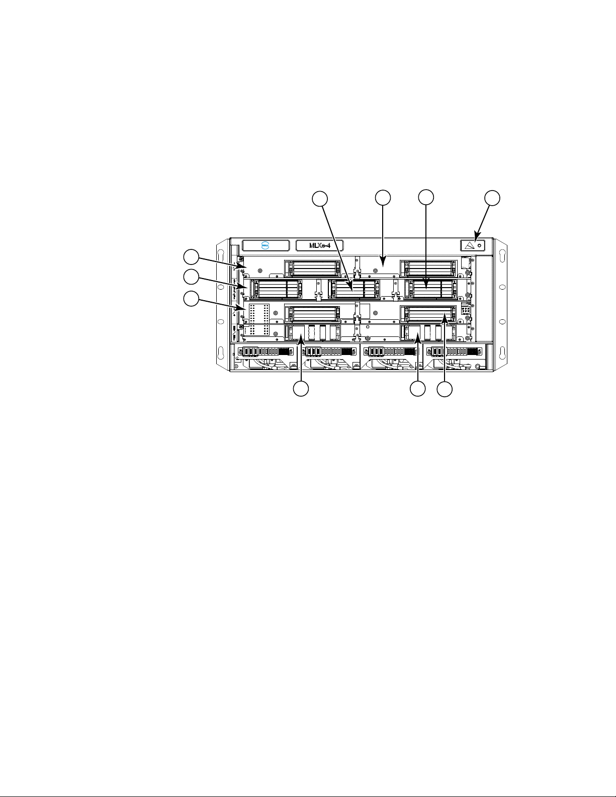
FIGURE 1 PowerConnect B-MLXe-4 router
1 Interface slot 2 4 ESD connector 7 Interface slot 3 10 Interface slot 4
2 Switch fabric slot 2 5 Interface slot 1 8 Management slot 1
3 Switch fabric slot 3 6 Switch fabric slot 1 9 Management slot 2
2 PowerConnect B-MLXe Hardware Installation Guide
53-1002111-01
Page 15
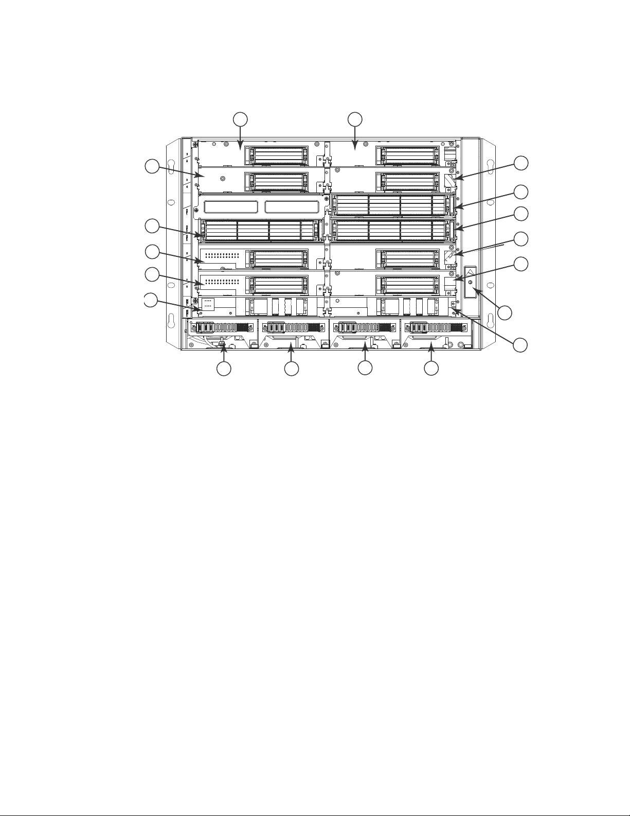
FIGURE 2 PowerConnect B-MLXe-8 router
8
10
12
6
9
7
5
4
3
14 15
11
16
17
1 2
13
18
Hardware features
1
1 Interface slot 1 6 Switch fabric slot 2 11 Interface slot 8 16 Power supply slot 3
2 interface slot 2 7 Switch fabric slot 3 12 Management slot 1 17 Power supply slot 4
3 Interface slot 3 8 Interface slot 5 13 Management slot 2 18 ESD connector
4 Interface slot 4 9 Interface slot 6 14 Power supply slot 1
5 Switch fabric slot 1 10 Interface slot 7 15 Power supply slot 2
PowerConnect B-MLXe Hardware Installation Guide 3
53-1002111-01
Page 16
Hardware features
12
13
14
15
16
17
18
19
20
21
22
23
1
2
3
4
5
6
7
8
91011
1
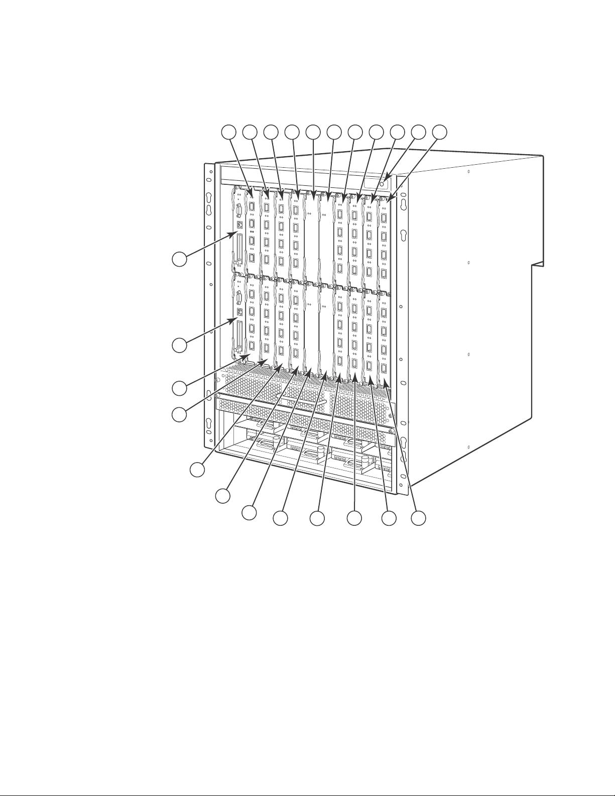
FIGURE 3 PowerConnect B-MLXe-16 router
1-16 Interface slots 1-16 20 Switch fabric slot 4
17 Switch fabric slot 1 21 Management slot 1
18 Switch fabric slot 2 22 Management slot 2
19 Switch fabric slot 3 23 ESD connector
PowerConnect B-MLXe-4 router components
The following components are factory-installed in the PowerConnect B-MLXe-4 routers:
• Two high-speed switch fabric modules.
• A slot blank in each empty module slot. The slot blank covers a slot that does not currently
have a module installed in it, ensuring proper airflow.
4 PowerConnect B-MLXe Hardware Installation Guide
53-1002111-01
Page 17

Hardware features
1
• A fan tray assembly, which is located in the front right side of the router. For more information
about fans, refer to “Cooling system for PowerConnect B-MLXe routers” on page 18.
• One power supply.
You can install the following components in the router slots:
• Up to two management modules (one active and one redundant).
• Up to three switch fabric modules.
• Up to four interface modules.
• Up to three power supplies (AC).
PowerConnect B-MLXe-8 router components
The following components are factory-installed in the PowerConnect B-MLXe-8 routers:
• Two high-speed switch fabric modules.
• A slot blank in each empty module slot. The slot blank covers a slot that does not currently
have a module installed in it, ensuring proper airflow.
• A fan tray assembly, which is located in the front right side of the router. For more information
about fans, refer to “Cooling system for PowerConnect B-MLXe routers” on page 18.
• Two power supplies.
You can install the following components in the router slots:
• Up to two management modules (one active and one redundant).
• Up to three switch fabric modules.
• Up to eight interface modules.
• Up to four power supplies (AC).
PowerConnect B-MLXe-16 router components
The following components are factory-installed in PowerConnect B-MLXe-16 routers:
• Three high-speed switch fabric modules.
• A slot blank in each empty module slot. The slot blank covers a slot that does not currently
have a module installed in it, ensuring proper airflow.
• A fan tray assembly located in the front right side of the router, and two fan assemblies located
at the rear of the router. For more information about fans, refer to “Cooling system for
PowerConnect B-MLXe routers” on page 18.
• Four power supplies.
You can install the following components in the router slots:
• Up to two management modules (one active and one redundant).
• Up to four switch fabric modules.
• Up to 16 interface modules.
• Up to eight power supplies (AC).
PowerConnect B-MLXe Hardware Installation Guide 5
53-1002111-01
Page 18
Router modules
Pwr
Active
10/100/1000
Port 1
Port 2
Console
RX-BI-MR
1
Router modules
The following sections describe management modules, interface modules, and switch fabric
modules.
The figures in the previous sections show the router slots where you install modules and power
supplies. For installation instructions for these components, refer to the appropriate installation
chapter in this guide for your model.
Management modules
Tab le 1 lists the management modules that are available for PowerConnect B-MLXe routers.
TABLE 1 Management modules
Part number Description
NI-MLX-MR PowerConnect B-MLXe management module, 1 GB SDRAM, dual PCMCIA slots, EIA or
The management module controls the hardware components, runs the networking protocols, and
provides the Real Time Operating System (RTOS).
TIA-232 and 10/100/1000 Ethernet ports for out-of-band management.
Each router requires one management module, and can accommodate a second module for
redundancy. A redundant management module works in conjunction with the active management
module. If the active module becomes unavailable, the redundant management module
automatically takes over the system operation, minimizing system downtime. For information about
the redundancy feature, refer to the “Using a Redundant Management Module” chapter in the
PowerConnect B-MLXe Configuration Guide.
Management modules are installed in dedicated slots marked M1 and M2. By default, the module
installed in slot M1 is the active management module.
Management modules are hot-swappable, which means you can remove and replace them without
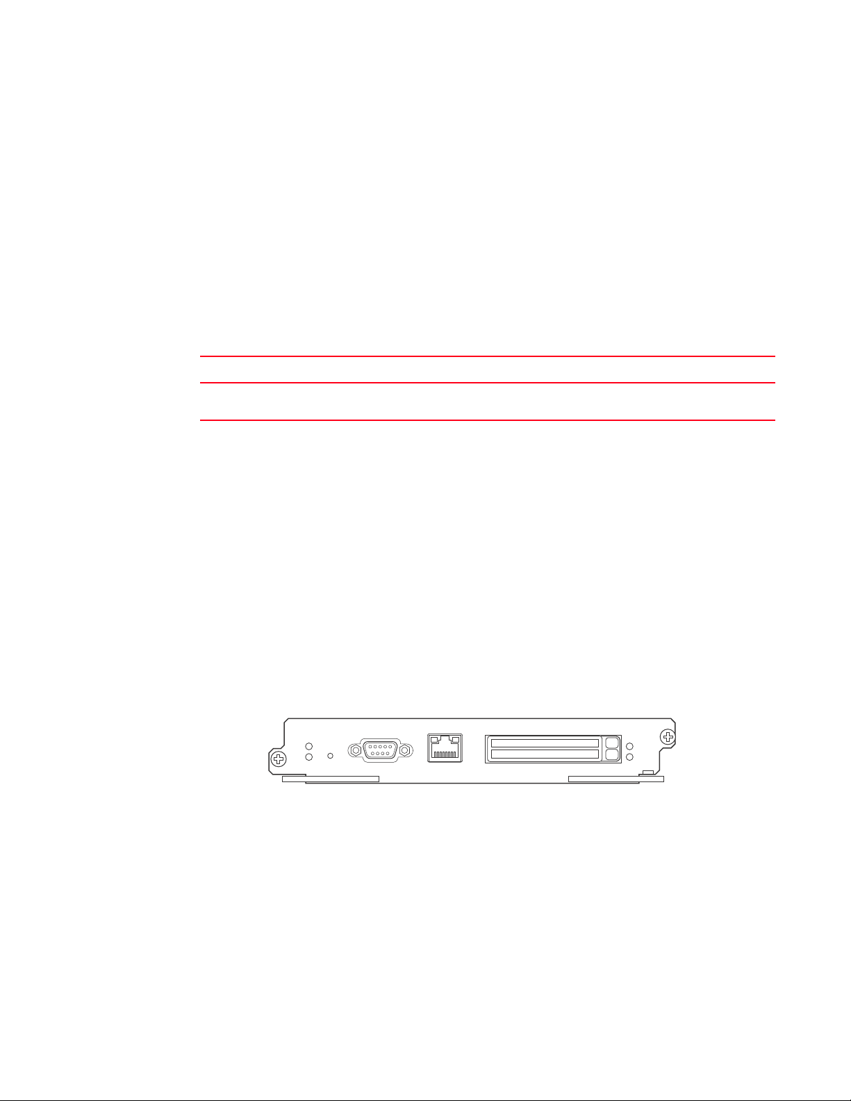
powering down the system. Figure 4 shows the management module front panel.
FIGURE 4 Management module front panel
The front panel contains the following control features:
• Two PCMCIA slots
• A console port
• A 10/100/1000 Ethernet port
• Six LEDs
6 PowerConnect B-MLXe Hardware Installation Guide
53-1002111-01
Page 19

Router modules
NOTE
NOTE
1
PCMCIA slots
PCMCIA slots support flash PC cards. A flash PC card provides storage space in addition to system
flash memory. You can store boot images, startup configuration files, running configuration files,
and other system files on the flash PC card. This allows you to perform system management tasks,
such as copying files between flash PC cards, or copying files between a flash PC card and flash
memory.
Console port
The console port is a standard DB-9 serial connector through which you can attach a PC or terminal
to configure the router using the CLI.
The console port interfaces the control plane only. It does not interface the data plane.
10/100/1000 Ethernet port
The management module also contains a 10BaseT, 100BaseTX, or 1000BaseTX auto-sensing,
auto-negotiating Ethernet port. This port has an RJ45 unshielded twisted pair (UTP) connector.
Typical uses of this port include but are not limited to the following:
• Connecting a PC to configure, monitor, and manage the system through a Telnet or SSHv2
connection.
• Connecting to the 10BaseT, 100BaseTX, or 1000BaseTX port for connectivity to your existing
management network. You can then access the router and configure, monitor, and manage the
system from a management station.
The existing management network into which you can connect the 10/100/1000 Ethernet port
must be separate and isolated from the network over which user packets are switched and routed.
For information about the functionality of the management port, refer to “Understanding
management port functions” on page 95.
For information about connecting a PC to the 10/100/1000 Ethernet port, refer to “Attaching a
management station” on page 205.
Unlike the 10 Gbps Ethernet ports, the out-of-band port does not interface the LAN. Instead, the
out-of-band port can interface with a separate system management network, and allows you to do
the following tasks:
• Access the router through Telnet, the Web management interface, or the SNMP Network
Manager software.
• Access a TFTP server to perform system upgrade tasks.
• Access SNMP messages or protocol data units (PDUs).
• Send Syslog packets.
• Access the system through RADIUS AAA.
Management module LEDs
Tab le 2 describes the LEDs on the management module.
PowerConnect B-MLXe Hardware Installation Guide 7
53-1002111-01
Page 20

Router modules
1
TABLE 2 Management module LEDs
LED Position State Meaning
Port 1
and
Port 2
Active Lower Left On The module is functioning as the active management module.
Pwr Upper Left On The module is receiving power.
10/100/1000
Ethernet Port
10/100/1000
Ethernet Port
Each adjacent to
the PCMCIA slot
that it represents
Above and right of
RJ45 connector
Above and left of
RJ45 connector
On or blinking The software is currently accessing the PCMCIA flash card.
Off The software is not currently accessing a PCMCIA flash card, although there is
one inserted in the slot.
Off The module is functioning as the redundant management module.
Off The module is not receiving power.
On (Green) A link is established with the remote port.
Off No link is established with the remote port.
On or blinking
(Yellow)
Off for an
extended period
The port is transmitting and receiving packets.
The port is not transmitting or receiving packets.
Interface modules
Tab le 3 lists the interface modules that are available for PowerConnect B-MLXe routers.
TABLE 3 Interface modules
Part Number Description
DL-MLX-10Gx4-X-ML 4-port 10 Gbps Ethernet module with IPv4, IPv6, and MPLS hardware support--requires
XFP optics
DL-MLX-1GFx24-X-ML 24-port FE or GE (100/1000) module with IPv4, IPv6, and MPLS hardware
support--requires SFP optics
DL-MLX-1GCx24-X-ML 24-port 10/100/1000 copper modules with IPv4, IPv6, and MPLS hardware support
DL-NI-MLX-10Gx8-M
DL-NI-MLX-10Gx8-D
Depending on your router model, you can install up to 16 interface modules.
Interface modules are hot-swappable, which means you can remove and replace them without
powering down the system.
10 Gbps Ethernet interface modules (4-port)
Figure 5 shows 4-port 10 Gbps Ethernet interface module front panels.
8 PowerConnect B-MLXe Hardware Installation Guide
53-1002111-01
Page 21
Router modules
Lnk
Active
Lnk
Active
Lnk
Active
Lnk
Active
1
2
34
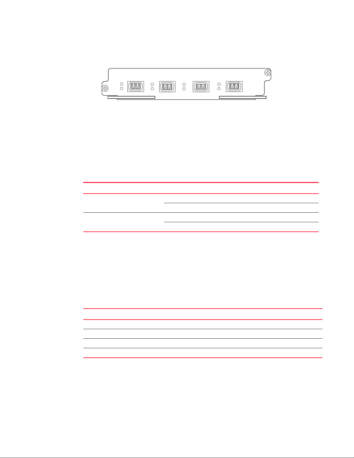
FIGURE 5 4-port 10 Gbps Ethernet module front panels
The front panel of the 4-port module includes the following features:
• Four LEDs per port
• Four 10 Gbps Ethernet XFP optics ports
10 Gbps Ethernet interface module LEDs
All 4-port interface modules have LEDs that indicate the status of each port, as described in
Tab le 4.
TABLE 4 10 Gbps Ethernet module LEDs
LED Location State Meaning
1
Link Left of each
Ethernet port
Active Left of each
Ethernet port
On A link is established with the remote port.
Off A link is not established with the remote port.
On The port is transmitting and receiving packets.
Off The port is not transmitting or receiving packets.
10 Gbps Ethernet ports
The 10 Gbps Ethernet module has four physical ports that allow you to connect your router to other
network routers at a speed of 10 Gbps.
You must insert XFP-compliant fiber-optic transceivers (provided by Dell) in each port you intend to
use. XFP-compliant transceivers provide an optical or physical medium-dependent (PMD) interface
for single- or multi-mode fiber that can be used with the LAN physical layer (PHY).
Tab le 5 lists the 10 Gbps XFP-compliant fiber-optic transceivers that are available from Dell.
TABLE 5 XFP-compliant transceivers for 10 Gbps Ethernet interface modules
Part number Description
10G-XFP-SR 850 nm serial pluggable XFP optic (LC), target range 300m over multi-mode fiber.
10G-XFP-LR 1310 nm serial pluggable XFP optic (LC) for up to 10km over single-mode fiber.
10G-XFP-ER 1550 nm serial pluggable XFP optic (LC) for up to 40km over single-mode fiber.
10G-XFP-CX4 10-Base-CX4, XFP transceiver, 5 km, CX connector.
For more information about fiber-optic transceivers and associated cabling, refer to “Installing a
fiber-optic transceiver” on page 96.
PowerConnect B-MLXe Hardware Installation Guide 9
53-1002111-01
Page 22
Router modules
NOTE
NOTE
1
2
7
8
1
8-port 10 Gbps interface modules
For PowerConnect B-MLXe routers, the 8-port, 10 Gbps interface modules (NI-MLX-10Gx8-M and
NI-MLX-10Gx8-D) provide eight 10 Gbps ports that support SFP+ optics. These modules contain an
internal flash memory of 16 MB for local storage of CPU images, and 32 MB for local storage of
FPGA images. Each 8-port 10 Gbps Ethernet interface module can support a buffer of 256 MB.
When installing NI-MLX-10Gx8-M or NI-MLX-10Gx8-D modules, you must first upgrade the software
on all interface modules and management modules to Multi-Service IronWare software 5.1 or later.
For more information on upgrading the software, refer to Chapter 6, “Upgrading Software Images
and Configuration Files”.
NI-MLX-10Gx8-D interface modules do not support MPLS.
Routers that are loaded with one or more NI-MLX-10Gx8-M or NI-MLX-10Gx8-D modules must also
have high-speed switch fabric modules installed in order to operate. You can replace switch fabric
modules while the system is powered on and running.
For PowerConnect B-MLXe routers, NI-MLX-10Gx8-M and NI-MLX-10Gx8-D modules require the
installation of high-speed switch fabric modules and high-speed fans. For more information about
high-speed switch fabric modules, see “High-speed switch fabric modules” on page 17. For
information about the high-speed fans, see “NIBI-16-FAN-EXH-A high-speed fan assemblies” on
page 20.
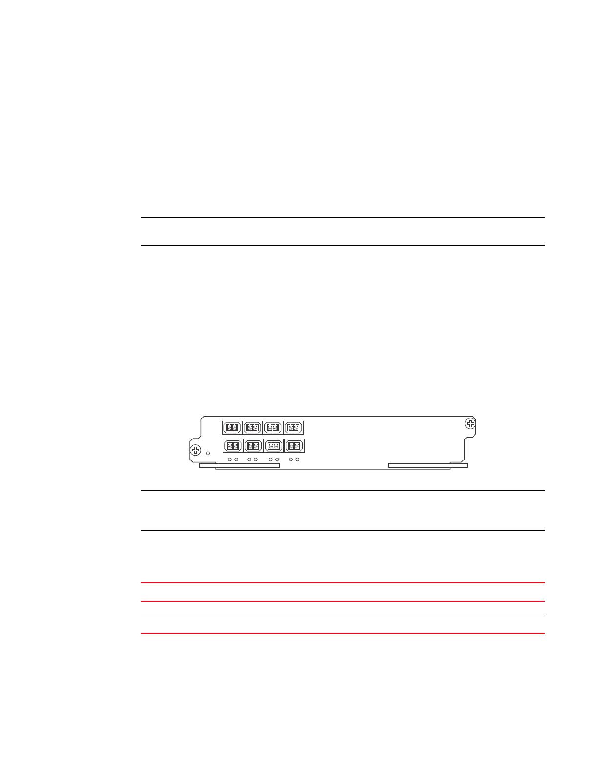
Figure 6 illustrates the faceplate of the NI-MLX-10Gx8-M and NI-MLX-10Gx8-D modules.
FIGURE 6 NI-MLX-10Gx8-M and NI-MLX-10Gx8-D module faceplate
NI-MLX-10Gx8-M and NI-MLX-10Gx8-D modules are designed for use with PowerConnect B-MLXe
routers only.
NI-MLX-10Gx8-M and NI-MLX-10Gx8-D modules support the SFP+ optics listed in Tabl e 6. These
modules do not support SFP optics.
TABLE 6 SFP+ optic transceivers for NI-MLX-10Gx8-M and NI-MLX-10Gx8-D Ethernet interface modules
Part number Description
10G-SFPP-SR 10GBASE-SR serial pluggable SFP+ optic (LC), target range 300 m over multi-mode fiber
10G-SFPP-LR 10GBASE-LR serial pluggable SFP+ optic (LC) for up to 10 km over single-mode fiber
NI-MLX-10Gx8-M and NI-MLX-10Gx8-D interface module LEDs
The NI-MLX-10Gx8-M and NI-MLX-10Gx8-D Ethernet interface module LEDs indicate module and
port status, as described in Table 7 .
10 PowerConnect B-MLXe Hardware Installation Guide
53-1002111-01
Page 23

NOTE
TABLE 7 NI-MLX-10Gx8-M and NI-MLX-10Gx8-D Ethernet module LEDs
LED Location State Meaning
Router modules
1
Power Lower left corner of
module
Link/Activity Underneath the
ports. Top port LED
on left, bottom port
LED on right.
Green Module is receiving power
Off Module is not receiving power
Green
blinking
Off Port is disabled.
Port enabled and link is up.
Power supply requirements for NI-MLX-10Gx8-M and NI-MLX-10Gx8-D modules
When installing NI-MLX-10Gx8-M or NI-MLX-10Gx8-D modules, consider the following power supply
requirements for each type of router:
• 4-slot routers
You can install up to three NI-MLX-10Gx8-M or NI-MLX-10Gx8-D modules using a single 1200W
power supply. You can achieve a 1+1 power redundancy by installing four additional power
supplies.
If four NI-MLX-10Gx8-M or NI-MLX-10Gx8-D modules are installed, you will need a minimum of
two power supplies. You can achieve 2+2 power redundancy by installing two additional power
supplies.
• 8-slot routers
In MLXe-8 routers, you can install up to six NI-MLX-10Gx8-M or NI-MLX-10Gx8-D modules using
two 1200W power supplies. You can achieve a 2+2 power redundancy by installing two
additional power supplies.
For MLXe-8 routers, if you install seven or more NI-MLX-10Gx8-M or NI-MLX-10Gx8-D modules,
you will need a minimum of three power supplies. You can achieve 3+1 power redundancy by
installing one additional power supply.
For MLX 8-slot routers, you can install up to eight NI-MLX-10Gx8-M or NI-MLX-10Gx8-D
modules using two 1200W power supplies. You can achieve 2+2 power redundancy by
installing two additional power supplies
• 16-slot routers
You can install up to 16 NI-MLX-10Gx8-M or NI-MLX-10Gx8-D modules using four 1200W
power supplies. You can achieve a 4+4 power redundancy by installing four additional power
supplies.
If you install thirteen or more NI-MLX-10Gx8-M or NI-MLX-10Gx8-D modules, you will need a
minimum of five power supplies. You can achieve 5+3 power redundancy by installing three
additional power supplies.
When installing NI-MLX-10Gx8-M or NI-MLX-10Gx8-D modules, you must upgrade the software
on all interface modules and management modules to the appropriate software release. For
more information on the appropriate software release refer to the Release Notes. For more
information about upgrading the software, refer to Chapter 6, “Upgrading Software Images and
Configuration Files”.
NI-MLX-10Gx8-D modules do not support Multiprotocol Label Switching (MPLS).
PowerConnect B-MLXe Hardware Installation Guide 11
53-1002111-01
Page 24
Router modules
1
If you try to configure MPLS on device that has NI MLX 8x10G -D modules installed, you will see
the following error message.
PowerConnect MLX-8 Router(config)# router mpls
The command can't be used when system contains -d class modules.
If you install an NI-MLX-10Gx8-D module in a device that is running MPLS, the NI-MLX-10Gx8-D
module will boot in INTERACTIVE mode, and the following error message is displayed.
R2-MLX#
Module is inserted into slot 7
SYSLOG: May 28 16:22:35:<13>May 28 16:22:35 System: Module was inserted to
slot 7
Module 7 is -d class, it can't work when router mpls is enabled.
Reset slot 7
SYSLOG: May 28 16:22:48 :<13>May 28 16:22:48 Module 7 is reset by mgmt
(reason: boot to interactive mode)
24-port 100/1000 Ethernet interface module
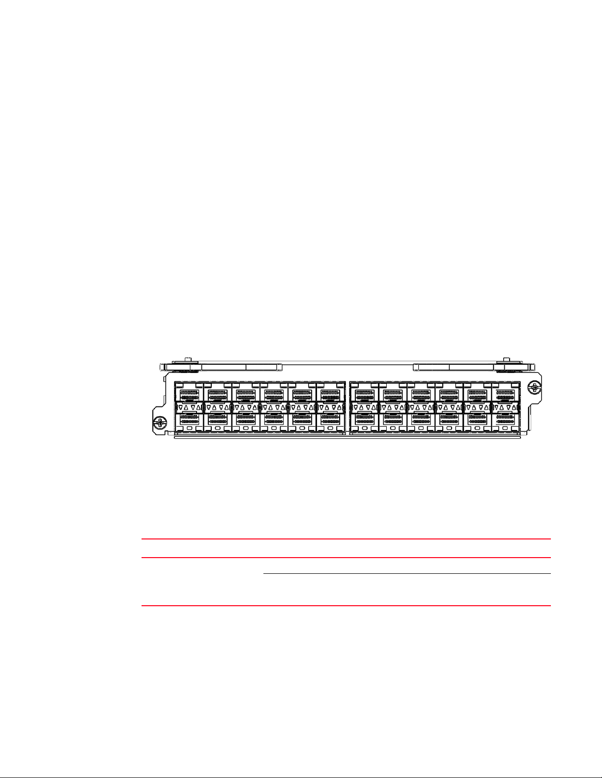
Figure 7 shows the front panel of the 24-port 100/1000 Gbps Ethernet SFP interface module.
FIGURE 7 24-port 100/1000 Ethernet module front panel
The front panel includes the following features:
• LEDs to the left support the top ports, LEDs to the right support the bottom ports
• 24 100/1000 Ethernet SFP ports
Tab le 8 describes the LEDs for the 24-port 100/1000 Ethernet module
TABLE 8 24-port 100/1000 Ethernet module LEDs
Position State Meaning
Below each Ethernet port.
(Left-side LED supports port in
top row. Right-side LED supports
port in bottom row.)
100/1000 Ethernet ports
The 100/1000 Ethernet interface module contains 24 physical ports, through which you can
connect your router to other network routers at a speed of 100 Mbps or 1 Gbps.
You must insert an SFP-compliant fiber-optic transceiver (provided by Dell) into a physical port.
SFP-compliant fiber-optic transceivers provide a physical medium-dependent (PMD) fiber interface
that can be used with either the LAN physical layer (PHY) or WAN physical layer (WAN PHY).
12 PowerConnect B-MLXe Hardware Installation Guide
On or blinking The port is transmitting and receiving packets.
Off for an extended period The port is not transmitting or receiving packets.
53-1002111-01
Page 25
Router modules
Tab le 9 lists SFP-compliant transceivers available from Dell.
TABLE 9 SFP-compliant transceivers available from Dell
Part number Description
E1MG-TX SFP Copper, RJ45 connector (supported at 1000 Mbps speeds only).
E1MG-SX-OM 1000Base-SX SFP optic with Digital Optical Monitoring.
E1MG-LX 1000Base-LX SFP optic, single-mode fiber, LC connector.
E1MG-LX-OM 1000Base-LX SFP optic with Digital Optical Monitoring.
E1MG-LHA-OM 1000Base-LHA SFP optic, single-mode fiber, LC connector. For ranges up to 80 km.
E1MG-100FX-OM 100Base-FX SFP optic multi-mode fiber, LC connector.
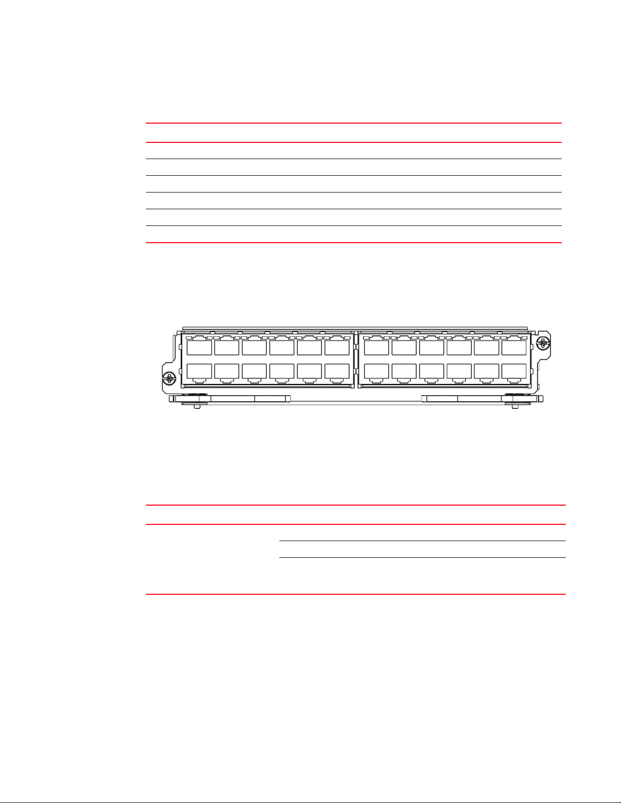
24-port 10/100/1000 Ethernet interface module
Figure 8 shows the front panel of the 24-port 10/100/1000 Ethernet RJ45 module.
FIGURE 8 24-port 10/100/1000 copper Ethernet module front panel
1
The front panel includes the following features:
• LEDs
• Twenty 10/100/1000 copper Ethernet ports.
Tab le 10 describes the 24-port 10/100/1000 Ethernet module LEDs.
TABLE 10 24-port 10/100/1000 Ethernet module LEDs
LED Position State Meaning
Link or
Active
Underneath the
ports. The top port
LED is on the left
side, the bottom
port LED is on the
right side.
On (solid) A link is established with the remote port (with no traffic).
Blinking The port is transmitting and receiving packets.
Off A link is not established with the remote port and no traffic
is being passed.
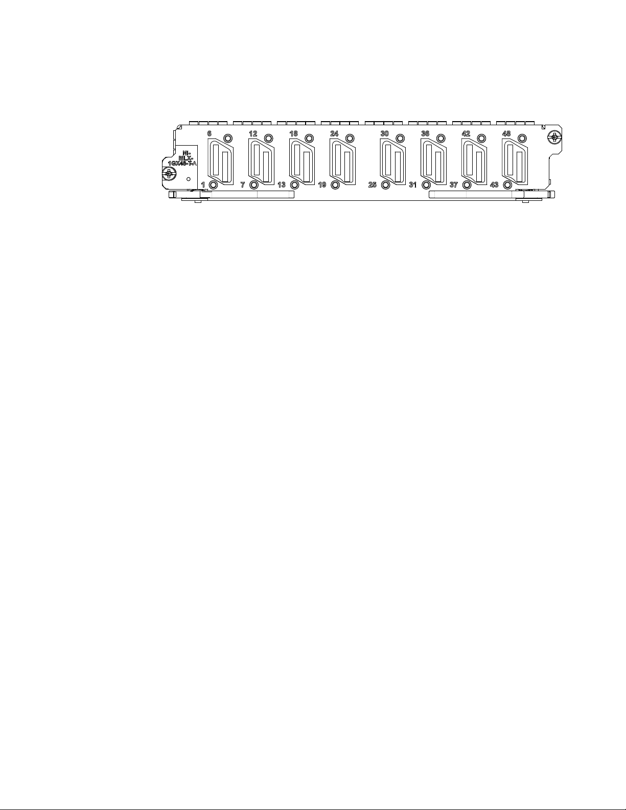
NI-MLX-1Gx48-T-A interface module
Figure 9 shows the front panel of the NI-MLX-1Gx48-T-A interface module.
PowerConnect B-MLXe Hardware Installation Guide 13
53-1002111-01
Page 26
Router modules
A
1
FIGURE 9 NI-MLX-1Gx48-T-A module front panel
The front panel includes the following features:
• A power LED located below the part number
• Eight mini-RJ21 connectors, each supporting six 10/100/1000 Mbps Ethernet ports
The eight mini-RJ21 connectors support six 1 Gbps Ethernet ports each. You can connect a patch
panel with a mini-RJ21 connector to a mini-RJ21 connector on the interface module. The patch
panel provides RJ45 connectors. You can also use a cable with a mini-RJ21 connector on one end
that connects to the mini-RJ21 connector on the interface module. The other end of the cable splits
into six cables with RJ45 connectors on each cable.
The NI-MLX-1Gx48-T-A module ships with two cable cinches. Each cable cinch consists of a plastic
part and a velcro strap. For instructions on using the cable cinches, see Chapter 3, “Using the Dell
Structured Cabling Components”.
Contact your Dell Sales Representative for more information about cables and patch panels that
support this module.
Power supply requirements for NI-MLX-1Gx48-T-A modules
When installing NI-MLX-1Gx48-T-A modules, consider the following power supply requirements for
each type of router:
• 4-slot routers
You can install up to three NI-MLX-1Gx48-T-A modules, and populate the remaining slots with
other modules using a single 1200W power supply. You can achieve a 1+2 power redundancy
by installing two additional power supplies.
If four NI-MLX-1Gx48-T-A modules are installed, you will need a minimum of two power
supplies. You can achieve 2+1 power redundancy by installing one additional power supply.
• 8-slot routers
You can install up to seven NI-MLX-1Gx48-T-A modules, and populate the remaining slots with
other modules using two 1200W power supplies. You can achieve a 2+2 power redundancy by
installing two additional power supplies.
If eight NI-MLX-1Gx48-T-A modules are installed, you will need a minimum of three power
supplies. You can achieve 3+1 power redundancy by installing one additional power supply.
• 16-slot routers
You can install up to twelve NI-MLX-1Gx48-T-A modules, and populate the remaining slots with
other modules using four 1200W power supplies. You can achieve a 4+4 power redundancy by
installing four additional power supplies.
14 PowerConnect B-MLXe Hardware Installation Guide
53-1002111-01
Page 27

Router modules
NOTE
1
If you install thirteen or more NI-MLX-1Gx48-T-A modules, you will need a minimum of five
power supplies. You can achieve 5+3 power redundancy by installing three additional power
supplies.
When installing NI-MLX-1Gx48-T-A modules, you must upgrade the software on all interface
modules and management modules to the appropriate software release. For more information
on the appropriate software release, refer to the Release Notes. For more information about
upgrading the software, refer to Chapter 6, “Upgrading Software Images and Configuration
Files”.
To display information about NIBI-16-FAN-EXH-A modules installed in a 16-slot router, enter the
show chassis command.
PowerConnect# show chassis
*** MLX-16 chassis ***
Power 1 (H1250CFN - AC 1200W): Installed (OK)
Power 2: Installed (Failed or Disconnected)
Power 3: not present
Power 4: Installed (Failed or Disconnected)
Power 5 (H1250CFN - AC 1200W): Installed (OK)
Power 6 (30351200 - AC 1200W): Installed (OK)
Power 7: Installed (Failed or Disconnected)
Power 8 (30351200 - AC 1200W): Installed (OK)
Total power budget for chassis = 4800 W
Total power used by system core = 762 W
Total power used by LPs = 1040 W
Total power available = 2998 W
Slot Power-On Priority and Power Usage:
Slot10 pri=1 module type=NI-MLX-1Gx48-T-A 48-port 10/100/1000Base-T MRJ21
Module power usage=260W
Slot11 pri=1 module type=NI-MLX-1Gx48-T-A 48-port 10/100/1000Base-T MRJ21
Module power usage=260W
Slot13 pri=1 module type=NI-MLX-1Gx48-T-A 48-port 10/100/1000Base-T MRJ21
Module power usage=260W
Slot16 pri=1 module type=NI-MLX-1Gx48-T-A 48-port 10/100/1000Base-T MRJ21
Module power usage=260W
--- FANS --Bottom fan tray (fan 1): Status = OK, Speed = LOW (50%)
Bottom fan tray (fan 2): Status = OK, Speed = LOW (50%)
Bottom fan tray (fan 3): Status = OK, Speed = LOW (50%)
Bottom fan tray (fan 4): Status = OK, Speed = LOW (50%)
Bottom fan tray (fan 5): Status = OK, Speed = LOW (50%)
Bottom fan tray (fan 6): Status = OK, Speed = LOW (50%)
To physically confirm the high speed fans look for the four captive screws on the fans at the
rear of the chassis.
Switch fabric modules
Tab le 11 lists the switch fabric modules that are available for PowerConnect B-MLXe routers.
PowerConnect B-MLXe Hardware Installation Guide 15
53-1002111-01
Page 28
Router modules
NOTE
Pwr
Active
BI-SWF
1
TABLE 11 Switch fabric modules
Part number Description
NI-X-4-HSF High speed switch fabric module for 4-slot routers
NI-X-16-8-HSF High speed switch fabric module for 8- and 16-slot routers
Switch fabric modules switch packets from one interface module to another. PowerConnect B-MLXe
routers can be configured with multiple switch fabric modules as described here:
• 4-slot router: Accommodates three switch fabric modules (two required and one redundant) for
a fully-loaded system. Ships with two switch fabric modules. You must purchase an additional
switch fabric module to equip your router for redundancy.
• 8-slot router: Accommodates three switch fabric modules (two required and one redundant) for
a fully-loaded system. Ships with two switch fabric modules. You must purchase an additional
switch fabric module to equip your router for redundancy.
• 16-slot router: Accommodates four switch fabric modules (three required and one redundant)
for a fully-loaded system. Ships with three switch fabric modules. You must purchase an
additional switch fabric module to equip your router for redundancy.
PowerConnect B-MLXe router switch fabric modules are dedicated, which means that they function
properly in PowerConnect B-MLXe routers only. If you attempt to install a PowerConnect B-MLXe
router switch fabric module in another Dell device or a switch fabric module intended for another
Dell device in a PowerConnect B-MLXe router, the router and switch fabric module will not function
properly.
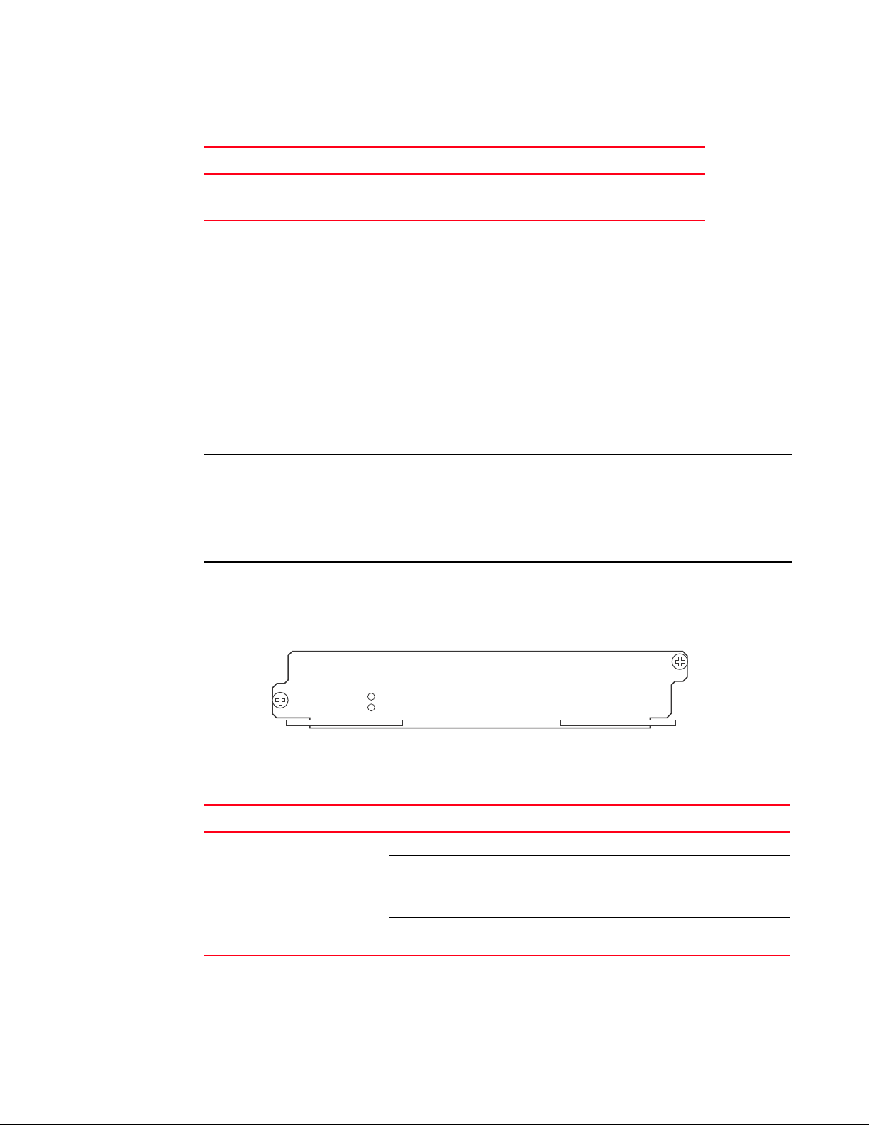
Figure 10 shows the front panel of a switch fabric module.
FIGURE 10 Switch fabric module front panel
l
The front panel contains two LEDs, as described in Table 12.
TABLE 12 Switch fabric module LEDs
LED Position State Meaning
Pwr Above Active LED On The module is receiving power.
Off The module is not receiving power.
Active Below Pwr LED On The switch fabric is active and ready to switch
user packets.
Off for an extended period The switch fabric is not active and cannot switch
user packets.
16 PowerConnect B-MLXe Hardware Installation Guide
53-1002111-01
Page 29

Router modules
NOTE
DANGER
1
High-speed switch fabric modules
Generation 2 (G2) high-speed fabric (HSF) modules support wire-speed forwarding for all packet
sizes, including jumbo frames.
HSF modules are supported on PowerConnect B-MLXe routers and are interoperable with all
existing interface modules.
HSF modules are hot-swappable, which allows you to install or replace them while the system is
powered up and running.
Power supplies
PowerConnect B-MLXe routers support the following power supply options:
• 4-slot router: Ships with one power supply, but can accommodate three AC power supplies (one
required and two redundant). To equip your router for redundancy, you must purchase one or
two additional power supplies.
• 8-slot router: Accommodates four AC power supplies (two required and two redundant).
Because power is supplied over a common power bus, any power supply installed in addition to
the two required will provide backup for any supply that fails. For full redundancy for both of the
required power supplies, you must add two additional power supplies.
• 16-slot router: Accommodates eight AC power supplies (four required and four redundant).
Because power is supplied over a common power bus, any power supply installed in addition to
the four required will provide backup for any power supply that fails. For full redundancy for all
of the required power supplies, you must add four additional power supplies.
For power supply specifications, refer to “Power specifications” on page 175.
Power supplies provide power to all router components, share the workload equally, and report
status to the management module. If the management module detects that a power supply has
failed or overheated, the management module redistributes the workload of the failed power
supply to the remaining power supplies.
Power supplies have three LEDs on the faceplate. These LEDs provide status for input power,
output power, and notification of alarms that have been sent. If the input power and output power
LEDs are on (a steady green), the power supply is providing power to the router components. For
more information about the power supply LEDs, refer to the AC power supply sections in Table 27
on page 207.
After a power supply is removed from a router, the software determines if there is enough power to
operate all of the interface modules. If it determines that there is not enough power, some interface
modules will be powered off.
Power supplies are hot-swappable, which means they can be removed and replaced while the
router is powered on and running. However, Dell recommends that you disconnect a power
supply from its power source before removing and replacing the supply. The 4-, 8-, and 16-slot
PowerConnect B-MLXe Hardware Installation Guide 17
53-1002111-01
Page 30
Router modules
1
1
router can be running while a power supply is being removed and replaced, but the power supply
itself should not be connected to a power source. Otherwise, you could be injured, or the power
supply or other parts of the router could be damaged.
Rack mounting brackets
All routers ship with pre-installed mounting brackets that allow you to front-mount the router in a
standard 19-inch (EIA310-D) rack. For instructions about how to mount the router in a rack, refer to
the installation chapter that is appropriate for your router model.
You can also mid-mount your 4-, 8- or 16-slot router using two L-shaped mounting brackets that
come in a mid-mount kit (ordered separately). The mid-mount kit comes with instructions for
installing the mounting brackets and mounting the router in a rack. Contact Dell for more
information about the mid-mount bracket kit.
Cooling system for PowerConnect B-MLXe routers
The cooling systems for PowerConnect B-MLXe routers contain the following components:
• 4-slot router: Equipped with a fan assembly that contains two 4-speed fans and two fan
controllers to support redundancy.
• 8-slot router: Equipped with a fan assembly containing four 4-speed fans and four fan
controllers to support redundancy.
• 16-slot router: Equipped with two high-speed fan assemblies. Each fan assembly contains two
4-speed fans with 16 fan controllers to support redundancy.
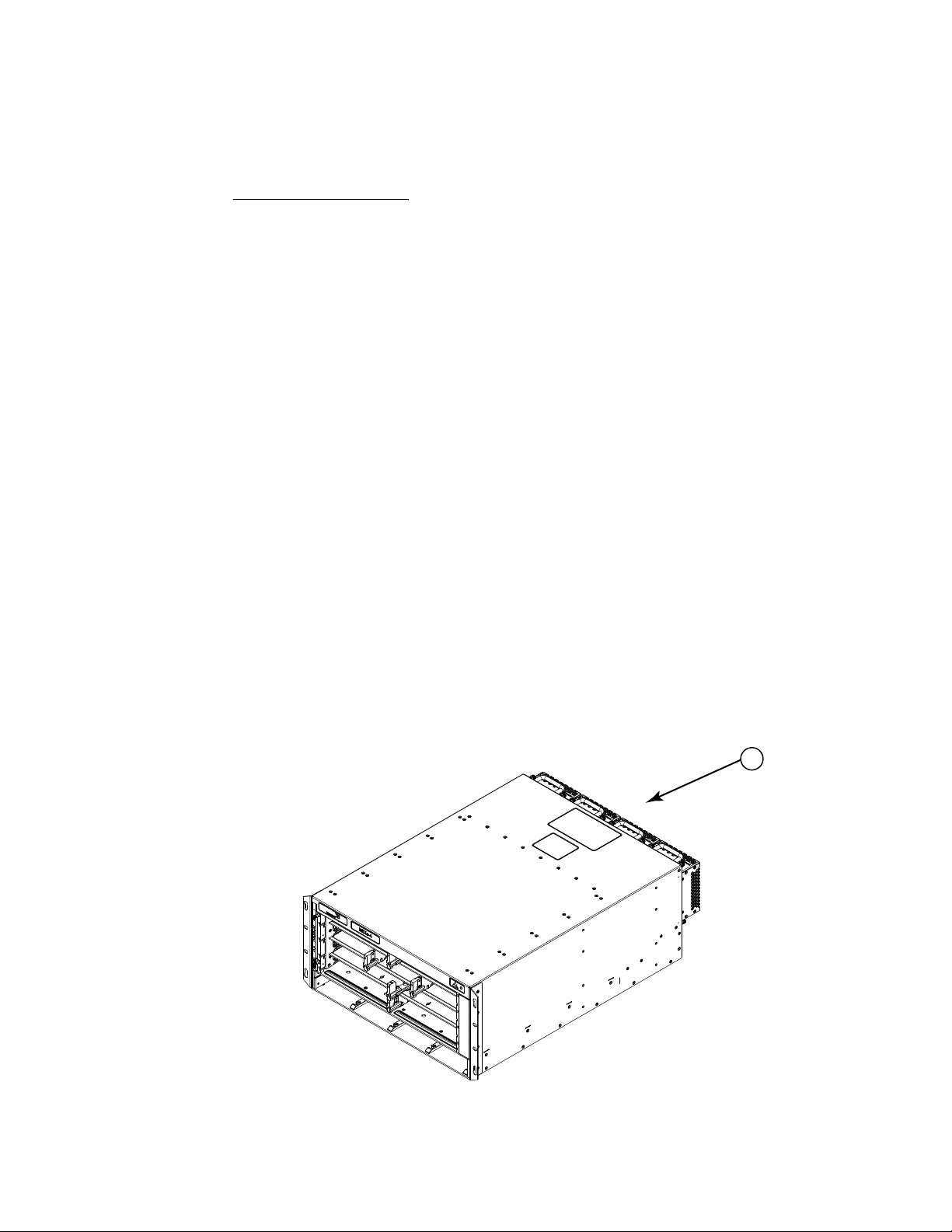
Figure 11 and Figure 12 show the fan locations for 4-slot and 8-slot routers. Figure 13 and
Figure 14 show the fan locations for 16-slot routers.
FIGURE 11 Fan locations for PowerConnect B-MLXe-4 routers
1 Fans in rear of chassis
18 PowerConnect B-MLXe Hardware Installation Guide
53-1002111-01
Page 31

FIGURE 12 Fan locations for PowerConnect B-MLXe-8-routers
1
1
Router modules
1
1Fan module
FIGURE 13 Fan location for PowerConnect B-MLXe-16 routers
1 Fan assembly
PowerConnect B-MLXe Hardware Installation Guide 19
53-1002111-01
Page 32

Router modules
1
1
FIGURE 14 Rear fan location for PowerConnect B-MLXe-16 routers
1 Rear fan assemblies
At startup, the fans operate at high speed. After a period of time, the management module
changes the fan speed to low.
By default, the router polls the temperature sensor on each module every 60 seconds for a
temperature reading. Depending on the results, the router will:
• Leave the fan speed as is
• Increase the fan speed
• Decrease the fan speed
• Shut down a module to prevent damage
If the temperature of a module exceeds specified high temperature thresholds, the system
generates a Syslog message and SNMP trap. The system can also shut down the module if the
temperature exceeds the highest threshold.
You can change default low and high temperature thresholds for modules and fan speeds. Refer to
“Changing temperature thresholds for modules and fan speeds” on page 107.
The fan control modules include a bi-color LED, which indicates the status of the fans. The router
ships with fan assemblies fully installed. Fan assemblies are hot-swappable, which means you can
remove and replace them without powering down the system.
NIBI-16-FAN-EXH-A high-speed fan assemblies
NIBI-16-FAN-EXH-A high-speed fan assemblies are required for PowerConnect B-MLXe routers when
you install NI-MLX-10Gx8-M, NI-MLX-10Gx8-D, or NI-MLX-1Gx48-T-A modules. PowerConnect
B-MLXe-16 routers ship with high-speed fan assemblies factory installed. Refer to “Installing
NIBI-16-FAN-EXH-A fan assemblies” on page 167 for high-speed fan installation instructions.
20 PowerConnect B-MLXe Hardware Installation Guide
53-1002111-01
Page 33

Rack mount kit
PowerConnect B-MLXe routers can be mounted in a standard 19-inch (EIA310-D) rack, and ship
with pre-installed mounting brackets.
You can install the following number of routers in a rack depending on the model:
• 4-slot router – Up to ten routers per rack
• 8-slot router – Up to six routers per rack
• 16-slot router – Up to three routers per rack
For instructions on how to install routers in a rack, refer to Chapter 2, “Installing a PowerConnect
B-MLXe Core Router”.
Supported software features
For a complete list of software features supported on PowerConnect B-MLXe routers, refer to the
software release notes.
Supported software features
1
PowerConnect B-MLXe Hardware Installation Guide 21
53-1002111-01
Page 34

Supported software features
1
22 PowerConnect B-MLXe Hardware Installation Guide
53-1002111-01
Page 35

Chapter
DANGER
DANGER
CAUTION
CAUTION
CAUTION
CAUTION
Installing a PowerConnect B-MLXe Core Router
Installation precautions
Read the following cautions and danger notices before installing PowerConnect B-MLXe routers.
General precautions
The procedures in this manual are for qualified service personnel.
All fiber-optic interfaces use Class 1 Lasers.
2
Do not install the router in an environment where the operating ambient temperature might
exceed 40C (104F).
Make sure the air flow around the front, sides, and back of the router is not restricted.
If you do not install a module in a slot, you must keep the slot blank in place. If you operate the
router with an uncovered slot, the system may overheat.
Never leave tools inside the router.
PowerConnect B-MLXe Hardware Installation Guide 23
53-1002111-01
Page 36

Installation precautions
CAUTION
DANGER
DANGER
DANGER
DANGER
DANGER
DANGER
2
Power precautions
Use a separate branch circuit for each AC power cord for redundancy in case one of the circuits
fails.
Make sure to choose the appropriate circuit device, depending on the number of AC power
supplies installed in the router.
Disconnect the power cord from all power sources to completely remove power from the router.
Make sure that the power source circuits are properly grounded, then use the power cord
supplied with the router to connect it to the power source.
If the installation requires a different power cord than the one supplied with the router, make
sure you use a power cord displaying the mark of the safety agency that defines the regulations
for power cords in your country. The mark is your assurance that the power cord can be used
safely with the router.
Make sure the rack or cabinet housing the router is adequately secured to prevent it from
becoming unstable or falling over.
Mount the routers you install in a rack or cabinet as low as possible. Place the heaviest router at
the bottom and progressively place lighter routers above.
24 PowerConnect B-MLXe Hardware Installation Guide
53-1002111-01
Page 37

Installing a PowerConnect B-MLXe-4 router
CAUTION
CAUTION
CAUTION
CAUTION
CAUTION
Ensure that the router does not overload the power circuits, wiring, and over-current protection.
To determine the possibility of overloading the supply circuits, add the ampere (amp) ratings of all
devices installed on the same circuit as the router. Compare this total with the rating limit for the
circuit. The maximum ampere ratings are usually printed on the routers near the input power
connectors.
PowerConnect B-MLXe routers with AC power sources are intended for installation in restricted
access areas only. A restricted access area is a location where access can be gained only by
service personnel through the use of a special tool, lock and key, or other means of security.
For the DC input circuit to the system of PowerConnect B-MLXe-4. PowerConnect B-MLXe-8, and
PowerConnect B-MLXe-16 routers (1800W supply), make sure there is a UL-Listed 60 amp circuit
breaker, minimum -48VDC, double pole, on the input lugs to the power supply. The input wiring
for connection to the product should be copper wire, 6 AWG, marked VW-1, and rated minimum
90C.
2
For the DC input circuit to the system of PowerConnect B-MLXe-4. PowerConnect B-MLXe-8, and
PowerConnect B-MLXe-16 routers (1200W supply), make sure there is a UL-Listed 30 amp circuit
breaker, minimum -48VDC, double pole, on the input lugs to the power supply. The input wiring
for connection to the product should be copper wire, 6 AWG, marked VW-1, and rated minimum
90C.
For the NEBS-compliant installation of PowerConnect B-MLXe-4, PowerConnect B-MLXe--8, and
PowerConnect B-MLXe-16 routers with AC systems, use a ground wire of at least 6 American Wire
Gauge (AWG). The ground wire should have an agency-approved crimped connector (provided
with the device) attached to one end, with the other end attached to building ground. The
connector must be crimped with the proper tool, allowing it to be connected to both ground
screws on the enclosure. Before crimping the ground wire into the provided ground lug, ensure
the bare copper wire has been cleaned and antioxidant is applied to the bare wire.
Installing a PowerConnect B-MLXe-4 router
This section describes how to install a PowerConnect B-MLXe-4 router.
PowerConnect B-MLXe Hardware Installation Guide 25
53-1002111-01
Page 38

Installing a PowerConnect B-MLXe-4 router
NOTE
NOTE
NOTE
2
Illustrations in this chapter may differ slightly from the actual equipment.
Preparing the installation site
Before installing the router, plan the location and orientation relative to other devices and
equipment. For cooling purposes, allow a minimum of six inches of space between the sides, front,
and the back of the router and walls or other obstructions. If a router is installed in a perforated
enclosure, the perforations must cover at least 60 percent of the surface.
This equipment is suitable for installation in a Network Telecommunication facility and where NEC
requirements apply. Additionally, it may be installed in either a Common Bonding Network (CBN) or
Isolated Bonding Network (IBN). It is not intended for Outside Plant (OSP) installations.
Ensure that the proper cabling is installed at the site.
For information on cabling, refer to “Installing power supplies in a PowerConnect B-MLXe-4 router”
on page 38, “Attaching a management station” on page 68, and “Connecting the router to a
network device” on page 95.
Unpacking a PowerConnect B-MLXe-4 router
The PowerConnect B-MLXe-4 router ships with the following items:
• Router chassis with switch fabric modules installed in slots marked SF, slot blanks installed in
all empty module slots, and mounting brackets attached for front-mount.
• Insertion or extraction tool for use with RJ45 and fiber-optic connectors.
If any items are missing, contact the place of purchase.
Unpacking steps
Follow these steps to unpack your PowerConnect B-MLXe-4 router.
1. Remove the router from the shipping carton.
2. Save the shipping carton and packing materials in case you need to move or ship the router at
a later time.
Installing a PowerConnect B-MLXe-4 router in a rack or cabinet
Your PowerConnect B-MLXe-4 router ships from the factory with mounting brackets attached. You
can mount your router in the following ways:
• Front-mount in a standard two-post rack using the factory-installed brackets.
• Mid-mount in a standard two-post rack by moving the factory-installed brackets to the center of
the device
• Mount the device in a four-post rack or cabinet using the Cabinet Mount Kit. Refer to
“Mounting in a 4-post rack or cabinet” on page 29.
26 PowerConnect B-MLXe Hardware Installation Guide
53-1002111-01
Page 39

Installing a PowerConnect B-MLXe-4 router
NOTE
NOTE
Because of the weight of a fully loaded PowerConnect B-MLXe-4 router, Dell recommends mounting
it in a rack before installing the modules and AC power supplies.
You can install up to eight PowerConnect B-MLXe-4 routers in a standard 19-inch (EIA310-D)
two-post rack using the factory-installed mounting brackets for either front- or mid-mounts.
If you use the air duct rack mount method, you can install up to six PowerConnect B-MLXe-4 routers
in a cabinet or four-post rack using the cabinet mounting kit.
Mounting your device in a standard rack
The factory-installed mounting brackets allow you to front-mount or mid-mount your device in the
rack. For a mid-mount, you must remove the factory installed brackets from the front edge of the
device and install them using the holes in the center-sides of the device. Refer to Figure 16.
You will need to provide four standard #12-24 pan-head screws (per router) to secure routers in the
rack. You will also need a #2 Phillips screwdriver. Complete the following steps.
When connecting the device to the rack frame, use thread-forming screws and paint-piercing
washers.
2
1. Determine the position of each router in the rack according to the weight of the router. For
example, mount the router with the fewest modules near the top of the rack, a router with more
modules near the middle of the rack, and fully populated routers near the bottom of the rack.
2. Using the keyhole slots in the router mounting brackets as a guide, align one screw per rack
post, as shown in Figure 33. On one side of the rack, the screw should align with the top hole in
the mounting bracket. On the other side of the rack, the screw should align with the bottom
hole of the mounting bracket. When tightening these screws, leave approximately 1/4 inch of
clearance between the back of the screw head and the rack post.
PowerConnect B-MLXe Hardware Installation Guide 27
53-1002111-01
Page 40

Installing a PowerConnect B-MLXe-4 router
5"
3"
1 2
1
1
2
3
2
FIGURE 15 Positioning the mounting screws in rack posts
1 Unequal flange equipment rack 2 Network equipment rack
3. Mount the lowest router first. With one person on each side, lift the router and slip the widest
part of each keyhole slot on the mounting bracket over the corresponding screw in the rack
post. See Figure 33.
FIGURE 16 Mounting the router in a rack
1 Screws on mounting posts 2 Front-mount position 3 Mid-mount position
4. Slide the router down so that the mounting screw heads are in the narrowest part of the
keyhole slots.
5. Tighten the screws to secure the router in place. For extra support, use additional screws.
28 PowerConnect B-MLXe Hardware Installation Guide
53-1002111-01
Page 41

Installing a PowerConnect B-MLXe-4 router
NOTE
For better grounding of the router to the rack, attach the router using n t. You should also use star
washers with any single-hole grounding lugs to keep the lugs from rotating.
6. Repeat step 2 through step 5 to mount each router in the rack, moving from lowest to highest.
2
Mounting in a 4-post rack or cabinet
You can also install your device in a 4-post rack or cabinet, using a Cabinet Rack Mount Kit, which
must be ordered separately (part number F899W). This kit includes the following hardware:
• Cabinet Mount Kit contents:
- Front mounting brackets (2)
- Side mounting plates (2)
- Rear brackets (4)
- Telescoping rack mount shelf
- Side duct assembly
- Top rails - 2 for use in 29-31” rack and 2 for use in 27-29” rack
- 18 6-32 flat head screws
- 12 10-32 screws
- 12 10-32 Slip and Caged Nuts.
To order the Cabinet Rack Mount Kit, contact Dell.
Cabinet rack mounting steps
Follow these steps to mount each PowerConnect B-MLXe-4 router in a rack using the cabinet
mounting kit, starting with the lowest device first.
1. Determine the position of each router in the rack according to the weight of the router. For
example, mount the router with the fewest modules near the top of the rack, the router with
more modules near the middle of the rack, and a fully populated router near the bottom of the
rack.
2. Remove the factory-installed mounting brackets from the chassis.
3. Attach the front mounting brackets to the chassis using 8 6-32 flat head screws. Refer to
Figure 17.
PowerConnect B-MLXe Hardware Installation Guide 29
53-1002111-01
Page 42

Installing a PowerConnect B-MLXe-4 router
A
B
B
A
2
FIGURE 17 Attach front mounting brackets to the chassis
4. Attach the side plates to the rear of the chassis. Refer to Figure 18.
FIGURE 18 Attach the side plates to the rear of the chassis
5. Install the mounting shelf to the rack rails. Refer to Figure 19.
30 PowerConnect B-MLXe Hardware Installation Guide
53-1002111-01
Page 43

Installing a PowerConnect B-MLXe-4 router
FIGURE 19 Install the mounting shelf in the rack
6. Install the side ducts to the mounting shelf. Refer to Figure 20. Facing the port side of the
router, the side ducts will be on one left side of router.
FIGURE 20 Install side air ducts to the mounting shelf
2
7. Install the top rails to the rack. Refer to Figure 21.
PowerConnect B-MLXe Hardware Installation Guide 31
53-1002111-01
Page 44

Installing a PowerConnect B-MLXe-4 router
1
2
FIGURE 21 Install top rails to the rack
8. Install the device in the rack. The device slides into the rack on top of the mounting shelf.
Secure the device to the rack rails using 10-32 screws. Refer to Figure 22.
32 PowerConnect B-MLXe Hardware Installation Guide
53-1002111-01
Page 45

FIGURE 22 Mounting the router in a rack
NOTE
Installing a PowerConnect B-MLXe-4 router
2
9. Install the rear brackets to the rack and to the chassis side plates. Refer to Figure 23.
Rear brackets are required for NEBS-compliant installations.
PowerConnect B-MLXe Hardware Installation Guide 33
53-1002111-01
Page 46

Installing a PowerConnect B-MLXe-4 router
NOTE
DANGER
NOTE
2
FIGURE 23 Install the rear brackets to the rack and chassis side plates
Repeat steps 2 through 8 to install each router in the rack, moving from lowest to highest.
Installing PowerConnect B-MLXe-4 modules
The sequence for installing multiple modules is important to ensure proper fit. The recommended
sequence for the PowerConnect B-MLXe-4 router is to install right-to-left, beginning with the lowest
row and moving up.
Installation procedures are identical for interface, management and switch fabric modules.
The intra-building ports of the equipment or subassembly is suitable for connection to
intra-building or unexposed wiring or cabling only. The intra-building ports of the equipment or
subassembly MUST NOT be metallically connected to interfaces that connect to the outside plant
(OSP) or its wiring. These interfaces are designed for use as intra-building interfaces only (Type 2
or Type 4 ports as described in GR-1089-CORE, Issue 4) and require isolation from the exposed
OSP cabling. The addition of Primary Protectors is not sufficient protection in order to connect
these interfaces metallically to OSP wiring.
PowerConnect B-MLXe modules are dedicated, which means that you must install them in
PowerConnect B-MLXe routers only. If you install a PowerConnect B-MLXe module in a
non-PowerConnect B-MLXe router, or install a module intended for a non-PowerConnect B-MLXe
router in a PowerConnect B-MLXe router, the router and module will not function properly.
For information about how to disable and re-enable power to interface modules, see “Disabling and
re-enabling power to interface modules” on page 99
Tab le 13 identifies the router slot numbers where the modules must be installed. An identifying
label can be seen at the base of each slot.
34 PowerConnect B-MLXe Hardware Installation Guide
53-1002111-01
Page 47

Installing a PowerConnect B-MLXe-4 router
NOTE
CAUTION
NOTE
DANGER
NOTE
DANGER
The PowerConnect B-MLXe-4 router ships with the required switch fabric modules installed.
2
TABLE 13 PowerConnect B-MLXe-4 module installation
module slot number
Management modules Active module – M1 (left).
Redundant module – M2 (right).
Interface modules 1 – 4
Switch fabric modules SF1 – SF3
If you do not install a module in a slot, you must leave the slot blank installed in the slot. If you
run the router with an uncovered slot, the system may overheat.
If you are installing a redundant management module, see the chapter titled “Using a Redundant
Management Module” in the Brocade NetIron Configuration Guide for information about how the
redundant module works, optional software configurations, and how to manage redundancy.
Before installing modules, have the following items available:
• A large flat-blade screwdriver.
• An ESD wrist strap with a plug for connection to the ESD connector on the router chassis.
For safety reasons, the ESD wrist strap should contain a 1 megohm series resistor.
Installation instructions are identical for interface, management, and switch fabric modules.
You can install modules while the router is powered on and running.
Before installing a new interface module, you will need to remove the slot blank from the module
slot. You should also have the following items available:
• A 1/4 inch #8 flat-blade screwdriver, or a #2 Phillips screwdriver
• A new interface module, which you can order from Dell
• An ESD wrist strap with a plug for connection to the ESD connector on the PowerConnect
B-MLXe router.
For safety reasons, the ESD wrist strap should contain a 1 megohm series resistor.
PowerConnect B-MLXe Hardware Installation Guide 35
53-1002111-01
Page 48

Installing a PowerConnect B-MLXe-4 router
CAUTION
CAUTION
2
The PowerConnect B-MLXe-4 router ships with slot blanks installed in all empty module slots. The
slot blanks help ensure proper airflow inside the router. You must remove the slot blank to install a
module into a slot.
If you do not install a module in a slot, you must keep the slot blank in place. If you operate the
router with an uncovered slot, the system may overheat. Tighten the screws that secure the slot
blanks so that they remain in place when removing adjacent panels or modules.
Although the slot blanks differ in size, the procedure for removing them is identical. You will need a
flat-blade screwdriver to remove slot blanks.
Slot blank removal steps
Follow these steps to remove a slot blank.
1. Loosen the screws on either end of the slot blank by hand or with a flat-blade screwdriver.
2. Pull the slot blank out of the router, and store it in a safe place for future use.
If you are hot-swapping a module, allow a minimum of two seconds after a module (or power
supply or fan tray) has been removed before inserting a module in the same slot.
Module installation steps
Follow these steps to install a module.
1. If you are installing a module in a slot which may have been configured for a different module
type, remove the old configuration information by following these steps.
a. Use the show running-config command in config mode to determine the current
configuration of the slot.
PowerConnect(config)# show running-config
Current configuration:
!
ver V5.1.0aT163
module 1 ni-mlx-24-port-1g-copper
!
This example shows that slot 1 has already been configured for a 24-port 1 Gbps copper
interface module.
b. Enter the no module <slot-number> <module-type> command to remove the configuration
from slot 1, using the information shown as a result of the show running-config command.
PowerConnect(config)# no module 1 ni-mlx-24-port-1g-copper
This example removes the existing configuration from slot 1, leaving it ready for a new
module.
2. Put on the ESD wrist strap and ground yourself by inserting the plug into the ESD connector on
the front of the chassis.
3. Remove the module from the packaging.
36 PowerConnect B-MLXe Hardware Installation Guide
53-1002111-01
Page 49

Installing a PowerConnect B-MLXe-4 router
NOTE
4. Insert the module into the router slot, and slide the card along the card guide until the ejectors
on either side of the module move close to the module front panel. Refer to Figure 24.
When inserting the module into the router, be sure that the faceplate does not overlap the
faceplate of an adjacent module.
5. Rotate the ejectors until they are flush with the module front panel. This action will fully seat
the module in the backplane.
6. Tighten the screws at each end of the module faceplate by pushing them in and turning them
clockwise. Complete the tightening process using the flat-blade screwdriver.
7. En te r t h e write memory command to ensure that the slot will be correctly configured for the
new module after a reboot.
PowerConnect(config)# write memory
Write startup-config done.
2
FIGURE 24 Installing a module
NI-MLX-1Gx48-T-A interface module power supply requirements
A single 1200W power supply will support up to three NI-MLX-1Gx48-T-A modules, with other
modules filling the remaining slots. You can equip your router for 1+2 power redundancy by
installing up to two additional power supplies.
If you install four NI-MLX-1Gx48-T-A modules in your router, you will need a minimum of two power
supplies. You can equip your router for 2+1 power redundancy by installing one additional power
supply.
PowerConnect B-MLXe Hardware Installation Guide 37
53-1002111-01
Page 50

Installing a PowerConnect B-MLXe-4 router
NOTE
CAUTION
2
NI-MLX-8x10-M interface module power supply, switch fabric,
and fan requirements
A single 1200W power supply will support up to three NI-MLX-8x10-M modules, with other modules
filling the remaining slots. You can equip your router for 1+2 power redundancy by installing up to
two additional power supplies.
If you install four NI-MLX-8x10-M modules in your router, you will need a minimum of two power
supplies. You can equip your router for 2+1 power redundancy by installing one additional power
supply.
Installing power supplies in a PowerConnect B-MLXe-4 router
The PowerConnect B-MLXe-4 router ships with one power supply, but can accommodate up to three
AC power supplies (one required and two redundant). To equip your router for redundancy, you will
need to purchase one or two additional power supplies.
Power supply installation steps
Follow these steps to install a power supply.
1. Remove the power supply slot blank and store it for future use.
2. Remove the power supply from the packaging.
3. Insert the power supply into the slot and slide it along the guides on each side of the slot. Refer
to Figure 25.
Empty power supply slots must be covered with slot blanks.
Carefully follow the mechanical guides on each side of the power supply slot and make sure the
power supply is properly inserted in the guides. Never insert the power supply upside down.
38 PowerConnect B-MLXe Hardware Installation Guide
53-1002111-01
Page 51

Installing a PowerConnect B-MLXe-4 router
NOTE
DANGER
FIGURE 25 Installing a power supply
4. Push the power supply front panel into the router until it engages the backplane connector.
2
5. Ensure captive pin is engaged.
For information about connecting power to the router, refer to “Connecting AC power” on page 39.
Connecting AC power
AC power is supplied through a power cord connected to the AC power supply installed in the router.
For the NEBS-compliant installation, AC power connections must use a surge protection device
(SPD) to protect the AC power supplies from damage due to excessive power line surges.
AC power connection steps
Follow these steps to connect the AC power cord.
1. Locate the power receptacle on the rear side of the chassis.
2. Lift the cord retainer and connect an AC power cord to the power supply.
3. Snap the cord retainer over the power plug to hold it in place.
If the installation requires a different power cord than the one supplied with the router, make
sure you use a power cord displaying the mark of the safety agency that defines the regulations
for power cords in your country. The mark is your assurance that the power cord can be used
safely with the router.
For information about powering on the system, refer to “Activating the power source” on page 69.
PowerConnect B-MLXe Hardware Installation Guide 39
53-1002111-01
Page 52

Installing a PowerConnect B-MLXe-8 router
NOTE
NOTE
2
Final steps
Complete these steps in the order listed:
• “Attaching a management station”
• “Activating the power source”
• “Verifying proper operation”
Installing a PowerConnect B-MLXe-8 router
This section describes how to install a PowerConnect B-MLXe-8 router.
Illustrations in this chapter may differ slightly from the actual equipment.
Preparing the installation site
Before installing the router, plan the location and orientation relative to other devices and
equipment. For cooling purposes, allow a minimum of six inches of space between the sides, front,
and the back of the router and walls or other obstructions. If a router is installed in a perforated
enclosure, the perforations must cover at least 60 percent of the surface.
This equipment is suitable for installation in a Network Telecommunication facility and where NEC
requirements apply. Additionally, it may be installed in either a Common Bonding Network (CBN) or
Isolated Bonding Network (IBN). It is not intended for Outside Plant (OSP) installations.
Ensure that the proper cabling is installed at the site.
For information on cabling, refer to “Installing power supplies in the PowerConnect B-MLXe-8
router” on page 51, “Attaching a management station” on page 68, and “Connecting the router to a
network device” on page 95.
Unpacking a PowerConnect B-MLXe-8 router
The PowerConnect B-MLXe-8 router ships with the following items:
• Switch fabric modules installed in slots marked SF, and slot blanks installed in all empty
module slots.
• Two AC power supplies
• Insertion or extraction tool for use with RJ45 and fiber-optic connectors.
Save the shipping carton and packing materials in case you need to move or ship the router at a
later time.
Lifting guidelines for PowerConnect B-MLXe-8 routers
Follow these guidelines for lifting and moving PowerConnect B-MLXe-8 routers:
• Before lifting or moving the router, disconnect all external cables.
40 PowerConnect B-MLXe Hardware Installation Guide
53-1002111-01
Page 53

Installing a PowerConnect B-MLXe-8 router
NOTE
2
• Do not attempt to lift a fully configured router by yourself.
• It is recommended that you install router components after you have installed the router in a
rack.
Installing a PowerConnect B-MLXe-8 router in a rack
Because of the weight of a fully loaded PowerConnect B-MLXe-8 router, Dell recommends mounting
it in a rack before installing the modules and AC power supplies.
You can install up to six PowerConnect B-MLXe-8 routers in a standard 19-inch (EIA310-D) rack
using the standard rack installation method. If you use the cabinet mounting kit, you can install up
to 4 PowerConnect B-MLXe-8 routers in a standard 19-inch rack.
Front- or mid-mount your device in a standard rack
Your PowerConnect B-MLXe-8 router ships from the factory with mounting brackets attached for
front-mount installation in a standard rack. You can also use these brackets for a mid-mount
installation by simply removing the brackets from the front edges of the device and re-attaching
them in the center sides of the device using the pre-drilled holes. Refer to Figure 27.
You will need to provide four standard #12-24 pan-head screws (per router) and a #2 Phillips
screwdriver to secure routers in the rack.
When connecting the device to the rack frame, use thread-forming screws and paint-piercing
washers.
Follow these steps to mount your device in a standard rack in either a front- or mid-mount
configuration.
1. Determine the position of each router in the rack according to weight. For example, mount the
router with the fewest modules near the top of the rack, the router with more modules near the
middle of the rack, and a fully populated router near the bottom of the rack.
2. Using the keyhole slots in the router mounting brackets as a guide, align one screw per rack
post, as shown in Figure 26. On one side of the rack, the screw should align with the top hole in
the mounting bracket. On the other side of the rack, the screw should align with the bottom
hole of the mounting bracket. When tightening these screws, leave approximately 1/4 inch of
clearance between the back of the screw head and the rack post.
PowerConnect B-MLXe Hardware Installation Guide 41
53-1002111-01
Page 54

Installing a PowerConnect B-MLXe-8 router
5"
3"
1 2
1
2
3
1
2
FIGURE 26 Positioning the mounting screws in rack posts
1 Unequal flange equipment rack 2 Network equipment rack
3. Mount the lowest router first. With one person on each side, lift the router and slip the widest
part of each keyhole slot on the mounting bracket over the corresponding screw in the rack
post. See Figure 27.
FIGURE 27 Mounting the router in a rack
1 Screws in mounting posts 2 Front-mount position installation 3 Mid-mount installation
4. Slide the router down so that the mounting screw heads are in the narrowest part of the
keyhole slots.
5. Tighten the screws to secure the router in place. For extra support, use additional screws.
42 PowerConnect B-MLXe Hardware Installation Guide
53-1002111-01
Page 55

Installing a PowerConnect B-MLXe-8 router
NOTE
For better grounding of the router to the rack, attach the router using star washers. You should also
use star washers with any single-hole grounding lugs to keep the lugs from rotating.
Repeat step 2 through step 5 to mount each router in the rack, moving from lowest to highest.
2
Mounting your device in a cabinet
You can also install your device in a 4-post rack or cabinet, using a Cabinet Rack Mount Kit, which
must be ordered separately (part number VW8MK). This kit includes the following hardware:
• Cabinet Mount Kit contents:
- Front mounting brackets (2)
- Side mounting plates (2)
- Rear brackets (4)
- Telescoping rack mount shelf
- Side duct assembly
- Top rails - 2 for use in 29-31” rack and 2 for use in 27-29” rack
- 18 6-32 flat head screws
- 12 10-32 screws
- 12 10-32 slip and caged nuts
To order the Cabinet Rack Mount Kit, contact Dell.
Cabinet rack mounting steps
Follow these steps to mount each PowerConnect B-MLXe-8 router in a rack using the Cabinet Rack
Mount Kit, starting with the lowest device first.
1. Determine the position of each router in the rack according to the weight of the router. For
example, mount the router with the fewest modules near the top of the rack, the router with
more modules near the middle of the rack, and a fully populated router near the bottom of the
rack.
2. Remove the factory-installed mounting brackets from the chassis.
3. Attach the kit front mounting brackets to the chassis using 8 6-32 flat head screws. Refer to
Figure 17.
PowerConnect B-MLXe Hardware Installation Guide 43
53-1002111-01
Page 56

Installing a PowerConnect B-MLXe-8 router
2
FIGURE 28 Attach front mounting brackets to the chassis
4. Attach the side plates to the rear of the chassis. Refer to Figure 29.
44 PowerConnect B-MLXe Hardware Installation Guide
53-1002111-01
Page 57

Installing a PowerConnect B-MLXe-8 router
FIGURE 29 Attach the side plates to the rear of the chassis
2
5. Install the mounting shelf to the rack rails. Refer to Figure 30.
FIGURE 30 Install the mounting shelf in the rack
6. Install the side ducts to the mounting shelf. Refer to Figure 31. Facing the port side of the
router, the side ducts will be on the left side of the router.
PowerConnect B-MLXe Hardware Installation Guide 45
53-1002111-01
Page 58

Installing a PowerConnect B-MLXe-8 router
1
2
FIGURE 31 Install side air ducts to the mounting shelf
7. Install the top rails to the rack. Refer to Figure 32.
FIGURE 32 Install top rails to the rack
8. Install the device in the rack. The device slides into the rack on top of the mounting shelf.
Secure the device to the rack rails using 10-32 screws. Refer to Figure 33.
46 PowerConnect B-MLXe Hardware Installation Guide
53-1002111-01
Page 59

FIGURE 33 Mounting the router in the cabinet
Installing a PowerConnect B-MLXe-8 router
2
9. Install the rear brackets to the rack and to the chassis side plates. Refer to Figure 34
FIGURE 34 Install the rear brackets to the rack and chassis side plates
Repeat steps 2 through 8 to install each router in the rack, moving from lowest to highest.
PowerConnect B-MLXe Hardware Installation Guide 47
53-1002111-01
Page 60

Installing a PowerConnect B-MLXe-8 router
NOTE
DANGER
NOTE
NOTE
CAUTION
2
Installing PowerConnect B-MLXe-8 modules
The sequence for installing multiple modules is important to ensure proper fit. The recommended
sequence for the PowerConnect B-MLXe-8 router is to install right-to-left, beginning with the lowest
row and moving up.
installation instructions are identical for interface, management, and switch fabric modules.
The intra-building ports of the equipment or subassembly are suitable for connection to
intra-building or unexposed wiring or cabling only. The intra-building ports of the equipment or
subassembly MUST NOT be metallically connected to interfaces that connect to the outside plant
(OSP) or its wiring. These interfaces are designed for use as intra-building interfaces only (Type 2
or Type 4 ports as described in GR-1089-CORE, Issue 4) and require isolation from the exposed
OSP cabling. The addition of Primary Protectors is not sufficient protection in order to connect
these interfaces metallically to OSP wiring.
PowerConnect B-MLXe modules are dedicated, which means that you must install them in the
PowerConnect B-MLXe router only. If you try to install a PowerConnect B-MLXe module in a
non-PowerConnect B-MLXe router, or install a module intended for a non-PowerConnect B-MLXe
router in a PowerConnect B-MLXe router, the router and module will not function properly.
Tab le 14 identifies the router slot numbers where the modules must be installed. An identifying
label can be seen at the base of each slot.
For information about how to disable and re-enable power to interface modules, see “Disabling and
re-enabling power to interface modules” on page 99
The PowerConnect B-MLXe-8 router ships with the required switch fabric modules installed.
TABLE 14 PowerConnect B-MLXe-8 module slot designations
Module Slot number
Management modules Active module – M1 (left).
Redundant module – M2 (right).
Interface modules 1 – 8
Switch fabric modules SF1 – SF3
If you do not install a module in a slot, you must leave the slot blank installed in the slot. If you
run the router with an uncovered slot, the system may overheat.
48 PowerConnect B-MLXe Hardware Installation Guide
53-1002111-01
Page 61

Installing a PowerConnect B-MLXe-8 router
NOTE
DANGER
CAUTION
CAUTION
If you are installing a redundant management module, refer to the chapter titled “Using a Redundant
Management Module” in the PowerConnect B-MLXe Configuration Guide for information about how
the redundant module works, optional software configurations, and how to manage redundancy.
Before installing a module in the PowerConnect B-MLXe-8 router, have the following items
available:
2
• A large flat-blade screwdriver.
• An ESD wrist strap with a plug for connection to the ESD connector on the router.
For safety reasons, the ESD wrist strap should contain a 1 megohm series resistor.
You can install modules while the router is powered on and running.
The router ships with slot blanks installed in all empty module slots. The slot blanks help ensure
proper airflow inside the router. You must remove the slot blank to install a module.
If you do not install a module in a slot, you must keep the slot blank in place. If you run the router
with an uncovered slot, the system may overheat. Tighten the screws that secure the slot blanks
so that they remain in place when removing adjacent panels or modules.
Although the slot blanks differ in size, the procedure for removing them is identical. You will need a
flat-blade screwdriver to perform this task.
Slot blank removal steps
Follow these steps to remove a slot blank.
1. Loosen the screws on either end of the slot blank by hand or with a flat-blade screwdriver.
2. Pull the slot blank out of the router, and store it in a safe place for future use.
If you are hot-swapping a module, allow a minimum of two seconds after a module (or power
supply or fan tray) has been removed before inserting a module in the same slot.
Module installation steps
Follow this procedure to install a module in the router.
1. If you are installing a module in a slot which may have been configured for a different module
type, remove the old configuration information by following these steps.
a. Use the show running-config command in config mode to determine the current
configuration of the slot.
PowerConnect(config)# show running-config
Current configuration:
PowerConnect B-MLXe Hardware Installation Guide 49
53-1002111-01
Page 62

Installing a PowerConnect B-MLXe-8 router
NOTE
2
!
ver V5.1.0aT163
module 1 ni-mlx-24-port-1g-copper
!
This example shows that slot 1 has already been configured for a 24-port 1 Gbps copper
interface module.
Enter the no module <slot-number> <module-type> command to remove the configuration
from slot 1. Use the slot number and module type shown in the output from the show
running-config command.
PowerConnect(config)# no module 1 ni-mlx-24-port-1g-copper
This example removes the configuration from slot 1, leaving it ready for a new module.
2. Put on the ESD wrist strap and ground yourself by inserting the plug into the ESD connector on
the chassis.
3. Remove the module from the packaging.
4. Insert the module into the router slot, and slide the card along the card guide until the ejectors
on either side of the module move close to the module front panel. Refer to Figure 35.
When inserting the module into the router, be sure that the faceplate does not overlap the
faceplate of an adjacent module.
5. Rotate the ejectors until they are flush with the module faceplate. This action will fully seat the
module in the backplane.
6. Tighten the screws at each end of the module faceplate by pushing them in and turning them
clockwise. Complete the tightening process using the flat-blade screwdriver.
7. En te r t h e write memory command to ensure that the slot will be correctly configured for the
new module after a reboot.
PowerConnect(config)# write memory
Write startup-config done.
50 PowerConnect B-MLXe Hardware Installation Guide
53-1002111-01
Page 63

FIGURE 35 Installing a module in a 8-slot router
Installing a PowerConnect B-MLXe-8 router
2
8. Rotate the ejectors flush with the module faceplate to fully seat the module in the backplane.
Modules have a snug fit for maximum EMI protection.
9. Tighten the two screws on each side of the module faceplate by pushing them in and turning
them clockwise. Complete the tightening process using a flat-blade screwdriver.
Power supply, switch fabric, and fan requirements
for NI-MLX-8x10-M and NI-MLX-1Gx48-T-A interface modules
A single 1200W power supply will support up to three NI-MLX-1Gx48-T-A or NI-MLX-8x10 interface
modules, with other modules filling the remaining slots. You can equip your router for 1+2 power
redundancy by installing up to two additional power supplies.
If you install four NI-MLX-1Gx48-T-A or NI-MLX-8x10-M modules in your router, you will need a
minimum of two power supplies. You can equip your router for 2+1 power redundancy by installing
one additional power supply.
Installing power supplies in the PowerConnect B-MLXe-8 router
The PowerConnect B-MLXe-8 router ships with one power supply, but it can accommodate up to
three AC power supplies (one required and two redundant). To equip your router for redundancy,
you will need to purchase one or two additional power supplies.
Power supply installation steps
Follow these steps to install a power supply in the PowerConnect B-MLXe-8 router.
PowerConnect B-MLXe Hardware Installation Guide 51
53-1002111-01
Page 64

Installing a PowerConnect B-MLXe-8 router
NOTE
CAUTION
2
1. Remove the power supply slot blank.
2. Remove the power supply from the packaging.
3. Insert the power supply into the slot and slide it along the guides on each side of the slot. Refer
to Figure 36.
Empty power supply slots must be covered with slot blanks.
Carefully follow the mechanical guides on each side of the power supply slot and make sure the
power supply is properly inserted in the guides. Never insert the power supply upside down.
FIGURE 36 Installing a power supply in a PowerConnect B-MLXe-8 router
4. Push the power supply front panel into the router until it engages the backplane connector.
5. Ensure the captive pin is engaged.
For information about connecting power to the router, refer to “Connecting AC power” on page 52.
Connecting AC power
AC power is supplied through the power cord that is connected to the AC power supply in the router.
52 PowerConnect B-MLXe Hardware Installation Guide
53-1002111-01
Page 65

Installing a PowerConnect B-MLXe-16 router
NOTE
DANGER
NOTE
For the NEBS-compliant installation, AC power connections must use a surge protection device
(SPD) to protect the AC power supplies from damage due to excessive power line surges.
AC power connection steps
Follow these steps to connect the AC power cord.
1. Locate the power receptable on the rear of the chassis.
2. Lift the cord-retainer and connect an AC power cord to the power supply.
3. Snap the cord-retainer over the power plug to hold it in place.
If the installation requires a different power cord than the one supplied with the router, make
sure you use a power cord displaying the mark of the safety agency that defines the regulations
for power cords in your country. The mark is your assurance that the power cord can be used
safely with the router.
2
For information about powering on the system, refer to “Activating the power source” on page 69.
Final steps
Complete these final steps in the order listed:
• “Attaching a management station”
• “Activating the power source”
• “Verifying proper operation”
Installing a PowerConnect B-MLXe-16 router
The following sections describe how to install a PowerConnect B-MLXe-16 router.
Illustrations in this chapter may differ slightly from the actual equipment.
Preparing the installation site
Before installing the router, plan the location and orientation relative to other devices and
equipment. For cooling purposes, allow a minimum of six inches of space between the sides, front,
and the back of the router and walls or other obstructions. If you are installing the router in a
perforated enclosure, the perforations must cover at least 60 percent of the surface.
Ensure that the proper power and network cabling is installed at the site. For information about
cabling, refer to “Installing power supplies in a PowerConnect B-MLXe-16 router” on page 66,and
“Attaching a management station” on page 68.
PowerConnect B-MLXe Hardware Installation Guide 53
53-1002111-01
Page 66

Installing a PowerConnect B-MLXe-16 router
DANGER
DANGER
DANGER
2
Unpacking a PowerConnect B-MLXe-16 router
The PowerConnect B-MLXe-16 router ships with the following items:
• Router chassis with switch fabric modules installed in the slots marked SF, and slot blanks
installed in all empty module slots.
• Four AC power supplies
• Insertion or extraction tool for use with RJ45 and fiber-optic connectors.
If any of these items are missing, contact the place of purchase.
Remove your PowerConnect B-MLXe-16 router from the shipping carton. Save the shipping carton
and packing materials in case you need to move or ship the router at a later time.
Lifting guidelines for PowerConnect B-MLXe-16 routers
An unpopulated PowerConnect B-MLXe-16 router is heavy. MINIMUM OF TWO PEOPLE ARE
REQUIRED WHEN LIFTING, HANDLING, OR MOUNTING THESE DEVICES.
Follow these guidelines for lifting and moving your PowerConnect B-MLXe-16 router:
• Before lifting or moving the router, disconnect all external cables.
• Do not attempt to lift a fully configured router by yourself. Use two people to lift the router.
• It is recommended that you remove all router components before installing the router in a rack.
Installing a PowerConnect B-MLXe-16 router in a rack
Make sure the rack or cabinet housing the router is adequately secured to prevent it from
becoming unstable or falling over.
Mount the routers you install in a rack or cabinet as low as possible. Place the heaviest router at
the bottom and progressively place lighter routers above.
You can install your router in a standard rack in either a front- or mid-mount position using the
factory-installed mounting brackets. For a mid-mount configuration, simply remove the mounting
brackets from the front edges of the device and re-attach them using the pre-drilled holes in the
center sides of the device.
You can install up the three PowerConnect B-MLXe-16 routers in a standard 19-inch (EIA310-D)
rack. It is recommended that you install your router in a rack before you install any router
components. For standard rack mount steps, refer to “Front- or mid-mount in a standard rack” on
page 55.
54 PowerConnect B-MLXe Hardware Installation Guide
53-1002111-01
Page 67

Installing a PowerConnect B-MLXe-16 router
NOTE
5"
3"
1 2
2
Front- or mid-mount in a standard rack
Follow these steps to mount a PowerConnect B-MLXe-16 router in a rack.
You will need to provide standard #12-24 pan-head screws to mount each router in a rack. You will
need a Phillips screwdriver to perform this task.
When connecting the device to the rack frame, use thread-forming screws and paint-piercing
washers.
1. Determine the position of each router in the rack. For example, place routers with the fewest
modules near the top of the rack, routers with more modules near the middle of the rack, and
fully populated routers near the bottom of the rack.
2. Position four mounting screws for each router using the spacing of the keyhole slots (the ones
with the narrow portion pointing up) on the mounting brackets as a guide, as shown in
Figure 37. When tightening the mounting screws, leave approximately 1/4 inch of clearance
between the back of the screw head and the rack posts.
FIGURE 37 Positioning the mounting screws in the rack posts
1 Unequal flange equipment rack 2 Network equipment rack
3. Starting with the router that will be in the lowest position in the rack, mount the router in the
rack as shown in Figure 38. With two or more people lifting the router, slip the wide portion of
each keyhole slot over the corresponding mounting screw in the rack post.
PowerConnect B-MLXe Hardware Installation Guide 55
53-1002111-01
Page 68

Installing a PowerConnect B-MLXe-16 router
NOTE
NOTE
1
2
2
FIGURE 38 Mounting the PowerConnect B-MLXe-16 router in a rack
1 Front-mount configuration 2 Mid-mount configuration
4. Slide the router down so that the mounting screw heads are in the narrow portion of the
keyhole slots.
5. Tighten the screws to secure the router in place. For extra support, use additional screws.
For better grounding of the router to the rack, attach the router using star washers. You should also
use star washers with any single-hole grounding lugs to keep the lugs from rotating.
When making the primary ground connection, use a star washer to prevent lug rotation.
Repeat step 2 through step 5 to mount each router in the rack.
Cabinet installation steps
You can also install your device in a 4-post rack or cabinet, using a Cabinet Rack Mount Kit, which
must be ordered separately (part number 326TY). To install your router in a closed cabinet, follow
these steps.
1. Remove the sides of the cabinet to allow access to the cabinet mounting posts.
2. Remove the factory-installed mounting brackets.
3. Attach the cabinet rack mounting brackets to the front of the device. Refer to Figure 39.
56 PowerConnect B-MLXe Hardware Installation Guide
53-1002111-01
Page 69

Installing a PowerConnect B-MLXe-16 router
FIGURE 39 Attach the mounting brackets to the front of the device
2
4. Attach the side plates to the device. Refer to Figure 40.
PowerConnect B-MLXe Hardware Installation Guide 57
53-1002111-01
Page 70

Installing a PowerConnect B-MLXe-16 router
2
FIGURE 40 Attach the side plates to the device
5. Attach the telescoping rails to the cabinet mounting posts. Refer to Figure 41,
58 PowerConnect B-MLXe Hardware Installation Guide
53-1002111-01
Page 71

Installing a PowerConnect B-MLXe-16 router
FIGURE 41 Attach rails to cabinet posts
6. Install the device in the cabinet. Refer to Figure 42.
FIGURE 42 Install the device in the cabinet
2
PowerConnect B-MLXe Hardware Installation Guide 59
53-1002111-01
Page 72

Installing a PowerConnect B-MLXe-16 router
2
7. Secure the rear brackets to the rear of the device and to the cabinet mounting posts. Refer to
Figure 43.
FIGURE 43 Secure rear brackets to the device and cabinet mounting posts
60 PowerConnect B-MLXe Hardware Installation Guide
53-1002111-01
Page 73

Installing a PowerConnect B-MLXe-16 router
8. Install the air block bracket to the front of the cabinet. Refer to Figure 44.
FIGURE 44 Install the air block bracket
2
PowerConnect B-MLXe Hardware Installation Guide 61
53-1002111-01
Page 74

Installing a PowerConnect B-MLXe-16 router
NOTE
NOTE
DANGER
2
9. Attach the cable management comb. Refer to Figure 45.
The cable managment comb is sold separately.
FIGURE 45 Attach the cable management comb
10. Route cables through the cable management comb.
Repeat steps 1 through 9 for each router you install in the cabinet.
Installing modules in a PowerConnect B-MLXe 16-slot router
The installation sequence for multiple modules is important to ensure proper fit. Always fill the
bottom slots in the PowerConnect B-MLXe-16 router first. Begin by filling the slots from the left side
of the router, and work towards the right side. Refer to Figure 3 on page 4 for slot locations.
Installation instructions are identical for interface, management, and switch fabric modules.
However, there are specific switch fabric and fan requirements for NI-MLX-10x8G and
NI-MLX-1Gx48-T-A modules in the 16-slot router. Refer to “Installing modules in a PowerConnect
B-MLXe 16-slot router” on page 62.
The intra-building ports of the equipment or subassembly are suitable for connection to
intra-building or unexposed wiring or cabling only. The intra-building ports of the equipment or
subassembly MUST NOT be metallically connected to interfaces that connect to the outside plant
(OSP) or its wiring. These ports are designed for use as intra-building interfaces only (Type 2 or
Type 4 ports as described in GR-1089-CORE, Issue 4) and require isolation from the exposed
OSP cabling. The addition of Primary Protectors is not sufficient protection to connect these
interfaces metallically to OSP wiring.
62 PowerConnect B-MLXe Hardware Installation Guide
53-1002111-01
Page 75

Installing a PowerConnect B-MLXe-16 router
NOTE
NOTE
NOTE
DANGER
CAUTION
Tab le 15 provides the router slot numbers into which you must install the modules. Markings for
the router slots appear at the base of the slots.
For information about how to disable and re-enable power to interface modules, see “Disabling and
re-enabling power to interface modules” on page 99
The PowerConnect B-MLXe-16 router ships with the required switch fabric modules installed.
2
TABLE 15 PowerConnect B-MLXe-16 module slot designations
Module Slot number
Management modules Active module – M1 (upper).
Redundant module – M2 (lower).
Interface modules 1 – 16
Switch Fabric modules SF1 – SF4
If you are installing a redundant management module, refer to the chapter titled “Using a Redundant
Management Module” in the Brocade NetIron Configuration Guide for information about how the
redundant module works, optional software configurations that you can perform, and how to
manage the redundancy feature.
PowerConnect B-MLXe modules are dedicated, which means that you must install them in
PowerConnect B-MLXe routers only. If you install a PowerConnect B-MLXe module in another Dell
router or install a module intended for another Dell router in a PowerConnect B-MLXe router, the
router and module may not function properly.
Before installing modules in the PowerConnect B-MLXe-16 router, have the following items
available:
• A large flat-blade screwdriver.
• A new or replacement interface module, which you can order from Dell
• An ESD wrist strap with a plug to attach to the ESD connector on the router chassis.
For safety reasons, the ESD wrist strap should contain a 1 megohm series resistor.
Use of a power screwdriver may twist the heads from the screws and is not recommended.
PowerConnect B-MLXe Hardware Installation Guide 63
53-1002111-01
Page 76

Installing a PowerConnect B-MLXe-16 router
CAUTION
CAUTION
2
If you do not install a module in a slot, you must keep the slot blank in place. If you operate the
router with an uncovered slot, the system may overheat. Tighten the screws that secure the slot
blanks so that they remain in place when removing adjacent panels or modules.
Reset fan speed to auto
For PowerConnect B-MLXe 16-slot routers, if you insert a module into a slot where the fan speed for
a previous module was manually configured, you will need to change the fan speed back to auto.
For example, if the fan speed was manually configured to “slow”, and you are installing a module
that requires more cooling power, the “slow” setting will cause the module to overheat. To configure
the fan speed to auto, enter the following command:
NetIron# set-fan-speed auto
The PowerConnect B-MLXe-16 router ships with slot blanks installed in all empty module slots. The
slot blanks help ensure proper airflow inside the router. You must remove the slot blank to install a
module in a slot.
Although the slot blanks differ in size, the procedure for removing them is identical. You will need a
flat-blade screwdriver to perform this task.
Slot blank removal steps
Follow these steps to remove a slot blank.
1. Loosen the screws on either end of the slot blank by hand or with a flat-blade screwdriver.
2. Pull the slot blank out of the router and store it in a safe place for future use.
If you are hot-swapping a module, allow a minimum of two seconds after a module (or power
supply or fan tray) has been removed before inserting a module in the same slot.
Module installation steps
Follow this procedure to install modules in the router.
1. If you are installing a module in a slot which may have been previously configured for a
different module type, remove the old configuration information using this procedure:
a. Use the show running-config command in config mode to determine the current
configuration of the slot.
MLXe-16(config)# show running-config
Current configuration:
!
ver V5.1.0aT163
module 1 ni-mlx-24-port-1g-copper
!
This example shows that slot 1 is currently configured for a 24-port 1 Gbps copper
interface module.
64 PowerConnect B-MLXe Hardware Installation Guide
53-1002111-01
Page 77

Installing a PowerConnect B-MLXe-16 router
NOTE
b. With the module designation from show running-config command output, use the no
module <slot-number> <module-type> command to remove the configuration from slot 1.
MLXe-16(config)# no module 1 ni-mlx-24-port-1g-copper
This command removes the configuration from slot 1, leaving it ready for a new module.
2. Put on the ESD wrist strap and ground yourself by inserting the plug into the ESD connector on
the chassis.
3. Remove the module from the packaging.
4. Insert the module into the slot, and slide the module along the card guide until the ejectors on
either side of the module rotate towards the module front panel.
When inserting a module in the router, make sure that the module faceplate does not overlap
the faceplate of an adjacent module.
5. Rotate the ejectors flush with the module faceplate. This action will fully seat the module in the
backplane.
6. Tighten the two screws on the module faceplate by pushing them in and turning them
clockwise. Complete the tightening process using the flat-blade screwdriver.
2
7. En te r t h e write memory command to ensure that the slot will be correctly configured for the
new module after a reboot.
MLXe-16(config)# write memory
Write startup-config done.
PowerConnect B-MLXe Hardware Installation Guide 65
53-1002111-01
Page 78

Installing a PowerConnect B-MLXe-16 router
DANGER
CAUTION
2
FIGURE 46 Installing a module in a PowerConnect B-MLXe-16 router
Installing power supplies in a PowerConnect B-MLXe-16 router
High Touch Current. Earth connection is essential before connecting supply.
Power supply installation steps
Follow these steps to install a power supply in a PowerConnect B-MLXe-16 router.
1. Remove the power supply slot blank.
Empty power supply slots must be covered with slot blanks.
2. Remove the power supply from the packaging.
3. Insert the power supply into the slot, using the guides on either side of the slot. Refer to
Figure 47.
66 PowerConnect B-MLXe Hardware Installation Guide
53-1002111-01
Page 79

Installing a PowerConnect B-MLXe-16 router
CAUTION
FIGURE 47 Installing a power supply in a PowerConnect B-MLXe-16 router
2
Carefully follow the mechanical guides on each side of the power supply slot and make sure the
power supply is properly inserted in the guides. Never insert the power supply upside down.
4. Push the power supply front panel toward the back of the router. This action causes the power
supply connector to engage the backplane connector.
5. For information about connecting power to the router, refer to “Connecting AC power”.
6. For information about powering on the system, refer to “Activating the power source” on
page 69.
Connecting AC power
AC power is supplied through a power cord connected to the power supply in the PowerConnect
B-MLXe-16 router. Follow these steps to connect AC power.
AC power connection steps
1. Locate the power supplies in the bottom of the front panel of the PowerConnect B-MLXe-16
router.
2. Lift the cord retainer and connect an AC power cord to each power supply.
PowerConnect B-MLXe Hardware Installation Guide 67
53-1002111-01
Page 80

Attaching a management station
DANGER
NOTE
2
3. Snap the cord retainer over the power plug to hold it in place.
If the installation requires a different power cord than the one supplied with the router, make
sure you use a power cord displaying the mark of the safety agency that defines the regulations
for power cords in your country. The mark is your assurance that the power cord can be used
safely with the router.
4. For information about powering on the system, refer to “Activating the power source” on
page 69.
Final steps
Complete these steps in the order listed:
• “Attaching a management station”
• “Activating the power source”
• “Verifying proper operation”
Attaching a management station
You can manage your router in the following ways:
• Connect a PC or terminal to the console port on the management module. From this port, you
can assign an IP address to the management module and establish connections through
Telnet or SSH.
• Connect the router to your existing management network and manage the router and other
network devices from a management station.
The management network that you connect to through the 10/100 Ethernet port must be
separate and isolated from the network over which user packets are switched and routed. For
information about functionality on the management port, Refer to “Understanding
management port functions” on page 95.
Attaching a PC or terminal to the console port or Ethernet port
You can attach a PC or terminal to either the console port (which has a male DB-9 serial
connector), or the 10/100/1000 or 1000Base TX Ethernet port (which has an RJ45 UTP
connector) on the management module. From the console port, you can access the router CLI
directly from the PC or terminal or through a Telnet connection. From the Ethernet port, you can
access the router CLI or Web management interface directly from the PC or terminal or through a
Telnet connection.
Before performing this task, have the following items available:
• PC running a terminal emulation application or a terminal.
68 PowerConnect B-MLXe Hardware Installation Guide
53-1002111-01
Page 81

Activating the power source
CAUTION
DANGER
2
• For console port connections, a straight-through EIA or TIA DB-9 serial cable with one end
terminated in a female DB-9 connector and the other end terminated in a male or female DB-9
or DB-25 connector, depending on the specifications of your PC or terminal. You can order this
cable from Dell or build your own cable. If you build your own cable, refer to the pinout
information in “Console port pin assignments” on page 178.
• For Ethernet port connections, a Category 5 UTP crossover cable, which you must supply. For
information about the management port pin assignments, refer to “Management port pin
assignments” on page 179.
PC or terminal to console or Ethernet port connection steps
Follow these steps to attach a PC or terminal to the console port or Ethernet port.
1. Connect a PC or terminal to the console port or Ethernet port using the appropriate cable.
2. Open the terminal emulation program, and set the session parameters as follows:
• Baud: 9600 bps
• Data bits: 8
• Parity: None
• Stop bits: 1
• Flow control: None
Activating the power source
When you complete the hardware installation, you are ready to activate the power source.
Power source activation steps
1. Verify that all modules and power supplies are properly installed and all empty slots are
covered by slot blanks.
If you do not install a module in a slot, you must keep the slot blank in place. If you run the router
with an uncovered slot, the system may overheat.
2. If you are supplying AC power to your router, attach one end of an AC power cord to each
installed AC power supply as described in the appropriate section:
• “Connecting AC power” on page 67
Insert the other end of each cable into a 115V/120V wall outlet.
If the installation requires a different power cord than the one supplied with the router, make
sure you use a power cord displaying the mark of the safety agency that defines the regulations
for power cords in your country. The mark is your assurance that the power cord can be used
safely with the router.
PowerConnect B-MLXe Hardware Installation Guide 69
53-1002111-01
Page 82

Verifying proper operation
NOTE
NOTE
2
Because the router is designed to provide uninterrupted service even when you insert or
remove management modules and interface modules, there is no on/off power switch. To turn
the system off, simply unplug the power cords.
Wall outlets should be installed near the equipment and should be easily accessible.
3. Verify that the router has initialized successfully. Refer to “Verifying proper operation” on
page 70.
Verifying proper operation
To verify that your router is operating properly, observe the LEDs, or display the status of the
modules using the CLI.
Observing the LEDs
When power is supplied to the router, you can observe the LEDs to verify that the router initialized
successfully. Tabl e 16 describes the LEDs, the desired state of each LED, possible abnormal states
of each LED, and what to do if an LED indicates an abnormal state.
TABLE 16 Router LED states and actions
LED label Desired state Meaning Abnormal
state
Management module
Active The Active LED on
one of the installed
management
modules should be
on.
Pwr On The module is
10/100/1000
Ethernet Port
On (green) A link is established
The module is
functioning as the
active management
module.
receiving power.
with the remote
port.
Off Neither of the management modules is managing the switch
Off The module is not receiving power. Check the following:
Off A link is not established with the remote port. Check the
Meaning or action
fabric and interface modules. A problem may have occurred
during initialization. Check your attached PC or terminal for
possible error messages.
• Make certain that the module is installed properly. For more
information, refer to the module installation section in this
chapter that applies to your router model.
• If you are using AC power supplies, refer to the AC power
supply LED information in this table for more information.
following:
• Verify that the connection to the other router has been
properly made. Also, make certain that the other router is
powered on and operating correctly.
• Try using a different cable.
70 PowerConnect B-MLXe Hardware Installation Guide
53-1002111-01
Page 83

TABLE 16 Router LED states and actions (Continued)
LED label Desired state Meaning Abnormal
state
Meaning or action
Verifying proper operation
2
10/100/1000
Ethernet Port
Interface module
Pwr On The module is
Mgmt Act During
Link On A link is established
Active On or blinking The port is
Switch Fabric module
Pwr On The module is
On or blinking
(yellow)
initialization:
steady blinking.
After initialization:
occasional
blinking.
The port is
transmitting and
receiving packets.
receiving power.
The active
management
module processor
and the interface
module processor
are communicating.
with the remote
port.
transmitting and
receiving user
packets.
receiving power.
Off for an
extended
period
The port is not transmitting or receiving packets. Check the
following:
• Look at the LED for the other 10/100/1000 Ethernet port to
see if a link has been established with the remote port.
• Verify that the connection to the other router has been
properly made. Also, make certain that the other router is
powered on and operating correctly.
• Try using a different cable.
Off The module is not receiving power. Check the following:
• Make certain that the module is installed properly. For more
information, refer to the module installation section in this
chapter that applies to your router model.
• The module may not be receiving enough power. Dell
recommends installing power supplies in a fully redundant
configuration as described for each router model in this
chapter.
• Check the Pwr LED on the management module. If it is on,
the management module may be preventing power from
getting to the interface module.
• Enter the show chassis command at any level of the CLI to
determine if the management module recognizes the
presence of all power sources.
• If you are using AC power supplies, see the entry for the AC
power supply LED in this table for more information.
Off for an
extended
period.
Off This LED will remain off until you have cabled the interface
Off for an
extended
period.
Off The module is not receiving power. Check the following:
The interface module may be in interactive mode. Check the
status of the module by entering the show module command at
any level of the CLI.
module ports.
After cabling the ports, if this LED is still off, a link is not
established with the remote port. For more information, refer to
Tab le 18 on page 97.
This LED will remain off until you have cabled the interface
module ports.
After cabling the ports, if this LED is still off, the port is not
transmitting or receiving user packets. For more information,
refer to Tabl e 1 8 on page 97.
• Make certain that the module is installed properly. For more
information, refer to the module installation section in this
chapter that applies to your router model.
• If you are using AC power supplies, refer to the AC power
supply LED information in this table for more information.
PowerConnect B-MLXe Hardware Installation Guide 71
53-1002111-01
Page 84

Verifying proper operation
2
TABLE 16 Router LED states and actions (Continued)
LED label Desired state Meaning Abnormal
state
Meaning or action
Active On The switch fabric
module is active
and ready to switch
user packets.
AC power supplies
AC Green (steady) The power supply is
receiving power
from the AC power
source.
AC OK Green (steady) The power supply is
providing AC power
to the router.
ALM Off The power supply is
in normal operating
condition.
Fan control module (two LEDs on rear panel of router)
Unlabeled Green (steady) The fans are
working and
responding to
controls from the
fan control module.
Off for an
extended
period.
Off The power supply is not receiving power from an AC power source
The switch fabric module is not active and user packets are not
being switched from one interface module to another.
You must replace the switch fabric module. Refer to “Replacing a
switch fabric module” on page 162.
You can do the following:
• Make sure that the power cord is connected securely to the
wall outlet and the power supply.
• Make sure that the wall outlet is rated for 115/120V and
20A. If it is not, obtain a cable that is rated for the outlet.
• Make sure that the wall outlet has power.
Off The power supply is not supplying power to the router. If the AC
LED is green, there is a problem with the power supply and it
must be replaced.
Amber The power supply is malfunctioning.
Off or
amber
The fans are not receiving power (off), or the fans are not working
and not responding to controls from the fan control module
(amber). Check the following:
• If the LED is off, check the power LED on the other modules
to make sure they are receiving power.
• If you are using AC power supplies, take the actions
described in the Meaning or Action column for the AC power
supply LED. If these actions do not resolve the problem,
check the LED on each power supply or enter the show
chassis command at any CLI prompt to determine if a power
supply has failed. If a power supply has failed, you must
replace it.
• If the LED is amber, you must replace the fan module.
If a problem persists after taking the actions described in this table, contact technical support.
Displaying the module status
After you have attached a PC or terminal to the console port or Ethernet port on the management
module and the router has initialized successfully, press Enter to display the CLI prompt in the
terminal emulation window. This example is a prompt for a 16-slot router.
MLXe-16>
If you do not see this prompt, check the following items.
72 PowerConnect B-MLXe Hardware Installation Guide
53-1002111-01
Page 85

Verifying proper operation
MLXe-16# show module
Module Status Ports Starting MAC
M1 (upper): NetIron Mgmt Module Active
M2 (lower):
F0: NetIron Switch Fabric Module Active
S1:
S2:
S3:
S4: NetIron 4-Port 10Gig Module CARD_STATE_UP 4 000c.db80.0000
S5: NetIron 4-Port 10Gig Module CARD_STATE_UP 4 000c.db80.0000
S6: NetIron 4-Port 10Gig Module CARD_STATE_UP 4 000c.db80.0000
S7:
S8:
1. Make sure the cable is securely connected to your PC or terminal and the console port or
Ethernet port.
2. Check the settings in your terminal emulation program. In addition to the session settings
listed in “Attaching a PC or terminal to the console port or Ethernet port” on page 68, make
sure the terminal emulation session is running on the same serial port you attached to the
console port.
When you see this prompt (MLXe-16#), you are connected to the system and can display module
status using the CLI. Enter the show module command at any CLI level.
2
Syntax: show module
The Status column shows the module status. The management module status can be one of the
following:
• ACTIVE – The module is currently the active management module.
• STANDBY – The module is currently the standby management module.
• COMING UP – The module is coming up as the standby module. This status occurs if the
standby management module becomes the active module during a switchover.
The switch fabric module status can be one of the following:
• ACTIVE – The module is up and running.
• BAD – The management module cannot initialize the switch fabric module.
An interface module status can be one of the following:
• CARD_STATE_INIT – The system detects the module but the module is not up and running yet.
• CARD_STATE_BOOT – The module is booting.
• CARD_STATE_INTERACTIVE – The module is booting from interactive mode.
• CARD_STATE_LP_SYNC – The software images are synchronized between the management
module and interface module.
• CARD_STATE_SYNC – The system is currently synchronizing the software image between the
management module and interface module.
PowerConnect B-MLXe Hardware Installation Guide 73
53-1002111-01
• CARD_STATE_SOFTWARE_LOADED – The module has loaded the software image.
• CARD_STATE_POWER_OFF – The module does not have power.
• CARD_STATE_UP – The module is operating normally.
Page 86

Verifying proper operation
2
• CARD_STATE_FAILED – The management module was unable to bring up an interface module.
If you see this status, make certain that the interface module is installed properly. For more
information, refer to “Installing modules in a PowerConnect B-MLXe 16-slot router” on page 62.
• CARD_DOWN_REASON_<explanation> – The module is in a nonfunctional state. This status
appears with an explanation for why the module is down. For example,
"CARD_DOWN_REASON_BOOT_FAILED.” If the explanation does not help you resolve the
problem, contact technical support and provide the explanation included with this status.
74 PowerConnect B-MLXe Hardware Installation Guide
53-1002111-01
Page 87

Chapter
123
45
6
7
Using the Dell Structured Cabling Components
Cable cinch overview
Position the cable cinch with the open end to the left (no slot) as shown in Figure 48.
FIGURE 48 Cable cinch overview
3
1 Slot 1 5 Open end
2Slot 2 6Rear
3Slot 3 7Front
4Slot 4
PowerConnect B-MLXe Hardware Installation Guide 75
53-1002111-01
Page 88

MRJ21 procedures
3
MRJ21 procedures
The following procedure demonstrates securing up to eight mRJ21 cables into the cable cinch.
When securing fewer than the maximum cables, follow the procedure to secure the desired
number of cables and simply wrap the remaining Velcro strap around the cable cinch. Use the
additional slots in the clip to secure groups of cables as required.
Cable cinch with two mRJ21 cables
To secure two mRJ21 cables, place the Velcro strap through slot one and use the front and rear left
recesses as shown in Figure 49.
FIGURE 49 Two mRJ21 cables
T
76 PowerConnect B-MLXe Hardware Installation Guide
53-1002111-01
Page 89

Cable cinch with three mRJ21 cables
Three mRJ21 cables may be secured as shown in Figure 50.
FIGURE 50 Three mRJ21 cables
MRJ21 procedures
3
PowerConnect B-MLXe Hardware Installation Guide 77
53-1002111-01
Page 90

MRJ21 procedures
3
Cable cinch with four mRJ21 cables
Four mRJ21 cables may be secured as shown in Figure 51.
FIGURE 51 Four mRJ21 cables
78 PowerConnect B-MLXe Hardware Installation Guide
53-1002111-01
Page 91

Cable cinch with five mRJ21 cables
Five mRJ21 cables may be secured as shown in Figure 52.
FIGURE 52 Five mRJ21 cables
MRJ21 procedures
3
PowerConnect B-MLXe Hardware Installation Guide 79
53-1002111-01
Page 92

MRJ21 procedures
3
Cable cinch with six mRJ21 cables
Six mRJ21 cables may be secured as shown in Figure 53.
FIGURE 53 Six mRJ21 cables
80 PowerConnect B-MLXe Hardware Installation Guide
53-1002111-01
Page 93

Cable cinch with seven mRJ21 cables
Seven mRJ21 cables may be secured as shown in Figure 54.
FIGURE 54 Seven mRJ21 cables
MRJ21 procedures
3
PowerConnect B-MLXe Hardware Installation Guide 81
53-1002111-01
Page 94

MRJ21 procedures
3
Cable cinch with eight mRJ21 cables
Eight mRJ21 cables may be secured as shown in Figure 55.
FIGURE 55 Eight mRJ21 cables
82 PowerConnect B-MLXe Hardware Installation Guide
53-1002111-01
Page 95

RJ45 procedures
Use the following guidelines when using the cable cinch clips with RJ45 cables.
Cable cinch with one group of RJ45 cables
RJ45 cables may be secured in groups of six. To secure up to six RJ45 cables in one group, place
the Velcro strap through slot one and use the front left recesses as shown in Figure 56.
FIGURE 56 One group of RJ45 cables
RJ45 procedures
3
PowerConnect B-MLXe Hardware Installation Guide 83
53-1002111-01
Page 96

RJ45 procedures
3
Cable cinch with two groups of RJ45 cables
12 RJ45 cables, in two groups, may be secured as shown in Figure 57.
FIGURE 57 12 RJ45 cables in two groups
84 PowerConnect B-MLXe Hardware Installation Guide
53-1002111-01
Page 97

RJ45 procedures
Cable cinch with three groups of RJ45 cables
18 RJ45 cables, in three groups, may be secured as shown in Figure 58.
FIGURE 58 18 RJ45 cables in three groups
3
PowerConnect B-MLXe Hardware Installation Guide 85
53-1002111-01
Page 98

RJ45 procedures
3
Cable cinch with four groups of RJ45 cables
24 RJ45 cables, in four groups, may be secured as shown in Figure 59.
FIGURE 59 24 RJ45 cables in four groups
86 PowerConnect B-MLXe Hardware Installation Guide
53-1002111-01
Page 99

Cable cinch with five groups of RJ45 cables
30 RJ45 cables, in five groups, may be secured as shown in Figure 60.
FIGURE 60 30 RJ45 cables in five groups
RJ45 procedures
3
PowerConnect B-MLXe Hardware Installation Guide 87
53-1002111-01
Page 100

RJ45 procedures
3
Cable cinch with six groups of RJ45 cables
36 RJ45 cables, in six groups, may be secured as shown in Figure 61.
FIGURE 61 36 RJ45 cables in six groups
88 PowerConnect B-MLXe Hardware Installation Guide
53-1002111-01
 Loading...