

Page 1

Dell™ PowerConnect™ 27xx Systems
Getting Started Guide
Guide de mise en route
Guia de inicialização
Guía de introducción
Models: PC2708, PC2716, PC2724, and PC2748
www.dell.com | support.dell.com
Page 2

Page 3

Dell™ PowerConnect™ 27XX Systems
Getting Started Guide
www.dell.com | support.dell.com
Page 4

Notes, Notices, and Cautions
NOTE: A NOTE indicates important information that helps you make better use of your device.
NOTICE: A NOTICE indicates either potential damage to hardware or loss of data and tells you how to avoid the problem.
CAUTION: A CAUTION indicates a potential for property damage, personal injury, or death.
____________________
Information in this document is subject to change without notice.
© 2004 - 2006 Dell Inc. All rights reserved.
Reproduction in any manner whatsoever without the written permission of Dell Inc. is strictly forbidden.
Trademarks used in this text: Dell, Dell OpenManage, PowerEdge, the DELL logo, Inspiron, Dell Precision, Dimension, OptiPlex,
PowerConnect, PowerApp, PowerVault, Axim, DellNet, and Latitude are trademarks of Dell Inc. Microsoft and Windows are registered
trademarks of Microsoft Corporation.
Other trademarks and trade names may be used in this document to refer to either the entities claiming the marks and names or their products.
Dell Inc. disclaims any proprietary interest in trademarks and trade names other than its own.
Models: PC2708, PC2716, PC2724, and PC2748
November 2006 P/N T9020 Rev. A02
Page 5

Contents
Installation . . . . . . . . . . . . . . . . . . . . . . . . . . . . . . . . . . . . . 5
Overview
Site Preparation
Unpacking
. . . . . . . . . . . . . . . . . . . . . . . . . . . . . . . . . . . 5
. . . . . . . . . . . . . . . . . . . . . . . . . . . . . . . . 5
. . . . . . . . . . . . . . . . . . . . . . . . . . . . . . . . . . . 5
Mounting the Device
. . . . . . . . . . . . . . . . . . . . . . . . . . . . . 6
Starting and Configuring the Device
Booting the Switch
Initial Configuration
. . . . . . . . . . . . . . . . . . . . . . . . . . . . . 10
. . . . . . . . . . . . . . . . . . . . . . . . . . . . . 10
. . . . . . . . . . . . . . . . . . . . . . 10
Contents 3
Page 6

4 Contents
Page 7

Installation
Overview
This document provides basic information to install and start running the PowerConnect 27xx
Series system. For more information, see the Dell™ PowerConnect™ 27xx Series User's Guide,
which is available on your Documentation CD, or check the Dell Support website at
support.dell.com for the latest updates on documentation and software.
Site Preparation
PowerConnect 27xx Series devices can be mounted in a standard 48.26-cm (19-inch)
equipment rack, placed on a tabletop or mounted on a wall. Before installing the unit,
verify that the chosen location for installation meets the following site requirements:
•
Power
— The unit is installed near an easily accessible 100-240 VAC, 50-60 Hz outlet.
Ensure that after connection, the power LED on the device is visible.
Clearance
•
power connections, and ventilation.
•
Cabling
transmitters, broadcast amplifiers, power lines, and fluorescent lighting fixtures.
•
Ambient Requirements
0 to 45ºC (32 to 113ºF) at a relative humidity of up to 95 percent, non condensing.
Unpacking
— There is adequate frontal clearance for operator access. Allow clearance for cabling,
— The cabling is routed to avoid sources of electrical noise such as radio
— The ambient unit operating temperature range is
Package Contents
While unpacking the device, ensure that the following items are included:
• Device/Switch
• AC power cable
• Self-adhesive rubber pads
• Mounting kit for rack installation or wall installation
• Documentation CD
• Product Information Guide
Getting Started Guide 5
Page 8

Unpacking the Device
NOTE: Before unpacking the device, inspect the package and immediately report any evidence of damage.
1
Place the box on a clean flat surface.
2
Open the box or remove the box top.
3
Carefully remove the device from the box and place it on a secure and clean surface.
4
Remove all packing material.
5
Inspect the device and accessories for damage. Report any damage immediately.
Mounting the Device
The following mounting instructions apply to the PowerConnect 27xx Series devices.
There are three device mounting options:
• Installing on a Flat Surface
• Installing in a Rack
• Installing on a Wall
Installing on a Flat Surface
The device must be installed on a flat surface if it is not installed in a rack or on a wall.
The surface must be able to support the weight of the device and the device cables.
1
Attach the self-adhesive rubber pads on each marked location on the bottom of the chassis.
2
Set the device on a flat surface, leaving 5.08 cm (2 inches) on each side and 12.7 cm (5 inches)
at the back.
3
Ensure that the device has proper ventilation.
6 Getting Started Guide
Page 9
Installing in a Rack
CAUTION: Disconnect all cables from the unit before mounting the device in a rack or cabinet.
CAUTION: Read the safety information in the Product information Guide as well as the safety
information for other devices that connect to or support the switch.
CAUTION: When mounting multiple devices into a rack, mount the devices from the bottom up.
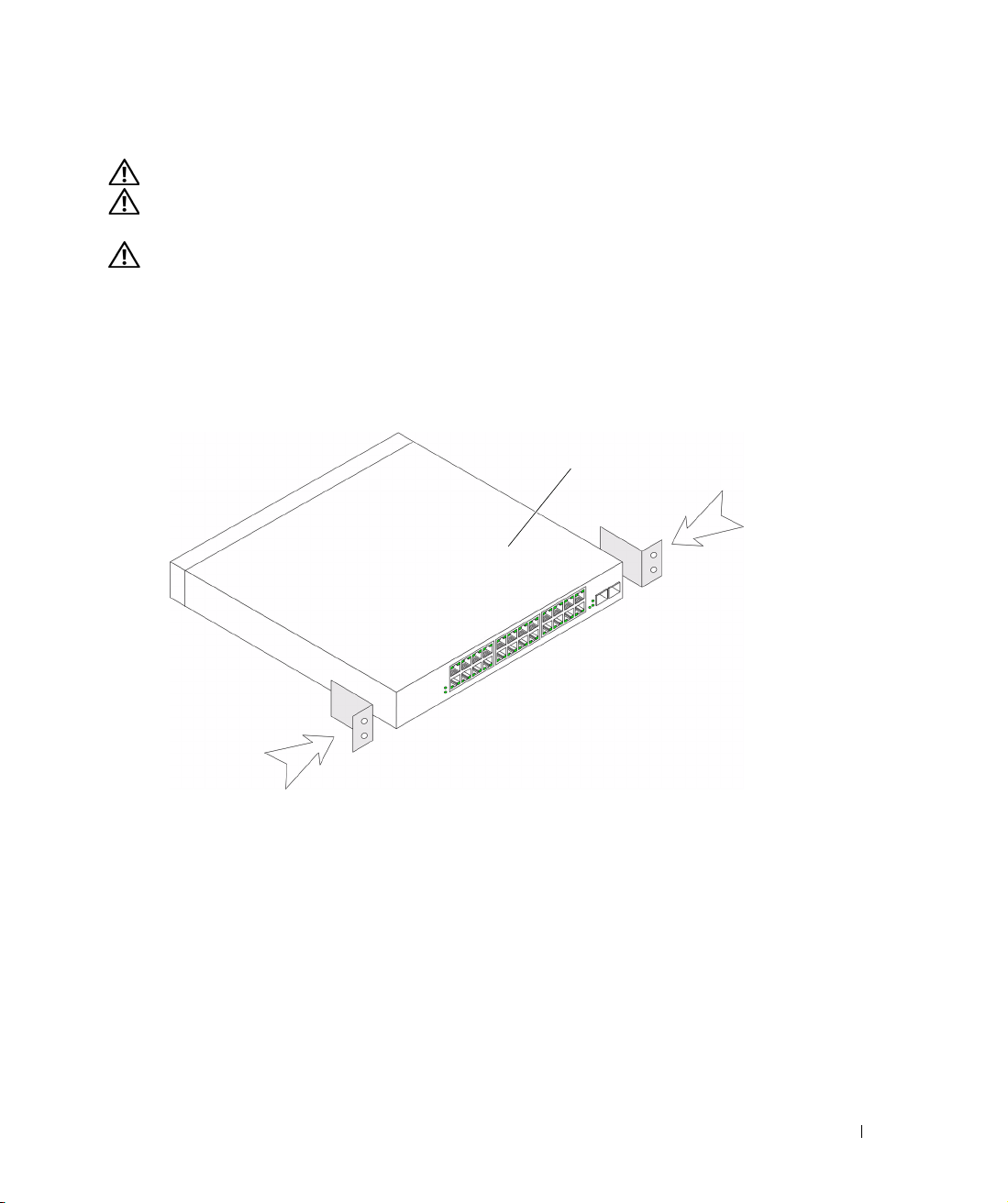
1
Place the supplied rack-mounting bracket on one side of the device, ensuring that the
mounting holes on the device line up to the mounting holes on the rack-mounting bracket.
The following figure illustrates where to mount the brackets.
Figure 1-1. Bracket Installation for Rack Mounting
PowerConnect Switch
2
Insert the supplied screws into the holes on the sides of the device and tighten with
a screwdriver.
3
Repeat the process for the rack-mounting bracket on the other side of the device.
4
Insert the unit into the 48.26-cm (19-inch) rack, ensuring that the rack-mounting holes
on the device line up to the mounting holes on the rack.
5
Secure the unit to the rack with the rack screws (not provided). Fasten the lower pair of screws
before the upper pair of screws. Ensure that the ventilation holes are not obstructed.
Getting Started Guide 7
Page 10
Installing on a Wall
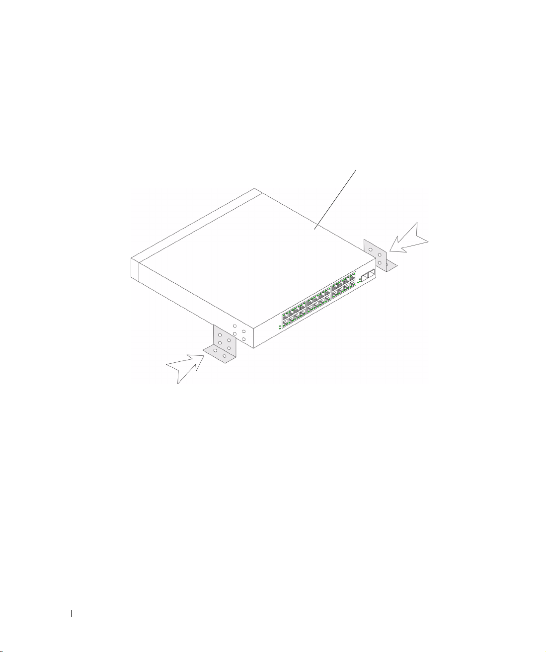
1
Place the supplied wall-mounting bracket on one side of the device, ensuring that the
mounting holes on the device line up to the mounting holes on the rack-mounting bracket.
The following figure illustrates where to mount the brackets.
Figure 1-2. Bracket Installation for Wall Mounting
PowerConnect Switch
2
Insert the supplied screws into the rack-mounting holes and tighten with a screwdriver.
3
Repeat the process for the wall-mounting bracket on the other side of the device.
4
Place the device against the wall and mark the wall through the bracket holes.
5
Drill holes in the wall for the brackets and install the appropriate mounting hardware
(not supplied).
6
Place the device against the wall so that the bracket holes align with the holes in the wall.
7
Insert and tighten the screws through each of the mounting brackets. Ensure that
the ventilation holes are not obstructed.
8 Getting Started Guide
Page 11
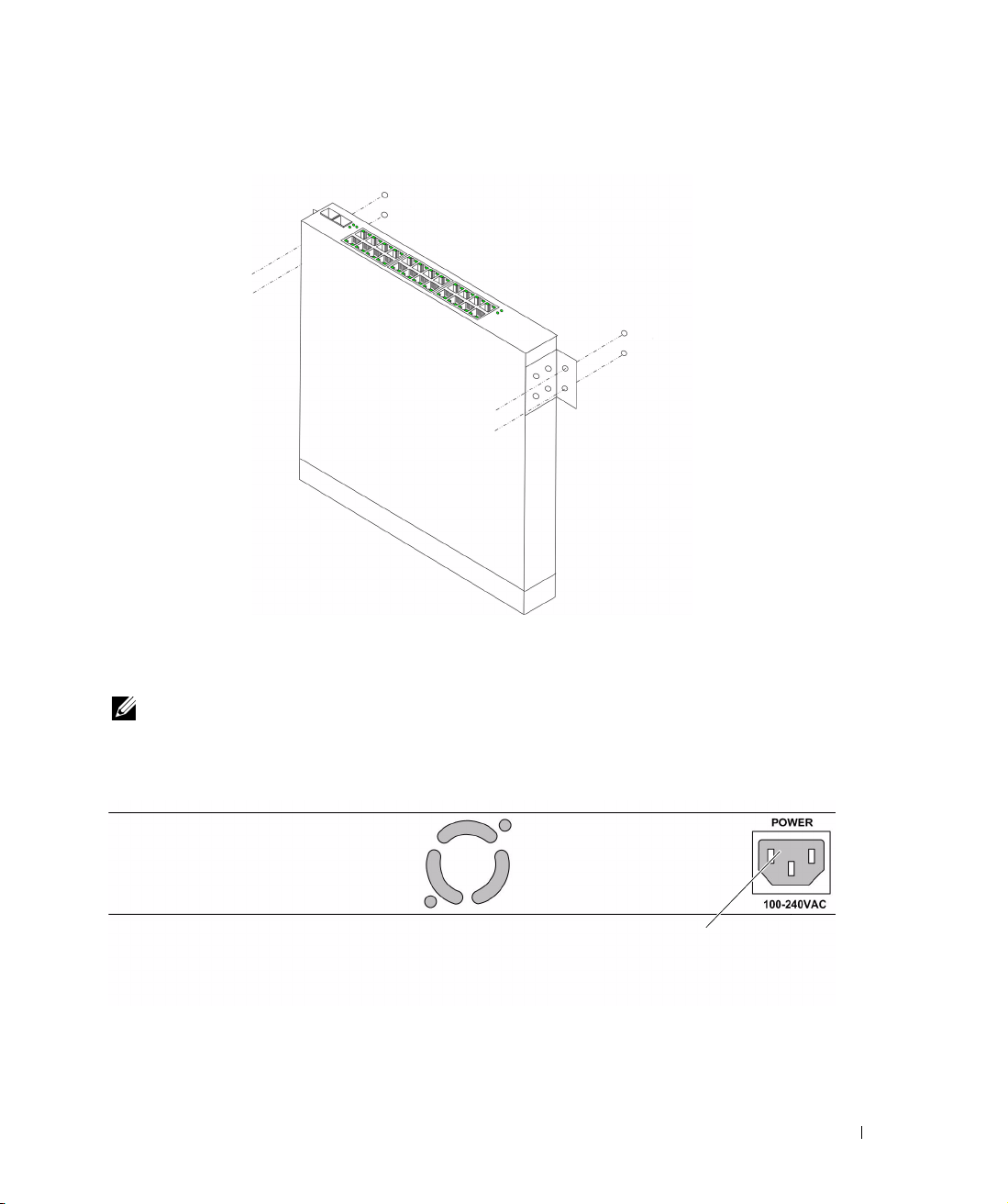
Figure 1-3. Mounting Device on Wall
Drilled Holes
Wall
Drilled Holes
Connecting a Device to a Power Supply
Connect the supplied AC power cable to the AC power connector on the back panel.
NOTE: Do not connect the power cable to a grounded AC outlet at this time. You will connect the device
to a power source in the steps detailed in Starting and Configuring the Device.
Figure 1-4. Back-Panel Power Connectors
Power Connector
PowerConnect Switch Rear View
Connect the device to an AC outlet. After you have connected the device to a power source,
confirm that the device is connected and operating correctly by examining the LEDs on
the front panel.
Getting Started Guide 9
Page 12

Starting and Configuring the Device
NOTE: The device is designed to function as an unmanaged switch without any configuration of the
management interface. Setup of the management interface is not a requirement if the switch is deployed
as an unmanaged switch. To use the management functions, refer the configuration options and details
in the User's Guide on the enclosed CD. Without specific configuration, the device functions with the
default settings, as described in the User's Guide.
NOTE: Before proceeding, read the release notes for this product. You can download the release notes
from the Dell Support website at support.dell.com.
NOTE: It is recommended that you obtain the most recent revision of the user documentation from
the Dell Support website at support.dell.com.
Booting the Switch
When the device is connected to a power source, the device LEDs glow indicating that power
is being supplied to the device. A power-on self-test (POST) runs every time the device is
initialized and checks hardware components to determine if the device is fully operational
before completely booting. If POST passes successfully, the System and the Power LEDs glow
and a valid executable image is loaded into RAM.
The boot process runs approximately 90 seconds.
Initial Configuration
NOTE: The initial configuration uses the following assumptions:
• The PowerConnect device is configured with the pre configured default IP (192.168.2.1) and subnet
mask (255.255.255.0).
• The PowerConnect device booted successfully.
To begin using the device, it is advisable to configure the device with the system specific
configuration.
NOTE: Obtain the following information from the network administrator before configuring the device:
• The IP address to be assigned to the VLAN 1 interface through which the device is to be managed
• The IP subnet mask for the network
• The default gateway (next hop router) IP address for configuring the default route.
10 Getting Started Guide
Page 13
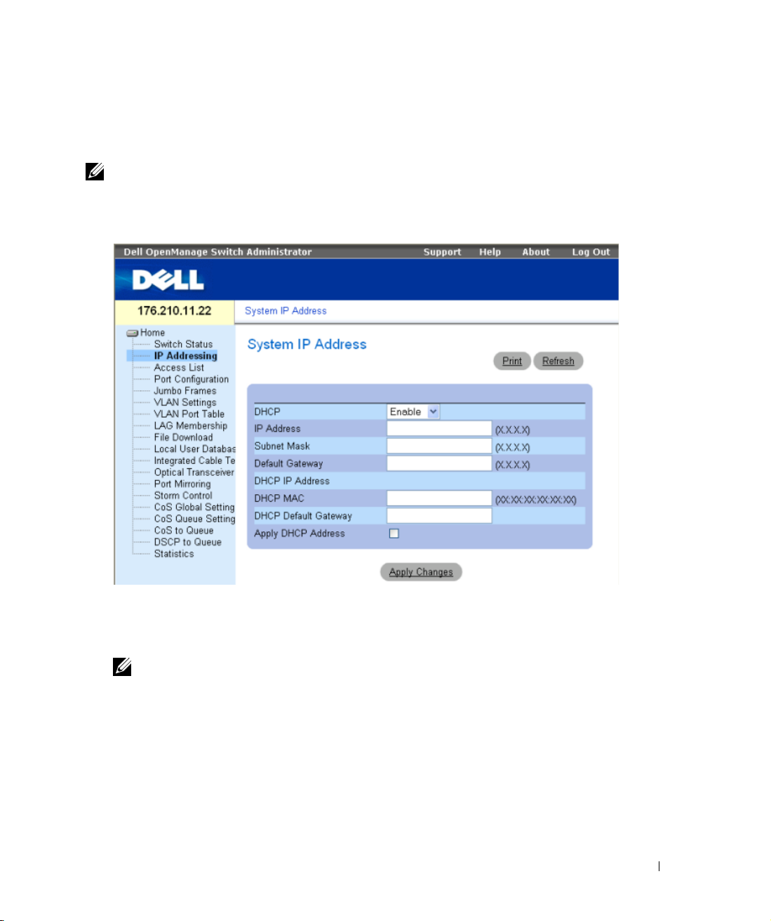
To configure the device:
1
Open the web management interface (from any desktop or workstation). To do so,
enter the IP address of the device in the URL field of a web browser.
NOTE: The web management interface supports the following web browsers:
Microsoft Internet Explorer 6.x or above and Mozilla Version 1.7.x or above.
2
In the Web user interface, Click
IP Addressing.
The
System IP Address
window appears.
3
Enter the IP Address, Subnet Mask and Default Gateway.
4
Click
Apply Changes
NOTE: This getting started guide provides information on the steps necessary for basic setup
of the switch. For more information on the management capabilities of the switch, please refer
the PowerConnect 27xx Series User's Guide found on your documenatation CD.
. The device is configured.
Getting Started Guide 11
Page 14

12 Getting Started Guide
Page 15

Systèmes Dell™ PowerConnect™ 27XX
Guide de mise en route
www.dell.com | support.dell.com
Page 16

Remarques, avis et précautions
REMARQUE : une REMARQUE indique des informations importantes qui peuvent vous aider à mieux utiliser
l'ordinateur.
AVIS : un AVIS vous avertit d'un dommage ou d'une perte de données potentiels et vous indique comment éviter
ce problème.
PRÉCAUTION : une PRÉCAUTION indique un risque potentiel d'endommagement du matériel, de blessure corporelle
ou de mort.
____________________
Les informations contenues dans ce document peuvent être modifiées sans préavis.
© 2004-2006 Dell Inc. Tous droits réservés.
La reproduction de ce document de quelque manière que ce soit sans l'autorisation écrite de Dell Inc. est strictement interdite.
Marques utilisées dans ce document : Dell, Dell OpenManage, PowerEdge, le logo DELL, Inspiron, Dell Precision, Dimension, OptiPlex,
PowerConnect, PowerApp, PowerVault, Axim, DellNet et Latitude sont des marques de Dell Inc. ; Microsoft et Windows sont des marques
déposées de Microsoft Corporation.
Tous les autres noms de marques et marques commerciales utilisés dans ce document se rapportent aux sociétés propriétaires des marques et
des noms de ces produits. Dell Inc. décline tout intérêt dans l'utilisation des marques déposées et des noms de marques ne lui appartenant pas.
Modèles : PC2708, PC2716, PC2724 et PC2748
Novembre 2006 P/N T9020 Rev. A02
Page 17

Sommaire
Installation . . . . . . . . . . . . . . . . . . . . . . . . . . . . . . . . . . 17
Présentation générale . . . . . . . . . . . . . . . . . . . . . . . . . . . . . . . . . . . . . . . . . . . . . . 17
Préparation du site . . . . . . . . . . . . . . . . . . . . . . . . . . . . . . . . . . . . . . . . . . . . . . . . . 17
Déballage . . . . . . . . . . . . . . . . . . . . . . . . . . . . . . . . . . . . . . . . . . . . . . . . . . . . . . . . . 17
Montage de l'unité . . . . . . . . . . . . . . . . . . . . . . . . . . . . . . . . . . . . . . . . . . . . . . . . . 18
Démarrage et configuration de l'unité
Démarrage du commutateur . . . . . . . . . . . . . . . . . . . . . . . . . . . . . . . . . . . . . . . . . 22
Configuration initiale . . . . . . . . . . . . . . . . . . . . . . . . . . . . . . . . . . . . . . . . . . . . . . . . 22
. . . . . . . . . . . . . . . . . . . . . 22
Sommaire 15
Page 18

16 Sommaire
Page 19

Installation
Présentation générale
Ce document contient des informations de base sur l'installation et la première utilisation des
systèmes PowerConnect 27xx. Pour obtenir des informations plus détaillées, consultez le
d'utilisation Dell™ PowerConnect™ 27xx
Vous pouvez également vous rendre sur le site
des informations les plus récentes concernant la documentation et les applications.
, que vous trouverez sur le CD de documentation.
support.dell.com
pour prendre connaissance
Préparation du site
Les unités Dell PowerConnect 27xx peuvent être montées dans un rack standard de 19 pouces
(48,26 cm), posées sur une table ou fixées à un mur. Avant d'installer l'unité, vérifiez que l'emplacement choisi pour l'installation satisfait aux conditions suivantes :
•
Alimentation :
à 50-60 Hz, facilement accessible. Vérifiez que le voyant d'alimentation est visible une fois
tous les branchements effectués.
Dégagement :
•
opérateur. Prévoyez un dégagement pour le câblage, les connexions électriques et la ventilation.
•
Câblage :
telles que les émetteurs radioélectriques, les amplificateurs de diffusion, les lignes électriques
et les luminaires pour lampes fluorescentes.
•
Conditions ambiantes :
(32 et 113º F) avec une humidité relative maximale de 95 % sans condensation.
l'unité doit être installée à proximité d'une prise électrique de 100-240 V c.a.
l'avant de l'unité doit être suffisamment dégagé pour rester accessible à un
les câbles doivent être acheminés de façon à éviter les sources de bruit électrique,
la température ambiante doit être comprise entre 0 et 45º C
Guide
Déballage
Contenu du carton
Lors du déballage de l'unité, vérifiez que le carton contient les éléments suivants :
• Unité/Commutateur
• Cordon d'alimentation en CA
• Patins adhésifs en caoutchouc
• Kit de montage pour l'installation en rack ou kit de fixation murale
• CD de documentation
• Guide d'information sur le produit
Guide de mise en route 17
Page 20

Déballage de l'unité
REMARQUE : avant de déballer l'unité, examinez le carton d'emballage et signalez immédiatement
tout dommage apparent.
Placez la boîte sur une surface propre et stable.
1
2
Ouvrez-la ou retirez sa partie supérieure.
3
Avec précaution, retirez l'unité de sa boîte et posez-la sur une surface propre et stable.
4
Retirez tout le matériel d'emballage.
5
Vérifiez que l'unité et ses accessoires ne sont pas endommagés. Signalez immédiatement
tout dommage constaté.
Montage de l'unité
Les instructions de montage ci-après s'appliquent aux unités PowerConnect 27xx.
Il existe trois options possibles pour le montage :
• Installation sur une surface plane
• Montage en rack
• Fixation murale
Installation sur une surface plane
L'unité doit être installée sur une surface plane si elle n'est pas installée dans un rack ou sur un mur.
Cette surface doit pouvoir supporter le poids de l'unité et de ses câbles.
1
Fixez les patins adhésifs en caoutchouc sur les emplacements indiqués en dessous du châssis.
2
Posez l'unité sur une surface plane en laissant un espace de 5 cm (2 pouces) de chaque côté et
de 13 cm (5 pouces) à l'arrière.
3
Assurez-vous que l'unité est suffisamment ventilée.
18 Guide de mise en route
Page 21

Montage en rack
PRÉCAUTION : déconnectez tous les câbles avant de monter l'unité dans un rack ou une armoire.
PRÉCAUTION : prenez connaissance des consignes de sécurité se trouvant dans le Guide
d'information sur le produit ou concernant toute autre unité en contact avec le commutateur.
PRÉCAUTION : si vous installez plusieurs unités dans un rack, commencez par les emplacements
du bas et procédez en remontant vers le haut du rack.
Placez le support de fixation du rack sur un côté de l'unité, en alignant les orifices de montage
1
des deux éléments.
L'illustration suivante indique l'emplacement où les supports doivent être placés.
Figure 1-1. Installation des supports pour un montage en rack
Commutateur PowerConnect
2
Insérez les vis fournies dans les orifices situés sur les côtés de l'unité, puis serrez-les à l'aide
d'un tournevis.
3
Répétez l'opération de l'autre côté de l'unité.
4
Insérez l'unité dans le rack, en veillant à ce que les orifices de montage de l'unité soient bien
alignés sur ceux du rack.
5
Fixez ensuite l'unité sur le rack à l'aide des vis appropriées (non fournies). Vous devez fixer
les deux vis du bas avant celles du haut. Vérifiez que les orifices de ventilation ne sont pas
obstrués.
Guide de mise en route 19
Page 22

Fixation murale
1
Placez le support de fixation murale sur un côté de l'unité, en alignant les orifices de montage
des deux éléments.
L'illustration suivante indique l'emplacement où les supports doivent être placés.
Figure 1-2. Installation des supports pour une fixation murale
Commutateur PowerConnect
2
Insérez les vis fournies dans les orifices et serrez-les à l'aide d'un tournevis.
3
Répétez l'opération de l'autre côté de l'unité.
4
Placez l'unité contre le mur et faites des repères en passant un feutre dans les orifices
du support de montage.
5
Percez le mur aux endroits marqués et installez le matériel de montage approprié
(non fourni).
6
Placez l'unité contre le mur en alignant les trous du support sur ceux que vous avez percés
dans le mur.
7
Insérez les vis dans chaque support de montage et serrez-les. Vérifiez que les orifices
de ventilation ne sont pas obstrués.
20 Guide de mise en route
Page 23

Figure 1-3. Fixation murale de l'unité
Trous percés
Mur
Trous percés
Connexion de l'unité à un bloc d'alimentation
Connectez le cordon d'alimentation en CA sur le connecteur d'alimentation situé sur le panneau
arrière de l'unité.
REMARQUE : à ce stade, vous ne devez pas encore brancher le cordon d'alimentation sur une prise
reliée à la terre. Vous effectuerez ce branchement lorsque vous parviendrez à la section Démarrage et
configuration de l'unité.
Figure 1-4. Connecteurs d'alimentation du panneau arrière
Connecteur d'alimentation
Vue arrière du PowerConnect
Branchez l'unité sur une prise électrique. Une fois ce branchement effectué, vérifiez que l'unité
fonctionne correctement en examinant les voyants situés sur le panneau avant.
Guide de mise en route 21
Page 24

Démarrage et configuration de l'unité
REMARQUE : l'unité est conçue pour fonctionner sans gestion particulière et sans configuration de
l'interface de gestion. La configuration de cette interface n'est en effet pas nécessaire si le commutateur
est déployé sans être géré. Pour utiliser les fonctions de gestion, consultez les sections relatives aux
options de configuration dans le Guide d'utilisation qui vous a été fourni sur CD. Lorsqu'elle n'est pas
configurée, l'unité fonctionne avec les paramètres par défaut décrits dans le Guide d'utilisation.
REMARQUE : avant de continuer, lisez les notes d'édition concernant ce produit. Vous pouvez
les télécharger à partir du site d'assistance technique de Dell, support.dell.com.
REMARQUE : nous vous recommandons de vous procurer la version la plus récente de la documen-
tation, disponible sur le site support.dell.com.
Démarrage du commutateur
Lorsque l'unité est branchée sur une source d'alimentation, les voyants s'allument pour indiquer
que l'appareil est sous tension. Un auto-test de démarrage (POST) s'exécute à chaque initialisation
de l'unité ; il passe les composants en revue pour vérifier que l'unité est opérationnelle avant que le
démarrage ne soit totalement effectif. Si ce test se déroule sans incident, les voyants s'allument et
une image exécutable valide est chargée dans la mémoire vive.
Le processus de démarrage dure environ 90 secondes.
Configuration initiale
REMARQUE : la configuration initiale est basée sur les hypothèses suivantes :
• Le PowerConnect utilise l'IP par défaut 192.168.2.1 et le masque de sous-réseau par défaut
255.255.255.0.
• Le PowerConnect a démarré correctement.
Pour commencer à utiliser l'unité, il est préférable de la configurer en fonction des paramètres
spécifiques du système.
REMARQUE : demandez les informations suivantes à votre administrateur réseau avant de configurer
l'unité :
• Adresse IP à attribuer à l'interface VLAN 1 utilisée pour la gestion de l'unité
• Masque de sous-réseau IP
• Adresse IP de la passerelle par défaut (routeur suivant) permettant de configurer la route par défaut
22 Guide de mise en route
Page 25

Pour configurer l'unité :
1
Ouvrez l'interface de gestion Web (à partir de toute station de travail). Pour ce faire,
entrez l'adresse IP de l'unité dans la zone d'adresse d'un navigateur Web.
REMARQUE : l'interface de gestion Web prend en charge les navigateurs suivants :
Microsoft Internet Explorer 6.x ou suivante et Mozilla version 1.7.x ou suivante.
Dans l'interface utilisateur Web, cliquez sur
2
La fenêtre
System IP Address
(Adresse IP du système) s'affiche.
IP Addressing
(Adressage IP).
3
Entrez l'adresse IP, le masque de sous-réseau et la passerelle par défaut.
4
Cliquez sur
REMARQUE : le présent guide contient uniquement les instructions nécessaires à la configuration
Apply Changes
de base du commutateur. Pour plus de détails concernant les options de gestion disponibles,
consultez le Guide d'utilisation PowerConnect 27xx fourni sur le CD de documentation.
(Appliquer les modifications). L'unité est configurée.
Guide de mise en route 23
Page 26

24 Guide de mise en route
Page 27

Sistemas Dell™ PowerConnect™ 27XX
Guia de inicialização
www.dell.com | support.dell.com
Page 28

Observações, avisos e cuidados
OBSERVAÇÃO: As OBSERVAÇÕES fornecem informações importantes que o ajudam a usar melhor o dispositivo.
AVISO: As mensagens de AVISO informam sobre danos potenciais ao hardware ou perda de dados e indicam
como evitar o problema.
CUIDADO: As mensagens de CUIDADO indicam possíveis danos à propriedade, lesões pessoais ou morte.
____________________
As informações contidas neste documento estão sujeitas a alterações sem aviso prévio.
© 2004-2006 Dell Inc. Todos os direitos reservados.
Fica proibida a reprodução por quaisquer meios sem a permissão por escrito da Dell Inc.
Marcas comerciais mencionadas neste texto: Dell, Dell OpenManage, PowerEdge, o logotipo da DELL, Inspiron, Dell Precision, Dimension,
OptiPlex, PowerConnect, PowerApp, PowerVault, Axim, DellNet e Latitude são marcas comerciais da Dell Inc. Microsoft e Windows são
marcas registradas da Microsoft Corporation.
Outras marcas e nomes comerciais podem ser utilizados neste documento para fazer referência às entidades proprietárias das marcas e nomes
ou seus produtos. A Dell Inc. renuncia qualquer interesse proprietário em marcas e nomes comerciais que não sejam de sua propriedade.
Modelos: PC2708, PC2716, PC2724 e PC2748
Nevembro de 2006 P/N T9020 Rev. A02
Page 29

Conteúdo
Instalação. . . . . . . . . . . . . . . . . . . . . . . . . . . . . . . . . . . 29
Visão geral . . . . . . . . . . . . . . . . . . . . . . . . . . . . . . . . . . . . . . . . . . . . . . . . . . . . . . . . 29
Preparação do local . . . . . . . . . . . . . . . . . . . . . . . . . . . . . . . . . . . . . . . . . . . . . . . . 29
Remoção da embalagem . . . . . . . . . . . . . . . . . . . . . . . . . . . . . . . . . . . . . . . . . . . . 29
Montagem do dispositivo . . . . . . . . . . . . . . . . . . . . . . . . . . . . . . . . . . . . . . . . . . . . 30
Inicialização e configuração do dispositivo
Inicialização do comutador . . . . . . . . . . . . . . . . . . . . . . . . . . . . . . . . . . . . . . . . . . 34
Configuração inicial . . . . . . . . . . . . . . . . . . . . . . . . . . . . . . . . . . . . . . . . . . . . . . . . 34
. . . . . . . . . . . . . . . . . . 34
Conteúdo 27
Page 30

28 Conteúdo
Page 31

Instalação
Visão geral
Este documento fornece informações básicas sobre a instalação e utilização do sistema
PowerConnect da série 27xx. Para obter mais informações, consulte o
PowerConnect™ da série 27xx
Dell no endereço
esoftware.
support.dell.com
, disponível no CD de documentação, ou visite o site de suporte da
para obter as atualizações mais recentes em documentação
Preparação do local
Os dispositivos PowerConnect da série 27xx podem ser montados em um rack padrão de 48,26 cm,
sobre um tampo de mesa ou na parede. Antes de instalar a unidade, verifique se o local escolhido
para a instalação está de acordo com os seguintes requisitos:
•
Fornecimento de energia
VCA, 50-60 Hz, de fácil acesso. Verifique se após a conexão, o LED de ligação no dispositivo
está visível.
•
Espaço
– verifique se o espaço próximo ao painel frontal é adequado para que o operador possa
ter acesso ao equipamento. Reserve um espaço livre para cabos, conexões de energia e
ventilação.
•
Cabeamento
como transmissores de rádio, amplificadores de difusão, linhas de força e instalações com
iluminação fluorescente.
•
Requisitos ambientais
variar de 0 a 45 ºC com umidade relativa de até 95%, sem condensação.
– o cabeamento deve ser guiado de forma a evitar fontes de ruídos elétricos,
– a unidade deve ser instalada próxima a uma tomada de 100-240
– a temperatura de funcionamento da unidade no ambiente deve
Guia do usuário do Dell™
Remoção da embalagem
Conteúdo da embalagem
Quando for retirar o dispositivo da embalagem, certifique-se de que os seguintes itens foram
fornecidos:
• Dispositivo/comutador
• Cabo de alimentação CA
• Suportes de borracha auto-adesivos
• Kit de montagem para a instalação no rack ou na parede
• CD de documentação
• Guia de informações do produto
Guia de inicialização 29
Page 32

Remoção do dispositivo da embalagem
OBSERVAÇÃO: Examine a embalagem antes de retirar o dispositivo. Informe imediatamente o fabricante
caso observe sinais de danos.
Coloque a caixa sobre uma superfície plana e limpa.
1
2
Abra a caixa ou remova a parte superior da mesma.
3
Retire cuidadosamente o dispositivo da caixa e coloque-o em uma superfície limpa e segura.
4
Retire todo o material de embalagem.
5
Verifique se há danos no dispositivo e nos acessórios. Em caso positivo, informe
imediatamente o fabricante.
Montagem do dispositivo
As seguintes instruções de montagem aplicam-se aos dispositivos PowerConnect da série 27xx.
Há três opções de montagem do dispositivo:
• Instalação em superfície plana
• Instalação em rack
• Instalação em parede
Instalação em superfície plana
O dispositivo deve ser instalado sobre uma superfície plana caso não seja instalado em um rack
ou em uma parede. A superfície deve suportar o peso do dispositivo e de seus cabos.
1
Fixe os suportes de borracha auto-adesivos nos locais marcados localizados na parte inferior
do chassi.
2
Coloque o dispositivo em uma superfície plana, deixando um espaço livre de 5,08 cm nas
laterais e 12,7 cm na parte posterior.
3
Certifique-se de que o dispositivo tenha ventilação adequada.
30 Guia de inicialização
Page 33

Instalação em rack
CUIDADO: Desconecte todos os cabos da unidade antes de montar o dispositivo em um rack
ou gabinete.
CUIDADO: Leia as informações de segurança no Guia de informações do produto bem como as
informações de segurança para outros dispositivos que serão conectados ou darão suporte ao
comutador.
CUIDADO: Quando montar vários dispositivos em um rack, faça-o de baixo para cima.
Coloque o suporte para montagem em rack fornecido em um lado do dispositivo,
1
certificando-se de que os orifícios de montagem do dispositivo estejam alinhados com
os orifícios de montagem do suporte.
A seguinte figura ilustra onde montar os suportes.
Figura 1-1. Instalação de suportes para montagem em rack
Comutador PowerConnect
2
Insira os parafusos fornecidos nos orifícios das laterais do dispositivo e aparafuse com
uma chave-de-fenda.
3
Repita o processo para instalar o suporte de montagem em rack no outro lado do dispositivo.
4
Insira a unidade no rack de 48,26 cm, certificando-se de que os orifícios de montagem do
dispositivo estejam alinhados com os orifícios de montagem do rack.
5
Fixe a unidade no rack com os parafusos correspondentes (não fornecidos). Aperte o par
de parafusos da parte inferior antes de apertar os parafusos da parte superior. Verifique se
os orifícios de ventilação não estão obstruídos.
Guia de inicialização 31
Page 34

Instalação em parede
1
Coloque o suporte para montagem em parede fornecido em um lado do dispositivo,
certificando-se de que os orifícios de montagem do dispositivo estejam alinhados
com os orifícios de montagem do suporte.
A seguinte figura ilustra onde montar os suportes.
Figura 1-2. Instalação de suportes para montagem em parede
Comutador PowerConnect
2
Insira os parafusos fornecidos nos orifícios de montagem do rack e aperte-os com uma chave
de fenda.
3
Repita o processo para instalar o suporte de montagem em parede no outro lado do
dispositivo.
4
Apóie o dispositivo na parede e marque-a através dos orifícios dos suportes.
5
Perfure a parede para os suportes e instale o hardware de montagem adequado
(não fornecido).
6
Apóie o dispositivo na parede de forma que os orifícios dos suportes fiquem alinhados com
os orifícios na parede.
7
Insira e aperte os parafusos através de cada suporte de montagem. Verifique se os orifícios
de ventilação não estão obstruídos.
32 Guia de inicialização
Page 35

Figura 1-3. Montagem do dispositivo na parede
Orifícios perfurados
Parede
Orifícios perfurados
Conexão de dispositivos às fontes de alimentação
Conecte o cabo de alimentação CA fornecido ao conector de alimentação CA no painel posterior.
OBSERVAÇÃO: Não conecte o cabo de alimentação a uma tomada CA aterrada neste momento.
Conecte o dispositivo a uma fonte de alimentação de acordo com as etapas detalhadas na seção
Inicialização e configuração do dispositivo.
Figura 1-4. Conectores de energia do painel posterior
Conector de energia
Visão posterior do comutador PowerConnect
Conecte o dispositivo a uma tomada CA. Depois de ter conectado o dispositivo a uma fonte de
alimentação, confirme se o dispositivo está conectado e funcionando corretamente analisando
os LEDs do painel frontal.
Guia de inicialização 33
Page 36

Inicialização e configuração do dispositivo
OBSERVAÇÃO: O dispositivo foi projetado para funcionar como um comutador não gerenciado, sem
nenhuma configuração da interface de gerenciamento. A configuração da interface de gerenciamento
não é uma exigência se o comutador está instalado como um comutador não gerenciado. Para utilizar as
funções de gerenciamento, consulte as opções e os detalhes de configuração no Guia do usuário no CD
fornecido. Sem configuração específica, o dispositivo funciona com as definições padrão, como descrito
no Guia do usuário.
OBSERVAÇÃO: Antes de continuar, leia as notas de versão do produto. Você pode transferir as notas
de versão do site de suporte da Dell no endereço support.dell.com.
OBSERVAÇÃO: Recomendamos que obtenha a versão mais recente da documentação do usuário
no site de suporte da Dell, no endereço support.dell.com.
Inicialização do comutador
Quando o dispositivo está conectado a uma fonte de alimentação, os LEDs se acendem indicando
que a energia está sendo fornecida ao dispositivo. O teste automático de inicialização (POST) é
executado toda vez que o dispositivo é inicializado, e examina os componentes de hardware para
determinar se o dispositivo está funcionando corretamente antes da inicialização ser concluída.
Se o dispositivo passar no POST, os LEDs de sistema e de energia se acenderão e uma imagem
executável válida será carregada na RAM.
O processo de inicialização demora aproximadamente 90 segundos.
Configuração inicial
OBSERVAÇÃO: A configuração inicial considera o seguinte:
• O dispositivo PowerConnect está configurado com IP (192.168.2.1) e máscara de sub-rede
(255.255.255.0) padrão.
• O dispositivo PowerConnect inicializou corretamente.
Para começar a utilizar o dispositivo, configure-o utilizando os parâmetros específicos do sistema.
OBSERVAÇÃO: Obtenha as seguintes informações do administrador da rede antes de configurar
o dispositivo:
• O endereço IP a ser atribuído à interface VLAN 1 através do qual o dispositivo será gerenciado.
• A máscara de sub-rede do IP da rede.
• O endereço IP do gateway padrão (próximo salto de roteamento) para configurar o roteamento
padrão.
34 Guia de inicialização
Page 37

Para configurar o dispositivo:
1
Abra a interface de gerenciamento da web (de qualquer estação de trabalho ou computador
de mesa). Para isso, insira o endereço IP do dispositivo no campo de URL de um navegador
da Web.
OBSERVAÇÃO: A interface de gerenciamento da web é compatível com os seguintes navegadores:
Microsoft Internet Explorer 6.x ou posterior e Mozilla Versão 1.7.x ou posterior.
Na interface de usuário da web, clique em
2
A janela
System IP Address
(Endereço IP do sistema) é apresentada.
IP Addressing
(Endereçamento IP)
.
3
Insira o endereço IP, a máscara de sub-rede e o gateway padrão.
4
Clique em
OBSERVAÇÃO: Este guia de inicialização fornece informações sobre as etapas necessárias
Apply Changes
para a configuração básica do comutador. Para obter mais informações sobre os recursos
de gerenciamento do comutador, consulte o Guia do usuário do PowerConnect da série 27xx
encontrado no CD de documentação.
(Aplicar alterações). O dispositivo está configurado.
Guia de inicialização 35
Page 38

36 Guia de inicialização
Page 39

Sistemas Dell™ PowerConnect™ 27XX
Guía de introducción
www.dell.com | support.dell.com
Page 40

Notas, avisos y precauciones
NOTA: una NOTA indica información importante que le ayudará a usar mejor su dispositivo.
AVISO: un AVISO indica la posibilidad de daños en el hardware o la pérdida de datos, e informa de cómo evitar
el problema.
PRECAUCIÓN: un mensaje de PRECAUCIÓN indica el riesgo de daños materiales, lesiones corporales o incluso
la muerte.
____________________
La información contenida en este documento puede modificarse sin previo aviso.
© 2004-2006 Dell Inc. Reservados todos los derechos.
Queda estrictamente prohibida la reproducción de este documento en cualquier forma sin la autorización por escrito de Dell Inc.
Marcas comerciales utilizadas en este texto: Dell, Dell OpenManage, PowerEdge, el logotipo de DELL, Inspiron, Dell Precision, Dimension,
OptiPlex, PowerConnect, PowerApp, PowerVault, Axim, DellNet y Latitude son marcas comerciales de Dell Inc. Microsoft y Windows son
marcas comerciales registradas de Microsoft Corporation.
Otras marcas y otros nombres comerciales pueden utilizarse en este documento para hacer referencia a las entidades que los poseen
o a sus productos. Dell Inc. renuncia a cualquier interés sobre la propiedad de marcas y nombres comerciales que no sean los suyos.
Modelos: PC2708, PC2716, PC2724 y PC2748
Noviembre de 2006 P/N T9020 Rev. A02
Page 41

Contenido
Instalación . . . . . . . . . . . . . . . . . . . . . . . . . . . . . . . . . . 41
Información general . . . . . . . . . . . . . . . . . . . . . . . . . . . . . . . . . . . . . . . . . . . . . . . . 41
Preparación del sitio . . . . . . . . . . . . . . . . . . . . . . . . . . . . . . . . . . . . . . . . . . . . . . . . 41
Desembalaje . . . . . . . . . . . . . . . . . . . . . . . . . . . . . . . . . . . . . . . . . . . . . . . . . . . . . . . 41
Montaje del dispositivo . . . . . . . . . . . . . . . . . . . . . . . . . . . . . . . . . . . . . . . . . . . . . . 42
Inicio y configuración del dispositivo
Inicio del conmutador . . . . . . . . . . . . . . . . . . . . . . . . . . . . . . . . . . . . . . . . . . . . . . . 46
Configuración inicial . . . . . . . . . . . . . . . . . . . . . . . . . . . . . . . . . . . . . . . . . . . . . . . . 46
. . . . . . . . . . . . . . . . . . . . . 46
Contenido 39
Page 42

40 Contenido
Page 43

Instalación
Información general
En este documento se proporciona información básica para instalar e iniciar el sistema PowerConnect
serie 27xx. Para obtener más información, consulte la publicación
Series User's Guide
documentación, o consulte la página Web de asistencia de Dell (
las últimas actualizaciones de la documentación y del software.
(Guía del usuario de Dell™ PowerConnect™ serie 27xx), incluida en el CD de
Preparación del sitio
Los dispositivos PowerConnect de la serie 27xx se pueden montar en un rack estándar de 48,26 cm,
colocar sobre un escritorio o montar en una pared. Antes de instalar la unidad, verifique que la
ubicación elegida cumpla los requisitos siguientes:
•
Alimentación:
la que se accede fácilmente. Asegúrese de que después de la conexión el LED de alimentación
del dispositivo quede visible.
•
Espacio libre:
trabajar con comodidad. Deje espacio libre para el cableado, las conexiones de alimentación
y la ventilación.
•
Cableado:
radiotransmisores, amplificadores de transmisión, líneas de alimentación e instalaciones
fijas de luz fluorescente.
•
Requisitos ambientales:
de la unidad es de 0 a 45 °C a una humedad relativa máxima del 95 %, sin condensación.
la unidad se instala cerca de una toma eléctrica de 100-240 V CA y 50-60 Hz a
debe haber un espacio libre delante del equipo para que el operador pueda
el cableado está canalizado para evitar fuentes de ruido eléctrico, como
el intervalo de temperatura ambiental de funcionamiento
Dell™ PowerConnect™ 27xx
support.dell.com
) para conseguir
Desembalaje
Contenido del paquete
Cuando desembale el dispositivo, asegúrese de que se incluyen los elementos siguientes:
• Dispositivo/conmutador
• Cable de alimentación de CA
• Almohadillas de goma autoadhesivas
• Kit de montaje para la instalación en rack o en pared
• CD de documentación
• Guía de información del producto
Guía de introducción 41
Page 44

Desembalaje del dispositivo
NOTA: antes de desembalar el dispositivo, examine el paquete e informe inmediatamente de cualquier
daño.
Coloque la caja en una superficie plana y limpia.
1
2
Abra la caja o extraiga la parte superior de ésta.
3
Extraiga con precaución el dispositivo de la caja y colóquelo en una superficie estable
y limpia.
4
Extraiga todo el material de embalaje.
5
Compruebe que el dispositivo y los accesorios no estén dañados. Informe inmediatamente
de cualquier daño.
Montaje del dispositivo
Las instrucciones de montaje siguientes corresponden a los dispositivos PowerConnect
de la serie 27xx. Existen tres opciones de montaje del dispositivo:
• Instalación en una superficie plana
• Instalación en un rack
• Instalación en una pared
Instalación en una superficie plana
Si no se instala en un rack ni en una pared, el dispositivo debe instalarse en una superficie plana.
La superficie debe soportar el peso del dispositivo y de los cables.
1
Fije las almohadillas de goma autoadhesivas en cada zona marcada de la parte inferior
del chasis.
2
Coloque el dispositivo en una superficie plana y deje 5,08 cm de separación a cada lado
y 12,7 cm en la parte posterior.
3
Asegúrese de que el dispositivo dispone de la ventilación correcta.
42 Guía de introducción
Page 45

Instalación en un rack
PRECAUCIÓN: desconecte todos los cables de la unidad antes de montar el dispositivo en un rack
o armario.
PRECAUCIÓN: lea la información de seguridad incluida en la Guía de información del producto y la
información de seguridad de los otros dispositivos que están conectados o asociados al conmutador.
PRECAUCIÓN: cuando monte varios dispositivos en un rack, móntelos empezando por abajo.
Coloque el soporte de montaje en rack suministrado en un lateral del dispositivo y asegúrese
1
de que los orificios de montaje del dispositivo coinciden con los orificios de montaje del
soporte de montaje en rack.
En la figura siguiente se muestra dónde deben montarse los soportes.
Figura 1-1. Instalación de los soportes para el montaje en rack
Conmutador PowerConnect
2
Inserte los tornillos suministrados en los orificios de los laterales del dispositivo y apriételos
con un destornillador.
3
Repita el proceso para el soporte de montaje en rack en el otro lado del dispositivo.
4
Inserte la unidad en el rack de 48,26 cm y asegúrese de que los orificios de montaje en rack
del dispositivo coinciden con los orificios de montaje del rack.
5
Fije la unidad al rack con los tornillos de rack (no incluidos). Apriete primero el par inferior
de tornillos y después el superior. Asegúrese de que los orificios de ventilación no están
obstruidos.
Guía de introducción 43
Page 46

Instalación en una pared
1
Coloque el soporte de montaje en pared suministrado en un lateral del dispositivo y asegúrese
de que los orificios de montaje del dispositivo coinciden con los orificios de montaje del
soporte de montaje en rack.
En la figura siguiente se muestra dónde deben montarse los soportes.
Figura 1-2. Instalación de los soportes para el montaje en pared
Conmutador PowerConnect
2
Inserte los tornillos suministrados en los orificios de montaje en rack y apriételos con
un destornillador.
3
Repita el proceso para el soporte de montaje en pared en el otro lado del dispositivo.
4
Coloque el dispositivo contra la pared y realice unas marcas en la misma a través de los
orificios de los soportes.
5
Taladre en la pared agujeros para los soportes e instale los accesorios de montaje necesarios
(no incluidos).
6
Coloque el dispositivo contra la pared de modo que los orificios de los soportes queden
alineados con los agujeros de la pared.
7
Inserte y apriete los tornillos en cada uno de los soportes de montaje. Asegúrese de que
los orificios de ventilación no están obstruidos.
44 Guía de introducción
Page 47

Figura 1-3. Montaje del dispositivo en la pared
Agujeros taladrados
Pared
Agujeros taladrados
Conexión de un dispositivo a una fuente de alimentación
Conecte el cable de alimentación de CA suministrado al conector de alimentación de CA del panel
posterior.
NOTA: no conecte el cable de alimentación a una toma eléctrica de CA con conexión a tierra en este
momento. Debe conectar el dispositivo a una fuente de alimentación siguiendo los pasos que se detallan
en la sección Inicio y configuración del dispositivo.
Figura 1-4. Conectores de alimentación del panel posterior
Vista posterior del conmutador PowerConnect
Conector de alimentación
Conecte el dispositivo a una toma eléctrica de CA. Después de conectar el dispositivo a una fuente de
alimentación, compruebe que éste está conectado y funciona correctamente examinando los LED
del panel frontal.
Guía de introducción 45
Page 48

Inicio y configuración del dispositivo
NOTA: este dispositivo está diseñado para funcionar como un conmutador no administrado sin ninguna
configuración de la interfaz de administración. Si el conmutador se utiliza como un conmutador no
administrado, no es necesario configurar la interfaz de administración. Para hacer uso de las funciones
de administración, consulte las opciones y la información de configuración que se incluyen en la Guía
del usuario del CD adjunto. Sin una configuración específica, el dispositivo funciona con los valores
predeterminados, tal como se describe en la guía del usuario.
NOTA: antes de continuar, lea las notas de la versión de este producto. Puede descargar las notas
de la versión de la página Web de asistencia de Dell (support.dell.com).
NOTA: se recomienda descargar la revisión más reciente de la documentación del usuario que
encontrará en la página Web de asistencia de Dell (support.dell.com).
Inicio del conmutador
Cuando se conecta el dispositivo a una fuente de energía, los LED del dispositivo se encienden
para indicar que éste recibe alimentación. Cada vez que se inicializa el dispositivo, se ejecuta una
autoprueba de encendido (POST) que comprueba los componentes de hardware para determinar
si el dispositivo es totalmente funcional antes del inicio completo. Si la POST se ejecuta
correctamente, los LED del sistema y los LED de alimentación se encienden y se carga una imagen
ejecutable válida en la RAM.
El proceso de inicio dura aproximadamente 90 segundos.
Configuración inicial
NOTA: en la configuración inicial se dan por sentado los supuestos siguientes:
• El dispositivo PowerConnect está configurado de forma predeterminada con la dirección IP
192.168.2.1 y la máscara de subred 255.255.255.0.
• El dispositivo PowerConnect se ha iniciado correctamente.
Para empezar a utilizar el dispositivo, se recomienda configurarlo con los valores específicos del sistema.
NOTA: obtenga la información siguiente del administrador de red antes de configurar el dispositivo:
• Dirección IP que se debe asignar a la interfaz VLAN 1 a través de la cual debe administrarse el
dispositivo
• Máscara de subred IP para la red
• Dirección IP de la puerta de enlace predeterminada (enrutador del siguiente salto) para configurar
la ruta predeterminada
46 Guía de introducción
Page 49

Para configurar el dispositivo:
1
Abra la interfaz de administración Web (desde cualquier ordenador de escritorio o estación
de trabajo). Para ello, especifique la dirección IP del dispositivo en el campo de dirección
de un explorador Web.
NOTA: la interfaz de administración Web es compatible con los exploradores Web siguientes: Microsoft
Internet Explorer 6.x o superior y Mozilla versión 1.7.x o superior.
En la interfaz de usuario Web, haga clic en
2
Aparece la ventana
System IP Address
IP Addressing
(Direccionamiento IP).
(Dirección IP del sistema).
3
Especifique la dirección IP, la máscara de subred y la puerta de enlace predeterminada.
4
Haga clic en
NOTA:
para llevar a cabo la instalación básica del conmutador. Para obtener más información sobre las
funciones de administración del conmutador, consulte la publicación PowerConnect 27xx Series
User's Guide (Guía del usuario de PowerConnect serie 27xx) que se incluye en el CD de documentación.
Apply Changes
en esta guía de introducción se proporciona información sobre los pasos necesarios
(Aplicar cambios). Se configurará el dispositivo.
Guía de introducción 47
Page 50

48 Guía de introducción
Page 51

 Loading...